WO2023017589A1 - Terminal et procédé de communication - Google Patents
Terminal et procédé de communication Download PDFInfo
- Publication number
- WO2023017589A1 WO2023017589A1 PCT/JP2021/029668 JP2021029668W WO2023017589A1 WO 2023017589 A1 WO2023017589 A1 WO 2023017589A1 JP 2021029668 W JP2021029668 W JP 2021029668W WO 2023017589 A1 WO2023017589 A1 WO 2023017589A1
- Authority
- WO
- WIPO (PCT)
- Prior art keywords
- network
- terminal
- timer
- connection
- epc
- Prior art date
Links
- 238000004891 communication Methods 0.000 title claims description 35
- 238000000034 method Methods 0.000 title claims description 21
- 230000005540 biological transmission Effects 0.000 description 16
- 230000006870 function Effects 0.000 description 15
- 230000007704 transition Effects 0.000 description 14
- 210000004027 cell Anatomy 0.000 description 11
- 238000010586 diagram Methods 0.000 description 9
- 238000012545 processing Methods 0.000 description 7
- 230000011664 signaling Effects 0.000 description 7
- 238000010295 mobile communication Methods 0.000 description 5
- 238000005516 engineering process Methods 0.000 description 4
- 238000007726 management method Methods 0.000 description 4
- 238000012790 confirmation Methods 0.000 description 3
- 238000013507 mapping Methods 0.000 description 3
- 230000008569 process Effects 0.000 description 3
- 230000009471 action Effects 0.000 description 2
- 125000004122 cyclic group Chemical group 0.000 description 2
- 230000007774 longterm Effects 0.000 description 2
- 230000003287 optical effect Effects 0.000 description 2
- 210000001956 EPC Anatomy 0.000 description 1
- 230000003213 activating effect Effects 0.000 description 1
- 230000006978 adaptation Effects 0.000 description 1
- 238000004364 calculation method Methods 0.000 description 1
- 239000003795 chemical substances by application Substances 0.000 description 1
- 230000008878 coupling Effects 0.000 description 1
- 238000010168 coupling process Methods 0.000 description 1
- 238000005859 coupling reaction Methods 0.000 description 1
- 238000013523 data management Methods 0.000 description 1
- 230000001419 dependent effect Effects 0.000 description 1
- 239000000835 fiber Substances 0.000 description 1
- 238000001914 filtration Methods 0.000 description 1
- 239000006249 magnetic particle Substances 0.000 description 1
- 238000012986 modification Methods 0.000 description 1
- 230000004048 modification Effects 0.000 description 1
- 230000002093 peripheral effect Effects 0.000 description 1
- 238000013468 resource allocation Methods 0.000 description 1
- 230000004044 response Effects 0.000 description 1
- 230000008054 signal transmission Effects 0.000 description 1
- 238000013519 translation Methods 0.000 description 1
- 230000001960 triggered effect Effects 0.000 description 1
Images


Classifications
-
- H—ELECTRICITY
- H04—ELECTRIC COMMUNICATION TECHNIQUE
- H04W—WIRELESS COMMUNICATION NETWORKS
- H04W48/00—Access restriction; Network selection; Access point selection
- H04W48/18—Selecting a network or a communication service
Definitions
- the present disclosure relates to terminals and communication methods.
- 3GPP 3rd Generation Partnership Project
- 5G 5th generation mobile communication system: also called NR (New Radio) or NG (Next Generation)
- 5G 5th generation mobile communication system
- NR New Radio
- NG Next Generation
- 5G 5th generation mobile communication system
- 6G 6th generation
- a 5G core network 5G Core Network
- EPC Evolved Packet Core
- LTE Long Term Evolution
- RAN Radio Access Network
- a network architecture including NG-RAN (Next Generation-Radio Access Network) corresponding to E-UTRAN (Evolved Universal Terrestrial Radio Access Network) is being studied (see Non-Patent Document 1).
- 5GC and EPC may also be referred to as core networks or networks.
- the terminal that receives the registration rejection signal (Cause #27) disables the N1 mode (5GC capability), starts the timer, and connects to the EPC.
- the terminal After that, when a new 5GC contract is granted to the terminal, the terminal will be able to connect to 5GC.
- Non-Patent Document 3 reference it is proposed to shorten the timer value in order to hasten the transition of the terminal to the 5GC cell, or that the 5GC indicates the timer value to the terminal.
- 3GPP TS 23.501 V17.1.1 (2021-06)
- 3GPP TS 24.501 V17.3.1 (2021-06)
- the terminal will frequently try to connect to 5GC even if the terminal has not been granted a 5GC contract. Also, since the EPC cannot predict when the 5GC contract will be granted to the terminal, it is also difficult for the EPC to indicate the timer value to the terminal.
- one aspect of the present disclosure is that when a terminal changes from being unable to connect to 5GC (first network) to being able to connect to 5GC (first network), it is possible to appropriately switch from EPC (second network) to 5GC (first network). To provide a terminal and a communication method thereof that can make a transition at appropriate timing.
- a terminal is a terminal that attempts to connect to a first network after a timer has stopped, the terminal receiving from a second network a connection acceptance signal indicating acceptance of connection to the first network; and a control unit that stops the timer that is counting when the connection acceptance signal is received.
- a communication method is a communication method for a terminal that attempts to connect to a first network after stopping a timer, the timer being started when connection is refused by the first network, and When a connection acceptance signal indicating acceptance of connection to the first network is received from the second network, the timer is stopped.
- FIG. 10 is a diagram showing an operation example of causing the UE to transition from 5GC to EPC when the UE is in a state where it cannot connect to 5GC;
- FIG. 4 is a diagram showing an operation example for a UE to transition from EPC to 5GC, according to an embodiment;
- FIG. 4 is a diagram showing an operation example for a UE to transition from EPC to 5GC, according to an embodiment;
- FIG. 4 is a diagram showing an operation example of causing a UE to transition from 5GC to EPC when the UE cannot connect to 5GC, according to the embodiment;
- FIG. 10 is a diagram showing an operation example of causing the UE to transition from 5GC to EPC when the UE is in a state where it cannot connect to 5GC;
- FIG. 4 is a diagram showing an operation example for a UE to transition from EPC to 5GC, according to an embodiment;
- FIG. 4 is a diagram showing an operation example of causing a UE to transition from 5GC to EPC when
- FIG. 4 is a diagram showing an operation example for a UE to transition from EPC to 5GC, according to an embodiment
- 1 is a block diagram showing an example of a configuration of a terminal according to an embodiment
- FIG. It is a figure which shows an example of the hardware constitutions of the terminal which concerns on embodiment.
- the mobile communication system includes a terminal (hereinafter referred to as “UE”) 10, 5GC 20, and EPC 30.
- UE terminal
- 5GC 5GC
- EPC 30 EPC
- the UE 10 connects to the 5GC 20 via NG-RAN and connects to the EPC 30 via E-UTRAN.
- a base station gNB for 5GS (5G System) for example, is arranged in the NG-RAN.
- E-UTRAN for example, base stations eNB for EPF (Evolved Packet System) are arranged.
- AMF Access and Mobility Management Function
- UPF User Plane Function
- SMF Session Management Function
- PCF Policy Control Function
- UDM Unified Data Management
- MME Mobility Management Entity
- SGW Serving Gateway
- PGW Packet Data Network Gateway
- PCRF Policy and Charging Rules Function
- HSS Home Subscriber Server
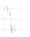
- step S101 the UE 10 transmits a Registration Request signal to the 5GC 20.
- step S102 the 5GC 20 confirms the contract details of the UE 10 by inquiring, for example, a contract DB (Database).
- a contract DB Database
- the 5GC 20 transmits a registration rejection signal (Registration Reject) to the UE 10 in step S103.
- 5GC notifies the terminal of Cause #27 indicating the reason for refusal of registration.
- the UE 10 Upon receiving the registration rejection signal, the UE 10 disables the N1 mode (5GC capability) in step S104.
- “disabling the N1 mode” may mean “turning off (the function of) the N1 mode”.
- “to enable the N1 mode” may mean “to turn on (the function of) the N1 mode.”
- step S105 the UE 10 starts an implementation-dependent timer to keep the N1 mode disabled for a certain period of time.
- step S106 the UE 10 transmits an Attach Request signal to the EPC 30.
- step S107 the EPC 30 transmits an Attach Accept signal to the UE 10.
- the UE 10 transitions from the 5GC 20 to the EPC 30 upon receiving the attach acceptance signal.
- Operation example 1 is an example of introducing a new feature to the EPC 30 side.
- operation example 1 as described with reference to FIG. 1, it is assumed that the UE 10 has started disabling the N1 mode (the timer is counting) triggered by the reception of Cause #27. .
- Operation Example 1 will be described below with reference to FIG.
- step S201 the EPC 30 confirms granting of the 5GC contract to the UE 10. This confirmation is performed, for example, by the EPC 30 periodically polling the contract DB, and by the contract DB notifying the EPC 30 of the 5GC contract grant when the 5GC contract is granted to the UE 10. you can
- step S202 an N1 mode connection permission signal indicating that the UE 10 is permitted to connect to the 5GC 20, which is a new feature, is sent to the UE 10. Send.
- the UE 10 Upon receiving the N1 mode connection acceptance signal, the UE 10 stops the timer in step S203.
- the UE 10 activates the N1 mode and tries to connect to the 5GC 20.
- the UE 10 sends the N1 mode connection acceptance signal stop the timer upon receipt of This allows the UE 10 to transition from the EPC 30 to the 5GC 20 more timely without frequently trying to connect to the 5GC 20 .
- Operation example 2 is an example in which operation example 1 is expanded. Therefore, in the operation example 2 as well, as described with reference to FIG. 1, the UE 10 starts disabling the N1 mode with the reception of Cause #27 (N1 mode not allowed) as a trigger (the timer is running is). Operation example 2 will be described below with reference to FIG.
- step S201 the EPC 30 confirms granting of the 5GC contract to the UE 10.
- the EPC 30 confirms that the UE 10 exists within a specific area based on the information reported from the UE 10 that indicates the location of the UE 10, the capabilities, the slice that the UE 10 is using, and the like.
- the specific area may mean an area of cells under the 5GC or a narrower area within this area.
- the EPC 30 After confirming that the UE 10 has been granted the 5GC contract and that the UE 10 exists within the specific area, the EPC 30 transmits an N1 mode connection acceptance signal to the UE 10 in step S202.
- the UE 10 Upon receiving the N1 mode connection acceptance signal, the UE 10 stops the timer in step S203.
- the UE 10 When the timer stops, the UE 10 activates the N1 mode and tries to connect to the 5GC 20.
- the EPC 30 confirms that the 5GC contract has been granted to the UE 10, that is, after the UE 10 is ready to connect to the 5GC 20, and the UE 10 is specified area, stop the timer in response to the reception of the N1 mode connection acceptance signal.
- the UE 10 does not unnecessarily search for cells under the 5GC, so that the UE 10 can transition from the EPC 30 to the 5GC 20 more timely without causing a large increase in power consumption.
- Operation example 3 is an example of introducing new features to the UE 10 and 5GC 20 sides instead of introducing new features to the EPC 30 side.
- a criterion is provided in advance for activating the N1 mode when the UE 10 cannot connect to the 5GC 20 and is located in the EPC 30 .
- Criteria are associated with existing elements of the EPC 30 .
- the criteria may be when the UE 10 receives a specific existing signal from the EPC 30, and the existing signal may be, for example, a Detach Request signal, but is not limited thereto. Note that the criteria may be read as criteria, conditions, and the like.
- the UE 10 transmits a registration request signal to the 5GC 20.
- the 5GC 20 confirms the contract details of the UE 10.
- the 5GC 20 sends a registration rejection signal to the UE 10 with Cause #27 (N1 mode not allowed) along with the criteria in step S103a. Thereby, the criteria are set in the UE 10 .
- the UE 10 Upon receiving the registration rejection signal, the UE 10 disables the N1 mode in step S104 and starts the timer in step S105.
- the UE 10 transmits an attach request signal to the EPC 30 in step S106.
- the EPC 30 transmits an attach acceptance signal to the UE 10 in step S107.
- the UE 10 transitions from the 5GC 20 to the EPC 30.
- step S201 the EPC 30 confirms granting of the 5GC contract to the UE 10.
- the EPC 30 Upon confirming that the 5GC contract has been granted to the UE 10, the EPC 30 transmits the existing signal to the UE 10 in step S401.
- the UE 10 Upon receiving the existing signal, the UE 10 confirms in step S402 that the existing signal meets the criteria. For example, if the criteria are that the UE 10 receives the detach request signal from the EPC 30 and the existing signal received by the UE 10 is the detach request signal, the UE 10 determines that the existing signal meets the criteria.
- the UE 10 stops the timer in step S203.
- the UE 10 When the timer stops, the UE 10 activates the N1 mode and tries to connect to the 5GC 20.
- the UE 10 stops the timer after it is confirmed that the UE 10 has been granted a 5GC contract, that is, after the UE 10 becomes ready to connect to the 5GC 20. This allows the UE 10 to transition from the EPC 30 to the 5GC 20 more timely without frequently trying to connect to the 5GC 20 .
- the criteria are not limited to the above examples.
- the criteria include a message received by the UE 10 from the EPC 30, a set value of an information element (IE: Information Element) in the message received by the UE 10 from the EPC 30, a location registration area in which the message received by the UE 10 from the EPC 30, and the like.
- IE Information Element
- Each may be a specific message, a specific value, a specific area, or a combination thereof.
- Terminal 10 includes the functionality described in the above example. However, the terminal 10 may include only some of the functions described in the above example.
- FIG. 6 is a diagram illustrating an example of a functional configuration of terminal 10 according to an embodiment of the present disclosure.
- the terminal 10 includes a transmitter 510 , a receiver 520 , a setter 530 and a controller 540 .
- the functional configuration shown in FIG. 6 is merely an example. As long as the operation according to the embodiment of the present disclosure can be executed, the functional division and the name of the functional unit may be anything.
- the transmission unit 510 generates a transmission signal from transmission data and wirelessly transmits the generated transmission signal.
- the transmission unit 510 transmits a registration request signal, an attach request signal, and the like.
- the receiving unit 520 wirelessly receives various signals and acquires a higher layer signal from the received physical layer signal.
- the receiving unit 520 receives a registration rejection signal, an attach acceptance signal, an N1 mode connection acceptance signal, a detachment request signal, and the like.
- the setting unit 530 stores various setting information received from the base station by the receiving unit 520 in a storage device (storage unit), and reads the setting information from the storage device as necessary.
- the setting unit 530 also stores preset information that is set in advance in the storage device. Note that the setting unit 530 may be included in the control unit 540 .
- the control unit 540 controls the terminal 10 as a whole.
- the control unit 540 performs control related to communication related to switching between 5GC and EPC, for example.
- a functional unit related to signal transmission in control unit 540 may be included in transmitting unit 510
- a functional unit related to signal reception in control unit 540 may be included in receiving unit 520 .
- each functional block may be implemented using one device that is physically or logically coupled, or directly or indirectly using two or more devices that are physically or logically separated (e.g. , wired, wireless, etc.) and may be implemented using these multiple devices.
- a functional block may be implemented by combining software in the one device or the plurality of devices.
- Functions include judging, determining, determining, calculating, calculating, processing, deriving, investigating, searching, checking, receiving, transmitting, outputting, accessing, resolving, selecting, choosing, establishing, comparing, assuming, expecting, assuming, Broadcasting, notifying, communicating, forwarding, configuring, reconfiguring, allocating, mapping, assigning, etc. can't
- a functional block (component) that performs transmission is called a transmitting unit or transmitter.
- the implementation method is not particularly limited.
- a terminal or the like in one embodiment of the present disclosure may function as a computer that performs processing of the wireless communication method of the present disclosure.
- FIG. 7 is a diagram illustrating an example of a hardware configuration of a terminal according to an embodiment of the present disclosure;
- the terminal 10 described above may be physically configured as a computer device including a processor 1001, a memory 1002, a storage 1003, a communication device 1004, an input device 1005, an output device 1006, a bus 1007, and the like.
- the term "apparatus” can be read as a circuit, device, unit, or the like.
- the hardware configuration of the terminal 10 may be configured to include one or more of each device shown in the figure, or may be configured without some of the devices.
- Each function of the terminal 10 is performed by causing the processor 1001 to perform calculations, controlling communication by the communication device 1004, controlling communication by the communication device 1004, and controlling the communication by the memory 1002 and the It is realized by controlling at least one of data reading and writing in the storage 1003 .
- the processor 1001 for example, operates an operating system and controls the entire computer.
- the processor 1001 may be configured by a central processing unit (CPU) including an interface with peripheral devices, a control device, an arithmetic device, registers, and the like.
- CPU central processing unit
- the control unit 540 and the like described above may be implemented by the processor 1001 .
- the processor 1001 reads programs (program codes), software modules, data, etc. from at least one of the storage 1003 and the communication device 1004 to the memory 1002, and executes various processes according to them.
- programs program codes
- software modules software modules
- data etc.
- the control unit 540 of the terminal 10 may be implemented by a control program stored in the memory 1002 and running on the processor 1001, and other functional blocks may be similarly implemented.
- FIG. Processor 1001 may be implemented by one or more chips.
- the program may be transmitted from a network via an electric communication line.
- the memory 1002 is a computer-readable recording medium, and is composed of at least one of, for example, ROM (Read Only Memory), EPROM (Erasable Programmable ROM), EEPROM (Electrically Erasable Programmable ROM), RAM (Random Access Memory), etc. may be
- ROM Read Only Memory
- EPROM Erasable Programmable ROM
- EEPROM Electrical Erasable Programmable ROM
- RAM Random Access Memory
- the memory 1002 may also be called a register, cache, main memory (main storage device), or the like.
- the memory 1002 can store executable programs (program code), software modules, etc. for implementing a wireless communication method according to an embodiment of the present disclosure.
- the storage 1003 is a computer-readable recording medium, for example, an optical disk such as a CD-ROM (Compact Disc ROM), a hard disk drive, a flexible disk, a magneto-optical disk (for example, a compact disk, a digital versatile disk, a Blu-ray disk), smart card, flash memory (eg, card, stick, key drive), floppy disk, magnetic strip, and/or the like.
- Storage 1003 may also be called an auxiliary storage device.
- the storage medium described above may be, for example, a database, server, or other suitable medium including at least one of memory 1002 and storage 1003 .
- the communication device 1004 is hardware (transmitting/receiving device) for communicating between computers via at least one of a wired network and a wireless network, and is also called a network device, a network controller, a network card, a communication module, or the like.
- the communication device 1004 includes a high-frequency switch, a duplexer, a filter, a frequency synthesizer, etc., in order to realize at least one of, for example, frequency division duplex (FDD) and time division duplex (TDD).
- FDD frequency division duplex
- TDD time division duplex
- the transmitting unit 710, the transmitting unit 810, the transmitting unit 910, the receiving unit 720, the receiving unit 820, the receiving unit 920, etc. described above may be realized by the communication device 1004.
- the input device 1005 is an input device (for example, keyboard, mouse, microphone, switch, button, sensor, etc.) that receives input from the outside.
- the output device 1006 is an output device (eg, display, speaker, LED lamp, etc.) that outputs to the outside. Note that the input device 1005 and the output device 1006 may be integrated (for example, a touch panel).
- Each device such as the processor 1001 and the memory 1002 is connected by a bus 1007 for communicating information.
- the bus 1007 may be configured using a single bus, or may be configured using different buses between devices.
- the terminal 10 includes hardware such as a microprocessor, a digital signal processor (DSP), an ASIC (Application Specific Integrated Circuit), a PLD (Programmable Logic Device), and an FPGA (Field Programmable Gate Array).
- DSP digital signal processor
- ASIC Application Specific Integrated Circuit
- PLD Physical Location Deposition
- FPGA Field Programmable Gate Array
- a part or all of each functional block may be implemented by the hardware.
- processor 1001 may be implemented using at least one of these pieces of hardware.
- notification of information includes physical layer signaling (e.g., DCI (Downlink Control Information), UCI (Uplink Control Information)), higher layer signaling (e.g., RRC (Radio Resource Control) signaling, MAC (Medium Access Control) signaling, It may be implemented by broadcast information (MIB (Master Information Block), SIB (System Information Block)), other signals, or a combination thereof.
- RRC signaling may also be called an RRC message, and may be, for example, an RRC connection setup message, an RRC connection reconfiguration message, or the like.
- Each aspect/embodiment described in the present disclosure includes LTE (Long Term Evolution), LTE-A (LTE-Advanced), SUPER 3G, IMT-Advanced, 4G (4th generation mobile communication system), 5G (5th generation mobile communication system), FRA (Future Radio Access), NR (New Radio), W-CDMA (registered trademark), GSM (registered trademark), CDMA2000, UMB (Ultra Mobile Broadband), IEEE 802.11 (Wi-Fi (registered trademark) )), IEEE 802.16 (WiMAX®), IEEE 802.20, UWB (Ultra-WideBand), Bluetooth®, and other suitable systems and extended It may be applied to at least one of the next generation systems. Also, a plurality of systems may be applied in combination (for example, a combination of at least one of LTE and LTE-A and 5G, etc.).
- Base station operation Certain operations that are described in this disclosure as being performed by a base station may also be performed by its upper node in some cases.
- various operations performed for communication with a terminal may be performed by the base station and other network nodes other than the base station (e.g. MME or S-GW, etc. (including but not limited to).
- MME or S-GW network nodes other than the base station
- the case where there is one network node other than the base station is exemplified above, it may be a combination of a plurality of other network nodes (for example, MME and S-GW).
- (input/output direction) Information and the like can be output from the upper layer (or lower layer) to the lower layer (or higher layer). It may be input and output via multiple network nodes.
- Input/output information and the like may be stored in a specific location (for example, memory), or may be managed using a management table. Input/output information and the like can be overwritten, updated, or appended. The output information and the like may be deleted. The entered information and the like may be transmitted to another device.
- the determination may be made by a value represented by one bit (0 or 1), by a true/false value (Boolean: true or false), or by numerical comparison (for example, a predetermined value).
- Software whether referred to as software, firmware, middleware, microcode, hardware description language or otherwise, includes instructions, instruction sets, code, code segments, program code, programs, subprograms, and software modules. , applications, software applications, software packages, routines, subroutines, objects, executables, threads of execution, procedures, functions, and the like.
- software, instructions, information, etc. may be transmitted and received via a transmission medium.
- the software uses at least one of wired technology (coaxial cable, fiber optic cable, twisted pair, digital subscriber line (DSL), etc.) and wireless technology (infrared, microwave, etc.) to website, Wired and/or wireless technologies are included within the definition of transmission medium when sent from a server or other remote source.
- wired technology coaxial cable, fiber optic cable, twisted pair, digital subscriber line (DSL), etc.
- wireless technology infrared, microwave, etc.
- Information, signal Information, signals, etc. described in this disclosure may be represented using any of a variety of different technologies.
- data, instructions, commands, information, signals, bits, symbols, chips, etc. may refer to voltages, currents, electromagnetic waves, magnetic fields or magnetic particles, light fields or photons, or any of these. may be represented by a combination of
- the channel and/or symbols may be signaling.
- a signal may also be a message.
- a component carrier may also be called a carrier frequency, a cell, a frequency carrier, or the like.
- system As used in this disclosure, the terms “system” and “network” are used interchangeably.
- radio resources may be indexed.
- Base station wireless base station
- base station radio base station
- radio base station fixed station
- NodeB nodeB
- eNodeB eNodeB
- gNodeB gNodeB
- a base station may also be referred to by terms such as macrocell, small cell, femtocell, picocell, and the like.
- a base station can accommodate one or more (eg, three) cells.
- the overall coverage area of the base station can be partitioned into multiple smaller areas, each smaller area being associated with a base station subsystem (e.g., an indoor small base station (RRH: Communication services can also be provided by Remote Radio Head)).
- RRH indoor small base station
- the terms "cell” or “sector” refer to part or all of the coverage area of at least one of the base stations and base station subsystems that serve communication within such coverage.
- terminal In this disclosure, terms such as “Mobile Station (MS),” “user terminal,” “User Equipment (UE),” “terminal,” etc. may be used interchangeably. .
- a mobile station is defined by those skilled in the art as a subscriber station, mobile unit, subscriber unit, wireless unit, remote unit, mobile device, wireless device, wireless communication device, remote device, mobile subscriber station, access terminal, mobile terminal, wireless It may also be called a terminal, remote terminal, handset, user agent, mobile client, client, or some other suitable term.
- At least one of a base station and a mobile station may be called a transmitter, a receiver, a communication device, and the like. At least one of the base station and the mobile station may be a device mounted on a mobile object, the mobile object itself, or the like.
- the mobile object may be a vehicle (e.g., car, airplane, etc.), an unmanned mobile object (e.g., drone, self-driving car, etc.), or a robot (manned or unmanned ).
- at least one of the base station and the mobile station includes devices that do not necessarily move during communication operations.
- at least one of the base station and the mobile station may be an IoT (Internet of Things) device such as a sensor.
- IoT Internet of Things
- the base station in the present disclosure may be read as a user terminal.
- communication between a base station and a user terminal is replaced with communication between multiple user terminals (for example, D2D (Device-to-Device), V2X (Vehicle-to-Everything), etc.)
- the terminal 10 may have the functions that the base station has.
- words such as "up” and “down” may be replaced with words corresponding to inter-terminal communication (for example, "side”).
- uplink channels, downlink channels, etc. may be read as side channels.
- a terminal in the present disclosure may be read as a base station.
- the base station may have the functions of the terminal 10 described above.
- determining may encompass a wide variety of actions.
- “Judgement”, “determining” are, for example, judging, calculating, computing, processing, deriving, investigating, looking up, searching, inquiring (eg, lookup in a table, database, or other data structure), ascertaining as “judged” or “determined”, and the like.
- "judgment” and “decision” are used for receiving (e.g., receiving information), transmitting (e.g., transmitting information), input, output, access (accessing) (for example, accessing data in memory) may include deeming that something has been "determined” or “decided”.
- judgment and “decision” are considered to be “judgment” and “decision” by resolving, selecting, choosing, establishing, comparing, etc. can contain.
- judgment and “decision” can include considering that some action is “judgment” and “decision”.
- judgment (decision) may be read as “assuming”, “expecting”, “considering”, or the like.
- connection means any direct or indirect connection or connection between two or more elements, It can include the presence of one or more intermediate elements between two elements being “connected” or “coupled.” Couplings or connections between elements may be physical, logical, or a combination thereof. For example, “connection” may be read as "access”.
- two elements are defined using at least one of one or more wires, cables, and printed electrical connections and, as some non-limiting and non-exhaustive examples, in the radio frequency domain. , electromagnetic energy having wavelengths in the microwave and optical (both visible and invisible) regions, and the like.
- the reference signal may be abbreviated as RS (Reference Signal), or may be referred to as Pilot according to the applicable standard.
- a radio frame may consist of one or more frames in the time domain. Each frame or frames in the time domain may be referred to as a subframe. A subframe may also consist of one or more slots in the time domain. A subframe may be a fixed time length (eg, 1 ms) independent of numerology.
- a numerology may be a communication parameter that applies to the transmission and/or reception of a signal or channel. Numerology, for example, subcarrier spacing (SCS), bandwidth, symbol length, cyclic prefix length, transmission time interval (TTI), number of symbols per TTI, radio frame configuration, transmission and reception specific filtering operations performed by the receiver in the frequency domain, specific windowing operations performed by the transceiver in the time domain, and/or the like.
- SCS subcarrier spacing
- TTI transmission time interval
- radio frame configuration for example, transmission and reception specific filtering operations performed by the receiver in the frequency domain, specific windowing operations performed by the transceiver in the time domain, and/or the like.
- a slot may consist of one or more symbols (OFDM (Orthogonal Frequency Division Multiplexing) symbol, SC-FDMA (Single Carrier Frequency Division Multiple Access) symbol, etc.) in the time domain.
- a slot may be a unit of time based on numerology.
- a slot may contain multiple mini-slots. Each minislot may consist of one or more symbols in the time domain. A minislot may also be referred to as a subslot. A minislot may consist of fewer symbols than a slot.
- PDSCH (or PUSCH) transmitted in time units larger than minislots may be referred to as PDSCH (or PUSCH) mapping type A.
- PDSCH (or PUSCH) transmitted using minislots may be referred to as PDSCH (or PUSCH) mapping type B.
- Radio frames, subframes, slots, minislots and symbols all represent time units when transmitting signals. Radio frames, subframes, slots, minislots and symbols may be referred to by other corresponding designations.
- one subframe may be called a Transmission Time Interval (TTI)
- TTI Transmission Time Interval
- TTI Transmission Time Interval
- TTI Transmission Time Interval
- one slot or one minislot may be called a TTI.
- TTI Transmission Time Interval
- at least one of the subframe and TTI may be a subframe (1 ms) in existing LTE, a period shorter than 1 ms (eg, 1-13 symbols), or a period longer than 1 ms may be Note that the unit representing the TTI may be called a slot, mini-slot, or the like instead of a subframe.
- TTI refers to, for example, the minimum scheduling time unit in wireless communication.
- a base station performs scheduling to allocate radio resources (frequency bandwidth, transmission power, etc. that can be used by each user terminal) to each user terminal on a TTI basis.
- radio resources frequency bandwidth, transmission power, etc. that can be used by each user terminal
- a TTI may be a transmission time unit such as a channel-encoded data packet (transport block), code block, or codeword, or may be a processing unit such as scheduling and link adaptation. Note that when a TTI is given, the time interval (for example, the number of symbols) in which transport blocks, code blocks, codewords, etc. are actually mapped may be shorter than the TTI.
- one or more TTIs may be the minimum scheduling time unit. Also, the number of slots (the number of mini-slots) constituting the minimum time unit of the scheduling may be controlled.
- a TTI having a time length of 1 ms may be called a normal TTI (TTI in LTE Rel. 8-12), normal TTI, long TTI, normal subframe, normal subframe, long subframe, slot, or the like.
- a TTI that is shorter than a normal TTI may be called a shortened TTI, a short TTI, a partial or fractional TTI, a shortened subframe, a short subframe, a minislot, a subslot, a slot, and the like.
- the long TTI (e.g., normal TTI, subframe, etc.) may be replaced with a TTI having a time length exceeding 1 ms
- the short TTI e.g., shortened TTI, etc.
- a TTI having the above TTI length may be read instead.
- a resource block is a resource allocation unit in the time domain and the frequency domain, and may include one or more consecutive subcarriers in the frequency domain.
- the number of subcarriers included in the RB may be the same regardless of the neumerology, eg twelve.
- the number of subcarriers included in an RB may be determined based on neumerology.
- the time domain of an RB may include one or more symbols and may be 1 slot, 1 minislot, 1 subframe, or 1 TTI long.
- One TTI, one subframe, etc. may each consist of one or more resource blocks.
- One or more RBs are physical resource blocks (PRBs), sub-carrier groups (SCGs), resource element groups (REGs), PRB pairs, RB pairs, etc. may be called.
- PRBs physical resource blocks
- SCGs sub-carrier groups
- REGs resource element groups
- PRB pairs RB pairs, etc. may be called.
- a resource block may be composed of one or more resource elements (RE: Resource Element).
- RE Resource Element
- 1 RE may be a radio resource region of 1 subcarrier and 1 symbol.
- a bandwidth part (which may also be called a bandwidth part) represents a subset of contiguous common resource blocks (RBs) for a certain numerology in a certain carrier. good.
- the common RB may be identified by an RB index based on the common reference point of the carrier.
- PRBs may be defined in a BWP and numbered within that BWP.
- the BWP may include a BWP for UL (UL BWP) and a BWP for DL (DL BWP).
- UL BWP UL BWP
- DL BWP DL BWP
- One or multiple BWPs may be configured for a UE within one carrier.
- At least one of the configured BWPs may be active, and the UE may not expect to transmit or receive a given signal/channel outside the active BWP.
- BWP bitmap
- radio frames, subframes, slots, minislots and symbols are only examples.
- the number of subframes contained in a radio frame the number of slots per subframe or radio frame, the number of minislots contained within a slot, the number of symbols and RBs contained in a slot or minislot, the number of Configurations such as the number of subcarriers, the number of symbols in a TTI, the symbol length, the cyclic prefix (CP) length, etc.
- CP cyclic prefix
- a and B are different may mean “A and B are different from each other.”
- the term may also mean that "A and B are different from C”.
- Terms such as “separate,” “coupled,” etc. may also be interpreted in the same manner as “different.”
- notification of predetermined information is not limited to being performed explicitly, but may be performed implicitly (for example, not notifying the predetermined information). good too.
- One aspect of the present disclosure is useful for wireless communication systems.
Landscapes
- Engineering & Computer Science (AREA)
- Computer Security & Cryptography (AREA)
- Computer Networks & Wireless Communication (AREA)
- Signal Processing (AREA)
- Mobile Radio Communication Systems (AREA)
Abstract
Selon un aspect, la présente invention concerne un terminal qui tente de se connecter à un premier réseau après l'arrêt d'un temporisateur et comprend : une unité de réception qui reçoit, à partir d'un second réseau, un signal d'autorisation de connexion indiquant une autorisation de connexion au premier réseau ; et une unité de commande qui, lors de la réception du signal d'autorisation de connexion, arrête le temporisateur en fonctionnement.
Priority Applications (2)
| Application Number | Priority Date | Filing Date | Title |
|---|---|---|---|
| JP2023541174A JPWO2023017589A1 (fr) | 2021-08-11 | 2021-08-11 | |
| PCT/JP2021/029668 WO2023017589A1 (fr) | 2021-08-11 | 2021-08-11 | Terminal et procédé de communication |
Applications Claiming Priority (1)
| Application Number | Priority Date | Filing Date | Title |
|---|---|---|---|
| PCT/JP2021/029668 WO2023017589A1 (fr) | 2021-08-11 | 2021-08-11 | Terminal et procédé de communication |
Publications (1)
| Publication Number | Publication Date |
|---|---|
| WO2023017589A1 true WO2023017589A1 (fr) | 2023-02-16 |
Family
ID=85200138
Family Applications (1)
| Application Number | Title | Priority Date | Filing Date |
|---|---|---|---|
| PCT/JP2021/029668 WO2023017589A1 (fr) | 2021-08-11 | 2021-08-11 | Terminal et procédé de communication |
Country Status (2)
| Country | Link |
|---|---|
| JP (1) | JPWO2023017589A1 (fr) |
| WO (1) | WO2023017589A1 (fr) |
Citations (1)
| Publication number | Priority date | Publication date | Assignee | Title |
|---|---|---|---|---|
| WO2020031734A1 (fr) * | 2018-08-10 | 2020-02-13 | シャープ株式会社 | Dispositif utilisateur, dispositif de commande et procédé de commande de communication |
-
2021
- 2021-08-11 WO PCT/JP2021/029668 patent/WO2023017589A1/fr active Application Filing
- 2021-08-11 JP JP2023541174A patent/JPWO2023017589A1/ja active Pending
Patent Citations (1)
| Publication number | Priority date | Publication date | Assignee | Title |
|---|---|---|---|---|
| WO2020031734A1 (fr) * | 2018-08-10 | 2020-02-13 | シャープ株式会社 | Dispositif utilisateur, dispositif de commande et procédé de commande de communication |
Non-Patent Citations (1)
| Title |
|---|
| NOKIA, NOKIA SHANGHAI BELL, VERIZON, MEDIATEK INC., ERICSSON: "Rejecting access to 5GCN with a timer", 3GPP DRAFT; C1-205178, 3RD GENERATION PARTNERSHIP PROJECT (3GPP), MOBILE COMPETENCE CENTRE ; 650, ROUTE DES LUCIOLES ; F-06921 SOPHIA-ANTIPOLIS CEDEX ; FRANCE, vol. CT WG1, no. Electronic meeting; 20200820 - 20200828, 13 August 2020 (2020-08-13), Mobile Competence Centre ; 650, route des Lucioles ; F-06921 Sophia-Antipolis Cedex ; France , XP051919666 * |
Also Published As
| Publication number | Publication date |
|---|---|
| JPWO2023017589A1 (fr) | 2023-02-16 |
Similar Documents
| Publication | Publication Date | Title |
|---|---|---|
| EP3681204B1 (fr) | Équipement utilisateur, noeud de réseau et système de communication | |
| JP7245266B2 (ja) | ネットワークノード、ネットワークシステム及び通知方法 | |
| JP7339956B2 (ja) | 端末、無線通信方法及び無線通信システム | |
| JP7163419B2 (ja) | 無線ノード、及び、無線通信制御方法 | |
| JP7122400B2 (ja) | 無線ノード、及び、無線通信制御方法 | |
| JP7285853B2 (ja) | 端末、基地局、通信システム及び通信方法 | |
| WO2022168767A1 (fr) | Station de base sans fil, système et procédé de communication sans fil | |
| JP2023016940A (ja) | 端末、無線通信システム及び無線通信方法 | |
| EP4243478A1 (fr) | Terminal et station de base sans fil | |
| US20240147330A1 (en) | Terminal | |
| WO2022085158A1 (fr) | Terminal et station de base sans fil | |
| JP7288514B2 (ja) | 端末、無線通信方法及び無線通信システム | |
| WO2023017589A1 (fr) | Terminal et procédé de communication | |
| JP7248709B2 (ja) | 端末、基地局、通信方法及び無線通信システム | |
| JP7250048B2 (ja) | 端末、基地局、通信方法及び無線通信システム | |
| CN114375587B (zh) | 终端 | |
| WO2022239244A1 (fr) | Station de base sans fil, terminal et procédé de communication sans fil | |
| JP7292071B2 (ja) | 基地局及び無線通信制御方法 | |
| WO2022201475A1 (fr) | Station de base, système et procédé de notification d'informations | |
| WO2022201476A1 (fr) | Station de base et système | |
| WO2022190334A1 (fr) | Terminal et procédé de communication | |
| JP7438232B2 (ja) | 端末 | |
| WO2022185501A1 (fr) | Terminal et procédé de communication | |
| WO2023022150A1 (fr) | Terminal, système de communication sans fil et procédé de communication sans fil | |
| WO2022234665A1 (fr) | Terminal, système de communication et procédé de commande |
Legal Events
| Date | Code | Title | Description |
|---|---|---|---|
| 121 | Ep: the epo has been informed by wipo that ep was designated in this application |
Ref document number: 21953484 Country of ref document: EP Kind code of ref document: A1 |
|
| WWE | Wipo information: entry into national phase |
Ref document number: 2023541174 Country of ref document: JP |
|
| NENP | Non-entry into the national phase |
Ref country code: DE |