WO2023012946A1 - 光ファイバ - Google Patents
光ファイバ Download PDFInfo
- Publication number
- WO2023012946A1 WO2023012946A1 PCT/JP2021/029010 JP2021029010W WO2023012946A1 WO 2023012946 A1 WO2023012946 A1 WO 2023012946A1 JP 2021029010 W JP2021029010 W JP 2021029010W WO 2023012946 A1 WO2023012946 A1 WO 2023012946A1
- Authority
- WO
- WIPO (PCT)
- Prior art keywords
- core
- optical fiber
- clad
- refractive index
- loss
- Prior art date
- Legal status (The legal status is an assumption and is not a legal conclusion. Google has not performed a legal analysis and makes no representation as to the accuracy of the status listed.)
- Ceased
Links
Images




Classifications
-
- G—PHYSICS
- G02—OPTICS
- G02B—OPTICAL ELEMENTS, SYSTEMS OR APPARATUS
- G02B6/00—Light guides; Structural details of arrangements comprising light guides and other optical elements, e.g. couplings
- G02B6/02—Optical fibres with cladding with or without a coating
- G02B6/02295—Microstructured optical fibre
- G02B6/02314—Plurality of longitudinal structures extending along optical fibre axis, e.g. holes
- G02B6/02342—Plurality of longitudinal structures extending along optical fibre axis, e.g. holes characterised by cladding features, i.e. light confining region
- G02B6/02366—Single ring of structures, e.g. "air clad"
-
- G—PHYSICS
- G02—OPTICS
- G02B—OPTICAL ELEMENTS, SYSTEMS OR APPARATUS
- G02B6/00—Light guides; Structural details of arrangements comprising light guides and other optical elements, e.g. couplings
- G02B6/02—Optical fibres with cladding with or without a coating
- G02B6/032—Optical fibres with cladding with or without a coating with non solid core or cladding
-
- G—PHYSICS
- G02—OPTICS
- G02B—OPTICAL ELEMENTS, SYSTEMS OR APPARATUS
- G02B6/00—Light guides; Structural details of arrangements comprising light guides and other optical elements, e.g. couplings
- G02B6/02—Optical fibres with cladding with or without a coating
- G02B6/036—Optical fibres with cladding with or without a coating core or cladding comprising multiple layers
Definitions
- the present disclosure relates to optical fibers with low loss characteristics.
- Optical fibers are used in many industrial fields, including information communication.
- Optical fiber loss is a factor that limits optical transmission quality, transmission distance, and efficiency, and various techniques have been proposed to reduce optical fiber loss.
- optical fibers for information communication use quartz glass as a base material.
- An optical fiber with a pure silica core achieves a loss of 0.142 dB/km by optimizing the structure, manufacturing process, and manufacturing conditions (see, for example, Non-Patent Document 1).
- Hollow-core optical fibers that employ a hollow-core structure have been proposed. Hollow-core optical fibers can reduce material-specific losses due to fused silica by confining light waves in the hollow core. Photonic bandgap optical fibers and anti-resonant optical fibers have been proposed as hollow-core optical fibers (see, for example, Non-Patent Document 2).
- the present disclosure removes the loss component generated at the core-clad interface and the electric field part that seeps into the clad region, while reducing the scattering loss generated at the interface with the clad region.
- An object of the present invention is to provide an optical fiber with a simple structure.
- the optical fiber of the present disclosure has an air layer between the core and the clad, and has a structure in which the core is supported by bridges.
- the present disclosure provides a core for propagating light; a clad arranged around the core; an air layer between the core and the clad; two or more bridges supporting the core in the air space;
- An optical fiber comprising
- the optical fiber of the present disclosure removes the loss component generated at the core-clad interface and the electric field part that seeps into the clad region, and reduces the scattering loss generated at the interface with the clad region. , can have a simple structure.
- optical fiber of the present disclosure is The clad has a lower refractive index than the core.
- the optical fiber of the present disclosure is When the number of propagation modes is (n+1), the refractive index of the clad is lower than the effective refractive index of the nth mode and higher than the effective refractive index of the (n+1)th mode.
- the optical fiber of the present disclosure is A thickness of the air layer is 1.6 ⁇ m or less.
- optical fiber of the present disclosure is The relative refractive index difference ⁇ of the core with respect to the clad is, with respect to the radius a of the core, It is characterized by
- an optical fiber with a simple structure is provided while eliminating loss components generated at the core-cladding interface and the electric field portion leaking into the cladding region and reducing scattering loss generated at the interface with the cladding region. be able to.
- FIG. 4 is a diagram for explaining the relationship between the relative refractive index difference between the core and the clad and the confinement loss; It is a figure explaining the relationship of the confinement loss and effective cross-sectional area with respect to a wavelength. It is a figure explaining the relationship of the bending loss in wavelength 1625nm with respect to bending radius.
- FIGS. 1A and 1B The structure of the optical fiber of the present disclosure is shown in FIGS. 1A and 1B.
- 1A and 1B are cross sections perpendicular to the longitudinal direction of the optical fiber.
- 10 is an optical fiber
- 11 is a core
- 12 is an air layer
- 13 is a clad
- 14 is a bridge.
- the optical fiber 10 of the present disclosure has an air layer 12 between a core 11 that propagates light and a clad 13 arranged around it, and has a structure in which the core 11 is supported by bridges 14 in the air layer 12. .
- This structure is uniform along the longitudinal axis of the optical fiber.
- the optical fiber of the present disclosure has a structure in which the core 11 is supported by the bridge 14, so the structure can be simpler than that of the hollow core optical fiber.
- the light wave propagates only inside the air layer 12 due to total reflection, and the electric field distribution of the propagation mode is also confined within the core 11. Therefore, the loss component generated at the core-clad interface and the electric field part leaking into the clad region can be removed to reduce the scattering loss that occurs at the interface with the cladding region. Therefore, the transmission loss is dominated by the loss peculiar to the material forming the core 11, and the loss can be reduced as compared with the conventional optical fiber.
- the cross section of the bridge is square in FIG. 1A, it may be circular as shown in FIG. 1B. It may also be oval, elliptical, square with rounded corners, concentric circles, or the like. Although the number of bridges 14 is four in FIG. 1A, two or more bridges are sufficient. It is sufficient if the air layer 12 exists between the core 11 and the clad 13 and the bridge 14 can fix the core 11 to the center of the clad 13 .
- quartz glass is generally used for the core 11, clad 13, and bridge 14.
- the core 11, the clad 13, and the bridge 14 may be doped with trace amounts of impurities such as GeO2, F, Cl, P, and Al2O3 in order to control the refractive index and material properties. and/or amount may be different.
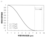
- FIG. 2 An example of the electric field distribution in the optical fiber according to FIG. 1A of the present disclosure is shown in FIG.
- the horizontal axis represents the position in the radial direction
- the vertical axis represents the normalized electric field intensity.
- the core radius a 7.5 ⁇ m
- the air layer thickness d 2.0 ⁇ m
- the bridge width w 1.0 ⁇ m.
- FIG. 2 shows the electric field strength distribution in the axis along which the bridge exists in the radial direction from the center of the optical fiber.
- the electric field distribution is sufficiently confined within the core radius of 7.5 ⁇ m or less, and the electric field spreading to the bridge region is 0.1% or less, so it can be confirmed that the loss characteristic is dominated by the core material.
- the loss component generated at the core-clad interface and the electric field part leaking into the clad region is removed, and the scattering loss generated at the interface with the clad region is reduced. can be done.
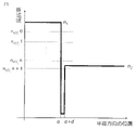
- FIG. 3 shows a schematic diagram showing the relationship between the refractive index profile of the optical fiber according to the present disclosure and the waveguide mode.
- the horizontal axis represents the position in the radial direction
- the vertical axis represents the refractive index.
- the refractive index from the center to the core radius a is n1
- the refractive index of the air layer is 1
- the refractive index from the clad position a+d is n2.
- the latter number of the effective refractive index n eff is the order of the propagation mode.
- the 0th order is the fundamental mode.
- the refractive index of the cladding 13 is set lower than the effective refractive index of the n-th order propagation mode and higher than the effective refractive index of the n+1-th order propagation mode, Higher-order modes after the n+1 order can be leaked, and the propagation mode can be n-order or lower.
- the number of propagation modes can be controlled by defining either or both of the refractive index of the core 11 and the refractive index of the clad 13.
- the relationship between the air layer thickness d and the confinement loss for the fundamental mode is shown in FIG. 4A
- the relationship between the air layer thickness d and the confinement loss for the first higher mode is shown in FIG. 4B.
- the wavelength used was 1550 nm
- the bridge width w was 1.0 ⁇ m
- the air layer thickness d is 1.55 ⁇ m or less, which is the wavelength of the propagating light, the confinement loss becomes several hundred dB/km or more, resulting in a leaky mode.
- the thickness d of the air layer is desirably 1.6 ⁇ m or less.
- the desired high-order mode can be leaked when the air layer thickness d is about the wavelength used or less because the confinement effect of the air layer 12 is very strong.
- FIG. 5 shows the relationship between the core radius a, the effective refractive index ⁇ eff of the propagation mode, and the effective cross-sectional area of the optical fiber of the present disclosure.
- the wavelength was set to 1550 nm.
- the vertical axis ⁇ eff on the left side is the relative refractive index difference with respect to the effective refractive index of the fundamental mode and the first higher order mode of the core refractive index n1, defined in
- the effective cross-sectional area of the core can be uniquely determined only by the core radius.
- the core radius a should be 7 ⁇ m or more.
- FIG. 6 shows the relationship between the core-cladding relative refractive index difference ⁇ and the confinement loss in the optical fiber of the present disclosure.
- the loss decreases sharply when the relative refractive index difference ⁇ is about ⁇ 0.15% or less, whereas in the first higher-order mode, the loss is sufficiently large at about ⁇ 0.4% or less. Since it becomes a confinement loss, it is possible to operate in a single mode in the range of -0.15% to -0.4% for ⁇ , thereby reducing the fundamental mode loss. This range is relatively consistent with the formula (3).
- FIG. 7A The relationship between confinement loss and effective area versus wavelength for the optical fiber of the present disclosure is shown in FIG. 7A.
- a single-mode operation is employed within the wavelength range of 1530 to 1625 nm, and the structure is such that loss in the fundamental mode can be reduced. From FIG. 7A, it can be confirmed that while the confinement loss in the fundamental mode is sufficiently small as 10 ⁇ 7 dB/km or less, the first higher-order mode leaks with a very large loss of 1000 dB/km or more.
- the effective cross-sectional area is about 88 ⁇ m 2 , and it can be seen that the wavelength dependence is very small.
- the optical fiber of the present disclosure can obtain the effect of expanding the effective area especially on the short wavelength side, and can obtain low nonlinearity. I understand.
- FIG. 7B shows the relationship between the bending loss at a wavelength of 1625 nm and the bending radius of the optical fiber of the present disclosure.
- the bending loss decreases as the bending radius increases, and it can be confirmed that a bending loss of 0.1 dB/100 turn or less is obtained at a bending radius of 30 mm or more, which is equal to or less than that of a general-purpose optical fiber.
- the optical fiber of the present disclosure eliminates the loss component generated at the core-clad interface and the electric field part that seeps into the clad region, reduces the scattering loss generated at the interface with the clad region, and has a simple structure.
- This disclosure can be applied to the communications industry.
- optical fiber 11 core 12: air layer 13: clad 14: bridge
Landscapes
- Physics & Mathematics (AREA)
- General Physics & Mathematics (AREA)
- Optics & Photonics (AREA)
- Optical Fibers, Optical Fiber Cores, And Optical Fiber Bundles (AREA)
- Lasers (AREA)
Priority Applications (3)
| Application Number | Priority Date | Filing Date | Title |
|---|---|---|---|
| JP2023539463A JP7626231B2 (ja) | 2021-08-04 | 2021-08-04 | 光ファイバ |
| PCT/JP2021/029010 WO2023012946A1 (ja) | 2021-08-04 | 2021-08-04 | 光ファイバ |
| US18/294,124 US20250093575A1 (en) | 2021-08-04 | 2021-08-04 | Optical fiber |
Applications Claiming Priority (1)
| Application Number | Priority Date | Filing Date | Title |
|---|---|---|---|
| PCT/JP2021/029010 WO2023012946A1 (ja) | 2021-08-04 | 2021-08-04 | 光ファイバ |
Publications (1)
| Publication Number | Publication Date |
|---|---|
| WO2023012946A1 true WO2023012946A1 (ja) | 2023-02-09 |
Family
ID=85154462
Family Applications (1)
| Application Number | Title | Priority Date | Filing Date |
|---|---|---|---|
| PCT/JP2021/029010 Ceased WO2023012946A1 (ja) | 2021-08-04 | 2021-08-04 | 光ファイバ |
Country Status (3)
| Country | Link |
|---|---|
| US (1) | US20250093575A1 (https=) |
| JP (1) | JP7626231B2 (https=) |
| WO (1) | WO2023012946A1 (https=) |
Citations (7)
| Publication number | Priority date | Publication date | Assignee | Title |
|---|---|---|---|---|
| JPS5034550A (https=) * | 1973-07-28 | 1975-04-02 | ||
| US7006751B2 (en) * | 2003-05-27 | 2006-02-28 | Draka Comteo | Optical fiber for amplification or for laser emission |
| US20070104436A1 (en) * | 2005-10-20 | 2007-05-10 | Ming-Jun Li | High numerical aperture optical fiber |
| JP2008242459A (ja) * | 2007-03-27 | 2008-10-09 | Imra America Inc | 超高開口数光ファイバ |
| CN102359955A (zh) * | 2011-07-29 | 2012-02-22 | 北京航空航天大学 | 一种基于开放式微结构光纤的气体拉曼检测装置 |
| JP2018163317A (ja) * | 2017-03-27 | 2018-10-18 | 古河電気工業株式会社 | 光ファイバ集合体及びマルチコア光ファイバ |
| JP2020095128A (ja) * | 2018-12-12 | 2020-06-18 | 古河電気工業株式会社 | 光ファイバおよび光システム |
-
2021
- 2021-08-04 JP JP2023539463A patent/JP7626231B2/ja active Active
- 2021-08-04 US US18/294,124 patent/US20250093575A1/en active Pending
- 2021-08-04 WO PCT/JP2021/029010 patent/WO2023012946A1/ja not_active Ceased
Patent Citations (7)
| Publication number | Priority date | Publication date | Assignee | Title |
|---|---|---|---|---|
| JPS5034550A (https=) * | 1973-07-28 | 1975-04-02 | ||
| US7006751B2 (en) * | 2003-05-27 | 2006-02-28 | Draka Comteo | Optical fiber for amplification or for laser emission |
| US20070104436A1 (en) * | 2005-10-20 | 2007-05-10 | Ming-Jun Li | High numerical aperture optical fiber |
| JP2008242459A (ja) * | 2007-03-27 | 2008-10-09 | Imra America Inc | 超高開口数光ファイバ |
| CN102359955A (zh) * | 2011-07-29 | 2012-02-22 | 北京航空航天大学 | 一种基于开放式微结构光纤的气体拉曼检测装置 |
| JP2018163317A (ja) * | 2017-03-27 | 2018-10-18 | 古河電気工業株式会社 | 光ファイバ集合体及びマルチコア光ファイバ |
| JP2020095128A (ja) * | 2018-12-12 | 2020-06-18 | 古河電気工業株式会社 | 光ファイバおよび光システム |
Non-Patent Citations (1)
| Title |
|---|
| DUFOUR ALEXIS; BSAWMAII LAURE; JAMON DAMIEN; MARIN EMMANUEL; NEVEU SOPHIE; REYNAUD STEPHANIE; GIRARD SYLVAIN; ROYER FRANCOIS: "All-Fiber Magneto-Optical Effect Using Nanoparticles Doped Sol-Gel Thin Film Deposited Within Microstructured Fibers", JOURNAL OF LIGHTWAVE TECHNOLOGY, IEEE, USA, vol. 39, no. 17, 27 May 2021 (2021-05-27), USA, pages 5604 - 5610, XP011877363, ISSN: 0733-8724, DOI: 10.1109/JLT.2021.3084359 * |
Also Published As
| Publication number | Publication date |
|---|---|
| US20250093575A1 (en) | 2025-03-20 |
| JP7626231B2 (ja) | 2025-02-04 |
| JPWO2023012946A1 (https=) | 2023-02-09 |
Similar Documents
| Publication | Publication Date | Title |
|---|---|---|
| JP5469064B2 (ja) | 大モード面積光ファイバ | |
| US9645309B2 (en) | Large core holey fibers | |
| JP4904241B2 (ja) | ホーリーファイバ | |
| JP5643855B2 (ja) | 高sbs閾値の光ファイバ | |
| US7668428B2 (en) | Optical fiber and optical device | |
| JP3786010B2 (ja) | 光ファイバ | |
| US20110305251A1 (en) | Multi-cladding optical fiber, optical fiber module, fiber laser, and fiber amplifier | |
| WO2012043603A1 (ja) | ソリッドフォトニックバンドギャップファイバおよびソリッドフォトニックバンドギャップファイバを用いたファイバモジュールおよびファイバアンプ、ファイバレーザ | |
| US7978947B2 (en) | Photonic bandgap fiber | |
| JP5215699B2 (ja) | フォトニック結晶ファイバ | |
| Zhu et al. | Nested low-loss hollow core fiber | |
| JP7640382B2 (ja) | 光ファイバ接続構造 | |
| Zhou et al. | A negative-curvature hollow-core fiber structure with double trigonal-symmetrical anti-resonant elements | |
| JP4137515B2 (ja) | 分散シフト光ファイバ | |
| CN112968347B (zh) | 抑制受激拉曼散射的方法、高功率光纤激光器及全固态微结构光纤 | |
| JPWO2016167080A1 (ja) | 光ファイバ設計方法 | |
| JP7626231B2 (ja) | 光ファイバ | |
| JP3640943B2 (ja) | フォトニッククリスタルファイバ | |
| KR20050109450A (ko) | 브래그 격자 광섬유 | |
| JP7616393B2 (ja) | フォトニック結晶ファイバ | |
| JP2005140857A (ja) | 分散フラットファイバ | |
| CN214278469U (zh) | 全固态微结构光纤 | |
| Kothari et al. | Optimizing differential mode delay and crosstalk in nested anti-resonant node-less hollow-core fibers for mode-division multiplexing | |
| Zheng et al. | Design and performance analysis of a novel low confinement loss multimode hollow-core anti-resonant fiber | |
| JP2011170061A (ja) | 光ファイバおよび光ファイバの製造方法 |
Legal Events
| Date | Code | Title | Description |
|---|---|---|---|
| 121 | Ep: the epo has been informed by wipo that ep was designated in this application |
Ref document number: 21952772 Country of ref document: EP Kind code of ref document: A1 |
|
| WWE | Wipo information: entry into national phase |
Ref document number: 2023539463 Country of ref document: JP |
|
| WWE | Wipo information: entry into national phase |
Ref document number: 18294124 Country of ref document: US |
|
| NENP | Non-entry into the national phase |
Ref country code: DE |
|
| 122 | Ep: pct application non-entry in european phase |
Ref document number: 21952772 Country of ref document: EP Kind code of ref document: A1 |
|
| WWP | Wipo information: published in national office |
Ref document number: 18294124 Country of ref document: US |