WO2023012946A1 - Optical fiber - Google Patents
Optical fiber Download PDFInfo
- Publication number
- WO2023012946A1 WO2023012946A1 PCT/JP2021/029010 JP2021029010W WO2023012946A1 WO 2023012946 A1 WO2023012946 A1 WO 2023012946A1 JP 2021029010 W JP2021029010 W JP 2021029010W WO 2023012946 A1 WO2023012946 A1 WO 2023012946A1
- Authority
- WO
- WIPO (PCT)
- Prior art keywords
- core
- optical fiber
- clad
- refractive index
- loss
- Prior art date
Links
- 239000013307 optical fiber Substances 0.000 title claims abstract description 53
- 238000005253 cladding Methods 0.000 claims description 8
- 230000001902 propagating effect Effects 0.000 claims description 6
- 230000005684 electric field Effects 0.000 abstract description 16
- 239000011162 core material Substances 0.000 description 46
- 238000005452 bending Methods 0.000 description 8
- 238000009826 distribution Methods 0.000 description 7
- 239000000463 material Substances 0.000 description 5
- VYPSYNLAJGMNEJ-UHFFFAOYSA-N Silicium dioxide Chemical compound O=[Si]=O VYPSYNLAJGMNEJ-UHFFFAOYSA-N 0.000 description 4
- 230000005540 biological transmission Effects 0.000 description 3
- 238000004519 manufacturing process Methods 0.000 description 3
- 230000007423 decrease Effects 0.000 description 2
- 238000010586 diagram Methods 0.000 description 2
- 230000000694 effects Effects 0.000 description 2
- YBMRDBCBODYGJE-UHFFFAOYSA-N germanium dioxide Chemical compound O=[Ge]=O YBMRDBCBODYGJE-UHFFFAOYSA-N 0.000 description 2
- PNEYBMLMFCGWSK-UHFFFAOYSA-N aluminium oxide Inorganic materials [O-2].[O-2].[O-2].[Al+3].[Al+3] PNEYBMLMFCGWSK-UHFFFAOYSA-N 0.000 description 1
- 229910052801 chlorine Inorganic materials 0.000 description 1
- 239000000470 constituent Substances 0.000 description 1
- 229910052593 corundum Inorganic materials 0.000 description 1
- 239000000835 fiber Substances 0.000 description 1
- 229910052731 fluorine Inorganic materials 0.000 description 1
- 239000005350 fused silica glass Substances 0.000 description 1
- 239000012535 impurity Substances 0.000 description 1
- 238000000034 method Methods 0.000 description 1
- 230000003287 optical effect Effects 0.000 description 1
- 229910052698 phosphorus Inorganic materials 0.000 description 1
- 235000012239 silicon dioxide Nutrition 0.000 description 1
- 238000003892 spreading Methods 0.000 description 1
- 229910001845 yogo sapphire Inorganic materials 0.000 description 1
Images


Classifications
-
- G—PHYSICS
- G02—OPTICS
- G02B—OPTICAL ELEMENTS, SYSTEMS OR APPARATUS
- G02B6/00—Light guides; Structural details of arrangements comprising light guides and other optical elements, e.g. couplings
- G02B6/02—Optical fibres with cladding with or without a coating
- G02B6/032—Optical fibres with cladding with or without a coating with non solid core or cladding
-
- G—PHYSICS
- G02—OPTICS
- G02B—OPTICAL ELEMENTS, SYSTEMS OR APPARATUS
- G02B6/00—Light guides; Structural details of arrangements comprising light guides and other optical elements, e.g. couplings
- G02B6/02—Optical fibres with cladding with or without a coating
- G02B6/036—Optical fibres with cladding with or without a coating core or cladding comprising multiple layers
Definitions
- the present disclosure relates to optical fibers with low loss characteristics.
- Optical fibers are used in many industrial fields, including information communication.
- Optical fiber loss is a factor that limits optical transmission quality, transmission distance, and efficiency, and various techniques have been proposed to reduce optical fiber loss.
- optical fibers for information communication use quartz glass as a base material.
- An optical fiber with a pure silica core achieves a loss of 0.142 dB/km by optimizing the structure, manufacturing process, and manufacturing conditions (see, for example, Non-Patent Document 1).
- Hollow-core optical fibers that employ a hollow-core structure have been proposed. Hollow-core optical fibers can reduce material-specific losses due to fused silica by confining light waves in the hollow core. Photonic bandgap optical fibers and anti-resonant optical fibers have been proposed as hollow-core optical fibers (see, for example, Non-Patent Document 2).
- the present disclosure removes the loss component generated at the core-clad interface and the electric field part that seeps into the clad region, while reducing the scattering loss generated at the interface with the clad region.
- An object of the present invention is to provide an optical fiber with a simple structure.
- the optical fiber of the present disclosure has an air layer between the core and the clad, and has a structure in which the core is supported by bridges.
- the present disclosure provides a core for propagating light; a clad arranged around the core; an air layer between the core and the clad; two or more bridges supporting the core in the air space;
- An optical fiber comprising
- the optical fiber of the present disclosure removes the loss component generated at the core-clad interface and the electric field part that seeps into the clad region, and reduces the scattering loss generated at the interface with the clad region. , can have a simple structure.
- optical fiber of the present disclosure is The clad has a lower refractive index than the core.
- the optical fiber of the present disclosure is When the number of propagation modes is (n+1), the refractive index of the clad is lower than the effective refractive index of the nth mode and higher than the effective refractive index of the (n+1)th mode.
- the optical fiber of the present disclosure is A thickness of the air layer is 1.6 ⁇ m or less.
- optical fiber of the present disclosure is The relative refractive index difference ⁇ of the core with respect to the clad is, with respect to the radius a of the core, It is characterized by
- an optical fiber with a simple structure is provided while eliminating loss components generated at the core-cladding interface and the electric field portion leaking into the cladding region and reducing scattering loss generated at the interface with the cladding region. be able to.
- FIG. 4 is a diagram for explaining the relationship between the relative refractive index difference between the core and the clad and the confinement loss; It is a figure explaining the relationship of the confinement loss and effective cross-sectional area with respect to a wavelength. It is a figure explaining the relationship of the bending loss in wavelength 1625nm with respect to bending radius.
- FIGS. 1A and 1B The structure of the optical fiber of the present disclosure is shown in FIGS. 1A and 1B.
- 1A and 1B are cross sections perpendicular to the longitudinal direction of the optical fiber.
- 10 is an optical fiber
- 11 is a core
- 12 is an air layer
- 13 is a clad
- 14 is a bridge.
- the optical fiber 10 of the present disclosure has an air layer 12 between a core 11 that propagates light and a clad 13 arranged around it, and has a structure in which the core 11 is supported by bridges 14 in the air layer 12. .
- This structure is uniform along the longitudinal axis of the optical fiber.
- the optical fiber of the present disclosure has a structure in which the core 11 is supported by the bridge 14, so the structure can be simpler than that of the hollow core optical fiber.
- the light wave propagates only inside the air layer 12 due to total reflection, and the electric field distribution of the propagation mode is also confined within the core 11. Therefore, the loss component generated at the core-clad interface and the electric field part leaking into the clad region can be removed to reduce the scattering loss that occurs at the interface with the cladding region. Therefore, the transmission loss is dominated by the loss peculiar to the material forming the core 11, and the loss can be reduced as compared with the conventional optical fiber.
- the cross section of the bridge is square in FIG. 1A, it may be circular as shown in FIG. 1B. It may also be oval, elliptical, square with rounded corners, concentric circles, or the like. Although the number of bridges 14 is four in FIG. 1A, two or more bridges are sufficient. It is sufficient if the air layer 12 exists between the core 11 and the clad 13 and the bridge 14 can fix the core 11 to the center of the clad 13 .
- quartz glass is generally used for the core 11, clad 13, and bridge 14.
- the core 11, the clad 13, and the bridge 14 may be doped with trace amounts of impurities such as GeO2, F, Cl, P, and Al2O3 in order to control the refractive index and material properties. and/or amount may be different.
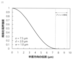
- FIG. 2 An example of the electric field distribution in the optical fiber according to FIG. 1A of the present disclosure is shown in FIG.
- the horizontal axis represents the position in the radial direction
- the vertical axis represents the normalized electric field intensity.
- the core radius a 7.5 ⁇ m
- the air layer thickness d 2.0 ⁇ m
- the bridge width w 1.0 ⁇ m.
- FIG. 2 shows the electric field strength distribution in the axis along which the bridge exists in the radial direction from the center of the optical fiber.
- the electric field distribution is sufficiently confined within the core radius of 7.5 ⁇ m or less, and the electric field spreading to the bridge region is 0.1% or less, so it can be confirmed that the loss characteristic is dominated by the core material.
- the loss component generated at the core-clad interface and the electric field part leaking into the clad region is removed, and the scattering loss generated at the interface with the clad region is reduced. can be done.
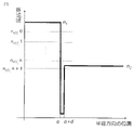
- FIG. 3 shows a schematic diagram showing the relationship between the refractive index profile of the optical fiber according to the present disclosure and the waveguide mode.
- the horizontal axis represents the position in the radial direction
- the vertical axis represents the refractive index.
- the refractive index from the center to the core radius a is n1
- the refractive index of the air layer is 1
- the refractive index from the clad position a+d is n2.
- the latter number of the effective refractive index n eff is the order of the propagation mode.
- the 0th order is the fundamental mode.
- the refractive index of the cladding 13 is set lower than the effective refractive index of the n-th order propagation mode and higher than the effective refractive index of the n+1-th order propagation mode, Higher-order modes after the n+1 order can be leaked, and the propagation mode can be n-order or lower.
- the number of propagation modes can be controlled by defining either or both of the refractive index of the core 11 and the refractive index of the clad 13.
- the relationship between the air layer thickness d and the confinement loss for the fundamental mode is shown in FIG. 4A
- the relationship between the air layer thickness d and the confinement loss for the first higher mode is shown in FIG. 4B.
- the wavelength used was 1550 nm
- the bridge width w was 1.0 ⁇ m
- the air layer thickness d is 1.55 ⁇ m or less, which is the wavelength of the propagating light, the confinement loss becomes several hundred dB/km or more, resulting in a leaky mode.
- the thickness d of the air layer is desirably 1.6 ⁇ m or less.
- the desired high-order mode can be leaked when the air layer thickness d is about the wavelength used or less because the confinement effect of the air layer 12 is very strong.
- FIG. 5 shows the relationship between the core radius a, the effective refractive index ⁇ eff of the propagation mode, and the effective cross-sectional area of the optical fiber of the present disclosure.
- the wavelength was set to 1550 nm.
- the vertical axis ⁇ eff on the left side is the relative refractive index difference with respect to the effective refractive index of the fundamental mode and the first higher order mode of the core refractive index n1, defined in
- the effective cross-sectional area of the core can be uniquely determined only by the core radius.
- the core radius a should be 7 ⁇ m or more.
- FIG. 6 shows the relationship between the core-cladding relative refractive index difference ⁇ and the confinement loss in the optical fiber of the present disclosure.
- the loss decreases sharply when the relative refractive index difference ⁇ is about ⁇ 0.15% or less, whereas in the first higher-order mode, the loss is sufficiently large at about ⁇ 0.4% or less. Since it becomes a confinement loss, it is possible to operate in a single mode in the range of -0.15% to -0.4% for ⁇ , thereby reducing the fundamental mode loss. This range is relatively consistent with the formula (3).
- FIG. 7A The relationship between confinement loss and effective area versus wavelength for the optical fiber of the present disclosure is shown in FIG. 7A.
- a single-mode operation is employed within the wavelength range of 1530 to 1625 nm, and the structure is such that loss in the fundamental mode can be reduced. From FIG. 7A, it can be confirmed that while the confinement loss in the fundamental mode is sufficiently small as 10 ⁇ 7 dB/km or less, the first higher-order mode leaks with a very large loss of 1000 dB/km or more.
- the effective cross-sectional area is about 88 ⁇ m 2 , and it can be seen that the wavelength dependence is very small.
- the optical fiber of the present disclosure can obtain the effect of expanding the effective area especially on the short wavelength side, and can obtain low nonlinearity. I understand.
- FIG. 7B shows the relationship between the bending loss at a wavelength of 1625 nm and the bending radius of the optical fiber of the present disclosure.
- the bending loss decreases as the bending radius increases, and it can be confirmed that a bending loss of 0.1 dB/100 turn or less is obtained at a bending radius of 30 mm or more, which is equal to or less than that of a general-purpose optical fiber.
- the optical fiber of the present disclosure eliminates the loss component generated at the core-clad interface and the electric field part that seeps into the clad region, reduces the scattering loss generated at the interface with the clad region, and has a simple structure.
- This disclosure can be applied to the communications industry.
- optical fiber 11 core 12: air layer 13: clad 14: bridge
Abstract
The purpose of the present disclosure is to provide an optical fiber having a simple structure while removing a loss component generated at an electric field part leaked to a core-clad interface or a clad region and reducing a scattering loss generated at the interface with the clad region. The present disclosure is an optical fiber (10) comprising: a core (11) that propagates light; a clad (13) that is disposed around the core (11); an air layer (12) that is between the core (11) and the clad (13); and at least two bridges (14) that support the core (11) in the air layer (12).
Description
本開示は、低損失特性の光ファイバに関する。
The present disclosure relates to optical fibers with low loss characteristics.
光ファイバは情報通信を始め、多くの産業分野で使用されている。光ファイバの損失は、光の伝送品質や伝送距離・効率を制限する要因となっており、光ファイバの損失を低減する様々な手法が提案されている。現在、情報通信用の光ファイバは石英ガラスを基軸材としている。純石英コアの光ファイバでは、構造や製造工程・製造条件の最適化により、0.142dB/kmの損失が達成されている(例えば、非特許文献1参照。)。
Optical fibers are used in many industrial fields, including information communication. Optical fiber loss is a factor that limits optical transmission quality, transmission distance, and efficiency, and various techniques have been proposed to reduce optical fiber loss. At present, optical fibers for information communication use quartz glass as a base material. An optical fiber with a pure silica core achieves a loss of 0.142 dB/km by optimizing the structure, manufacturing process, and manufacturing conditions (see, for example, Non-Patent Document 1).
一方、中空コア構造を採用する中空コア光ファイバが提案されている。中空コア光ファイバは、中空コアに光波を閉じ込めることによって、石英ガラスを起因とする材料固有の損失を低減することができる。中空コア光ファイバとして、フォトニックバンドギャップ光ファイバやアンチレゾナント光ファイバが提案されている(例えば、非特許文献2参照。)。
On the other hand, hollow-core optical fibers that employ a hollow-core structure have been proposed. Hollow-core optical fibers can reduce material-specific losses due to fused silica by confining light waves in the hollow core. Photonic bandgap optical fibers and anti-resonant optical fibers have been proposed as hollow-core optical fibers (see, for example, Non-Patent Document 2).
しかし、石英ガラスを基軸材とした光ファイバでは、コア-クラッド界面やクラッド領域に染み出した電界部分で生じる損失成分を完全に取り除くことはできず、石英ガラスが持つ材料由来の損失限界まで低減することが困難であった。
However, in an optical fiber using quartz glass as a base material, it is not possible to completely remove the loss component generated at the core-cladding interface and the electric field part that seeps into the clad region, and the loss is reduced to the limit of the material derived from quartz glass. was difficult to do.
中空コア光ファイバでは、クラッド領域との界面で生じる散乱損失の低減が困難である。また、構造が複雑であるため、製造には精密な制御が必要といった課題があった。
In hollow-core optical fibers, it is difficult to reduce the scattering loss that occurs at the interface with the cladding region. In addition, since the structure is complicated, there is a problem that precise control is required for manufacturing.
そこで、前述の課題を解決するために、本開示は、コア-クラッド界面やクラッド領域に染み出した電界部分で生じる損失成分を除去し、クラッド領域との界面で生じる散乱損失を低減しつつ、簡易な構造の光ファイバの提供を目的とする。
Therefore, in order to solve the above-mentioned problems, the present disclosure removes the loss component generated at the core-clad interface and the electric field part that seeps into the clad region, while reducing the scattering loss generated at the interface with the clad region. An object of the present invention is to provide an optical fiber with a simple structure.
前記課題を解決するために、本開示の光ファイバは、コアとクラッドとの間に空気層を備え、コアをブリッジで支持する構造とした。
In order to solve the above problems, the optical fiber of the present disclosure has an air layer between the core and the clad, and has a structure in which the core is supported by bridges.
具体的には、本開示は
光を伝搬させるコアと、
前記コアの周囲に配置されたクラッドと、
前記コアと前記クラッドとの間の空気層と、
前記空気層の中に、前記コアを支持する2つ以上のブリッジと、
を備える光ファイバ
である。 Specifically, the present disclosure provides a core for propagating light;
a clad arranged around the core;
an air layer between the core and the clad;
two or more bridges supporting the core in the air space;
An optical fiber comprising
このような構造とすることにより、本開示の光ファイバは、コア-クラッド界面やクラッド領域に染み出した電界部分で生じる損失成分を除去し、クラッド領域との界面で生じる散乱損失を低減しつつ、簡易な構造とすることができる。
With such a structure, the optical fiber of the present disclosure removes the loss component generated at the core-clad interface and the electric field part that seeps into the clad region, and reduces the scattering loss generated at the interface with the clad region. , can have a simple structure.
また、本開示の光ファイバは、
前記クラッドの屈折率が前記コアの屈折率に比べて低い
ことを特徴とする。 In addition, the optical fiber of the present disclosure is
The clad has a lower refractive index than the core.
前記クラッドの屈折率が前記コアの屈折率に比べて低い
ことを特徴とする。 In addition, the optical fiber of the present disclosure is
The clad has a lower refractive index than the core.
また、本開示の光ファイバは、
伝搬モード数を(n+1)としたとき、前記クラッドの屈折率が、n次モードの実効屈折率よりも低く、(n+1)次モードの実効屈折率よりも高い
ことを特徴とする。 In addition, the optical fiber of the present disclosure is
When the number of propagation modes is (n+1), the refractive index of the clad is lower than the effective refractive index of the nth mode and higher than the effective refractive index of the (n+1)th mode.
また、本開示の光ファイバは、
前記空気層の厚さが1.6μm以下である
ことを特徴とする。 In addition, the optical fiber of the present disclosure is
A thickness of the air layer is 1.6 μm or less.
前記空気層の厚さが1.6μm以下である
ことを特徴とする。 In addition, the optical fiber of the present disclosure is
A thickness of the air layer is 1.6 μm or less.
また、本開示の光ファイバは、
前記コアの前記クラッドに対する比屈折率差Δが、前記コアの半径aに対して、

である
ことを特徴とする。 In addition, the optical fiber of the present disclosure is
The relative refractive index difference Δ of the core with respect to the clad is, with respect to the radius a of the core,
It is characterized by
前記コアの前記クラッドに対する比屈折率差Δが、前記コアの半径aに対して、
ことを特徴とする。 In addition, the optical fiber of the present disclosure is
The relative refractive index difference Δ of the core with respect to the clad is, with respect to the radius a of the core,
なお、上記各開示の発明は、可能な限り組み合わせることができる。
The inventions disclosed above can be combined as much as possible.
本開示によれば、コア-クラッド界面やクラッド領域に染み出した電界部分で生じる損失成分を除去し、クラッド領域との界面で生じる散乱損失を低減しつつ、簡易な構造の光ファイバを提供することができる。
According to the present disclosure, an optical fiber with a simple structure is provided while eliminating loss components generated at the core-cladding interface and the electric field portion leaking into the cladding region and reducing scattering loss generated at the interface with the cladding region. be able to.
以下、本開示の実施形態について、図面を参照しながら詳細に説明する。なお、本開示は、以下に示す実施形態に限定されるものではない。これらの実施の例は例示に過ぎず、本開示は当業者の知識に基づいて種々の変更、改良を施した形態で実施することができる。なお、本明細書及び図面において符号が同じ構成要素は、相互に同一のものを示すものとする。
Hereinafter, embodiments of the present disclosure will be described in detail with reference to the drawings. Note that the present disclosure is not limited to the embodiments shown below. These implementation examples are merely illustrative, and the present disclosure can be implemented in various modified and improved forms based on the knowledge of those skilled in the art. In addition, in this specification and the drawings, constituent elements having the same reference numerals are the same as each other.
本開示の光ファイバの構造を図1A及び図1Bに示す。図1A及び図1Bは、光ファイバの長軸方向に垂直な断面である。図1A及び図1Bにおいて、10は光ファイバ、11はコア、12は空気層、13はクラッド、14はブリッジである。本開示の光ファイバ10は、光を伝搬させるコア11とその周囲に配置されたクラッド13との間に空気層12を備え、コア11を空気層12の中のブリッジ14で支持する構造とした。この構造は、光ファイバの長軸方向に一様である。
The structure of the optical fiber of the present disclosure is shown in FIGS. 1A and 1B. 1A and 1B are cross sections perpendicular to the longitudinal direction of the optical fiber. 1A and 1B, 10 is an optical fiber, 11 is a core, 12 is an air layer, 13 is a clad, and 14 is a bridge. The optical fiber 10 of the present disclosure has an air layer 12 between a core 11 that propagates light and a clad 13 arranged around it, and has a structure in which the core 11 is supported by bridges 14 in the air layer 12. . This structure is uniform along the longitudinal axis of the optical fiber.
図1A及び図1Bに示すように、本開示の光ファイバでは、コア11をブリッジ14で支持する構造のため、中空コア光ファイバに比較して、簡易な構造とすることができる。
As shown in FIGS. 1A and 1B, the optical fiber of the present disclosure has a structure in which the core 11 is supported by the bridge 14, so the structure can be simpler than that of the hollow core optical fiber.
本構造により、光波は全反射により空気層12の内側のみを伝搬し、伝搬モードの電界分布もコア11内に閉じ込められるため、コア-クラッド界面やクラッド領域に染み出した電界部分で生じる損失成分を除去し、クラッド領域との界面で生じる散乱損失を低減することができる。そのため、伝送損失はコア11を構成する材料固有の損失が支配的となり、従来の光ファイバに比べて低損失化を図ることができる。
With this structure, the light wave propagates only inside the air layer 12 due to total reflection, and the electric field distribution of the propagation mode is also confined within the core 11. Therefore, the loss component generated at the core-clad interface and the electric field part leaking into the clad region can be removed to reduce the scattering loss that occurs at the interface with the cladding region. Therefore, the transmission loss is dominated by the loss peculiar to the material forming the core 11, and the loss can be reduced as compared with the conventional optical fiber.
図1Aではブリッジの断面を方形としているが、図1Bに示すように円形でもよい。また、長丸、楕円形、角丸四角形、同心円系、などであってもよい。図1Aでは、ブリッジ14の数を4つとしているが、ブリッジは2つ以上あればよい。空気層12がコア11とクラッド13の間に存在して、ブリッジ14がコア11をクラッド13の中心に固定できればよい。
Although the cross section of the bridge is square in FIG. 1A, it may be circular as shown in FIG. 1B. It may also be oval, elliptical, square with rounded corners, concentric circles, or the like. Although the number of bridges 14 is four in FIG. 1A, two or more bridges are sufficient. It is sufficient if the air layer 12 exists between the core 11 and the clad 13 and the bridge 14 can fix the core 11 to the center of the clad 13 .
コア11、クラッド13、ブリッジ14には一般的に石英ガラスを用いることが想定される。コア11、クラッド13、ブリッジ14は屈折率および材料特性を制御するためにGeO2、F、Cl、P、Al2O3等の微量の不純物が添加されていてもよく、また各領域でそれぞれ添加物の種類や量、またはその両方が異なっていても良い。
It is assumed that quartz glass is generally used for the core 11, clad 13, and bridge 14. The core 11, the clad 13, and the bridge 14 may be doped with trace amounts of impurities such as GeO2, F, Cl, P, and Al2O3 in order to control the refractive index and material properties. and/or amount may be different.
本開示の図1Aに係る光ファイバにおける電界分布の一例を図2に示す。図2において、横軸は半径方向の位置、縦軸は規格化電界強度を表す。コア半径a=7.5μm、空気層厚さd=2.0μm、ブリッジ幅w=1.0μmである。図2は光ファイバ中心から半径方向に、ブリッジがある軸における電界強度分布を表している。電界分布はコア半径内である7.5μm以下に十分閉じ込められており、ブリッジ領域に拡がる電界は0.1%以下となるため、損失特性はコア材料が支配的となることが確認できる。
An example of the electric field distribution in the optical fiber according to FIG. 1A of the present disclosure is shown in FIG. In FIG. 2, the horizontal axis represents the position in the radial direction, and the vertical axis represents the normalized electric field intensity. The core radius a=7.5 μm, the air layer thickness d=2.0 μm, and the bridge width w=1.0 μm. FIG. 2 shows the electric field strength distribution in the axis along which the bridge exists in the radial direction from the center of the optical fiber. The electric field distribution is sufficiently confined within the core radius of 7.5 μm or less, and the electric field spreading to the bridge region is 0.1% or less, so it can be confirmed that the loss characteristic is dominated by the core material.
つまり、伝搬モードの電界分布がコア11内に閉じ込められるため、コア-クラッド界面やクラッド領域に染み出した電界部分で生じる損失成分を除去し、クラッド領域との界面で生じる散乱損失を低減することができる。
In other words, since the electric field distribution of the propagation mode is confined within the core 11, the loss component generated at the core-clad interface and the electric field part leaking into the clad region is removed, and the scattering loss generated at the interface with the clad region is reduced. can be done.
本開示に係る光ファイバの屈折率分布と導波モードの関係を表す模式図を図3に示す。図3において、横軸は半径方向の位置、縦軸は屈折率を表す。中心からコア半径aまでの屈折率はn1、空気層の屈折率は1、クラッドの位置a+dからの屈折率はn2となる。実効屈折率neffの後半の数字は伝搬モードの次数である。0次は基本モードである。クラッド13の屈折率をコア11の屈折率よりも低くすることで、任意の伝搬モード数に制御することができる。基本モードを含む(n+1)個の伝搬モードを伝搬させる場合、クラッド13の屈折率をn次の伝搬モードの実効屈折率より低く、n+1次の伝搬モードの実効屈折率よりも高くすることで、n+1次以降の高次モードを漏洩させ、伝搬モードをn次以下とすることができる。
FIG. 3 shows a schematic diagram showing the relationship between the refractive index profile of the optical fiber according to the present disclosure and the waveguide mode. In FIG. 3, the horizontal axis represents the position in the radial direction, and the vertical axis represents the refractive index. The refractive index from the center to the core radius a is n1, the refractive index of the air layer is 1, and the refractive index from the clad position a+d is n2. The latter number of the effective refractive index n eff is the order of the propagation mode. The 0th order is the fundamental mode. By making the refractive index of the clad 13 lower than the refractive index of the core 11, the number of propagation modes can be controlled to an arbitrary number. When propagating (n+1) propagation modes including the fundamental mode, the refractive index of the cladding 13 is set lower than the effective refractive index of the n-th order propagation mode and higher than the effective refractive index of the n+1-th order propagation mode, Higher-order modes after the n+1 order can be leaked, and the propagation mode can be n-order or lower.
これより、コア11の屈折率及びクラッド13の屈折率のいずれか又は両方を規定することにより、伝搬モード数を制御できることが分かる。
From this, it can be seen that the number of propagation modes can be controlled by defining either or both of the refractive index of the core 11 and the refractive index of the clad 13.
空気層厚さdと基本モードに対する閉込め損失の関係を図4Aに、空気層厚さdと第1高次モードに対する閉込め損失の関係を図4Bに示す。使用する波長は1550nm、ブリッジ幅wは1.0μmで、パラメータとしてコア半径a=10μm、7.5μm、5μmとした。図4Aより、空気層厚さdが伝搬光の波長である1.55μm以下となるときに、閉込め損失が数百dB/km以上と非常に大きくなる。図4Bより、基本モードと同様に、空気層厚さdが伝搬光の波長である1.55μm以下において、閉込め損失が数百dB/km以上となり、漏洩モードとなる。伝搬光の波長を1.6μm程度までとする場合は、空気層厚さdは1.6μm以下が望ましい。
The relationship between the air layer thickness d and the confinement loss for the fundamental mode is shown in FIG. 4A, and the relationship between the air layer thickness d and the confinement loss for the first higher mode is shown in FIG. 4B. The wavelength used was 1550 nm, the bridge width w was 1.0 μm, and the parameters were the core radius a=10 μm, 7.5 μm, and 5 μm. From FIG. 4A, when the air layer thickness d is 1.55 μm or less, which is the wavelength of the propagating light, the confinement loss becomes very large, several hundred dB/km or more. From FIG. 4B, similarly to the fundamental mode, when the air layer thickness d is 1.55 μm or less, which is the wavelength of the propagating light, the confinement loss becomes several hundred dB/km or more, resulting in a leaky mode. When the wavelength of propagating light is up to about 1.6 μm, the thickness d of the air layer is desirably 1.6 μm or less.
これより、空気層12の閉込め効果が非常に強いため、空気層厚さdが使用する波長程度もしくはそれ以下の場合に、所望の高次モードを漏洩できることが分かる。
From this, it can be seen that the desired high-order mode can be leaked when the air layer thickness d is about the wavelength used or less because the confinement effect of the air layer 12 is very strong.
本開示の光ファイバに係るコア半径aと伝搬モードの実効屈折率Δeff及び実効断面積の関係を図5に示す。ここで、波長は1550nmとした。左側の縦軸Δeffはコアの屈折率n1の基本モード及び第1高次モードの実効屈折率に対する比屈折率差であり、

で定義した。
FIG. 5 shows the relationship between the core radius a, the effective refractive index Δeff of the propagation mode, and the effective cross-sectional area of the optical fiber of the present disclosure. Here, the wavelength was set to 1550 nm. The vertical axis Δeff on the left side is the relative refractive index difference with respect to the effective refractive index of the fundamental mode and the first higher order mode of the core refractive index n1,
defined in
図3で示したように、クラッド13の屈折率により伝搬モード数を決定できることから、コア11のクラッド13に対する比屈折率差をΔとすると、図5において、比屈折率差Δが実線と破線の間の値であれば単一モード動作となる。ここで図5の実線及び破線をべき乗関数で近似した時、コア半径をaとすると、それぞれ

でよく近似されたことから、

であれば、波長1550nmにおいて単一モード動作を得ることができる。また、点線はコアの実効断面積を表す。電界はコア11の材料のみで決まり、空気層12およびクラッド13の屈折率の影響は受けないため、コアの実効断面積は、コア半径のみで一意に決めることができる。例えば、汎用的な単一モードファイバ(実効断面積が波長1550nmで約80μm2)以上とする場合、コア半径aを7μm以上とすればよい。
As shown in FIG. 3, since the number of propagation modes can be determined by the refractive index of the clad 13, if the relative refractive index difference of the core 11 with respect to the clad 13 is Δ, then in FIG. Any value between will result in single mode operation. Here, when the solid line and broken line in FIG. 5 are approximated by a power function, if the core radius is a, then
Since it is well approximated by
, single mode operation can be obtained at a wavelength of 1550 nm. Also, the dotted line represents the effective cross-sectional area of the core. Since the electric field is determined only by the material of the core 11 and is not affected by the refractive indices of the air layer 12 and the clad 13, the effective cross-sectional area of the core can be uniquely determined only by the core radius. For example, in the case of a general-purpose single-mode fiber (effective cross-sectional area of about 80 μm 2 at a wavelength of 1550 nm) or more, the core radius a should be 7 μm or more.
本開示の光ファイバに係るコア-クラッド間の比屈折率差Δと閉込め損失の関係を図6に示す。図6に示すように、基本モードは比屈折率差Δが約-0.15%以下で損失が急激に減少するのに対し、第1高次モードは約-0.4%以下で十分大きな閉じ込め損失となることから、Δが-0.15~-0.4%の範囲で単一モード動作とし、基本モードの損失を低減することができる。この範囲は数3の式とも比較的一致する。
FIG. 6 shows the relationship between the core-cladding relative refractive index difference Δ and the confinement loss in the optical fiber of the present disclosure. As shown in FIG. 6, in the fundamental mode, the loss decreases sharply when the relative refractive index difference Δ is about −0.15% or less, whereas in the first higher-order mode, the loss is sufficiently large at about −0.4% or less. Since it becomes a confinement loss, it is possible to operate in a single mode in the range of -0.15% to -0.4% for Δ, thereby reducing the fundamental mode loss. This range is relatively consistent with the formula (3).
本開示の光ファイバの波長に対する閉込め損失及び実効断面積の関係を図7Aに示す。波長1530~1625nmの範囲内で単一モード動作とし、基本モードの損失が低減できる構造とした。図7Aより、基本モードの閉込め損失が10-7dB/km以下と十分小さいのに対し、第1高次モードは1000dB/km以上と非常に大きな損失で漏洩することが確認できる。実効断面積は約88μm2であり、波長依存性が非常に小さいことがわかる。従来の光ファイバは、実効断面積の波長依存性が大きいことを考慮すると、本開示の光ファイバは、特に、短波長側で実効断面積の拡大効果が得られ、低非線形性が得られることが分かる。
The relationship between confinement loss and effective area versus wavelength for the optical fiber of the present disclosure is shown in FIG. 7A. A single-mode operation is employed within the wavelength range of 1530 to 1625 nm, and the structure is such that loss in the fundamental mode can be reduced. From FIG. 7A, it can be confirmed that while the confinement loss in the fundamental mode is sufficiently small as 10 −7 dB/km or less, the first higher-order mode leaks with a very large loss of 1000 dB/km or more. The effective cross-sectional area is about 88 μm 2 , and it can be seen that the wavelength dependence is very small. Considering that conventional optical fibers have a large wavelength dependence of the effective area, the optical fiber of the present disclosure can obtain the effect of expanding the effective area especially on the short wavelength side, and can obtain low nonlinearity. I understand.
本開示の光ファイバの曲げ半径に対する波長1625nmにおける曲げ損失の関係を図7Bに示す。曲げ損失は曲げ半径の拡大に対して減少し、曲げ半径30mm以上で0.1dB/100turn以下と汎用的な光ファイバと同等以下の曲げ損失が得られることが確認できる。
FIG. 7B shows the relationship between the bending loss at a wavelength of 1625 nm and the bending radius of the optical fiber of the present disclosure. The bending loss decreases as the bending radius increases, and it can be confirmed that a bending loss of 0.1 dB/100 turn or less is obtained at a bending radius of 30 mm or more, which is equal to or less than that of a general-purpose optical fiber.
以上説明したように、本開示の光ファイバはコア-クラッド界面やクラッド領域に染み出した電界部分で生じる損失成分を除去し、クラッド領域との界面で生じる散乱損失を低減しつつ、簡易な構造とすることができる。
As described above, the optical fiber of the present disclosure eliminates the loss component generated at the core-clad interface and the electric field part that seeps into the clad region, reduces the scattering loss generated at the interface with the clad region, and has a simple structure. can be
本開示は通信産業に適用することができる。
This disclosure can be applied to the communications industry.
10:光ファイバ
11:コア
12:空気層
13:クラッド
14:ブリッジ 10: optical fiber 11: core 12: air layer 13: clad 14: bridge
11:コア
12:空気層
13:クラッド
14:ブリッジ 10: optical fiber 11: core 12: air layer 13: clad 14: bridge
Claims (5)
- 光を伝搬させるコアと、
前記コアの周囲に配置されたクラッドと、
前記コアと前記クラッドとの間の空気層と、
前記空気層の中に、前記コアを支持する2つ以上のブリッジと、
を備える光ファイバ。 a core for propagating light;
a clad arranged around the core;
an air layer between the core and the clad;
two or more bridges supporting the core in the air space;
Optical fiber with - 前記クラッドの屈折率が前記コアの屈折率に比べて低いことを特徴とする請求項1に記載の光ファイバ。 The optical fiber according to claim 1, wherein the cladding has a lower refractive index than the core.
- 伝搬モード数を(n+1)としたとき、前記クラッドの屈折率が、n次モードの実効屈折率よりも低く、(n+1)次モードの実効屈折率よりも高いことを特徴とする請求項2に記載の光ファイバ。 3. When the number of propagation modes is (n+1), the refractive index of the clad is lower than the effective refractive index of the nth mode and higher than the effective refractive index of the (n+1)th mode. Optical fiber as described.
- 前記空気層の厚さが1.6μm以下であることを特徴とする請求項1から3のいずれかに記載の光ファイバ。 The optical fiber according to any one of claims 1 to 3, wherein the air layer has a thickness of 1.6 µm or less.
- 前記コアの前記クラッドに対する比屈折率差Δが、前記コアの半径aに対して、

Priority Applications (2)
| Application Number | Priority Date | Filing Date | Title |
|---|---|---|---|
| PCT/JP2021/029010 WO2023012946A1 (en) | 2021-08-04 | 2021-08-04 | Optical fiber |
| JP2023539463A JPWO2023012946A1 (en) | 2021-08-04 | 2021-08-04 |
Applications Claiming Priority (1)
| Application Number | Priority Date | Filing Date | Title |
|---|---|---|---|
| PCT/JP2021/029010 WO2023012946A1 (en) | 2021-08-04 | 2021-08-04 | Optical fiber |
Publications (1)
| Publication Number | Publication Date |
|---|---|
| WO2023012946A1 true WO2023012946A1 (en) | 2023-02-09 |
Family
ID=85154462
Family Applications (1)
| Application Number | Title | Priority Date | Filing Date |
|---|---|---|---|
| PCT/JP2021/029010 WO2023012946A1 (en) | 2021-08-04 | 2021-08-04 | Optical fiber |
Country Status (2)
| Country | Link |
|---|---|
| JP (1) | JPWO2023012946A1 (en) |
| WO (1) | WO2023012946A1 (en) |
Citations (7)
| Publication number | Priority date | Publication date | Assignee | Title |
|---|---|---|---|---|
| JPS5034550A (en) * | 1973-07-28 | 1975-04-02 | ||
| US7006751B2 (en) * | 2003-05-27 | 2006-02-28 | Draka Comteo | Optical fiber for amplification or for laser emission |
| US20070104436A1 (en) * | 2005-10-20 | 2007-05-10 | Ming-Jun Li | High numerical aperture optical fiber |
| JP2008242459A (en) * | 2007-03-27 | 2008-10-09 | Imra America Inc | Ultra high numerical aperture optical fiber |
| CN102359955A (en) * | 2011-07-29 | 2012-02-22 | 北京航空航天大学 | Raman gas detection apparatus based on open microstructured optical fiber |
| JP2018163317A (en) * | 2017-03-27 | 2018-10-18 | 古河電気工業株式会社 | Optical fiber assembly and multi-core optical fiber |
| JP2020095128A (en) * | 2018-12-12 | 2020-06-18 | 古河電気工業株式会社 | Optical fiber and optical system |
-
2021
- 2021-08-04 JP JP2023539463A patent/JPWO2023012946A1/ja active Pending
- 2021-08-04 WO PCT/JP2021/029010 patent/WO2023012946A1/en active Application Filing
Patent Citations (7)
| Publication number | Priority date | Publication date | Assignee | Title |
|---|---|---|---|---|
| JPS5034550A (en) * | 1973-07-28 | 1975-04-02 | ||
| US7006751B2 (en) * | 2003-05-27 | 2006-02-28 | Draka Comteo | Optical fiber for amplification or for laser emission |
| US20070104436A1 (en) * | 2005-10-20 | 2007-05-10 | Ming-Jun Li | High numerical aperture optical fiber |
| JP2008242459A (en) * | 2007-03-27 | 2008-10-09 | Imra America Inc | Ultra high numerical aperture optical fiber |
| CN102359955A (en) * | 2011-07-29 | 2012-02-22 | 北京航空航天大学 | Raman gas detection apparatus based on open microstructured optical fiber |
| JP2018163317A (en) * | 2017-03-27 | 2018-10-18 | 古河電気工業株式会社 | Optical fiber assembly and multi-core optical fiber |
| JP2020095128A (en) * | 2018-12-12 | 2020-06-18 | 古河電気工業株式会社 | Optical fiber and optical system |
Non-Patent Citations (1)
| Title |
|---|
| DUFOUR ALEXIS; BSAWMAII LAURE; JAMON DAMIEN; MARIN EMMANUEL; NEVEU SOPHIE; REYNAUD STEPHANIE; GIRARD SYLVAIN; ROYER FRANCOIS: "All-Fiber Magneto-Optical Effect Using Nanoparticles Doped Sol-Gel Thin Film Deposited Within Microstructured Fibers", JOURNAL OF LIGHTWAVE TECHNOLOGY, IEEE, USA, vol. 39, no. 17, 27 May 2021 (2021-05-27), USA, pages 5604 - 5610, XP011877363, ISSN: 0733-8724, DOI: 10.1109/JLT.2021.3084359 * |
Also Published As
| Publication number | Publication date |
|---|---|
| JPWO2023012946A1 (en) | 2023-02-09 |
Similar Documents
| Publication | Publication Date | Title |
|---|---|---|
| JP5469064B2 (en) | Large mode area optical fiber | |
| US9645309B2 (en) | Large core holey fibers | |
| JP3854627B2 (en) | Single-mode optical fiber with holes | |
| JP5643855B2 (en) | High SBS threshold optical fiber | |
| JP4904241B2 (en) | Holey fiber | |
| US7668428B2 (en) | Optical fiber and optical device | |
| JP3786010B2 (en) | Optical fiber | |
| WO2012043603A1 (en) | Solid photonic band gap fiber, and fiber module, fiber amp, and fiber laser employing solid photonic band gap fiber | |
| EP2388871A1 (en) | Multiclad optical fiber, optical fiber module, fiber laser, and fiber amplifier | |
| US7978947B2 (en) | Photonic bandgap fiber | |
| JP2007536580A (en) | Long wavelength pure silica core single mode fiber and method of forming the fiber | |
| Zhu et al. | Nested low-loss hollow core fiber | |
| Zhou et al. | A negative-curvature hollow-core fiber structure with double trigonal-symmetrical anti-resonant elements | |
| JP4137515B2 (en) | Dispersion-shifted optical fiber | |
| JP2019152866A (en) | Multicore fiber, optical connection, and fan-in/fan-out device | |
| JP5215699B2 (en) | Photonic crystal fiber | |
| JP7263056B2 (en) | Multi-core fiber, optical connector, fan-in/fan-out device | |
| WO2023012946A1 (en) | Optical fiber | |
| JPWO2016167080A1 (en) | Optical fiber design method | |
| US10310177B2 (en) | Photonic crystal fiber | |
| JP2004347817A (en) | Dispersed flat fiber | |
| JP3640943B2 (en) | Photonic crystal fiber | |
| JP2010049064A (en) | Dual mode optical fiber | |
| JP2005140857A (en) | Dispersion-flat fiber | |
| US20100221537A1 (en) | Zero group-velocity modes in chalcogenide holey photonic crystal fibers |
Legal Events
| Date | Code | Title | Description |
|---|---|---|---|
| 121 | Ep: the epo has been informed by wipo that ep was designated in this application |
Ref document number: 21952772 Country of ref document: EP Kind code of ref document: A1 |
|
| WWE | Wipo information: entry into national phase |
Ref document number: 2023539463 Country of ref document: JP |
|
| NENP | Non-entry into the national phase |
Ref country code: DE |