WO2023008271A1 - 核酸計測デバイス、その設計方法、製造方法及び計測方法 - Google Patents
核酸計測デバイス、その設計方法、製造方法及び計測方法 Download PDFInfo
- Publication number
- WO2023008271A1 WO2023008271A1 PCT/JP2022/028152 JP2022028152W WO2023008271A1 WO 2023008271 A1 WO2023008271 A1 WO 2023008271A1 JP 2022028152 W JP2022028152 W JP 2022028152W WO 2023008271 A1 WO2023008271 A1 WO 2023008271A1
- Authority
- WO
- WIPO (PCT)
- Prior art keywords
- fluorescence
- substrate
- wavelength
- dna microarray
- detection
- Prior art date
Links
- 238000000034 method Methods 0.000 title claims abstract description 82
- 238000004519 manufacturing process Methods 0.000 title claims abstract description 29
- 150000007523 nucleic acids Chemical class 0.000 title claims description 54
- 238000005259 measurement Methods 0.000 title claims description 49
- 108020004707 nucleic acids Proteins 0.000 title description 11
- 102000039446 nucleic acids Human genes 0.000 title description 11
- 238000000691 measurement method Methods 0.000 title description 6
- 239000000758 substrate Substances 0.000 claims abstract description 306
- 238000000018 DNA microarray Methods 0.000 claims abstract description 137
- 238000001514 detection method Methods 0.000 claims abstract description 123
- 230000005284 excitation Effects 0.000 claims abstract description 116
- 238000002189 fluorescence spectrum Methods 0.000 claims abstract description 109
- 238000001917 fluorescence detection Methods 0.000 claims description 60
- 108091028043 Nucleic acid sequence Proteins 0.000 claims description 42
- 238000013461 design Methods 0.000 claims description 4
- 238000003908 quality control method Methods 0.000 claims description 3
- 239000000523 sample Substances 0.000 description 30
- 238000010791 quenching Methods 0.000 description 23
- 230000000171 quenching effect Effects 0.000 description 23
- 239000003298 DNA probe Substances 0.000 description 14
- 239000007850 fluorescent dye Substances 0.000 description 12
- 108020003215 DNA Probes Proteins 0.000 description 11
- 238000001228 spectrum Methods 0.000 description 10
- 239000007790 solid phase Substances 0.000 description 9
- 108020004414 DNA Proteins 0.000 description 8
- 238000006243 chemical reaction Methods 0.000 description 8
- 239000012099 Alexa Fluor family Substances 0.000 description 7
- 238000010586 diagram Methods 0.000 description 7
- 238000009396 hybridization Methods 0.000 description 7
- 102000008394 Immunoglobulin Fragments Human genes 0.000 description 6
- 108010021625 Immunoglobulin Fragments Proteins 0.000 description 6
- 239000000427 antigen Substances 0.000 description 6
- 108091007433 antigens Proteins 0.000 description 6
- 102000036639 antigens Human genes 0.000 description 6
- 239000000463 material Substances 0.000 description 6
- 230000000295 complement effect Effects 0.000 description 5
- 238000012986 modification Methods 0.000 description 5
- 230000004048 modification Effects 0.000 description 5
- 108090000623 proteins and genes Proteins 0.000 description 5
- 239000000126 substance Substances 0.000 description 5
- 238000005406 washing Methods 0.000 description 5
- UDGUGZTYGWUUSG-UHFFFAOYSA-N 4-[4-[[2,5-dimethoxy-4-[(4-nitrophenyl)diazenyl]phenyl]diazenyl]-n-methylanilino]butanoic acid Chemical compound COC=1C=C(N=NC=2C=CC(=CC=2)N(C)CCCC(O)=O)C(OC)=CC=1N=NC1=CC=C([N+]([O-])=O)C=C1 UDGUGZTYGWUUSG-UHFFFAOYSA-N 0.000 description 4
- 229920000089 Cyclic olefin copolymer Polymers 0.000 description 4
- 239000011521 glass Substances 0.000 description 4
- 238000002493 microarray Methods 0.000 description 4
- 108090000765 processed proteins & peptides Proteins 0.000 description 4
- 230000002159 abnormal effect Effects 0.000 description 3
- 238000004458 analytical method Methods 0.000 description 3
- 239000000975 dye Substances 0.000 description 3
- 230000000694 effects Effects 0.000 description 3
- 102000004196 processed proteins & peptides Human genes 0.000 description 3
- 102000004169 proteins and genes Human genes 0.000 description 3
- 230000035945 sensitivity Effects 0.000 description 3
- 238000012360 testing method Methods 0.000 description 3
- WCKQPPQRFNHPRJ-UHFFFAOYSA-N 4-[[4-(dimethylamino)phenyl]diazenyl]benzoic acid Chemical compound C1=CC(N(C)C)=CC=C1N=NC1=CC=C(C(O)=O)C=C1 WCKQPPQRFNHPRJ-UHFFFAOYSA-N 0.000 description 2
- 239000004713 Cyclic olefin copolymer Substances 0.000 description 2
- ZYGHJZDHTFUPRJ-UHFFFAOYSA-N coumarin Chemical compound C1=CC=C2OC(=O)C=CC2=C1 ZYGHJZDHTFUPRJ-UHFFFAOYSA-N 0.000 description 2
- MHMNJMPURVTYEJ-UHFFFAOYSA-N fluorescein-5-isothiocyanate Chemical compound O1C(=O)C2=CC(N=C=S)=CC=C2C21C1=CC=C(O)C=C1OC1=CC(O)=CC=C21 MHMNJMPURVTYEJ-UHFFFAOYSA-N 0.000 description 2
- 230000007274 generation of a signal involved in cell-cell signaling Effects 0.000 description 2
- 230000003100 immobilizing effect Effects 0.000 description 2
- 238000002372 labelling Methods 0.000 description 2
- 230000010355 oscillation Effects 0.000 description 2
- 238000011160 research Methods 0.000 description 2
- 239000011347 resin Substances 0.000 description 2
- 229920005989 resin Polymers 0.000 description 2
- 239000000243 solution Substances 0.000 description 2
- 230000003595 spectral effect Effects 0.000 description 2
- HGSMBBVZYWHGQB-QFIPXVFZSA-N (2s)-2-[4-(3,4-dimethylphenyl)-2-methylquinolin-3-yl]-2-[(2-methylpropan-2-yl)oxy]acetic acid Chemical compound C1=C(C)C(C)=CC=C1C1=C([C@H](OC(C)(C)C)C(O)=O)C(C)=NC2=CC=CC=C12 HGSMBBVZYWHGQB-QFIPXVFZSA-N 0.000 description 1
- 108091032973 (ribonucleotides)n+m Proteins 0.000 description 1
- SJQRQOKXQKVJGJ-UHFFFAOYSA-N 5-(2-aminoethylamino)naphthalene-1-sulfonic acid Chemical compound C1=CC=C2C(NCCN)=CC=CC2=C1S(O)(=O)=O SJQRQOKXQKVJGJ-UHFFFAOYSA-N 0.000 description 1
- UWXIRVOEHNPCEV-UHFFFAOYSA-N 7-nitro-1-benzofuran Chemical compound [O-][N+](=O)C1=CC=CC2=C1OC=C2 UWXIRVOEHNPCEV-UHFFFAOYSA-N 0.000 description 1
- 239000004925 Acrylic resin Substances 0.000 description 1
- 229920000178 Acrylic resin Polymers 0.000 description 1
- 108091023037 Aptamer Proteins 0.000 description 1
- 241000894006 Bacteria Species 0.000 description 1
- 206010071602 Genetic polymorphism Diseases 0.000 description 1
- 241001465754 Metazoa Species 0.000 description 1
- 108700019961 Neoplasm Genes Proteins 0.000 description 1
- 102000048850 Neoplasm Genes Human genes 0.000 description 1
- 102100029152 UDP-glucuronosyltransferase 1A1 Human genes 0.000 description 1
- 101710205316 UDP-glucuronosyltransferase 1A1 Proteins 0.000 description 1
- 108010004469 allophycocyanin Proteins 0.000 description 1
- 230000004075 alteration Effects 0.000 description 1
- 238000013459 approach Methods 0.000 description 1
- 230000001174 ascending effect Effects 0.000 description 1
- 230000001580 bacterial effect Effects 0.000 description 1
- 150000004036 bacteriochlorins Chemical class 0.000 description 1
- 230000015572 biosynthetic process Effects 0.000 description 1
- 239000007853 buffer solution Substances 0.000 description 1
- WUKWITHWXAAZEY-UHFFFAOYSA-L calcium difluoride Chemical compound [F-].[F-].[Ca+2] WUKWITHWXAAZEY-UHFFFAOYSA-L 0.000 description 1
- 229910001634 calcium fluoride Inorganic materials 0.000 description 1
- 210000004027 cell Anatomy 0.000 description 1
- 239000000919 ceramic Substances 0.000 description 1
- 239000003153 chemical reaction reagent Substances 0.000 description 1
- 210000000349 chromosome Anatomy 0.000 description 1
- 238000007796 conventional method Methods 0.000 description 1
- 229960000956 coumarin Drugs 0.000 description 1
- 235000001671 coumarin Nutrition 0.000 description 1
- 239000013078 crystal Substances 0.000 description 1
- 238000011161 development Methods 0.000 description 1
- 238000002073 fluorescence micrograph Methods 0.000 description 1
- 230000004927 fusion Effects 0.000 description 1
- 108020001507 fusion proteins Proteins 0.000 description 1
- 102000037865 fusion proteins Human genes 0.000 description 1
- 238000003018 immunoassay Methods 0.000 description 1
- 238000010166 immunofluorescence Methods 0.000 description 1
- 238000007901 in situ hybridization Methods 0.000 description 1
- 238000007689 inspection Methods 0.000 description 1
- 230000000968 intestinal effect Effects 0.000 description 1
- 239000007788 liquid Substances 0.000 description 1
- 230000003287 optical effect Effects 0.000 description 1
- 244000052769 pathogen Species 0.000 description 1
- 239000004417 polycarbonate Substances 0.000 description 1
- 229920000515 polycarbonate Polymers 0.000 description 1
- 229920013716 polyethylene resin Polymers 0.000 description 1
- 229920000642 polymer Polymers 0.000 description 1
- 239000000047 product Substances 0.000 description 1
- 239000002096 quantum dot Substances 0.000 description 1
- 239000010453 quartz Substances 0.000 description 1
- PYWVYCXTNDRMGF-UHFFFAOYSA-N rhodamine B Chemical class [Cl-].C=12C=CC(=[N+](CC)CC)C=C2OC2=CC(N(CC)CC)=CC=C2C=1C1=CC=CC=C1C(O)=O PYWVYCXTNDRMGF-UHFFFAOYSA-N 0.000 description 1
- 229910052594 sapphire Inorganic materials 0.000 description 1
- 239000010980 sapphire Substances 0.000 description 1
- 238000010187 selection method Methods 0.000 description 1
- 238000000926 separation method Methods 0.000 description 1
- 210000002966 serum Anatomy 0.000 description 1
- 230000011664 signaling Effects 0.000 description 1
- 229910052710 silicon Inorganic materials 0.000 description 1
- 239000010703 silicon Substances 0.000 description 1
- VYPSYNLAJGMNEJ-UHFFFAOYSA-N silicon dioxide Inorganic materials O=[Si]=O VYPSYNLAJGMNEJ-UHFFFAOYSA-N 0.000 description 1
- 238000010532 solid phase synthesis reaction Methods 0.000 description 1
- 241000894007 species Species 0.000 description 1
- 239000012086 standard solution Substances 0.000 description 1
- 239000013589 supplement Substances 0.000 description 1
- 238000003786 synthesis reaction Methods 0.000 description 1
- ABZLKHKQJHEPAX-UHFFFAOYSA-N tetramethylrhodamine Chemical compound C=12C=CC(N(C)C)=CC2=[O+]C2=CC(N(C)C)=CC=C2C=1C1=CC=CC=C1C([O-])=O ABZLKHKQJHEPAX-UHFFFAOYSA-N 0.000 description 1
- 210000001519 tissue Anatomy 0.000 description 1
- 229910052724 xenon Inorganic materials 0.000 description 1
- FHNFHKCVQCLJFQ-UHFFFAOYSA-N xenon atom Chemical compound [Xe] FHNFHKCVQCLJFQ-UHFFFAOYSA-N 0.000 description 1
Images


Classifications
-
- C—CHEMISTRY; METALLURGY
- C12—BIOCHEMISTRY; BEER; SPIRITS; WINE; VINEGAR; MICROBIOLOGY; ENZYMOLOGY; MUTATION OR GENETIC ENGINEERING
- C12M—APPARATUS FOR ENZYMOLOGY OR MICROBIOLOGY; APPARATUS FOR CULTURING MICROORGANISMS FOR PRODUCING BIOMASS, FOR GROWING CELLS OR FOR OBTAINING FERMENTATION OR METABOLIC PRODUCTS, i.e. BIOREACTORS OR FERMENTERS
- C12M1/00—Apparatus for enzymology or microbiology
- C12M1/34—Measuring or testing with condition measuring or sensing means, e.g. colony counters
-
- C—CHEMISTRY; METALLURGY
- C12—BIOCHEMISTRY; BEER; SPIRITS; WINE; VINEGAR; MICROBIOLOGY; ENZYMOLOGY; MUTATION OR GENETIC ENGINEERING
- C12N—MICROORGANISMS OR ENZYMES; COMPOSITIONS THEREOF; PROPAGATING, PRESERVING, OR MAINTAINING MICROORGANISMS; MUTATION OR GENETIC ENGINEERING; CULTURE MEDIA
- C12N15/00—Mutation or genetic engineering; DNA or RNA concerning genetic engineering, vectors, e.g. plasmids, or their isolation, preparation or purification; Use of hosts therefor
- C12N15/09—Recombinant DNA-technology
- C12N15/11—DNA or RNA fragments; Modified forms thereof; Non-coding nucleic acids having a biological activity
-
- C—CHEMISTRY; METALLURGY
- C12—BIOCHEMISTRY; BEER; SPIRITS; WINE; VINEGAR; MICROBIOLOGY; ENZYMOLOGY; MUTATION OR GENETIC ENGINEERING
- C12Q—MEASURING OR TESTING PROCESSES INVOLVING ENZYMES, NUCLEIC ACIDS OR MICROORGANISMS; COMPOSITIONS OR TEST PAPERS THEREFOR; PROCESSES OF PREPARING SUCH COMPOSITIONS; CONDITION-RESPONSIVE CONTROL IN MICROBIOLOGICAL OR ENZYMOLOGICAL PROCESSES
- C12Q1/00—Measuring or testing processes involving enzymes, nucleic acids or microorganisms; Compositions therefor; Processes of preparing such compositions
- C12Q1/68—Measuring or testing processes involving enzymes, nucleic acids or microorganisms; Compositions therefor; Processes of preparing such compositions involving nucleic acids
- C12Q1/6813—Hybridisation assays
- C12Q1/6834—Enzymatic or biochemical coupling of nucleic acids to a solid phase
- C12Q1/6837—Enzymatic or biochemical coupling of nucleic acids to a solid phase using probe arrays or probe chips
-
- G—PHYSICS
- G01—MEASURING; TESTING
- G01N—INVESTIGATING OR ANALYSING MATERIALS BY DETERMINING THEIR CHEMICAL OR PHYSICAL PROPERTIES
- G01N21/00—Investigating or analysing materials by the use of optical means, i.e. using sub-millimetre waves, infrared, visible or ultraviolet light
- G01N21/62—Systems in which the material investigated is excited whereby it emits light or causes a change in wavelength of the incident light
- G01N21/63—Systems in which the material investigated is excited whereby it emits light or causes a change in wavelength of the incident light optically excited
- G01N21/64—Fluorescence; Phosphorescence
Definitions
- the present invention relates to a nucleic acid sequence measurement device that measures the presence and amount of a specific nucleic acid using a DNA microarray.
- the present invention also relates to methods for using and evaluating substrates for DNA microarrays.
- the present invention also relates to a microarray detection device for a nucleic acid sequence measurement device that measures the presence and amount of a specific nucleic acid using a DNA microarray, and a method for manufacturing the same.
- a method for measuring a target having a specific nucleic acid sequence contained in a sample a method using a DNA microarray (a detection probe having a sequence complementary to the specific nucleic acid sequence provided on a solid phase surface such as a substrate) is widely used.
- This method is a method of measuring the target by utilizing the property that the target contained in the sample added to the DNA microarray is captured by the detection probe of the DNA microarray due to the hybridization reaction. In this method, the amount of the target contained in the sample can be measured in addition to whether the target is contained in the sample.
- Non-Patent Documents 1 and 2 disclose conventional measurement methods for measuring a target using a DNA microarray.
- Figure 1 shows that the target described in Non-Patent Document 1 is modified with a fluorescent molecule (also referred to as a fluorescent substance), the DNA probe is immobilized on the solid phase surface of the substrate, and the target modified with the fluorescent molecule is immobilized on the solid phase surface.
- FIG. 4 shows a method of binding to the DNA probes produced. DNA probes are immobilized on the DNA microarray via linkers. Base pairing between the DNA probe and the target molecule traps the target molecule on the DNA microarray, making the fluorescence detectable.
- a fluorescent molecule also referred to as a fluorescent substance
- FIG. 10 is a diagram showing a method of causing In this method, target molecules are immobilized on a DNA microarray, and labeled DNA probes are present on the solution side. Base pairing between the DNA probe and the target molecule traps the DNA probe on the DNA microarray, making fluorescence detectable.
- the substrate fluorescence of the DNA microarray serves as background light during detection, which reduces the signal/noise ratio (S/N ratio) of DNA spot detection. I had a problem with the drop.
- Patent document 1 uses a nucleic acid sequence measurement device (DNA microarray) provided with a fluorescent probe to which a fluorescent molecule is added and a quenching probe to which a quenching molecule that quenches the fluorescence of the fluorescent molecule is provided as detection probes.
- a method is disclosed for measuring a target with a The method is illustrated in FIG. First, a donor fluorescent probe labeled with a fluorescent molecule and a quenching probe having a quenching molecule are immobilized independently of each other on a DNA microarray, forming and maintaining a bond with each other via a binding portion. The binding brings the fluorescent molecule and the quenching molecule closer together and quenches the fluorescence.
- the binding between the quenching probe and the donor fluorescent probe is eliminated by base-pairing with the detection sequence, and instead of the quenching probe, the target molecule base-pairs with the donor fluorescent probe. .
- the separation of the quencher from the donor fluorescent molecule causes the donor fluorescent molecule to fluoresce.
- FIG. 3 shows the hybridization reaction of the target 3 of the probe consisting of the donor fluorescent probe 6 modified with the fluorescent molecule 4 and the quenching probe 7 modified with the quenching molecule 8 of the nucleic acid sequence measurement device described in Patent Document 1. It is a schematic diagram. Also, FIG. 4 shows a protocol for detecting the hybridization reaction between the target and the donor fluorescent probe.
- the donor fluorescent probe 6 and the quenching probe 7 bound at the binding portion 22 are fixed to the DNA microarray 5 via the linker 21 .
- the fluorescence of the donor fluorescent molecule 4 is quenched by the quenching molecule 8 while the donor fluorescent probe 6 and the quenching probe 7 are bound.
- the target 3 When the target 3 binds to the detection sequence 2 of the fluorescent probe 6 and the quenching probe 7 leaves, fluorescence is exhibited. Therefore, there is no need to wash unhybridized molecules, and by acquiring a fluorescence image of the DNA microarray 5 and calculating the amount of fluorescence light, the hybridized target 3 molecules can be detected.
- Patent No. 5928906 Japanese Patent Application Laid-Open No. 2015-43702 (Patent No. 5928906)
- the nucleic acid sequence measurement method of Patent Document 1 does not require a washing operation to remove uncollected targets, and therefore the washing operation does not deteriorate the measurement accuracy.
- the nucleic acid sequence measurement method of Patent Document 1 has a problem that the offset light emitted from the fabricated DNA microarray may become noise and deteriorate the measurement accuracy.
- An object of the present invention is to provide a DNA microarray detection device and a manufacturing method thereof.
- Another object of the present invention is to provide a method and apparatus that can reduce the detection noise of DNA spots and measure weak light when observing a DNA microarray.
- the present inventors have found that when using a specific excitation wavelength, fluorescent molecule, and detection wavelength during fluorescence measurement with a DNA microarray, excitation wavelengths different from these, We found an unexpected change in the signal/noise ratio compared to using fluorescent molecules or detection wavelengths.
- the inventors of the present invention conducted further research and acquired the three-dimensional fluorescence spectrum of the DNA microarray substrate itself. confirmed. Accordingly, the present inventors have found that the above problems can be solved by avoiding the influence of substrate fluorescence on measurement results in fluorescence measurement with a DNA microarray, and the present invention including this as one embodiment. completed.
- fluorescence detection in wavelength bands with low substrate fluorescence and/or using fluorescent molecules with fluorescence wavelengths in wavelength bands with low substrate fluorescence and/or By using excitation wavelengths corresponding to the wavelength band, influence of substrate fluorescence on measurement results can be avoided, but the present invention is not limited to these embodiments.
- a method for designing a DNA microarray detection device comprising: i) obtaining a three-dimensional fluorescence spectrum of a DNA microarray substrate and determining a wavelength band in which substrate fluorescence is low; Furthermore, one or more steps selected from the group consisting of ii) to iv), ii) if the excitation wavelength of the DNA microarray detection device to be designed has not been determined in advance, the step of selecting an excitation wavelength corresponding to a wavelength band in which the substrate fluorescence is low in the three-dimensional fluorescence spectrum; iii) when the fluorescent molecules to be used in the DNA microarray detection device to be designed have not been determined in advance, a step of selecting fluorescent molecules having a fluorescence wavelength in a wavelength band where the substrate fluorescence is low in the three-dimensional fluorescence spectrum; selecting a fluorescence wavelength in a wavelength band in which the substrate fluorescence is low in the fluorescence spectrum as the fluorescence detection wavelength; including, and
- a method for manufacturing a DNA microarray detection device comprising: i) obtaining a three-dimensional fluorescence spectrum of a DNA microarray substrate and determining a wavelength band in which substrate fluorescence is low; Furthermore, one or more steps selected from the group consisting of ii) to iv), ii) if the excitation wavelength of the DNA microarray detection device to be designed has not been determined in advance, the step of selecting an excitation wavelength corresponding to a wavelength band in which the substrate fluorescence is low in the three-dimensional fluorescence spectrum; iii) when the fluorescent molecules to be used in the DNA microarray detection device to be designed have not been determined in advance, a step of selecting fluorescent molecules having a fluorescence wavelength in a wavelength band where the substrate fluorescence is low in the three-dimensional fluorescence spectrum; selecting a fluorescence wavelength in a wavelength band in which the substrate fluorescence is low in the fluorescence spectrum as the fluorescence detection wavelength; including, and v) designing a DNA microarra
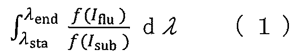
- step iv) formula (1) [Wherein, ⁇ sta is the short wavelength side of the fluorescence detection wavelength, ⁇ end is the long wavelength side of the fluorescence detection wavelength, f (I flu ) is the fluorescence intensity of the fluorescent molecule, and f (I sub ) is the fluorescence intensity of the substrate. ] 3. The method of embodiment 1 or 2, wherein the signal-to-noise ratio calculated by and selecting a fluorescence detection wavelength with a high signal-to-noise ratio.
- a nucleic acid sequence measurement device comprising a substrate, a fluorescent molecule, an excitation wavelength irradiation section, and a detection wavelength detection section, The device is set so that the substrate is used in a wavelength band where the substrate fluorescence is low, based on the three-dimensional fluorescence spectrum of the DNA microarray substrate obtained in advance,
- the excitation wavelength irradiator excites a wavelength in a wavelength band where the substrate fluorescence is low based on the three-dimensional fluorescence spectrum of the DNA microarray substrate obtained in advance
- the fluorescent molecule has a fluorescence wavelength in a wavelength band where the substrate fluorescence is low based on the three-dimensional fluorescence spectrum of the DNA microarray substrate obtained in advance
- the detection wavelength detection unit uses the fluorescence wavelength in the wavelength band where the substrate fluorescence is low based on the three-dimensional fluorescence spectrum of the DNA microarray substrate obtained in advance as the fluorescence detection wavelength.
- a DNA microarray detection device comprising a substrate, a fluorescent molecule, an excitation wavelength irradiation unit, and a detection wavelength detection unit,
- the apparatus is set so that the substrate is used in a wavelength band where the substrate fluorescence is low, based on the three-dimensional fluorescence spectrum of the DNA microarray substrate obtained in advance,
- the excitation wavelength irradiator excites a wavelength in a wavelength band where the substrate fluorescence is low based on the three-dimensional fluorescence spectrum of the DNA microarray substrate obtained in advance
- the fluorescent molecule has a fluorescence wavelength in a wavelength band where the substrate fluorescence is low based on the three-dimensional fluorescence spectrum of the DNA microarray substrate obtained in advance
- the detection wavelength detection unit uses the fluorescence wavelength in the wavelength band where the substrate fluorescence is low based on the three-dimensional fluorescence spectrum of the DNA microarray substrate obtained in advance as the fluorescence detection wavelength.
- the DNA microarray detection device uses the fluorescence wavelength in the
- S/N ratio signal/noise ratio
- the detection wavelength of the apparatus or device is predetermined, in the three-dimensional fluorescence spectrum of the substrate fluorescence of the two or more substrates, the predetermined employing a substrate that has low substrate fluorescence at the detection wavelength being used; including Further, manufacturing said apparatus or device using the employed substrate;
- step iv) formula (1) [Wherein, ⁇ sta is the short wavelength side of the fluorescence detection wavelength, ⁇ end is the long wavelength side of the fluorescence detection wavelength, f (I flu ) is the fluorescence intensity of the fluorescent molecule, and f (I sub ) is the fluorescence intensity of the substrate. ] 8. The method of embodiment 7, wherein the S/N ratio calculated by and employing a substrate with a high S/N ratio.
- a method for manufacturing a DNA microarray detection device or nucleic acid sequence measurement device by selecting a substrate with lower substrate fluorescence noise and using the selected substrate comprising: i) obtaining three-dimensional fluorescence spectra of two or more DNA microarray substrates; ii) comparing the substrate fluorescence of said two or more substrates; iii) a quality control step of integrating the substrate fluorescence of the two or more substrates and adopting a substrate with a relatively low integrated value; and iv) using the adopted substrate to manufacture the device or substrate;
- the above method comprising: i) obtaining three-dimensional fluorescence spectra of two or more DNA microarray substrates; ii) comparing the substrate fluorescence of said two or more substrates; iii) a quality control step of integrating the substrate fluorescence of the two or more substrates and adopting a substrate with a relatively low integrated value; and iv) using the adopted substrate to manufacture the device or substrate;
- step iii) formula (2) [Wherein, F is the integrated value, ⁇ ex is the excitation wavelength, ⁇ em is the fluorescence wavelength, and f (I sub ) is the fluorescence intensity of the substrate] 10.
- F is the integrated value
- ⁇ ex is the excitation wavelength
- ⁇ em is the fluorescence wavelength
- f (I sub ) is the fluorescence intensity of the substrate
- DNA can be detected at a high S/N ratio using a DNA microarray.
- the method of using the DNA microarray substrate enables observation of the DNA microarray under conditions of low substrate fluorescence.
- FIG. 4 is a diagram showing; A method of modifying a DNA probe described in Non-Patent Document 2 with a fluorescent molecule, immobilizing a target on the solid phase surface of a substrate, and binding the DNA probe modified with the fluorescent molecule to the target immobilized on the solid phase surface.
- FIG. 4 is a diagram showing; A method of modifying a DNA probe described in Non-Patent Document 2 with a fluorescent molecule, immobilizing a target on the solid phase surface of a substrate, and binding the DNA probe modified with the fluorescent molecule to the target immobilized on the solid phase surface.
- FIG. 4 is a diagram showing; Schematic diagram showing the hybridization reaction of the target 3 of the probe consisting of the donor fluorescent probe 6 modified with the fluorescent molecule 4 and the quenching probe 7 modified with the quenching molecule 8 of the nucleic acid sequence measurement device described in Patent Document 1. be.
- a protocol for detecting the hybridization reaction between the target 6 and the donor fluorescent probe 2 is shown.
- FIG. 4 shows a flow diagram of a method of using a DNA microarray substrate in a wavelength band where autofluorescence is low. The three-dimensional fluorescence spectrum of the substrate for DNA microarray is shown. A two-dimensional fluorescence spectrum of a DNA microarray substrate excited at 550 nm is shown.
- FIG. 10 compares two substrate fluorescences; Experimental values on the left, hypothetical examples on the right.
- FIG. 10 compares two substrate fluorescences; Experimental values on the left, hypothetical examples on the right.
- the present invention provides a method for designing a DNA microarray detection device.
- This method i) obtaining a three-dimensional fluorescence spectrum of the DNA microarray substrate and determining a wavelength band in which the substrate fluorescence is low. Furthermore, one or more steps selected from the group consisting of ii) to iv), ii) if the excitation wavelength of the DNA microarray detection device to be designed has not been determined in advance, the step of selecting an excitation wavelength corresponding to a wavelength band in which the substrate fluorescence is low in the three-dimensional fluorescence spectrum; iii) when the fluorescent molecules to be used in the DNA microarray detection device to be designed have not been determined in advance, a step of selecting fluorescent molecules having a fluorescence wavelength in a wavelength band where the substrate fluorescence is low in the three-dimensional fluorescence spectrum; selecting a fluorescence wavelength in a wavelength band in which the substrate fluorescence is low in the fluorescence spectrum as the fluorescence detection wavelength; can include The method may further include
- Step ii) can be omitted if the excitation wavelength of the DNA microarray detection device to be designed is predetermined. Moreover, step iii) can be omitted if the fluorescent molecules to be used in the DNA microarray detection device to be designed are determined in advance.
- a three-dimensional fluorescence spectrum is a measured fluorescence spectrum expressed in three dimensions: excitation wavelength, fluorescence wavelength, and fluorescence intensity. It can be obtained by conventional methods. For example, the fluorescence spectrum is measured with the excitation wavelength fixed, and when the fluorescence spectrum scanning is completed, the fluorescence wavelength is returned to the measurement start wavelength, the excitation wavelength is driven by a predetermined wavelength interval, and the fluorescence spectrum is measured at the next excitation wavelength. do. Repeat this operation for the wavelength range of interest.
- a three-dimensional fluorescence spectrum is obtained by representing the obtained fluorescence spectrum in three dimensions of excitation wavelength, fluorescence wavelength, and fluorescence intensity.
- Spectral data acquisition intervals can be, for example, 1 nm intervals, 2 nm intervals, 3 nm intervals, 4 nm intervals, 5 nm intervals, 6 nm intervals, 7 nm intervals, 8 nm intervals, 9 nm intervals, and, for example, 10 nm intervals, but are not limited thereto.
- the wavelength band with low substrate fluorescence refers to the wavelength band with low substrate autofluorescence, where 100 is the most intense point among all valid measurement points of substrate fluorescence, and the most It can be a continuous wavelength region consisting of wavelengths less than the geometric mean when the weak measurement point is 0.
- all effective measurement points here mean all effective measurement points excluding outliers, abnormal values, and values caused by leakage of excitation light from all measurement points.
- excitation light leaks into the short wavelength side of the fluorescence spectrum, and very large values may be measured. Therefore, unless otherwise specified, the wavelength range affected by the leakage of excitation light is excluded from effective measurement points.
- the measured data can be statistically processed.
- a data set can be used in which the acquired data is sorted in ascending order (descending order) and the high data is removed.
- a data set with statistically abnormal high values removed can be used.
- a statistically abnormal value can be determined, for example, by the Grubbs-Smirnov rejection test (also called Grubb's test).
- Grubbs-Smirnov rejection test also called Grubb's test.
- values that are two standard deviations above or below the mean may be rejected as outliers.
- values that are three standard deviations above or below the mean may be rejected as outliers.
- a continuous wavelength region consisting of wavelengths less than the arithmetic mean, less than the geometric mean, or less than the median when the point with the strongest intensity among all measurement points of substrate fluorescence is set to 100 and the weakest measurement point is set to 0
- a lower wavelength region can be selected from among the multiple regions.
- the continuous wavelength region is, for example, a difference of 5 nm or more between a short wavelength and a long wavelength, a difference of 10 nm or more, a difference of 20 nm or more, a difference of 30 nm or more, a difference of 40 nm or more, a difference of 50 nm or more, or 300 nm.
- a difference of 200 nm or less a difference of 150 nm or less, a difference of 100 nm or less, a difference of 90 nm or less, a difference of 80 nm or less, a difference of 70 nm or less, a difference of 60 nm or less, a difference of 50 nm or less, for example in the range of 5 nm to 300 nm a difference in the range of 10 nm to 200 nm, a difference in the range of 20 nm to 150 nm, a difference in the range of 30 nm to 100 nm, a difference in the range of 40 nm to 90 nm, a difference in the range of 50 nm to 80 nm, such as a difference in the range of 60 nm to 70 nm.
- the short wavelength and long wavelength of fluorescence can be appropriately selected from the range of 200-800 nm, 300-750 nm, 350-750 nm, eg, 360-750 nm.
- the short wavelength and long wavelength of the excitation light can be appropriately selected from the range of 200-800 nm, 300-750 nm, 340-740 nm, eg, 350-730 nm.
- the present invention provides a method for manufacturing a DNA microarray detection device.
- This method i) obtaining a three-dimensional fluorescence spectrum of the DNA microarray substrate and determining a wavelength band in which substrate fluorescence is low, and further comprising one or more steps selected from the group consisting of ii) to iv); ii) if the excitation wavelength of the DNA microarray detection device to be designed has not been determined in advance, the step of selecting an excitation wavelength corresponding to a wavelength band in which the substrate fluorescence is low in the three-dimensional fluorescence spectrum; iii) when the fluorescent molecules to be used in the DNA microarray detection device to be designed have not been determined in advance, a step of selecting fluorescent molecules having a fluorescence wavelength in a wavelength band where the substrate fluorescence is low in the three-dimensional fluorescence spectrum; selecting a fluorescence wavelength in a wavelength band in which the substrate fluorescence is low in the fluorescence spectrum as the fluorescence detection wavelength; can include Furthermore, this method
- Step ii) can be omitted if the excitation wavelength of the DNA microarray detection device to be designed is predetermined. Moreover, step iii) can be omitted if the fluorescent molecules to be used in the DNA microarray detection device to be designed are determined in advance.
- the present invention provides a nucleic acid sequence measurement device comprising a substrate, a fluorescent molecule, an excitation wavelength irradiation section, and a detection wavelength detection section.
- the device can be set so that the substrate is used in a low wavelength band of substrate fluorescence.
- the excitation wavelength irradiator may excite a wavelength in a wavelength band in which the substrate fluorescence is low, based on the three-dimensional fluorescence spectrum of the DNA microarray substrate obtained in advance.
- the fluorescent molecule may have a fluorescence wavelength in a wavelength band in which the substrate fluorescence is low based on the three-dimensional fluorescence spectrum of the DNA microarray substrate obtained in advance.
- the detection wavelength detection unit may detect a fluorescence wavelength in a wavelength band where the substrate fluorescence is low based on the three-dimensional fluorescence spectrum of the DNA microarray substrate obtained in advance.
- the present invention provides a DNA microarray detection device comprising a substrate, fluorescent molecules, an excitation wavelength irradiation section, and a detection wavelength detection section.
- the apparatus can be set so that the substrate is used in a low wavelength band of substrate fluorescence.
- the excitation wavelength irradiator may excite a wavelength in a wavelength band in which the substrate fluorescence is low, based on the three-dimensional fluorescence spectrum of the DNA microarray substrate obtained in advance.
- the fluorescent molecule may have a fluorescence wavelength in a wavelength band in which the substrate fluorescence is low based on the three-dimensional fluorescence spectrum of the DNA microarray substrate obtained in advance.
- the detection wavelength detection unit may detect a fluorescence wavelength in a wavelength band where the substrate fluorescence is low based on the three-dimensional fluorescence spectrum of the DNA microarray substrate obtained in advance.
- the present invention provides a method of selecting a substrate with a higher signal/noise ratio (S/N ratio) and manufacturing a DNA microarray detection device or nucleic acid sequence measurement device using the selected substrate.
- This method i) obtaining three-dimensional fluorescence spectra of two or more substrates, and ii) comparing the substrate fluorescence of said two or more substrates; and further one or more steps selected from the group consisting of iii) to v); iii) when the excitation wavelength of the apparatus or device is predetermined, among the substrate fluorescence of the two or more substrates, a substrate having a low substrate fluorescence at the predetermined excitation wavelength in the three-dimensional fluorescence spectrum; the process to adopt, iv) When the fluorescent molecules used in the apparatus or device are predetermined, among the substrate fluorescence of the two or more substrates, the three-dimensional fluorescence spectrum corresponds to the fluorescence wavelength of the predetermined fluorescent molecule.
- Step iii)-v) may be performed according to flow diagram 5. It should be noted that if the results of the substrates to be employed differ between steps iii) to v), step v) takes precedence, followed by step iv).
- the signal/noise ratio (S/N ratio) is expressed by formula (1) [Wherein, ⁇ sta is the short wavelength side of the fluorescence detection wavelength, ⁇ end is the long wavelength side of the fluorescence detection wavelength, f (I flu ) is the fluorescence intensity of the fluorescent molecule, and f (I sub ) is the fluorescence intensity of the substrate. ] can be calculated by In the method, device or apparatus of the present invention, fluorescence detection wavelengths with high S/N ratios can be selected. ⁇ sta and ⁇ end can be set appropriately.
- the present invention provides a method of selecting a substrate with lower substrate fluorescence noise and manufacturing a DNA microarray detection device or nucleic acid sequence measurement device using the selected substrate.
- This manufacturing method i) obtaining three-dimensional fluorescence spectra of two or more DNA microarray substrates; ii) comparing the substrate fluorescence of said two or more substrates; iii) a quality control step of integrating the substrate fluorescence of the two or more substrates and adopting a substrate with a relatively low integrated value; and iv) using the adopted substrate to manufacture the device or substrate; can include In certain embodiments, in step iii), formula (2) [Wherein, F is the integrated value, ⁇ ex is the excitation wavelength, ⁇ em is the fluorescence wavelength, and f (I sub ) is the fluorescence intensity of the substrate] Substrate fluorescence can be integrated by . In a specific embodiment, the integrated value F may be calculated by integrating over a wavelength range excluding the substrate reflection noise of the substrate
- FIG. 5 shows the flow of the method of using the DNA microarray substrate used in the embodiment of the present invention.
- a method of using the DNA microarray substrate first, the three-dimensional fluorescence spectrum of the excitation wavelength, fluorescence wavelength, and fluorescence intensity of the DNA microarray substrate is obtained (S17). It is determined whether or not the excitation wavelength to be used is determined according to the convenience of the apparatus (S18).
- an excitation wavelength that does not emit fluorescence is selected from the three-dimensional fluorescence spectrum of the substrate (S20), then a fluorescent molecule to be used in the DNA microarray that can be excited at the excitation wavelength is selected (S21), After that, the fluorescence detection wavelength is selected so as to detect the fluorescence wavelength band of the fluorescent molecule to be used (S22).
- the excitation wavelength to be used it is determined whether the fluorescent molecules to be used have been determined (S19).
- the excitation wavelength to be used is determined and the fluorescent molecule to be used is not determined, the two-dimensional spectrum of the fluorescence wavelength and fluorescence intensity corresponding to the determined excitation wavelength is confirmed from the three-dimensional fluorescence spectrum.
- a fluorescent molecule that emits fluorescence in a wavelength band with low substrate fluorescence is selected from the two-dimensional spectrum (S21), and then a fluorescence detection wavelength is selected so as to detect the fluorescence wavelength band of the fluorescent molecule to be used (S22).
- the excitation wavelength to be used is determined and the fluorescent molecule to be used is determined, the two-dimensional spectrum of the fluorescence wavelength and fluorescence intensity of the substrate and the fluorescent molecule corresponding to the determined excitation wavelength is confirmed from the three-dimensional fluorescence spectrum.
- the fluorescence intensity of the substrate to be used and the fluorescence intensity of the fluorescent molecule are confirmed, and the fluorescence detection wavelength is selected so as to detect the wavelength band in which the fluorescence intensity of the substrate is low and the fluorescence intensity of the fluorescent molecule is high (S22).
- FIG. 6 shows a three-dimensional fluorescence spectrum of a slide glass for DNA immobilization.
- the horizontal axis indicates the fluorescence wavelength (nm)
- the vertical axis indicates the excitation wavelength (nm)
- the grayscale of the brightness of the image indicates the fluorescence intensity, and the whiter the fluorescence intensity, the higher the fluorescence intensity.
- Acquisition of the three-dimensional fluorescence spectrum was performed by JASCO Corporation FP-8500.
- the wavelength range is the fluorescence intensity obtained by scanning the fluorescence wavelength of 360 to 750 nm at the excitation wavelength of 350 to 730 nm, and the spectral data acquisition interval is 5 nm.
- the fluorescence is strong in a wide range at an excitation wavelength of 370 nm or less. This is because each material of the substrate generally exhibits high fluorescence when excited in the ultraviolet region.
- a high fluorescence region was observed around a fluorescence wavelength of 500 to 570 nm at an excitation wavelength of 370 to 450 nm, and a high fluorescence region was observed around 590 to 700 nm at an excitation wavelength of 530 to 620 nm. Wavelength regions can be identified.
- an excitation wavelength with low fluorescence intensity can be selected from the three-dimensional fluorescence spectrum of the substrate shown in FIG. 6 or a corresponding one.
- the excitation light source for example, a laser light source that emits single-wavelength laser light or its expanded light, an LED (Light Emitting Diode), a lamp that emits white light, a light source consisting of a combination of an LED and a wavelength filter, etc. can be used.
- a bandpass filter is used to cut out only the wavelength region corresponding to the excitation wavelength, but the light in the wavelength band that is originally cut by the filter is cut due to the imperfection of the filter's opacity. If the wavelength of the transmitted excitation light overlaps with the fluorescence wavelength, it becomes a factor of background light. It is often done.
- wavelengths are selected from commercially available products because the wavelengths available on the market are limited.
- the excitation wavelength to be used is determined in advance and the fluorescent molecule to be used is not determined, the two-dimensional spectrum of the fluorescence wavelength and fluorescence intensity corresponding to the determined excitation wavelength is confirmed from the three-dimensional fluorescence spectrum.
- fluorescent molecules that emit fluorescence in a wavelength band where the substrate fluorescence is low can be selected (S21). As a result, detection can be performed with a high S/N ratio in a region where the fluorescence of the substrate is low.
- the fluorescence detection wavelength can be freely selected within the range in which the fluorescence wavelength of the fluorescent molecule can be detected.
- the excitation wavelength to be used is determined in advance and the fluorescent molecule to be used is determined, check the two-dimensional spectrum of the fluorescence wavelength and fluorescence intensity of the substrate and the fluorescent molecule corresponding to the determined excitation wavelength from the three-dimensional fluorescence spectrum. .
- a two-dimensional spectrum of a fluorescent molecule can be obtained with the spectrofluorometer.
- a certain fluorescent molecule e.g., Cy3 molecule, Bioconjugate Chem. 1993, 4, 2, 105-111
- acquire a two-dimensional fluorescence spectrum of the relative fluorescence intensity of the substrate and the fluorescent molecule at the excitation wavelength of the fluorescent molecule Then, examine the region where the fluorescence intensity of the substrate is low and the fluorescence intensity of the fluorescent molecules is high.
- the fluorescence detection wavelength is selected so that the wavelength band in which the fluorescence intensity of the substrate is low and the fluorescence intensity of the fluorescent molecules is high is detected (S22).
- detection can be performed with a high S/N ratio in a region where the fluorescence of the substrate is low.
- the S/N ratio can be confirmed by the following equation (1).
- ⁇ sta is the short wavelength side of the fluorescence detection wavelength
- ⁇ end is the long wavelength side of the fluorescence detection wavelength
- f (I flu ) is the fluorescence intensity of the fluorescent molecule
- f (I sub ) is the fluorescence intensity of the substrate.
- the selected fluorescence detection wavelength can be achieved with any bandpass, shortpass, or longpass filter.
- a well-known filter can be used for various filters.
- the present invention as a method of using a DNA microarray substrate, it is possible to select an excitation wavelength optimized for a region with low substrate fluorescence in order to increase detection sensitivity. Moreover, the present invention makes it possible to select fluorescent molecules to be used in regions where substrate fluorescence is low in order to increase detection sensitivity. Further, according to the present invention, it is possible to select a fluorescence detection wavelength in a wavelength range in which substrate fluorescence is low and fluorescence intensity of fluorescent molecules is high in order to increase detection sensitivity. Also, according to the present invention, DNA spots on a DNA microarray can be detected at a high S/N ratio.
- the present invention can be used in a nucleic acid sequence measurement device in which a signal generation source such as a fluorescent molecule is modified in a probe immobilized on a substrate in a DNA microarray or the like.
- a signal generation source such as a fluorescent molecule
- the present invention can be used for unmodified target detection by signaling array probes. It can be used in the method of
- the present invention can be used in a method for selecting fluorescent molecules for the nucleic acid sequence measurement device.
- the present invention can be used for a method of selecting a fluorescence detection wavelength of the microarray detection device of the nucleic acid sequence measurement device.
- the present invention provides a nucleic acid sequence measurement device that captures and observes target molecules in which a signal generation source such as a fluorescent molecule is modified by a probe immobilized on a substrate in a DNA microarray or the like.
- a signal generation source such as a fluorescent molecule
- the present invention is a DNA microarray or the like, in which a target molecule is bound to a probe solid-phase-immobilized on a substrate with a labeling molecule modified with a signal-generating source such as a fluorescent molecule that specifically binds to the target molecule.
- the present invention provides a method of selecting an excitation wavelength for a microarray detector of a device for measuring nucleic acid sequences. In one embodiment, the present invention provides a method for selecting fluorescent molecules for the nucleic acid sequence measurement device. In one embodiment, the present invention provides a method for selecting the fluorescence detection wavelength of the bioarray detector of the device for nucleic acid sequence measurement.
- the present invention can be used for a dye selection method for a DNA microarray method, a nucleic acid sequence measurement device based on a DNA microarray method, and a biomolecule measurement device based on a fluorescence detection method.
- the present invention can be applied to a biomolecule measuring device based on the principle of designing the excitation wavelength and fluorescence detection wavelength band of a DNA microarray detection device, the DNA microarray detection device, and other fluorescence detection methods.
- the present invention can be used for dry image measurement in fluorescence measurement, observation of biochip fluorescence in liquid, and real-time observation in continuous reaction.
- the device, apparatus, and kit manufactured by the manufacturing method of the present invention can also be applied to solid-phase methods such as labeled antibody methods used in clinical tests and the like. Examples include, but are not limited to, the FISH method (fluorescence in situ hybridization), in which the expression of specific chromosomes or genes in tissues or cells is fluorometrically measured using a fluorescent substance.
- FISH method fluorescence in situ hybridization
- the present invention employs the FIA method (fluorescent immunoassay) for measuring antigen-antibody reaction using a fluorescent substance as a label, and the IFA method for measuring serum (antibody) reaction by labeling pathogens that serve as antigens with a fluorescent substance. method (indirect immunofluorescence method).
- Any target can be used as long as it can be detected in a sample, and examples include, but are not limited to, nucleic acids such as DNA and RNA, peptides, and proteins.
- Capture molecules that specifically bind to targets include detection probes that hybridize with nucleic acids, antibodies or antibody fragments that specifically bind to antigens such as peptides and proteins, and aptamers that specifically bind to nucleic acids. is not limited to this.
- Examples of antibodies include, but are not limited to, polyclonal antibodies, monoclonal antibodies, chimeric antibodies, human antibodies, humanized antibodies, and antibody fragments.
- Antibody fragments include, for example, F(ab')2, F(ab)2, Fab', Fab, scFv, Fv, variants thereof, fusion proteins or fusion peptides containing antigen-binding portions or antibody portions, and the like. is not limited to this.
- the target may be an antibody or antibody fragment and the capture molecule may be an antigen such as a peptide, protein, etc. that specifically binds to the antibody or antibody fragment.
- Combinations of a target and a capture molecule that specifically binds to the target include, for example, a detection method in which the target is a nucleic acid having a specific nucleic acid sequence and the capture molecule has a nucleic acid sequence complementary to the specific nucleic acid sequence.
- Examples include, but are not limited to, combinations that are probes, combinations where the target is an antigen and the capture molecule is an antibody or antibody fragment that specifically binds to the antigen.
- the target is a nucleic acid having a specific nucleic acid sequence and the capture molecule is a detection probe having a nucleic acid sequence complementary to the specific nucleic acid sequence
- the target nucleic acid hybridizes with the capture molecule, the detection probe.
- Hybridization can be performed under stringent conditions.
- the term "complementary" means that one nucleic acid sequence has a nucleic acid sequence capable of forming a double-stranded state with the other nucleic acid sequence, and both sequences are not necessarily completely complementary. need not be and may contain several mismatched base pairs.
- hybridization can be performed under stringent conditions such that the target nucleic acid and the detection probe hybridize even if they contain such mismatched base pairs.
- the device or apparatus may further comprise a quenching molecule (also called a quencher).
- a quenching molecule also called a quencher.
- the quenching molecule can be arranged appropriately so that when the quenching molecule approaches the fluorescent molecule, the fluorescence exhibited by the fluorescent molecule is quenched.
- Any fluorescent molecule may be used as long as it is excited by a specific excitation light and emits fluorescence.
- quenching molecules examples include TQ1, Dabcyl, TQ2, TQ3, Eclipse (registered trademark), BHQ1, BHQ2, BHQ3, Cy5Q, Cy7Q, Iowa Black (registered trademark) FQ, Iowa Black (registered trademark) RQ, IRDye QC- 1, QSY7, QSY21, QXL570, NBD (7-nitrobenzofuran) and other known quenchers, but not limited thereto.
- fluorescent and quenching molecules may be used, such as FAM, FITC, TET, Alexa Fluor® 532, Cy2, Cy3, TF2 or TF3 in combination with TQ2, EDANS, Coumarin or TF2 in combination with Dabcyl or TQ1, Alexa Fluor® 532, Cy3, HEX, JOE, TF2, TF3, TF4 or TET in combination with TQ3, Alexa Fluor® 532, TF2, Cy3, FAM or HEX with Eclipse®, Alexa Fluor® 532, TF2, TF3, Cy3, FAM, HEX, TET or Cy3 with BHQ1, TF3, TF4, Cy3, Cy5 or HEX with BHQ2 with, Cy5, Alexa Fluor® 647, TF5 with Iowa Black® RQ, IRDye QC-1, QSY21, TQ4, TQ5, BHQ2 or BHQ3, Cy3, TF3, TF4 with Cy5Q, Iowa Black® FQ, Iowa Black® RQ, IRDye
- quartz, glass, silicon, single crystals such as calcium fluoride and sapphire, ceramics, resin materials, etc. can be used, but not limited to these.
- the resin material include, but are not limited to, COP (cycloolefin polymer), COC (cyclic olefin copolymer), polycarbonate, acrylic resin, and polyethylene resin, which are excellent in optical properties and chemical and thermal stability. do not have.
- the shape of the substrate when viewed from above may be any shape, such as a polygonal, rectangular, square, or rectangular shape.
- the substrate material may be, for example, a plate-like material having a rectangular shape when viewed from above.
- the present invention provides a kit for DNA microarray detection or nucleic acid sequence measurement.
- the kit can include a DNA microarray detection device or nucleic acid sequence measurement device equipped with an excitation wavelength irradiation unit and a fluorescence wavelength detection unit, a substrate, fluorescent molecules, and instructions for use. Kits may also optionally include quenching molecules, reagents necessary for measurement, such as standard solutions, buffer solutions, detection probes, and capture molecules. These can be those mentioned above.
- Example 1 (Acquisition of three-dimensional fluorescence spectrum (S17)) A three-dimensional fluorescence spectrum of the slide glass for DNA immobilization was obtained.
- the slide glass As the slide glass, the catalog number SDA0011 manufactured by Matsunami Glass Industry Co., Ltd. was used.
- As an excitation light source a xenon lamp of a fluorescence spectrophotometer FP-8500 manufactured by JASCO Corporation was used. Acquisition of the three-dimensional fluorescence spectrum was performed by JASCO Corporation FP-8500.
- the wavelength range is the fluorescence intensity obtained by scanning the fluorescence wavelength of 360 to 750 nm at the excitation wavelength of 350 to 730 nm, and the data acquisition interval was 5 nm. The results are shown in FIG.
- the horizontal axis indicates the fluorescence wavelength (nm)
- the vertical axis indicates the excitation wavelength (nm)
- the grayscale of the brightness of the image indicates the fluorescence intensity, and the whiter the fluorescence intensity, the higher the fluorescence intensity.
- the excitation wavelength can be selected based on the three-dimensional fluorescence spectrum measurement results of FIG. 6 or equivalents.
- an excitation wavelength or a region where the fluorescence intensity of the substrate is low can be selected based on the three-dimensional fluorescence spectrum of the substrate. For example, from the three-dimensional fluorescence spectrum of the substrate of this example, the fluorescence intensity is low when excited at an excitation wavelength of 500 to 540 nm, and by selecting the excitation wavelength in this wavelength band, the S / N is high in the region where the fluorescence of the substrate is low. Detection becomes possible.
- Fluorescent molecules that are excitable at the excitation wavelength can be freely selected according to the excitation wavelength determined by the excitation wavelength selection step.
- the excitation wavelength to be used is determined in advance and the fluorescent molecule to be used is not determined, the two-dimensional spectrum of the fluorescence wavelength and fluorescence intensity corresponding to the determined excitation wavelength is confirmed from the three-dimensional fluorescence spectrum.
- a method for selecting fluorescent molecules when using a commercially available green solid-state laser with an oscillation wavelength of 550 nm will be described.
- a two-dimensional fluorescence spectrum at an excitation wavelength of 550 nm was extracted from the three-dimensional fluorescence spectrum shown in FIG. 6 and shown in FIG.
- fluorescence is lower around 700 nm than around 600 nm, and a fluorescent molecule that emits fluorescence in a wavelength band where substrate fluorescence is low can be selected (S21).
- S21 a fluorescent molecule that emits fluorescence in a wavelength band where substrate fluorescence is low.
- the fluorescence detection wavelength can be freely selected within the range in which the fluorescence wavelength of the fluorescent molecule can be detected.
- the excitation wavelength to be used is determined in advance and the fluorescent molecule to be used is determined, check the two-dimensional spectrum of the fluorescence wavelength and fluorescence intensity of the substrate and the fluorescent molecule corresponding to the determined excitation wavelength from the three-dimensional fluorescence spectrum. .
- a two-dimensional spectrum of a fluorescent molecule can be obtained with the spectrofluorometer.
- selection of the fluorescence detection wavelength when using a commercially available green solid-state laser with an oscillation wavelength of 550 nm and a Cy3 molecule with a maximum excitation wavelength of 550 nm (modified during oligo-DNA custom synthesis) generally used in biomeasurement. Describe the method.
- the fluorescence of the substrate is relatively strong in the detection wavelength band of 605 to 620 nm, and the fluorescence of the fluorescent molecules is only slightly stronger than the wavelength regions before and after it. However, such a range may not be used.
- the S/N ratio between the fluorescence intensity of the fluorescent molecule and the fluorescence intensity of the substrate can be calculated by the following equation (1). [Wherein, ⁇ sta is the short wavelength side of the fluorescence detection wavelength, ⁇ end is the long wavelength side of the fluorescence detection wavelength, f (I flu ) is the fluorescence intensity of the fluorescent molecule, and f (I sub ) is the fluorescence intensity of the substrate. ].
- the selected fluorescence detection wavelength can be achieved with any bandpass, shortpass, or longpass filter.
- Example 2 A hypothetical example comparing the three-dimensional fluorescence spectra of two DNA microarray substrates is shown in FIG. The left is the result of Example 1 and the right is a hypothetical example.
- the three-dimensional fluorescence spectra of two DNA microarray substrates are compared and the excitation wavelengths are determined in advance, the three-dimensional fluorescence spectra of the substrate fluorescence of the two substrates are Substrates with low substrate fluorescence at a predetermined excitation wavelength can be employed.
- the excitation wavelength is around 420 nm
- the right substrate can be used, and if the excitation wavelength is around 580 nm, the left substrate can be used.
- the substrate fluorescence in the region corresponding to the fluorescence wavelength of the predetermined fluorescent molecule in the three-dimensional fluorescence spectrum of the substrate fluorescence of the two substrates is A low substrate can be employed.
- the maximum fluorescence wavelength of the fluorescent molecules is around 510 nm
- the right substrate can be used
- the maximum fluorescence wavelength of the fluorescent molecules is around 720 nm
- the left substrate can be used.
- the excitation wavelength is adjusted so that the substrate fluorescence in the region corresponding to the fluorescence wavelength of the predetermined fluorescent molecule is low, taking into consideration the autofluorescence of the substrate. can be selected.
- an excitation wavelength of 450 to 500 nm can be selected for the left substrate, and 390 to 500 nm for the right substrate. of excitation wavelengths can be selected.
- the detection wavelength is predetermined, it is possible to adopt a substrate with low substrate fluorescence at the predetermined detection wavelength in the three-dimensional fluorescence spectrum among the substrate fluorescence of the two substrates. .
- the detection wavelength is around 510 nm
- the right substrate can be used
- the detection wavelength is around 720 nm
- the left substrate can be used.
- the employed substrate can be used to manufacture the apparatus or device.
- Example 3 A hypothetical example comparing the three-dimensional fluorescence spectra of two DNA microarray substrates is shown in FIG. The left is the result of Example 1 and the right is a hypothetical example. In this way, the three-dimensional fluorescence spectra of two DNA microarray substrates are compared, the substrate fluorescence of each substrate is integrated, and a substrate with a relatively low integrated value can be adopted. Also, the adopted substrate can be used to manufacture a DNA microarray detection device or a nucleic acid sequence measurement device.
Abstract
高いシグナル/ノイズ比にてDNAスポットを検出することができるDNAマイクロアレイ用の装置又はデバイスを提供することを目的とする。 DNAマイクロアレイ用基板の3次元蛍光スペクトルを取得し、基板蛍光が低い波長帯を決定し、それに基づき励起波長、蛍光分子、及び/又は検出波長を選択することを含む、DNAマイクロアレイ検出装置の製造方法等が提供される。
Description
本発明は、DNAマイクロアレイを用いて特定の核酸の有無や量を計測する核酸配列計測デバイスに関する。また本発明は、DNAマイクロアレイ用基板の使用方法及び評価方法に関する。また本発明は、DNAマイクロアレイを用いて特定の核酸の有無や量を計測する核酸配列計測デバイスのマイクロアレイ検出装置及びその製造方法に関する。
サンプルに含まれる特定の核酸配列を有するターゲットを計測する方法として、DNAマイクロアレイ(上記特定の核酸配列の相補配列を有する検出プローブが基板等の固相面に設けられたもの)を用いる方法が広く知られている。この方法は、DNAマイクロアレイに添加されたサンプルに含まれるターゲットが、ハイブリダイズ反応よりDNAマイクロアレイの検出プローブに捕集される性質を利用してターゲットを計測する方法である。この方法では、ターゲットがサンプルに含まれるか否かに加えて、サンプルに含まれるターゲットの量を計測することができる。
非特許文献1及び2には、DNAマイクロアレイを用いてターゲットを計測する従来の計測方法が開示されている。図1は非特許文献1に記載のターゲットを蛍光分子(蛍光物質ともいう)で修飾し、基板の固相面にDNAプローブを固定化し、蛍光分子で修飾されたターゲットを固相面に固定化されたDNAプローブに結合させる方法を示す図である。DNAプローブはリンカーを介してDNAマイクロアレイに固定されている。DNAプローブとターゲット分子との塩基対形成により、DNAマイクロアレイ上にターゲット分子が補足され、蛍光が検出可能となる。
図2は非特許文献2に記載のDNAプローブを蛍光分子で修飾し、基板の固相面にターゲットを固定化し、蛍光分子で修飾されたDNAプローブを固相面に固定化されたターゲットに結合させる方法を示す図である。この方法ではターゲット分子がDNAマイクロアレイ上に固定され、標識化されたDNAプローブが溶液側に存在する。DNAプローブとターゲット分子との塩基対形成により、DNAマイクロアレイ上にDNAプローブが補足され、蛍光が検出可能となる。非特許文献1及び2に記載のターゲット計測方法ではDNAマイクロアレイの基板蛍光(基板自家蛍光ともいうことがある)が検出時の背景光となりDNAスポット検出のシグナル/ノイズ比(S/N比)の低下を招くという問題があった。
特許文献1には、検出プローブとして、蛍光分子が付加された蛍光プローブと、蛍光分子の蛍光を消光する消光分子が付加された消光プローブとが設けられた核酸配列計測デバイス(DNAマイクロアレイ)を用いてターゲットを計測する方法が開示されている。その方法を図3に例示する。まず、DNAマイクロアレイ上に、蛍光分子で標識されたドナー蛍光プローブと、消光分子を有する消光プローブとが互いに独立して固定化され、結合部を介して互いに結合を形成し維持している。当該結合により、蛍光分子と消光分子とが接近し、蛍光は消光される。ここに、ターゲット分子が供給された場合、検出配列との塩基対形成により、消光プローブとドナー蛍光プローブとの結合が解消され、消光プローブに代わって、ターゲット分子がドナー蛍光プローブと塩基対形成する。消光物質がドナー蛍光分子から離れることにより、ドナー蛍光分子が蛍光を呈するようになる。開示されている方法では、ターゲットに対する蛍光分子の付加、及びDNAマイクロアレイの洗浄(捕集されていないターゲット等を除去するための洗浄)を行うことなくターゲットを計測することが可能である。
図3は特許文献1に記載の核酸配列計測デバイスの蛍光分子4が修飾されたドナー蛍光プローブ6と消光分子8が修飾された消光プローブ7からなるプローブのターゲット3のハイブリダイズの反応を示した模式図である。また図4はターゲットとドナー蛍光プローブのハイブリダイズの反応を検出するプロトコルを示す。図3において結合部22で結合したドナー蛍光プローブ6と消光プローブ7がリンカー21を介してDNAマイクロアレイ5に固定されている。核酸配列計測デバイスの動作としては、ドナー蛍光プローブ6と消光プローブ7とが結合している間は消光分子8によりドナー蛍光分子4の蛍光が消光された状態になっており、ハイブリダイゼーション反応によりドナー蛍光プローブ6の検出配列2にターゲット3が結合して消光プローブ7が離れると蛍光を呈する。そのためハイブリダイズ未反応の分子の洗浄操作が不要で、DNAマイクロアレイ5の蛍光画像を取得し蛍光光量を算出することでハイブリダイズ反応したターゲット3の分子を検出することができる。
平山幸一ら、UGT1A1の遺伝子多型を判別するDNAチップキットの開発、東洋鋼鈑 Vol.38,51-56,2015
Vivian G. C., et al. Making and reading microarrays, Nature genetics supplement 21, 15-19 (1999)
特許文献1の核酸配列計測方法は、捕集されていないターゲットを除去するための洗浄操作を必要とせず、それゆえ洗浄操作により計測精度が悪化することはない。しかしながら、特許文献1の核酸配列計測方法では、作製したDNAマイクロアレイから発せられるオフセット光がノイズとなって計測精度を悪化させてしまうことがあるという問題がある。
特許文献1に記載の核酸配列計測方法ではターゲット非修飾で検出が可能であるため、溶液の自家蛍光を上げることなく非洗浄でDNAマイクロアレイの観察が可能であるが、基板自体の自家蛍光について考慮されていない。
本発明は、上記事情に鑑みてなされたものであり、DNAマイクロアレイを観察するときに、高いシグナル/ノイズ比にてDNAスポットを検出することができるDNAマイクロアレイ用基板を備えた核酸配列計測デバイス又はDNAマイクロアレイ検出装置及びその製造方法を提供することを目的とする。
また本発明は、DNAマイクロアレイを観察するときに、DNAスポットの検出ノイズを低減し微弱光を計測可能とする方法及び装置を提供することを目的とする。
本発明者らは、前記課題解決のために鋭意研究を重ねた結果、DNAマイクロアレイでの蛍光測定時に、特定の励起波長、蛍光分子、及び検出波長を用いた場合に、これと異なる励起波長、蛍光分子、又は検出波長を用いた場合と比較して、シグナル/ノイズ比が予想外に変化することを確認した。本発明者らは、さらに研究を重ね、DNAマイクロアレイ用基板そのものの3次元蛍光スペクトルを取得したところ、基板蛍光が高い波長帯(領域)及び基板蛍光が低い波長帯(領域)が存在することを確認した。そこで本発明者らは、DNAマイクロアレイでの蛍光測定における、基板蛍光による測定結果への影響を回避することにより、上記課題を解決し得ることを見出し、これを一実施形態として包含する本発明を完成した。
特定の実施形態において、例示するならば、基板蛍光が低い波長帯での蛍光検出、及び/又は基板蛍光が低い波長帯に蛍光波長を有する蛍光分子を使用すること、及び/又は基板蛍光が低い波長帯に対応する励起波長を用いること、により基板蛍光による測定結果への影響を回避することができるが、本発明はこれらの実施形態に限られない。
本発明は、以下の実施形態を包含する。
[1] DNAマイクロアレイ検出装置の設計方法であって、
i)DNAマイクロアレイ用基板の3次元蛍光スペクトルを取得し、基板蛍光が低い波長帯を決定する工程を含み、
さらにii)~iv)からなる群より選択される1以上の工程、
ii)設計するDNAマイクロアレイ検出装置の励起波長が予め決定されていない場合は、3次元蛍光スペクトルにおいて基板蛍光が低い波長帯に対応する励起波長を選択する工程、
iii)設計するDNAマイクロアレイ検出装置に使用する蛍光分子が予め決定されていない場合は、3次元蛍光スペクトルにおいて基板蛍光が低い波長帯に蛍光波長を有する蛍光分子を選択する工程、及び
iv)3次元蛍光スペクトルにおいて基板蛍光が低い波長帯の蛍光波長を蛍光検出波長として選択する工程、
を含み、さらに、
v)選択した蛍光波長、蛍光分子、及び/又は蛍光検出波長に基づき、DNAマイクロアレイ検出装置を設計する工程、
を含む、DNAマイクロアレイ検出装置の設計方法。
[2] DNAマイクロアレイ検出装置の製造方法であって、
i)DNAマイクロアレイ用基板の3次元蛍光スペクトルを取得し、基板蛍光が低い波長帯を決定する工程を含み、
さらにii)~iv)からなる群より選択される1以上の工程、
ii)設計するDNAマイクロアレイ検出装置の励起波長が予め決定されていない場合は、3次元蛍光スペクトルにおいて基板蛍光が低い波長帯に対応する励起波長を選択する工程、
iii)設計するDNAマイクロアレイ検出装置に使用する蛍光分子が予め決定されていない場合は、3次元蛍光スペクトルにおいて基板蛍光が低い波長帯に蛍光波長を有する蛍光分子を選択する工程、及び
iv)3次元蛍光スペクトルにおいて基板蛍光が低い波長帯の蛍光波長を蛍光検出波長として選択する工程、
を含み、さらに、
v)選択した蛍光波長、蛍光分子、及び/又は蛍光検出波長に基づき、DNAマイクロアレイ検出装置を設計する工程、並びに
vi)前記の設計に基づき、前記基板を有するDNAマイクロアレイ検出装置を製造する工程、
を含む、DNAマイクロアレイ検出装置の製造方法。
[3] 工程iv)について、式(1)

[式中、λstaは蛍光検出波長の短波長側、λendは蛍光検出波長の長波長側、f(Iflu)は蛍光分子の蛍光強度、f(Isub)は基板の蛍光強度である]
により計算されるS/N比を計算し、S/N比が高い蛍光検出波長を選択する、実施形態1又は2に記載の方法。
により計算されるS/N比を計算し、S/N比が高い蛍光検出波長を選択する、実施形態1又は2に記載の方法。
[4] 基板、蛍光分子、励起波長照射部、検出波長検出部を備えた核酸配列計測デバイスであって、
基板は、予め取得されたDNAマイクロアレイ用基板の3次元蛍光スペクトルに基づき、基板蛍光が低い波長帯で使用されるよう前記デバイスが設定されており、
励起波長照射部は、予め取得されたDNAマイクロアレイ用基板の3次元蛍光スペクトルに基づき、基板蛍光が低い波長帯における波長を励起するものであり、
蛍光分子は、予め取得されたDNAマイクロアレイ用基板の3次元蛍光スペクトルに基づき基板蛍光が低い波長帯に蛍光波長を有するものであり、
検出波長検出部は、予め取得されたDNAマイクロアレイ用基板の3次元蛍光スペクトルに基づき基板蛍光が低い波長帯の蛍光波長を蛍光検出波長とするものである、
前記核酸配列計測デバイス。
[5] 基板、蛍光分子、励起波長照射部、検出波長検出部を備えたDNAマイクロアレイ検出装置であって、
基板は、予め取得されたDNAマイクロアレイ用基板の3次元蛍光スペクトルに基づき、基板蛍光が低い波長帯で使用されるよう前記装置が設定されており、
励起波長照射部は、予め取得されたDNAマイクロアレイ用基板の3次元蛍光スペクトルに基づき、基板蛍光が低い波長帯における波長を励起するものであり、
蛍光分子は、予め取得されたDNAマイクロアレイ用基板の3次元蛍光スペクトルに基づき基板蛍光が低い波長帯に蛍光波長を有するものであり、
検出波長検出部は、予め取得されたDNAマイクロアレイ用基板の3次元蛍光スペクトルに基づき基板蛍光が低い波長帯の蛍光波長を蛍光検出波長とするものである、
前記DNAマイクロアレイ検出装置。
[6] 式(1)

[式中、λstaは蛍光検出波長の短波長側、λendは蛍光検出波長の長波長側、f(Iflu)は蛍光分子の蛍光強度、f(Isub)は基板の蛍光強度である]
により計算されるS/N比を計算し、S/N比が高い蛍光検出波長を選択する、実施形態4に記載のデバイス又は実施形態5に記載の装置。
により計算されるS/N比を計算し、S/N比が高い蛍光検出波長を選択する、実施形態4に記載のデバイス又は実施形態5に記載の装置。
[7] シグナル/ノイズ比(S/N比)がより高い基板を選択し、選択された基板を用いる、DNAマイクロアレイ検出装置又は核酸配列計測デバイスを製造する方法であって、
i)2以上の基板の3次元蛍光スペクトルを取得する工程、並びに、
ii)前記2以上の基板の基板蛍光を比較する工程、
を含み、さらに
iii)~v)からなる群より選択される1以上の工程、
iii)装置又はデバイスの励起波長が予め決定されている場合は、前記2以上の基板の基板蛍光のうち、3次元蛍光スペクトルにおいて、当該予め決定されている励起波長での基板蛍光が低い基板を採用する工程、
iv)装置又はデバイスに使用する蛍光分子が予め決定されている場合は、前記2以上の基板の基板蛍光のうち、3次元蛍光スペクトルにおいて、当該予め決定されている蛍光分子の蛍光波長に対応する領域における基板蛍光が低い基板を採用する工程、及び
v)装置又はデバイスの検出波長が予め決定されている場合は、前記2以上の基板の基板蛍光のうち、3次元蛍光スペクトルにおいて、当該予め決定されている検出波長での基板蛍光が低い基板を採用する工程、
を含み、
さらに、採用された基板を用いて前記装置またはデバイスを製造する工程、
を含む、前記方法。
[8] 工程iv)において、式(1)
[式中、λstaは蛍光検出波長の短波長側、λendは蛍光検出波長の長波長側、f(Iflu)は蛍光分子の蛍光強度、f(Isub)は基板の蛍光強度である]
により計算されるS/N比を計算し、S/N比が高い基板を採用する、実施形態7に記載の方法。
により計算されるS/N比を計算し、S/N比が高い基板を採用する、実施形態7に記載の方法。
[9] 基板蛍光ノイズがより低い基板を選択し、選択された基板を用いる、DNAマイクロアレイ検出装置又は核酸配列計測デバイスを製造する方法であって、
i)2以上のDNAマイクロアレイ用基板の3次元蛍光スペクトルを取得する工程、
ii)前記2以上の基板の基板蛍光を比較する工程、
iii)前記2以上の基板の基板蛍光を積算し、積算値が相対的に低い基板を採用する品質管理工程、及び
iv)採用された基板を使用し、前記装置又は基板を製造する工程、
を含む、前記方法。
i)2以上のDNAマイクロアレイ用基板の3次元蛍光スペクトルを取得する工程、
ii)前記2以上の基板の基板蛍光を比較する工程、
iii)前記2以上の基板の基板蛍光を積算し、積算値が相対的に低い基板を採用する品質管理工程、及び
iv)採用された基板を使用し、前記装置又は基板を製造する工程、
を含む、前記方法。
[10] 工程iii)において、式(2)

[式中、Fは積算値、λexは励起波長、λemは蛍光波長、f(Isub)は基板の蛍光強度である]
により基板蛍光を積算する、実施形態9に記載の方法。
本明細書は本願の優先権の基礎となる日本国特許出願番号2021-124931号の開示内容を包含する。
により基板蛍光を積算する、実施形態9に記載の方法。
本明細書は本願の優先権の基礎となる日本国特許出願番号2021-124931号の開示内容を包含する。
ある実施形態において、本発明の効果として、DNAマイクロアレイを用いて高いS/N比にて、DNAを検出することができる。またある実施形態において、本発明の効果として、DNAマイクロアレイ用基板の使用方法により、低い基板蛍光の条件下で、DNAマイクロアレイを観察することが可能となる。またある実施形態において、本発明の効果として、DNAスポット検出のノイズ成分となる背景光を低減し微弱光を計測可能とする方法及び装置が提供される。
ある実施形態において、本発明は、DNAマイクロアレイ検出装置の設計方法を提供する。この方法は、
i)DNAマイクロアレイ用基板の3次元蛍光スペクトルを取得し、基板蛍光が低い波長帯を決定する工程を含み得る。さらにii)~iv)からなる群より選択される1以上の工程、
ii)設計するDNAマイクロアレイ検出装置の励起波長が予め決定されていない場合は、3次元蛍光スペクトルにおいて基板蛍光が低い波長帯に対応する励起波長を選択する工程、
iii)設計するDNAマイクロアレイ検出装置に使用する蛍光分子が予め決定されていない場合は、3次元蛍光スペクトルにおいて基板蛍光が低い波長帯に蛍光波長を有する蛍光分子を選択する工程、及び
iv)3次元蛍光スペクトルにおいて基板蛍光が低い波長帯の蛍光波長を蛍光検出波長として選択する工程、
を含み得る。この方法はさらに
v)選択した蛍光波長、蛍光分子、及び/又は蛍光検出波長に基づき、DNAマイクロアレイ検出装置を設計する工程
を含み得る。設計するDNAマイクロアレイ検出装置の励起波長が予め決定されている場合は工程ii)を省略し得る。また、設計するDNAマイクロアレイ検出装置に使用する蛍光分子が予め決定されている場合は工程iii)は省略し得る。
3次元蛍光スペクトルとは、測定された蛍光スペクトルを励起波長、蛍光波長及び蛍光強度という3つの次元で表したものである。これは慣用される方法により取得し得る。例えば、励起波長を固定して蛍光スペクトルを測定し、蛍光スペクトル走査が終了したら、蛍光波長を測定開始波長に戻し、励起波長を所定の波長間隔だけ駆動し、次の励起波長において蛍光スペクトルを測定する。目的とする波長範囲についてこの操作を繰り返す。得られた蛍光スペクトルを励起波長、蛍光波長、蛍光強度の3次元で表すことで3次元蛍光スペクトルを取得する。スペクトルのデータ取得間隔は、例えば1nm間隔、2nm間隔、3nm間隔、4nm間隔、5nm間隔、6nm間隔、7nm間隔、8nm間隔、9nm間隔、例えば10nm間隔とすることができるがこれに限らない。
ある実施形態において、基板蛍光が低い波長帯とは、基板の自家蛍光が低い波長帯のことを言い、これは基板蛍光の全ての有効な測定点のうち最も強度が強い点を100とし、最も弱い測定点を0としたときの、幾何平均未満の波長からなる連続的な波長領域であり得る。ただし、ここでいう全ての有効な測定点とは、全ての測定点から、外れ値や異常値、励起光の漏れ込みに起因する値を除いた、有効な測定点のすべてをいう。蛍光スペクトルの短波長側は、検出波長範囲の設定によっては、励起光の漏れ込みが存在し、非常に大きな値が測定されることがある。したがって特に断らない限り、有効な測定点から、励起光の漏れ込みの影響がある波長範囲は除かれる。ある実施形態では、測定データを統計処理することができる。例えばある実施形態では、取得されたデータを高い順(降順)にソートして高いデータを除去したデータセットを使用することができる。別の実施形態では、例えば統計的に異常な高値を除去したデータセットを使用することができる。統計的に異常な値は、例えばグラブス・スミルノフの棄却検定(Grubb's testともいう)により決定し得る。例えばある実施形態では、平均よりも2標準偏差大きい又は小さい値を外れ値として棄却し得る。別の実施形態では、平均よりも3標準偏差大きい又は小さい値を外れ値として棄却し得る。基板蛍光の全ての測定点のうち最も強度が強い点を100とし、最も弱い測定点を0としたときの、算術平均未満、幾何平均未満又は中央値未満の波長からなる連続的な波長領域が複数存在する場合は、当該複数の領域の中から、より低い波長領域を選択し得る。前記の連続的な波長領域は、例えば短波長と長波長との差が5nm以上の差、10nm以上の差、20nm以上の差、30nm以上の差、40nm以上の差、50nm以上の差、300nm以下の差、200nm以下の差、150nm以下の差、100nm以下の差、90nm以下の差、80nm以下の差、70nm以下の差、60nm以下の差、50nm以下の差、例えば5nm~300nmの範囲の差、10nm~200nmの範囲の差、20nm~150nmの範囲の差、30nm~100nmの範囲の差、40nm~90nmの範囲の差、50nm~80nmの範囲の差、例えば60nm~70nmの範囲の差である連続的な波長領域であり得る。蛍光の短波長と長波長とは、200~800nm、300~750nm、350~750nm、例えば360~750nmの範囲から適宜選択し得る。励起光の短波長と長波長とは、200~800nm、300~750nm、340~740nm、例えば350~730nmの範囲から適宜選択し得る。
ある実施形態において、本発明は、DNAマイクロアレイ検出装置の製造方法を提供する。この方法は、
i)DNAマイクロアレイ用基板の3次元蛍光スペクトルを取得し、基板蛍光が低い波長帯を決定する工程を含み、さらにii)~iv)からなる群より選択される1以上の工程、
ii)設計するDNAマイクロアレイ検出装置の励起波長が予め決定されていない場合は、3次元蛍光スペクトルにおいて基板蛍光が低い波長帯に対応する励起波長を選択する工程、
iii)設計するDNAマイクロアレイ検出装置に使用する蛍光分子が予め決定されていない場合は、3次元蛍光スペクトルにおいて基板蛍光が低い波長帯に蛍光波長を有する蛍光分子を選択する工程、及び
iv)3次元蛍光スペクトルにおいて基板蛍光が低い波長帯の蛍光波長を蛍光検出波長として選択する工程、
を含みうる。さらに、この方法は、
v)選択した蛍光波長、蛍光分子、及び/又は蛍光検出波長に基づき、DNAマイクロアレイ検出装置を設計する工程、並びに
vi)前記の設計に基づき、前記基板を有するDNAマイクロアレイ検出装置を製造する工程、
を含み得る。設計するDNAマイクロアレイ検出装置の励起波長が予め決定されている場合は工程ii)を省略し得る。また、設計するDNAマイクロアレイ検出装置に使用する蛍光分子が予め決定されている場合は工程iii)は省略し得る。
ある実施形態において、本発明は、基板、蛍光分子、励起波長照射部、検出波長検出部を備えた核酸配列計測デバイスを提供する。基板は、予め取得されたDNAマイクロアレイ用基板の3次元蛍光スペクトルに基づき、基板蛍光が低い波長帯で使用されるよう前記デバイスが設定され得る。励起波長照射部は、予め取得されたDNAマイクロアレイ用基板の3次元蛍光スペクトルに基づき、基板蛍光が低い波長帯における波長を励起するものであり得る。蛍光分子は、予め取得されたDNAマイクロアレイ用基板の3次元蛍光スペクトルに基づき基板蛍光が低い波長帯に蛍光波長を有するものであり得る。検出波長検出部は、予め取得されたDNAマイクロアレイ用基板の3次元蛍光スペクトルに基づき基板蛍光が低い波長帯の蛍光波長を蛍光検出波長とするものであり得る。
ある実施形態において、本発明は、基板、蛍光分子、励起波長照射部、検出波長検出部を備えたDNAマイクロアレイ検出装置を提供する。基板は、予め取得されたDNAマイクロアレイ用基板の3次元蛍光スペクトルに基づき、基板蛍光が低い波長帯で使用されるよう前記装置が設定され得る。励起波長照射部は、予め取得されたDNAマイクロアレイ用基板の3次元蛍光スペクトルに基づき、基板蛍光が低い波長帯における波長を励起するものであり得る。蛍光分子は、予め取得されたDNAマイクロアレイ用基板の3次元蛍光スペクトルに基づき基板蛍光が低い波長帯に蛍光波長を有するものであり得る。検出波長検出部は、予め取得されたDNAマイクロアレイ用基板の3次元蛍光スペクトルに基づき基板蛍光が低い波長帯の蛍光波長を蛍光検出波長とするものであり得る。
ある実施形態において、本発明は、シグナル/ノイズ比(S/N比)がより高い基板を選択し、選択された基板を用いる、DNAマイクロアレイ検出装置又は核酸配列計測デバイスを製造する方法を提供する。この方法は、
i)2以上の基板の3次元蛍光スペクトルを取得する工程、並びに、
ii)前記2以上の基板の基板蛍光を比較する工程、
を含むことができ、さらにiii)~v)からなる群より選択される1以上の工程、
iii)装置又はデバイスの励起波長が予め決定されている場合は、前記2以上の基板の基板蛍光のうち、3次元蛍光スペクトルにおいて、当該予め決定されている励起波長での基板蛍光が低い基板を採用する工程、
iv)装置又はデバイスに使用する蛍光分子が予め決定されている場合は、前記2以上の基板の基板蛍光のうち、3次元蛍光スペクトルにおいて、当該予め決定されている蛍光分子の蛍光波長に対応する領域における基板蛍光が低い基板を採用する工程、及び
v)装置又はデバイスの検出波長が予め決定されている場合は、前記2以上の基板の基板蛍光のうち、3次元蛍光スペクトルにおいて、当該予め決定されている検出波長での基板蛍光が低い基板を採用する工程、
を含むことができ、
さらに、採用された基板を用いて前記装置またはデバイスを製造する工程を含むことができる。工程iii)~v)はフロー図5に従い実行し得る。なお、工程iii)~v)において、採用される基板の結果が分かれる場合は、工程v)が優先され、次いで工程iv)が優先される。
特定の実施形態では、本発明の製造方法、デバイス、又は装置において、シグナル/ノイズ比(S/N比)は、式(1)

[式中、λstaは蛍光検出波長の短波長側、λendは蛍光検出波長の長波長側、f(Iflu)は蛍光分子の蛍光強度、f(Isub)は基板の蛍光強度である]
により計算することができる。本発明の方法、デバイス又は装置において、S/N比が高い蛍光検出波長を選択することができる。λsta及びλendは適宜に設定することができる。
により計算することができる。本発明の方法、デバイス又は装置において、S/N比が高い蛍光検出波長を選択することができる。λsta及びλendは適宜に設定することができる。
ある実施形態において本発明は、基板蛍光ノイズがより低い基板を選択し、選択された基板を用いる、DNAマイクロアレイ検出装置又は核酸配列計測デバイスを製造する方法を提供する。この製造方法は、
i)2以上のDNAマイクロアレイ用基板の3次元蛍光スペクトルを取得する工程、
ii)前記2以上の基板の基板蛍光を比較する工程、
iii)前記2以上の基板の基板蛍光を積算し、積算値が相対的に低い基板を採用する品質管理工程、及び
iv)採用された基板を使用し、前記装置又は基板を製造する工程、
を含み得る。特定の実施形態では工程iii)において、式(2)

[式中、Fは積算値、λexは励起波長、λemは蛍光波長、f(Isub)は基板の蛍光強度である]
により基板蛍光を積算することができる。特定の実施形態では、励起光の基板反射ノイズを除いた波長範囲について積分を行い積算値Fを算出し得る。
i)2以上のDNAマイクロアレイ用基板の3次元蛍光スペクトルを取得する工程、
ii)前記2以上の基板の基板蛍光を比較する工程、
iii)前記2以上の基板の基板蛍光を積算し、積算値が相対的に低い基板を採用する品質管理工程、及び
iv)採用された基板を使用し、前記装置又は基板を製造する工程、
を含み得る。特定の実施形態では工程iii)において、式(2)
により基板蛍光を積算することができる。特定の実施形態では、励起光の基板反射ノイズを除いた波長範囲について積分を行い積算値Fを算出し得る。
(DNAマイクロアレイ用基板の使用方法のフローの概要)
図5に、本発明の実施形態で用いられるDNAマイクロアレイ用基板の使用方法のフローを示す。DNAマイクロアレイ用基板の使用方法として、まずDNA用マイクロアレイ用基板の励起波長と蛍光波長、蛍光強度の3次元蛍光スペクトルを取得する(S17)。装置の都合により使用する励起波長が決まっているかを判断する(S18)。励起波長が決まっていない場合は基板の3次元蛍光スペクトルから蛍光を発しない励起波長を選択し(S20)、そのあと励起波長で励起可能なDNAマイクロアレイで使用する蛍光分子を選択し(S21)、そのあと使用する蛍光分子の蛍光波長帯を検出するように蛍光検出波長を選択する(S22)。
図5に、本発明の実施形態で用いられるDNAマイクロアレイ用基板の使用方法のフローを示す。DNAマイクロアレイ用基板の使用方法として、まずDNA用マイクロアレイ用基板の励起波長と蛍光波長、蛍光強度の3次元蛍光スペクトルを取得する(S17)。装置の都合により使用する励起波長が決まっているかを判断する(S18)。励起波長が決まっていない場合は基板の3次元蛍光スペクトルから蛍光を発しない励起波長を選択し(S20)、そのあと励起波長で励起可能なDNAマイクロアレイで使用する蛍光分子を選択し(S21)、そのあと使用する蛍光分子の蛍光波長帯を検出するように蛍光検出波長を選択する(S22)。
使用する励起波長が決まっている場合は、使用する蛍光分子が決まっているか判断する(S19)。使用する励起波長が決まっており使用する蛍光分子が決まっていない場合は、3次元蛍光スペクトルから決まっている励起波長に該当する蛍光波長と蛍光強度の2次元スペクトルを確認する。2次元スペクトルから基板蛍光が低い波長帯で蛍光を発する蛍光分子を選択し(S21)、そのあと使用する蛍光分子の蛍光波長帯を検出するように蛍光検出波長を選択する(S22)。
使用する励起波長が決まっており使用する蛍光分子が決まっている場合は、3次元蛍光スペクトルから決まっている励起波長に該当する基板と蛍光分子の蛍光波長と蛍光強度の2次元スペクトルを確認する。使用する基板と蛍光分子の蛍光強度を確認し基板の蛍光強度が低く蛍光分子の蛍光強度が高くなる波長帯を検出するように蛍光検出波長を選択する(S22)。
(3次元蛍光スペクトルの取得(S17))
従来使用されている分光蛍光光度計において基板の3次元スペクトルが取得可能である。実施例としてDNA固定化用スライドガラスの3次元蛍光スペクトルを図6に示す。横軸は蛍光波長(nm)、縦軸は励起波長(nm)、画像の明るさのグレースケールが蛍光強度を示しており白いほど蛍光強度が高い。3次元蛍光スペクトルの取得は日本分光株式会社FP-8500により実施した。波長範囲は励起波長350~730nm時の蛍光波長360~750nmを走査して取得した蛍光強度であり、スペクトルのデータ取得間隔は5nmである。
従来使用されている分光蛍光光度計において基板の3次元スペクトルが取得可能である。実施例としてDNA固定化用スライドガラスの3次元蛍光スペクトルを図6に示す。横軸は蛍光波長(nm)、縦軸は励起波長(nm)、画像の明るさのグレースケールが蛍光強度を示しており白いほど蛍光強度が高い。3次元蛍光スペクトルの取得は日本分光株式会社FP-8500により実施した。波長範囲は励起波長350~730nm時の蛍光波長360~750nmを走査して取得した蛍光強度であり、スペクトルのデータ取得間隔は5nmである。
3次元蛍光スペクトルより励起波長370nm以下では広い範囲で蛍光が強いことが分かる。これは一般的に基板の各材料が紫外領域の励起で蛍光が高い特性を示している。また励起波長370~450nmにおいて蛍光波長500~570nm付近で蛍光が高い領域が観測され、また励起波長530~620nmにおいて590~700nm付近で蛍光が高い領域が観測されており、基板特有に蛍光が高い波長領域を確認することができる。
(励起波長の選択(S20))
励起波長は図6又はこれに相当する基板の3次元蛍光スペクトルから蛍光強度が低い励起波長を選択することができる。
励起波長は図6又はこれに相当する基板の3次元蛍光スペクトルから蛍光強度が低い励起波長を選択することができる。
励起光源としては、例えば、単波長のレーザー光又はそのエキスパンド光を射出するレーザー光源、LED(Light Emitting Diode:発光ダイオード)、白色光を放出するランプ、LEDと波長フィルタとの組合せからなる光源等を用いることができる。一般に白色光を用いる場合は励起波長に該当する波長領域のみを切り出すためにバンドバスフィルタが使用されるが、フィルタにより本来カットされる波長帯の光がフィルタの不透過性の不完全性によってカットされず励起光に含まれてしまい、その透過した励起光の波長が蛍光波長と被ると背景光の要因となってしまうため、高感度計測においては光源が有する励起波長帯が狭いレーザー光源が使用されることが多い。一方でレーザー光源を使用する場合には市販されている波長が限られるため、市販品から波長を選択することになる。
(蛍光分子の選択(S21))
励起波長の選択から決まった励起波長に従い、励起波長で励起可能な蛍光分子を自由に選択することができる。
励起波長の選択から決まった励起波長に従い、励起波長で励起可能な蛍光分子を自由に選択することができる。
あらかじめ使用する励起波長が決まっており使用する蛍光分子が決まっていない場合は、3次元蛍光スペクトルから決まっている励起波長に該当する蛍光波長と蛍光強度の2次元スペクトルを確認する。決定された励起波長で励起したときの基板蛍光を分析し、基板蛍光が低い波長帯において蛍光を発する蛍光分子を選択することができる(S21)。これにより基板の蛍光が低い領域で高いS/N比にて検出を行うことができる。
(蛍光検出波長の選択(S22))
蛍光分子の選択から決まった蛍光分子に従い、蛍光分子の蛍光波長を検出可能な範囲で蛍光検出波長を自由に選択することができる。
蛍光分子の選択から決まった蛍光分子に従い、蛍光分子の蛍光波長を検出可能な範囲で蛍光検出波長を自由に選択することができる。
あらかじめ使用する励起波長が決まっており使用する蛍光分子が決まっている場合は、3次元蛍光スペクトルから決まっている励起波長に該当する基板と蛍光分子の蛍光波長と蛍光強度の2次元スペクトルを確認する。蛍光分子の2次元スペクトルは前記分光蛍光光度計で取得することができる。ある蛍光分子(例えばCy3分子、Bioconjugate Chem. 1993, 4, 2, 105-111)を使用し、当該蛍光分子の励起波長のときの基板と当該蛍光分子の相対蛍光強度の2次元蛍光スペクトルを取得し、基板の蛍光強度が低く、蛍光分子の蛍光強度が高い領域を調べる。そして基板の蛍光強度が低く、蛍光分子の蛍光強度が高くなる波長帯が検出されるように蛍光検出波長を選択する(S22)。これにより基板の蛍光が低い領域で高いS/N比にて検出を行うことができる。
基板の蛍光強度が低く、蛍光分子の蛍光強度が高い波長帯を選択する方法として、S/N比を次式(1)で確認することができる。

[式中、λstaは蛍光検出波長の短波長側、λendは蛍光検出波長の長波長側、f(Iflu)は蛍光分子の蛍光強度、f(Isub)は基板の蛍光強度である]。
これよりS/N比が最大となる蛍光検出波長を選択することができる。選択した蛍光検出波長は任意のバンドパスやショートパス、ロングパスフィルタによって実現することができる。各種フィルタは公知のものを使用し得る。
本発明により、DNAマイクロアレイ用基板の使用方法として、検出感度を高めるため基板蛍光が低い領域に最適化された励起波長を選択することが可能になる。また本発明により、検出感度を高めるため基板蛍光が低い領域で使用する蛍光分子を選択することが可能になる。また本発明により、検出感度を高めるため基板蛍光が低く、蛍光分子の蛍光強度が高い波長域で蛍光検出波長を選択することが可能になる。また本発明により、DNAマイクロアレイのDNAスポットを高いS/N比にて検出することができる。
本願発明は以下の応用が可能である。例えばある実施形態において、本発明は、DNAマイクロアレイ等において、基板上に固相固定するプローブに蛍光分子等のシグナル発生源が修飾されている核酸配列計測デバイスに用いることができる。別の実施形態において本発明は、シグナリングアレイプローブによる非修飾ターゲット検出に使用することができ、例えば特開2015-43702に記載の洗浄不要の核酸配列計測用デバイスのマイクロアレイ検出装置の励起波長を選択する方法に用いることができる。別の実施形態において本発明は、上記核酸配列計測用デバイスの蛍光分子を選択する方法に用いることができる。別の実施形態において本発明は、上記核酸配列計測用デバイスのマイクロアレイ検出装置の蛍光検出波長を選択する方法に用いることができる。
ある実施形態において本発明は、DNAマイクロアレイ等において、基板上に固相固定するプローブに、蛍光分子等のシグナル発生源が修飾されているターゲット分子を捕捉し、観察する核酸配列計測デバイスを提供する。ある実施形態において本発明は、DNAマイクロアレイ等において、基板上に固相固定するプローブに、ターゲット分子に特異的に結合する蛍光分子等のシグナル発生源が修飾されているラベリング分子が結合したターゲット分子を捕捉し、観察する核酸配列計測デバイスを提供する。ある実施形態において本発明は、核酸配列計測用デバイスのマイクロアレイ検出装置の励起波長を選択する方法を提供する。ある実施形態において本発明は、上記核酸配列計測用デバイスの蛍光分子を選択する方法を提供する。ある実施形態において本発明は、上記核酸配列計測用デバイスのバイクロアレイ検出装置の蛍光検出波長を選択する方法を提供する。
変形例について
本発明の方法は種々の変形例が可能である。例えばある実施形態において本発明は、DNAマイクロアレイ法の色素の選択方法、DNAマイクロアレイ法を原理とした核酸配列計測デバイス、その他蛍光検出法を原理とした生体分子計測デバイスに用いることができる。またある実施形態において本発明は、DNAマイクロアレイ検出装置の励起波長と蛍光検出波長帯の設計方法、DNAマイクロアレイ検出装置、その他の蛍光検出法を原理として生体分子計測装置に用いることができる。またある実施形態において本発明は、蛍光量計測におけるドライ画像測定、バイオチップの蛍光量液中観察、連続反応におけるリアルタイム観察に使用することができる。具体的な用途としては、核酸分析、遺伝子分析若しくは高分子分析による菌種判別や、がん遺伝子検出、動植物判別、腸内細菌の検査等に用いることが挙げられるが、本発明の用途はこれに限らない。また、本発明の製造方法で製造されたデバイス、装置、及びキットは、臨床検査等に使用される標識抗体法等のような固相法にも適用され得る。例えば、組織や細胞内の特定の染色体や遺伝子の発現を、蛍光物質を用いて蛍光測定するFISH法(蛍光 in situハイブリダイゼーション)が挙げられるがこれに限らない。他にも、本発明は、蛍光発光物質を標識として抗原抗体反応を測定するFIA法(蛍光免疫測定法)や、抗原となる病原体等に蛍光物質をラベルした血清(抗体)反応を測定するIFA法(間接蛍光抗体法)にも適用され得る。
本発明の方法は種々の変形例が可能である。例えばある実施形態において本発明は、DNAマイクロアレイ法の色素の選択方法、DNAマイクロアレイ法を原理とした核酸配列計測デバイス、その他蛍光検出法を原理とした生体分子計測デバイスに用いることができる。またある実施形態において本発明は、DNAマイクロアレイ検出装置の励起波長と蛍光検出波長帯の設計方法、DNAマイクロアレイ検出装置、その他の蛍光検出法を原理として生体分子計測装置に用いることができる。またある実施形態において本発明は、蛍光量計測におけるドライ画像測定、バイオチップの蛍光量液中観察、連続反応におけるリアルタイム観察に使用することができる。具体的な用途としては、核酸分析、遺伝子分析若しくは高分子分析による菌種判別や、がん遺伝子検出、動植物判別、腸内細菌の検査等に用いることが挙げられるが、本発明の用途はこれに限らない。また、本発明の製造方法で製造されたデバイス、装置、及びキットは、臨床検査等に使用される標識抗体法等のような固相法にも適用され得る。例えば、組織や細胞内の特定の染色体や遺伝子の発現を、蛍光物質を用いて蛍光測定するFISH法(蛍光 in situハイブリダイゼーション)が挙げられるがこれに限らない。他にも、本発明は、蛍光発光物質を標識として抗原抗体反応を測定するFIA法(蛍光免疫測定法)や、抗原となる病原体等に蛍光物質をラベルした血清(抗体)反応を測定するIFA法(間接蛍光抗体法)にも適用され得る。
ターゲットしては、サンプル中の検出の対象となるものであればどのようなものでもよく、例えばDNA、RNA等の核酸、ペプチド、タンパク質等が挙げられるがこれに限らない。ターゲットに特異的に結合する捕捉分子としては、核酸とハイブリダイズする検出プローブ、ペプチド、タンパク質等の抗原に特異的に結合する抗体、若しくは抗体フラグメント、核酸に特異的に結合するアプタマー等が挙げられるがこれに限らない。抗体としては、例えばポリクローナル抗体、モノクローナル抗体、キメラ抗体、ヒト抗体、ヒト化抗体、抗体フラグメントが挙げられるがこれに限らない。抗体フラグメントとしては、例えば、F(ab’)2、F(ab)2、Fab’、Fab、scFv、Fv、これらのバリアント、抗原結合部分若しくは抗体部分を含む融合タンパク質又は融合ペプチド等が挙げられるがこれに限らない。ある実施形態において、ターゲットは、抗体又は抗体フラグメントであってもよく、捕捉分子は該抗体又は抗体フラグメントに特異的に結合するペプチド、タンパク質等の抗原であってもよい。
ターゲットと該ターゲットに特異的に結合する捕捉分子との組み合わせとしては、例えば、ターゲットが特定の核酸配列を有する核酸であって、捕捉分子が該特定の核酸配列と相補的な核酸配列を有する検出プローブである組み合わせ、ターゲットが抗原であって、捕捉分子が該抗原に特異的に結合する抗体又は抗体フラグメントである組み合わせ等が挙げられるがこれに限らない。ターゲットが特定の核酸配列を有する核酸であって、捕捉分子が該特定の核酸配列と相補的な核酸配列を有する検出プローブである場合、ターゲット核酸は捕捉分子である検出プローブとハイブリダイゼーションする。ハイブリダイゼーションはストリンジェントな条件下で行い得る。なお、本明細書において相補的であるとは、一方の核酸配列が、他方の核酸配列と2本鎖状態を形成することのできる核酸配列を有することをいい、必ずしも両配列が完全に相補的である必要はなく、いくつかのミスマッチ塩基対を含んでいてもよい。また、そのようなミスマッチ塩基対を含んでいてもターゲット核酸と検出プローブとがハイブリダイズするようなストリンジェントな条件下でハイブリダイゼーションを行い得る。
前記デバイス又は装置は、さらに、消光分子(クエンチャーともいう)を備え得る。消光分子は、蛍光分子に消光分子が接近すると、該蛍光分子の呈する蛍光が消光される位置関係となるよう適宜配置され得る。
蛍光分子としては、特定の励起光で励起され、蛍光を発生する分子であればどのようなものでもよく、例えばAlexa Fluor(登録商標)シリーズ、ATTOシリーズ、Brilliantシリーズ、Chromeo(登録商標)シリーズ、Bacteriochlorinシリーズ、FAM、TAMRA、Cy色素シリーズ、FITC、HiLyte Fluor(登録商標)シリーズ、Rhodamineシリーズ、TideFluor(登録商標)シリーズ、iFluor(登録商標)シリーズ、DY色素シリーズ、Qdot(登録商標)シリーズ、Allophycocyanin、B-Phycoerythrin、R-Phycoerythrin等の公知の蛍光物質が挙げられるがこれに限らない。これらの誘導体や均等物も適宜使用し得る。
消光分子としては、例えば、TQ1、Dabcyl、TQ2、TQ3、Eclipse(登録商標)、BHQ1、BHQ2、BHQ3、Cy5Q、Cy7Q、Iowa Black(登録商標)FQ、Iowa Black(登録商標)RQ、IRDye QC-1、QSY7、QSY21、QXL570、NBD(7-ニトロベンゾフラン)等の公知の消光物質が挙げられるがこれに限らない。
蛍光分子と消光分子とはどのような組み合わせとして使用してもよく、例えば、FAM、FITC、TET、Alexa Fluor(登録商標)532、Cy2、Cy3、TF2またはTF3とTQ2との組み合わせ、EDANS、CoumarinまたはTF2とDabcylまたはTQ1との組み合わせ、Alexa Fluor(登録商標)532、Cy3、HEX、JOE、TF2、TF3、TF4またはTETとTQ3との組み合わせ、Alexa Fluor(登録商標)532、TF2、Cy3、FAMまたはHEXとEclipse(登録商標)との組み合わせ、Alexa Fluor(登録商標)532、TF2、TF3、Cy3、FAM、HEX、TETまたはCy3とBHQ1との組み合わせ、TF3、TF4、Cy3、Cy5またはHEXとBHQ2との組み合わせ、Cy5、Alexa Fluor(登録商標)647、TF5とIowa Black(登録商標)RQ、IRDye QC-1、QSY21、TQ4、TQ5、BHQ2またはBHQ3との組み合わせ、Cy3、TF3、TF4とCy5Q、Iowa Black(登録商標)FQ、Iowa Black(登録商標)RQ、IRDye QC-1、QSY7またはQXL570との組み合わせ、TF3とBHQ1、BHQ2またはCy5Qとの組み合わせ、Alexa Fluor(登録商標)532とCy5Q、TQ2、TQ3、Iowa Black(登録商標)FQ、Iowa Black(登録商標)RQ、IRDye QC-1、QSY7またはQXL570との組み合わせ等が挙げられるがこれに限らない。
基板としては、石英、ガラス、シリコン、フッ化カルシウム及びサファイア等の単結晶、セラミックス、及び樹脂材料等を用いることができるがこれに限らない。樹脂材料としては、例えば光学的特性、化学的及び熱的安定性に優れたCOP(シクロオレフィンポリマー)、COC(環状オレフィンコポリマー)、ポリカーボネイト、アクリル系樹脂、ポリエチレン樹脂等が挙げられるがこれに限らない。基板を平面視したときの形状は任意の形状、例えば多角形、長方形、正方形、矩形形状等であり得る。基板材料は、例えば平面視したときの形状が矩形形状に形成された板状の材料であり得る。
ある実施形態において本発明は、DNAマイクロアレイ検出用又は核酸配列計測用のキットを提供する。キットは、励起波長照射部及び蛍光波長検出部を備えたDNAマイクロアレイ検出装置又は核酸配列計測デバイス、並びに、基板、蛍光分子、及び使用説明書を含み得る。また、キットは、消光分子、測定に必要な試薬、例えば標準液、緩衝液、検出プローブ、及び捕捉分子を必要に応じて含み得る。これらは前述のものであり得る。
以下の実施例において本発明をより詳細に説明するが、本発明はこれらにより何ら限定されるものではない。
[実施例1]
(3次元蛍光スペクトルの取得(S17))
DNA固定化用スライドガラスの3次元蛍光スペクトルを取得した。スライドガラスは松浪硝子工業株式会社製のカタログ番号SDA0011のものを用いた。励起光源としては日本分光社の蛍光分光光度計FP-8500のキセノンランプを用いた。3次元蛍光スペクトルの取得は日本分光株式会社FP-8500により実施した。波長範囲は励起波長350~730nm時の蛍光波長360~750nmを走査して取得した蛍光強度であり、データ取得間隔は5nmであった。結果を図6に示す。横軸は蛍光波長(nm)、縦軸は励起波長(nm)、画像の明るさのグレースケールが蛍光強度を示しており白いほど蛍光強度が高い。
図6の3次元蛍光スペクトルより励起波長370nm以下では広い範囲で蛍光が強いことが分かる。これは一般的に基板の各材料が紫外領域の励起で蛍光が高い特性を示している。また励起波長370~450nmにおいて蛍光波長500~570nm付近で蛍光が高い領域が観測され、また励起波長530~620nmにおいて590~700nm付近で蛍光が高い領域が観測されており、基板特有に蛍光が高い波長領域が確認された。
(励起波長の選択(S20))
図6又はこれに相当する3次元蛍光スペクトル測定結果に基づき、励起波長を選択することができる。励起波長は基板の3次元蛍光スペクトルに基づいて、基板の蛍光強度が低い励起波長又は領域を選択することができる。例えば本実施例の基板の3次元蛍光スペクトルからは励起波長500~540nmにおける励起で蛍光強度が低く、この波長帯で励起波長を選択することにより、基板の蛍光が低い領域でS/Nが高く検出が可能となる。
図6又はこれに相当する3次元蛍光スペクトル測定結果に基づき、励起波長を選択することができる。励起波長は基板の3次元蛍光スペクトルに基づいて、基板の蛍光強度が低い励起波長又は領域を選択することができる。例えば本実施例の基板の3次元蛍光スペクトルからは励起波長500~540nmにおける励起で蛍光強度が低く、この波長帯で励起波長を選択することにより、基板の蛍光が低い領域でS/Nが高く検出が可能となる。
(蛍光分子の選択(S21))
励起波長の選択工程により決定された励起波長に従い、励起波長で励起可能な蛍光分子を自由に選択することができる。
励起波長の選択工程により決定された励起波長に従い、励起波長で励起可能な蛍光分子を自由に選択することができる。
あらかじめ使用する励起波長が決まっており使用する蛍光分子が決まっていない場合は、3次元蛍光スペクトルから決まっている励起波長に該当する蛍光波長と蛍光強度の2次元スペクトルを確認する。ここでは、市販の発振波長550nm緑色固体レーザーを使用する場合の蛍光分子の選択方法について記述する。図6に示した3次元蛍光スペクトルから、550nmの励起波長のときの2次元蛍光スペクトルを抜き出し図7に示した。550nmの励起波長を使用する場合600nm付近よりも700nm付近で蛍光が低く、基板蛍光が低い波長帯で蛍光を発する蛍光分子を選択することができる(S21)。550nmで励起した際に700nm付近で蛍光を発するストークスシフトが大きい蛍光分子を選択することにより、基板の蛍光が低い領域でS/Nが高く検出が可能となる。
(蛍光検出波長の選択(S22))
蛍光分子の選択から決まった蛍光分子に従い、蛍光分子の蛍光波長を検出可能な範囲で蛍光検出波長を自由に選択することができる。
蛍光分子の選択から決まった蛍光分子に従い、蛍光分子の蛍光波長を検出可能な範囲で蛍光検出波長を自由に選択することができる。
あらかじめ使用する励起波長が決まっており使用する蛍光分子が決まっている場合は、3次元蛍光スペクトルから決まっている励起波長に該当する基板と蛍光分子の蛍光波長と蛍光強度の2次元スペクトルを確認する。蛍光分子の2次元スペクトルは前記分光蛍光光度計で取得できる。ここでは、市販の発振波長550nm緑色固体レーザーを使用しバイオ計測で一般的に使用される最大励起波長550nmのCy3分子(オリゴDNA受託合成時に修飾したもの)を使用した場合の蛍光検出波長の選択方法について記述する。550nmの励起波長のときの基板とCy3分子の相対蛍光強度の2次元蛍光スペクトルを図8に示した。550nmの励起波長を使用する場合、570~600nmの検出波長帯において、基板の蛍光強度が相対的に低く、蛍光分子の蛍光強度が相対的に高いことが分かる。以上のことから基板と蛍光分子の蛍光強度を確認し基板の蛍光強度が相対的に低く蛍光分子の蛍光強度が相対的に高くなる波長帯を検出するように蛍光検出波長を選択することにより、基板の蛍光が低い領域で高いS/N比にて検出を行うことができる(S22)。逆に図8において、605~620nmの検出波長帯は基板の蛍光が比較的強く、蛍光分子の蛍光はその前後の波長領域と比較して蛍光が僅かに強い程度にとどまるため、特定の実施形態では、かかる範囲は使用せずともよい。
蛍光分子の蛍光強度と基板の蛍光強度とのS/N比は次式(1)により計算し得る。

[式中、λstaは蛍光検出波長の短波長側、λendは蛍光検出波長の長波長側、f(Iflu)は蛍光分子の蛍光強度、f(Isub)は基板の蛍光強度である]。
これによりS/N比が最大となる蛍光検出波長を選択することができる。選択した蛍光検出波長は任意のバンドパスやショートパス、ロングパスフィルタによって実現し得る。
[実施例2]
2つのDNAマイクロアレイ用基板の3次元蛍光スペクトルを比較した仮想例を図9に示す。左は実施例1の結果であり、右は仮想例である。この例のように、2つのDNAマイクロアレイ用基板の3次元蛍光スペクトルを比較し、さらに励起波長が予め決定されている場合は、前記2つの基板の基板蛍光のうち、3次元蛍光スペクトルにおいて、当該予め決定されている励起波長での基板蛍光が低い基板を採用することができる。図9の例でいうと、例えば励起波長が420nm前後であれば右の基板を採用し、励起波長が580nm前後であれば左の基板を採用し得る。また、使用する蛍光分子が予め決定されている場合は、前記2つの基板の基板蛍光のうち、3次元蛍光スペクトルにおいて、当該予め決定されている蛍光分子の蛍光波長に対応する領域における基板蛍光が低い基板を採用することができる。図9の例でいうと、例えば蛍光分子の最大蛍光波長が510nm前後であれば右の基板を採用し、蛍光分子の最大蛍光波長が720nm前後であれば左の基板を採用し得る。また、使用する蛍光分子が予め決定されている場合は、基板の自家蛍光を加味した上で、当該予め決定されている蛍光分子の蛍光波長に対応する領域における基板蛍光が低くなるよう、励起波長を選択することができる。図9の例でいうと、例えば蛍光分子の最大蛍光波長が510nm前後であれば、左の基板の場合は450~500nmの励起波長を選択することができ、右の基板の場合は390~500nmの励起波長を選択することができる。また、検出波長が予め決定されている場合は、前記2つの基板の基板蛍光のうち、3次元蛍光スペクトルにおいて、当該予め決定されている検出波長での基板蛍光が低い基板を採用することができる。図9の例でいうと、例えば検出波長が510nm前後であれば右の基板を採用し、検出波長が720nm前後であれば左の基板を採用し得る。また、採用された基板を用いて前記装置またはデバイスを製造することができる。
2つのDNAマイクロアレイ用基板の3次元蛍光スペクトルを比較した仮想例を図9に示す。左は実施例1の結果であり、右は仮想例である。この例のように、2つのDNAマイクロアレイ用基板の3次元蛍光スペクトルを比較し、さらに励起波長が予め決定されている場合は、前記2つの基板の基板蛍光のうち、3次元蛍光スペクトルにおいて、当該予め決定されている励起波長での基板蛍光が低い基板を採用することができる。図9の例でいうと、例えば励起波長が420nm前後であれば右の基板を採用し、励起波長が580nm前後であれば左の基板を採用し得る。また、使用する蛍光分子が予め決定されている場合は、前記2つの基板の基板蛍光のうち、3次元蛍光スペクトルにおいて、当該予め決定されている蛍光分子の蛍光波長に対応する領域における基板蛍光が低い基板を採用することができる。図9の例でいうと、例えば蛍光分子の最大蛍光波長が510nm前後であれば右の基板を採用し、蛍光分子の最大蛍光波長が720nm前後であれば左の基板を採用し得る。また、使用する蛍光分子が予め決定されている場合は、基板の自家蛍光を加味した上で、当該予め決定されている蛍光分子の蛍光波長に対応する領域における基板蛍光が低くなるよう、励起波長を選択することができる。図9の例でいうと、例えば蛍光分子の最大蛍光波長が510nm前後であれば、左の基板の場合は450~500nmの励起波長を選択することができ、右の基板の場合は390~500nmの励起波長を選択することができる。また、検出波長が予め決定されている場合は、前記2つの基板の基板蛍光のうち、3次元蛍光スペクトルにおいて、当該予め決定されている検出波長での基板蛍光が低い基板を採用することができる。図9の例でいうと、例えば検出波長が510nm前後であれば右の基板を採用し、検出波長が720nm前後であれば左の基板を採用し得る。また、採用された基板を用いて前記装置またはデバイスを製造することができる。
[実施例3]
2つのDNAマイクロアレイ用基板の3次元蛍光スペクトルを比較した仮想例を図10に示す。左は実施例1の結果であり、右は仮想例である。このように、2つのDNAマイクロアレイ用基板の3次元蛍光スペクトルを比較し、それぞれの基板の基板蛍光を積算し、積算値が相対的に低い基板を採用することができる。また、採用された基板を使用し、DNAマイクロアレイ検出装置又は核酸配列計測デバイスを製造することができる。
2つのDNAマイクロアレイ用基板の3次元蛍光スペクトルを比較した仮想例を図10に示す。左は実施例1の結果であり、右は仮想例である。このように、2つのDNAマイクロアレイ用基板の3次元蛍光スペクトルを比較し、それぞれの基板の基板蛍光を積算し、積算値が相対的に低い基板を採用することができる。また、採用された基板を使用し、DNAマイクロアレイ検出装置又は核酸配列計測デバイスを製造することができる。
本明細書においては、特許出願および製造業者のマニュアルを含む文書が引用されている。これらの文書の開示は、本発明の特許性に関連するとはみなされないが、その全体を参照により本明細書に組み入れることとする。より詳細には、全ての参照文書を、各個の文書が参照により組み入れられると具体的かつ個別に示されている場合と同様に、本明細書に参照により組み入れることとする。
本発明の精神を逸脱することなく、種々の変法や改変が可能であることが当業者において直ちに理解される。かかる変法や改変も本発明に包含される。
1 DNAプローブ
2 検出配列
3 ターゲット
4 蛍光分子
5 DNAマイクロアレイ
6 ドナー蛍光プローブ
7 消光プローブ
8 消光分子
21 リンカー
22 結合部
本明細書で引用した全ての刊行物、特許及び特許出願はそのまま引用により本明細書に組み入れられるものとする。
2 検出配列
3 ターゲット
4 蛍光分子
5 DNAマイクロアレイ
6 ドナー蛍光プローブ
7 消光プローブ
8 消光分子
21 リンカー
22 結合部
本明細書で引用した全ての刊行物、特許及び特許出願はそのまま引用により本明細書に組み入れられるものとする。
Claims (10)
- DNAマイクロアレイ検出装置の設計方法であって、
i)DNAマイクロアレイ用基板の3次元蛍光スペクトルを取得し、基板蛍光が低い波長帯を決定する工程を含み、
さらにii)~iv)からなる群より選択される1以上の工程、
ii)設計するDNAマイクロアレイ検出装置の励起波長が予め決定されていない場合は、3次元蛍光スペクトルにおいて基板蛍光が低い波長帯に対応する励起波長を選択する工程、
iii)設計するDNAマイクロアレイ検出装置に使用する蛍光分子が予め決定されていない場合は、3次元蛍光スペクトルにおいて基板蛍光が低い波長帯に蛍光波長を有する蛍光分子を選択する工程、及び
iv)3次元蛍光スペクトルにおいて基板蛍光が低い波長帯の蛍光波長を蛍光検出波長として選択する工程、
を含み、さらに、
v)選択した蛍光波長、蛍光分子、及び/又は蛍光検出波長に基づき、DNAマイクロアレイ検出装置を設計する工程、
を含む、DNAマイクロアレイ検出装置の設計方法。 - DNAマイクロアレイ検出装置の製造方法であって、
i)DNAマイクロアレイ用基板の3次元蛍光スペクトルを取得し、基板蛍光が低い波長帯を決定する工程を含み、
さらにii)~iv)からなる群より選択される1以上の工程、
ii)設計するDNAマイクロアレイ検出装置の励起波長が予め決定されていない場合は、3次元蛍光スペクトルにおいて基板蛍光が低い波長帯に対応する励起波長を選択する工程、
iii)設計するDNAマイクロアレイ検出装置に使用する蛍光分子が予め決定されていない場合は、3次元蛍光スペクトルにおいて基板蛍光が低い波長帯に蛍光波長を有する蛍光分子を選択する工程、及び
iv)3次元蛍光スペクトルにおいて基板蛍光が低い波長帯の蛍光波長を蛍光検出波長として選択する工程、
を含み、さらに、
v)選択した蛍光波長、蛍光分子、及び/又は蛍光検出波長に基づき、DNAマイクロアレイ検出装置を設計する工程、並びに
vi)前記の設計に基づき、前記基板を有するDNAマイクロアレイ検出装置を製造する工程、
を含む、DNAマイクロアレイ検出装置の製造方法。 - 工程iv)について、式(1)

により計算されるS/N比を計算し、S/N比が高い蛍光検出波長を選択する、請求項1又は2に記載の方法。 - 基板、蛍光分子、励起波長照射部、検出波長検出部を備えた核酸配列計測デバイスであって、
基板は、予め取得されたDNAマイクロアレイ用基板の3次元蛍光スペクトルに基づき、基板蛍光が低い波長帯で使用されるよう前記デバイスが設定されており、
励起波長照射部は、予め取得されたDNAマイクロアレイ用基板の3次元蛍光スペクトルに基づき、基板蛍光が低い波長帯における波長を励起するものであり、
蛍光分子は、予め取得されたDNAマイクロアレイ用基板の3次元蛍光スペクトルに基づき基板蛍光が低い波長帯に蛍光波長を有するものであり、
検出波長検出部は、予め取得されたDNAマイクロアレイ用基板の3次元蛍光スペクトルに基づき基板蛍光が低い波長帯の蛍光波長を蛍光検出波長とするものである、
前記核酸配列計測デバイス。 - 基板、蛍光分子、励起波長照射部、検出波長検出部を備えたDNAマイクロアレイ検出装置であって、
基板は、予め取得されたDNAマイクロアレイ用基板の3次元蛍光スペクトルに基づき、基板蛍光が低い波長帯で使用されるよう前記装置が設定されており、
励起波長照射部は、予め取得されたDNAマイクロアレイ用基板の3次元蛍光スペクトルに基づき、基板蛍光が低い波長帯における波長を励起するものであり、
蛍光分子は、予め取得されたDNAマイクロアレイ用基板の3次元蛍光スペクトルに基づき基板蛍光が低い波長帯に蛍光波長を有するものであり、
検出波長検出部は、予め取得されたDNAマイクロアレイ用基板の3次元蛍光スペクトルに基づき基板蛍光が低い波長帯の蛍光波長を蛍光検出波長とするものである、
前記DNAマイクロアレイ検出装置。 - 式(1)

により計算されるS/N比を計算し、S/N比が高い蛍光検出波長を選択する、請求項4に記載のデバイス又は請求項5に記載の装置。 - シグナル/ノイズ比(S/N比)がより高い基板を選択し、選択された基板を用いる、DNAマイクロアレイ検出装置又は核酸配列計測デバイスを製造する方法であって、
i)2以上の基板の3次元蛍光スペクトルを取得する工程、並びに、
ii)前記2以上の基板の基板蛍光を比較する工程、
を含み、さらにiii)~v)からなる群より選択される1以上の工程、
iii)装置又はデバイスの励起波長が予め決定されている場合は、前記2以上の基板の基板蛍光のうち、3次元蛍光スペクトルにおいて、当該予め決定されている励起波長での基板蛍光が低い基板を採用する工程、
iv)装置又はデバイスに使用する蛍光分子が予め決定されている場合は、前記2以上の基板の基板蛍光のうち、3次元蛍光スペクトルにおいて、当該予め決定されている蛍光分子の蛍光波長に対応する領域における基板蛍光が低い基板を採用する工程、及び
v)装置又はデバイスの検出波長が予め決定されている場合は、前記2以上の基板の基板蛍光のうち、3次元蛍光スペクトルにおいて、当該予め決定されている検出波長での基板蛍光が低い基板を採用する工程、
を含み、
さらに、採用された基板を用いて前記装置またはデバイスを製造する工程、
を含む、前記方法。 - 工程iv)において、式(1)

により計算されるS/N比を計算し、S/N比が高い基板を採用する、請求項7に記載の方法。 - 基板蛍光ノイズがより低い基板を選択し、選択された基板を用いる、DNAマイクロアレイ検出装置又は核酸配列計測デバイスを製造する方法であって、
i)2以上のDNAマイクロアレイ用基板の3次元蛍光スペクトルを取得する工程、
ii)前記2以上の基板の基板蛍光を比較する工程、
iii)前記2以上の基板の基板蛍光を積算し、積算値が相対的に低い基板を採用する品質管理工程、及び
iv)採用された基板を使用し、前記装置又は基板を製造する工程、
を含む、前記方法。 - 工程iii)において、式(2)

により基板蛍光を積算する、請求項9に記載の方法。
Applications Claiming Priority (2)
| Application Number | Priority Date | Filing Date | Title |
|---|---|---|---|
| JP2021-124931 | 2021-07-30 | ||
| JP2021124931A JP7409354B2 (ja) | 2021-07-30 | 2021-07-30 | 核酸計測デバイス、その設計方法、製造方法及び計測方法 |
Publications (1)
| Publication Number | Publication Date |
|---|---|
| WO2023008271A1 true WO2023008271A1 (ja) | 2023-02-02 |
Family
ID=85087627
Family Applications (1)
| Application Number | Title | Priority Date | Filing Date |
|---|---|---|---|
| PCT/JP2022/028152 WO2023008271A1 (ja) | 2021-07-30 | 2022-07-20 | 核酸計測デバイス、その設計方法、製造方法及び計測方法 |
Country Status (2)
| Country | Link |
|---|---|
| JP (1) | JP7409354B2 (ja) |
| WO (1) | WO2023008271A1 (ja) |
Citations (5)
| Publication number | Priority date | Publication date | Assignee | Title |
|---|---|---|---|---|
| JP2009229319A (ja) * | 2008-03-24 | 2009-10-08 | Fujifilm Corp | 固定化方法、生理活性物質固定化担体及び固定用担体 |
| WO2013031141A1 (ja) * | 2011-08-29 | 2013-03-07 | パナソニック株式会社 | 分子検出装置、分子検出方法及び分子検出用カートリッジ |
| JP2015043702A (ja) * | 2013-08-27 | 2015-03-12 | 横河電機株式会社 | 核酸配列計測方法、核酸配列計測用デバイス、核酸配列計測用デバイスの製造方法および核酸配列計測装置 |
| WO2020095657A1 (ja) * | 2018-11-09 | 2020-05-14 | 横河電機株式会社 | 核酸配列計測用デバイス |
| WO2021131411A1 (ja) * | 2019-12-23 | 2021-07-01 | 横河電機株式会社 | 核酸配列計測装置、核酸配列計測方法、及びコンピュータ読み取り可能な非一時的記録媒体 |
-
2021
- 2021-07-30 JP JP2021124931A patent/JP7409354B2/ja active Active
-
2022
- 2022-07-20 WO PCT/JP2022/028152 patent/WO2023008271A1/ja unknown
Patent Citations (5)
| Publication number | Priority date | Publication date | Assignee | Title |
|---|---|---|---|---|
| JP2009229319A (ja) * | 2008-03-24 | 2009-10-08 | Fujifilm Corp | 固定化方法、生理活性物質固定化担体及び固定用担体 |
| WO2013031141A1 (ja) * | 2011-08-29 | 2013-03-07 | パナソニック株式会社 | 分子検出装置、分子検出方法及び分子検出用カートリッジ |
| JP2015043702A (ja) * | 2013-08-27 | 2015-03-12 | 横河電機株式会社 | 核酸配列計測方法、核酸配列計測用デバイス、核酸配列計測用デバイスの製造方法および核酸配列計測装置 |
| WO2020095657A1 (ja) * | 2018-11-09 | 2020-05-14 | 横河電機株式会社 | 核酸配列計測用デバイス |
| WO2021131411A1 (ja) * | 2019-12-23 | 2021-07-01 | 横河電機株式会社 | 核酸配列計測装置、核酸配列計測方法、及びコンピュータ読み取り可能な非一時的記録媒体 |
Non-Patent Citations (2)
| Title |
|---|
| YUKI MIYAUCHI, TAKASHI TADENUMA, TOMOYUKI TAGUCHI, TAKEO TANAAMI: "Detection sensitivity based on probe immobilization amount in DNA microarray", 2018 THE 79TH JSAP AUTUMN MEETING [PROCEEDINGS OF LECTURE]; SEPTEMBER 18-21, 2018, JSAP, vol. 19a-212B-7, 5 September 2018 (2018-09-05) - 21 September 2018 (2018-09-21), XP009543169 * |
| YUKI MIYAUCHI, TAKASHI TADENUMA, TOMOYUKI TAGUCHI: "19a-C206-7 Sensitivity improvement by fluorescence intensity correction of signaling array probes", 2019 THE 80TH JSAP AUTUMN MEETING [PROCEEDINGS OF LECTURE]; SEPTEMBER 18-21, 2019, JSAP, JP, 4 September 2019 (2019-09-04) - 21 September 2019 (2019-09-21), JP, pages 19a - C206, XP009543170 * |
Also Published As
| Publication number | Publication date |
|---|---|
| JP7409354B2 (ja) | 2024-01-09 |
| JP2023019876A (ja) | 2023-02-09 |
Similar Documents
| Publication | Publication Date | Title |
|---|---|---|
| US20220154274A1 (en) | Method and System for Multiplex Genetic Analysis | |
| CA2458802C (en) | Rapid and sensitive detection of molecules | |
| JP5337676B2 (ja) | 蛍光分析装置および蛍光検出装置 | |
| JP4949560B2 (ja) | 核酸をベースとする検出 | |
| US10670589B2 (en) | Detecting target molecules in a sample | |
| CA2791655A1 (en) | Methods and systems for extending dynamic range in assays for the detection of molecules or particles | |
| US20080076133A1 (en) | Method for determining polymorphism | |
| WO2020132074A1 (en) | Compositions and methods for the detection and molecular profiling of membrane bound vesicles | |
| US20100068714A1 (en) | Multivariate detection of molecules in biossay | |
| EP1423680B1 (en) | Detection of the energy of photons from biological assays | |
| AU2002330613A1 (en) | Detection of the energy of photons from biological assays | |
| WO2023008271A1 (ja) | 核酸計測デバイス、その設計方法、製造方法及び計測方法 | |
| JP2012023988A (ja) | 核酸解析方法、その方法を実施する装置、及び核酸解析用試薬セット | |
| JP5372876B2 (ja) | 核酸分析デバイス,核酸分析装置、及び核酸分析方法 | |
| JP5581228B2 (ja) | 蛍光検出装置 | |
| AU2020370590A1 (en) | Polynucleotide-linked bioconjugates and methods of making and using | |
| WO2022044702A1 (ja) | ターゲット計測方法、ターゲット計測用デバイス、ターゲット計測装置、及びターゲット計測用キット | |
| JP2011047873A (ja) | ブロッキング剤 | |
| US20230324376A1 (en) | Compositions and methods for the detection and molecular profiling of membrane bound vesicles with nanoparticles | |
| JP7077992B2 (ja) | 核酸配列計測用デバイス、核酸配列計測方法、および核酸配列計測装置 | |
| JPH11164700A (ja) | Dna検出方法 | |
| JP2011047871A (ja) | ブロッキング剤 | |
| JP2020532306A (ja) | 核酸を分析するための方法及びデバイス | |
| JP2006166808A (ja) | 塩基配列解析用プローブ及び塩基配列解析用固相化担体、並びに塩基配列解析方法 | |
| JP2011047872A (ja) | ブロッキング剤 |
Legal Events
| Date | Code | Title | Description |
|---|---|---|---|
| 121 | Ep: the epo has been informed by wipo that ep was designated in this application |
Ref document number: 22849333 Country of ref document: EP Kind code of ref document: A1 |
|
| NENP | Non-entry into the national phase |
Ref country code: DE |