WO2023008068A1 - 太陽電池モジュールおよび太陽光発電システム - Google Patents
太陽電池モジュールおよび太陽光発電システム Download PDFInfo
- Publication number
- WO2023008068A1 WO2023008068A1 PCT/JP2022/026073 JP2022026073W WO2023008068A1 WO 2023008068 A1 WO2023008068 A1 WO 2023008068A1 JP 2022026073 W JP2022026073 W JP 2022026073W WO 2023008068 A1 WO2023008068 A1 WO 2023008068A1
- Authority
- WO
- WIPO (PCT)
- Prior art keywords
- solar cell
- solar
- cell module
- power generation
- cells
- Prior art date
- Legal status (The legal status is an assumption and is not a legal conclusion. Google has not performed a legal analysis and makes no representation as to the accuracy of the status listed.)
- Ceased
Links
Images


Classifications
-
- H—ELECTRICITY
- H10—SEMICONDUCTOR DEVICES; ELECTRIC SOLID-STATE DEVICES NOT OTHERWISE PROVIDED FOR
- H10F—INORGANIC SEMICONDUCTOR DEVICES SENSITIVE TO INFRARED RADIATION, LIGHT, ELECTROMAGNETIC RADIATION OF SHORTER WAVELENGTH OR CORPUSCULAR RADIATION
- H10F19/00—Integrated devices, or assemblies of multiple devices, comprising at least one photovoltaic cell covered by group H10F10/00, e.g. photovoltaic modules
- H10F19/80—Encapsulations or containers for integrated devices, or assemblies of multiple devices, having photovoltaic cells
-
- H—ELECTRICITY
- H02—GENERATION; CONVERSION OR DISTRIBUTION OF ELECTRIC POWER
- H02S—GENERATION OF ELECTRIC POWER BY CONVERSION OF INFRARED RADIATION, VISIBLE LIGHT OR ULTRAVIOLET LIGHT, e.g. USING PHOTOVOLTAIC [PV] MODULES
- H02S10/00—PV power plants; Combinations of PV energy systems with other systems for the generation of electric power
- H02S10/40—Mobile PV generator systems
-
- H—ELECTRICITY
- H02—GENERATION; CONVERSION OR DISTRIBUTION OF ELECTRIC POWER
- H02S—GENERATION OF ELECTRIC POWER BY CONVERSION OF INFRARED RADIATION, VISIBLE LIGHT OR ULTRAVIOLET LIGHT, e.g. USING PHOTOVOLTAIC [PV] MODULES
- H02S40/00—Components or accessories in combination with PV modules, not provided for in groups H02S10/00 - H02S30/00
- H02S40/30—Electrical components
- H02S40/36—Electrical components characterised by special electrical interconnection means between two or more PV modules, e.g. electrical module-to-module connection
-
- H—ELECTRICITY
- H10—SEMICONDUCTOR DEVICES; ELECTRIC SOLID-STATE DEVICES NOT OTHERWISE PROVIDED FOR
- H10F—INORGANIC SEMICONDUCTOR DEVICES SENSITIVE TO INFRARED RADIATION, LIGHT, ELECTROMAGNETIC RADIATION OF SHORTER WAVELENGTH OR CORPUSCULAR RADIATION
- H10F19/00—Integrated devices, or assemblies of multiple devices, comprising at least one photovoltaic cell covered by group H10F10/00, e.g. photovoltaic modules
- H10F19/90—Structures for connecting between photovoltaic cells, e.g. interconnections or insulating spacers
- H10F19/902—Structures for connecting between photovoltaic cells, e.g. interconnections or insulating spacers for series or parallel connection of photovoltaic cells
-
- Y—GENERAL TAGGING OF NEW TECHNOLOGICAL DEVELOPMENTS; GENERAL TAGGING OF CROSS-SECTIONAL TECHNOLOGIES SPANNING OVER SEVERAL SECTIONS OF THE IPC; TECHNICAL SUBJECTS COVERED BY FORMER USPC CROSS-REFERENCE ART COLLECTIONS [XRACs] AND DIGESTS
- Y02—TECHNOLOGIES OR APPLICATIONS FOR MITIGATION OR ADAPTATION AGAINST CLIMATE CHANGE
- Y02E—REDUCTION OF GREENHOUSE GAS [GHG] EMISSIONS, RELATED TO ENERGY GENERATION, TRANSMISSION OR DISTRIBUTION
- Y02E10/00—Energy generation through renewable energy sources
- Y02E10/50—Photovoltaic [PV] energy
Definitions
- the present disclosure relates to a solar cell module and a photovoltaic power generation system including a plurality of solar cells.
- Patent Document 1 discloses a solar cell module that includes a plurality of solar cells and is arranged on the roof of a vehicle, wherein a sealing film and a top film are provided so as to cover the entire solar cells on a back sheet. is disclosed.
- the backsheet is formed to have a curved shape along the roof by vacuum forming or hot press forming from a thermoplastic resin sheet.
- the installation surface of the solar cell module in the vehicle is not a flat surface but has a curved surface shape with various curvatures.
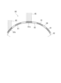
- the solar battery cells 81a arranged substantially horizontally or at an inclination angle
- the arrangement form of the solar battery cells 81 differs depending on the position where the solar battery cells 81 are arranged, such as the solar battery cells 81b which are arranged side by side. The same applies to a solar cell module installed in a portion having a curved surface shape of a structure such as a building.
- the solar cell module 80 installed in a curved shape, even if the sunlight 85 is uniformly irradiated, an appropriate inclination angle with respect to the sunlight 85 cannot be obtained depending on the position where the solar cells 81 are arranged. There will be no Therefore, the amount of solar radiation incident on the solar cells 81 is different, and the current values generated in the solar cells 81 (for example, the solar cells 81a and 81b) are different.
- the current value generated in each solar cell that constitutes the solar cell module for example, the current value generated in one solar cell among a plurality of solar cells connected in series is lower than the others. Therefore, there is a problem that the current value of the solar cell module is rate-determined by the low current value of the one solar cell, resulting in a decrease in the power generation amount.
- the present disclosure has been made in view of the conventional problems described above, and aims to provide a solar cell module that stabilizes the amount of power generated and is suitable for installation on a curved surface, and such a solar cell.
- An object of the present invention is to provide a photovoltaic power generation system having modules.
- the solution of the present disclosure for achieving the above object is a plurality of solar cells spaced apart from each other and arranged along a first direction and a second direction perpendicular to the first direction;
- the premise is a solar cell module having a connection member for electrically connecting the battery cells, and the plurality of solar cells are each flat plate-shaped and sealed with a resin layer having a curved surface shape to form the curved surface.
- One solar cell and the other solar cell adjacent in the first direction are electrically connected in series by the connecting member, and the solar cells adjacent in the second direction are electrically connected in series by the connecting member.
- It is characterized by comprising a solar battery cell group in which one solar battery cell and the other solar battery cell are electrically connected in parallel.
- a plurality of the solar cell groups may be arranged in the second direction, and the adjacent solar cell groups may be electrically connected in parallel.
- the number of the solar cells arranged in the first direction of the solar cell groups is equal to one of the adjacent solar cell groups and the other of the adjacent solar cell groups.
- the photovoltaic cell group may be equally provided.
- the total number of solar cells included in one of the adjacent solar cell groups is equal to the total number of the solar cells included in the other solar cell group. They may be equally configured.
- the total number of solar cells included in one of the adjacent solar cell groups is greater than the total number of the solar cells included in the other solar cell group. It may be configured to have a large number of
- a photovoltaic power generation system including the solar cell modules according to each of the above solutions is also within the scope of the technical ideas of the present disclosure. That is, the photovoltaic power generation system is characterized in that the solar cell module is installed on an installation surface having a curved surface shape.
- one arrangement unit for arranging the plurality of solar cells according to the curved shape of the installation surface is configured, and one solar cell group is provided for each arrangement unit. It is preferable that the plurality of solar cell groups included in the solar cell module are electrically connected in parallel.
- the installation surface may be the surface of a vehicle or the surface of a structure fixed to the ground.
- a connection structure for both the series-connected solar cells and the parallel-connected solar cells is provided. It can be provided, and the current flows avoiding the solar cell whose current value has decreased among the plurality of solar cells, and the problem of being rate-determined by the low current value of the solar cell can be solved.
- the power generation amount of the battery module can be stabilized.
- the solar cell module and the solar power generation system it is possible to suppress the decrease in the current value obtained, and it is possible to stabilize the power generation amount even in the curved installation form.
- FIG. 1 is a plan view schematically showing the configuration of a solar cell module according to Embodiment 1 of the present disclosure.
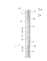
- FIG. 2 is a cross-sectional view showing the internal structure of the solar cell module.
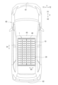
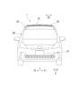
- FIG. 3 is a photovoltaic power generation system according to Embodiment 1 of the present disclosure, which is a plan view showing a vehicle including the photovoltaic module. 4 is a front view of the vehicle shown in FIG. 3.
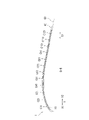
- FIG. FIG. 5A is a cross-sectional view of the solar cell module installed in the vehicle, corresponding to the AA cross-sectional view in FIG. 5B is a cross-sectional view of the solar cell module when installed in the vehicle, and is a cross-sectional view corresponding to the BB in FIG. 1.
- FIG. 6 is a plan view schematically showing the configuration of a solar cell module according to Embodiment 2 of the present disclosure.
- FIG. 7 is a plan view schematically showing the configuration of a solar cell module according to Embodiment 3 of the present disclosure.
- FIG. 8 is a plan view schematically showing the configuration of a solar cell module according to Embodiment 4 of the present disclosure.
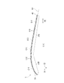
- FIG. 9 is a cross-sectional view of the solar cell module when installed in the vehicle, corresponding to the CC cross-sectional view in FIG.
- FIG. 10 is a perspective view showing a vinyl house provided with the solar cell module.
- FIG. 11 is an explanatory diagram showing the amount of solar radiation in a solar cell module provided on a conventional curved installation surface.
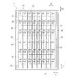
- FIG. 1 is a plan view schematically showing the configuration of a solar cell module 1 according to Embodiment 1 of the present disclosure
- FIG. 2 is a cross-sectional view showing the internal structure of the solar cell module 1 .
- illustration of a resin layer, a protective member, and the like provided in the solar cell module 1 is omitted.
- the solar cell module 1 includes a plurality of solar cells 10 arranged spaced apart from each other, and a plurality of connection members (31, 32).
- the solar cell module 1 has a structure in which the solar cells 10 and the like are sealed between a translucent substrate 41 and a protective member 42 with a translucent resin layer 43 .
- Resin layer 43 is configured to have a curved shape in at least a portion of solar cell module 1 as a whole, and translucent substrate 41 and protective member 42 are arranged along the curved shape of resin layer 43 . ing. Further, as will be described later, each solar battery cell 10 is sealed with a resin layer 43 and arranged along the curved shape of the resin layer 43 .
- the solar cell 10 is a flat photovoltaic element that generates electric power by light irradiation, and includes a front electrode 101 and a back electrode 102 .
- the surface electrodes 101 have busbar electrodes 103 and finger electrodes (not shown).
- the busbar electrodes 103 are strip-shaped, and are linearly formed on the surface of the solar cell 10 in the first direction D1.
- the finger electrodes are formed extending from both side edges of the busbar electrodes 103 in the second direction D2.
- the finger electrodes are patterned to cover the entire light-receiving surface of the solar cell 10 at regular intervals.
- the back surface electrode 102 is formed linearly in the first direction D1 on the back surface of the solar cell 10 in a strip shape, and is provided so as to face the busbar electrode 103 front and back.
- the first connection member 31 is connected to the busbar electrode 103 of the surface electrode 101 of one solar cell 10 and the back surface electrode 102 of the other solar cell 10 to connect the adjacent solar cells 10 in series.
- Translucent substrate 41 is provided so as to face the surface side of solar cell 10 (upper side in FIG. 2).
- Protective member 42 is provided so as to face the back side of solar cell 10 (lower side in FIG. 2).
- the first connection member 31 has a configuration in which the outer surface of a base material formed in an elongated strip shape or a wire with a substantially circular cross section is coated with a conductive adhesive or solder.
- Materials for the base material and wires are not particularly limited, but metals such as copper can be used, for example.
- each of the solar cells 10 (C11 to C124) of the solar cell module 1 is in the form of a flat plate. ing.
- the solar cell 10 divided into two has a size of about 156 mm ⁇ 78 mm square as a whole, and as shown in the figure, two corners of one side in a predetermined direction (for example, the second direction D2) is chamfered (cut).
- the solar cells 10 configured in this manner are arranged in a matrix along a first direction (column direction) D1 and a second direction (row direction) D2.
- the solar cells C11 and C21 arranged adjacent to each other in the first direction D1 are connected in series by the first connection member 31 arranged along the first direction D1.
- the first connection member 31 is arranged in parallel with the surface of the flat solar cell C11, and the lower surface of the first connection member 31 is joined to the surface of the solar cell C11. 31 is bonded to the back surface of the solar cell C21.
- the solar cells C11 and C12 arranged adjacent to each other in the second direction D2 are connected in parallel by the second connection members 32 arranged along the second direction D2.
- the solar cells C13 and C14 adjacent in the second direction D2 are also connected in parallel by the second connection members 32 .
- the second connection member 32 has a configuration in which the outer surface of a base material formed in an elongated strip shape or a wire with a substantially circular cross section is coated with a conductive adhesive or solder.
- Materials for the base material and wires are not particularly limited, but metals such as copper can be used, for example.
- the second connection member 32 may be a metal foil such as a copper foil.
- the second connecting members 32 are connected to the first connecting members 31 or the electrodes of the solar cells 10, and connect the solar cells 10 adjacent to each other in the second direction D2 in parallel.
- the second connection member 32 is arranged on the back surface side of the solar cell 10 and connected to the first connection member 31 connected to the back surface electrode 102 of one solar cell 10 and the back surface of the other solar cell 10 . By being connected to the first connection member 31 connected to the electrode 102, the solar cells 10 adjacent to each other in the second direction D2 are connected in parallel.
- the plurality of solar cells 10 of the solar cell module 1 are electrically connected in series with one solar cell 10 and the other solar cell 10 adjacent in the first direction D1.
- One solar cell 10 and the other solar cell 10 adjacent to D2 are electrically connected in parallel to form a solar cell group 20 .
- the solar cell group 20 of the solar cell module 1 has a connection structure of both the series-connected solar cells 10 and the parallel-connected solar cells 10 .
- An end of the solar cell group 20 is connected to an end electrode wiring 34 via an intermediate connection wiring 33 connected to a second connection member 32 .
- FIG. 3 is an example of a photovoltaic power generation system according to an embodiment of the present disclosure, and is a plan view showing a vehicle 60 including the solar cell module 1, and FIG. 4 is a front view of the vehicle 60 of FIG. .
- 5A and 5B schematically show a cross section of solar cell module 1 when installed in vehicle 60.
- FIG. 5A is a cross section corresponding to AA in FIG. It is a BB sectional equivalent view.
- the solar cell module 1 can be installed, for example, on the roof 63 of a vehicle 60 such as an automobile.
- the longitudinal direction X of the vehicle 60 corresponds to the full length direction of the vehicle 60 from the vehicle front portion (front) 61 to the vehicle rearmost portion (rear) 62, and is the direction along which the vehicle moves forward or backward.
- the width direction Y of the vehicle 60 corresponds to the left-right direction of the vehicle 60 and is a direction orthogonal to the front-rear direction X of the vehicle 60 .
- the roof 63 of the vehicle 60 on which the solar cell module 1 is installed is at least partially curved. Since the panel 40 (resin layer 43 ) of the solar cell module 1 is arranged along the surface of the roof 63 , it has a curved shape similar to that of the roof 63 as a whole.
- the solar cell module 1 is arranged so that the first direction D1 is parallel to the longitudinal direction X of the vehicle 60, and the second direction D2 is the width of the vehicle 60. arranged parallel to the Y direction.
- the plurality of photovoltaic cells 10 of the photovoltaic module 1 are arranged in the front-rear direction X and the width direction Y inside the panel 40 along the curved shape of the roof 63 .
- the plurality of photovoltaic cells 10 of the photovoltaic module 1 are arranged in the second direction D2 corresponding to the width direction Y of the vehicle 60 along a gently curved shape.
- the plurality of photovoltaic cells 10 in a first direction D1 corresponding to the longitudinal direction X of the vehicle 60, have curved surfaces with different curvatures on one end side and the other end side. They are arranged along the shape.
- the solar cells C11 (C12, C13, C14) arranged on the vehicle frontmost portion 61 side (front X1) are arranged, for example, on the vehicle rearmost portion 62 side (rearward X2).
- the solar cells C121 (C122, C123, C124) are arranged with a greater inclination angle.
- the solar cells C41, C51, etc. which are arranged substantially in the middle in the first direction D1, have a smaller inclination angle than the solar cell C11 and are arranged substantially horizontally.
- the light-receiving surfaces of the respective solar cells 10 are arranged facing various directions.
- one of the solar cells 10 (the solar cell C11 or the like located on the end side in the case illustrated in FIG. 5B) has a curvature It is placed on a curved surface with a large
- the photovoltaic cell 10 has a smaller power generation area than other photovoltaic cells 10 arranged on a curved surface portion with a small curvature, and has different electrical characteristics (especially current).
- the solar cell module 1 has a connection structure for both the series-connected solar cells 10 and the parallel-connected solar cells 10, and the solar cells 10 are connected in the second direction D2.
- the solar cells 10 adjacent to each other are connected in parallel. Since the photovoltaic cell 10 with the decreased current value becomes electrical resistance, the current flows through the parallel connection circuit avoiding the photovoltaic cell 10 . Therefore, it is possible to solve the conventional problem that the current value of one solar cell 10 is rate-determined and the current value of the other solar cell 10 decreases. Therefore, it is possible to suppress a decrease in the power generation amount of the solar cell module 1, and it is possible to stabilize the power generation amount even in an installation configuration having a curved surface shape such as the roof 63 of the vehicle 60.
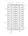
- FIG. 6 is a plan view schematically showing the configuration of the solar cell module 1 according to Embodiment 2 of the present disclosure.
- the arrangement form and connection form of the plurality of solar cells 10 included in the solar cell module 1 are not limited to those shown in the first embodiment, and can be implemented in various forms.
- common reference numerals are used for configurations common to those of Embodiment 1, and overlapping descriptions are omitted.
- the solar cell module 1 has a total of 48 solar cells 10 (C11 to C16, C21 to C26, C31 to C36, 8 ⁇ 6) along the first direction D1 and the second direction D2. , C41 to C46, C51 to C56, C61 to C66, C71 to C76, C81 to C86) are arranged to provide the solar battery cell group 20.
- FIG. The longitudinal direction of the panel 40 of the solar cell module 1 is the second direction D2.
- the solar cells C11 and C21 adjacent in the first direction D1 are connected in series by the first connection member 31 arranged along the first direction D1.
- the solar cells C11 and C12 adjacent in the second direction D2 are connected in parallel by the second connection members 32 arranged along the second direction D2.
- the solar cells C15 and C16 adjacent in the second direction D2 are also connected in parallel by the second connection members 32 .
- Each solar cell 10 is arranged such that one side having two chamfered corners is parallel to the second direction D2.
- one photovoltaic cell 10 adjacent in the first direction D1 and the other photovoltaic cell 10 are electrically connected in series and are adjacent in the second direction D2.
- One solar cell 10 and the other solar cell 10 are electrically connected in parallel to form a solar cell group 20 .
- an intermediate connection wiring 33 is connected to the second connection member 32 between the photovoltaic cells C13 and C14 and between the photovoltaic cells C83 and C84 adjacent in the second direction D2. It is connected to the end electrode wiring 34 via the wiring 33 .
- the solar cell module 1 is installed in such a manner that the first direction D1 corresponds to the width direction Y of the vehicle 60 and the second direction D2 corresponds to the front-rear direction X of the vehicle 60. preferably configured.
- the solar cell module 1 can be installed by making the most of the area of the roof 63 of the vehicle 60, and the parallel connection circuit of the solar cells 10 can be installed in the same manner as the solar cell module 1 according to the first embodiment. Through this, it is possible to avoid a decrease in the current value of the other solar cell 10 due to a lower current value of the one solar cell 10, thereby suppressing a decrease in the amount of power generation.
- FIG. 7 is a plan view schematically showing the configuration of the solar cell module 1 according to Embodiment 3 of the present disclosure.
- the number of photovoltaic cell groups 20 provided in the photovoltaic module 1 is not limited to one, and a plurality of photovoltaic cell groups 20 may be provided.
- the solar cell module 1 includes two solar cell groups 20A and 20B, and these solar cell groups 20A and 20B are arranged adjacent to each other in the second direction D2. .
- a total of 24 solar cells 10 (C11 to C12, C21 to C22, C31 to C32, C41 to C42, C51 ⁇ C52, C61-C62, C71-C72, C81-C82, C91-C92, C101-C102, C111-C112, C121-C122) are arranged.
- the solar cells C11 and C21 adjacent in the first direction D1 are connected in series by the first connection member 31 arranged along the first direction D1. Also, the solar cells C11 and C12 adjacent in the second direction D2 are connected in parallel by the second connection members 32 arranged along the second direction D2.
- a total of 24 solar cells 10 (C13 to C14, C23 to C24, C33 to C34, C43 to C44) are arranged along the first direction D1 and the second direction D2.
- the solar cells C24 and C34 adjacent in the first direction D1 are connected in series by the first connection member 31 arranged along the first direction D1. Also, the solar cells C13 and C14 adjacent in the second direction D2 are connected in parallel by the second connection members 32 arranged along the second direction D2.
- both the photovoltaic cell groups 20A and 20B are electrically separated from one photovoltaic cell 10 and the other photovoltaic cell 10 that are adjacent in the first direction D1.
- one solar cell 10 and the other solar cell 10 adjacent in the second direction D2 are electrically connected in parallel.
- Each solar cell 10 is arranged such that one side having two chamfered corners is parallel to the second direction D2.
- the number of solar cells 10 arranged along the first direction D1 in the two solar cell groups 20A and 20B is Equivalently, 12 solar cells 10 are provided in the first direction D1 in FIG.
- the total number of solar cells 10 included in one of the two adjacent solar cell groups 20A and 20B is equal to the total number of solar cells 10 included in the other solar cell group 20B. It is assumed. Adjacent photovoltaic cell groups 20A and 20B are electrically connected in parallel via intermediate connection wiring 35 .
- the longitudinal direction of the panel 40 is defined as the first direction D1
- the first direction D1 corresponds to the front-rear direction X of the vehicle 60
- the second direction D2 corresponds to the width direction Y of the vehicle 60, so that the photovoltaic power generation system is preferably configured.
- the solar cell module 1 can be installed by making the most of the area of the roof 63 of the vehicle 60, and further, it is possible to suppress the decrease in the amount of power generated due to the decrease in the current value.
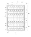
- FIG. 8 is a plan view schematically showing the configuration of a solar cell module 1 according to Embodiment 4 of the present disclosure
- FIG. 9 shows the solar cell module 1 when installed in a vehicle 60 as a photovoltaic power generation system.
- 9 is a cross-sectional view equivalent to CC in FIG. 8, schematically showing the cross section of FIG.
- the photovoltaic cell groups 20 are arranged in accordance with the curved surface shape of the installation surface, and the photovoltaic cell 10 included in each photovoltaic cell group 20 is arranged. may be configured with different total numbers.
- the solar cell module 1 includes two solar cell groups 20C and 20D.
- the longitudinal direction of the panel 40 of the solar cell module 1 is the second direction D2, and the solar cell groups 20C and 20D are arranged adjacent to each other in the second direction D2.
- Each solar cell 10 is arranged such that one side having two chamfered corners is parallel to the second direction D2.
- a total of 32 solar cells 10 (C11 to C14, C21 to C24, C31 to C34, C41-C44, C51-C54, C61-C64, C71-C74, C81-C84) are arranged.
- the solar cells C11 and C21 adjacent in the first direction D1 are connected in series by the first connection member 31 arranged along the first direction D1. Also, the solar cells C11 and C12 adjacent in the second direction D2 are connected in parallel by the second connection members 32 arranged along the second direction D2.
- a total of 16 solar cells 10 (C15-C16, C25-C26, C35-C36, C45-C46 , C55-C56, C65-C66, C75-C76, C85-C86) are arranged.
- the solar cells C75 and C85 adjacent in the first direction D1 are connected in series by the first connection members 31 arranged along the first direction D1. Also, the solar cells C85 and C86 adjacent in the second direction D2 are connected in parallel by the second connection members 32 arranged along the second direction D2.
- one solar cell 10 adjacent in the first direction D1 and the other solar cell 10 of the solar cell module 1 are electrically connected in series, and the one adjacent in the second direction D2 is electrically connected in series.
- One solar cell 10 and the other solar cell 10 are electrically connected in parallel.
- the total number of photovoltaic cells 10 included in one photovoltaic cell group 20C is 32, which is greater than the total number of 16 photovoltaic cells 10 included in the other photovoltaic cell group 20D.
- the number of photovoltaic cells 10 arranged in first direction D1 in photovoltaic cell group 20C is equal to the number of photovoltaic cells 10 arranged in first direction D1 in photovoltaic cell group 20D.
- the longitudinal direction of the panel 40 is defined as the second direction D2 in consideration of the installation form using the roof 63 of the vehicle 60 as the installation surface. It is preferable to adopt an installation form in which D2 corresponds to the longitudinal direction X of the vehicle 60 and the first direction D1 corresponds to the width direction Y of the vehicle 60 .
- the solar cell module 1 is arranged with the second direction D2 corresponding to the front-rear direction X of the vehicle 60 .
- the solar cells C16 (C26, C36, C46, C56, C66, C76, C86) are arranged on the front X1 side of the vehicle 60
- the solar cells C11 (C21, C31, C41, C51 , C61, C71, C81) are arranged on the rear X2 side of the vehicle 60 and installed.
- the roof 63 of the vehicle 60 has curved surface shapes with different curvatures in the front-rear direction X.
- the roof 63 extends in the front-rear direction X, and is inclined upward toward the rear X2 from the vehicle frontmost portion 61 side (front X1) to the middle, and descends toward the vehicle rearmost portion 62 side (rear X2) from the middle. referred to as a slope.
- the front X1 side of the roof 63 which slopes upward, has a curved surface shape with a larger curvature than the rear X2 side of the roof 63, which slopes downward.
- a plurality of photovoltaic cells 10 are arranged in accordance with the curved shape of the surface of the roof 63, which is the installation surface. 20D is preferably provided. That is, as the installation form of the solar cell module 1, the front X1 side and the rear X2 side of the roof 63 having different curvatures correspond to each other, and the front X1 side constitutes one arrangement unit of the solar cells 10, and the rear X2 side constitutes one arrangement unit. It constitutes one arrangement unit of the photovoltaic cell 10 . Then, it is preferable to arrange the solar battery cell groups 20D and 20C for each arrangement unit.
- the solar cell module 1 has a roof 63 with a solar cell group 20D located on the surface of a roof 63 that slopes upward from the front X1 to the rear X2, and the roof 63 slopes downward toward the rear X2. It is installed so that the solar cell group 20C is located on the surface.
- the electrical characteristics of the solar cells 10 (C16, C15) arranged on the front X1 side and the solar cells 10 (C14, C13, C12, C11) arranged on the rear X2 side are different from the difference in the curvature of the installation surface.
- the solar cells 10 (C16, C15) with curved surfaces having a relatively large curvature are provided in the solar cell group 20D
- the solar cells 10 (C14, C15) having relatively small curvatures are provided in the solar cell group 20D.
- C13, C12, C11) are provided in the solar cell group 20C.
- photovoltaic cell group 20D and photovoltaic cell group 20C are electrically connected in parallel via intermediate connection wiring 35 .
- each of the solar cell groups 20D and 20C has a connection structure for both the series-connected solar cells 10 and the parallel-connected solar cells 10, Even within the battery cell groups 20 ⁇ /b>D and 20 ⁇ /b>C, it is possible to avoid a decrease in current value that is rate-determined by a low current value of one of the solar cells 10 .
- the solar cell module 1 can suppress a decrease in the amount of power generated due to a decrease in the current value.
- the solar cell module 1 can be installed by making the most of the area of the roof 63 of the vehicle 60, and the power generation efficiency can be improved by adopting an installation form that matches the curved shape of the installation surface.
- a unit of arrangement of the solar cells 10 is arranged in accordance with the curved surface (according to the portions with different curvatures), and each unit of arrangement is arranged.
- the photovoltaic modules 1 are all connected in series with the photovoltaic cells 10 and in parallel. Since the solar cell module 1 has a connection structure for both of the solar cells 10, the output voltage of the solar cell module 1 can be set within a specified range, and the amount of power generation can be stabilized.
- the solar cell module 1 of the present disclosure can be implemented in various forms other than the first to fourth embodiments.
- a solar power generation system can be constructed by using the surfaces of various structures having curved surfaces other than the roof 63 of the illustrated vehicle 60 as installation surfaces. can be done.
- FIG. 10 is a perspective view showing a vinyl house 70 including the solar cell module 1 as another installation form of the solar power generation system according to this embodiment.
- a vinyl house 70 is fixed to the ground and has a curved roof surface 71 .
- the solar cell module 1 may be installed using the roof surface 71 of the greenhouse 70 having such a curved surface shape as an installation surface.
- the solar cell module 1 installed on the roof surface 71, even if there is a difference in the current value generated by the solar cells, the rate-limiting to a low current value is suppressed, and the amount of power generation can be stabilized.
- the solar cell module 1 can be installed on a surface of a structure having a variety of curved shapes, such as a soundproof wall of a highway or the roof of a carport, to obtain stable power generation.
- the panel 40 of the solar cell module 1 is not limited to the exemplified shape, and may have various shapes. may have a curved surface shape.
- the solar cell 10 provided in the solar cell module 1 may be of a single-sided light-receiving type or a double-sided light-receiving type.
- the type of the solar battery cell 10 is not particularly limited, and those made of various semiconductor materials such as polycrystalline semiconductors and thin film semiconductors can be applied.
- solar cell module 10 solar cell 101 front electrode 102 back electrode 103 bus bar electrode 20 solar cell group 20A, 20B, 20C, 20D solar cell group 31 first connecting member (connecting member) 32 second connection member (connection member) 33 intermediate connection wiring 34 end electrode wiring 35 intermediate connection wiring 40 panel 41 translucent substrate 42 protective member 43 resin layer 60 vehicle 63 roof 70 vinyl house 71 roof surface D1 first direction D2 second direction X front-back direction Y width direction
Landscapes
- Photovoltaic Devices (AREA)
Priority Applications (3)
| Application Number | Priority Date | Filing Date | Title |
|---|---|---|---|
| US18/291,031 US20240332441A1 (en) | 2021-07-26 | 2022-06-29 | Solar cell module and solar power generation system |
| EP22849137.9A EP4379817A4 (en) | 2021-07-26 | 2022-06-29 | SOLAR CELL MODULE AND SOLAR POWER GENERATION SYSTEM |
| CN202280041845.8A CN117501458A (zh) | 2021-07-26 | 2022-06-29 | 太阳能电池模块及太阳能发电系统 |
Applications Claiming Priority (2)
| Application Number | Priority Date | Filing Date | Title |
|---|---|---|---|
| JP2021-121832 | 2021-07-26 | ||
| JP2021121832A JP2023017512A (ja) | 2021-07-26 | 2021-07-26 | 太陽電池モジュールおよび太陽光発電システム |
Publications (1)
| Publication Number | Publication Date |
|---|---|
| WO2023008068A1 true WO2023008068A1 (ja) | 2023-02-02 |
Family
ID=85087938
Family Applications (1)
| Application Number | Title | Priority Date | Filing Date |
|---|---|---|---|
| PCT/JP2022/026073 Ceased WO2023008068A1 (ja) | 2021-07-26 | 2022-06-29 | 太陽電池モジュールおよび太陽光発電システム |
Country Status (5)
| Country | Link |
|---|---|
| US (1) | US20240332441A1 (enExample) |
| EP (1) | EP4379817A4 (enExample) |
| JP (2) | JP2023017512A (enExample) |
| CN (1) | CN117501458A (enExample) |
| WO (1) | WO2023008068A1 (enExample) |
Citations (10)
| Publication number | Priority date | Publication date | Assignee | Title |
|---|---|---|---|---|
| JPH0953211A (ja) * | 1995-08-10 | 1997-02-25 | Kensetsusho Kanto Chiho Kensetsu Kyokucho | 遮音壁を利用した太陽光エネルギー活用発電装置 |
| JPH10306517A (ja) * | 1997-05-07 | 1998-11-17 | Sekisui Chem Co Ltd | 太陽電池付きの曲面屋根パネル及び該屋根パネルを用いたボールト屋根 |
| JP2010021499A (ja) * | 2008-07-14 | 2010-01-28 | Mitsubishi Chemicals Corp | 車両用太陽電池パネル、太陽電池付き車両及び太陽電池シート |
| US20110290306A1 (en) * | 2010-04-26 | 2011-12-01 | Todd Roberts | Solar array configurations |
| JP2012033573A (ja) | 2010-07-28 | 2012-02-16 | Mazda Motor Corp | 車載太陽電池パネル及びその取付構造 |
| JP2016178120A (ja) * | 2015-03-18 | 2016-10-06 | トヨタ自動車株式会社 | 太陽電池モジュール |
| JP2019533408A (ja) * | 2017-05-12 | 2019-11-14 | フレックス,リミテッド | 車両用ソーラールーフ用板葺式アレイモジュール |
| JP2020505774A (ja) * | 2017-01-31 | 2020-02-20 | ソーラーワット リミテッド | マトリクス接続された太陽電池サブセルを有する太陽光モジュール |
| US20200144432A1 (en) * | 2017-04-24 | 2020-05-07 | Lg Electronics Inc. | Curved solar cell module |
| JP2021121832A (ja) | 2020-01-31 | 2021-08-26 | マクセル株式会社 | 車両用情報表示システム及び情報表示システム |
Family Cites Families (5)
| Publication number | Priority date | Publication date | Assignee | Title |
|---|---|---|---|---|
| US20160087132A1 (en) * | 2014-09-19 | 2016-03-24 | Hamad Musabeh Ahmed Saif Alteneiji | Dynamic PV Module And Method Of Manufacturing |
| JP2019140302A (ja) * | 2018-02-14 | 2019-08-22 | パナソニック株式会社 | 太陽電池モジュール |
| CN110391309A (zh) * | 2018-04-12 | 2019-10-29 | 北京汉能光伏投资有限公司 | 一种太阳能电池模组、制备方法及车辆 |
| JP2020167282A (ja) * | 2019-03-29 | 2020-10-08 | パナソニック株式会社 | 太陽電池モジュール |
| JP2020167280A (ja) * | 2019-03-29 | 2020-10-08 | パナソニック株式会社 | 太陽電池モジュール |
-
2021
- 2021-07-26 JP JP2021121832A patent/JP2023017512A/ja active Pending
-
2022
- 2022-06-29 WO PCT/JP2022/026073 patent/WO2023008068A1/ja not_active Ceased
- 2022-06-29 US US18/291,031 patent/US20240332441A1/en active Pending
- 2022-06-29 CN CN202280041845.8A patent/CN117501458A/zh active Pending
- 2022-06-29 EP EP22849137.9A patent/EP4379817A4/en active Pending
-
2023
- 2023-12-28 JP JP2023222740A patent/JP2024028355A/ja active Pending
Patent Citations (10)
| Publication number | Priority date | Publication date | Assignee | Title |
|---|---|---|---|---|
| JPH0953211A (ja) * | 1995-08-10 | 1997-02-25 | Kensetsusho Kanto Chiho Kensetsu Kyokucho | 遮音壁を利用した太陽光エネルギー活用発電装置 |
| JPH10306517A (ja) * | 1997-05-07 | 1998-11-17 | Sekisui Chem Co Ltd | 太陽電池付きの曲面屋根パネル及び該屋根パネルを用いたボールト屋根 |
| JP2010021499A (ja) * | 2008-07-14 | 2010-01-28 | Mitsubishi Chemicals Corp | 車両用太陽電池パネル、太陽電池付き車両及び太陽電池シート |
| US20110290306A1 (en) * | 2010-04-26 | 2011-12-01 | Todd Roberts | Solar array configurations |
| JP2012033573A (ja) | 2010-07-28 | 2012-02-16 | Mazda Motor Corp | 車載太陽電池パネル及びその取付構造 |
| JP2016178120A (ja) * | 2015-03-18 | 2016-10-06 | トヨタ自動車株式会社 | 太陽電池モジュール |
| JP2020505774A (ja) * | 2017-01-31 | 2020-02-20 | ソーラーワット リミテッド | マトリクス接続された太陽電池サブセルを有する太陽光モジュール |
| US20200144432A1 (en) * | 2017-04-24 | 2020-05-07 | Lg Electronics Inc. | Curved solar cell module |
| JP2019533408A (ja) * | 2017-05-12 | 2019-11-14 | フレックス,リミテッド | 車両用ソーラールーフ用板葺式アレイモジュール |
| JP2021121832A (ja) | 2020-01-31 | 2021-08-26 | マクセル株式会社 | 車両用情報表示システム及び情報表示システム |
Non-Patent Citations (1)
| Title |
|---|
| See also references of EP4379817A4 |
Also Published As
| Publication number | Publication date |
|---|---|
| EP4379817A4 (en) | 2025-07-16 |
| EP4379817A1 (en) | 2024-06-05 |
| JP2023017512A (ja) | 2023-02-07 |
| CN117501458A (zh) | 2024-02-02 |
| US20240332441A1 (en) | 2024-10-03 |
| JP2024028355A (ja) | 2024-03-04 |
Similar Documents
| Publication | Publication Date | Title |
|---|---|---|
| US9948232B2 (en) | Method for fabricating flexible solar panel module | |
| JP5687506B2 (ja) | 太陽電池及び太陽電池モジュール | |
| JP3679611B2 (ja) | 太陽電池モジュール | |
| JP5874011B2 (ja) | 太陽電池及び太陽電池モジュール | |
| JP3674234B2 (ja) | 大型太陽電池モジュール | |
| AU2023208147B2 (en) | Photovoltaic module and manufacturing method for photovoltaic module | |
| WO2012057243A1 (ja) | 太陽電池及び太陽電池モジュール | |
| US20250344519A1 (en) | Curved photovoltaic module and photovoltaic building surface | |
| CN119855299B (zh) | 太阳能电池、电池组件以及光伏系统 | |
| WO2023008068A1 (ja) | 太陽電池モジュールおよび太陽光発電システム | |
| JP2567294Y2 (ja) | 太陽電池モジュール | |
| JP2020167282A (ja) | 太陽電池モジュール | |
| JP4772011B2 (ja) | 太陽電池モジュール | |
| JP2020167280A (ja) | 太陽電池モジュール | |
| US20250324773A1 (en) | Curved photovoltaic module and photovoltaic building surface | |
| JP3347620B2 (ja) | 太陽電池 | |
| EP4669060A1 (en) | Curved photovoltaic component and photovoltaic building surface | |
| US20250158561A1 (en) | Curved photovoltaic member and photovoltaic building surface | |
| JP2003069064A (ja) | 太陽電池モジュールとその製造方法 | |
| KR102679616B1 (ko) | 투광성이 우수한 태양광 모듈용 태양전지 스트립 및 이의 제조방법 | |
| JP5367090B2 (ja) | 太陽電池モジュール及びその製造方法 | |
| JP5906422B2 (ja) | 太陽電池及び太陽電池モジュール | |
| KR20240057178A (ko) | 투광성이 우수한 태양광 윈도우 시스템 및 이의 제조 방법 | |
| JPH0555618A (ja) | 太陽電池発電装置 | |
| JP2001111087A (ja) | 太陽電池モジュール |
Legal Events
| Date | Code | Title | Description |
|---|---|---|---|
| 121 | Ep: the epo has been informed by wipo that ep was designated in this application |
Ref document number: 22849137 Country of ref document: EP Kind code of ref document: A1 |
|
| WWE | Wipo information: entry into national phase |
Ref document number: 202280041845.8 Country of ref document: CN |
|
| WWE | Wipo information: entry into national phase |
Ref document number: 18291031 Country of ref document: US |
|
| WWE | Wipo information: entry into national phase |
Ref document number: 202447011691 Country of ref document: IN |
|
| WWE | Wipo information: entry into national phase |
Ref document number: 2022849137 Country of ref document: EP |
|
| NENP | Non-entry into the national phase |
Ref country code: DE |
|
| ENP | Entry into the national phase |
Ref document number: 2022849137 Country of ref document: EP Effective date: 20240226 |