WO2023001678A1 - Installation de stockage pour gaz liquéfié - Google Patents
Installation de stockage pour gaz liquéfié Download PDFInfo
- Publication number
- WO2023001678A1 WO2023001678A1 PCT/EP2022/069695 EP2022069695W WO2023001678A1 WO 2023001678 A1 WO2023001678 A1 WO 2023001678A1 EP 2022069695 W EP2022069695 W EP 2022069695W WO 2023001678 A1 WO2023001678 A1 WO 2023001678A1
- Authority
- WO
- WIPO (PCT)
- Prior art keywords
- primary
- insulating
- storage installation
- fixed
- loading
- Prior art date
Links
- 238000003860 storage Methods 0.000 title claims abstract description 50
- 238000009434 installation Methods 0.000 title claims abstract description 38
- 238000004873 anchoring Methods 0.000 claims abstract description 51
- 230000004888 barrier function Effects 0.000 claims abstract description 42
- 239000012528 membrane Substances 0.000 claims description 76
- 238000007789 sealing Methods 0.000 claims description 72
- 229910052751 metal Inorganic materials 0.000 claims description 26
- 239000002184 metal Substances 0.000 claims description 26
- 238000007667 floating Methods 0.000 claims description 23
- 238000009413 insulation Methods 0.000 claims description 21
- 239000006260 foam Substances 0.000 claims description 13
- 230000000284 resting effect Effects 0.000 claims description 10
- 239000012263 liquid product Substances 0.000 claims description 8
- 125000006850 spacer group Chemical group 0.000 claims description 5
- 238000012546 transfer Methods 0.000 claims description 5
- 238000000034 method Methods 0.000 claims description 2
- 239000003949 liquefied natural gas Substances 0.000 description 16
- 238000004078 waterproofing Methods 0.000 description 13
- 239000007789 gas Substances 0.000 description 11
- 230000008602 contraction Effects 0.000 description 10
- PXHVJJICTQNCMI-UHFFFAOYSA-N Nickel Chemical compound [Ni] PXHVJJICTQNCMI-UHFFFAOYSA-N 0.000 description 6
- 239000011120 plywood Substances 0.000 description 6
- 229910000640 Fe alloy Inorganic materials 0.000 description 5
- 239000010935 stainless steel Substances 0.000 description 5
- 229910001220 stainless steel Inorganic materials 0.000 description 5
- 238000003466 welding Methods 0.000 description 5
- 239000011491 glass wool Substances 0.000 description 4
- 229910001374 Invar Inorganic materials 0.000 description 3
- 239000002131 composite material Substances 0.000 description 3
- 239000011152 fibreglass Substances 0.000 description 3
- 239000010451 perlite Substances 0.000 description 3
- 235000019362 perlite Nutrition 0.000 description 3
- 229920000642 polymer Polymers 0.000 description 3
- PWHULOQIROXLJO-UHFFFAOYSA-N Manganese Chemical compound [Mn] PWHULOQIROXLJO-UHFFFAOYSA-N 0.000 description 2
- 229910000990 Ni alloy Inorganic materials 0.000 description 2
- 239000000969 carrier Substances 0.000 description 2
- 239000000835 fiber Substances 0.000 description 2
- 239000003365 glass fiber Substances 0.000 description 2
- 239000003915 liquefied petroleum gas Substances 0.000 description 2
- 239000011572 manganese Substances 0.000 description 2
- 238000012856 packing Methods 0.000 description 2
- 230000000717 retained effect Effects 0.000 description 2
- 239000007921 spray Substances 0.000 description 2
- 229910000975 Carbon steel Inorganic materials 0.000 description 1
- 229910000617 Mangalloy Inorganic materials 0.000 description 1
- 229910000914 Mn alloy Inorganic materials 0.000 description 1
- 229920005830 Polyurethane Foam Polymers 0.000 description 1
- 239000004965 Silica aerogel Substances 0.000 description 1
- 229910000831 Steel Inorganic materials 0.000 description 1
- 229910000746 Structural steel Inorganic materials 0.000 description 1
- 238000004026 adhesive bonding Methods 0.000 description 1
- 238000005452 bending Methods 0.000 description 1
- 239000010962 carbon steel Substances 0.000 description 1
- 230000015556 catabolic process Effects 0.000 description 1
- 238000006731 degradation reaction Methods 0.000 description 1
- 238000013461 design Methods 0.000 description 1
- 238000005516 engineering process Methods 0.000 description 1
- 239000000446 fuel Substances 0.000 description 1
- 239000002828 fuel tank Substances 0.000 description 1
- -1 fumed silicas Substances 0.000 description 1
- 230000005484 gravity Effects 0.000 description 1
- 239000012212 insulator Substances 0.000 description 1
- 239000007788 liquid Substances 0.000 description 1
- 238000004519 manufacturing process Methods 0.000 description 1
- 239000000463 material Substances 0.000 description 1
- 239000011490 mineral wool Substances 0.000 description 1
- 229910052759 nickel Inorganic materials 0.000 description 1
- 229920002635 polyurethane Polymers 0.000 description 1
- 239000004814 polyurethane Substances 0.000 description 1
- 239000011496 polyurethane foam Substances 0.000 description 1
- 238000003825 pressing Methods 0.000 description 1
- 238000005086 pumping Methods 0.000 description 1
- 239000011347 resin Substances 0.000 description 1
- 229920005989 resin Polymers 0.000 description 1
- 239000011435 rock Substances 0.000 description 1
- 238000000926 separation method Methods 0.000 description 1
- 239000010959 steel Substances 0.000 description 1
- 230000007704 transition Effects 0.000 description 1
- 238000013519 translation Methods 0.000 description 1
- XLYOFNOQVPJJNP-UHFFFAOYSA-N water Substances O XLYOFNOQVPJJNP-UHFFFAOYSA-N 0.000 description 1
Images


Classifications
-
- B—PERFORMING OPERATIONS; TRANSPORTING
- B63—SHIPS OR OTHER WATERBORNE VESSELS; RELATED EQUIPMENT
- B63B—SHIPS OR OTHER WATERBORNE VESSELS; EQUIPMENT FOR SHIPPING
- B63B25/00—Load-accommodating arrangements, e.g. stowing, trimming; Vessels characterised thereby
- B63B25/02—Load-accommodating arrangements, e.g. stowing, trimming; Vessels characterised thereby for bulk goods
- B63B25/08—Load-accommodating arrangements, e.g. stowing, trimming; Vessels characterised thereby for bulk goods fluid
- B63B25/12—Load-accommodating arrangements, e.g. stowing, trimming; Vessels characterised thereby for bulk goods fluid closed
- B63B25/16—Load-accommodating arrangements, e.g. stowing, trimming; Vessels characterised thereby for bulk goods fluid closed heat-insulated
-
- F—MECHANICAL ENGINEERING; LIGHTING; HEATING; WEAPONS; BLASTING
- F17—STORING OR DISTRIBUTING GASES OR LIQUIDS
- F17C—VESSELS FOR CONTAINING OR STORING COMPRESSED, LIQUEFIED OR SOLIDIFIED GASES; FIXED-CAPACITY GAS-HOLDERS; FILLING VESSELS WITH, OR DISCHARGING FROM VESSELS, COMPRESSED, LIQUEFIED, OR SOLIDIFIED GASES
- F17C3/00—Vessels not under pressure
- F17C3/02—Vessels not under pressure with provision for thermal insulation
- F17C3/025—Bulk storage in barges or on ships
- F17C3/027—Wallpanels for so-called membrane tanks
-
- B—PERFORMING OPERATIONS; TRANSPORTING
- B63—SHIPS OR OTHER WATERBORNE VESSELS; RELATED EQUIPMENT
- B63B—SHIPS OR OTHER WATERBORNE VESSELS; EQUIPMENT FOR SHIPPING
- B63B27/00—Arrangement of ship-based loading or unloading equipment for cargo or passengers
- B63B27/24—Arrangement of ship-based loading or unloading equipment for cargo or passengers of pipe-lines
-
- B—PERFORMING OPERATIONS; TRANSPORTING
- B63—SHIPS OR OTHER WATERBORNE VESSELS; RELATED EQUIPMENT
- B63B—SHIPS OR OTHER WATERBORNE VESSELS; EQUIPMENT FOR SHIPPING
- B63B27/00—Arrangement of ship-based loading or unloading equipment for cargo or passengers
- B63B27/30—Arrangement of ship-based loading or unloading equipment for transfer at sea between ships or between ships and off-shore structures
- B63B27/34—Arrangement of ship-based loading or unloading equipment for transfer at sea between ships or between ships and off-shore structures using pipe-lines
-
- B—PERFORMING OPERATIONS; TRANSPORTING
- B63—SHIPS OR OTHER WATERBORNE VESSELS; RELATED EQUIPMENT
- B63B—SHIPS OR OTHER WATERBORNE VESSELS; EQUIPMENT FOR SHIPPING
- B63B73/00—Building or assembling vessels or marine structures, e.g. hulls or offshore platforms
- B63B73/20—Building or assembling prefabricated vessel modules or parts other than hull blocks, e.g. engine rooms, rudders, propellers, superstructures, berths, holds or tanks
-
- B—PERFORMING OPERATIONS; TRANSPORTING
- B63—SHIPS OR OTHER WATERBORNE VESSELS; RELATED EQUIPMENT
- B63B—SHIPS OR OTHER WATERBORNE VESSELS; EQUIPMENT FOR SHIPPING
- B63B73/00—Building or assembling vessels or marine structures, e.g. hulls or offshore platforms
- B63B73/40—Building or assembling vessels or marine structures, e.g. hulls or offshore platforms characterised by joining methods
- B63B73/49—Building or assembling vessels or marine structures, e.g. hulls or offshore platforms characterised by joining methods by means of threaded members, e.g. screws, threaded bolts or nuts
-
- F—MECHANICAL ENGINEERING; LIGHTING; HEATING; WEAPONS; BLASTING
- F17—STORING OR DISTRIBUTING GASES OR LIQUIDS
- F17C—VESSELS FOR CONTAINING OR STORING COMPRESSED, LIQUEFIED OR SOLIDIFIED GASES; FIXED-CAPACITY GAS-HOLDERS; FILLING VESSELS WITH, OR DISCHARGING FROM VESSELS, COMPRESSED, LIQUEFIED, OR SOLIDIFIED GASES
- F17C13/00—Details of vessels or of the filling or discharging of vessels
- F17C13/004—Details of vessels or of the filling or discharging of vessels for large storage vessels not under pressure
-
- F—MECHANICAL ENGINEERING; LIGHTING; HEATING; WEAPONS; BLASTING
- F17—STORING OR DISTRIBUTING GASES OR LIQUIDS
- F17C—VESSELS FOR CONTAINING OR STORING COMPRESSED, LIQUEFIED OR SOLIDIFIED GASES; FIXED-CAPACITY GAS-HOLDERS; FILLING VESSELS WITH, OR DISCHARGING FROM VESSELS, COMPRESSED, LIQUEFIED, OR SOLIDIFIED GASES
- F17C2201/00—Vessel construction, in particular geometry, arrangement or size
- F17C2201/01—Shape
- F17C2201/0147—Shape complex
- F17C2201/0157—Polygonal
-
- F—MECHANICAL ENGINEERING; LIGHTING; HEATING; WEAPONS; BLASTING
- F17—STORING OR DISTRIBUTING GASES OR LIQUIDS
- F17C—VESSELS FOR CONTAINING OR STORING COMPRESSED, LIQUEFIED OR SOLIDIFIED GASES; FIXED-CAPACITY GAS-HOLDERS; FILLING VESSELS WITH, OR DISCHARGING FROM VESSELS, COMPRESSED, LIQUEFIED, OR SOLIDIFIED GASES
- F17C2201/00—Vessel construction, in particular geometry, arrangement or size
- F17C2201/05—Size
- F17C2201/052—Size large (>1000 m3)
-
- F—MECHANICAL ENGINEERING; LIGHTING; HEATING; WEAPONS; BLASTING
- F17—STORING OR DISTRIBUTING GASES OR LIQUIDS
- F17C—VESSELS FOR CONTAINING OR STORING COMPRESSED, LIQUEFIED OR SOLIDIFIED GASES; FIXED-CAPACITY GAS-HOLDERS; FILLING VESSELS WITH, OR DISCHARGING FROM VESSELS, COMPRESSED, LIQUEFIED, OR SOLIDIFIED GASES
- F17C2203/00—Vessel construction, in particular walls or details thereof
- F17C2203/03—Thermal insulations
- F17C2203/0304—Thermal insulations by solid means
- F17C2203/0358—Thermal insulations by solid means in form of panels
-
- F—MECHANICAL ENGINEERING; LIGHTING; HEATING; WEAPONS; BLASTING
- F17—STORING OR DISTRIBUTING GASES OR LIQUIDS
- F17C—VESSELS FOR CONTAINING OR STORING COMPRESSED, LIQUEFIED OR SOLIDIFIED GASES; FIXED-CAPACITY GAS-HOLDERS; FILLING VESSELS WITH, OR DISCHARGING FROM VESSELS, COMPRESSED, LIQUEFIED, OR SOLIDIFIED GASES
- F17C2209/00—Vessel construction, in particular methods of manufacturing
- F17C2209/23—Manufacturing of particular parts or at special locations
- F17C2209/234—Manufacturing of particular parts or at special locations of closing end pieces, e.g. caps
-
- F—MECHANICAL ENGINEERING; LIGHTING; HEATING; WEAPONS; BLASTING
- F17—STORING OR DISTRIBUTING GASES OR LIQUIDS
- F17C—VESSELS FOR CONTAINING OR STORING COMPRESSED, LIQUEFIED OR SOLIDIFIED GASES; FIXED-CAPACITY GAS-HOLDERS; FILLING VESSELS WITH, OR DISCHARGING FROM VESSELS, COMPRESSED, LIQUEFIED, OR SOLIDIFIED GASES
- F17C2221/00—Handled fluid, in particular type of fluid
- F17C2221/03—Mixtures
- F17C2221/032—Hydrocarbons
- F17C2221/033—Methane, e.g. natural gas, CNG, LNG, GNL, GNC, PLNG
-
- F—MECHANICAL ENGINEERING; LIGHTING; HEATING; WEAPONS; BLASTING
- F17—STORING OR DISTRIBUTING GASES OR LIQUIDS
- F17C—VESSELS FOR CONTAINING OR STORING COMPRESSED, LIQUEFIED OR SOLIDIFIED GASES; FIXED-CAPACITY GAS-HOLDERS; FILLING VESSELS WITH, OR DISCHARGING FROM VESSELS, COMPRESSED, LIQUEFIED, OR SOLIDIFIED GASES
- F17C2223/00—Handled fluid before transfer, i.e. state of fluid when stored in the vessel or before transfer from the vessel
- F17C2223/01—Handled fluid before transfer, i.e. state of fluid when stored in the vessel or before transfer from the vessel characterised by the phase
- F17C2223/0146—Two-phase
- F17C2223/0153—Liquefied gas, e.g. LPG, GPL
- F17C2223/0161—Liquefied gas, e.g. LPG, GPL cryogenic, e.g. LNG, GNL, PLNG
-
- F—MECHANICAL ENGINEERING; LIGHTING; HEATING; WEAPONS; BLASTING
- F17—STORING OR DISTRIBUTING GASES OR LIQUIDS
- F17C—VESSELS FOR CONTAINING OR STORING COMPRESSED, LIQUEFIED OR SOLIDIFIED GASES; FIXED-CAPACITY GAS-HOLDERS; FILLING VESSELS WITH, OR DISCHARGING FROM VESSELS, COMPRESSED, LIQUEFIED, OR SOLIDIFIED GASES
- F17C2223/00—Handled fluid before transfer, i.e. state of fluid when stored in the vessel or before transfer from the vessel
- F17C2223/03—Handled fluid before transfer, i.e. state of fluid when stored in the vessel or before transfer from the vessel characterised by the pressure level
- F17C2223/033—Small pressure, e.g. for liquefied gas
-
- F—MECHANICAL ENGINEERING; LIGHTING; HEATING; WEAPONS; BLASTING
- F17—STORING OR DISTRIBUTING GASES OR LIQUIDS
- F17C—VESSELS FOR CONTAINING OR STORING COMPRESSED, LIQUEFIED OR SOLIDIFIED GASES; FIXED-CAPACITY GAS-HOLDERS; FILLING VESSELS WITH, OR DISCHARGING FROM VESSELS, COMPRESSED, LIQUEFIED, OR SOLIDIFIED GASES
- F17C2260/00—Purposes of gas storage and gas handling
- F17C2260/01—Improving mechanical properties or manufacturing
- F17C2260/013—Reducing manufacturing time or effort
-
- F—MECHANICAL ENGINEERING; LIGHTING; HEATING; WEAPONS; BLASTING
- F17—STORING OR DISTRIBUTING GASES OR LIQUIDS
- F17C—VESSELS FOR CONTAINING OR STORING COMPRESSED, LIQUEFIED OR SOLIDIFIED GASES; FIXED-CAPACITY GAS-HOLDERS; FILLING VESSELS WITH, OR DISCHARGING FROM VESSELS, COMPRESSED, LIQUEFIED, OR SOLIDIFIED GASES
- F17C2270/00—Applications
- F17C2270/01—Applications for fluid transport or storage
- F17C2270/0102—Applications for fluid transport or storage on or in the water
- F17C2270/0105—Ships
- F17C2270/0107—Wall panels
Definitions
- the invention relates to the field of storage facilities for liquefied gas comprising a sealed and thermally insulating tank, with a sealed membrane.
- the invention relates to the field of sealed and thermally insulating tanks for the storage and/or transport of liquefied gas at low temperature, such as tanks for the transport of Liquefied Petroleum Gas (also called LPG) having for example a temperature between -50°C and 0°C, or for the transport of Liquefied Natural Gas (LNG) at around -162°C at atmospheric pressure.
- LPG Liquefied Petroleum Gas
- LNG Liquefied Natural Gas
- a secondary thermally insulating barrier integrated into the load-bearing structure of a ship, comprising a secondary thermally insulating barrier, a secondary sealing membrane, a primary thermally insulating barrier and a primary waterproofing membrane.
- the vessel has a plurality of vessel walls joined together.
- the secondary waterproofing membrane comprises a plurality of parallel strakes. Each strake has a flat central portion extending in a first direction and two raised edges arranged on either side of the flat central portion and projecting towards the inside of the tank with respect to the central portion. The strakes are thus juxtaposed in a pattern repeated in a second direction and welded together at the raised edges.
- Such a secondary waterproofing membrane commonly referred to as a stretched membrane, does not have zones in the first direction to absorb tensile and compressive forces, unlike a corrugated membrane.
- the secondary waterproofing membrane is interrupted at an opening in order, for example, to allow the crossing of loading/unloading pipes.
- the secondary waterproofing membrane is stopped and is directly connected to the load-bearing structure in order in particular to take up the tensile and compressive forces resulting from the thermal contraction of the waterproofing membranes, the deformation of the hull linked for example to the deflection of the ship's beam, and the state of filling of the tanks.
- Document KR20200144178 describes a vessel wall at the level of such an interruption formed by a liquid dome.
- One idea underlying the invention is to design a support for the primary waterproofing membrane near an opening.
- Another idea underlying the invention is to simply mount the primary thermally insulating barrier.
- the invention provides a storage facility for liquefied gas comprising a metal support structure and a sealed and thermally insulating tank arranged in the support structure, the tank comprising in a direction of thickness from the outside towards the inside of the tank, a secondary thermally insulating barrier fixed to the supporting structure, a secondary metal sealing membrane placed on the secondary thermally insulating barrier, a thermally primary insulating membrane placed on the secondary sealing membrane, and a primary sealing membrane placed on the primary thermally insulating barrier and intended to be in contact with the liquefied gas, the load-bearing structure comprising an upper load-bearing wall, the tank comprising a ceiling wall fixed to the upper load-bearing wall, the ceiling wall being interrupted locally so as to delimit a loading/unloading opening intended to be crossed by loading/unloading pipes, wherein the secondary thermally insulating barrier of the ceiling wall comprises a secondary end insulating block adjacent to an edge of the loading/unloading opening, said edge extending in a second direction,
- the support of the primary waterproofing membrane is achieved by limiting the appearance of steps due to the differences in thermal contraction in the direction of thickness between the different portions of the ceiling wall.
- the secondary fixing support is here surmounted by both the primary end insulating block and the primary insulating panel which have different rigidities so as to form a transition zone between the portion of the ceiling wall comprising only insulating panels and the portion of the ceiling wall formed by the secondary fixing support surmounted by the primary end insulating block.
- the anchoring of the primary insulation panel is facilitated because it is anchored directly on the secondary cap.
- such a storage facility may comprise one or more of the following characteristics.
- the secondary thermally insulating barrier comprises a secondary stop plate arranged on the secondary end insulating block, an end portion of the secondary sealing membrane being fixed to the secondary stop plate.
- the secondary sealing membrane of the ceiling wall comprises a plurality of parallel strakes extending in the first direction, each strake comprising a planar central portion and two raised edges projecting inwards from the tank relative to the central portion, the strakes being juxtaposed in the second direction in a repeated pattern and welded together in a sealed manner at the raised edges, at least one of said strakes being interrupted by the loading/unloading opening.
- an end portion of said interrupted strake is fixed to the secondary stop plate.
- the primary end insulating block is made in the form of a box comprising a bottom plate, a cover plate parallel to the bottom plate and supporting spacer plates holding the cover plate at a distance from the bottom plate, the box being filled with insulating packing, for example perlite, fumed silicas, silica aerogels or glass wool.
- insulating packing for example perlite, fumed silicas, silica aerogels or glass wool.
- the primary insulating panel comprises successively along the direction of thickness at least one layer of insulating foam and at least one rigid plate.
- the primary insulation panel has a layer of foam insulation sandwiched between a bottom plate and a cover plate.
- the insulating foam is a polymer foam, for example a polyurethane foam. According to one embodiment, this insulating foam has a density greater than 100 kg/m 3 , preferably greater than or equal to 120 kg/m 3 , in particular equal to 130 or 150 or 210 kg/m 3 .
- the structural insulating foam is a reinforced foam, for example reinforced with fibers such as glass fibers.
- the bottom panel is a panel of plywood or composite with fiberglass.
- the cover panel is a panel of plywood or composite with fiberglass.
- the coefficient of thermal contraction of the primary insulating end block in said direction of thickness is less than the coefficient of thermal contraction in said direction of thickness of the primary insulating panel.
- the primary end insulating block is of parallelepipedal shape and comprises two side faces perpendicular to the second direction, at least one of the side faces being fixed using the first anchoring device to the secondary cap of the secondary mounting bracket.
- a dimension of the primary end insulating block in the second direction is equal to a distance between two adjacent secondary fixing supports, and the two lateral faces of the primary end insulating block are fixed respectively to the secondary caps of the two secondary mounting brackets using two first anchoring devices.
- the primary end insulating block comprises a bearing surface and the first anchoring device comprises a base fixed to the secondary cap, a stud fixed to said base and developing along the direction of thickness and passing through in leaktight manner an orifice of the secondary sealing membrane, and a support element mounted on the stud and resting on the support surface of the primary end insulating block so as to retain it on the secondary fixing support .
- At least one of the side faces of the primary end insulating block comprises a protuberance, the bearing surface being formed on the protuberance.
- the primary insulating panel comprises a bearing surface and the second anchoring device comprises a base fixed to the secondary cap, a stud fixed to said base and developing in the direction of thickness and crossing so seals an orifice of the secondary sealing membrane, and a support element mounted on the stud and resting on the support surface of the primary insulating panel so as to retain it to the secondary fixing support.
- the bearing surface of the primary insulating panel is located at a corner or at a distance from a corner of the primary insulating panel.
- the first anchoring device and/or the second anchoring device further comprise a flange forming an integral part of the stud, the flange projecting radially towards the outside of the stud and being fixed in leaktight manner to the secondary waterproofing membrane around the opening of the secondary waterproofing membrane.
- the first anchoring device and/or the second anchoring device further comprise a collar which is engaged on the stud and which is fixed in leaktight manner to the secondary waterproofing membrane around the orifice of the secondary sealing membrane and a deformable gasket sealingly connecting the collar to the stud so as to allow relative movement between the collar and the stud.
- an interface between the end secondary insulating block and the secondary insulating panel is located at a greater distance from the edge of the loading/unloading opening in the first direction than an interface between the insulating block end primary and the primary insulation panel.
- the first anchor device and the second anchor device are formed identically, the first anchor device and the second anchor device being spaced apart from each other in the first direction.
- the storage facility comprises a connecting angle extending in the second direction to separate the secondary thermally insulating barrier from the loading/unloading opening in leaktight manner, the connecting angle comprising a first wing and a second wing connected to the first wing, the first wing being fixed to the secondary stop plate and the second wing being welded to an anchor plate integral with the upper load-bearing wall.
- the secondary foot is spaced from the anchor plate in the first direction, preferably by a distance greater than or equal to 15 mm, more preferably greater than or equal to 20 mm.
- the secondary thermally insulating barrier comprises the secondary end insulating block and secondary insulating panels, the secondary insulating panel adjacent to the secondary end insulating block in the first direction comprising a structure different from the other secondary insulating panels , for example so as to be of greater rigidity in the direction of thickness than the other secondary insulating panels or to have a lower coefficient of thermal contraction.
- a metallic secondary fixing plate is fixed on an upper surface of the secondary stop plate, and an end portion of the or each strake interrupted by the loading/unloading opening is welded to the secondary metal fixing plate.
- a secondary metal fixing plate is made of an iron alloy with nickel, for example Invar, an iron alloy with manganese or stainless steel.
- the deformable seal comprises a deformable bellows, said deformable bellows being hollow and developing around and axially along the stud.
- the deformable bellows is for example made of stainless steel.
- the first anchoring device and/or the second anchoring device comprises a bell covering the deformable bellows, the bell having a cylindrical shape.
- the base of the first anchoring device and/or of the second anchoring device is fixed by screwing or welding to the secondary cap of the secondary fixing support.
- the seating length of the secondary support portion in the first direction is greater than or equal to 300mm.
- the primary waterproofing membrane can be made in various ways.
- the primary sealing membrane of the ceiling wall comprises a plurality of corrugated metal plates juxtaposed in the first direction and the second direction, and welded to each other, the primary sealing membrane comprising a first series of undulations extending in the first direction and a second series of undulations extending in the second direction.
- the spacing between two adjacent secondary fixing supports in the second direction is equal to an integer multiple of the dimension of a strake in the second direction, for example equal to the dimension of a strake in the second direction.
- the dimension of a strake in the second direction is equal to 510mm.
- the end portion of the or each strake welded to the secondary metal fixing plate has a thickness greater than the thickness of the strake at a distance from the loading/unloading opening.
- the thickness is a dimension measured according to the direction of thickness, namely the direction perpendicular to the first direction and to the second direction.
- the thickness of the end portion is greater than or equal to 1.5 mm.
- the thickness of the strakes may be less than 1 mm away from the ends, for example between 0.7 and 1 mm.
- the tank comprises a lid arranged in the loading/unloading opening, the lid comprising a metal sealing wall and a thermal insulation structure located between the sealing wall and the upper load-bearing wall, the cover being fixed to the upper load-bearing wall, the metal sealing wall being connected in a leaktight manner to the primary sealing membrane by a metal connecting strip.
- the thermal insulation structure of the cover comprises a plurality of insulating cover blocks, each insulating cover block being made in the form of a box comprising a cover plate and a bottom plate kept apart by supporting spacer plates and sides of the box, the box being filled with insulating gasket.
- each insulating block of the primary end insulating block cover is made in the form of a box in plywood or composite material with fiberglass.
- the thermal contraction in the direction of thickness is substantially close to or equal between the insulating blocks of the cover and the insulating blocks forming the periphery of the opening so as to limit the walking phenomenon in this zone.
- the secondary sealing membrane, the sealing wall of the lid and/or the connecting strip are made of a metal with a low coefficient of expansion, for example an alloy of iron and nickel having a coefficient of thermal expansion between 0.5.10 -6 and 2.10 -6 K -1 . It is also possible to use alloys of iron and manganese whose coefficient of expansion is typically of the order of 7.10 -6 K -1 .
- the secondary fixing support is made of steel, for example carbon steel or stainless steel.
- the secondary sealing membrane is made of stainless steel.
- the support structure comprises a rear cofferdam wall and a front cofferdam wall located on either side of the tank in the first direction, the loading/unloading opening being formed close to a cofferdam walls, for example the rear cofferdam wall, the secondary fixing support being disposed between the opening and the other cofferdam wall, for example the front cofferdam wall.
- the secondary fixing support and the secondary stop beam make it possible to absorb the tensile and compressive forces of the greater part of the secondary sealing membrane of the ceiling wall, namely on the portion s' extending between the opening and the front cofferdam wall.
- the edge of the loading/unloading opening along which the secondary fixing supports are juxtaposed is a front longitudinal end edge of the loading/unloading opening which is located between the opening and the front cofferdam wall in the first direction.
- Such a storage installation can be an onshore storage installation, for example for storing LNG or be a floating, coastal or deep-water structure, in particular an LNG carrier, a floating storage and regasification unit (FSRU), a floating production and remote storage (FPSO) and others.
- FSRU floating storage and regasification unit
- FPSO floating production and remote storage
- Such an installation can also serve as a fuel tank in any type of ship.
- the aforementioned storage installation is made in the form of a floating structure, said supporting structure being constituted by a double hull of the floating structure and the first direction is a longitudinal direction of the floating structure. .
- the floating structure is a ship for transporting a cold liquid product.
- the invention also provides a transfer system for a cold liquid product, the system comprising an aforementioned storage installation, insulated pipes arranged so as to connect the tank installed in the hull of the ship to an external installation floating or onshore storage facility and a pump for driving a flow of cold liquid product through the insulated pipes from or to the external floating or onshore storage facility to or from the ship's tank.
- the invention also provides a method for loading or unloading an aforementioned storage installation, in which a cold liquid product is conveyed through insulated pipes from or to an external floating or terrestrial storage installation towards or from the vessel's tank.
- The is a partial perspective view from the inside of a ceiling wall according to a first embodiment, in an area close to a loading/unloading opening of the tank, said view corresponding to detail II of the .
- Figures 2 to 7 are shown in an inverted orientation relative to their actual position in a storage facility.
- the invention is not limited to this type of vessel.
- the ship 70 represented on the comprises a storage installation 1 comprising four tanks 71 arranged in the supporting structure 2 formed by the inner hull of the vessel 70 and fixed thereto.
- Each tank 71 is polyhedral in shape and comprises a plurality of tank walls assembled together so as to form an internal space 3, and in particular a ceiling wall 4, a rear cofferdam wall 5 and a front cofferdam wall 6
- the front 6 and rear 5 cofferdam walls are spaced apart in the longitudinal direction L of the ship 70 and are fixed in the upper part to the ceiling wall 4.
- an opening of loading / unloading 7 formed in the ceiling wall 4 in order to pass through the loading / unloading pipes, the pipes can be secured to a structure not shown.
- the ceiling wall 4 is fixed to an upper load-bearing wall 8 of the load-bearing structure 2.
- the upper load-bearing wall 8 is also provided with orifices allowing the loading/unloading pipes to pass through the load-bearing structure 2.
- the loading/unloading opening 7 serves as a point of entry for various LNG handling equipment, namely for example a filling line, an emergency pumping line, unloading lines linked to unloading pumps, an spray line, a supply line linked to a spray pump, etc.
- LNG handling equipment namely for example a filling line, an emergency pumping line, unloading lines linked to unloading pumps, an spray line, a supply line linked to a spray pump, etc.
- a filling line namely for example a filling line, an emergency pumping line, unloading lines linked to unloading pumps, an spray line, a supply line linked to a spray pump, etc.
- the loading/unloading opening 7 is provided in the ceiling wall 4 near the rear cofferdam wall 5.
- the multilayer structure of the ceiling wall 4 will be more particularly described below.
- the multilayer structure of the ceiling wall 4 of a sealed and thermally insulating tank 71 for storing a liquefied gas, such as liquefied natural gas (LNG), comprises successively, in the thickness direction, from the outside towards the inside of the tank, a secondary thermally insulating barrier 10 retained on the upper load-bearing wall 8, a secondary sealing membrane 11 resting on the secondary thermally insulating barrier 10, a primary thermally insulating barrier 12 resting on the secondary sealing 11 and a primary sealing membrane 13 resting on the primary thermally insulating barrier 12 and intended to be in contact with the liquefied natural gas contained in the tank 71.
- LNG liquefied natural gas
- the secondary thermally insulating barrier 10 comprises a plurality of secondary insulating panels 14 which are anchored to the upper load-bearing wall 8 by means of anchoring devices 9.
- the secondary insulating panels 14 have a generally parallelepipedal shape and are for example arranged in rows parallel in the longitudinal direction L and in the transverse direction T perpendicular to the longitudinal direction L.
- the secondary sealing membrane 11 of the ceiling wall 4 comprises a continuous layer of metal strakes, with raised edges.
- the strakes comprise a flat central portion resting on the secondary insulating panels 14 of the secondary thermally insulating barrier 10 and also comprise two raised edges arranged on either side of the flat central portion in the transverse direction T and projecting towards the inside the tank relative to the central portion.
- the strakes are welded by their raised edges to parallel welding supports which are fixed in grooves made at the level of the surface of the secondary insulating panels 14 in contact with the secondary sealing membrane 11.
- the strakes are, for example, made in Invar ® : that is to say an alloy of iron and nickel whose coefficient of expansion is typically between 1.2.10 -6 and 2.10 -6 K -1 .
- the primary thermally insulating barrier 12 of the ceiling wall 4 comprises a plurality of primary insulating panels 18 which are anchored to the secondary insulating panels 14 by means of fixing devices 9.
- the primary insulating panels 18 have a generally parallelepipedal shape . In addition, they may have dimensions substantially identical to or different from those of the secondary insulating panels 14. In the mode shown in , the primary insulating panels 18 are positioned offset from the secondary insulating blocks 14 in the longitudinal direction L, and optionally also in the transverse direction T.
- the secondary insulation panels 14 and the primary insulation panels 18 comprise a bottom plate 15, a cover plate 16 and one or more layers of insulating polymer foam 17 sandwiched between the bottom plate 15, the cover plate 16 and glued to them.
- the insulating polymer foam 17 may in particular be a polyurethane-based foam, optionally reinforced with fibers, in particular glass fibers.
- the secondary insulating panels 14 of the secondary thermally insulating barrier 10 comprise at least two types of different structure, for example the aforementioned structure and a structure in the form of a box comprising a bottom plate 15, a cover plate 16 and spacer plates carriers extending, in the direction of thickness, between the bottom plate 15 and the cover plate 16 and delimiting a plurality of compartments filled with an insulating filling, such as perlite, glass wool or rock.
- these different structures are chosen according to their location in the tank.
- the primary insulating panels 18 can also include at least two different types of structure. Examples of such a structure are provided in publication WO-A-2019077253.
- the primary sealing membrane 13 comprises a plurality of corrugated metal plates juxtaposed in the longitudinal direction L and the transverse direction T, and welded to each other.
- the primary sealing membrane 13 comprises a first series of corrugations 27 extending in the longitudinal direction L and a second series of corrugations 28 extending in the transverse direction T.
- the ceiling wall 4 is interrupted locally in order to allow the crossing of the loading/unloading pipes.
- the sealing membranes 11, 13 and the thermally insulating barriers 10, 12 are interrupted all around the loading/unloading opening 7, as represented on the .
- the tank 71 comprises a cover 19 arranged in the loading/unloading opening 7.
- the cover 19 comprises a metal sealing wall 20 and a thermal insulation structure 21 located between the metal sealing wall 20 and the upper load-bearing wall 8.
- the cover 19 is fixed to the upper load-bearing wall 8.
- the metal sealing wall 20 carries out the continuity of the sealing with the primary sealing membrane 13 of the ceiling wall 4 while the thermal insulation structure 21 achieves the continuity of the insulation.
- the thermal insulation structure 21 may comprise one or more cover insulating blocks 22, produced for example in the form of a box comprising a bottom plate, a cover plate and supporting spacer plates extending, in the direction of thickness , between the bottom plate and the cover plate and delimiting a plurality of compartments filled with an insulating filling, such as perlite, glass or rock wool.
- the cover insulating block(s) 22 comprise passage holes (not shown) allowing the passage of the loading/unloading pipes.
- the sealing wall 20 of the cover 19 comprises for example a plurality of flat metal plates welded to each other.
- the sealing wall 20 further comprises a plurality of cover orifices (not shown) intended to be traversed by the loading/unloading pipes.
- the storage installation 1 further comprises a metal connecting strip 24 making it possible to connect the sealing wall 20 of the lid and the primary sealing membrane 13 of the ceiling wall 4 in a leaktight manner, as can be seen on the .
- the secondary sealing membrane 11 is interrupted at the level of the edges of the loading/unloading opening 7 and is directly connected in leaktight manner to the upper load-bearing wall 8 in order to seal the separation between the secondary thermally insulating barrier 10 and the cover 19.
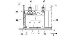
- This connection is made using an angle iron secondary connection 36 comprising a first secondary wing 37 and a second secondary wing 38 connected to the first secondary wing 37, the first secondary wing 37 being connected to the secondary sealing membrane 11 and the second secondary wing 38 being welded to a plate anchor 69 secured to the upper load-bearing wall 8, as shown in particular in .
- some strakes of the secondary sealing membrane 11 are interrupted by the opening 7 and are connected to the upper load-bearing wall 8.
- the secondary sealing membrane 11 is capable of transmitting to the secondary connecting angle 36 compressive and tensile forces related to the work of the secondary sealing membrane 11. These stresses are particularly great at the front longitudinal end edge 25 of the loading/unloading opening 7, which is the edge of the loading/unloading opening 7 located between the lid 19 and the front cofferdam wall 6 in the longitudinal direction L. Indeed, due to the placement of the cover 19 close to the rear cofferdam wall 5, the longitudinal dimension of the secondary sealing membrane 11 between the cover 19 and the front cofferdam wall 6 is much greater than the longitudinal dimension of the secondary sealing membrane 11 between the cover 19 and the rear cofferdam wall 5 which leads to greater forces at the level of the front longitudinal end edge 25 during deformation of the hull or thermal contraction.
- these forces on the front longitudinal end edge 25 are particularly significant due to the orientation of the secondary sealing membrane 11.
- the secondary sealing membrane 11 is oriented so that the central portion plane of the strakes extends in the longitudinal direction L of the vessel 70. Thus, no zone making it possible to absorb the tensile and compressive forces is provided in this direction.
- a special support structure is provided along the front longitudinal end edge 25 extending in the transverse direction T which will be detailed afterwards.
- FIGs 2, 3, 6 and 7 illustrate in particular the arrangement of this support structure at the level of the front longitudinal end edge 25 of the loading/unloading opening 7, according to different embodiments.
- the storage installation 1 comprises a plurality of metal secondary fixing supports 26 juxtaposed in the transverse direction T, extending at a distance from each other preferably at a regular interval, along the front longitudinal end edge 25 of loading/unloading opening 7.
- Each secondary fixing support 26 comprises a secondary cap 29 extending in the longitudinal direction L and which is welded to a secondary foot 30.
- the secondary foot 30 is anchored to the upper load-bearing wall 8 for example by welding or screwing.
- the secondary fixing support 26 thus has a seat length extending in the longitudinal direction L, measured at the level of the fixing of the secondary foot 30 to the supporting structure and making it possible to oppose tilting and bending in this direction.
- the secondary foot 30 is, as illustrated in FIGS. 4 and 5, made in the form of an H-section beam (shape of section in a plane orthogonal to the direction of thickness).
- the secondary foot 30 comprising a first branch 31 formed of a plate and a second branch 32 formed of a plate separated from the first branch 31 in the longitudinal direction L by a connecting plate 3.
- the spacing in the longitudinal direction L between the first branch 31 and the second branch 32 at the level of the upper load-bearing wall 8 corresponds to the seat length.
- Other cross-sectional shapes for the secondary foot 30 can also be used provided they offer a sufficient moment of inertia in the longitudinal direction L.
- the secondary thermally insulating barrier 10 comprises secondary insulating end blocks 34.
- Each secondary insulating end block 34 is interposed between two fixing supports 26 adjacent in the transverse direction T.
- a secondary stop plate 40 is fixed, by example by gluing, stapling, or screwing, to the upper surface of each end secondary insulating block 34.
- the secondary waterproofing membrane 11 comprises a secondary metal fixing plate 35 which is fixed to the upper surface of the secondary stop plate 40.
- the first wing 37 of the connecting angle 36 is welded to a first portion of the secondary metal fixing plate 35 while the strakes interrupted by the opening 7 are welded to a second portion of the secondary metal fixing plate 35, as illustrated in particular in .
- the secondary stop plate 40 is itself fixed at each of its transverse ends to a secondary cap 29 using a fixing device 41 pressing the secondary stop plate 40 against the secondary cap 29.
- the secondary fixing support 26 comprises an abutment device 42 fixed to the secondary cap 29.
- the secondary stop plate 40 is thus held in position in the longitudinal direction L by, on the one hand, the abutment device 42 and, on the other hand, by one end 43 of the first branch 31 of the secondary leg 30, the end 43 projecting from the secondary cap 29.
- the secondary stop plate 40 is rigidly supported by the fixing brackets 26 in the longitudinal direction L and in the direction of thickness, which makes it possible to take up the tensile or compressive force that can be exerted by the secondary membrane Operating.
- support plates 52 are positioned on either side of the second secondary wing 38 of the angles in order to stiffen it and prevent the angles from buckling in the thickness direction.
- support plates 52 are made of a material having a coefficient of thermal contraction in the direction of thickness close to the coefficient of thermal contraction of the angles so as to contract in a substantially identical manner and retain its support function, for example plywood when the angles are made of Invar ®.
- a support plate 52 is also positioned above the space between the cover 19 and the connecting angles 26, 49 in order to support the metal connecting strip 24. This space is filled with insulating packing 53, by example of glass wool blocks.
- the primary thermally insulating barrier 12 of the ceiling wall 4 comprises, in the same way as the secondary thermally insulating barrier 10, a primary insulating end block 39 adjacent to the front longitudinal end edge 25 of the loading opening/ unloading 7.
- the primary end insulating block 39 is located in line with the secondary end insulating block 34.
- the primary and secondary end insulating blocks 34, 39 are thus aligned at their edges facing the opening 7 .
- the primary end insulating block 39 is also formed in line with a first part of two secondary fixing supports 26, the secondary fixing supports 26 possibly being adjacent to one another or not. Indeed, the longitudinal dimension of the primary end insulating block 39 is less than the seat length of the secondary fixing support 26.
- the primary insulating block end 39 has two side walls perpendicular to the transverse direction T and which each has a protuberance 44 formed on a lower part of the side wall of the primary insulating block of end 39.
- the primary end insulating block 39 is anchored at each of these side walls using a first anchoring device 45 to a secondary cap 29.
- the primary insulating panel 18 directly adjacent to the insulating block end primary 39 is also anchored using a second anchoring device 46 to said secondary cap 29.
- the primary insulating panel 18 directly adjacent to the primary insulating end block 39 is formed in line with a second part of the secondary fixing support 26, the second part being connected to the first part in line with which the block is positioned. primary end insulator 39.
- the second part of the secondary fixing support 26 corresponds to an end portion of the secondary cap 29 farthest from the opening 7 in the longitudinal direction L so that the abutment device 42 is located between the first anchor device 45 and the second anchor device 46.
- the length of the primary end insulating block 39 is shorter than the length of the secondary end insulating block 34 in the longitudinal direction L.
- the secondary insulating panels 14 and the primary insulating panels 18 are staggered along the longitudinal direction L, which means that the interface between the end secondary insulation block 34 and the secondary insulation panel 14 is misaligned in the first direction with the interface between the end primary insulation block 39 and the primary insulation panel 18.
- the second anchor 46 is shown cut away to distinguish the interior.
- the first anchoring device 45 comprises a base 48 fixed to the secondary cap 29, a stud 49 fixed to said base 48 and developing along the direction of thickness and passing through in a sealed manner an orifice of the secondary sealing membrane 11, and a support element 50 mounted on the pin 49 and resting on a support surface formed on the protuberance 44 of the primary end insulating block 39 so as to retain it to the secondary fixing support 26.
- the second anchoring device 46 comprises a base 48 fixed to the secondary cap 29, a pin 49 fixed to said base 48 and developing along the direction of thickness and passing through an orifice in the membrane in a sealed manner.
- secondary seal 11, and a support element 50 mounted on the stud 49 and resting on a support surface formed on the primary insulating panel 18 adjacent to the primary insulating end block 39, so as to retain it at the support of secondary fixing 26.
- the support element 50 is for example made in the form of a plate retained on the stud 49 with the aid of a nut.
- the base 48 can be screwed to the secondary cap 29, as shown in , using fixing screws located on either side of the stud 49 in the transverse direction T.
- the base 48 can also be welded to the secondary cap 29.
- the orifice of the secondary sealing membrane 11 is provided through the primary metal fixing plate 35 while in the case of the second anchoring device 46, the orifice of the secondary sealing membrane 11 is provided through the end portion of one of the strakes interrupted by the opening 7.
- the first anchoring device 45 and the second anchoring device 46 further comprise a flange 54 which is engaged on the stud 49 and which is fixed in a sealed manner to the secondary sealing membrane 11 around the orifice of the secondary sealing membrane 11 and a deformable seal 55 sealingly connecting the flange 54 to the stud so as to allow relative movement between the flange 54 and the stud 49.
- the flange 54 is fixed in leaktight manner to the secondary sealing membrane 11 around the orifice of said secondary sealing membrane 11.
- This leaktight fastening is, for example, made by welding.
- stud 49 has an anchoring shoulder 56 projecting radially outwards from stud 49.
- deformable seal 55 is welded in a leaktight manner, on the one hand, to collar 54 and, on the other hand, on the other hand, to the anchoring shoulder 56 of the stud 49, which makes it possible to seal the passage of the stud 49 through the secondary sealing membrane 11.
- the deformable seal 55 is a bellows, for example made of stainless steel.
- the sealed connection between the secondary sealing membrane 11 and the stud 49 is flexible, which allows relative movements of the primary end insulating block 39 and of the adjacent primary insulating panel 18 with respect to the secondary sealing membrane 11 and thus makes it possible to limit the risks of degradation of the sealing of said secondary sealing membrane 11.
- the first anchoring device 45 and the second anchoring device 46 are also equipped with a bell 57 which has an orifice in which the stud 49 is threaded and which covers the said deformable seal 55.
- the bell 57 has a generally cylindrical shape.
- the anchoring device 45, 46 here comprises a collar 54 forming an integral part of the stud 49, that is to say that the collar 54 is made in the mass at the same time as the rest of the pin 49 and thus form a single piece.
- the collar 54 thus projects radially outwards from the pin 49 and is welded in a sealed manner to the secondary sealing membrane 11 around the orifice of the secondary sealing membrane 11.
- the device anchor 45, 46 has no deformable seal, no bell or anchoring shoulder.
- this anchoring can be carried out in different ways as illustrated in and in through two embodiments.
- said primary insulating panel 18 has a recess made in the foam 17 and the cover panel 16 at a lower corner 58 of said primary insulating panel 18 adjacent to the primary insulating end block.
- the lower corner 58 is provided with a cleat 59.
- the support element 50 of the second anchoring device 45 thus presses on a bearing surface formed on the cleat 59.
- said primary insulating panel 18 has a recess made in the foam 17 and in the cover panel 16 at a side face remote from the lower corner 58.
- the side face is perpendicular to the transverse direction T.
- a cleat 59 is fixed to the bottom panel 15 in the recess.
- the support element 50 of the second anchoring device 45 thus presses against a support surface formed on the cleat 59.
- the part of said primary insulating panel 18 located between the lower corner 58 and the cleat 59 can thus serve as adjustment zone in order to adjust the longitudinal dimension of the primary insulating panel 18.
- the secondary insulating panel 14 adjacent to the end secondary insulating block 34 also serves as an adjustment zone.
- said secondary insulating panel 14 may have a different structure both from the other secondary insulating panels 14 and also from the end secondary insulating block 34 so as to have a stiffness and/or a coefficient of thermal contraction in the thickness direction between that of the end secondary insulating block 34 and that of the other secondary insulating panels 14.
- the embodiment of the differs from the embodiment of the in that the secondary foot 30 is spaced from the anchor plate 69 in the longitudinal direction L by a greater distance. Indeed, in , the secondary foot 30 is spaced from the anchor plate 69 by a distance of 10 mm while in this distance has been increased to 20 mm in order to facilitate welding operations in this area. For this, a plywood or resin plate can be added between the secondary leg 30 and the second secondary wing 38.
- the end 43 of the first leg 31 of the secondary leg 30 can be a plate offset from the rest of the first branch 31 and welded thereto as shown in , or only one end offset from the rest of the second branch 31.
- a cutaway view of an LNG carrier 70 shows a sealed and insulated tank 71 of generally prismatic shape mounted in the double hull 72 of the ship.
- the wall of the tank 71 comprises a primary leaktight barrier intended to be in contact with the LNG contained in the tank, a secondary leaktight barrier arranged between the primary leaktight barrier and the double hull 72 of the ship, and two insulating barriers arranged respectively between the primary waterproof barrier and the secondary waterproof barrier and between the secondary waterproof barrier and the double hull 72.
- loading/unloading pipes 73 arranged on the upper deck of the ship can be connected, by means of appropriate connectors, to a maritime or port terminal to transfer a cargo of LNG from or to the tank 71.
- the represents an example of a maritime terminal comprising a loading and unloading station 75, an underwater pipeline 76 and an installation on land 77.
- the loading and unloading station 75 is a fixed offshore installation comprising a mobile arm 74 and a tower 78 which supports the mobile arm 74.
- the mobile arm 74 carries a bundle of insulated flexible pipes 79 which can be connected to the loading/unloading pipes 73.
- the orientable mobile arm 74 adapts to all sizes of LNG carriers.
- a connecting pipe, not shown, extends inside the tower 78.
- the loading and unloading station 75 allows the loading and unloading of the LNG carrier 70 from or to the shore installation 77.
- This comprises liquefied gas storage tanks 80 and connecting pipes 81 connected by the underwater pipe 76 to the loading or unloading station 75.
- the underwater pipe 76 allows the transfer of the liquefied gas between the loading or unloading station 75 and the shore installation 77 over a great distance, for example 5 km, which makes it possible to keep the LNG carrier 70 at a great distance from the coast during loading and unloading operations.
- pumps on board the ship 70 and/or pumps fitted to the shore installation 77 and/or pumps fitted to the loading and unloading station 75 are used.
Abstract
L'invention concerne une installation de stockage (1) comprenant une structure porteuse (2) et une cuve (71), la paroi de plafond (4) étant interrompue localement de manière à délimiter une ouverture (7), dans laquelle la barrière thermiquement isolante primaire (12) de la paroi de plafond (4) comporte un bloc isolant primaire d'extrémité (39) et un panneau isolant primaire, le bloc isolant primaire d'extrémité présentant un rigidité plus élevée que le panneau isolant primaire dans la direction d'épaisseur dans laquelle l'installation de stockage comporte au moins deux supports de fixation (26), chaque support de fixation (26) comportant un pied et un chapeau (29), dans laquelle le bloc isolant primaire d'extrémité est situé au droit d'une première partie d'un des supports de fixation et est fixé à l'aide d'un premier dispositif d'ancrage au chapeau, et le panneau isolant primaire s'étend au droit d'une deuxième partie dudit support de fixation, le panneau isolant primaire étant fixé à l'aide d'un deuxième dispositif d'ancrage au chapeau.
Description
L’invention se rapporte au domaine des installations de stockage pour gaz liquéfié comprenant une cuve étanche et thermiquement isolante, à membrane étanche. En particulier, l’invention se rapporte au domaine des cuves étanches et thermiquement isolantes pour le stockage et/ou le transport de gaz liquéfié à basse température, telles que des cuves pour le transport de Gaz de Pétrole Liquéfié (aussi appelé GPL) présentant par exemple une température comprise entre -50°C et 0°C, ou pour le transport de Gaz Naturel Liquéfié (GNL) à environ -162°C à pression atmosphérique. Ces cuves peuvent être installées à terre ou sur un ouvrage flottant. Dans le cas d’un ouvrage flottant, la cuve peut être destinée au transport de gaz liquéfié ou à recevoir du gaz liquéfié servant de carburant pour la propulsion de l’ouvrage flottant.
Il est connu de l’art antérieur, par exemple WO2019234360, des cuves étanches et thermiquement isolantes intégrées à la structure porteuse d’un navire, comprenant une barrière thermiquement isolante secondaire, une membrane d’étanchéité secondaire, une barrière thermiquement isolante primaire et une membrane d’étanchéité primaire. La cuve comporte une pluralité de parois de cuve assemblées les unes aux autres. La membrane d’étanchéité secondaire comporte une pluralité de virures parallèles. Chaque virure comporte une portion centrale plane s’étendant dans une première direction et deux bords relevés disposés de part et d’autre de la portion centrale plane et faisant saillie vers l’intérieur de la cuve par rapport à la portion centrale. Les virures sont ainsi juxtaposées selon un motif répété dans une deuxième direction et soudées ensemble au niveau des bords relevés. Une telle membrane d’étanchéité secondaire, communément appelée membrane tendue, ne possède pas dans la première direction de zones permettant d’absorber les efforts de traction et de compression contrairement à une membrane ondulée.
Dans ce type de structure, la membrane d’étanchéité secondaire est interrompue au niveau d’une ouverture afin, par exemple, de permettre la traversée de conduites de chargement/déchargement. Ainsi, au niveau de ces interruptions, la membrane d’étanchéité secondaire est arrêtée et est directement raccordée à la structure porteuse afin notamment de reprendre les efforts de traction et de compression résultant de la contraction thermique des membranes d’étanchéité, de la déformation de la coque liée par exemple au fléchissement de la poutre navire, et de l’état de remplissage des cuves.
Le document KR20200144178 décrit une paroi de cuve au niveau d’une telle interruption formée par un dôme liquide.
Une idée à la base de l’invention est de concevoir un support de la membrane d’étanchéité primaire à proximité d’une ouverture.
Une autre idée à la base de l’invention est de réaliser simplement le montage de la barrière thermiquement isolante primaire.
Selon un mode de réalisation, l’invention fournit une installation de stockage pour gaz liquéfié comprenant une structure porteuse métallique et une cuve étanche et thermiquement isolante agencée dans la structure porteuse,
la cuve comprenant dans une direction d’épaisseur de l’extérieur vers l’intérieur de la cuve, une barrière thermiquement isolante secondaire fixée à la structure porteuse, une membrane d’étanchéité secondaire métallique disposée sur la barrière thermiquement isolante secondaire, une barrière thermiquement isolante primaire disposée sur la membrane d’étanchéité secondaire, et une membrane d’étanchéité primaire disposée sur la barrière thermiquement isolante primaire et destinée à être en contact avec le gaz liquéfié,
la structure porteuse comportant une paroi porteuse supérieure,
la cuve comportant une paroi de plafond fixée à la paroi porteuse supérieure,
la paroi de plafond étant interrompue localement de manière à délimiter une ouverture de chargement/déchargement destinée à être traversée par des conduites de chargement/déchargement,
dans laquelle la barrière thermiquement isolante secondaire de la paroi de plafond comporte un bloc isolant secondaire d’extrémité adjacent à un bord de l’ouverture de chargement/déchargement, ledit bord s’étendant dans une deuxième direction, et un panneau isolant secondaire juxtaposé au bloc isolant secondaire d’extrémité dans une première direction, la première direction étant perpendiculaire à la deuxième direction,
dans laquelle la barrière thermiquement isolante primaire de la paroi de plafond comporte un bloc isolant primaire d’extrémité adjacent audit bord de l’ouverture de chargement/déchargement, et un panneau isolant primaire juxtaposé au bloc isolant primaire d’extrémité dans la première direction, le bloc isolant primaire d’extrémité présentant une rigidité plus élevée que le panneau isolant primaire dans la direction d’épaisseur
dans laquelle l’installation de stockage comporte une pluralité de, à savoir au moins deux, supports de fixation secondaires métalliques fixés à la paroi porteuse supérieure le long dudit bord de l’ouverture de chargement/déchargement et situés de part et d’autre du bloc isolant secondaire d’extrémité dans la deuxième direction, chaque support de fixation secondaire comportant un pied secondaire présentant une longueur d’assise s’étendant dans la première direction et comportant un chapeau secondaire fixé sur le pied secondaire,
dans laquelle le bloc isolant primaire d’extrémité est situé au droit d’une première partie d’un des supports de fixation secondaires et est fixé à l’aide d’un premier dispositif d’ancrage au chapeau secondaire dudit support de fixation secondaire, et le panneau isolant primaire s’étend au droit d’une deuxième partie dudit support de fixation secondaire, la deuxième partie étant adjacente à la première partie dans la première direction, le panneau isolant primaire étant fixé à l’aide d’un deuxième dispositif d’ancrage au chapeau secondaire.
Grâce à ces caractéristiques, le support de la membrane d’étanchéité primaire est réalisé en limitant l’apparition de marches dues aux différences de contraction thermique dans la direction d’épaisseur entre les différentes portions de la paroi de plafond. En effet, le support de fixation secondaire est ici surmonté à la fois du bloc isolant primaire d’extrémité et du panneau isolant primaire qui ont des rigidités différentes de sorte à former une zone de transition entre la portion de la paroi de plafond comportant uniquement des panneaux isolants et la portion de la paroi de plafond formée du support de fixation secondaire surmonté du bloc isolant primaire d’extrémité. De plus, l’ancrage du panneau isolant primaire est facilité car celui-ci vient s’ancrer directement sur le chapeau secondaire.
Selon des modes de réalisation, une telle installation de stockage peut comporter une ou plusieurs des caractéristiques suivantes.
Selon un mode de réalisation, la barrière thermiquement isolante secondaire comporte une plaque d’arrêt secondaire disposée sur le bloc isolant secondaire d’extrémité, une portion d’extrémité de la membrane d’étanchéité secondaire étant fixée à la plaque d’arrêt secondaire.
Selon un mode de réalisation, la membrane d’étanchéité secondaire de la paroi de plafond comporte une pluralité de virures parallèles s’étendant dans la première direction, chaque virure comportant une portion centrale plane et deux bords relevés faisant saillie vers l’intérieur de la cuve par rapport à la portion centrale, les virures étant juxtaposées dans la deuxième direction selon un motif répété et soudées ensemble de manière étanche au niveau des bords relevés, au moins une desdites virures étant interrompues par l’ouverture de chargement/déchargement.
Selon un mode de réalisation, une portion d’extrémité de ladite virure interrompue est fixée à la plaque d’arrêt secondaire.
Selon un mode de réalisation, le bloc isolant primaire d’extrémité est réalisé sous la forme d’une boite comprenant une plaque de fond, une plaque de couvercle parallèle à la plaque de fond et des plaques d’entretoises porteuses maintenant la plaque de couvercle à distance de la plaque de fond, la boite étant remplie de garniture isolante, par exemple de la perlite, des silices pyrogénées, des aérogels de silice ou de la laine de verre.
Selon un mode de réalisation, le panneau isolant primaire comporte successivement selon la direction d’épaisseur au moins une couche de mousse isolante et au moins une plaque rigide. Par exemple, le panneau isolant primaire comporte une couche de mousse isolante intercalée entre une plaque de fond et une plaque de couvercle.
Selon un mode de réalisation, la mousse isolante est une mousse polymère par exemple une mousse de polyuréthane. Selon un mode de réalisation, cette mousse isolante présente une densité supérieure à 100 kg/m3, de préférence supérieure ou égale à 120 kg/m3, notamment égale à 130 ou 150 ou 210 kg/m3.
Selon un mode de réalisation, la mousse isolante structurelle est une mousse renforcée, par exemple renforcée par des fibres telles que des fibres de verre.
Selon un mode de réalisation, le panneau de fond est un panneau de contreplaqué ou en composite avec fibres de verre. Selon un mode de réalisation, le panneau de couvercle est un panneau de contreplaqué ou en composite avec fibres de verre.
Selon un mode de réalisation, le coefficient de contraction thermique du bloc isolant primaire d’extrémité selon ladite direction d’épaisseur est inférieur au coefficient de contraction thermique selon ladite direction d’épaisseur du panneau isolante primaire.
Selon un mode de réalisation, le bloc isolant primaire d’extrémité est de forme parallélépipédique et comporte deux faces latérales perpendiculaire à la deuxième direction, au moins une des faces latérales étant fixée à l’aide du premier dispositif d’ancrage au chapeau secondaire du support de fixation secondaire.
Selon un mode de réalisation, une dimension du bloc isolant primaire d’extrémité dans la deuxième direction est égale à une distance entre deux supports de fixation secondaires adjacents, et les deux faces latérales du bloc isolant primaire d’extrémité sont fixées respectivement aux chapeaux secondaires des deux supports de fixation secondaires à l’aide de deux premiers dispositifs d’ancrage.
Selon un mode de réalisation, le bloc isolant primaire d’extrémité comporte une surface d’appui et le premier dispositif d’ancrage comporte une base fixée au chapeau secondaire, un goujon fixé à ladite base et se développant selon la direction d’épaisseur et traversant de manière étanche un orifice de la membrane d’étanchéité secondaire, et un élément d’appui monté sur le goujon et en appui sur la surface d’appui du bloc isolant primaire d’extrémité de manière à le retenir au support de fixation secondaire.
Selon un mode de réalisation, au moins une des faces latérales du bloc isolant primaire d’extrémité comporte une protubérance, la surface d’appui étant formé sur la protubérance.
Selon un mode de réalisation, le panneau isolant primaire comporte une surface d’appui et le deuxième dispositif d’ancrage comporte une base fixée au chapeau secondaire, un goujon fixé à ladite base et se développant selon la direction d’épaisseur et traversant de manière étanche un orifice de la membrane d’étanchéité secondaire, et un élément d’appui monté sur le goujon et en appui sur la surface d’appui du panneau isolant primaire de manière à le retenir au support de fixation secondaire.
Selon un mode de réalisation, la surface d’appui du panneau isolant primaire est située au niveau d’un coin ou à distance d’un coin du panneau isolant primaire.
Selon un mode de réalisation, le premier dispositif d’ancrage et/ou le deuxième dispositif d’ancrage comportent en outre une collerette faisant partie intégrante du goujon, la collerette faisant saillie radialement vers l’extérieur du goujon et étant fixée de manière étanche à la membrane d’étanchéité secondaire autour de l’orifice de la membrane d’étanchéité secondaire.
Selon un mode de réalisation, le premier dispositif d’ancrage et/ou le deuxième dispositif d’ancrage comportent en outre une collerette qui est engagée sur le goujon et qui est fixée de manière étanche à la membrane d’étanchéité secondaire autour de l’orifice de la membrane d’étanchéité secondaire et un joint déformable reliant de façon étanche la collerette au goujon de manière à autoriser un déplacement relatif entre la collerette et le goujon.
Selon un mode de réalisation, une interface entre le bloc isolant secondaire d’extrémité et le panneau isolant secondaire est située à une plus grande distance du bord de l’ouverture de chargement/déchargement dans la première direction qu’une interface entre le bloc isolant primaire d’extrémité et le panneau isolant primaire.
Selon un mode de réalisation, le premier dispositif d’ancrage et le deuxième dispositif d’ancrage sont formés de manière identique, le premier dispositif d’ancrage et le deuxième dispositif d’ancrage étant espacés l’un de l’autre dans la première direction.
Selon un mode de réalisation, l’installation de stockage comporte une cornière de raccordement s’étendant dans la deuxième direction pour séparer de manière étanche la barrière thermiquement isolante secondaire de l’ouverture de chargement/déchargement, la cornière de raccordement comprenant une première aile et une deuxième aile reliée à la première aile, la première aile étant fixée à la plaque d’arrêt secondaire et la deuxième aile étant soudée à un plat d’ancrage solidaire de la paroi porteuse supérieure.
Selon un mode de réalisation, le pied secondaire est espacé du plat d’ancrage dans la première direction, de préférence d’une distance supérieure ou égale à 15 mm, de manière plus préférentielle supérieure ou égale à 20 mm.
Selon un mode de réalisation, la barrière thermiquement isolante secondaire comporte le bloc isolant secondaire d’extrémité et des panneaux isolants secondaires, le panneau isolant secondaire adjacent au bloc isolant secondaire d’extrémité dans la première direction comportant une structure différente des autres panneaux isolants secondaires, par exemple de sorte à être d’une rigidité dans la direction d’épaisseur supérieure aux autres panneaux isolants secondaires ou à avoir un coefficient de contraction thermique plus faible.
Selon un mode de réalisation, une plaque de fixation secondaire métallique est fixée sur une surface supérieure de la plaque d’arrêt secondaire,
et une portion d’extrémité de la ou chaque virure interrompue par l’ouverture de chargement/déchargement est soudée à la plaque de fixation secondaire métallique.
et une portion d’extrémité de la ou chaque virure interrompue par l’ouverture de chargement/déchargement est soudée à la plaque de fixation secondaire métallique.
Selon un mode de réalisation, une plaque de fixation secondaire métallique est en alliage de fer avec du nickel par exemple de l’Invar, en alliage de fer avec du manganèse ou en inox.
Selon un mode de réalisation, le joint déformable comporte un soufflet déformable, ledit soufflet déformable étant creux et se développant autour et axialement le long du goujon. Le soufflet déformable est par exemple réalisé en acier inoxydable.
Selon un mode de réalisation, le premier dispositif d’ancrage et/ou le deuxième dispositif d’ancrage comporte une cloche recouvrant le soufflet déformable, la cloche présentant une forme cylindrique.
Selon un mode de réalisation, la base du premier dispositif d’ancrage et/ou du deuxième dispositif d’ancrage est fixée par vissage ou soudage au chapeau secondaire du support de fixation secondaire.
Selon un mode de réalisation, la longueur d’assise de la portion de support secondaire dans la première direction est supérieure ou égale à 300mm.
La membrane d’étanchéité primaire peut être réalisée de diverses manières. Selon un mode de réalisation, la membrane d’étanchéité primaire de la paroi de plafond comporte une pluralité de plaques métalliques ondulées juxtaposées dans la première direction et la deuxième direction, et soudées les unes aux autres, la membrane d’étanchéité primaire comportant une première série d’ondulations s’étendant dans la première direction et une deuxième série d’ondulations s’étendant dans la deuxième direction.
Selon un mode de réalisation, l’espacement entre deux supports de fixation secondaire adjacents dans la deuxième direction est égal à un multiple entier de la dimension d’une virure dans la deuxième direction, par exemple égal à la dimension d’une virure dans la deuxième direction.
Selon un mode de réalisation, la dimension d’une virure dans la deuxième direction est égale à 510mm.
Selon un mode de réalisation, la portion d’extrémité de la ou chaque virure soudée sur la plaque de fixation secondaire métallique présente une épaisseur supérieure à l’épaisseur de la virure à distance de l’ouverture de chargement/déchargement.
L’épaisseur est une dimension mesurée selon la direction d’épaisseur à savoir la direction perpendiculaire à la première direction et à la deuxième direction.
Selon un mode de réalisation, l’épaisseur de la portion d’extrémité est supérieure ou égale à 1,5mm. L’épaisseur des virures peut être inférieure à 1 mm à distance des extrémités, par exemple comprise entre 0,7 et 1 mm.
Selon un mode de réalisation, la cuve comporte un couvercle disposé dans l’ouverture de chargement/déchargement, le couvercle comportant une paroi d’étanchéité métallique et une structure d’isolation thermique située entre la paroi d’étanchéité et la paroi porteuse supérieure, le couvercle étant fixé à la paroi porteuse supérieure, la paroi d’étanchéité métallique étant raccordée de manière étanche à la membrane d’étanchéité primaire par une bande de liaison métallique.
Selon un mode de réalisation, la structure d’isolation thermique du couvercle comporte une pluralité de blocs isolants de couvercle, chaque bloc isolant de couvercle étant réalisé sous la forme d’une boite comprenant une plaque de couverture et une plaque de fond maintenues à distance par des plaques d’entretoises porteuses et des côtés de la boite, la boite étant remplie de garniture isolante.
Selon un mode de réalisation, la structure des blocs isolants de couvercle et la structure des blocs isolants primaires d’extrémité et/ou la structure des blocs isolants secondaires d’extrémité sont identiques. Par exemple, chaque bloc isolant de couvercle bloc isolant primaire d’extrémité sont réalisés sous la forme d’une boite en bois contreplaqué ou en matériau composite avec fibres de verre.
Ainsi, la contraction thermique dans la direction d’épaisseur est sensiblement proche ou égale entre les blocs isolants du couvercle et les blocs isolant formant le pourtour de l’ouverture de sorte à limiter le phénomène de marche dans cette zone.
Selon un mode de réalisation, la membrane d’étanchéité secondaire, la paroi d’étanchéité du couvercle et/ou la bande de liaison sont réalisées dans un métal à faible coefficient de dilatation, par exemple un alliage de fer et de nickel présentant un coefficient de dilatation thermique compris entre 0,5.10-6 et 2.10-6 K-1. Il est aussi possible d’utiliser des alliages de fer et de manganèse dont le coefficient de dilatation est typiquement de l’ordre de 7.10-6 K-1.
Selon un mode de réalisation, le support de fixation secondaire est réalisé en acier, par exemple en acier carboné ou en acier inoxydable.
Selon un mode de réalisation, la membrane d’étanchéité secondaire est réalisée en acier inoxydable.
Selon un mode de réalisation, la structure porteuse comporte une paroi de cofferdam arrière et une paroi de cofferdam avant situées de part et d’autre de la cuve dans la première direction, l’ouverture de chargement/déchargement étant formée à proximité d’une des parois de cofferdam, par exemple la paroi de cofferdam arrière, le support de fixation secondaire étant disposé entre l’ouverture et l’autre paroi de cofferdam, par exemple la paroi de cofferdam avant.
Ainsi, le support de fixation secondaire et la poutre d’arrêt secondaire permettent d’absorber les efforts de traction et de compression de la plus grande partie de la membrane d’étanchéité secondaire de la paroi de plafond, à savoir sur la portion s’étendant entre l’ouverture et la paroi de cofferdam avant.
Selon un mode de réalisation, le bord de l’ouverture de chargement/déchargement le long duquel est juxtaposée les supports de fixation secondaire est un bord d’extrémité longitudinale avant de l’ouverture de chargement/déchargement qui est situé entre l’ouverture et la paroi de cofferdam avant dans la première direction.
Une telle installation de stockage peut être une installation de stockage terrestre, par exemple pour stocker du GNL ou être une structure flottante, côtière ou en eau profonde, notamment un navire méthanier, une unité flottante de stockage et de regazéification (FSRU), une unité flottante de production et de stockage déporté (FPSO) et autres. Une telle installation peut aussi servir de réservoir de carburant dans tout type de navire.
Selon un mode de réalisation, l’installation de stockage précitée est réalisée sous la forme d’un ouvrage flottant, ladite structure porteuse étant constituée par une double coque de l’ouvrage flottant et la première direction est une direction longitudinale de l’ouvrage flottant.
Selon un mode de réalisation, l’ouvrage flottant est un navire pour le transport d’un produit liquide froid.
Selon un mode de réalisation, l’invention fournit aussi un système de transfert pour un produit liquide froid, le système comportant une installation de stockage précitée, des canalisations isolées agencées de manière à relier la cuve installée dans la coque du navire à une installation externe de stockage flottante ou terrestre et une pompe pour entrainer un flux de produit liquide froid à travers les canalisations isolées depuis ou vers l’installation externe de stockage flottante ou terrestre vers ou depuis la cuve du navire.
Selon un mode de réalisation, l’invention fournit aussi un procédé de chargement ou déchargement d’une installation de stockage précitée, dans lequel on achemine un produit liquide froid à travers des canalisations isolées depuis ou vers une installation externe de stockage flottante ou terrestre vers ou depuis la cuve du navire.
L’invention sera mieux comprise, et d'autres buts, détails, caractéristiques et avantages de celle-ci apparaîtront plus clairement au cours de la description suivante de plusieurs modes de réalisation particuliers de l’invention, donnés uniquement à titre illustratif et non limitatif, en référence aux dessins annexés.
Par convention, on appellera « sur » ou « au-dessus » ou « supérieur » une position située plus près de l’intérieur de la cuve et « sous » ou « en dessous » ou « inférieur » une position située plus près de la structure porteuse, quelle que soit l’orientation de la paroi de cuve par rapport au champ de gravité terrestre. Ainsi, les figures 2 à 7 sont représentées dans une orientation inversée par rapport à leur position réelle dans une installation de stockage.
La représente un navire 70 méthanier pour le stockage et le transport de gaz liquéfié. Toutefois, l’invention ne se limite pas à ce type de navire.
Le navire 70 représenté sur la comporte une installation de stockage 1 comportant quatre cuves 71 disposées dans la structure porteuse 2 formée par la coque interne du navire 70 et fixées à celle-ci. Chaque cuve 71 est de forme polyédrique et comporte une pluralité de parois de cuve assemblées les unes aux autres de sorte à former un espace interne 3, et notamment une paroi de plafond 4, une paroi de cofferdam arrière 5 et une paroi de cofferdam avant 6. Les parois de cofferdam avant 6 et arrière 5 sont espacées dans la direction longitudinale L du navire 70 et sont fixées en partie supérieure à la paroi de plafond 4. Pour le chargement et le déchargement de ces cuves 71, il est prévu une ouverture de chargement/déchargement 7 formée dans la paroi de plafond 4 afin de faire traverser des conduites de chargement/déchargement, les conduites pouvant être solidarisées sur une structure non représentée. La paroi de plafond 4 est fixée à une paroi porteuse supérieure 8 de la structure porteuse 2. La paroi porteuse supérieure 8 est également munie d’orifices permettant aux conduites de chargement/déchargement de traverser la structure porteuse 2.
L’ouverture de chargement/déchargement 7 sert de point de pénétration pour divers équipements de manutention du GNL, à savoir par exemple une ligne de remplissage, une ligne de pompage d’urgence, des lignes de déchargement liées à des pompes de déchargement, une ligne de pulvérisation, une ligne d’alimentation liée à une pompe de pulvérisation, etc. Le fonctionnement de ces équipements est connu par ailleurs.
L’ouverture de chargement/déchargement 7 est prévu dans la paroi de plafond 4 à proximité de la paroi de cofferdam arrière 5.
La représente une vue en perspective d’une paroi de plafond 4 depuis l’intérieur de la cuve selon un premier mode de réalisation, dans une zone à proximité d’une ouverture de chargement/déchargement 7.
Il va être par la suite décrit plus particulièrement la structure multicouche de la paroi de plafond 4.
La structure multicouche de la paroi de plafond 4 d’une cuve étanche et thermiquement isolante 71 de stockage d’un gaz liquéfié, tel que du gaz naturel liquéfié (GNL), comporte successivement, dans la direction d’épaisseur, depuis l’extérieur vers l’intérieur de la cuve, une barrière thermiquement isolante secondaire 10 retenue à la paroi porteuse supérieure 8, une membrane d’étanchéité secondaire 11 reposant sur la barrière thermiquement isolante secondaire 10, une barrière thermiquement isolante primaire 12 reposant sur la membrane d’étanchéité secondaire 11 et une membrane d’étanchéité primaire 13 reposant sur la barrière thermiquement isolante primaire 12 et destinée à être en contact avec le gaz naturel liquéfié contenu dans la cuve 71.
La barrière thermiquement isolante secondaire 10 comporte une pluralité de panneaux isolants secondaires 14 qui sont ancrés sur la paroi porteuse supérieure 8 au moyen de dispositifs d’ancrage 9. Les panneaux isolants secondaires 14 présentent une forme générale parallélépipédique et sont par exemple disposés selon des rangées parallèles dans la direction longitudinale L et dans la direction transversale T perpendiculaire à la direction longitudinale L.
La membrane d’étanchéité secondaire 11 de la paroi de plafond 4 comporte une nappe continue de virures métalliques, à bord relevés. Les virures comportent une portion centrale plane reposant sur les panneaux isolants secondaires 14 de la barrière thermiquement isolante secondaire 10 et comportent également deux bords relevés disposés de part et d’autre de la portion centrale plane dans la direction transversale T et faisant saillie vers l’intérieur de la cuve par rapport à la portion centrale. Les virures sont soudées par leurs bords relevés sur des supports de soudure parallèles qui sont fixés dans des rainures ménagées au niveau de la surface des panneaux isolants secondaires 14 en contact avec la membrane d’étanchéité secondaire 11. Les virures sont, par exemple, réalisées en Invar ® : c’est-à-dire un alliage de fer et de nickel dont le coefficient de dilatation est typiquement compris entre 1,2.10-6 et 2.10-6 K-1.
Sur la , on observe que la barrière thermiquement isolante primaire 12 de la paroi de plafond 4 comporte une pluralité de panneaux isolants primaires 18 qui sont ancrés aux panneaux isolants secondaires 14 au moyen de dispositifs de fixation 9. Les panneaux isolants primaires 18 présentent une forme générale parallélépipédique. En outre, ils peuvent présenter des dimensions sensiblement identiques à ou différentes de celles des panneaux isolants secondaires 14. Dans le mode représenté en , les panneaux isolants primaires 18 sont positionnés de manière décalée par rapport aux blocs isolants secondaires 14 dans la direction longitudinale L, et de manière optionnelle également dans la direction transversale T.
Dans le mode de réalisation représenté notamment en , les panneaux isolants secondaires 14 et les panneaux isolants primaires 18 comportent une plaque de fond 15, une plaque de couvercle 16 et une ou plusieurs couches de mousse polymère isolante 17 prises en sandwich entre la plaque de fond 15, la plaque de couvercle 16 et collées à celles-ci. La mousse polymère isolante 17 peut notamment être une mousse à base de polyuréthane, optionnellement renforcée par des fibres, notamment des fibres de verre.
Dans le mode de réalisation représenté en , les panneaux isolants secondaires 14 de la barrière thermiquement isolante secondaire 10 comportent au moins deux types de structure différente, par exemple la structure précitée et une structure sous forme de boite comportant une plaque de fond 15, une plaque de couvercle 16 et des plaques entretoises porteuses s’étendant, dans la direction d’épaisseur, entre la plaque de fond 15 et la plaque de couvercle 16 et délimitant une pluralité de compartiments remplis d’une garniture isolante, telle que de la perlite, de la laine de verre ou de roche. Ces différentes structures sont choisies en fonction de leur zone d’implantation dans la cuve. Dans un mode de réalisation non représenté, les panneaux isolants primaires 18 peuvent également comporter au moins deux types de structure différente. Des exemples d’une telle structure sont fournis dans la publication WO-A-2019077253.
Comme représenté en et en , la membrane d’étanchéité primaire 13 comporte une pluralité de plaques métalliques ondulées juxtaposées dans la direction longitudinale L et la direction transversale T, et soudées les unes aux autres. La membrane d’étanchéité primaire 13 comporte une première série d’ondulations 27 s’étendant dans la direction longitudinale L et une deuxième série d’ondulations 28 s’étendant dans la direction transversale T.
Afin de délimiter l’ouverture de chargement/déchargement 7, la paroi de plafond 4 est interrompue localement afin de permettre la traversée des conduites de chargement/déchargement. Ainsi, les membranes d’étanchéités 11, 13 et les barrières thermiquement isolantes 10, 12 sont interrompues tout autour de l’ouverture de chargement/déchargement 7, comme représenté sur la .
Afin d’assurer une continuité de l’étanchéité et de l’isolation au niveau de l’ouverture, la cuve 71 comporte un couvercle 19 disposé dans l’ouverture de chargement/déchargement 7. Le couvercle 19 comporte une paroi d’étanchéité métallique 20 et une structure d’isolation thermique 21 située entre la paroi d’étanchéité métallique 20 et la paroi porteuse supérieure 8. Le couvercle 19 est fixé à la paroi porteuse supérieure 8. La paroi d’étanchéité métallique 20 réalise la continuité de l’étanchéité avec la membrane d’étanchéité primaire 13 de la paroi de plafond 4 tandis que la structure d’isolation thermique 21 réalise la continuité de l’isolation.
La structure d’isolation thermique 21 peut comporter un ou plusieurs blocs isolants de couvercle 22, réalisé par exemple sous forme de boite comportant une plaque de fond, une plaque de couvercle et des plaques entretoises porteuses s’étendant, dans la direction d’épaisseur, entre la plaque de fond et la plaque de couvercle et délimitant une pluralité de compartiments remplis d’une garniture isolante, telle que de la perlite, de la laine de verre ou de roche. Le ou les blocs isolants de couvercle 22 comportent des trous de passage (non représentés) permettant le passage des conduites de chargement/déchargement.
La paroi d’étanchéité 20 du couvercle 19 comporte par exemple une pluralité de plaques planes métalliques soudées les unes aux autres. La paroi d’étanchéité 20 comporte de plus une pluralité d’orifices de couvercle (non représentés) destinés à être traversés par les conduites de chargement/déchargement. L’installation de stockage 1 comporte de plus une bande de liaison métallique 24 permettant de relier de manière étanche la paroi d’étanchéité 20 du couvercle et la membrane d’étanchéité primaire 13 de la paroi de plafond 4, comme visible sur la .
Si au niveau de l’ouverture de chargement/déchargement 7 la membrane d’étanchéité primaire 13 est raccordée à la paroi d’étanchéité 20 du couvercle 19, la membrane d’étanchéité secondaire 11 est quant à elle interrompue au niveau des bords de l’ouverture de chargement/déchargement 7 et est directement raccordée de manière étanche à la paroi porteuse supérieure 8 afin de rendre étanche la séparation entre la barrière thermiquement isolante secondaire 10 et le couvercle 19. Ce raccordement est réalisé à l’aide d’une cornière de raccordement secondaire 36 comportant une première aile secondaire 37 et une deuxième aile secondaire 38 reliée à la première aile secondaire 37, la première aile secondaire 37 étant raccordée à la membrane d’étanchéité secondaire 11 et la deuxième aile secondaire 38 étant soudée à un plat d’ancrage 69 solidaire de la paroi porteuse supérieure 8, comme représenté notamment en . Ainsi, certaines virures de la membrane d’étanchéité secondaires 11 sont interrompues par l’ouverture 7 et sont raccordées à la paroi porteuse supérieure 8.
Au niveau de ce raccordement à la paroi porteuse supérieure 8, la membrane d’étanchéité secondaire 11 est susceptible de transmettre à la cornière de raccordement secondaire 36 des efforts de compression et de traction liés au travail de la membrane d’étanchéité secondaire 11. Ces efforts sont particulièrement importants au niveau du bord d’extrémité longitudinale avant 25 de l’ouverture de chargement/déchargement 7, qui est le bord de l’ouverture de chargement/déchargement 7 situé entre le couvercle 19 et la paroi de cofferdam avant 6 dans la direction longitudinale L. En effet, du fait du placement du couvercle 19 proche de la paroi de cofferdam arrière 5, la dimension longitudinale de la membrane d’étanchéité secondaire 11 entre le couvercle 19 et la paroi de cofferdam avant 6 est bien plus importante que la dimension longitudinale de la membrane d’étanchéité secondaire 11 entre le couvercle 19 et la paroi de cofferdam arrière 5 ce qui entraine des efforts plus importants au niveau du bord d’extrémité longitudinale avant 25 lors de la déformation de la coque ou de la contraction thermique. De plus, ces efforts sur le bord d’extrémité longitudinale avant 25 sont particulièrement importants du fait de l’orientation de la membrane d’étanchéité secondaire 11. En effet, la membrane d’étanchéité secondaire 11 est orientée de sorte que la portion centrale plane des virures s’étende dans la direction longitudinale L du navire 70. Ainsi, aucune zone permettant d’absorber les efforts de traction et de compression n’est prévue dans cette direction.
Afin de soulager la cornière de raccordement secondaire 36 et la soudure avec la membrane d’étanchéité secondaire 11, il est prévu une structure de support particulière le long du bord d’extrémité longitudinale avant 25 s’étendant selon la direction transversale T qui sera détaillée par la suite.
Les figures 2, 3, 6 et 7 illustrent notamment la disposition de cette structure de support au niveau du bord d’extrémité longitudinale avant 25 de l’ouverture de chargement/déchargement 7, selon différents modes de réalisation.
L’installation de stockage 1 comporte une pluralité de supports de fixation secondaire 26 métalliques juxtaposés dans la direction transversale T, s’étendant à distance les uns des autres de préférence selon un intervalle régulier, le long du bord d’extrémité longitudinale avant 25 de l’ouverture de chargement/déchargement 7.
Chaque support de fixation secondaire 26 comporte un chapeau secondaire 29 s’étendant dans la direction longitudinale L et qui est soudé à un pied secondaire 30. Le pied secondaire 30 est ancré à la paroi porteuse supérieure 8 par exemple par soudage ou vissage. Le support de fixation secondaire 26 présente ainsi une longueur d’assise s’étendant selon la direction longitudinale L, mesurée au niveau de la fixation du pied secondaire 30 à la structure porteuse et permettant de s’opposer au basculement et à la flexion dans cette direction.
Le pied secondaire 30 est, comme illustré en figures 4 et 5, réalisé sous la forme de poutre à section en H (forme de section dans un plan orthogonal à la direction d’épaisseur). Le pied secondaire 30 comportant une première branche 31 formée d’une plaque et une deuxième branche 32 formée d’une plaque écartée de la première branche 31 dans la direction longitudinale L par une plaque de liaison 3. L’écartement dans la direction longitudinale L entre la première branche 31 et la deuxième branche 32 au niveau de la paroi porteuse supérieure 8 correspond à la longueur d’assise. D’autres formes de section pour le pied secondaire 30 peuvent également être utilisées à condition d’offrir un moment d’inertie suffisant dans la direction longitudinale L.
La barrière thermiquement isolante secondaire 10 comporte des blocs isolants secondaires d’extrémité 34. Chaque bloc isolant secondaire d’extrémité 34 est intercalé entre deux supports de fixation 26 adjacents dans la direction transversale T. Une plaque d’arrêt secondaire 40 est fixée, par exemple par collage, agrafage, ou vissage, à la surface supérieure de chaque bloc isolant secondaire d’extrémité 34.
La membrane d’étanchéité secondaire 11 comporte une plaque de fixation secondaire métallique 35 qui est fixée à la surface supérieure de la plaque d’arrêt secondaire 40. Ainsi, la première aile 37 de la cornière de raccordement 36 est soudée sur une première portion de la plaque de fixation secondaire métallique 35 tandis que les virures interrompues par l’ouverture 7 sont soudées sur une seconde portion de la plaque de fixation secondaire métallique 35, comme notamment illustré en .
La plaque d’arrêt secondaire 40 est quant à elle fixée à chacune de ses extrémités transversales à un chapeau secondaire 29 à l’aide d’un dispositif de fixation 41 venant plaquer la plaque d’arrêt secondaire 40 contre le chapeau secondaire 29.
Il est également prévu de bloquer la translation des plaques d’arrêt secondaires 40 dans la direction longitudinale L. Pour cela, le support de fixation secondaire 26 comporte un dispositif de butée 42 fixé sur le chapeau secondaire 29. La plaque d’arrêt secondaire 40 est ainsi maintenue en position dans la direction longitudinale L par d’une part le dispositif de butée 42 et d’autre par une extrémité 43 de la première branche 31 du pied secondaire 30, l’extrémité 43 faisant saillie du chapeau secondaire 29. Ainsi, la plaque d’arrêt secondaire 40 est supportée rigidement par les supports de fixation 26 dans la direction longitudinale L et dans la direction d’épaisseur, ce qui permet de reprendre l’effort de traction ou de compression pouvant être exercé par la membrane secondaire en fonctionnement.
Comme représenté notamment sur la , des plaques de support 52, par exemple en contreplaqué, sont positionnées de part et d’autre de la deuxième aile secondaire 38 des cornières afin de la rigidifier et empêcher le flambement des cornières dans la direction d’épaisseur. De plus, de telles plaques de support 52 sont réalisées dans un matériau ayant un coefficient de contraction thermique dans la direction d’épaisseur proche du coefficient de contraction thermique des cornières de sorte à se contracter de manière sensiblement identique et conserver sa fonction de support, par exemple le contreplaqué lorsque les cornières sont réalisées en Invar ®. Une plaque de support 52 est également positionnée au-dessus de l’espace situé entre le couvercle 19 et les cornières de raccordement 26, 49 afin de supporter la bande de liaison métallique 24. Cet espace est comblé avec de la garniture isolante 53, par exemple des blocs de laine de verre.
La barrière thermiquement isolante primaire 12 de la paroi de plafond 4 comporte, de la même manière que la barrière thermiquement isolante secondaire 10, un bloc isolant primaire d’extrémité 39 adjacent au bord d’extrémité longitudinale avant 25 de l’ouverture de chargement/déchargement 7. Le bloc isolant primaire d’extrémité 39 est situé au droit du bloc isolant secondaire d’extrémité 34. Les blocs isolants primaire et secondaire d’extrémité 34, 39 sont ainsi alignés au niveau de leurs bords tournés vers l’ouverture 7.
Le bloc isolant primaire d’extrémité 39 est également formé au droit d’une première partie de deux supports de fixation secondaire 26, les supports de fixation secondaire 26 pouvant être adjacents l’un à l’autre ou non. En effet, la dimension longitudinale du bloc isolant primaire d’extrémité 39 est inférieure à la longueur d’assise du support de fixation secondaire 26.
Il va être décrit plus en détail par la suite l’ancrage de la barrière thermiquement isolante primaire 12 à proximité du bord d’extrémité longitudinale avant 25.
Comme représenté sur les figures 3 et 6 notamment, le bloc isolant primaire d’extrémité 39 comporte deux parois latérales perpendiculaires à la direction transversale T et qui comporte chacune une protubérance 44 formée sur une partie inférieure de la paroi latérale du bloc isolant primaire d’extrémité 39.
Le bloc isolant primaire d’extrémité 39 est ancré au niveau de chacune de ces parois latérales à l’aide d’un premier dispositif d’ancrage 45 à un chapeau secondaire 29. De plus, le panneau isolant primaire 18 directement adjacent au bloc isolant primaire d’extrémité 39 est également ancré à l’aide d’un deuxième dispositif d’ancrage 46 audit chapeau secondaire 29.
Ainsi, le panneau isolant primaire 18 directement adjacent au bloc isolant primaire d’extrémité 39 est formé au droit d’une deuxième partie du support de fixation secondaire 26, la deuxième partie étant reliée à la première partie au droit de laquelle est positionné le bloc isolant primaire d’extrémité 39. La deuxième partie du support de fixation secondaire 26 correspond à une portion d’extrémité du chapeau secondaire 29 la plus éloignée de l’ouverture 7 dans la direction longitudinale L de sorte que le dispositif de butée 42 est situé entre le premier dispositif d’ancrage 45 et le deuxième dispositif d’ancrage 46.
Sur la , la longueur du bloc isolant primaire d’extrémité 39 est plus courte que la longueur du bloc isolant secondaire d’extrémité 34 dans la direction longitudinale L. Ainsi, les panneaux isolants secondaires 14 et les panneaux isolants primaires 18 sont disposés en quinconce selon la direction longitudinale L, ce qui signifie que l’interface entre le bloc isolant secondaire d’extrémité 34 et le panneau isolant secondaire 14 est désalignée dans la première direction avec l’interface entre le bloc isolant primaire d’extrémité 39 et le panneau isolant primaire 18.
La représente plus en détails selon un premier mode de réalisation le premier dispositif d’ancrage 45 et le deuxième dispositif d’ancrage 46 qui sont représentés en présence uniquement du support de fixation secondaire 26 sur lequel ils sont fixés. Le deuxième dispositif d’ancrage 46 est illustré de manière écorchée afin de distinguer l’intérieur.
Le premier dispositif d’ancrage 45 comporte une base 48 fixée au chapeau secondaire 29, un goujon 49 fixé à ladite base 48 et se développant selon la direction d’épaisseur et traversant de manière étanche un orifice de la membrane d’étanchéité secondaire 11, et un élément d’appui 50 monté sur le goujon 49 et en appui sur une surface d’appui formé sur la protubérance 44 du bloc isolant primaire d’extrémité 39 de manière à le retenir au support de fixation secondaire 26.
De la même manière, le deuxième dispositif d’ancrage 46 comporte une base 48 fixée au chapeau secondaire 29, un goujon 49 fixé à ladite base 48 et se développant selon la direction d’épaisseur et traversant de manière étanche un orifice de la membrane d’étanchéité secondaire 11, et un élément d’appui 50 monté sur le goujon 49 et en appui sur une surface d’appui formé sur le panneau isolant primaire 18 adjacent bloc isolant primaire d’extrémité 39 , de manière à le retenir au support de fixation secondaire 26. L’élément d’appui 50 est par exemple réalisé sous la forme d’une plaque retenue au goujon 49 à l’aide d’un écrou. La base 48 peut être vissé au chapeau secondaire 29, comme représenté en , à l’aide de vis de fixation situé de part et d’autre du goujon 49 dans la direction transversale T. La base 48 peut également être soudée au chapeau secondaire 29.
Dans le cas du premier dispositif d’ancrage 45, l’orifice de la membrane d’étanchéité secondaire 11 est ménagé au travers de la plaque de fixation primaire métallique 35 tandis que dans le cas du deuxième dispositif d’ancrage 46, l’orifice de la membrane d’étanchéité secondaire 11 est ménagé au travers la portion d’extrémité d’une des virures interrompues par l’ouverture 7.
Comme représenté en , le premier dispositif d’ancrage 45 et le deuxième dispositif d’ancrage 46 comportent en outre une collerette 54 qui est engagée sur le goujon 49 et qui est fixée de manière étanche à la membrane d’étanchéité secondaire 11 autour de l’orifice de la membrane d’étanchéité secondaire 11 et un joint déformable 55 reliant de façon étanche la collerette 54 au goujon de manière à autoriser un déplacement relatif entre la collerette 54 et le goujon 49.
La collerette 54 est fixée de manière étanche sur la membrane d’étanchéité secondaire 11 autour de l’orifice de ladite membrane d’étanchéité secondaire 11. Cette fixation étanche est, par exemple, réalisée par soudure. Par ailleurs, le goujon 49 présente un épaulement d’ancrage 56 faisant saillie radialement vers l’extérieur du goujon 49. En outre, le joint déformable 55 est soudé de manière étanche, d’une part, à la collerette 54 et, d’autre part, à l’épaulement d’ancrage 56 du goujon 49, ce qui permet d’assurer l’étanchéité de la traversée du goujon 49 à travers la membrane d’étanchéité secondaire 11. Dans le mode de réalisation représenté en , le joint déformable 55 est un soufflet, par exemple en acier inoxydable. Ainsi, la liaison étanche entre la membrane d’étanchéité secondaire 11 et le goujon 49 est souple ce qui autorise des mouvements relatifs du bloc isolant primaire d’extrémité 39 et du panneau isolant primaire 18 adjacent par rapport à la membrane d’étanchéité secondaire 11 et permet ainsi de limiter les risques de dégradation de l’étanchéité de ladite membrane d’étanchéité secondaire 11.
Afin de protéger le joint déformable 55, le premier dispositif d’ancrage 45 et le deuxième dispositif d’ancrage 46 sont également équipés d’une cloche 57 qui présente un orifice dans lequel est enfilé le goujon 49 et qui recouvre ledit joint déformable 55. Dans le mode de réalisation représenté, la cloche 57 présente une forme générale cylindrique.
La représente un deuxième mode de réalisation pour le premier dispositif d’ancrage 45 et le deuxième dispositif d’ancrage 46. Sur cette figure, seule une partie de la base 48 est représentée.
Contrairement au premier mode de réalisation de la , dans ce mode de réalisation, le dispositif d’ancrage 45, 46 comporte ici une collerette 54 faisant partie intégrante du goujon 49, c’est-à-dire que la collerette 54 est réalisée dans la masse en même temps que le reste du goujon 49 et forment ainsi une seule et même pièce. La collerette 54 fait ainsi saillie radialement vers l’extérieur du goujon 49 et est soudée de manière étanche à la membrane d’étanchéité secondaire 11 autour de l’orifice de la membrane d’étanchéité secondaire 11. Dans ce mode de réalisation, le dispositif d’ancrage 45, 46 ne comporte ni joint déformable, ni cloche ni épaulement d’ancrage.
Concernant l’ancrage du panneau isolant primaire 18 adjacent au bloc isolant primaire d’extrémité 39, cet ancrage peut être réalisé de différentes manières comme illustrés en et en au travers de deux modes de réalisation.
Dans le mode de réalisation de la , ledit panneau isolant primaire 18 comporte un évidement réalisé dans la mousse 17 et le panneau de couvercle 16 au niveau d’un coin inférieur 58 dudit panneau isolant primaire 18 adjacent au bloc isolant primaire d’extrémité. Le coin inférieur 58 est muni d’un tasseau 59. L’élément d’appui 50 du deuxième dispositif d’ancrage 45 vient ainsi appuyer sur une surface d’appui formé sur le tasseau 59.
Dans le mode de réalisation de la , ledit panneau isolant primaire 18 comporte un évidement réalisé dans la mousse 17 et dans le panneau de couvercle 16 au niveau d’une face latérale à distance du coin inférieur 58. La face latérale est perpendiculaire à la direction transversale T. Un tasseau 59 est fixé au panneau de fond 15 dans l’évidement. L’élément d’appui 50 du deuxième dispositif d’ancrage 45 vient ainsi appuyer sur une surface d’appui formé sur le tasseau 59. La partie dudit panneau isolant primaire 18 située entre le coin inférieur 58 et le tasseau 59 peut ainsi servir de zone de réglage afin d’ajuster la dimension longitudinale du panneau isolant primaire 18. Dans la barrière thermiquement isolante secondaire 10, le panneau isolant secondaire 14 adjacent au bloc isolant secondaire d’extrémité 34 sert également de zone de réglage. De plus, comme représenté en , ledit panneau isolant secondaire 14 peut avoir une structure différente à la fois des autres panneaux isolants secondaires 14 et également du bloc isolant secondaire d’extrémité 34 de sorte à avoir une rigidité et/ou un coefficient de contraction thermique dans la direction d’épaisseur compris entre celui du bloc isolant secondaire d’extrémité 34 et celui des autres panneaux isolants secondaires 14.
Le mode de réalisation de la diffère du mode de réalisation de la en ce que le pied secondaire 30 est espacé du plat d’ancrage 69 dans la direction longitudinale L d’une distance plus importante. En effet, en , le pied secondaire 30 est espacé du plat d’ancrage 69 d’une distance de 10 mm tandis qu’en cette distance a été portée à 20 mm afin de faciliter les opérations de soudage dans cette zone. Pour cela, une plaque de contreplaqué ou de la résine peut être ajouté entre le pied secondaire 30 et la deuxième aile secondaire 38. De plus l’extrémité 43 de la première branche 31 du pied secondaire 30 peut être une plaque déportée par rapport au reste de la première branche 31 et soudée à celle-ci comme représenté en , ou seulement une extrémité déportée par rapport au reste de la deuxième branche 31.
En référence à la , une vue écorchée d’un navire méthanier 70 montre une cuve étanche et isolée 71 de forme générale prismatique montée dans la double coque 72 du navire. La paroi de la cuve 71 comporte une barrière étanche primaire destinée à être en contact avec le GNL contenu dans la cuve, une barrière étanche secondaire agencée entre la barrière étanche primaire et la double coque 72 du navire, et deux barrières isolante agencées respectivement entre la barrière étanche primaire et la barrière étanche secondaire et entre la barrière étanche secondaire et la double coque 72.
De manière connue en soi, des canalisations de chargement/déchargement 73 disposées sur le pont supérieur du navire peuvent être raccordées, au moyen de connecteurs appropriées, à un terminal maritime ou portuaire pour transférer une cargaison de GNL depuis ou vers la cuve 71.
La représente un exemple de terminal maritime comportant un poste de chargement et de déchargement 75, une conduite sous-marine 76 et une installation à terre 77. Le poste de chargement et de déchargement 75 est une installation fixe off-shore comportant un bras mobile 74 et une tour 78 qui supporte le bras mobile 74. Le bras mobile 74 porte un faisceau de tuyaux flexibles isolés 79 pouvant se connecter aux canalisations de chargement/déchargement 73. Le bras mobile 74 orientable s'adapte à tous les gabarits de méthaniers. Une conduite de liaison non représentée s'étend à l'intérieur de la tour 78. Le poste de chargement et de déchargement 75 permet le chargement et le déchargement du méthanier 70 depuis ou vers l'installation à terre 77. Celle-ci comporte des cuves de stockage de gaz liquéfié 80 et des conduites de liaison 81 reliées par la conduite sous-marine 76 au poste de chargement ou de déchargement 75. La conduite sous-marine 76 permet le transfert du gaz liquéfié entre le poste de chargement ou de déchargement 75 et l'installation à terre 77 sur une grande distance, par exemple 5 km, ce qui permet de garder le navire méthanier 70 à grande distance de la côte pendant les opérations de chargement et de déchargement.
Pour engendrer la pression nécessaire au transfert du gaz liquéfié, on met en œuvre des pompes embarquées dans le navire 70 et/ou des pompes équipant l'installation à terre 77 et/ou des pompes équipant le poste de chargement et de déchargement 75.
Bien que l'invention ait été décrite en liaison avec plusieurs modes de réalisation particuliers, il est bien évident qu'elle n'y est nullement limitée et qu'elle comprend tous les équivalents techniques des moyens décrits ainsi que leurs combinaisons si celles-ci entrent dans le cadre de l'invention.
L’usage du verbe « comporter », « comprendre » ou « inclure » et de ses formes conjuguées n’exclut pas la présence d’autres éléments ou d’autres étapes que ceux énoncés dans une revendication.
Dans les revendications, tout signe de référence entre parenthèses ne saurait être interprété comme une limitation de la revendication.
Claims (19)
- Installation de stockage (1) pour gaz liquéfié comprenant une structure porteuse (2) métallique et une cuve (71) étanche et thermiquement isolante agencée dans la structure porteuse,
la cuve comprenant dans une direction d’épaisseur de l’extérieur vers l’intérieur de la cuve, une barrière thermiquement isolante secondaire (10) fixée à la structure porteuse (2), une membrane d’étanchéité secondaire (11) métallique disposée sur la barrière thermiquement isolante secondaire (10), une barrière thermiquement isolante primaire (12) disposée sur la membrane d’étanchéité secondaire (11), et une membrane d’étanchéité primaire (13) disposée sur la barrière thermiquement isolante primaire (12) et destinée à être en contact avec le gaz liquéfié,
la structure porteuse comportant une paroi porteuse supérieure (8),
la cuve (71) comportant une paroi de plafond (4) fixée à la paroi porteuse supérieure (8),
la paroi de plafond (4) étant interrompue localement de manière à délimiter une ouverture de chargement/déchargement (7) destinée à être traversée par des conduites de chargement/déchargement,
dans laquelle la barrière thermiquement isolante secondaire (10) de la paroi de plafond (4) comporte un bloc isolant secondaire d’extrémité (34) adjacent à un bord (25) de l’ouverture de chargement/déchargement (7), et un panneau isolant secondaire (14) juxtaposé au bloc isolant secondaire d’extrémité (34) dans une première direction, ledit bord de l’ouverture de chargement/déchargement s’étendant dans une deuxième direction (T), la première direction étant perpendiculaire à la deuxième direction (T),
dans laquelle la barrière thermiquement isolante primaire (12) de la paroi de plafond (4) comporte un bloc isolant primaire d’extrémité (39) adjacent audit bord de l’ouverture de chargement/déchargement (7), et un panneau isolant primaire (18) juxtaposé au bloc isolant primaire d’extrémité (39) dans la première direction (L), le bloc isolant primaire d’extrémité (39) présentant un rigidité plus élevée que le panneau isolant primaire (18) dans la direction d’épaisseur,
dans laquelle l’installation de stockage comporte une pluralité de supports de fixation secondaires métalliques (26) fixés à la paroi porteuse supérieure (8) le long dudit bord de l’ouverture de chargement/déchargement (7) et situés de part et d’autre du bloc isolant secondaire d’extrémité (34) dans la deuxième direction (T), chaque support de fixation secondaire (26) comportant un pied secondaire (30) présentant une longueur d’assise s’étendant dans la première direction (L) et comportant un chapeau secondaire (29) fixé sur le pied secondaire (30),
dans laquelle le bloc isolant primaire d’extrémité (39) est situé au droit d’une première partie d’un des supports de fixation secondaires (26) et est fixé à l’aide d’un premier dispositif d’ancrage (45) au chapeau secondaire (29) dudit support de fixation secondaire (26), et le panneau isolant primaire (18) s’étend au droit d’une deuxième partie dudit support de fixation secondaire (26), la deuxième partie étant adjacente à la première partie dans la première direction (L), le panneau isolant primaire (18) étant fixé à l’aide d’un deuxième dispositif d’ancrage (46) au chapeau secondaire (29). - Installation de stockage selon la revendication 1, dans laquelle la barrière thermiquement isolante secondaire comporte une plaque d’arrêt secondaire (40) disposée sur le bloc isolant secondaire d’extrémité (34), une portion d’extrémité de la membrane d’étanchéité secondaire étant fixée à la plaque d’arrêt secondaire (40).
- Installation de stockage selon la revendication 2, dans laquelle la membrane d’étanchéité secondaire (11) de la paroi de plafond (4) comporte une pluralité de virures parallèles s’étendant dans la première direction (L), chaque virure comportant une portion centrale plane et deux bords relevés faisant saillie vers l’intérieur de la cuve par rapport à la portion centrale, les virures étant juxtaposées dans la deuxième direction (T) selon un motif répété et soudées ensemble de manière étanche au niveau des bords relevés, au moins une desdites virures étant interrompues par l’ouverture de chargement/déchargement, une portion d’extrémité de ladite virure interrompue étant fixée à la plaque d’arrêt secondaire (83).
- Installation de stockage selon l’une des revendications 1 à 3, dans laquelle le bloc isolant primaire d’extrémité (39) est réalisé sous la forme d’une boite comprenant une plaque de fond, une plaque de couvercle parallèle à la plaque de fond et des plaques d’entretoises porteuses maintenant la plaque de couvercle à distance de la plaque de fond, la boite étant remplie de garniture isolante.
- Installation de stockage selon l’une des revendications 1 à 4, dans laquelle le panneau isolant primaire (18) comporte successivement selon la direction d’épaisseur au moins une couche de mousse isolante (17) et au moins une plaque rigide (15, 16).
- Installation de stockage selon l’une des revendications 1 à 5, dans laquelle le bloc isolant primaire d’extrémité (39) est de forme parallélépipédique et comporte deux faces latérales perpendiculaire à la deuxième direction (T), au moins une des faces latérales étant fixée à l’aide du premier dispositif d’ancrage (45) au chapeau secondaire (29) du support de fixation secondaire (26).
- Installation de stockage selon la revendication 6, dans laquelle une dimension du bloc isolant primaire d’extrémité (39) dans la deuxième direction est égale à une distance entre deux supports de fixation secondaires (26) adjacents, et dans laquelle les deux faces latérales du bloc isolant primaire d’extrémité (39) sont fixées respectivement aux chapeaux secondaires (29) des deux supports de fixation secondaires (26) à l’aide de deux premiers dispositifs d’ancrage (45).
- Installation de stockage selon l’une des revendications 1 à 7, dans laquelle le bloc isolant primaire d’extrémité (39) comporte une surface d’appui et dans laquelle le premier dispositif d’ancrage (45) comporte une base (48) fixée au chapeau secondaire (29), un goujon (49) fixé à ladite base et se développant selon la direction d’épaisseur et traversant de manière étanche un orifice de la membrane d’étanchéité secondaire (11), et un élément d’appui (50) monté sur le goujon et en appui sur la surface d’appui du bloc isolant primaire d’extrémité (39) de manière à le retenir au support de fixation secondaire (26).
- Installation de stockage selon les revendications 6 et 8 prises en combinaison, dans laquelle au moins une des faces latérales du bloc isolant primaire d’extrémité (39) comporte une protubérance (44), la surface d’appui étant formé sur la protubérance.
- Installation de stockage selon l’une des revendications 1 à 9, dans laquelle le panneau isolant primaire (18) comporte une surface d’appui et dans laquelle le deuxième dispositif d’ancrage (46) comporte une base (48) fixée au chapeau secondaire (29), un goujon (49) fixé à ladite base et se développant selon la direction d’épaisseur et traversant de manière étanche un orifice de la membrane d’étanchéité secondaire, et un élément d’appui (50) monté sur le goujon et en appui sur la surface d’appui du panneau isolant primaire de manière à retenir le panneau isolant primaire au support de fixation secondaire (26).
- Installation de stockage selon la revendication 10, dans laquelle la surface d’appui du panneau isolant primaire (18) est situé au niveau d’un coin (58) ou à distance d’un coin du panneau isolant primaire.
- Installation de stockage selon l’une des revendications 8 à 11, dans laquelle le premier dispositif d’ancrage (45) et/ou le deuxième dispositif d’ancrage (46) comportent en outre une collerette (54) faisant partie intégrante du goujon, la collerette faisant saillie radialement vers l’extérieur du goujon et étant fixée de manière étanche à la membrane d’étanchéité secondaire autour de l’orifice de la membrane d’étanchéité secondaire.
- Installation de stockage selon l’une des revendications 1 à 12, dans laquelle une interface entre le bloc isolant secondaire d’extrémité (34) et le panneau isolant secondaire (14) est située à une plus grande distance du bord de l’ouverture de chargement/déchargement (7) dans la première direction qu’une interface entre le bloc isolant primaire d’extrémité (39) et le panneau isolant primaire (18).
- Installation de stockage selon l’une des revendications 1 à 13, dans laquelle le premier dispositif d’ancrage (45) et le deuxième dispositif d’ancrage (46) sont formés de manière identique, le premier dispositif d’ancrage et le deuxième dispositif d’ancrage étant espacés l’un de l’autre dans la première direction (L).
- Installation de stockage selon l’une des revendications 1 à 14 prise en combinaison avec la revendication 2, dans laquelle l’installation de stockage comporte une cornière de raccordement (36) s’étendant dans la deuxième direction (T) pour séparer de manière étanche la barrière thermiquement isolante secondaire de l’ouverture de chargement/déchargement, la cornière de raccordement comprenant une première aile (37) et une deuxième aile (38) reliée à la première aile, la première aile étant fixée à la plaque d’arrêt secondaire (40) et la deuxième aile étant soudée à un plat d’ancrage (69) solidaire de la paroi porteuse supérieure.
- Installation de stockage selon la revendication 15, dans laquelle le pied secondaire (30) est espacé du plat d’ancrage (69) dans la première direction (L), de préférence d’une distance supérieure ou égale à 15 mm, de manière plus préférentielle supérieure ou égale à 20 mm.
- Installation de stockage (1) selon l’une des revendications 1 à 16 réalisée sous la forme d’un ouvrage flottant, dans laquelle ladite structure porteuse est constituée par une double coque (72) de l’ouvrage flottant et dans laquelle la première direction (L) est une direction longitudinale (L) de l’ouvrage flottant, l’ouvrage flottant étant de préférence un navire (70) pour le transport d’un produit liquide froid.
- Système de transfert pour un produit liquide froid, le système comportant une installation de stockage selon la revendication 17, des canalisations isolées (73, 79, 76, 81) agencées de manière à relier la cuve (71) installée dans la coque de l’ouvrage flottant à une installation externe de stockage flottante ou terrestre (77) et une pompe pour entrainer un flux de produit liquide froid à travers les canalisations isolées depuis ou vers l’installation externe de stockage flottante ou terrestre vers ou depuis la cuve de l’ouvrage flottant.
- Procédé de chargement ou déchargement d’une installation de stockage selon la revendication 17, dans lequel on achemine un produit liquide froid à travers des canalisations isolées (73, 79, 76, 81) depuis ou vers une installation externe de stockage flottante ou terrestre (77) vers ou depuis la cuve (71) de l’ouvrage flottant.
Priority Applications (2)
| Application Number | Priority Date | Filing Date | Title |
|---|---|---|---|
| KR1020247001472A KR20240035996A (ko) | 2021-07-19 | 2022-07-13 | 액화 가스용 저장 설비 |
| CN202280050804.5A CN117813463A (zh) | 2021-07-19 | 2022-07-13 | 用于液化气体的储存设备 |
Applications Claiming Priority (2)
| Application Number | Priority Date | Filing Date | Title |
|---|---|---|---|
| FR2107746A FR3125323B1 (fr) | 2021-07-19 | 2021-07-19 | Installation de stockage pour gaz liquéfié |
| FRFR2107746 | 2021-07-19 |
Publications (1)
| Publication Number | Publication Date |
|---|---|
| WO2023001678A1 true WO2023001678A1 (fr) | 2023-01-26 |
Family
ID=77411924
Family Applications (1)
| Application Number | Title | Priority Date | Filing Date |
|---|---|---|---|
| PCT/EP2022/069695 WO2023001678A1 (fr) | 2021-07-19 | 2022-07-13 | Installation de stockage pour gaz liquéfié |
Country Status (5)
| Country | Link |
|---|---|
| KR (1) | KR20240035996A (fr) |
| CN (1) | CN117813463A (fr) |
| FR (1) | FR3125323B1 (fr) |
| TW (1) | TW202314156A (fr) |
| WO (1) | WO2023001678A1 (fr) |
Citations (6)
| Publication number | Priority date | Publication date | Assignee | Title |
|---|---|---|---|---|
| KR20180073950A (ko) * | 2016-12-23 | 2018-07-03 | 대우조선해양 주식회사 | 리퀴드 돔 체어 및 이를 이용한 단열박스 고정방법 |
| KR20190031008A (ko) * | 2017-09-15 | 2019-03-25 | 대우조선해양 주식회사 | 멤브레인형 액화천연가스 화물창 단열시스템의 리퀴드 돔 및 그의 리퀴드 돔 박스 밀폐방법 |
| WO2019077253A1 (fr) | 2017-10-20 | 2019-04-25 | Gaztransport Et Technigaz | Cuve etanche et thermiquement isolante a plusieurs zones |
| WO2019234360A2 (fr) | 2018-06-06 | 2019-12-12 | Gaztransport Et Technigaz | Cuve etanche et thermiquement isolante |
| KR20200144178A (ko) | 2019-06-17 | 2020-12-29 | 대우조선해양 주식회사 | Lng 저장탱크의 단열시스템 |
| KR20200144697A (ko) * | 2019-06-19 | 2020-12-30 | 대우조선해양 주식회사 | Lng 저장탱크의 단열시스템 |
-
2021
- 2021-07-19 FR FR2107746A patent/FR3125323B1/fr active Active
-
2022
- 2022-07-13 KR KR1020247001472A patent/KR20240035996A/ko unknown
- 2022-07-13 WO PCT/EP2022/069695 patent/WO2023001678A1/fr active Application Filing
- 2022-07-13 CN CN202280050804.5A patent/CN117813463A/zh active Pending
- 2022-07-15 TW TW111126658A patent/TW202314156A/zh unknown
Patent Citations (6)
| Publication number | Priority date | Publication date | Assignee | Title |
|---|---|---|---|---|
| KR20180073950A (ko) * | 2016-12-23 | 2018-07-03 | 대우조선해양 주식회사 | 리퀴드 돔 체어 및 이를 이용한 단열박스 고정방법 |
| KR20190031008A (ko) * | 2017-09-15 | 2019-03-25 | 대우조선해양 주식회사 | 멤브레인형 액화천연가스 화물창 단열시스템의 리퀴드 돔 및 그의 리퀴드 돔 박스 밀폐방법 |
| WO2019077253A1 (fr) | 2017-10-20 | 2019-04-25 | Gaztransport Et Technigaz | Cuve etanche et thermiquement isolante a plusieurs zones |
| WO2019234360A2 (fr) | 2018-06-06 | 2019-12-12 | Gaztransport Et Technigaz | Cuve etanche et thermiquement isolante |
| KR20200144178A (ko) | 2019-06-17 | 2020-12-29 | 대우조선해양 주식회사 | Lng 저장탱크의 단열시스템 |
| KR20200144697A (ko) * | 2019-06-19 | 2020-12-30 | 대우조선해양 주식회사 | Lng 저장탱크의 단열시스템 |
Also Published As
| Publication number | Publication date |
|---|---|
| FR3125323A1 (fr) | 2023-01-20 |
| KR20240035996A (ko) | 2024-03-19 |
| CN117813463A (zh) | 2024-04-02 |
| TW202314156A (zh) | 2023-04-01 |
| FR3125323B1 (fr) | 2023-06-16 |
Similar Documents
| Publication | Publication Date | Title |
|---|---|---|
| WO2017103500A1 (fr) | Bloc isolant convenant pour realiser une paroi isolante dans une cuve etanche | |
| WO2014096600A1 (fr) | Cuve etanche et thermiquement isolante | |
| WO2019110894A1 (fr) | Cuve étanche et thermiquement isolante | |
| WO2019155154A1 (fr) | Installation pour le stockage et le transport d'un gaz liquefie | |
| EP3473915A1 (fr) | Cuve etanche et thermiquement isolante | |
| EP3942219B1 (fr) | Cuve étanche et thermiquement isolante | |
| WO2020039134A1 (fr) | Paroi de cuve étanche et thermiquement isolante | |
| WO2019239048A1 (fr) | Cuve etanche et thermiquement isolante | |
| WO2017174938A1 (fr) | Cuve étanche et thermiquement isolante | |
| WO2020193665A1 (fr) | Cuve étanche et thermiquement isolante | |
| EP3707425A1 (fr) | Cuve etanche et thermiquement isolante comportant des dispositifs d'ancrage des panneaux isolants primaires sur des panneaux isolants secondaires | |
| FR3090810A1 (fr) | Système d’ancrage pour cuve étanche et thermiquement isolante | |
| WO2018122498A1 (fr) | Cuve etanche et thermiquement isolante de stockage d'un fluide | |
| WO2023001678A1 (fr) | Installation de stockage pour gaz liquéfié | |
| WO2021233712A1 (fr) | Installation de stockage pour gaz liquéfié | |
| WO2023025501A1 (fr) | Installation de stockage pour gaz liquéfié | |
| WO2023036769A1 (fr) | Installation de stockage pour gaz liquéfié | |
| WO2022233907A1 (fr) | Installation de stockage pour gaz liquéfié | |
| WO2023067026A1 (fr) | Cuve étanche et thermiquement isolante | |
| EP3948055B1 (fr) | Installation de stockage pour gaz liquéfié | |
| FR3118796A1 (fr) | Installation de stockage pour gaz liquéfié | |
| WO2022152794A1 (fr) | Installation de stockage pour gaz liquefie | |
| WO2019012237A1 (fr) | Cuve etanche et thermiquement isolante a bande de support incurvee | |
| WO2023227551A1 (fr) | Cuve etanche et thermiquement isolante integree dans une structure porteuse | |
| WO2022053320A1 (fr) | Cuve étanche et thermiquement isolante |
Legal Events
| Date | Code | Title | Description |
|---|---|---|---|
| 121 | Ep: the epo has been informed by wipo that ep was designated in this application |
Ref document number: 22741535 Country of ref document: EP Kind code of ref document: A1 |
|
| WWE | Wipo information: entry into national phase |
Ref document number: 2024100698 Country of ref document: RU |
|
| NENP | Non-entry into the national phase |
Ref country code: DE |