WO2022270502A1 - 光学積層体、光学積層体の製造方法、光学積層体の裁断方法 - Google Patents
光学積層体、光学積層体の製造方法、光学積層体の裁断方法 Download PDFInfo
- Publication number
- WO2022270502A1 WO2022270502A1 PCT/JP2022/024718 JP2022024718W WO2022270502A1 WO 2022270502 A1 WO2022270502 A1 WO 2022270502A1 JP 2022024718 W JP2022024718 W JP 2022024718W WO 2022270502 A1 WO2022270502 A1 WO 2022270502A1
- Authority
- WO
- WIPO (PCT)
- Prior art keywords
- layer
- polarizer
- optical
- optical laminate
- layered body
- Prior art date
- Legal status (The legal status is an assumption and is not a legal conclusion. Google has not performed a legal analysis and makes no representation as to the accuracy of the status listed.)
- Ceased
Links
Images





Classifications
-
- B—PERFORMING OPERATIONS; TRANSPORTING
- B32—LAYERED PRODUCTS
- B32B—LAYERED PRODUCTS, i.e. PRODUCTS BUILT-UP OF STRATA OF FLAT OR NON-FLAT, e.g. CELLULAR OR HONEYCOMB, FORM
- B32B27/00—Layered products comprising a layer of synthetic resin
-
- B—PERFORMING OPERATIONS; TRANSPORTING
- B32—LAYERED PRODUCTS
- B32B—LAYERED PRODUCTS, i.e. PRODUCTS BUILT-UP OF STRATA OF FLAT OR NON-FLAT, e.g. CELLULAR OR HONEYCOMB, FORM
- B32B7/00—Layered products characterised by the relation between layers; Layered products characterised by the relative orientation of features between layers, or by the relative values of a measurable parameter between layers, i.e. products comprising layers having different physical, chemical or physicochemical properties; Layered products characterised by the interconnection of layers
- B32B7/02—Physical, chemical or physicochemical properties
- B32B7/023—Optical properties
-
- B—PERFORMING OPERATIONS; TRANSPORTING
- B32—LAYERED PRODUCTS
- B32B—LAYERED PRODUCTS, i.e. PRODUCTS BUILT-UP OF STRATA OF FLAT OR NON-FLAT, e.g. CELLULAR OR HONEYCOMB, FORM
- B32B7/00—Layered products characterised by the relation between layers; Layered products characterised by the relative orientation of features between layers, or by the relative values of a measurable parameter between layers, i.e. products comprising layers having different physical, chemical or physicochemical properties; Layered products characterised by the interconnection of layers
- B32B7/04—Interconnection of layers
- B32B7/12—Interconnection of layers using interposed adhesives or interposed materials with bonding properties
-
- C—CHEMISTRY; METALLURGY
- C09—DYES; PAINTS; POLISHES; NATURAL RESINS; ADHESIVES; COMPOSITIONS NOT OTHERWISE PROVIDED FOR; APPLICATIONS OF MATERIALS NOT OTHERWISE PROVIDED FOR
- C09J—ADHESIVES; NON-MECHANICAL ASPECTS OF ADHESIVE PROCESSES IN GENERAL; ADHESIVE PROCESSES NOT PROVIDED FOR ELSEWHERE; USE OF MATERIALS AS ADHESIVES
- C09J201/00—Adhesives based on unspecified macromolecular compounds
-
- C—CHEMISTRY; METALLURGY
- C09—DYES; PAINTS; POLISHES; NATURAL RESINS; ADHESIVES; COMPOSITIONS NOT OTHERWISE PROVIDED FOR; APPLICATIONS OF MATERIALS NOT OTHERWISE PROVIDED FOR
- C09J—ADHESIVES; NON-MECHANICAL ASPECTS OF ADHESIVE PROCESSES IN GENERAL; ADHESIVE PROCESSES NOT PROVIDED FOR ELSEWHERE; USE OF MATERIALS AS ADHESIVES
- C09J5/00—Adhesive processes in general; Adhesive processes not provided for elsewhere, e.g. relating to primers
-
- C—CHEMISTRY; METALLURGY
- C09—DYES; PAINTS; POLISHES; NATURAL RESINS; ADHESIVES; COMPOSITIONS NOT OTHERWISE PROVIDED FOR; APPLICATIONS OF MATERIALS NOT OTHERWISE PROVIDED FOR
- C09J—ADHESIVES; NON-MECHANICAL ASPECTS OF ADHESIVE PROCESSES IN GENERAL; ADHESIVE PROCESSES NOT PROVIDED FOR ELSEWHERE; USE OF MATERIALS AS ADHESIVES
- C09J7/00—Adhesives in the form of films or foils
- C09J7/30—Adhesives in the form of films or foils characterised by the adhesive composition
-
- G—PHYSICS
- G02—OPTICS
- G02B—OPTICAL ELEMENTS, SYSTEMS OR APPARATUS
- G02B27/00—Optical systems or apparatus not provided for by any of the groups G02B1/00 - G02B26/00, G02B30/00
- G02B27/02—Viewing or reading apparatus
-
- G—PHYSICS
- G02—OPTICS
- G02B—OPTICAL ELEMENTS, SYSTEMS OR APPARATUS
- G02B5/00—Optical elements other than lenses
- G02B5/30—Polarising elements
Definitions
- the present invention relates to an optical layered body, a method for manufacturing an optical layered body, and a method for cutting an optical layered body.
- a reflective polarizer is a polarizer that has the function of reflecting one polarized light of incident light and transmitting the other polarized light.
- the reflected light and the transmitted light by the reflective polarizer have mutually orthogonal polarization states.
- the mutually orthogonal polarization states are polarization states located at the antipodal points of each other on the Poincare sphere. correspond to
- a reflective circular polarizer in which transmitted light and reflected light are circularly polarized for example, a film having a layer in which a cholesteric liquid crystal phase is fixed, as described in Patent Document 2, is known.
- a reflective polarizer is used for the purpose of extracting only specific polarized light from incident light or separating incident light into two polarized lights.
- a liquid crystal display device it is used as a brightness enhancement film that enhances light utilization efficiency by reflecting and reusing unnecessary polarized light from the backlight.
- a liquid crystal projector it is also used as a beam splitter that splits light from a light source into two linearly polarized light beams and supplies each to a liquid crystal panel.
- Patent Document 4 in order to reduce the size and thickness of the display unit in a virtual reality display device, an electronic viewfinder, etc., an optical laminate including an absorptive polarizer and a reflective polarizer is used, and the reflective polarizer and the optical laminate are used.
- a method is disclosed for generating a virtual image by reflecting light back and forth between a half mirror and transmitting it through a reflective polarizer and an absorptive polarizer.
- JP 2011-053705 A Japanese Patent No. 6277088 JP-A-7-120679 Japanese Patent No. 6501877
- a ghost may be visually recognized and the contrast of the displayed image may be lowered.
- a ghost is caused by light leakage caused by a part of light rays emitted from an image display device and supposed to be reflected by a reflective polarizer being transmitted without being reflected.
- an optical layered body including a reflective polarizer and an absorptive polarizer is often attached to a lens. If it is cut, it becomes difficult to match the angle and position when it is attached to the lens, and angle deviation occurs, which is one of the causes of light leakage.
- optical laminates are laminated by a roll-to-roll method.
- a long base film functioning as an optical element and a transfer type film obtained by forming a functional layer on a long temporary support are prepared. While conveying the base film and the transfer film in the longitudinal direction, both films are laminated to adhere the functional layer to the base film, and then the temporary support of the transfer film is peeled off.
- an optical laminate obtained by laminating a functional layer on a substrate film, which is an optical element can be continuously produced with high productivity.
- some functional layers have an optical axis in a specific direction, and when they are laminated, they must be laminated at an appropriate angle depending on the purpose.
- the virtual reality display device described in Patent Document 4 may reduce the sharpness of the displayed image or cause ghosting.
- the image displayed by the image display device is magnified and viewed by the action of the optical laminate including the lens, the reflective polarizer, and the absorptive polarizer.
- the unevenness can distort the image and reduce the sharpness of the image.
- the ghost is caused by light leakage due to a portion of the light emitted from the image display device and to be reflected by the reflective polarizer being transmitted without being reflected. If the separation of polarized light by the optical layered body is insufficient, polarized light that should be reflected is transmitted, which may cause a ghost.
- the present invention has been made in view of the above problems, and a first embodiment of the present invention is an optical layered body in which a reflective polarizer and an absorptive polarizer are layered, and the optical layered body is applied.
- An object of the present invention is to provide an optical layered body that has high image sharpness and can be suitably used by bonding to a lens or the like of a virtual reality display device.
- Another object of the first embodiment of the present invention is to provide a method for manufacturing an optical layered body.
- the present invention has been made in view of the above problems, and the second embodiment of the present invention facilitates position adjustment and angle adjustment when attached to an adherend, and provides a lens, etc., of a virtual reality display device.
- An object of the present invention is to provide an optical layered body capable of suppressing the generation of ghost and/or the deterioration of contrast when used by bonding to a layer.
- Another object of the second embodiment of the present invention is to provide a method for manufacturing an optical layered body.
- the present invention has been made in view of the above problems, and a third embodiment of the present invention is a method for manufacturing an optical laminate including a substrate and a functional layer, comprising: an optical axis of the substrate;
- An object of the present invention is to provide a highly productive production method that enables lamination of a substrate and a functional layer so that the optical axis of the functional layer intersects at an angle that is not parallel.
- the present invention has been made in view of the above problems, and the fourth embodiment of the present invention suppresses ghosts and provides high image sharpness when used by bonding to a lens or the like of a virtual reality display device. It is to provide an optical laminate that expresses.
- the inventors of the present invention have diligently studied the above issues and found that the following configuration can solve the above issues.
- An optical laminate including at least a reflective polarizer and an absorptive polarizer,
- the absorption polarizer has an anisotropic absorption layer containing at least a liquid crystal compound and a dichroic dye,
- An optical layered body wherein the number of foreign substances having a side length of 30 ⁇ m or more existing inside the optical layered body is 100 or less per square meter.
- the absorptive polarizer further includes a layer containing polyvinyl alcohol.
- the reflective polarizer is a reflective linear polarizer in which at least two or more different birefringent layers are alternately laminated.
- the ⁇ /4 retardation plate includes a layer formed by immobilizing a liquid crystalline compound twisted with the thickness direction as the helical axis.
- a reflective polarizer and an absorptive polarizer including an anisotropic absorption layer containing at least a liquid crystalline compound and a dichroic dye, comprising: It has a temporary support and an anisotropic absorption layer disposed on the temporary support, and the anisotropic absorption layers are disposed on both ends in the width direction of the surface of the temporary support on the anisotropic absorption layer side.
- a method for manufacturing an optical layered body comprising a step 4A of peeling the temporary support from the layered body to manufacture the optical layered body.
- a reflective polarizer and an absorptive polarizer including an anisotropic absorption layer containing at least a liquid crystalline compound and a dichroic dye, comprising: It has a temporary support and an anisotropic absorption layer disposed on the temporary support, and the anisotropic absorption layers are disposed on both ends in the width direction of the surface of the temporary support on the anisotropic absorption layer side.
- Step 3B of making A method for manufacturing an optical layered body, comprising a step 4B of peeling off the temporary support from the slit-processed layered body to manufacture the optical layered body.
- Step 1A or Step 2A a step of attaching an adhesive roll to the surface of the anisotropic absorbent layer opposite to the temporary support side to remove foreign matter on the surface is further provided; 3.
- the method for producing the optical laminate according to 1. (12) The method according to (10), further comprising a step of attaching an adhesive roll to the surface of the anisotropic absorbent layer opposite to the temporary support side before step 1B to remove foreign matter on the surface.
- a method for manufacturing an optical laminate (13) An optical layered body including at least an absorptive polarizer, wherein at least a part of an end surface of the optical layered body is tapered.
- the angle formed by the tapered end surface and the normal to the main surface of the optical layered body is 1° or more and less than 30° when viewed in a cross section in the thickness direction of the optical layered body. 3.
- the optical layered body according to . (15) The optical laminate has a first surface and a second surface facing the first surface, has an adhesive layer on the first surface, and the area of the first surface is equal to that of the second surface.
- a method for cutting an optical laminate containing at least an absorptive polarizer comprising the step of punching with a Thomson blade or engraving blade having a tapered shape to cut into a shape including a curved line.
- a method for producing an optical layered body wherein a transfer type film having a functional layer coated on a temporary support and a substrate film are crossed at an angle that is not parallel to each other and transported; A step of applying an adhesive or pressure-sensitive adhesive to the surface of the functional layer opposite to the temporary support side or the surface of the base film, and temporarily stopping the transport of the transfer type film and the base film to attach them to each other.
- a method for producing an optical laminate comprising a step of combining and a step of peeling a functional layer from a temporary support.
- the absorbing polarizer includes an anisotropic absorbing layer containing at least a liquid crystalline compound and a dichroic dye.
- the absorptive polarizer further includes a layer containing polyvinyl alcohol.
- the adhesive layer is a layer formed by curing an adhesive layer-forming composition containing an ultraviolet-curable composition by irradiating it with ultraviolet rays;
- the adhesive layer is a layer formed by laminating a pressure-sensitive adhesive sheet,
- the optical laminate according to any one of (36) to (39), wherein the pressure-sensitive adhesive sheet has a storage elastic modulus G' of 0.8 MPa or more at 20°C as measured by a torsional shear method.
- the adhesive layer is a layer formed by irradiating an adherend formed by laminating sheets containing an adhesive layer-forming composition containing an ultraviolet-curable composition and curing the adherend by irradiating it with ultraviolet rays, (36 ) to (39).
- the absorptive polarizer further includes a layer containing polyvinyl alcohol.
- an optical layered body in which a reflective polarizer and an absorptive polarizer are layered, and high image sharpness is achieved in a virtual reality display device to which the optical layered body is applied. It is possible to provide an optical layered body that can be suitably used by being bonded to a lens or the like of a virtual reality display device. Further, according to the first embodiment of the present invention, it is possible to provide a method for manufacturing an optical layered body.
- the second embodiment of the present invention it is easy to adjust the position and angle when bonding to an adherend, and when used by bonding to a lens or the like of a virtual reality display device, a ghost occurs. And/or it is possible to provide an optical layered body capable of suppressing a decrease in contrast. Moreover, according to the second embodiment of the present invention, it is possible to provide a method for manufacturing an optical laminate.
- an optical layered body including a substrate and a functional layer, wherein the optical axis of the substrate and the optical axis of the functional layer intersect at a non-parallel angle.
- the fourth embodiment of the present invention it is possible to provide an optical layered body that suppresses ghosts and exhibits high image sharpness when used by being attached to a lens of a virtual reality display device or the like. .
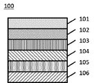
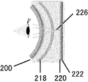
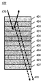
- FIG. 1 It is an example of a virtual reality display device using the optical laminate according to the first embodiment. It is an example of a virtual reality display device using the optical laminate according to the first embodiment. BRIEF DESCRIPTION OF THE DRAWINGS It is a schematic diagram which shows an example of the optical laminated body which concerns on 1st Embodiment. It is an example of a virtual reality display device using the optical laminate according to the second embodiment. It is an example of a virtual reality display device using the optical laminate according to the second embodiment. It is a schematic diagram which shows an example of the optical laminated body which concerns on 2nd Embodiment. It is a schematic diagram at the time of sticking the conventional optical laminated body to a lens. FIG.
- FIG. 10 is a schematic diagram for explaining the action of the optical layered body according to the second embodiment; It is a figure which shows notionally an example of the manufacturing method which concerns on 3rd Embodiment. It is a conceptual diagram for explaining an example of a manufacturing method according to a third embodiment. It is a schematic diagram which shows an example of a structure of the optical laminated body which concerns on 4th Embodiment. It is an example of a virtual reality display device using the optical laminate according to the fourth embodiment. It is an example of a virtual reality display device using a conventional reciprocating optical system. It is a schematic diagram which shows an example of a structure of the conventional optical laminated body.
- perpendicular does not mean exactly 90°, but 90° ⁇ 10°, preferably 90° ⁇ 5°.
- parallel does not strictly represent 0°, but represents 0° ⁇ 10°, preferably 0° ⁇ 5°.
- 45° does not mean exactly 45°, but 45° ⁇ 10°, preferably 45° ⁇ 5°.
- the "absorption axis” means the polarization direction in which the absorbance is maximized in the plane when linearly polarized light is incident.
- the “reflection axis” means the polarization direction in which the reflectance is maximized in the plane when linearly polarized light is incident.
- the “transmission axis” means a direction perpendicular to the absorption axis or the reflection axis in the plane.
- the “slow axis” means the direction in which the refractive index is maximized in the plane.
- the retardation means in-plane retardation and is described as Re( ⁇ ) unless otherwise specified.
- Re( ⁇ ) represents the in-plane retardation at the wavelength ⁇
- the wavelength ⁇ is 550 nm unless otherwise specified.
- the retardation in the thickness direction at the wavelength ⁇ is described as Rth( ⁇ ) in this specification.
- values measured at wavelength ⁇ using AxoScan OPMF-1 can be used.
- the optical laminate according to the first embodiment includes at least a reflective polarizer and an absorptive polarizer, and the absorptive polarizer has an anisotropic absorption layer containing at least a liquid crystalline compound and a dichroic dye.
- the number of foreign substances having a side length of 30 ⁇ m or more existing inside the optical layered body is 100 or less per square meter.
- the optical laminate according to the first embodiment can be used as a reflective-transmissive circular polarizer in a virtual reality display device, and has high image sharpness at that time.
- a reflective-transmissive circular polarizer in a virtual reality display device
- the optical laminate according to the first embodiment can be used as a reflective-transmissive circular polarizer in a virtual reality display device, and has high image sharpness at that time.
- FIG. 1 is a virtual reality display device using the optical laminate according to the first embodiment.
- light ray 160 emitted from image display panel 150 passes through circular polarizer 140 to become circularly polarized light, and passes through half mirror 130 .
- the light enters the optical laminate 100 according to the first embodiment from the reflective polarizer side, is totally reflected, is reflected again by the half mirror 130, and enters the optical laminate 100 again.
- the light ray 160 is reflected by the half-mirror, so that the light ray 160 is circularly polarized in a direction opposite to the circularly polarized light when it first entered the optical layered body 100 . Therefore, the light ray 160 passes through the optical stack 100 and is visible to the user.
- the half mirror 130 when the light ray 160 is reflected by the half mirror 130, the half mirror is shaped like a concave mirror, so that the image is magnified and the user can visually recognize the magnified virtual image.
- the mechanism described above is called a reciprocating optical system, a folding optical system, or the like.
- FIG. 2 is a schematic diagram showing a case where a light ray 170 that first enters the optical layered body 100 is transmitted without being reflected, resulting in leakage light.
- the user sees an unmagnified image.
- This image is called a ghost or the like, and is required to be reduced. ghosting is caused by part of the light emitted from the image display panel, which should be reflected by the reflective polarizer, being transmitted without being reflected.
- the optical layered body 100 since the optical layered body 100 according to the first embodiment includes the reflective polarizer and the absorptive polarizer, it has a high degree of polarization, and the polarized light that should be originally reflected by the reflective polarizer Even when the light passes through the reflective polarizer, the light can be absorbed by the absorptive polarizer to reduce the ghost.
- the number of foreign substances having a side length of 30 ⁇ m or more existing inside is 100 or less per square meter.
- a virtual reality display device using an optical laminate displays an enlarged image using a reciprocating optical system. reduce the intensity.
- the number of foreign substances embedded in the optical layered body is small, because the surface smoothness of the optical layered body can be improved.
- the optical laminated body used for the virtual reality display device is usually cut according to the size of the lens, and several hundred pieces per square meter can be cut out. Therefore, it is preferable that the number of foreign substances having a side length of 30 ⁇ m or more is 100 or less per square meter, because the yield when the lens is cut into the size of the lens can be improved.
- the number of foreign particles having a side length of 30 ⁇ m or more is preferably 50 or less per square meter, more preferably 10 or less, and even more preferably 5 or less. Although the lower limit is not particularly limited, 0 is included.
- a foreign matter is a portion (lump) that can be recognized as being optically different when the optical layered body is observed using an optical microscope.
- the foreign matter may be either organic matter or inorganic matter. Examples of foreign matter include dust, dust, foreign matter such as metal pieces, aggregates of additives, and synthetic defective components generated during the production of the optical layered body.
- the method for measuring foreign matter in the optical layered body is the number of foreign particles in the optical layered body observed per square meter when observed with an optical microscope (magnification: 100 times) from the normal direction of the surface of the optical layered body. to measure.
- the optical layered body of that area is used to observe with an optical microscope from the normal direction of the surface of the optical layered body to measure the number of foreign substances.
- the length of one side of the foreign matter means the long axis. More specifically, it refers to the largest line segment among the line segments connecting two points in the image of the observed foreign matter when observed with an optical microscope from the normal direction of the surface of the optical layered body.
- the optical layered body according to the first embodiment is preferably transparent to near-infrared light.
- the optical layered body according to the first embodiment includes at least an absorptive polarizer.
- the absorptive polarizer used in the optical layered body according to the first embodiment absorbs linearly polarized incident light along the absorption axis and transmits linearly polarized incident light along the transmission axis.
- the single plate transmittance of the absorbing polarizer is preferably 40% or more, more preferably 42% or more. Although the upper limit of the single plate transmittance is not particularly limited, it is often 50% or less, and more often 43% or less. Also, the degree of polarization is preferably 90% or more, more preferably 95% or more, and even more preferably 99% or more.
- the upper limit of the degree of polarization is not particularly limited, it may be 100%.
- the single plate transmittance and the degree of polarization of the absorption polarizer are measured using an automatic polarizing film measuring device: VAP-7070 (manufactured by JASCO Corporation). The above single-plate transmittance and degree of polarization are measured values at a wavelength of 550 nm.
- the absorptive polarizer used in the optical laminate according to the first embodiment has an anisotropic absorption layer containing at least a liquid crystalline compound and a dichroic dye.
- An anisotropic absorption layer containing a liquid crystalline compound and a dichroic dye is preferable because it can be made thin and is less susceptible to cracks, breakage, and the like even when stretched and/or molded.
- the thickness of the anisotropic absorption layer is not particularly limited, but is preferably 0.1 to 8 ⁇ m, more preferably 0.3 to 5 ⁇ m, from the viewpoint of thinning. Absorptive polarizers containing a liquid crystalline compound and a dichroic dye can be produced, for example, with reference to Japanese Unexamined Patent Application Publication No.
- the degree of orientation of the dichroic dye in the anisotropic absorbing layer is preferably 0.95 or more, more preferably 0.97 or more. .
- the upper limit is not particularly limited, 1.00 can be mentioned.
- liquid crystalline compound both a low-molecular-weight liquid crystalline compound and a high-molecular-weight liquid crystalline compound can be used.
- low-molecular-weight liquid crystalline compound refers to a liquid crystalline compound having no repeating unit in its chemical structure.
- polymeric liquid crystalline compound refers to a liquid crystalline compound having a repeating unit in its chemical structure.
- a dichroic dye means a dye that absorbs differently depending on the direction. The dichroic dye may or may not exhibit liquid crystallinity. When the dichroic dye exhibits liquid crystallinity, it may exhibit nematicity or smecticity.
- the anisotropic absorption layer preferably functions as a so-called linear polarizer that has the function of converting light into specific linearly polarized light.
- the guest-host type liquid crystal cell technology can be used to align the molecules of the dichroic dye in a desired orientation along with the orientation of the host liquid crystal. Specifically, a dichroic dye as a guest and a liquid crystalline compound as a host liquid crystal are mixed, the host liquid crystal is aligned, and the molecules of the dichroic dye are aligned along the alignment of the liquid crystal molecules.
- the anisotropic absorbing layer can be produced by fixing the orientation state of the film.
- Absorptive polarizers may include supports, alignment layers, protective layers, and the like.
- the orientation layer is used to orient the liquid crystalline compound contained in the anisotropic absorption layer in a specific direction.
- the alignment layer is not particularly limited, but a rubbed layer containing polyvinyl alcohol and a photo-alignment film can be used.
- the protective layer can be provided by coating on the anisotropic absorbing layer.
- the composition of the protective layer is not particularly limited, but a layer containing polyvinyl alcohol is preferable from the viewpoint of increasing the durability of the anisotropic absorbing layer.
- the type of support is not particularly limited, it is preferably transparent.
- Examples include cellulose acylate, polycarbonate, polysulfone, polyethersulfone, polyacrylate, polymethacrylate, cyclic polyolefin, polyolefin, polyamide, polystyrene, and polyester.
- film can be used. Among them, a cellulose acylate film, a cyclic polyolefin, a polyacrylate film, or a polymethacrylate film is preferable.
- commercially available cellulose acetate films for example, “TD80U” and “Z-TAC” manufactured by Fuji Film Co., Ltd.
- the support preferably has a small retardation from the viewpoint of suppressing adverse effects on the degree of polarization of transmitted light and reflected light.
- the magnitude of Re is preferably 10 nm or less
- the absolute value of the magnitude of Rth is preferably 50 nm or less.
- a transfer type film in which a layer including an anisotropic absorbing layer is coated on a temporary support may be used. More specifically, an absorptive polarizer including an anisotropic absorption layer is formed by transferring the anisotropic absorption layer in the transfer type film to another laminate and then peeling off and removing the temporary support. may By removing the temporary support, the thickness of the optical laminate can be reduced, and the adverse effect of the retardation of the temporary support on the degree of polarization of transmitted light and reflected light can be eliminated, which is preferable.
- the temporary support is preferably a support with high tear strength from the viewpoint of preventing breakage during peeling. For example, polycarbonate films or polyester films are preferred.
- the retardation of the temporary support is small in order to inspect the quality of the anisotropic absorbing layer and/or other layered body.
- the absorbing polarizer is supplied as a transfer type film in which a layer containing an anisotropic absorbing layer is coated on a temporary support, a slitting process or the like is carried out during transport of the film and before lamination.
- the protective film in the form of being laminated on the anisotropic absorption layer of the transfer type film.
- the optical laminate according to the first embodiment includes at least a reflective polarizer.
- a reflective polarizer There is no limitation on the reflective polarizer, and various known reflective polarizers can be used.
- a reflective polarizer is basically a reflective linear polarizer or a reflective circular polarizer.
- a reflective linear polarizer is a polarizer that transmits linearly polarized light in a certain direction and reflects linearly polarized light in a direction perpendicular to the linearly polarized light.
- a reflective linear polarizer a film obtained by stretching a dielectric multilayer film in which two or more different birefringent layers are alternately laminated, as described in JP-A-2011-053705.
- a wire grid polarizer, etc., as described in Japanese Patent Laid-Open No. 2015-028656 and the like are exemplified.
- Commercially available reflective linear polarizers are also suitable for use.
- Examples of commercially available reflective linear polarizers include a reflective polarizer (trade name: APF) manufactured by 3M and a wire grid polarizer (trade name: WGF) manufactured by AGC.
- the reflective linear polarizer is preferably a reflective linear polarizer in which at least two or more different birefringent layers are alternately laminated.
- a reflective circular polarizer is a polarizer that transmits right-handed circularly polarized light or left-handed circularly polarized light and reflects circularly polarized light whose direction of rotation is opposite to that of the transmitted circularly polarized light.
- a reflective circular polarizer having a cholesteric liquid crystal layer is exemplified.
- a cholesteric liquid crystal layer is a layer in which a cholesterically aligned liquid crystal phase (cholesteric liquid crystal phase) is fixed.
- a cholesteric liquid crystal layer has a helical structure in which a liquid crystalline compound is spirally revolved and stacked, and has a configuration in which the liquid crystalline compound is spirally stacked with one rotation (360° rotation). It has a structure in which a plurality of pitches of a liquid crystalline compound spirally swirling is laminated for one helical pitch (helical pitch).
- the cholesteric liquid crystal layer reflects right-handed circularly polarized light or left-handed circularly polarized light in a specific wavelength range, depending on the length of the helical pitch and the direction of helical rotation (sense) of the liquid crystalline compound, and rejects other light. To Penetrate.
- a reflective circular polarizer may include, for example, a cholesteric liquid crystal layer having a central wavelength for selective reflection to red light, a cholesteric liquid crystal layer having a central wavelength for selective reflection to green light, It may have a plurality of cholesteric liquid crystal layers, such as a cholesteric liquid crystal layer having a central wavelength and a cholesteric liquid crystal layer having a central wavelength for selective reflection to blue light.
- the optical laminate according to the first embodiment may include a ⁇ /4 retardation plate.
- a ⁇ /4 retardation plate refers to a retardation plate having an in-plane retardation (Re) of about 1/4 wavelength at any wavelength of visible light.
- the ⁇ /4 retardation plate has the effect of converting circularly polarized light into linearly polarized light and linearly polarized light into circularly polarized light. Therefore, the ⁇ / 4 retardation plate is laminated with an absorbing polarizer so that the orientation of the slow axis forms 45° with the orientation of the absorption axis of the absorbing polarizer, and used as an absorbing circular polarizing plate. can be done.
- It can also be used as a reflective circular polarizer by laminating it with a reflective polarizer so that the slow axis is at 45° to the transmission axis of the reflective polarizer. Furthermore, it can be laminated with a reflective circular polarizer at an arbitrary angle to be used as a reflective linear polarizer.
- a ⁇ /4 retardation plate having an Re of 120 to 150 nm at a wavelength of 550 nm is preferably exemplified, and a ⁇ /4 retardation plate having an Re of 130 to 140 nm is more preferably exemplified. be done.
- a retardation plate whose Re is about 3/4 wavelength or about 5/4 wavelength can also convert linearly polarized light into circularly polarized light, so it can be used in the same way as a ⁇ /4 retardation plate. can.
- the ⁇ /4 retardation plate used in the optical layered body according to the first embodiment preferably has reverse wavelength dispersion with respect to wavelength. Having reverse wavelength dispersion is preferable because circularly polarized light can be converted into linearly polarized light over a wide wavelength range in the visible region.
- having reverse wavelength dispersion with respect to wavelength means that the value of the phase difference at the wavelength increases as the wavelength increases.
- a retardation plate having reverse wavelength dispersion can be produced by uniaxially stretching a polymer film such as a modified polycarbonate resin film having reverse wavelength dispersion, for example, with reference to JP-A-2017-049574. can. Further, the retardation plate having reverse wavelength dispersion should have substantially reverse wavelength dispersion.
- the optical laminate according to the first embodiment may have a reflective circular polarizer, a quarter-wave retardation plate, a half-wave retardation plate, and a linear polarizer in this order. preferable.
- the retardation plate used in the optical laminate according to the first embodiment is a layer obtained by fixing a liquid crystalline compound (more preferably, a layer obtained by fixing a uniformly aligned liquid crystalline compound (liquid crystal phase)). It is also preferred to have For example, a layer in which a rod-like liquid crystalline compound is uniformly oriented horizontally to the in-plane direction, or a layer in which a discotic liquid crystalline compound is uniformly oriented perpendicular to the in-plane direction can be used. Furthermore, for example, referring to JP-A-2020-084070, etc., a retardation plate having reverse wavelength dispersion is produced by uniformly aligning and fixing a rod-like liquid crystalline compound having reverse wavelength dispersion. You can also
- the retardation plate used in the optical layered body according to the first embodiment preferably has a layer formed by fixing a liquid crystalline compound twisted with the thickness direction as the helical axis.
- a layer formed by fixing a rod-like liquid crystalline compound or a discotic liquid crystalline compound twisted with the thickness direction as a helical axis can be considered to have substantially reverse wavelength dispersion, which is preferable.
- the thickness of the ⁇ /4 retardation plate is not particularly limited, it is preferably 0.1 to 8 ⁇ m, more preferably 0.3 to 5 ⁇ m, from the viewpoint of thinning.
- the ⁇ /4 retardation plate according to the first embodiment may include a support, an orientation layer, a retardation plate, and the like.
- the type of support is not particularly limited, it is preferably transparent.
- examples include cellulose acylate, polycarbonate, polysulfone, polyethersulfone, polyacrylate, polymethacrylate, cyclic polyolefin, polyolefin, polyamide, polystyrene, and polyester. of film can be used. Among them, a cellulose acylate film, a cyclic polyolefin, a polyacrylate film, or a polymethacrylate film is preferable.
- the support preferably has a small retardation from the viewpoint of suppressing adverse effects on the degree of polarization of transmitted light and reflected light.
- the magnitude of Re is preferably 10 nm or less
- the absolute value of the magnitude of Rth is preferably 50 nm or less.
- the ⁇ /4 retardation plate is supplied as a transfer type film in which a layer containing a retardation layer is coated on a temporary support when producing an optical laminate, and the retardation layer is applied to another laminate. It may also be formed by peeling off the temporary support after transfer to the substrate. By removing the temporary support, the thickness of the optical laminate can be reduced, and the adverse effect of the retardation of the temporary support on the degree of polarization of transmitted light and reflected light can be eliminated, which is preferable.
- the temporary support is preferably a support having high tear strength from the viewpoint of preventing breakage during peeling. For example, a polycarbonate film or polyester film is preferred. Further, in the production process of the optical layered body, it is preferable that the retardation of the temporary support is small in order to inspect the quality of the anisotropic absorbing layer and/or other layered body.
- optical laminate according to the first embodiment may have other functional layers.
- the optical layered body according to the first embodiment further has a positive C plate.
- the positive C plate is a retardation layer in which Re is substantially zero and Rth has a negative value.
- a positive C plate can be obtained, for example, by vertically aligning a rod-like liquid crystalline compound.
- the positive C plate functions as an optical compensation layer for increasing the degree of polarization of transmitted light and reflected light with respect to obliquely incident light.
- the positive C-plate can be installed at any position in the optical laminate, and a plurality of positive C-plates may be installed.
- the positive C plate may be placed adjacent to the reflective circular polarizer or inside the reflective circular polarizer.
- the light reflecting layer has a positive Rth.
- the polarization states of the reflected light and the transmitted light change due to the action of Rth, and the degree of polarization of the reflected light and the transmitted light may decrease.
- Placing a positive C plate inside or near the reflective circular polarizer is preferable because it can suppress changes in the polarization state of obliquely incident light, and can suppress a decrease in the degree of polarization of reflected light and transmitted light.
- the positive C plate may be installed adjacent to the ⁇ /4 retardation plate or inside the ⁇ /4 retardation plate.
- the ⁇ /4 retardation plate has a positive Rth.
- the polarization state of the transmitted light may change due to the action of Rth, and the degree of polarization of the transmitted light may decrease.
- a positive C plate is arranged inside or near the ⁇ /4 retardation plate, it is possible to suppress a change in the polarization state of obliquely incident light and suppress a decrease in the degree of polarization of transmitted light, which is preferable.
- the positive C plate is preferably installed on the opposite side of the ⁇ / 4 retardation plate from the absorbing polarizer, but it is installed in other places. good too.
- Re of the positive C plate is preferably about 10 nm or less, and Rth is preferably -90 to -40 nm.
- the optical layered body according to the first embodiment has an antireflection layer on the surface.
- the optical layered body according to the first embodiment has a function of reflecting a specific circularly polarized light and transmitting circularly polarized light orthogonal thereto. , thereby reducing the degree of polarization of transmitted and reflected light. Therefore, the optical layered body preferably has an antireflection layer on its surface.
- the antireflection layer may be provided only on one surface of the optical laminate, or may be provided on both surfaces.
- the type of the antireflection layer is not particularly limited, a moth-eye film or an AR film is preferable from the viewpoint of lowering the reflectance.
- the optical layered body is stretched or molded
- a moth-eye film is preferable because high antireflection performance can be maintained even if the film thickness varies due to stretching.
- the antireflection layer contains a support and is stretched and/or molded
- the support has a tan ⁇ peak temperature of 170° C. or less from the viewpoint of facilitating stretching and/or molding. and more preferably 130° C. or less.
- a PMMA film or the like is preferable.
- the optical layered body according to the first embodiment further includes a second ⁇ /4 retardation plate.
- the optical laminate may include, for example, a reflective circular polarizer, a ⁇ /4 retardation plate, an absorptive polarizer, and a second ⁇ /4 retardation plate in that order.
- Light incident on the optical laminate from the reflective circular polarizer side and transmitted through the reflective circular polarizer, the ⁇ /4 retardation plate, and the absorptive polarizer is linearly polarized light. The portion is reflected by the outermost surface on the absorptive polarizer side and emitted again from the surface on the reflective circular polarizer side.
- Such light is unnecessary reflected light and can be a factor in lowering the degree of polarization of the reflected light, so it is preferable to reduce it. Therefore, there is a method of laminating an antireflection layer in order to suppress reflection on the outermost surface on the side of the absorbing polarizer. Even if the lamination surface of the laminate has an antireflection layer, the reflection on the surface of the medium cannot be suppressed, so the antireflection effect cannot be obtained. On the other hand, when a second ⁇ /4 retardation plate that converts linearly polarized light into circularly polarized light is installed, the light that reaches the outermost surface on the absorptive polarizer side becomes circularly polarized light and is reflected at the outermost surface of the medium.
- the second ⁇ /4 retardation plate preferably has substantially reverse wavelength dispersion.
- the optical laminate according to the first embodiment may further have a support.
- the support can be placed anywhere. Although the type of support is not particularly limited, it is preferably transparent. Examples include cellulose acylate, polycarbonate, polysulfone, polyethersulfone, polyacrylate, polymethacrylate, cyclic polyolefin, polyolefin, polyamide, polystyrene, and polyester. of film can be used. Among them, a cellulose acylate film, a cyclic polyolefin, a polyacrylate film, or a polymethacrylate film is preferable.
- the support preferably has a small retardation from the viewpoint of suppressing adverse effects on the degree of polarization of transmitted light and reflected light and from the viewpoint of facilitating optical inspection of the optical laminate.
- the magnitude of Re is preferably 10 nm or less
- the absolute value of the magnitude of Rth is preferably 50 nm or less.
- the support When the optical laminate according to the first embodiment is to be stretched and/or molded, the support preferably has a tan ⁇ peak temperature of 170°C or less. From the viewpoint of enabling molding at a low temperature, the peak temperature of tan ⁇ is more preferably 150° C. or lower, and even more preferably 130° C. or lower.
- a method for measuring tan ⁇ will be described.
- a dynamic viscoelasticity measuring device (“DVA-200" manufactured by IT Keisoku Co., Ltd.)
- Equipment DVA-200 manufactured by IT Instrumentation & Control Co., Ltd.
- Sample 5 mm, length 50 mm (gap 20 mm) Measurement conditions: Tensile mode Measurement temperature: -150°C to 220°C Temperature rising condition: 5°C/min Frequency: 1Hz Generally, in optical applications, a stretched resin substrate is often used, and the tan ⁇ peak temperature often becomes high due to the stretching treatment.
- a TAC (triacetylcellulose) substrate TG40, manufactured by Fujifilm Corporation
- TG40 triacetylcellulose
- resin substrates can be used for the support having a peak temperature of tan ⁇ of 170°C or less without particular limitation.
- Materials for the resin base include, for example, polyolefins such as polyethylene, polypropylene, and norbornene-based polymers; cyclic olefin-based resins; polyvinyl alcohol; polyethylene terephthalate; polymethacrylates and acrylic resins such as polyacrylates.
- cyclic olefin-based resins polyethylene terephthalate, or acrylic resins are preferable, and cyclic olefin-based resins or polymethacrylates are more preferable, because they are readily available on the market and have excellent transparency.
- resin substrates include Technoloy S001G, Technoloy S014G, Technoloy S000, Technoloy C001, Technoloy C000 (Sumika Acrylic Sales Co., Ltd.), Lumirror U type, Lumirror FX10, Lumirror SF20 (Toray Industries, Inc.), HK-53A ( Higashiyama Film Co., Ltd.), Teflex FT3 (Teijin DuPont Films Co., Ltd.), Escina, SCA40 (Sekisui Chemical Co., Ltd.), Zeonor Film (Optes Co., Ltd.), and Arton Film (JSR Corporation), etc. mentioned.
- the thickness of the support is not particularly limited, it is preferably 5 to 300 ⁇ m, more preferably 5 to 100 ⁇ m, even more preferably 5 to 30 ⁇ m.
- FIG. 3 is a schematic diagram showing an example of the configuration of the optical layered body according to the first embodiment.
- the optical layered body 100 shown in FIG. 2 ⁇ /4 retardation plates 106 .
- the optical layered body according to the first embodiment is a layered body composed of a large number of layers.
- Each layer can be adhered by any adhesion method, for example, a pressure sensitive adhesive or an adhesive can be used.
- a commercially available adhesive can be used arbitrarily, but it is preferably one that does not readily generate outgassing. In particular, when stretching and/or molding are performed, a vacuum process or a heating process may be performed, and it is preferable that outgassing does not occur even under these conditions.
- a commercially available adhesive or the like can be arbitrarily used, and for example, an epoxy resin-based adhesive or an acrylic resin-based adhesive can be used.
- the thickness of the pressure-sensitive adhesive and the adhesive layer is preferably 15 ⁇ m or less, more preferably 10 ⁇ m or less, from the viewpoint of improving the smoothness of the optical layered body and improving the sharpness of images in a virtual reality display device using the optical layered body. It is preferably 6 ⁇ m or less, more preferably 6 ⁇ m or less.
- the lower limit of the thickness of the adhesive layer is not particularly limited, but it is preferably 0.5 ⁇ m or more, more preferably 1 ⁇ m or more, from the viewpoint of burying foreign substances present inside the optical layered body and smoothing the thickness.
- the adhesive layer may have a thickness of 100 nm or less.
- the thickness of the adhesive layer is more preferably 50 nm or less.
- a method for forming an adhesive layer having a thickness of 100 nm or less for example, there is a method of vapor-depositing a ceramic adhesive such as silicon oxide (SiOx layer) on the surface of the target member.
- the surface of the target member may be subjected to surface modification treatment such as plasma treatment, corona treatment and saponification treatment before applying the adhesive.
- the adhesive may be applied after the primer layer is provided on the surface of the target member.
- the optical layered body has a plurality of adhesive layers, it is possible to adjust the type and thickness of the adhesive constituting the adhesive layer for each adhesive layer.
- an adhesive layer having a thickness of 100 nm or less can be provided by the procedures shown in (1) to (3) below.
- (1) One of two members laminated via an adhesive layer is attached to a temporary support made of a glass substrate.
- a SiOx layer is formed by vapor deposition on both the surface of the member bonded to the temporary support opposite to the temporary support and the exposed surface of the other member laminated via the adhesive layer. .
- each SiOx layer is appropriately adjusted so that the total thickness of the two SiOx layers is 100 nm or less, for example, the thickness of each SiOx layer is 50 nm or less.
- Vapor deposition can be performed using SiOx powder as a vapor deposition source, for example, using a vapor deposition apparatus (model ULEYES) manufactured by ULVAC, Inc., or the like.
- a vapor deposition apparatus model ULEYES
- the temporary support is peeled off from the one member. During lamination, it is preferable to bond the SiOx layers together by heating at a temperature of 120° C., for example.
- Each layer may be applied, adhered, or laminated by a roll-to-roll method or by a single wafer.
- the roll-to-roll method is preferable from the viewpoint of improving productivity and reducing misalignment of each layer.
- the single-wafer method is preferable because it is suitable for low-volume, high-mix production.
- methods for applying an adhesive to an adherend include roll coating, gravure printing, spin coating, wire bar coating, extrusion coating, direct gravure coating, reverse gravure coating, and die coating. well-known methods such as a method, a spray method, and an inkjet method.
- the adhesive layer can be eliminated by applying directly onto the adjacent layer that has already been formed. Furthermore, when one or both of the adjacent layers are layers containing a liquid crystalline compound, the alignment direction of the liquid crystalline compound changes continuously at the interface in order to reduce the refractive index difference in all in-plane directions.
- a linear polarizer containing a liquid crystalline compound and a dichroic substance is directly coated with a composition for forming a retardation layer containing a liquid crystalline compound, and the alignment control force of the liquid crystalline compound of the linear polarizer causes The alignment direction of the liquid crystalline compound in the retardation layer can be aligned so as to be continuous with the linear polarizer at the interface.
- One aspect of the method for manufacturing an optical layered body according to the first embodiment has a temporary support and an anisotropic absorbing layer disposed on the temporary support, and the anisotropic absorbing layer side of the temporary support Both ends of the film having regions where the anisotropic absorbing layer is not arranged at both ends in the width direction of the surface of are slit, and the anisotropic absorbing layer arranged on the entire surface of the temporary support and the temporary support and applying an adhesive or pressure-sensitive adhesive to the surface of the anisotropic absorption layer in the transfer type film opposite to the temporary support side to form a coating layer.
- Step 2A, Step 3A of obtaining a laminate by laminating a member containing a reflective polarizer on the coating layer, and Step 4A of producing an optical laminate by peeling the temporary support from the laminate. is preferred.
- the anisotropic absorbing layer is adhered to the base material up to the edge, and when the temporary support is peeled off, part of the anisotropic absorbing layer peels off and becomes a foreign substance. can be prevented.
- the member including the reflective polarizer may be composed of only the reflective polarizer, or may be configured to include the reflective polarizer and another member (eg, base material).
- Another aspect of the method for manufacturing an optical layered body according to the first embodiment has a temporary support and an anisotropic absorbing layer disposed on the temporary support, and the anisotropic absorbing layer side of the temporary support
- An adhesive or pressure-sensitive adhesive is applied to the surface of the anisotropic absorption layer of the transfer type film, which has areas where the anisotropic absorption layer is not arranged on both ends in the width direction of the surface of the transfer type film, on the side opposite to the temporary support side.
- step 1B of forming a coating layer step 2B of obtaining a laminate by bonding a member containing a reflective polarizer on the coating layer, and slitting both ends of the laminate to temporarily
- the anisotropic absorbing layer can be adhered to the substrate up to the end, and when the temporary support is peeled off, part of the anisotropic absorbing layer is peeled off and becomes a foreign substance. You can prevent it from being lost.
- the method for manufacturing the optical layered body according to the first embodiment described above includes a step of attaching an adhesive roll to the bonding surface of the anisotropic absorbing layer to remove foreign substances on the surface; to the base material in this order. As a result, foreign matter existing on the surface of the anisotropic absorption layer can be removed. More specifically, before step 1A or step 2A described above, a step of attaching an adhesive roll to the surface of the anisotropic absorbent layer opposite to the temporary support side to remove foreign matter on the surface is further added.
- the intention of the anisotropic absorbing layer is that the peeling force between the adhesive roll and the bonding surface of the anisotropic absorbing layer is lower than the peeling force between the anisotropic absorbing layer and the temporary support. It is preferable from the viewpoint of preventing undesired peeling.
- the optical layered body according to the first embodiment can be used by being incorporated in, for example, an in-vehicle rearview mirror, a virtual reality display device, an electronic viewfinder, an aerial image display device, and the like.
- the optical layered body according to the first embodiment is very useful from the viewpoint of improving the sharpness of a displayed image in a virtual reality display device, an electronic viewfinder, or the like having a reciprocating optical system.
- the optical layered body according to the second embodiment includes at least an absorptive polarizer, and at least a part of the end face is tapered.
- the entire circumference of the end surface of the optical layered body is tapered.
- the tapered end face means that the end face is inclined with respect to one main surface of the optical layered body when viewed in a cross section in the thickness direction of the optical layered body. and that one main surface of the optical laminate forms an angle of more than 90° with the end surface. In other words, it means that the angle formed by the end face and the normal to the main surface of the optical layered body is greater than 0° when viewed in a cross section in the thickness direction of the optical layered body.
- the optical layered body according to the second embodiment is easy to adjust the position and angle when attached to an adherend, and when used by being attached to a lens or the like of a virtual reality display device, a ghost occurs. and/or a decrease in contrast can be suppressed.
- a ghost occurs. and/or a decrease in contrast can be suppressed.
- the case where the optical layered body is used in a virtual reality display device will be taken up, and the action of the optical layered body according to the second embodiment will be described in detail.
- FIG. 4 shows a virtual reality display device using the optical layered body according to the second embodiment.
- the virtual reality display device shown in FIG. 4 includes an image display panel 222, a circular polarizer 220 arranged on the output surface side of the image display panel 222, a half mirror 218, and an optical laminate 200 according to the second embodiment. and have As shown in FIG. 4, the half mirror 218 has the shape of a concave mirror curved concavely toward the exit side of the virtual reality display device (the side opposite to the image display panel 222). Further, the optical layered body 200 has a concavely curved shape on the exit side of the virtual reality display device (the side opposite to the image display panel 222).
- FIG. 4 shows a virtual reality display device using the optical layered body according to the second embodiment.
- the virtual reality display device shown in FIG. 4 includes an image display panel 222, a circular polarizer 220 arranged on the output surface side of the image display panel 222, a half mirror 218, and an optical laminate 200 according to the second embodiment
- a space may be provided between the optical laminate 200 and the half mirror 218 and between the half mirror 218 and the circular polarizer 220, or, for example, a lens-like space may be provided.
- a substrate may be present, and each member may be bonded to this lens-shaped substrate.
- the optical laminate 200 used in such a virtual reality display device has at least an absorptive polarizer, a reflective polarizer, and a ⁇ /4 retardation plate.
- the optical laminate 200 includes a ⁇ /4 retardation plate, a reflective polarizer (a reflective linear polarizer), and an absorptive polarizer (absorptive linear polarizer) in this order from the image display panel 222 side. have.
- the transmission axis of the reflective polarizer and the transmission axis of the absorptive polarizer are arranged in parallel.
- the ⁇ /4 retardation plate is not limited to the configuration included in the optical layered body 200 , and the ⁇ /4 retardation plate may be provided separately from the optical layered body 200 .
- a light ray 224 for forming a virtual image emitted from an image display panel 222 is transmitted through a circular polarizer 220 to be circularly polarized, and then transmitted through a half mirror 218. .
- the circularly polarized light incident on the optical laminate 200 is converted into linearly polarized light by the ⁇ /4 retardation plate. Since the reflective polarizer is arranged so that the polarization direction of this linearly polarized light is parallel to the reflection axis of the reflective polarizer, it is totally reflected by the reflective polarizer and converted to circularly polarized light by the ⁇ /4 retardation plate. It is converted and advances to the half mirror 218 side.
- the light ray 224 is circularly polarized orthogonal to the circularly polarized light when it first enters the optical layered body 200 by being reflected by the half mirror. Therefore, the circularly polarized light incident on the optical laminate 200 is converted into linearly polarized light by the ⁇ /4 retardation plate. Since the polarization direction of the linearly polarized light at this time is orthogonal to the reflection axis of the reflective polarizer, it is transmitted through the reflective polarizer and the absorptive polarizer. Accordingly, light ray 224 is transmitted through optical stack 200 and viewed by the user.
- the image is magnified because the half mirror has the shape of a concave mirror, and the user can visually recognize the magnified virtual image.
- the curvature of the optical stack 200 may also magnify the image.
- the mechanism described above is called a reciprocating optical system, a folding optical system, or the like.
- FIG. 5 is a schematic diagram showing a case where a light ray 226 that first enters the optical layered body 200 is transmitted without being reflected, resulting in leakage light.
- the user sees an unmagnified image.
- This image is called a ghost or the like, and is required to be reduced.
- ghosting is caused by part of the light emitted from the image display panel, which should be reflected by the reflective polarizer, being transmitted without being reflected.
- One possible cause of such light leakage is that the optical laminate is not installed at an appropriate angle.
- An optical layered body is usually attached to the surface of a lens.
- the optical layered body is cut into a circle or the like according to the shape of the lens, it becomes difficult to adjust the angle and position when attaching to the lens. Angular misalignment is likely to occur.
- a lens lens-shaped substrate
- the optical layered body When laminating 200, angle deviation is likely to occur. If the angle shift occurs, the light rays incident on the optical layered body will not be in an appropriate polarization state, resulting in light leakage.
- the optical laminated body into a shape that includes a free curve instead of a circle, or to form a protrusion for alignment, etc.
- it is necessary to cut the optical laminate into a shape that includes a free curve with high precision. is difficult.
- burrs may occur on the end faces.
- an adhesive layer for bonding to a lens or the like is laminated on the surface of the optical layered body, the adhesive may protrude due to cutting.
- the optical layered body according to the second embodiment has tapered end faces, so that even if burrs and/or pressure-sensitive adhesive protrude, they hardly spread outside the designed shape.
- positional adjustment and/or angle adjustment are facilitated when affixed to a lens or the like.
- the optical layered body is bonded to another member, if the end face is not tapered like the conventional optical layered body, the edge of the surface of the optical layered body to be bonded becomes difficult to see. , positional and/or angular adjustments may be insufficiently accurate.
- the optical layered body is curved as shown in FIG.
- the edge of the main surface 290a of 290 on the side to be bonded to the lens 228 (intersection line between the main surface 290a and the side surface 290c) is covered with the main surface 290b of the optical laminate 290 on the side opposite to the lens 228. It becomes difficult to see.
- the optical layered body according to the second embodiment has a tapered end face, when the optical layered body is bonded to another member, the edge of the surface on the bonding side of the optical layered body is Since it is easily visible, positional and/or angular adjustments can be made with high accuracy.
- the optical layered body 200 when the object to be adhered has a curved surface (especially, a convexly curved object) such as a lens, even if the optical layered body is curved, the optical layered body can be formed as shown in FIG.
- the edge of the main surface (first surface) 200a of the optical layered body 200 on the side to be bonded to the lens 228 (the line of intersection between the first surface 200a and the side surface 200c) is the main surface of the optical laminate 200 opposite to the lens 228. Since it is not covered by the surface (second surface) 200b and can be visually recognized, position adjustment and/or angle adjustment can be easily performed with high accuracy.
- the optical layered body 200 preferably has a first surface 200a having a larger area than the opposing second surface 200b as a bonding surface.
- part of the light rays emitted from the image display panel enters from the end surface of the optical layered body bonded to the lens, and passes through the optical layered body or the inside of the lens.
- the light is guided and scattered, which may lead to a decrease in contrast.
- the optical layered body according to the second embodiment since the end face is tapered, the light beam incident from the end face is refracted and is less likely to be guided inside the optical layered body at an angle.
- the area of the first surface in contact with the lens of the optical layered body is larger than the area of the opposing second surface, it is possible to more effectively suppress the guiding of light rays incident from the end surface.
- the taper angle is the angle between the tapered end surface and the perpendicular to the main surface (first surface or second surface) of the optical layered body when viewed in a cross section in the thickness direction of the optical layered body. It is preferably 1° or more and less than 30°, more preferably 10° or more and less than 30°.
- the optical layered body according to the second embodiment is preferably applied when the outline includes a free-form curve when viewed from the direction perpendicular to the main surface.
- the optical layered body is provided with a marking indicating the orientation of the absorption axis of the absorption polarizer. This makes it easy to adjust the angle when bonding to a lens or the like of a virtual reality display device.
- the method of marking is not particularly limited, and may be written on the optical layered body with ink or the like, or may be a notch formed in the optical layered body. Marking can also be applied by scratching the surface using laser processing or the like.
- the optical layered body according to the second embodiment is preferably transparent to near-infrared light.
- FIG. 6 shows an example of the layer structure of the optical layered body according to the second embodiment.
- the optical layered body 200 shown in FIG. It has a retardation plate 212, an adhesive layer 214, and a separate film 216 in this order.
- the main surface on the side of the separate film 216 is the first surface having a larger area
- the main surface on the antireflection layer 202 side is the second surface having a smaller area than the first surface. and the end faces are tapered.
- the separate film 216 protects the adhesive layer 214 and is peeled off when the optical layered body 200 is attached to another member. That is, the optical layered body 200 has the pressure-sensitive adhesive layer 214 on the first surface side having a large area, and can be attached to another member by means of the pressure-sensitive adhesive layer 214 .
- Each component will be described below.
- the optical layered body according to the second embodiment includes at least an absorptive polarizer.
- the absorptive polarizer used in the optical layered body according to the second embodiment absorbs linearly polarized incident light along the absorption axis and transmits linearly polarized incident light along the transmission axis. That is, the absorptive polarizer is a linear absorptive polarizer.
- the single plate transmittance of the absorbing polarizer is preferably 40% or more, more preferably 42% or more. Also, the degree of polarization is preferably 90% or more, more preferably 95% or more, and even more preferably 99% or more. In this specification, the single-plate transmittance and the degree of polarization of the absorption polarizer are measured using an automatic polarizing film measuring device: VAP-7070 (manufactured by JASCO Corporation).
- the absorptive polarizer used in the optical laminate according to the second embodiment preferably has an anisotropic absorption layer containing at least a liquid crystalline compound and a dichroic dye.
- An anisotropic absorbing layer containing a liquid crystalline compound and a dichroic dye is preferable because it can be made thin and is less susceptible to cracks and breakage even after stretching and/or molding. More specific aspects of the liquid crystal compound and the dichroic dye are as described in the first embodiment.
- the thickness of the anisotropic absorption layer is not particularly limited, it is preferably 0.1 to 8 ⁇ m, more preferably 0.3 to 5 ⁇ m, from the viewpoint of thinning.
- Absorptive polarizers containing a liquid crystalline compound and a dichroic dye can be produced, for example, with reference to Japanese Unexamined Patent Application Publication No. 2020-023153.
- the degree of orientation of the dichroic dye in the anisotropic absorbing layer is preferably 0.95 or more, more preferably 0.97 or more. .
- Absorptive polarizers may include supports, alignment layers, protective layers, and the like.
- the orientation layer is used to orient the liquid crystalline compound contained in the anisotropic absorption layer in a specific direction.
- the alignment layer is not particularly limited, but a rubbed layer containing polyvinyl alcohol, a photo-alignment film, or the like can be used.
- the protective layer can be provided by coating on the anisotropic absorbing layer.
- the composition of the protective layer is not particularly limited, but a layer containing polyvinyl alcohol is preferable from the viewpoint of increasing the durability of the anisotropic absorbing layer.
- the type of support is not particularly limited, it is preferably transparent.
- cellulose acylate examples include cellulose acylate, polycarbonate, polysulfone, polyethersulfone, polyacrylate, polymethacrylate, cyclic polyolefin, polyolefin, polyamide, polystyrene, and polyester.
- film can be used. Among them, cellulose acylate film, cyclic polyolefin, polyacrylate, and polymethacrylate are preferred.
- commercially available cellulose acetate films for example, “TD80U” and “Z-TAC” manufactured by Fuji Film Co., Ltd.
- the support preferably has a small retardation from the viewpoint of suppressing adverse effects on the degree of polarization of transmitted light and reflected light.
- the magnitude of Re is preferably 10 nm or less
- the absolute value of the magnitude of Rth is preferably 50 nm or less.
- an absorptive polarizer when manufacturing an absorptive polarizer, it may be supplied as a transfer film in which a layer including an anisotropic absorptive layer is coated on a temporary support. More specifically, it may be formed by transferring the anisotropic absorbing layer in the transfer type film to another laminate, and then peeling and removing the temporary support. By removing the temporary support, the thickness of the optical laminate can be reduced, and the adverse effect of the retardation of the temporary support on the degree of polarization of transmitted light and reflected light can be eliminated, which is preferable.
- the temporary support is preferably a support having high tear strength from the viewpoint of preventing breakage during peeling. For example, a polycarbonate film or polyester film is preferred.
- the retardation of the temporary support is small in order to inspect the quality of the anisotropic absorbing layer and/or other layered body.
- the absorbing polarizer is supplied as a transfer type film in which a layer containing an anisotropic absorbing layer is coated on a temporary support, a slitting process or the like is carried out during transport of the film and before lamination.
- the protective film in the form of being laminated on the anisotropic absorption layer of the transfer type film.
- the optical laminate according to the second embodiment may contain a reflective polarizer.
- a reflective polarizer There is no limitation on the reflective polarizer, and various known reflective polarizers can be used.
- a reflective polarizer is basically a reflective linear polarizer or a reflective circular polarizer.
- a reflective linear polarizer is a polarizer that transmits linearly polarized light in a certain direction and reflects linearly polarized light in a direction perpendicular to the linearly polarized light.
- a reflective linear polarizer a film obtained by stretching a dielectric multilayer film in which two or more different birefringent layers are alternately laminated, as described in JP-A-2011-053705.
- Wire-grid polarizers and the like as described in JP-A-2015-028656 and the like are exemplified.
- Commercially available reflective linear polarizers are also suitable for use. Examples of commercially available reflective linear polarizers include a reflective polarizer (trade name: APF) manufactured by 3M and a wire grid polarizer (trade name: WGF) manufactured by AGC.
- a reflective circular polarizer is a polarizer that transmits right-handed circularly polarized light or left-handed circularly polarized light and reflects circularly polarized light whose rotation direction is opposite to that of the transmitted circularly polarized light.
- a reflective circular polarizer having a cholesteric liquid crystal layer is exemplified.
- a cholesteric liquid crystal layer is a liquid crystal phase obtained by fixing a cholesterically aligned liquid crystal phase (cholesteric liquid crystal phase).
- a cholesteric liquid crystal layer has a helical structure in which a liquid crystalline compound is spirally revolved and stacked, and has a configuration in which the liquid crystalline compound is spirally stacked with one rotation (360° rotation). It has a structure in which a plurality of pitches of a liquid crystalline compound spirally swirling is laminated for one helical pitch (helical pitch).
- the cholesteric liquid crystal layer reflects right-handed circularly polarized light or left-handed circularly polarized light in a specific wavelength range, depending on the length of the helical pitch and the direction of helical rotation (sense) of the liquid crystalline compound, and rejects other light. To Penetrate.
- a reflective circular polarizer may include, for example, a cholesteric liquid crystal layer having a central wavelength for selective reflection to red light, a cholesteric liquid crystal layer having a central wavelength for selective reflection to green light, It may have a plurality of cholesteric liquid crystal layers, such as a cholesteric liquid crystal layer having a central wavelength and a cholesteric liquid crystal layer having a central wavelength for selective reflection to blue light.
- the optical laminate according to the second embodiment may contain a ⁇ /4 retardation plate.
- a ⁇ /4 retardation plate refers to a retardation plate having an in-plane retardation (Re) of about 1/4 wavelength at any wavelength of visible light.
- the ⁇ /4 retardation plate has the effect of converting circularly polarized light into linearly polarized light and linearly polarized light into circularly polarized light. Therefore, the ⁇ / 4 retardation plate is laminated with an absorbing polarizer so that the orientation of the slow axis forms 45° with the orientation of the absorption axis of the absorbing polarizer, and used as an absorbing circular polarizing plate. can be done.
- It can also be used as a reflective circular polarizer by laminating it with a reflective polarizer so that the slow axis is at 45° to the transmission axis of the reflective polarizer. Furthermore, it can be laminated with a reflective circular polarizer at an arbitrary angle to be used as a reflective linear polarizer.
- a ⁇ / 4 retardation plate having Re of 120 nm to 150 nm is preferably exemplified, and a ⁇ / 4 retardation plate having Re of 130 nm to 140 nm is more preferably exemplified.
- a retardation plate whose Re is about 3/4 wavelength or about 5/4 wavelength can also convert linearly polarized light into circularly polarized light, so it can be used in the same way as a ⁇ /4 retardation plate. can.
- the ⁇ /4 retardation plate used in the optical laminate according to the second embodiment preferably has reverse wavelength dispersion with respect to wavelength. Having reverse wavelength dispersion is preferable because circularly polarized light can be converted into linearly polarized light over a wide wavelength range in the visible region.
- having reverse wavelength dispersion with respect to wavelength means that the value of the phase difference at the wavelength increases as the wavelength increases.
- a retardation plate having reverse wavelength dispersion can be produced by uniaxially stretching a polymer film such as a modified polycarbonate resin film having reverse wavelength dispersion, for example, with reference to JP-A-2017-049574. can. Further, the retardation plate having reverse wavelength dispersion should have substantially reverse wavelength dispersion.
- the optical laminate according to the second embodiment may have a reflective circular polarizer, a quarter-wave retardation plate, a half-wave retardation plate, and a linear polarizer in this order. preferable.
- the retardation plate used in the optical laminate according to the second embodiment is a layer formed by fixing a liquid crystalline compound (more preferably, a layer formed by fixing a uniformly aligned liquid crystalline compound (liquid crystal phase)). It is also preferred to have For example, a layer in which a rod-like liquid crystalline compound is uniformly oriented horizontally to the in-plane direction, or a layer in which a discotic liquid crystalline compound is uniformly oriented perpendicular to the in-plane direction can be used. Furthermore, for example, referring to JP-A-2020-084070, etc., a retardation plate having reverse wavelength dispersion is produced by uniformly aligning and fixing a rod-like liquid crystalline compound having reverse wavelength dispersion. You can also
- the retardation plate used in the optical layered body according to the second embodiment preferably has a layer formed by fixing a liquid crystalline compound twisted with the thickness direction as the helical axis.
- a layer formed by fixing a rod-like liquid crystalline compound or a discotic liquid crystalline compound twisted with the thickness direction as a helical axis can be considered to have substantially reverse wavelength dispersion, which is preferable.
- the thickness of the ⁇ /4 retardation plate is not particularly limited, it is preferably 0.1 to 8 ⁇ m, more preferably 0.3 to 5 ⁇ m, from the viewpoint of thinning.
- the ⁇ /4 retardation plate according to the second embodiment may include a support, an orientation layer, a retardation plate, and the like.
- the type of support is not particularly limited, it is preferably transparent, and examples thereof include films of cellulose acylate, polycarbonate, polysulfone, polyethersulfone, polyacrylate and polymethacrylate, cyclic polyolefin, polyolefin, polyamide, polystyrene, polyester, and the like. can be used. Among them, cellulose acylate film, cyclic polyolefin, polyacrylate, and polymethacrylate are preferred.
- the support preferably has a small retardation from the viewpoint of suppressing adverse effects on the degree of polarization of transmitted light and reflected light.
- the magnitude of Re is preferably 10 nm or less
- the absolute value of the magnitude of Rth is preferably 50 nm or less.
- the ⁇ /4 retardation plate is supplied as a transfer type film in which a layer containing a retardation layer is coated on a temporary support when producing an optical laminate, and the retardation layer is applied to another laminate. It may be formed by peeling and removing the temporary support after transfer to the substrate. By removing the temporary support, the thickness of the optical laminate can be reduced, and the adverse effect of the retardation of the temporary support on the degree of polarization of transmitted light and reflected light can be eliminated, which is preferable.
- the temporary support is preferably a support with high tear strength from the viewpoint of preventing breakage during peeling. For example, polycarbonate films or polyester films are preferred. Further, in the production process of the optical layered body, it is preferable that the retardation of the temporary support is small in order to inspect the quality of the anisotropic absorbing layer and/or other layered body.
- optical laminate according to the second embodiment may have other functional layers.
- the optical layered body according to the second embodiment further has a positive C plate.
- the positive C plate is a retardation layer in which Re is substantially zero and Rth has a negative value.
- a positive C plate can be obtained, for example, by vertically aligning a rod-like liquid crystalline compound.
- the positive C plate functions as an optical compensation layer for increasing the degree of polarization of transmitted light and reflected light with respect to obliquely incident light.
- the positive C-plate can be installed at any position in the optical laminate, and a plurality of positive C-plates may be installed.
- the positive C plate may be placed adjacent to the reflective circular polarizer or inside the reflective circular polarizer.
- the light reflecting layer has a positive Rth.
- the polarization states of the reflected light and the transmitted light change due to the action of Rth, and the degree of polarization of the reflected light and the transmitted light may decrease.
- Placing a positive C plate inside or near the reflective circular polarizer is preferable because it can suppress changes in the polarization state of obliquely incident light, and can suppress a decrease in the degree of polarization of reflected light and transmitted light.
- the positive C plate may be installed adjacent to the ⁇ /4 retardation plate or inside the ⁇ /4 retardation plate.
- the ⁇ /4 retardation plate has a positive Rth.
- the polarization state of the transmitted light may change due to the action of Rth, and the degree of polarization of the transmitted light may decrease.
- a positive C plate is arranged inside or near the ⁇ /4 retardation plate, it is possible to suppress a change in the polarization state of obliquely incident light and suppress a decrease in the degree of polarization of transmitted light, which is preferable.
- the positive C plate is preferably installed on the opposite side of the ⁇ / 4 retardation plate from the absorbing polarizer, but it is installed in other places. good too.
- Re of the positive C plate is preferably about 10 nm or less, and Rth is preferably -90 to -40 nm.
- the optical layered body according to the second embodiment has an antireflection layer on the surface.
- the optical layered body according to the second embodiment has a function of reflecting a specific circularly polarized light and transmitting circularly polarized light orthogonal thereto. , thereby reducing the degree of polarization of transmitted and reflected light. Therefore, the optical layered body preferably has an antireflection layer on its surface.
- the antireflection layer may be provided only on one surface of the optical laminate, or may be provided on both surfaces.
- the type of the antireflection layer is not particularly limited, a moth-eye film or an AR film is preferable from the viewpoint of lowering the reflectance.
- the optical layered body is stretched or molded
- a moth-eye film is preferable because high antireflection performance can be maintained even if the film thickness varies due to stretching.
- the antireflection layer contains a support and is stretched and/or molded
- the support has a tan ⁇ peak temperature of 170° C. or less from the viewpoint of facilitating stretching and/or molding. and more preferably 130° C. or less.
- a PMMA film or the like is preferable.
- the optical layered body according to the second embodiment further includes a second ⁇ /4 retardation plate.
- the optical laminate may include, for example, a reflective circular polarizer, a ⁇ /4 retardation plate, an absorptive polarizer, and a second ⁇ /4 retardation plate in that order.
- Light incident on the optical laminate from the reflective circular polarizer side and transmitted through the reflective circular polarizer, the ⁇ /4 retardation plate, and the absorptive polarizer is linearly polarized light. The portion is reflected by the outermost surface on the absorptive polarizer side and emitted again from the surface on the reflective circular polarizer side.
- Such light is unnecessary reflected light and can be a factor in lowering the degree of polarization of the reflected light, so it is preferable to reduce it. Therefore, there is a method of laminating an antireflection layer in order to suppress reflection on the outermost surface on the side of the absorbing polarizer. Even if the lamination surface of the laminate has an antireflection layer, the reflection on the surface of the medium cannot be suppressed, so the antireflection effect cannot be obtained. On the other hand, when a second ⁇ /4 retardation plate that converts linearly polarized light into circularly polarized light is installed, the light that reaches the outermost surface on the absorptive polarizer side becomes circularly polarized light and is reflected at the outermost surface of the medium.
- the second ⁇ /4 retardation plate preferably has substantially reverse wavelength dispersion.
- the optical laminate according to the second embodiment may further have a support.
- the support can be placed anywhere. Although the type of support is not particularly limited, it is preferably transparent. Examples include cellulose acylate, polycarbonate, polysulfone, polyethersulfone, polyacrylate, polymethacrylate, cyclic polyolefin, polyolefin, polyamide, polystyrene, and polyester. of film can be used. Among them, a cellulose acylate film, a cyclic polyolefin, a polyacrylate film, or a polymethacrylate film is preferable.
- the support preferably has a small retardation from the viewpoint of suppressing adverse effects on the degree of polarization of transmitted light and reflected light and from the viewpoint of facilitating optical inspection of the optical laminate.
- the magnitude of Re is preferably 10 nm or less
- the absolute value of the magnitude of Rth is preferably 50 nm or less.
- the support When the optical laminate according to the second embodiment is to be stretched and/or molded, the support preferably has a tan ⁇ peak temperature of 170°C or less. From the viewpoint of enabling molding at a low temperature, the peak temperature of tan ⁇ is more preferably 150° C. or lower, and even more preferably 130° C. or lower.
- a method for measuring tan ⁇ will be described.
- a dynamic viscoelasticity measuring device (“DVA-200” manufactured by IT Keisoku Co., Ltd.)
- Equipment DVA-200 manufactured by IT Instrumentation & Control Co., Ltd.
- resin substrates can be used for the support having a peak temperature of tan ⁇ of 170°C or less without particular limitation.
- Materials for the resin base include, for example, polyolefins such as polyethylene, polypropylene, and norbornene-based polymers; cyclic olefin-based resins; polyvinyl alcohol; polyethylene terephthalate; polymethacrylates and acrylic resins such as polyacrylates.
- cyclic olefin-based resins polyethylene terephthalate, or acrylic resins are preferable, and cyclic olefin-based resins or polymethacrylates are more preferable, because they are readily available on the market and have excellent transparency.
- resin substrates include Technoloy S001G, Technoloy S014G, Technoloy S000, Technoloy C001, Technoloy C000 (Sumika Acrylic Sales Co., Ltd.), Lumirror U type, Lumirror FX10, Lumirror SF20 (Toray Industries, Inc.), HK-53A ( Higashiyama Film Co., Ltd.), Teflex FT3 (Teijin DuPont Films Co., Ltd.), Escina, SCA40 (Sekisui Chemical Co., Ltd.), Zeonor Film (Optes Co., Ltd.), and Arton Film (JSR Corporation), etc. mentioned.
- the thickness of the support is not particularly limited, it is preferably 5 to 300 ⁇ m, more preferably 5 to 100 ⁇ m, even more preferably 5 to 30 ⁇ m.
- the optical layered body according to the second embodiment may have a pressure-sensitive adhesive layer laminated on one of its surfaces for bonding to an adherend such as a lens.
- the adhesive a commercially available adhesive can be arbitrarily used, but from the viewpoint of improving the smoothness after bonding to a lens or the like, the thickness of the adhesive layer is preferably 25 ⁇ m or less, more preferably 15 ⁇ m or less. It is preferably 6 ⁇ m or less, more preferably 6 ⁇ m or less.
- the pressure-sensitive adhesive layer is preferably laminated on the first surface side.
- the optical layered body according to the second embodiment is a layered body composed of a large number of layers.
- Each layer can be adhered by any adhesion method, for example, adhesives and/or adhesives can be used.
- the adhesive any commercially available adhesive can be used, but it is preferable that the adhesive hardly generate outgassing. In particular, when stretching and/or molding are performed, a vacuum process and/or a heating process may be performed, and it is preferable that outgassing does not occur even under these conditions.
- a commercially available adhesive or the like can be arbitrarily used, and for example, an epoxy resin-based adhesive, an acrylic resin-based adhesive, or the like can be used.
- the thickness of the pressure-sensitive adhesive and the adhesive layer is preferably 15 ⁇ m or less, more preferably 10 ⁇ m or less, from the viewpoint of improving the smoothness of the optical layered body and improving the sharpness of images in a virtual reality display device using the optical layered body. , 6 ⁇ m or less.
- the lower limit of the thickness of the adhesive layer is not particularly limited, but it is preferably 0.5 ⁇ m or more, more preferably 1 ⁇ m or more, from the viewpoint of burying foreign matter present inside the optical layered body and smoothing it.
- the optical layered body according to the second embodiment can be cut into various shapes depending on the purpose.
- the method for cutting the optical layered body is not particularly limited, and various methods can be used.
- cutting using a short pulse laser is preferable.
- Short pulse lasers are lasers with very short pulse widths, such as nanoseconds, picoseconds, or femtoseconds. Cutting using a short-pulse laser is less likely to cause thermal damage to the cut end face of the optical layered body, and enables highly accurate cutting. Also, by adjusting the irradiation direction of the short-pulse laser, it is possible to make the cut end face tapered.
- the wavelength of the short pulse laser is not limited, for example, an ultraviolet laser, a green laser, an infrared laser, or the like can be used. Ultraviolet lasers are preferred because they are less likely to cause thermal damage.
- the short-pulse laser is preferably scanned using a galvanomirror. By using a galvanomirror, the optical layered body can be cut with high precision even if it has a complicated shape including a free-form curve. It is also preferable to combine the drive of the optical layered body by the XY stage and the drive of the short pulse laser by the galvanomirror.
- the optical layered body according to the second embodiment can also be cut by punching with a Thomson blade or engraving blade.
- the Thomson blade or engraving blade preferably has a tapered shape because the end surface of the optical layered body can be tapered.
- the optical layered body according to the second embodiment can be used by being incorporated in, for example, an in-vehicle rearview mirror, a virtual reality display device, an electronic viewfinder, an aerial image display device, and the like.
- the optical layered body according to the second embodiment is very useful in virtual reality display devices and electronic viewfinders having a reciprocating optical system from the viewpoint of suppressing the generation of ghosts and/or reduction in contrast.
- the method for producing an optical laminate according to the third embodiment uses a transfer type film in which a functional layer is formed on a temporary support by coating, for example, and a base film. An optical laminate is produced by transferring the functional layer of the film to the substrate film. Therefore, the optical laminate produced by the production method according to the third embodiment includes at least the base film and the functional layer.
- a functional layer is a layer for imparting an optical function or a physical function to the optical laminate.
- the functional layer include a polarizer layer, a retardation layer, an antireflection layer, an antistatic layer, a conductive layer, an adhesive layer (adhesive layer), and an adhesive layer (adhesive layer). , but not limited to.
- at least one functional layer is supplied as a transfer type film in which the functional layer is formed on the temporary support by coating, for example. This enables the functional layer to be transferred to the base film by peeling off the temporary support after bonding the functional layer to the base film. Also, by removing the temporary support, the thickness of the optical layered body can be reduced. Furthermore, when the optical layered body deals with polarized light, it is possible to eliminate the adverse effect of the retardation of the temporary support on the degree of polarization of transmitted light and reflected light.
- a polarizer layer as a functional layer includes, for example, an absorption polarizer.
- the absorptive polarizer absorbs linearly polarized light in the direction of the absorption axis and transmits linearly polarized light in the direction of the transmission axis out of incident light.
- the single plate transmittance of the absorbing polarizer is preferably 40% or more, more preferably 42% or more.
- the degree of polarization is preferably 90% or more, more preferably 95% or more, and even more preferably 99% or more.
- the single-plate transmittance and the degree of polarization of the absorbing polarizer are measured using an automatic polarizing film measuring device: VAP-7070 (manufactured by JASCO Corporation).
- the absorbing polarizer used in the manufacturing method according to the third embodiment preferably has an anisotropic absorbing layer containing at least a liquid crystalline compound and a dichroic dye. More specific aspects of the liquid crystal compound and the dichroic dye are as described in the first embodiment.
- the anisotropic absorption layer containing a liquid crystalline compound and a dichroic dye can be made thin, and by forming it on a temporary support by coating, it becomes a functional layer that can be transferred. is preferred because it is easy to
- the thickness of the anisotropic absorption layer is not particularly limited, but is preferably 0.1 to 8 ⁇ m, more preferably 0.3 to 5 ⁇ m, from the viewpoint of thinning.
- An absorptive polarizer containing a liquid crystalline compound and a dichroic dye can be produced, for example, with reference to JP-A-2020-023153.
- the degree of orientation of the dichroic dye in the anisotropic absorbing layer is preferably 0.95 or more, more preferably 0.97 or more. .
- the absorptive polarizer used in the manufacturing method according to the third embodiment may include an alignment layer, a protective layer, and the like.
- the orientation layer is used to orient the liquid crystalline compound contained in the anisotropic absorption layer in a specific direction.
- the alignment layer is not particularly limited, but a rubbed layer containing polyvinyl alcohol, a photo-alignment film, or the like can be used.
- the protective layer can be provided by coating on the anisotropic absorbing layer.
- the protective layer is not particularly limited, but a layer containing polyvinyl alcohol is preferable from the viewpoint of enhancing the durability of the anisotropic absorbent layer.
- Temporal support Such a functional layer is formed on the temporary support by, for example, coating.
- a transfer type film having a functional layer formed on a temporary support is used, and the functional layer is transferred from this transfer type film to a base film described later. to produce an optical laminate.
- the temporary support preferably has high tear strength from the viewpoint of preventing breakage during peeling.
- Preferred examples of such a temporary support include polycarbonate films and polyester films.
- the temporary support in order to inspect the quality of the anisotropic absorbing layer and other laminates in the manufacturing process of the optical laminate, the temporary support preferably has a small retardation.
- Materials constituting such a temporary support include, for example, cellulose acylate, cyclic polyolefin, polyacrylate, and polymethacrylate.
- the base film is a film to which the functional layer is transferred.
- the base film may have no optical function or physical function, or may have at least one of optical function and physical function.
- As the substrate film having at least one of optical function and physical function for example, a polarizer, a retardation plate, an antireflection film, an antistatic film, a conductive film, and the like can be used.
- a polarizer, a retardation plate, an antireflection film, an antistatic film, a conductive film, and the like can be used.
- another A transfer type film having a functional layer may be laminated. In this case, a laminate obtained by laminating several functional layers can be regarded as a base film in the present invention.
- the base film may be a retardation plate (retardation layer). Further, the base film may contain a retardation layer.
- the retardation layer can change the polarization state of incident light.
- the retardation layer preferably has reverse wavelength dispersion with respect to wavelength.
- having reverse wavelength dispersion with respect to wavelength means that the value of the phase difference at the wavelength increases as the wavelength increases.
- Retardation layer having reverse wavelength dispersion for example, with reference to JP-A-2017-049574, etc., can be produced by uniaxially stretching a polymer film such as a modified polycarbonate resin film having reverse wavelength dispersion. can.
- the retardation layer is produced by stretching the polymer film, it is preferable from the viewpoint of productivity to stretch the film in the transport direction or in a direction orthogonal to the transport direction. At this time, the azimuth of the slow axis of the retardation layer is parallel or perpendicular to the transport direction of the film. In the production method according to the third embodiment, these retardation layers can also be suitably used as the base film.
- the substrate film may be a polarizer, particularly a reflective linear polarizer.
- the base film may contain a reflective linear polarizer.
- a reflective linear polarizer is a polarizer that transmits linearly polarized light in a certain direction and reflects linearly polarized light in a direction perpendicular to the linearly polarized light.
- a reflective linear polarizer a film obtained by stretching a dielectric multilayer film in which two or more different birefringent layers are alternately laminated, as described in JP-A-2011-053705.
- wire grid polarizers and the like as described in Japanese Patent Laid-Open No.
- APF reflective polarizer
- WGF wire grid polarizer
- a reflective linear polarizer produced by stretching a dielectric multilayer film in which a plurality of two or more birefringent layers are alternately laminated is produced by stretching in a direction perpendicular to the transport direction of the film. It is preferable from the viewpoint of productivity. At this time, the transmission axis is parallel to the transport direction of the film, but in the production method according to the third embodiment, these reflective linear polarizers can also be suitably used as the base film.
- the production method includes a step of conveying a transfer type film in which a functional layer is coated on a temporary support and a base film, crossing each other at an angle that is not parallel to each other, and a step of conveying the functional layer A step of applying an adhesive or pressure-sensitive adhesive to the surface opposite to the temporary support side or the surface of the base film, and a step of temporarily stopping the transfer type film and the base film and attaching them to each other. and a step of peeling off the functional layer from the temporary support.
- a commercially available adhesive can be used arbitrarily, but it is preferably one that does not readily generate outgassing.
- the optical layered body when it is subjected to stretching, molding, and the like, it may undergo a vacuum process, a heating process, and the like, and it is preferable that outgassing does not occur even under these conditions.
- a commercially available adhesive or the like can be arbitrarily used as the adhesive. Examples include epoxy resin adhesives and acrylic resin adhesives.
- a manufacturing method according to the third embodiment will be described in detail with reference to the drawings. 9 and 10 schematically show an example of the manufacturing method according to the third embodiment.
- the transfer type film 300 in which the functional layer 304 is applied to the temporary support 306 and the base film 320 are transported in directions that are not parallel to each other.
- the transfer film 300 and the base film 320 are transported so as to cross each other.
- the conveying direction C1 of the transfer type film 300 and the conveying direction C2 of the base film 320 are orthogonal to each other in order to clarify the description of the manufacturing method according to the third embodiment.
- the transfer The optical axis 302 of the functional layer 304 of the mold film 300 and the optical axis 322 of the base film 320 can be crossed at any angle.
- the optical axis 302 of the functional layer 304 of the transfer type film 300 coincides with the longitudinal direction of the transfer type film 300, for example.
- the optical axis 322 of the base film 320 also coincides with the longitudinal direction of the base film 320 as an example.
- the angle formed by the conveying direction C1 of the transfer type film 300 and the conveying direction C2 of the base film 320 is the optical axis 302 of the functional layer 304 of the transfer type film 300 and the base film 320. and the optical axis 322 of .
- axis that exhibits an optical effect in an optical element (optical member), such as a slow axis, a fast axis, an absorption axis, a transmission axis, and a reflection axis. These objects are collectively called “optical axis”.
- Adhesive is applied by the coating unit 340 to the surface of the transported base film 320 to form an adhesive layer 330 .
- the adhesive layer 330 is formed on the surface of the side facing the transfer type film 300 later.
- the formation of the adhesive layer 330 is not limited to the surface of the base film 320, but the surface of the functional layer 304, that is, the application of the adhesive. It may be the surface of the layer 304 opposite to the temporary support 306 side.
- the first stage of FIG. 10 shows a state in which the functional layer 304 is transferred to the base film 320 by the manufacturing method according to the third embodiment, that is, the optical laminate is manufactured by the manufacturing method according to the third embodiment. It shows the state immediately after In the description of FIG. 10, the first stage, second stage, . In this state, the base film 320 to which the functional layer 304 has been transferred and the transfer type film 300 are separated. From this state, the transfer mold film 300 and the base film 320 are conveyed while keeping the base film 320 and the transfer mold film 300 apart, and as shown in the second stage of FIG. The transportation of the film 300 and the base film 320 is temporarily stopped. In the example shown in FIG.
- the transport direction C1 of the transfer type film 300 is the left direction in the drawing
- the transport direction C2 of the base film 320 is the depth direction perpendicular to the plane of the drawing.
- the functional layer 304 previously transferred to the base film 320 is located on the far side of the paper as indicated by the dashed line in the second row of FIG.
- the adhesive is applied to the surface of the base film 320 to form the adhesive layer 330 during this transport.
- the functional layer 304 and the base film 320 are bonded together.
- a step of pressing a roller against the bonded portion may be performed.
- the length of the roller 346 is not limited, but it is preferably the same length as the width of the transfer type film 300 .
- the entire surface of the laminated portion of the functional layer 304 and the base film 320 can be pressed, and the adhesion of the adhesive layer 330 to the roller 346 can be prevented. Further, if necessary, a step of curing the adhesive layer 330 (adhesive) by irradiating the bonded portion with ultraviolet rays, heating, or the like may be included.
- the pressing between the transfer type film 300 and the base film 320 is not limited to the method using the support base 342 and the roller 346, and various known methods can be used. Examples include a pressing method using a pair of rollers and a pressing method using a pressing machine using a pressing member such as a pressing plate.
- the transfer type film 300 and the base film 320 is moved away from each other, and the transfer type film 300 and the base film 320 are separated.
- the functional layer 304 is adhered to the adhesive layer 330 with an adhesive strength stronger than that of the temporary support 306 . Therefore, the functional layer 304 is separated from the temporary support 306 of the transfer film 300 by separating the transfer film 300 and the base film 320 . In this way, the functional layer 304 is transferred to the base film 320, and an optical layered body is manufactured by laminating the functional layer 304 on the base film 320.
- FIG. As is clear from the above description, the fifth stage of FIG. 10 and the first stage of FIG. 10 show the same state.
- optical laminates are manufactured by lamination by a roll-to-roll method in order to increase productivity.
- some functional layers have an optical axis in a specific direction, and when they are laminated, they must be laminated at an appropriate angle depending on the purpose.
- the roll-to-roll method may not be used.
- the transfer type film 300 after the functional layer 304 is peeled off has the temporary support 306 that remains without being cut, so that the transport can be resumed as it is, and the transfer type film 300 can be transferred for the next transfer.
- the mold film 300 and base film 320 can be unwound.
- neither the transfer type film 300 nor the base film 320 are cut in the middle, and continuously by a roll-to-roll method.
- Productivity is high because an optical laminate can be produced.
- the transfer film 300 and the base film 320 are crossed and transported at an angle that is not parallel to each other.
- the optical axis 302 of the functional layer 304 of the transfer type film 300 can be crossed at any angle. That is, according to the manufacturing method according to the third embodiment, regardless of the angle between the optical axis 302 of the functional layer 304 and the optical axis 322 of the base film 320 in the optical laminate, by the roll-to-roll method, An optical laminated body can be manufactured continuously with high productivity.
- the conveying direction of the transfer type film and the base film that is, the angle formed by the conveying direction C1 and the conveying direction C2 can be set to any angle according to the optical laminate to be manufactured.
- the functional layer 304 of the transfer film 300 is an absorptive polarizer and the base film 320 is a polymer film including a retardation layer
- the absorption axis of the absorptive polarizer and the retardation of the retardation layer An optical layered body functioning as a circularly polarizing plate can be produced with high productivity by conveying the film so that the angle formed with the phase axis is 40 to 50°.
- the angle formed by the absorption axis of the absorbing polarizer and the slow axis of the retardation layer is more preferably 44 to 46°, more preferably 44.8 to 45.2°. .
- the manufacturing method according to the third embodiment can be suitably used, for example, for manufacturing circularly polarizing plates, optical compensation films, brightness enhancement films, and the like. Further, the optical layered body manufactured using the manufacturing method according to the third embodiment can be used by being incorporated in a vehicle-mounted rearview mirror, a virtual reality display device, an electronic viewfinder, an aerial image display device, and the like.
- An optical laminate according to a fourth embodiment includes a reflective polarizer, an absorptive polarizer, and at least one adhesive layer, the thickness of the adhesive layer is 25 ⁇ m or less, and the glass transition temperature of the adhesive layer is 15° C. or less, and the adhesive layer has a refractive index of 1.45 to 1.70.
- FIG. 11 is a schematic diagram showing an example of the configuration of the optical layered body according to the fourth embodiment.
- An adhesive layer 402 of 0.70 is placed.
- the optical layered body according to the fourth embodiment may include a reflective polarizer, an absorptive polarizer, and at least one adhesive layer, and is not limited to having the configuration shown in FIG. .
- the optical laminate according to the fourth embodiment includes at least There may be optical stacks that do not include one layer as well as the adhesive layer adjacent to that layer. A detailed description of each member included in the optical layered body according to the fourth embodiment will be given later.
- the optical layered body according to the fourth embodiment has high smoothness, and when used by bonding to a lens or the like of a virtual reality display device, ghosts are suppressed and high image sharpness can be expressed. can.
- a suitable example of use the case where it is used in a virtual reality display device will be taken up, and the operation of the optical layered body according to the fourth embodiment will be described in detail.
- FIG. 12 is a schematic diagram showing an example of a virtual reality display device using the optical layered body according to the fourth embodiment.
- a virtual reality display device 410 shown in FIG. 12 includes an optical laminate 400 according to the fourth embodiment, a half mirror 430, a circular polarizer 440, and an image display panel 450.
- An optical laminate 400 according to the fourth embodiment includes a reflective polarizer, an absorptive polarizer, and at least one adhesive layer (none of which is shown in FIG. 12).
- the reflective polarizer is arranged closer to the half mirror 430 than the absorptive polarizer. As shown in FIG.
- light ray 460 emitted from image display panel 450 passes through circular polarizer 440 to become circularly polarized light, and passes through half mirror 430 .
- the light ray 460 enters the optical layered body 400 according to the fourth embodiment from the reflective polarizer side, is totally reflected, is reflected again by the half mirror 430, and enters the optical layered body 400 again.
- the light ray 460 is circularly polarized orthogonal to the circularly polarized light when it first enters the optical layered body 400 by being reflected by the half mirror. Accordingly, light ray 460 passes through optical stack 400 and is visible to the user.
- the image is magnified because the half mirror has the shape of a concave mirror, and the user can visually recognize the magnified virtual image.
- the mechanism described above is called a reciprocating optical system, a folding optical system, or the like.
- the optical laminate according to the fourth embodiment has an adhesive layer with a thickness of 25 ⁇ m or less.
- a virtual reality display device using an optical laminate displays an enlarged image using a reciprocating optical system. reduce the intensity.
- unevenness of the optical layered body tends to increase if the thickness of the adhesive layer varies greatly. I understand.
- the thickness of the adhesive layer included in the optical layered body is 25 ⁇ m or less, the variation in the thickness of the adhesive layer can be suppressed, the unevenness of the optical layered body can be reduced, and the optical layered body can be displayed in virtual reality. When used in a device, it can improve the sharpness of an image.
- the optical layered body according to the fourth embodiment has an adhesive layer having a glass transition temperature of 15°C or lower.
- the glass transition temperature of the adhesive layer is 15° C. or lower, sufficient adhesive force can be exhibited due to tackiness even when the thickness of the adhesive layer is reduced.
- the optical laminate according to the fourth embodiment has an adhesive layer with a refractive index of 1.45 to 1.70.
- FIG. 13 is a schematic diagram showing the mechanism by which a ghost occurs in an example of a virtual reality display device using a conventional reciprocating optical system.
- a virtual reality display device 420 shown in FIG. 13 is the same as the virtual reality display device 410 shown in FIG. 12 except that a conventional optical laminate 422 is used instead of the optical laminate 400 according to the fourth embodiment.
- FIG. 14 is a schematic diagram showing the configuration of an optical layered body 422 included in the virtual reality display device 420. As shown in FIG. The optical laminate 422 shown in FIG.
- the optical laminate 422 has the reflective circular polarizer 403 arranged closer to the half mirror 430 than the absorptive polarizer 406 .
- a light ray (a light ray forming a ghost) 470 emitted from the image display panel 450 first enters the optical layered body 422, it is transmitted without being reflected, resulting in leakage light. It's becoming As can be seen from FIG. 13, at this time, the user views an unenlarged image. This image is called a ghost or the like, and its reduction is required.
- a ghost is a light ray emitted from the image display panel 450, and is generated when a part of the light ray that should be reflected by the reflective polarizer included in the optical layered body 422 is transmitted without being reflected. Interfacial reflection occurring inside the optical laminate 422 can be considered as one of the causes of such light leakage.
- FIG. 14 schematically shows interfacial reflection that occurs inside the optical layered body 422 . That is, as indicated by arrows in the drawing, a polarized light ray 470 enters the optical layered body 422 through the antireflection layer 401, is reflected by the reflective circular polarizer 403, and is then reflected by both interfaces of the adhesive layer 402. and may enter the reflective circular polarizer 403 again. At this time, since the polarization state of the light ray 470 has changed due to interface reflection, the light ray 470 that has entered the reflective circular polarizer 403 again passes through the reflective circular polarizer 403 as indicated by the dashed line in the figure. light leaks.
- the interfacial reflection that occurs inside the optical laminate is mainly caused by the refractive index difference between adjacent layers. Therefore, in the optical layered body according to the fourth embodiment, the refractive index of the adhesive layer is controlled in the range of 1.45 to 1.70, and the interfacial reflection is reduced in relation to the refractive index of the adjacent layer. It is possible to suppress the occurrence of ghosts when used in a reality display device. In particular, by controlling the refractive index of the adhesive layer adjacent to the reflective polarizer within the above range, the ability to suppress the generation of ghosts can be further improved.
- various sensors using near-infrared light as a light source may be incorporated in the optical systems of virtual reality display devices, electronic viewfinders, and the like.
- the optical layered body according to the fourth embodiment is used for near-infrared light in order to minimize the influence on the sensors.
- the optical layered body "has transparency to near-infrared light” means that the transmittance for light in at least a part of the wavelength range of infrared light with a wavelength of 780 to 1600 nm is 10%.
- the optical layered body according to the fourth embodiment preferably has a transmittance of 40% or more for light in at least part of the wavelength range of infrared light with a wavelength of 780 to 1600 nm.
- the upper limit of the transmittance is not particularly limited, it is 100% or less, and often less than 100%.
- Various members included in the optical layered body according to the fourth embodiment will be described below.
- An optical laminate according to the fourth embodiment includes at least an absorptive polarizer.
- the absorptive polarizer used in the optical layered body according to the fourth embodiment absorbs linearly polarized light in the direction of the absorption axis and transmits linearly polarized light in the direction of the transmission axis out of incident light.
- the single plate transmittance of the absorbing polarizer is preferably 40% or more, more preferably 42% or more.
- the degree of polarization is preferably 90% or more, more preferably 95% or more, and even more preferably 99% or more.
- the single plate transmittance and the degree of polarization of the absorption polarizer are measured using an automatic polarizing film measuring device: VAP-7070 (manufactured by JASCO Corporation).
- the absorptive polarizer used in the optical laminate according to the fourth embodiment preferably has an anisotropic absorption layer containing at least a liquid crystalline compound and a dichroic dye.
- An anisotropic absorbing layer containing a liquid crystalline compound and a dichroic dye is preferable because it can be made thin and is less likely to crack and/or break even when stretched and/or molded.
- the thickness of the anisotropic absorption layer is not particularly limited, it is preferably 0.1 to 8 ⁇ m, more preferably 0.3 to 5 ⁇ m, from the viewpoint of thinning.
- Absorptive polarizers containing a liquid crystalline compound and a dichroic dye can be produced, for example, with reference to Japanese Unexamined Patent Application Publication No. 2020-023153.
- the degree of orientation of the dichroic dye in the anisotropic absorbing layer is preferably 0.95 or more, more preferably 0.97 or more. .
- Absorptive polarizers may include supports, alignment layers, protective layers, and the like.
- the orientation layer is used to orient the liquid crystalline compound contained in the anisotropic absorption layer in a specific direction.
- the alignment layer is not particularly limited, but an alignment layer obtained by rubbing a layer containing polyvinyl alcohol and a photo-alignment film can be used.
- the protective layer can be provided by coating on the anisotropic absorbing layer. Although the composition of the protective layer is not particularly limited, a layer containing polyvinyl alcohol is preferable from the viewpoint of increasing the durability of the anisotropic absorbing layer.
- the type of support is not particularly limited, it is preferably transparent, and examples thereof include films of cellulose acylate, polycarbonate, polysulfone, polyethersulfone, polyacrylate and polymethacrylate, cyclic polyolefin, polyolefin, polyamide, polystyrene, polyester, and the like. can be used. Among them, cellulose acylate film, cyclic polyolefin, polyacrylate, and polymethacrylate are preferred. In addition, commercially available cellulose acetate films (for example, "TD80U” and "Z-TAC” manufactured by Fuji Film Co., Ltd.) can also be used.
- the support preferably has a small retardation from the viewpoint of suppressing adverse effects on the degree of polarization of transmitted light and reflected light.
- the magnitude of Re is preferably 10 nm or less
- the absolute value of the magnitude of Rth is preferably 50 nm or less.
- the absorptive polarizer is supplied as a transfer type film in which a layer including an anisotropic absorption layer is coated on a temporary support, and after the anisotropic absorption layer is transferred to another laminate, the temporary support is applied. It may be formed by exfoliating and removing the body. By removing the temporary support, the thickness of the optical laminate can be reduced, and the adverse effect of the retardation of the temporary support on the degree of polarization of transmitted light and reflected light can be eliminated, which is preferable.
- the temporary support is preferably a support with high tear strength from the viewpoint of preventing breakage during peeling. For example, polycarbonate films or polyester films are preferred.
- the retardation of the temporary support is small in order to inspect the quality of the anisotropic absorbing layer and/or other layered body.
- the absorbing polarizer is supplied as a transfer type film in which a layer containing an anisotropic absorbing layer is coated on a temporary support, a slitting process or the like is carried out during transport of the film and before lamination.
- the protective film in the form of being laminated on the anisotropic absorption layer of the transfer type film.
- An optical laminate according to the fourth embodiment includes at least a reflective polarizer.
- the type of reflective polarizer is not particularly limited, and various known reflective polarizers can be used.
- a reflective polarizer is basically a reflective linear polarizer or a reflective circular polarizer.
- a reflective linear polarizer is a polarizer that transmits linearly polarized light in a certain direction and reflects linearly polarized light in a direction perpendicular to the linearly polarized light.
- a reflective linear polarizer a film obtained by stretching a dielectric multilayer film in which two or more different birefringent layers are alternately laminated, as described in JP-A-2011-053705.
- a wire grid polarizer, etc., as described in Japanese Patent Laid-Open No. 2015-028656 and the like are exemplified.
- Commercially available reflective linear polarizers are also suitable for use. Examples of commercially available reflective linear polarizers include a reflective polarizer (trade name: APF) manufactured by 3M and a wire grid polarizer (trade name: WGF) manufactured by AGC.
- a reflective circular polarizer is a polarizer that transmits right-handed circularly polarized light or left-handed circularly polarized light and reflects circularly polarized light whose direction of rotation is opposite to that of the transmitted circularly polarized light.
- a reflective circular polarizer having a cholesteric liquid crystal layer is exemplified.
- the cholesteric liquid crystal layer is a liquid crystal phase obtained by fixing a cholesterically aligned liquid crystal phase (cholesteric liquid crystal phase).
- a cholesteric liquid crystal layer has a helical structure in which a liquid crystalline compound is helically revolved and stacked, and has a configuration in which the liquid crystalline compound is helically stacked with one rotation (360° rotation). It has a structure in which a plurality of pitches of a liquid crystalline compound spirally swirling is laminated for one helical pitch (helical pitch).
- the cholesteric liquid crystal layer reflects right-handed circularly polarized light or left-handed circularly polarized light in a specific wavelength range according to the length of the helical pitch and the direction of helical rotation (sense) of the liquid crystalline compound, and rejects other light.
- a reflective circular polarizer may include, for example, a cholesteric liquid crystal layer having a central wavelength for selective reflection to red light, a cholesteric liquid crystal layer having a central wavelength for selective reflection to green light, It may have a plurality of cholesteric liquid crystal layers, such as a cholesteric liquid crystal layer having a central wavelength and a cholesteric liquid crystal layer having a central wavelength for selective reflection to blue light.
- the optical laminate according to the fourth embodiment has a thickness of 25 ⁇ m or less, a glass transition temperature of 15° C. or less, and an adhesive layer having a refractive index of 1.45 to 1.70 (hereinafter referred to as Also referred to as a “specific adhesive layer”).
- the refractive index of the adhesive layer is a refractive index measured at a wavelength of 589 nm.
- the number of specific adhesive layers included in the optical layered body according to the fourth embodiment is not particularly limited. That is, if at least one of the adhesive layers included in the optical layered body according to the fourth embodiment is a specific adhesive layer, the already described image sharpness can be improved, sufficient adhesive strength can be exhibited, and ghosts can be eliminated. The effect of suppressing the generation is obtained. In particular, from the viewpoint of further suppressing ghost generation, at least one (more preferably both) of the adhesive layers adjacent to the reflective polarizer is preferably the specific adhesive layer. From the viewpoint of achieving the above effects, it is more preferable that all the functional layers of the optical layered body are adhered via a specific adhesive layer. Note that the optical layered body according to the fourth embodiment may have an adhesive layer other than the specific adhesive layer.
- the specific adhesive layer can be formed using, for example, an adhesive or pressure-sensitive adhesive.
- an adhesive or pressure-sensitive adhesive As the adhesive, a commercially available adhesive or the like can be arbitrarily used. For example, an epoxy resin-based adhesive and an acrylic resin-based adhesive can be used. As the adhesive, any commercially available adhesive can be used, but it is preferable that the adhesive hardly generate outgassing. In particular, when the optical laminate is stretched or molded during production, it may be subjected to a vacuum process or a heating process, and it is preferable that outgassing does not occur from the adhesive layer even in these processes.
- the thickness of the specific adhesive layer is preferably 15 ⁇ m or less, more preferably 10 ⁇ m or less, from the viewpoint of further improving the smoothness of the optical layered body and further improving the sharpness of images in virtual reality display devices using the optical layered body. It is preferably 6 ⁇ m or less, more preferably 6 ⁇ m or less.
- the lower limit of the thickness of the specific adhesive layer is not particularly limited, it is preferably 0.5 ⁇ m or more, more preferably 1 ⁇ m or more, from the viewpoint of burying foreign substances present inside the optical layered body and further smoothing the layer.
- the thickness of the adhesive layer in the optical layered body is determined, for example, by cutting the optical layered body along the stacking direction, observing the cross section obtained using a scanning electron microscope or the like, and obtaining the thickness of the adhesive layer in the observed image. can be measured from
- the glass transition temperature of the specific adhesive layer is preferably 0° C. or lower from the viewpoint of further improving adhesive strength.
- the lower limit of the glass transition temperature of the specific adhesive layer is not particularly limited, it is preferably ⁇ 20° C. or higher from the viewpoint of durability.
- the glass transition temperature of the adhesive layer can be measured by dynamic viscoelasticity measurement (DMA).
- the refractive index of the specific adhesive layer measured at a wavelength of 589 nm is preferably 1.50 to 1.70 because it has superior performance in suppressing ghost generation.
- the refractive index of the specific adhesive layer adjacent to the functional layer is adjusted to the refractive index of the liquid crystal phase. 52 to 1.65 is more preferred, and 1.55 to 1.60 is even more preferred.
- the specific adhesive layer can be formed, for example, by curing an adhesive layer-forming composition containing an ultraviolet-curable compound by irradiating it with ultraviolet rays.
- the type of adhesive layer-forming composition is not particularly limited, but from the viewpoint of improving the adhesive strength with the functional layer, it preferably contains a compound containing a (meth)acryloyl group as a UV-curable compound, and UV-curable It is also preferred to further contain a boronic acid compound in addition to the organic compound.
- the viscosity of the adhesive layer-forming composition is preferably 10 cP or more and 500 cP or less, more preferably 50 cP or more and 400 cP or less, and even more preferably 100 cP or more and 350 cP or less.
- the specific adhesive layer can also be formed by laminating an adhesive sheet.
- the type of pressure-sensitive adhesive sheet is not limited, but from the viewpoint of improving the smoothness of the optical laminate, the storage elastic modulus G' measured by the torsional shear method is preferably 0.8 MPa or more at 20°C. It is more preferably 0.5 MPa or more, further preferably 2.0 MPa or more.
- the specific adhesive layer can also be formed by laminating a sheet containing an adhesive layer-forming composition containing an ultraviolet-curable compound to form an adherend, and then curing the adherend by irradiating it with ultraviolet rays. .
- the adhesive strength of the adhesive layer can be further improved, and outgassing is generated in the vacuum process or heating process performed when stretching or molding the optical laminate. can be suppressed.
- the optical laminate according to the fourth embodiment may have functional layers other than the reflective polarizer, the absorptive polarizer, and the specific adhesive layer.
- the optical laminate according to the fourth embodiment may contain a ⁇ /4 retardation plate.
- a ⁇ /4 retardation plate refers to a retardation plate having an in-plane retardation (Re) of about 1/4 wavelength at any wavelength of visible light.
- the ⁇ /4 retardation plate has the effect of converting circularly polarized light into linearly polarized light and linearly polarized light into circularly polarized light. Therefore, the ⁇ / 4 retardation plate is laminated with an absorbing polarizer so that the orientation of the slow axis forms 45° with the orientation of the absorption axis of the absorbing polarizer, and used as an absorbing circular polarizing plate. can be done.
- It can also be used as a reflective circular polarizer by laminating it with a reflective polarizer so that the slow axis is at 45° to the transmission axis of the reflective polarizer. Furthermore, it can be laminated with a reflective circular polarizer at an arbitrary angle to be used as a reflective linear polarizer.
- a ⁇ /4 retardation plate having an Re of 120 to 150 nm at a wavelength of 550 nm is preferable, and a ⁇ /4 retardation plate having an Re of 130 to 140 nm is more preferable.
- a retardation plate whose Re is about 3/4 wavelength or about 5/4 wavelength can also convert linearly polarized light into circularly polarized light, so it can be used in the same way as a ⁇ /4 retardation plate. can.
- the ⁇ /4 retardation plate used in the optical laminate according to the fourth embodiment preferably has reverse wavelength dispersion with respect to wavelength. This is because having reverse wavelength dispersion makes it possible to convert circularly polarized light into linearly polarized light over a wide wavelength range in the visible region.
- having reverse wavelength dispersion with respect to wavelength means that the value of the phase difference at the wavelength increases as the wavelength increases.
- a retardation plate having reverse wavelength dispersion can be produced by uniaxially stretching a polymer film such as a modified polycarbonate resin film having reverse wavelength dispersion, for example, with reference to JP-A-2017-049574. can. Further, the retardation plate having reverse wavelength dispersion should have substantially reverse wavelength dispersion.
- the optical laminate according to the fourth embodiment may have a reflective circular polarizer, a quarter-wave retardation plate, a half-wave retardation plate, and a linear polarizer in this order. preferable.
- the retardation plate used in the optical laminate according to the fourth embodiment is a layer obtained by fixing a liquid crystalline compound (more preferably, a layer obtained by fixing a uniformly aligned liquid crystalline compound (liquid crystal phase)). It is also preferred to have For example, a layer in which a rod-like liquid crystalline compound is uniformly oriented horizontally to the in-plane direction, or a layer in which a discotic liquid crystalline compound is uniformly oriented perpendicular to the in-plane direction can be used. Furthermore, for example, referring to JP-A-2020-084070, etc., a retardation plate having reverse wavelength dispersion is produced by uniformly aligning and fixing a rod-like liquid crystalline compound having reverse wavelength dispersion. You can also
- the retardation plate used in the optical layered body according to the fourth embodiment preferably has a layer formed by fixing a liquid crystalline compound twisted with the thickness direction as the helical axis.
- a layer formed by fixing a rod-like liquid crystalline compound or a discotic liquid crystalline compound twisted with the thickness direction as a helical axis can be considered to have substantially reverse wavelength dispersion, which is preferable.
- the thickness of the ⁇ /4 retardation plate is not particularly limited, it is preferably 0.1 to 8 ⁇ m, more preferably 0.3 to 5 ⁇ m, from the viewpoint of thinning.
- a ⁇ /4 retardation plate may include a support, an alignment layer, a retardation plate, and the like.
- the type of support is not particularly limited, it is preferably transparent, and examples thereof include films of cellulose acylate, polycarbonate, polysulfone, polyethersulfone, polyacrylate and polymethacrylate, cyclic polyolefin, polyolefin, polyamide, polystyrene, polyester, and the like. can be used. Among them, cellulose acylate film, cyclic polyolefin, polyacrylate, and polymethacrylate are preferred.
- the support preferably has a small retardation from the viewpoint of suppressing adverse effects on the degree of polarization of transmitted light and reflected light.
- the magnitude of Re is preferably 10 nm or less
- the absolute value of the magnitude of Rth is preferably 50 nm or less.
- the ⁇ /4 retardation plate is supplied as a transfer type film in which a layer containing a retardation layer is coated on a temporary support when producing an optical laminate, and the retardation layer is applied to another laminate.
- the temporary support is preferably a support with high tear strength from the viewpoint of preventing breakage during peeling. From the above viewpoint, a polycarbonate film or a polyester film is preferable.
- the retardation of the temporary support is small in order to inspect the quality of the anisotropic absorbing layer and/or other layered body.
- the optical layered body according to the fourth embodiment further has a positive C plate.
- the positive C plate is a retardation layer in which Re is substantially zero and Rth has a negative value.
- a positive C plate can be obtained, for example, by vertically aligning a rod-like liquid crystalline compound.
- the positive C plate functions as an optical compensation layer for increasing the degree of polarization of transmitted light and reflected light with respect to obliquely incident light.
- the positive C-plate can be installed at any position in the optical layered body, and a plurality of positive C-plates may be installed.
- the positive C plate may be placed adjacent to the reflective circular polarizer or inside the reflective circular polarizer.
- the light reflecting layer has a positive Rth.
- the polarization states of the reflected light and the transmitted light change due to the action of Rth, and the degree of polarization of the reflected light and the transmitted light may decrease.
- Placing a positive C plate inside or near the reflective circular polarizer is preferable because it can suppress changes in the polarization state of obliquely incident light, and can suppress a decrease in the degree of polarization of reflected light and transmitted light.
- the positive C plate may be installed adjacent to the ⁇ /4 retardation plate or inside the ⁇ /4 retardation plate.
- the ⁇ /4 retardation plate has a positive Rth.
- the polarization state of the transmitted light may change due to the action of Rth, and the degree of polarization of the transmitted light may decrease.
- a positive C plate is arranged inside or near the ⁇ /4 retardation plate, it is possible to suppress a change in the polarization state of obliquely incident light and suppress a decrease in the degree of polarization of transmitted light, which is preferable.
- the positive C plate is preferably installed on the opposite side of the ⁇ / 4 retardation plate from the absorbing polarizer, but it is installed in other places. good too.
- Re of the positive C plate is preferably about 10 nm or less, and Rth is preferably -90 to -40 nm.
- the optical layered body according to the fourth embodiment has an antireflection layer on the surface.
- the optical layered body according to the fourth embodiment has a function of reflecting a specific circularly polarized light and transmitting circularly polarized light orthogonal thereto. , thereby reducing the degree of polarization of transmitted and reflected light. Therefore, the optical layered body preferably has an antireflection layer on its surface.
- the antireflection layer may be provided only on one surface of the optical laminate, or may be provided on both surfaces.
- the type of the antireflection layer is not particularly limited, a moth-eye film or an AR film is preferable from the viewpoint of lowering the reflectance.
- the optical layered body is stretched or molded
- a moth-eye film is preferable because high antireflection performance can be maintained even if the film thickness varies due to stretching.
- the antireflection layer contains a support and is stretched and/or molded
- the support has a tan ⁇ peak temperature of 170° C. or less from the viewpoint of facilitating stretching and/or molding. and more preferably 130° C. or lower.
- a PMMA film or the like is preferable.
- the optical layered body according to the fourth embodiment further includes a second ⁇ /4 retardation plate.
- the optical laminate may include, for example, a reflective circular polarizer, a ⁇ /4 retardation plate, an absorptive polarizer, and a second ⁇ /4 retardation plate in that order.
- Light incident on the optical laminate from the reflective circular polarizer side and transmitted through the reflective circular polarizer, the ⁇ /4 retardation plate, and the absorptive polarizer is linearly polarized light. The portion is reflected by the outermost surface on the absorptive polarizer side and emitted again from the surface on the reflective circular polarizer side.
- Such light is unnecessary reflected light and can be a factor in lowering the degree of polarization of the reflected light, so it is preferable to reduce it. Therefore, there is a method of laminating an antireflection layer in order to suppress reflection on the outermost surface on the side of the absorbing polarizer. Even if the lamination surface of the laminate has an antireflection layer, the reflection on the surface of the medium cannot be suppressed, so the antireflection effect cannot be obtained. On the other hand, when a second ⁇ /4 retardation plate that converts linearly polarized light into circularly polarized light is installed, the light that reaches the outermost surface on the absorptive polarizer side becomes circularly polarized light and is reflected at the outermost surface of the medium.
- the second ⁇ /4 retardation plate preferably has substantially reverse wavelength dispersion.
- the optical laminate according to the fourth embodiment may further have a support.
- the support can be placed anywhere. Although the type of support is not particularly limited, it is preferably transparent. Examples include cellulose acylate, polycarbonate, polysulfone, polyethersulfone, polyacrylate, polymethacrylate, cyclic polyolefin, polyolefin, polyamide, polystyrene, and polyester. of film can be used. Among them, a cellulose acylate film, a cyclic polyolefin, a polyacrylate film, or a polymethacrylate film is preferable.
- the support preferably has a small retardation from the viewpoint of suppressing adverse effects on the degree of polarization of transmitted light and reflected light and from the viewpoint of facilitating optical inspection of the optical laminate.
- the magnitude of Re is preferably 10 nm or less
- the absolute value of the magnitude of Rth is preferably 50 nm or less.
- the glass transition temperature (peak temperature of tan ⁇ ) of the support is 120° C. from the viewpoint of enabling stretching or molding at a low temperature. The following are preferred.
- Sample 5 mm, length 50 mm (gap 20 mm) Measurement conditions: Tensile mode Measurement temperature: -150°C to 220°C Temperature rising conditions: 5°C/min Frequency: 1Hz Generally, in optical applications, a stretched resin substrate is often used, and the tan ⁇ peak temperature often becomes high due to the stretching process.
- a TAC (triacetylcellulose) substrate TG40, manufactured by Fujifilm Corporation
- TG40 triacetylcellulose
- the support having a glass transition temperature of 120°C or lower is not particularly limited, and various resin base materials can be used.
- a support formed using a cyclic olefin-based resin or a polymethacrylic acid ester is preferable from the viewpoint of being readily available on the market and having excellent transparency.
- resin substrates include Technolloy S001G, Technolloy S014G, Technolloy S000, Technolloy C001, and Technolloy C000 (manufactured by Sumika Acrylic Co., Ltd.), Zeonor Film (manufactured by Optes Co., Ltd.), and Arton Film. (manufactured by JSR Corporation) and the like.
- the thickness of the support is not particularly limited, it is preferably 5 to 300 ⁇ m, more preferably 5 to 100 ⁇ m, even more preferably 5 to 30 ⁇ m.
- Adhesion or lamination of each layer may be performed by roll-to-roll or sheet-by-sheet.
- the roll-to-roll method is preferable from the viewpoint of improving productivity and reducing misalignment of each layer.
- the single-wafer method is preferable because it is suitable for small-lot production of a wide variety of products.
- methods for applying an adhesive to an adherend include roll coating, gravure printing, spin coating, wire bar coating, extrusion coating, direct gravure coating, reverse gravure coating, and die coating. well-known methods such as a method, a spray method, and an inkjet method.
- the optical layered body according to the fourth embodiment can be used by being incorporated in, for example, an in-vehicle rearview mirror, a virtual reality display device, an electronic viewfinder, an aerial image display device, and the like.
- the optical layered body according to the fourth embodiment is very useful from the viewpoint of suppressing ghosts and improving the sharpness of displayed images. is.
- Matting agent solution ⁇ Silica particles with an average particle size of 20 nm (AEROSIL R972, manufactured by Nippon Aerosil Co., Ltd.) 2 parts by mass ⁇ Methylene chloride (first solvent) 76 parts by mass ⁇ Methanol (second solvent) 11 parts by mass ⁇
- AEROSIL R972 manufactured by Nippon Aerosil Co., Ltd.
- ⁇ Preparation of Cellulose Acylate Film 1> The core layer cellulose acylate dope and the outer layer cellulose acylate dope were filtered through a filter paper having an average pore size of 34 ⁇ m and a sintered metal filter having an average pore size of 10 ⁇ m. Thereafter, three layers of the core layer cellulose acylate dope and the outer layer cellulose acylate dope on both sides thereof were simultaneously cast onto a drum at 20° C. from a casting port using a band casting machine. Next, the film was peeled off with a solvent content of 20% by mass, fixed at both ends in the width direction of the film with tenter clips, and dried while being stretched in the horizontal direction at a draw ratio of 1.1. After that, by transporting between rolls of a heat treatment apparatus and further drying, an optical film (transparent support) having a thickness of 40 ⁇ m was produced. This optical film is referred to as cellulose acylate film 1 .
- a coating solution PA1 for forming a photo-alignment film was continuously applied onto the cellulose acylate film 1 (support) using a wire bar.
- the support with the coating film formed thereon was dried with hot air at 140° C. for 120 seconds.
- the coating film was irradiated with polarized ultraviolet rays (10 mJ/cm 2 , using an ultra-high pressure mercury lamp) to form a photo-alignment film PA1 to obtain a TAC (triacetylcellulose) film with a photo-alignment film.
- the film thickness of the photo-alignment film PA1 was 0.5 ⁇ m.
- a composition P1 for forming a light-absorbing anisotropic film having the following composition was continuously applied with a #20 wire bar to form a coating layer P1.
- the coating layer P1 was heated at 140° C. for 15 seconds and cooled to room temperature (23° C.). It was then heated at 75° C. for 60 seconds and cooled again to room temperature.
- the coating layer P1 was irradiated with ultraviolet rays for 2 seconds under irradiation conditions of an illuminance of 200 mW/cm 2 , thereby forming the light absorption anisotropic film P1 on the photo-alignment film PA1. (corresponding to an anisotropic absorption layer) was produced.
- the light absorption anisotropic film was measured for transmittance in a wavelength range of 280 to 780 nm with a spectrophotometer, and the average visible light transmittance was 42%.
- composition of Composition P1 for Forming Light-Absorbing Anisotropic Film ⁇ ⁇
- the following first dichroic material C-1 ( ⁇ max 570 nm) 0.65 parts by mass
- the following second dichroic material M-1 ( ⁇ max 466 nm) 0.15 parts by mass
- the following third dichroic material Substance Y-1 ( ⁇ max 417 nm) 0.52 parts by mass Liquid crystalline compound L-1 below 2.50 parts by mass Liquid crystalline compound L-2 below 1.50 parts by mass
- Polymerization initiator IRGACUREOXE-02 manufactured by BASF ) 0.17 parts by mass, 0.01 parts by mass of the following surfactant F-1, 46.07 parts by mass of cyclopentanone, 46.07 parts by mass of tetrahydrofuran, and 2.36 parts by mass of benzyl alcohol ⁇
- a coating liquid B1 having the following composition was continuously applied onto the light-absorbing anisotropic film P1 with a wire bar. After that, by drying with hot air at 80° C. for 5 minutes, the laminate X1 formed with a barrier layer B1 made of polyvinyl alcohol (PVA) having a thickness of 1.0 ⁇ m, that is, the cellulose acylate film 1 (transparent support). ), the photo-alignment film PA1, the light absorption anisotropic film P1, and the barrier layer B1 adjacent to each other in this order.
- PVA polyvinyl alcohol
- ⁇ /4 retardation plate 1 Preparation of ⁇ /4 retardation plate 1
- a ⁇ /4 retardation plate 1 having reverse wavelength dispersion was produced using a cellulose acylate film as a temporary support.
- compositions shown below were stirred and dissolved in a container kept at 70°C to prepare cholesteric liquid crystal layer coating solutions R-1 and R-2, respectively.
- R represents a coating liquid using rod-like liquid crystal.
- Coating liquid R-2 for cholesteric liquid crystal layer A coating liquid R-1 for cholesteric liquid crystal layer was prepared in the same manner as the coating liquid R-1 for cholesteric liquid crystal layer except that the amount of chiral agent A added was changed as shown in the table below.
- the numerical values are % by mass.
- R is a group bonded with an oxygen atom.
- the average molar extinction coefficient of the rod-shaped liquid crystal at a wavelength of 300 to 400 nm was 140/mol ⁇ cm.
- Chiral agent A is a chiral agent whose helical twisting power (HTP) is reduced by light.
- Coating solution D-1 for cholesteric liquid crystal layer The following compositions were stirred and dissolved in a container kept at 50° C. to prepare coating solutions D-1 and D-2 for cholesteric liquid crystal layer.
- D represents a coating liquid using discotic liquid crystal.
- Coating solution D-2 for cholesteric liquid crystal layer A coating solution for cholesteric liquid crystal layer D-1 was prepared in the same manner as for coating solution D-1 for cholesteric liquid crystal layer, except that the amount of chiral agent A added was changed as shown in Table 2 below.
- cholesteric liquid crystal layer 1 A PET (polyethylene terephthalate) film (manufactured by Toyobo Co., Ltd., A4100) having a thickness of 50 ⁇ m was prepared as a temporary support. This PET film has an easily adhesive layer on one side.
- the surface of the PET film not having the easily adhesive layer was subjected to a rubbing treatment, coated with the cholesteric liquid crystal layer coating liquid R-1 prepared above with a wire bar coater, and then dried at 110° C. for 120 seconds. After that, in a low-oxygen atmosphere (100 ppm or less), at 100° C., by irradiating light from a metal halide lamp with an illuminance of 40 mW/cm 2 and an irradiation amount of 50 mJ/cm 2 , the red light composed of the cholesteric liquid crystal layer is cured. A reflective cholesteric liquid crystal layer was formed. Light irradiation was performed from the cholesteric liquid crystal layer side. At this time, the coating thickness was adjusted so that the film thickness of the red light reflecting cholesteric liquid crystal layer after curing was 4.5 ⁇ m. The polymerization rate of the obtained red light reflecting cholesteric liquid crystal layer was 17%.
- the surface of the red light-reflecting cholesteric liquid crystal layer was subjected to corona treatment at a discharge amount of 150 W min/m 2 , and then the coating liquid D-1 for the cholesteric liquid crystal layer was applied on the corona-treated surface using a wire bar coater. did. Subsequently, the coating film was dried at 70° C. for 2 minutes to evaporate the solvent, and then heat-aged at 115° C. for 3 minutes to obtain a uniform alignment state.
- this coating film is held at 45° C., and is cured by irradiating ultraviolet rays (50 mJ/cm 2 ) using a metal halide lamp in a nitrogen atmosphere to obtain a yellow light reflecting cholesteric film on the red light reflecting cholesteric liquid crystal layer.
- a liquid crystal layer was formed. Light irradiation was performed from the cholesteric liquid crystal layer side. At this time, the coating thickness was adjusted so that the film thickness of the yellow light reflecting cholesteric liquid crystal layer after curing was 3.3 ⁇ m. The polymerization rate of the obtained yellow light reflecting cholesteric liquid crystal layer was 21%.
- the coating liquid R-2 for cholesteric liquid crystal layer was applied onto the yellow light reflecting cholesteric liquid crystal layer with a wire bar coater and then dried at 110° C. for 120 seconds. After that, in a low-oxygen atmosphere (100 ppm or less), at 100° C., by irradiating light from a metal halide lamp with an illuminance of 40 mW and an irradiation amount of 50 mJ/cm 2 , green light is emitted onto the yellow light-reflecting cholesteric liquid crystal layer. A reflective cholesteric liquid crystal layer was formed. Light irradiation was performed from the cholesteric liquid crystal layer side. At this time, the coating thickness was adjusted so that the film thickness of the green light reflecting cholesteric liquid crystal layer after curing was 2.7 ⁇ m. The polymerization rate of the obtained green light reflecting cholesteric liquid crystal layer was 19%.
- the surface of the green light-reflecting cholesteric liquid crystal layer was subjected to corona treatment at a discharge amount of 150 W min/m 2 , and then the coating liquid D-2 for the cholesteric liquid crystal layer was applied on the corona-treated surface using a wire bar coater. did. Subsequently, the coating film was dried at 70° C. for 2 minutes to evaporate the solvent, and then heat-aged at 115° C. for 3 minutes to obtain a uniform alignment state.
- this coating film is held at 45° C., and is cured by irradiating ultraviolet rays (50 mJ/cm 2 ) using a metal halide lamp in a nitrogen atmosphere to form a blue light-reflecting cholesteric film on the green light-reflecting cholesteric liquid crystal layer.
- a liquid crystal layer was formed.
- Light irradiation was performed from the cholesteric liquid crystal layer side.
- the coating thickness was adjusted so that the film thickness of the blue light reflecting cholesteric liquid crystal layer after curing was 2.5 ⁇ m.
- the polymerization rate of the obtained blue light reflecting cholesteric liquid crystal layer was 24%. Thus, a cholesteric liquid crystal layer 1 was obtained.
- the thickness of the adhesive layer after curing was 35 ⁇ m.
- the refractive index of the cured adhesive layer was 1.48.
- a ⁇ /4 retardation plate 1 and an absorptive polarizer 1 were further adhered on the cholesteric liquid crystal layer 1 in the same order as above.
- the ⁇ /4 retardation plate 1 and the absorptive polarizer 1 were removed by peeling off the cellulose acylate film used as a temporary support.
- the thickness of the adhesive layer was 35 ⁇ m.
- an adhesive “NCF-D692 (15)” manufactured by Lintec Corporation was pasted on the absorbing polarizer 1 .
- an optical laminated sheet 1 was obtained.
- the obtained optical laminated sheet 1 had 90 foreign substances having a side length of 30 ⁇ m or more per square meter.
- the optical laminate sheet 1 was cut into a circle with a diameter of 35 mm using a picosecond laser processing machine. Furthermore, a notch was formed by cutting off a portion of the edge so as to represent the orientation of the absorption axis of the absorptive polarizer 1 . Processing conditions were adjusted so that the angle of the cut end face was 5° or less with respect to the vertical plane of the film. Thus, an optical laminate 1 was obtained.
- Optical laminate sheet 1 described above was adjusted using a picosecond laser processing machine so that the angle of the cut end surface was 20° with respect to the vertical plane of the film, and cut into a circle with a diameter of 35 mm.
- An optical laminate 2 was produced in the same manner as in 1.
- optical layered body 3 was produced in the same manner as the optical layered body 2, except that the thickness of all the adhesive layers was 5 ⁇ m.
- optical laminate 4 An optical layered body 4 was produced in the same manner as the optical layered body 1, except that the process of removing foreign matters on both sides using an adhesive roll was omitted when the films were bonded together.
- the optical layered body 4 contained 200 foreign substances having a side length of 30 ⁇ m or more per square meter.
- Example 1 A virtual reality display device "VIVE FLOW” manufactured by HTC was disassembled, and an optical lens was taken out.
- VIVE FLOW is a virtual reality display device that employs a pancake lens, and as an image display device, a liquid crystal display device that emits circularly polarized light through a polarizing plate attached to the surface was used.
- the optical lenses taken out were two, a biconvex lens with a half-mirror coating on one side and a plano-convex lens with an optical laminate adhered to the plane surface.
- the optical layered body was peeled off from the flat surface of the taken-out plano-convex lens, and instead, the optical layered body 1 was bonded.
- the obtained plano-convex lens and the bi-convex lens described above were assembled again in the lens barrel of "VIVE FLOW", and the virtual reality display device of Example 1 was produced.
- Example 2 A virtual reality display device of Example 2 was produced in the same manner as in Example 1 except that the optical layered body 2 was used instead of the optical layered body 1 .
- Example 3 A virtual reality display device of Example 3 was produced in the same manner as in Example 1 except that the optical layered body 3 was used instead of the optical layered body 1 .
- Comparative Example 1 A virtual reality display device of Comparative Example 1 was produced in the same manner as in Example 1 except that the optical layered body 4 was used instead of the optical layered body 1 .
- the number of foreign substances in the optical layered body was kept sufficiently small, and thus the image sharpness was higher than in the comparative example. Further, in the virtual reality display devices of Examples 2 and 3, since the end faces in the optical laminate are tapered, the position and angle can be easily adjusted when attached to the plano-convex lens, and the ghost is suppressed. It was possible to laminate at the optimum position and angle for Further, the virtual reality display device of Example 3 exhibited particularly excellent image sharpness because the adhesive layer used in the optical layered body had a thin thickness of 5 ⁇ m and high smoothness.
- REFERENCE SIGNS LIST 100 optical laminate 101 antireflection layer 102 reflective circular polarizer 103 positive C plate 104 first ⁇ /4 retardation plate 105 absorptive polarizer 106 second ⁇ /4 retardation plate 130 half mirror 140 circular polarizer 150 image display panel 160 light beam forming a virtual image 170 light beam forming a ghost 200 optical laminate 202 antireflection layer 204 reflective circular polarizer 206 positive C plate 208 first ⁇ /4 retardation plate 210 absorptive polarizer 212 Second ⁇ /4 retardation plate 214 Adhesive layer 216 Separate film 218 Half mirror 220 Circular polarizer 222 Image display panel 224 Light rays forming virtual image 226 Light rays forming ghost 228 Lens 300 Transfer type film 302, 322 Optical axis 304 functional layer 306 temporary support 320 base film 330 adhesive layer 440 coating section 342 support base 346 roller 400 optical laminate 401 antireflection layer 402 adhesive layer 403 reflective circular polarizer 404 positive C plate
Landscapes
- Physics & Mathematics (AREA)
- Chemical & Material Sciences (AREA)
- Organic Chemistry (AREA)
- General Physics & Mathematics (AREA)
- Optics & Photonics (AREA)
- Polarising Elements (AREA)
Priority Applications (2)
| Application Number | Priority Date | Filing Date | Title |
|---|---|---|---|
| JP2023530481A JPWO2022270502A1 (https=) | 2021-06-21 | 2022-06-21 | |
| CN202280043854.0A CN117546063A (zh) | 2021-06-21 | 2022-06-21 | 光学层叠体、光学层叠体的制造方法、光学层叠体的切割方法 |
Applications Claiming Priority (8)
| Application Number | Priority Date | Filing Date | Title |
|---|---|---|---|
| JP2021-102633 | 2021-06-21 | ||
| JP2021102632 | 2021-06-21 | ||
| JP2021-102605 | 2021-06-21 | ||
| JP2021-102632 | 2021-06-21 | ||
| JP2021-102641 | 2021-06-21 | ||
| JP2021102633 | 2021-06-21 | ||
| JP2021102605 | 2021-06-21 | ||
| JP2021102641 | 2021-06-21 |
Publications (1)
| Publication Number | Publication Date |
|---|---|
| WO2022270502A1 true WO2022270502A1 (ja) | 2022-12-29 |
Family
ID=84545766
Family Applications (1)
| Application Number | Title | Priority Date | Filing Date |
|---|---|---|---|
| PCT/JP2022/024718 Ceased WO2022270502A1 (ja) | 2021-06-21 | 2022-06-21 | 光学積層体、光学積層体の製造方法、光学積層体の裁断方法 |
Country Status (2)
| Country | Link |
|---|---|
| JP (1) | JPWO2022270502A1 (https=) |
| WO (1) | WO2022270502A1 (https=) |
Cited By (5)
| Publication number | Priority date | Publication date | Assignee | Title |
|---|---|---|---|---|
| CN116430504A (zh) * | 2023-04-25 | 2023-07-14 | 浙江怡钛积科技有限公司 | 一种分光组件及增强现实显示设备 |
| JP2024095145A (ja) * | 2022-12-28 | 2024-07-10 | 日東電工株式会社 | レンズ部、表示体および表示方法 |
| WO2024204501A1 (ja) * | 2023-03-29 | 2024-10-03 | 富士フイルム株式会社 | 光学積層体、光学レンズ、および、仮想現実表示装置 |
| WO2025047505A1 (ja) * | 2023-08-31 | 2025-03-06 | 富士フイルム株式会社 | 積層体、表示装置、巻回体、吸収型偏光子、積層体の製造方法 |
| EP4603892A4 (en) * | 2023-11-10 | 2026-04-15 | Kyocera Corp | DISPLAY DEVICE, IMAGE FORMING DEVICE, DISPLAY SYSTEM AND VEHICLE |
Citations (6)
| Publication number | Priority date | Publication date | Assignee | Title |
|---|---|---|---|---|
| JP2001316492A (ja) * | 2000-05-02 | 2001-11-13 | Kuraray Co Ltd | ポリビニルアルコールフィルムとその製造法および偏光フィルム |
| JP2004163664A (ja) * | 2002-11-13 | 2004-06-10 | Dainippon Printing Co Ltd | コレステリック液晶層の検査方法、その検査装置及びコレステリック液晶層の製造方法 |
| JP2007304559A (ja) * | 2006-04-14 | 2007-11-22 | Konica Minolta Opto Inc | 偏光散乱異方性を有する偏光板保護フィルム、それを用いた偏光板及び液晶表示装置 |
| JP2018124467A (ja) * | 2017-02-02 | 2018-08-09 | 住友化学株式会社 | 複合偏光板および液晶表示装置 |
| JP2020194091A (ja) * | 2019-05-28 | 2020-12-03 | 東洋紡株式会社 | 複合偏光子及びその製造方法 |
| WO2021106743A1 (ja) * | 2019-11-28 | 2021-06-03 | 日東電工株式会社 | 光学積層体および画像表示装置 |
-
2022
- 2022-06-21 JP JP2023530481A patent/JPWO2022270502A1/ja active Pending
- 2022-06-21 WO PCT/JP2022/024718 patent/WO2022270502A1/ja not_active Ceased
Patent Citations (6)
| Publication number | Priority date | Publication date | Assignee | Title |
|---|---|---|---|---|
| JP2001316492A (ja) * | 2000-05-02 | 2001-11-13 | Kuraray Co Ltd | ポリビニルアルコールフィルムとその製造法および偏光フィルム |
| JP2004163664A (ja) * | 2002-11-13 | 2004-06-10 | Dainippon Printing Co Ltd | コレステリック液晶層の検査方法、その検査装置及びコレステリック液晶層の製造方法 |
| JP2007304559A (ja) * | 2006-04-14 | 2007-11-22 | Konica Minolta Opto Inc | 偏光散乱異方性を有する偏光板保護フィルム、それを用いた偏光板及び液晶表示装置 |
| JP2018124467A (ja) * | 2017-02-02 | 2018-08-09 | 住友化学株式会社 | 複合偏光板および液晶表示装置 |
| JP2020194091A (ja) * | 2019-05-28 | 2020-12-03 | 東洋紡株式会社 | 複合偏光子及びその製造方法 |
| WO2021106743A1 (ja) * | 2019-11-28 | 2021-06-03 | 日東電工株式会社 | 光学積層体および画像表示装置 |
Cited By (8)
| Publication number | Priority date | Publication date | Assignee | Title |
|---|---|---|---|---|
| JP2024095145A (ja) * | 2022-12-28 | 2024-07-10 | 日東電工株式会社 | レンズ部、表示体および表示方法 |
| JP7547456B2 (ja) | 2022-12-28 | 2024-09-09 | 日東電工株式会社 | レンズ部、表示体および表示方法 |
| JP2024161601A (ja) * | 2022-12-28 | 2024-11-19 | 日東電工株式会社 | レンズ部、表示体および表示方法 |
| JP7808652B2 (ja) | 2022-12-28 | 2026-01-29 | 日東電工株式会社 | レンズ部、表示体および表示方法 |
| WO2024204501A1 (ja) * | 2023-03-29 | 2024-10-03 | 富士フイルム株式会社 | 光学積層体、光学レンズ、および、仮想現実表示装置 |
| CN116430504A (zh) * | 2023-04-25 | 2023-07-14 | 浙江怡钛积科技有限公司 | 一种分光组件及增强现实显示设备 |
| WO2025047505A1 (ja) * | 2023-08-31 | 2025-03-06 | 富士フイルム株式会社 | 積層体、表示装置、巻回体、吸収型偏光子、積層体の製造方法 |
| EP4603892A4 (en) * | 2023-11-10 | 2026-04-15 | Kyocera Corp | DISPLAY DEVICE, IMAGE FORMING DEVICE, DISPLAY SYSTEM AND VEHICLE |
Also Published As
| Publication number | Publication date |
|---|---|
| JPWO2022270502A1 (https=) | 2022-12-29 |
Similar Documents
| Publication | Publication Date | Title |
|---|---|---|
| WO2022270502A1 (ja) | 光学積層体、光学積層体の製造方法、光学積層体の裁断方法 | |
| JP7778080B2 (ja) | ヘッドマウントディスプレイ用光学系の製造方法 | |
| CN1220103C (zh) | 层叠的光学膜、制造层叠的光学膜的方法和使用该膜的液晶显示器 | |
| JP2004318060A (ja) | 光学素子、偏光素子、照明装置および液晶表示装置 | |
| CN101246233A (zh) | 薄型偏光板及使用其的图像显示装置 | |
| WO2022075475A1 (ja) | 積層光学フィルムおよび画像表示装置 | |
| JP6677722B2 (ja) | 水平配向型液晶表示装置 | |
| US12345907B2 (en) | Optical laminate, laminated optical film, optical article, and virtual reality display device | |
| CN111381305A (zh) | 层叠体及其制造方法 | |
| KR20170003422A (ko) | 편광판, 액정 패널 및 액정 표시 장치 | |
| TW202347358A (zh) | 成形方法、光學膜、膽固醇型液晶層、光學積層體及曲面狀光學功能性層的製作方法 | |
| KR20080071503A (ko) | 액정 필름의 제조방법 및 광학소자용 적층 필름 | |
| TW202406714A (zh) | 光學功能性膜、光學積層體、成形體、光學組件的製造方法、光學組件、虛擬實境顯示裝置、光學膜及其成形方法 | |
| US20250085466A1 (en) | Optical laminate, laminated optical film, optical article, and virtual reality display device | |
| JP2018060150A (ja) | Ipsモード用の偏光板のセット及びそれを用いたipsモード液晶表示装置 | |
| JP2003043262A (ja) | 積層光学フィルムの製造方法 | |
| US20260003113A1 (en) | Optical laminate, optical lens, and virtual reality display apparatus | |
| KR100882411B1 (ko) | 편광판의 제조 방법 및 액정 표시 장치 | |
| CN117546063A (zh) | 光学层叠体、光学层叠体的制造方法、光学层叠体的切割方法 | |
| US20250321370A1 (en) | Retardation film, laminated optical film, optical article, and virtual reality display device | |
| WO2025004986A1 (ja) | 光学フィルムの成形方法 | |
| WO2024128155A1 (ja) | 光学用積層体、積層光学フィルム、光学物品および仮想現実表示装置 | |
| JP2025022188A (ja) | 位相差層付偏光板および該位相差層付偏光板を有する画像表示装置 | |
| WO2025063244A1 (ja) | 赤外光反射素子、積層光学フィルムおよび光学物品 | |
| WO2025004991A1 (ja) | 光学フィルム、レンズ、および仮想現実表示装置 |
Legal Events
| Date | Code | Title | Description |
|---|---|---|---|
| 121 | Ep: the epo has been informed by wipo that ep was designated in this application |
Ref document number: 22828418 Country of ref document: EP Kind code of ref document: A1 |
|
| WWE | Wipo information: entry into national phase |
Ref document number: 2023530481 Country of ref document: JP |
|
| WWE | Wipo information: entry into national phase |
Ref document number: 202280043854.0 Country of ref document: CN |
|
| NENP | Non-entry into the national phase |
Ref country code: DE |
|
| 122 | Ep: pct application non-entry in european phase |
Ref document number: 22828418 Country of ref document: EP Kind code of ref document: A1 |