WO2022269903A1 - 空調制御装置および空気調和機 - Google Patents
空調制御装置および空気調和機 Download PDFInfo
- Publication number
- WO2022269903A1 WO2022269903A1 PCT/JP2021/024146 JP2021024146W WO2022269903A1 WO 2022269903 A1 WO2022269903 A1 WO 2022269903A1 JP 2021024146 W JP2021024146 W JP 2021024146W WO 2022269903 A1 WO2022269903 A1 WO 2022269903A1
- Authority
- WO
- WIPO (PCT)
- Prior art keywords
- air
- comfort
- resident
- zone
- information
- Prior art date
- Legal status (The legal status is an assumption and is not a legal conclusion. Google has not performed a legal analysis and makes no representation as to the accuracy of the status listed.)
- Ceased
Links
Images




Classifications
-
- F—MECHANICAL ENGINEERING; LIGHTING; HEATING; WEAPONS; BLASTING
- F24—HEATING; RANGES; VENTILATING
- F24F—AIR-CONDITIONING; AIR-HUMIDIFICATION; VENTILATION; USE OF AIR CURRENTS FOR SCREENING
- F24F11/00—Control or safety arrangements
- F24F11/62—Control or safety arrangements characterised by the type of control or by internal processing, e.g. using fuzzy logic, adaptive control or estimation of values
- F24F11/63—Electronic processing
-
- F—MECHANICAL ENGINEERING; LIGHTING; HEATING; WEAPONS; BLASTING
- F24—HEATING; RANGES; VENTILATING
- F24F—AIR-CONDITIONING; AIR-HUMIDIFICATION; VENTILATION; USE OF AIR CURRENTS FOR SCREENING
- F24F11/00—Control or safety arrangements
- F24F11/62—Control or safety arrangements characterised by the type of control or by internal processing, e.g. using fuzzy logic, adaptive control or estimation of values
- F24F11/63—Electronic processing
- F24F11/64—Electronic processing using pre-stored data
-
- F—MECHANICAL ENGINEERING; LIGHTING; HEATING; WEAPONS; BLASTING
- F24—HEATING; RANGES; VENTILATING
- F24F—AIR-CONDITIONING; AIR-HUMIDIFICATION; VENTILATION; USE OF AIR CURRENTS FOR SCREENING
- F24F2110/00—Control inputs relating to air properties
- F24F2110/10—Temperature
-
- F—MECHANICAL ENGINEERING; LIGHTING; HEATING; WEAPONS; BLASTING
- F24—HEATING; RANGES; VENTILATING
- F24F—AIR-CONDITIONING; AIR-HUMIDIFICATION; VENTILATION; USE OF AIR CURRENTS FOR SCREENING
- F24F2120/00—Control inputs relating to users or occupants
- F24F2120/10—Occupancy
-
- F—MECHANICAL ENGINEERING; LIGHTING; HEATING; WEAPONS; BLASTING
- F24—HEATING; RANGES; VENTILATING
- F24F—AIR-CONDITIONING; AIR-HUMIDIFICATION; VENTILATION; USE OF AIR CURRENTS FOR SCREENING
- F24F2120/00—Control inputs relating to users or occupants
- F24F2120/10—Occupancy
- F24F2120/12—Position of occupants
-
- F—MECHANICAL ENGINEERING; LIGHTING; HEATING; WEAPONS; BLASTING
- F24—HEATING; RANGES; VENTILATING
- F24F—AIR-CONDITIONING; AIR-HUMIDIFICATION; VENTILATION; USE OF AIR CURRENTS FOR SCREENING
- F24F2120/00—Control inputs relating to users or occupants
- F24F2120/20—Feedback from users
Definitions
- the present invention relates to an air conditioning control device and an air conditioner that adjust the thermal environment of a space where a plurality of residents exist.
- air conditioners have been installed to adjust the thermal environment of a single zone where multiple residents exist.
- various methods have been proposed for determining the optimum set values for air conditioners.
- Patent Literature 1 discloses an air conditioner that calculates a PMV (Predicted Mean Vote) that can statistically evaluate satisfaction with a thermal environment and controls an air conditioner so that the PMV is within a preset range.
- PMV Predicted Mean Vote
- a system is disclosed. In this air conditioning system, by setting the PMV setting of the air conditioner to 0, it is possible to statistically maximize satisfaction with the thermal environment.
- Patent Documents 2 and 3 disclose a method of evaluating the comfort of a thermal environment by acquiring thermal sensation reporting information from residents. The methods described in Patent Literatures 2 and 3 evaluate the degree of satisfaction of the resident with respect to the thermal environment based on an average value or a degree of satisfaction model calculated based on the thermal sensations reported by the resident.
- JP 2020-134124 A Japanese Unexamined Patent Application Publication No. 2016-31220 JP 2019-100657 A
- PMV is calculated using six variables: temperature, humidity, radiation temperature, wind speed, amount of clothing, and amount of metabolism.
- air conditioning system described in Patent Literature 1, in order to accurately calculate the PMV, it is necessary to arrange a large number of measuring instruments used when measuring these six variables in the air-conditioned space. Therefore, there is a problem that the system becomes complicated and the cost increases.
- An object of the present invention is to provide an air conditioning control device and an air conditioner that can
- An air conditioning control device that controls an air conditioner, and includes an environment state quantity acquisition unit that acquires an environment state quantity that indicates the state of an air-conditioned space, and a plurality of a resident information acquisition unit that acquires resident information that specifies a resident of the resident, a thermal preference input unit that acquires comfort information indicating the thermal sensation of the air-conditioned space of each of the plurality of residents, and the residence a storage unit for storing the occupant information, the comfort information, and the environmental state quantity at the time when the comfort information is acquired in association with each other; and the resident information, the comfort information, and A comfort computing unit that computes a comfort zone for each resident based on the environmental state quantity; and a setting value calculation unit for calculating a setting value for the air conditioner so as to maximize the value.
- an air conditioner according to the present disclosure includes the air conditioning control device described above.
- the set value for the air conditioner is determined based on the comfort zone of the residents present in the air-conditioned space so that the number of residents who are satisfied with the state of the air-conditioned space is maximized. be. As a result, it is possible to maximize the degree of satisfaction with the thermal environment of a plurality of residents present in the air-conditioned space.
- FIG. 1 is a block diagram showing an example of an air conditioning control device according to Embodiment 1;
- FIG. 2 is a hardware configuration diagram showing an example of the configuration of the air conditioning control device of FIG. 1;
- FIG. FIG. 2 is a hardware configuration diagram showing another example of the configuration of the air conditioning control device of FIG. 1;
- FIG. 4 is a schematic diagram for explaining determination of a comfort zone;
- FIG. 4 is a schematic diagram for explaining determination of optimum setting values;
- 4 is a flow chart showing an example of the flow of setting value determination processing by the air conditioning control device 1 according to the first embodiment;
- FIG. 7 is a block diagram showing an example of an air conditioning control device according to Embodiment 2; 9 is a flow chart showing an example of the flow of destination determination processing by the air conditioning control device according to Embodiment 2; It is a flowchart which shows an example of the flow of a destination determination process when a resident newly joins an air-conditioned space.
- Embodiment 1 An air conditioning control device according to Embodiment 1 will be described.
- the air-conditioning control device controls each air conditioner when the space to be air-conditioned is divided into a plurality of zones and one or more air conditioners are arranged to air-condition each zone. be.
- a case of controlling an air conditioner that air-conditions an arbitrary zone out of a plurality of zones will be described as an example.
- FIG. 1 is a block diagram showing an example of an air conditioning control device according to the first embodiment.
- the air conditioning control device 1 includes an environmental state quantity acquisition unit 11, a resident information acquisition unit 12, a thermal preference input unit 13, a storage unit 14, a comfort calculation unit 15, and a set value calculation unit 16. ing.
- the environmental state quantity acquisition unit 11 acquires the environmental state quantity indicating the state related to the environment of the air-conditioned space. For example, the environmental state quantity acquisition unit 11 acquires sensor information detected by various sensors installed in the air conditioner 2 and the air-conditioned space, and calculates the environmental state quantity based on the acquired sensor information.
- the environmental state quantity acquisition unit 11 acquires, for example, a PMV value as the environmental state quantity. However, the PMV value itself may be acquired in addition to calculating the PMV value based on the acquired sensor information. Note that the PMV is a value that can statistically evaluate the degree of satisfaction with the thermal environment.
- the PMV value When using the PMV value as the environmental state quantity, it is not always necessary to accurately measure all the six variables when acquiring the six variables for calculating the PMV value.
- the PMV may be calculated using general values for some of the six variables. This makes it possible to reduce the number of installed sensors for acquiring environmental state quantities.
- the resident information acquisition unit 12 acquires resident information for specifying residents existing in the air-conditioned space.
- the resident information acquisition unit 12 acquires resident information using, for example, generally known techniques such as personal authentication technology, image recognition technology, or position detection technology.
- the thermal preference input unit 13 receives comfort information indicating the thermal sensation of each of a plurality of residents in the air-conditioned space by residents present in the air-conditioned space.
- the comfort information is input using, for example, a computer, smart phone, tablet, or dedicated terminal (not shown) connected to the air conditioning control device 1 by wire or wirelessly.
- the thermal preference input unit 13 may be provided integrally with the resident information acquisition unit 12 .
- the storage unit 14 stores various types of information used by the air conditioning control device 1 .
- the storage unit 14 stores the resident information acquired by the resident information acquisition unit 12, the comfort information input to the thermal preference input unit 13, and the resident information and comfort information. are acquired, are associated with each other and stored.
- the comfort calculation unit 15 calculates the comfort region for the environmental state quantity for each resident.
- the comfort region is a region containing environmental state quantities that can be determined to be comfortable, obtained based on a plurality of actually measured environmental state quantities.
- the set value calculation unit 16 calculates set values for the air conditioner 2 based on the comfort zone of each resident.
- the set value determines the operation of the air conditioner 2, and is, for example, a PMV value or a set temperature.
- the storage unit 14, the comfort calculation unit 15, and the set value calculation unit 16 may be integrally provided.
- FIG. 2 is a hardware configuration diagram showing an example of the configuration of the air conditioning control device of FIG.
- the air conditioning control device 1 of FIG. 1 is configured with a processing circuit 31 and an input/output device 32 as shown in FIG.
- Each function of the environmental state quantity acquisition unit 11 , the resident information acquisition unit 12 , the storage unit 14 , the comfort calculation unit 15 and the set value calculation unit 16 in FIG. 1 is realized by the processing circuit 31 .
- the thermal preference input unit 13 in FIG. 1 corresponds to the input/output device 32 in FIG.
- the processing circuit 31 is, for example, a single circuit, a composite circuit, a programmed processor, a parallel programmed processor, an ASIC (Application Specific Integrated Circuit), an FPGA (Field-Programmable Gate) Array), or a combination thereof.
- the functions of the environmental state quantity acquisition unit 11, the resident information acquisition unit 12, the storage unit 14, the comfort calculation unit 15, and the set value calculation unit 16 may be realized by the processing circuit 31, or It may be realized by one processing circuit 31 .
- FIG. 3 is a hardware configuration diagram showing another example of the configuration of the air conditioning control device of FIG.
- the air conditioning control device 1 of FIG. 1 is composed of a processor 33, a memory 34 and an input/output device 35 as shown in FIG.
- Each function of the environmental state quantity acquisition unit 11 , the resident information acquisition unit 12 , the storage unit 14 , the comfort calculation unit 15 and the set value calculation unit 16 is realized by the processor 33 and the memory 34 .
- the thermal preference input unit 13 in FIG. 1 corresponds to the input/output device 35 in FIG.
- the functions of the environmental state quantity acquisition unit 11, the resident information acquisition unit 12, the storage unit 14, the comfort calculation unit 15, and the setting value calculation unit 16 are software, firmware, or software It is realized by combination with firmware.
- Software and firmware are written as programs and stored in memory 34 .
- the processor 33 implements the functions of each part by reading and executing the programs stored in the memory 34 .
- Examples of the memory 34 include non-volatile or volatile semiconductor memories such as RAM (Random Access Memory), ROM (Read Only Memory), flash memory, EPROM (Erasable and Programmable ROM) and EEPROM (Electrically Erasable and Programmable ROM). is used. Also, as the memory 34, for example, removable recording media such as magnetic disks, flexible disks, optical disks, CDs (Compact Discs), MDs (Mini Discs) and DVDs (Digital Versatile Discs) may be used.
- RAM Random Access Memory
- ROM Read Only Memory
- flash memory EPROM (Erasable and Programmable ROM)
- EEPROM Electrical Erasable and Programmable ROM
- removable recording media such as magnetic disks, flexible disks, optical disks, CDs (Compact Discs), MDs (Mini Discs) and DVDs (Digital Versatile Discs) may be used.
- the air-conditioning control apparatus 1 according to Embodiment 1 performs setting value determination processing for controlling the air conditioner 2 so that each resident in the air-conditioned space is most satisfied with the thermal environment.
- Setting value determination processing will be described.
- the setting values for the air conditioner 2 are calculated so that the number of residents who are satisfied with the thermal environment of the air-conditioned space is maximized.
- the environmental state quantity is the PMV value.
- the comfort areas of each of the multiple residents in the air-conditioned space are determined.
- the comfort area is determined based on the comfort information indicating the thermal sensation input by each occupant and the PMV value, which is the environmental state quantity of the air-conditioned space at the time when the comfort information is input.
- FIG. 4 is a schematic diagram for explaining the determination of the comfort zone.
- FIG. 4 shows an example of the relationship between the comfort information input by any resident and the measured PMV value (environmental state quantity).
- the comfort information is classified in stages according to the resident's perception of the thermal environment of the air-conditioned space, such as "hot”, “slightly hot”, “just right”, “slightly cold”, and “cold”. is entered. Also, the comfort information may be input as a numerical value such as "-3 (cold) to 0 (just right) to 3 (hot)".
- the comfortable area is an area where the occupant feels that the thermal environment in the air-conditioned space is in an appropriate state, such as "just right.”
- the comfort area is determined based on the multiple comfort information. Specifically, for the same resident, from a plurality of comfort information, the smallest PMV value H low among the PMV values when feeling hot and the largest PMV value among the PMV values when feeling cold C high is extracted. Then, as shown in FIG. 4, "the smallest PMV value H low among the PMV values when feeling hot” is set as the upper limit, and "the largest PMV value C high among the PMV values when feeling cold” is set as the upper limit.
- a lower limit PMV value range is determined as the occupant's comfort zone.
- the air conditioner is determined based on the comfort area of each of the plurality of residents. 2 is determined.
- FIG. 5 is a schematic diagram for explaining determination of the optimum setting value.
- FIG. 5 shows the comfortable areas of each of residents A to E present in the air-conditioned space.
- the optimum set value is a set value that maximizes the number of residents who are satisfied with the thermal state of the air-conditioned space.
- a set PMV value PMV_set is set for the comfort zone of all residents, and the number of residents N whose comfort zone includes the set PMV value PMV_set is calculated.
- the set PMV value PMV_set is varied within a settable range of PMV values (eg, -3 to 3), and the set PMV value PMV_set that maximizes the number of people N is searched for.
- the set PMV value PMV_set that maximizes the number of people N found in this way is determined as the optimum set value for the air conditioner 2, as shown in FIG. Note that if there are a plurality of set PMV values PMV_set that maximize the number of people N, the one that minimizes the power consumption of the air conditioner 2 should be determined as the optimum set PMV value.
- the optimum set value for the air conditioner 2 is determined so that the number of residents N who are satisfied with the thermal state of the air-conditioned space is maximized. As a result, the degree of satisfaction with the thermal environment of the residents in the air-conditioned space can be maximized.
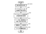
- FIG. 6 is a flowchart showing an example of the flow of setting value determination processing by the air conditioning control device 1 according to the first embodiment.
- the environmental state quantity acquisition unit 11 acquires the environmental state quantity of the air-conditioned space. Acquisition of such environmental state quantities is performed periodically.
- the thermal preference input unit 13 acquires comfort information input by the resident.
- the terminal used when comfort information is input to the thermal preference input unit 13 may be shared by a plurality of residents, or each of the plurality of residents may use a dedicated terminal.
- the resident may input the comfort information at a predetermined fixed time or interval, or may input the comfort information at any time when the resident is dissatisfied with the thermal environment.
- step S3 the resident information acquisition unit 12 acquires resident information about residents present in the air-conditioned space.
- the resident information acquiring unit 12 identifies the resident who has input the comfort information using various authentication techniques.
- the resident may be specified by identifying the terminal.
- the thermal preference input unit 13 supplies the input comfort information to the storage unit 14 .
- the resident information acquisition unit 12 supplies the acquired resident information to the storage unit 14 .
- the environmental state quantity acquisition unit 11 supplies the environmental state quantity at the time when the thermal preference input unit 13 acquires the comfort information to the storage unit 14 .
- the storage unit 14 stores the received comfort information, resident information, and environmental state quantity in association with each other.
- step S5 the comfort calculation unit 15 extracts the minimum value H low of the PMV values (environmental state quantity) when feeling hot, and extracts the PMV value (environmental state quantity) when feeling cold. Extract the maximum value C high among them.
- step S6 based on the minimum value H low when feeling hot and the maximum value C high when feeling cold extracted in step S5, the comfort calculation unit 15 determines whether the maximum value C high or more and H low The environmental state quantity within the following range is set as the comfort zone.
- the comfort calculation unit 15 supplies the set comfort region to the storage unit 14 and stores it. Then, the processes of steps S5 and S6 are performed by the number of residents present in the air-conditioned space.
- step S7 the setting value calculation unit 16 reads out the comfort zones of all the residents existing in the air-conditioned space stored in the storage unit 14, and calculates appropriate set environmental state quantities for these comfort zones.
- Set PMV_set the set value calculation unit 16 calculates the number of residents N whose comfort zone includes the set environmental state quantity PMV_set.
- step S9 the set value calculator 16 changes the set environmental state quantity PMV_set within the range of the settable environmental state quantity (-3 ⁇ PMV value ⁇ 3 in this example). Then, the set value calculation unit 16 searches for the set environmental state quantity PMV_set that maximizes the number of residents N including the set environmental state quantity PMV_set in the comfort zone. In step S ⁇ b>10 , the set value calculator 16 determines the set environmental state quantity PMV_set that maximizes the number of people N as the optimum set value, and transmits it to the air conditioner 2 .
- the air-conditioning control device 1 calculates the comfort zone based on the resident information, the comfort information, and the environmental state quantity of the residents present in the air-conditioned space. Then, based on the calculated comfort zone, the air conditioning control device 1 calculates setting values for the air conditioner so that the number of residents who are satisfied with the state of the air-conditioned space is maximized. As a result, the environmental state quantity in the air-conditioned space is set to a value that is included in the comfort zone of as many residents as possible among the plurality of residents present in the air-conditioned space. Satisfaction with the thermal environment can be maximized.
- the air conditioning control device 1 can control the air conditioner 2 so as to satisfy all three residents in the air-conditioned space.
- Embodiment 2 differs from Embodiment 1 in that when there is a resident who is not satisfied with the thermal environment of the air-conditioned space, the air-conditioning control device 1 prompts the resident to move to another zone.
- the same reference numerals are assigned to the parts that are common to the first embodiment, and detailed description thereof will be omitted.
- the air-conditioning target Based on the comfort zone of a plurality of residents existing in a certain zone of the space to be air-conditioned, when the optimum set value is set so that the number of residents N included in the comfort zone is maximized, depending on the situation, the air-conditioning target There is a possibility that some residents will be less satisfied with the thermal environment of the space. residents with such low satisfaction levels are unlikely to improve their satisfaction levels by remaining in their current zones. Therefore, in the second embodiment, movement from the current zone to another zone is encouraged to improve the satisfaction level of the thermal environment of the air-conditioned space, thereby further improving the satisfaction level of the residents.
- FIG. 7 is a block diagram showing an example of an air conditioning control device according to the second embodiment.
- the air conditioning control device 1 includes an environmental state quantity acquisition unit 11, a resident information acquisition unit 12, a thermal preference input unit 13, a storage unit 14, a comfort calculation unit 15, a set value calculation unit 16, a movement A pre-calculation unit 17 and an instruction unit 18 are provided.
- the movement destination calculation unit 17 sets the optimum setting value by the setting value calculation unit 16 based on the optimum setting values of all zones and the occupant's comfort area in all zones, and the optimum setting value is set to the own comfort area Identify residents not included in Further, the destination calculation unit 17 calculates the identified destination of the resident based on the comfort zone of the resident and the optimum setting values of all the zones. In the following description, such "a resident whose optimal set value is not included in his comfort zone" will be expressed as a "resident who is less satisfied with the thermal environment".
- the instruction unit 18 instructs the resident's destination zone based on the determination by the destination calculation unit 17 .
- a display or voice output unit such as a computer, a smartphone, a tablet, or a dedicated terminal used when comfort information is input to the thermal preference input unit 13 by the resident is used.
- the destination determination process will be described.
- a search is made for another zone having an optimum set value that is included in the comfort zone of the occupants who are less satisfied with the thermal environment in the current zone.
- the environmental state quantity is the PMV value.
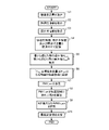
- FIG. 8 is a flowchart showing an example of the flow of destination determination processing by the air conditioning control device according to the second embodiment. First, prior to the movement destination determination process, the setting value determination process performed in steps S1 to S10 described in the first embodiment is performed.
- step S ⁇ b>11 the destination calculation unit 17 acquires the optimum setting value for each zone from the setting value calculation unit 16 .
- step S ⁇ b>12 the destination calculation unit 17 reads out and acquires the comfort zone of the resident in each zone stored in the storage unit 14 .
- step S13 the destination calculation unit 17 compares the optimum set value with the comfort zone of the occupants for each zone, and identifies the occupants who are less satisfied with the current thermal environment. Specifically, the movement destination calculation unit 17 identifies that the resident is a resident with a low degree of satisfaction with the thermal environment when the optimal set value is not included in the resident's comfort zone.
- step S14 the movement destination calculation unit 17 searches for a zone in which the optimum set value is set, which is included in the comfort zone of the resident. Then, the destination calculation unit 17 determines the zone found by the search as the destination zone. In step S ⁇ b>15 , the instruction unit 18 instructs the resident on the destination zone determined by the destination calculation unit 17 .
- the destination calculation unit 17 determines the zone where the difference between the optimum set value and the upper limit or lower limit of the comfort zone of the resident is the smallest as the destination zone.
- FIG. 9 is a flowchart showing an example of the flow of destination determination processing when a new resident joins the air-conditioned space. First, prior to the movement destination determination process, the setting value determination process performed in steps S1 to S10 described in the first embodiment is performed.
- step S21 the resident information acquisition unit 12 acquires resident information about a resident who has newly joined the air-conditioned space. Then, the destination calculation unit 17 identifies the newly added resident based on the acquired resident information.
- step S22 the destination calculation unit 17 acquires the comfort zone of the resident stored in the storage unit 14 based on the resident information of the identified resident.
- step S ⁇ b>23 the destination calculation unit 17 acquires the optimum setting value for each zone from the setting value calculation unit 16 .
- step S24 the destination calculation unit 17 searches for a zone in which the optimum set value is set, which is included in the comfort zone of the resident. Then, the destination calculation unit 17 determines the zone found by the search as the destination zone. In step S ⁇ b>25 , the instruction unit 18 instructs the resident on the destination zone determined by the destination calculation unit 17 .
- the destination of the zone where the resident is present is determined based on the set values for each zone.
- the present disclosure is not limited to the first and second embodiments described above, and various modifications and applications are possible without departing from the gist of the present disclosure. is.
- the PMV value is applied as the environmental state quantity of the air-conditioned space. Wind speed and radiation temperature, etc. can also be applied. Note that the amount of clothing and the amount of metabolism of the resident also affect the thermal sensation, so in the first and second embodiments, these can be included in the environmental state quantity. Further, quantities calculated using these environmental state quantities are also included in the environmental state quantities.
- the air conditioning control device 1 is configured separately from the air conditioner 2, but this is not limited to this example.
- the air conditioning control device 1 may function as part of a control device provided in the air conditioner 2 .
- one of the air conditioners 2 is equipped with the function of the air conditioning control device 1 so as to control the other air conditioners 2. good too.
- 1 air conditioning control device 2 air conditioner, 11 environmental state quantity acquisition unit, 12 resident information acquisition unit, 13 thermal preference input unit, 14 storage unit, 15 comfort calculation unit, 16 set value calculation unit, 17 destination calculation Unit, 18 Instruction unit, 31 Processing circuit, 32, 35 Input/output device, 33 Processor, 34 Memory.
Landscapes
- Engineering & Computer Science (AREA)
- Signal Processing (AREA)
- Physics & Mathematics (AREA)
- Fuzzy Systems (AREA)
- Mathematical Physics (AREA)
- Chemical & Material Sciences (AREA)
- Combustion & Propulsion (AREA)
- Mechanical Engineering (AREA)
- General Engineering & Computer Science (AREA)
- Air Conditioning Control Device (AREA)
Priority Applications (5)
| Application Number | Priority Date | Filing Date | Title |
|---|---|---|---|
| CN202180099553.5A CN117501054A (zh) | 2021-06-25 | 2021-06-25 | 空调控制装置和空调机 |
| US18/556,471 US20240318854A1 (en) | 2021-06-25 | 2021-06-25 | Air-conditioning controller and air-conditioning apparatus |
| EP21947185.1A EP4361514A4 (en) | 2021-06-25 | 2021-06-25 | AIR CONDITIONING CONTROL DEVICE AND AIR CONDITIONING |
| PCT/JP2021/024146 WO2022269903A1 (ja) | 2021-06-25 | 2021-06-25 | 空調制御装置および空気調和機 |
| JP2023529407A JP7483139B2 (ja) | 2021-06-25 | 2021-06-25 | 空調制御装置および空気調和機 |
Applications Claiming Priority (1)
| Application Number | Priority Date | Filing Date | Title |
|---|---|---|---|
| PCT/JP2021/024146 WO2022269903A1 (ja) | 2021-06-25 | 2021-06-25 | 空調制御装置および空気調和機 |
Publications (1)
| Publication Number | Publication Date |
|---|---|
| WO2022269903A1 true WO2022269903A1 (ja) | 2022-12-29 |
Family
ID=84544364
Family Applications (1)
| Application Number | Title | Priority Date | Filing Date |
|---|---|---|---|
| PCT/JP2021/024146 Ceased WO2022269903A1 (ja) | 2021-06-25 | 2021-06-25 | 空調制御装置および空気調和機 |
Country Status (5)
| Country | Link |
|---|---|
| US (1) | US20240318854A1 (https=) |
| EP (1) | EP4361514A4 (https=) |
| JP (1) | JP7483139B2 (https=) |
| CN (1) | CN117501054A (https=) |
| WO (1) | WO2022269903A1 (https=) |
Citations (7)
| Publication number | Priority date | Publication date | Assignee | Title |
|---|---|---|---|---|
| JP2014214975A (ja) * | 2013-04-25 | 2014-11-17 | 大成建設株式会社 | 快適環境選択支援装置および快適環境選択支援方法 |
| JP2016031220A (ja) | 2014-07-30 | 2016-03-07 | 株式会社東芝 | 空調最適化装置及び空調制御システム |
| WO2018163272A1 (ja) * | 2017-03-07 | 2018-09-13 | 三菱電機株式会社 | 空気調和装置、空気調和システム、および、制御方法 |
| WO2018220903A1 (ja) * | 2017-05-31 | 2018-12-06 | ダイキン工業株式会社 | 移動体の制御システム |
| JP2019100657A (ja) | 2017-12-06 | 2019-06-24 | アズビル株式会社 | 温冷感申告情報処理装置および方法 |
| JP2019124414A (ja) * | 2018-01-17 | 2019-07-25 | 日立グローバルライフソリューションズ株式会社 | 空調制御システム及び空調制御方法 |
| JP2020134124A (ja) | 2019-02-12 | 2020-08-31 | 大成建設株式会社 | 空調システムおよび空調装置の制御方法 |
Family Cites Families (6)
| Publication number | Priority date | Publication date | Assignee | Title |
|---|---|---|---|---|
| EP3705937B1 (en) * | 2014-06-30 | 2023-03-15 | View, Inc. | Computer-implemented control methods and systems for networks of optically switchable windows during reduced power availability |
| EP3344924A1 (en) * | 2015-09-03 | 2018-07-11 | Robert Bosch GmbH | Methods for determining a target operation point, target operation point determination devices, and user input devices |
| WO2019013014A1 (ja) * | 2017-07-12 | 2019-01-17 | 三菱電機株式会社 | 快適度表示装置 |
| US10708077B2 (en) * | 2017-11-21 | 2020-07-07 | Abb Schweiz Ag | Technologies for optimally individualized building automation |
| US11719458B2 (en) * | 2020-04-16 | 2023-08-08 | Robert Bosch Gmbh | HVAC control fine-grained occupancy pattern estimation |
| CN112927052A (zh) * | 2021-03-30 | 2021-06-08 | 福建诺诚数字科技有限公司 | 基于多人协同决策及多出发地的商户推荐方法和装置 |
-
2021
- 2021-06-25 WO PCT/JP2021/024146 patent/WO2022269903A1/ja not_active Ceased
- 2021-06-25 CN CN202180099553.5A patent/CN117501054A/zh active Pending
- 2021-06-25 EP EP21947185.1A patent/EP4361514A4/en not_active Withdrawn
- 2021-06-25 JP JP2023529407A patent/JP7483139B2/ja active Active
- 2021-06-25 US US18/556,471 patent/US20240318854A1/en active Pending
Patent Citations (7)
| Publication number | Priority date | Publication date | Assignee | Title |
|---|---|---|---|---|
| JP2014214975A (ja) * | 2013-04-25 | 2014-11-17 | 大成建設株式会社 | 快適環境選択支援装置および快適環境選択支援方法 |
| JP2016031220A (ja) | 2014-07-30 | 2016-03-07 | 株式会社東芝 | 空調最適化装置及び空調制御システム |
| WO2018163272A1 (ja) * | 2017-03-07 | 2018-09-13 | 三菱電機株式会社 | 空気調和装置、空気調和システム、および、制御方法 |
| WO2018220903A1 (ja) * | 2017-05-31 | 2018-12-06 | ダイキン工業株式会社 | 移動体の制御システム |
| JP2019100657A (ja) | 2017-12-06 | 2019-06-24 | アズビル株式会社 | 温冷感申告情報処理装置および方法 |
| JP2019124414A (ja) * | 2018-01-17 | 2019-07-25 | 日立グローバルライフソリューションズ株式会社 | 空調制御システム及び空調制御方法 |
| JP2020134124A (ja) | 2019-02-12 | 2020-08-31 | 大成建設株式会社 | 空調システムおよび空調装置の制御方法 |
Non-Patent Citations (1)
| Title |
|---|
| See also references of EP4361514A4 |
Also Published As
| Publication number | Publication date |
|---|---|
| CN117501054A (zh) | 2024-02-02 |
| US20240318854A1 (en) | 2024-09-26 |
| EP4361514A1 (en) | 2024-05-01 |
| JP7483139B2 (ja) | 2024-05-14 |
| JPWO2022269903A1 (https=) | 2022-12-29 |
| EP4361514A4 (en) | 2024-08-07 |
Similar Documents
| Publication | Publication Date | Title |
|---|---|---|
| EP3078919B1 (en) | Apparatus and method for controlling comfort temperature of air conditioning device or air conditioning system | |
| EP3284622B1 (en) | Air-conditioning control device | |
| US10082313B2 (en) | Instruction device, and air conditioning system | |
| JP5988196B2 (ja) | 機器制御装置、機器制御システムおよびプログラム | |
| CN111457565A (zh) | 空气调节设备及其控制方法、装置、电子设备 | |
| CN108759003B (zh) | 空调器的控制方法、空调器和计算机可读存储介质 | |
| JP2023166622A (ja) | 空気調和制御装置 | |
| JP6173784B2 (ja) | 空調エネルギー管理システム、方法、およびプログラム | |
| JP4623747B2 (ja) | 環境設備制御システム | |
| CN112283894A (zh) | 空调器、自学习和自动控制方法、控制装置和存储介质 | |
| JP6396542B2 (ja) | 空調制御装置、方法、およびプログラム | |
| CN113865038A (zh) | 一种空调控制方法、装置、空调器及存储介质 | |
| CN114771200A (zh) | 舱内的温度控制方法、系统及电动汽车 | |
| US20220253062A1 (en) | Moving body control system | |
| WO2022269903A1 (ja) | 空調制御装置および空気調和機 | |
| JP7126307B2 (ja) | 空調制御システム | |
| WO2020135816A1 (zh) | 基于感应阵列的控制方法、装置、存储介质及计算机设备 | |
| CN107044711B (zh) | 空调的控制方法及装置 | |
| CN117167910A (zh) | 用于控制空调器的方法及装置、空调器、存储介质 | |
| WO2021065680A1 (ja) | 制御システム | |
| CN116336633B (zh) | 一种中央空调变频方法、装置、电子设备及存储介质 | |
| JP7551013B2 (ja) | 空気調和機及び空気調和方法 | |
| AU2020434523B2 (en) | Air-conditioning system | |
| JP2024047953A (ja) | 制御装置および制御方法 | |
| CN118107345A (zh) | 空调控制的方法、装置、设备、存储介质和程序产品 |
Legal Events
| Date | Code | Title | Description |
|---|---|---|---|
| 121 | Ep: the epo has been informed by wipo that ep was designated in this application |
Ref document number: 21947185 Country of ref document: EP Kind code of ref document: A1 |
|
| WWE | Wipo information: entry into national phase |
Ref document number: 2023529407 Country of ref document: JP |
|
| WWE | Wipo information: entry into national phase |
Ref document number: 18556471 Country of ref document: US |
|
| WWE | Wipo information: entry into national phase |
Ref document number: 202180099553.5 Country of ref document: CN |
|
| WWE | Wipo information: entry into national phase |
Ref document number: 2021947185 Country of ref document: EP |
|
| NENP | Non-entry into the national phase |
Ref country code: DE |
|
| ENP | Entry into the national phase |
Ref document number: 2021947185 Country of ref document: EP Effective date: 20240125 |