WO2022269686A1 - エレベータの片開き式ドア装置 - Google Patents
エレベータの片開き式ドア装置 Download PDFInfo
- Publication number
- WO2022269686A1 WO2022269686A1 PCT/JP2021/023411 JP2021023411W WO2022269686A1 WO 2022269686 A1 WO2022269686 A1 WO 2022269686A1 JP 2021023411 W JP2021023411 W JP 2021023411W WO 2022269686 A1 WO2022269686 A1 WO 2022269686A1
- Authority
- WO
- WIPO (PCT)
- Prior art keywords
- toothed belt
- mass
- door
- belt
- pulley
- Prior art date
- Legal status (The legal status is an assumption and is not a legal conclusion. Google has not performed a legal analysis and makes no representation as to the accuracy of the status listed.)
- Ceased
Links
Images








Classifications
-
- B—PERFORMING OPERATIONS; TRANSPORTING
- B66—HOISTING; LIFTING; HAULING
- B66B—ELEVATORS; ESCALATORS OR MOVING WALKWAYS
- B66B13/00—Doors, gates, or other apparatus controlling access to, or exit from, cages or lift well landings
- B66B13/02—Door or gate operation
- B66B13/06—Door or gate operation of sliding doors
- B66B13/08—Door or gate operation of sliding doors guided for horizontal movement
-
- B—PERFORMING OPERATIONS; TRANSPORTING
- B66—HOISTING; LIFTING; HAULING
- B66B—ELEVATORS; ESCALATORS OR MOVING WALKWAYS
- B66B13/00—Doors, gates, or other apparatus controlling access to, or exit from, cages or lift well landings
- B66B13/02—Door or gate operation
- B66B13/14—Control systems or devices
- B66B13/143—Control systems or devices electrical
- B66B13/146—Control systems or devices electrical method or algorithm for controlling doors
Definitions
- the present disclosure relates to a single-opening door device for an elevator.
- a pair of car guide rails (not shown) and a pair of counterweight guide rails (not shown) are installed in the hoistway 1 .
- a pair of car guide rails guides the rise and fall of the car 8 .
- a pair of counterweight guide rails guides the lifting and lowering of the counterweight 9 .
- the second door body 27 has a second door panel 33 and a second door hanger 34 .
- the second door hanger 34 is fixed to the top of the second door panel 33 .
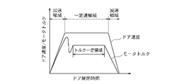
- the door controller 13 controls the opening/closing operation of the first door body 26 by controlling the door motor 22 . Further, the door controller 13 maintains a constant maximum speed for 0.5 seconds or more during the opening/closing operation of the first door body 26 .
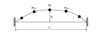
- Expression (5) indicates the amount of displacement of the i-th mass point in FIG.
- vibration of the toothed belt 25 can be suppressed.
- noise generated during the opening and closing operations of the first door body 26 and the second door body 27 can be reduced.
- the maximum speed during the opening/closing operation of the first door body 26, that is, the constant speed is 400 mm/mm. s.
- the pitch of the plurality of belt teeth 25a is 5 mm. In this case, the toothed belt 25 is vibrated at 80 Hz when the first door body 26 is opened and closed.
- the linear density ⁇ of the toothed belt 25 is 0.065 kg/m
- the fixed pitch L which is the distance between the center of the first pulley 23 and the center of the second pulley 24 is 1500 mm
- the motor torque of the door motor 22 is constant.
- the tension T of the toothed belt 25 is 150N.
- Embodiment 1 since the mass body 29 is attached to the toothed belt 25, in the toothed belt 25, excitation vibration due to meshing with the first pulley 23 and the second pulley 24, Resonance with string vibration is suppressed.
- the mass of the mass body 29 is 20% or more and 100% or less of the mass of the toothed belt 25 per meter. Therefore, bending of the toothed belt 25 due to the mass of the mass body 29 can be sufficiently suppressed.
- the door controller 13 maintains a constant maximum speed for 0.5 seconds or more during the opening/closing operation of the first door body 26 . Therefore, by simply changing the time for maintaining a constant maximum speed, it is possible to easily deal with differences in the width of the car entrance and exit, and it is possible to easily set the software for controlling the opening/closing operation. .
- Embodiment 1 since the mass body 29 is attached to the toothed belt 25, it is possible to suppress the vibration of the toothed belt 25 while facilitating software settings.
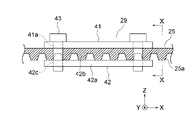
- FIG. 9 is a side view of mass body 29 of FIG. 10 is a cross-sectional view taken along line XX of FIG. 9.
- FIG. 9 is a side view of mass body 29 of FIG. 10 is a cross-sectional view taken along line XX of FIG. 9.
- the mass body 29 has a flat first member 41 , a second member 42 and a plurality of fasteners 43 .
- the first member 41 is applied to the surface of the toothed belt 25 opposite to the plurality of belt teeth 25a.
- the first member 41 is provided with a plurality of through holes 41a.
- the second member 42 has a flat base portion 42a and a plurality of projections 42b as stopper portions.
- the base portion 42a is in contact with the tip surfaces of the plurality of belt teeth 25a.
- the plurality of convex portions 42b each protrude from the base portion 42a toward the first member 41 side.
- Each protrusion 42b is inserted into a recess between two adjacent belt teeth 25a and fitted into the recess. That is, the plurality of protrusions 42b mesh with the plurality of belt teeth 25a. Thereby, the plurality of belt teeth 25 a restricts movement of the mass body 29 with respect to the toothed belt 25 in the longitudinal direction of the toothed belt 25 .
- the longitudinal direction of the toothed belt 25 is parallel to the X-axis in FIG.
- a plurality of screw holes 42c are provided in the base portion 42a.
- a bolt for example, is used as each fastener 43 .
- Each fastener 43 is passed through the corresponding through hole 41a and screwed into the corresponding screw hole 42c.
- Each fastener 43 is arranged outside the toothed belt 25 in the width direction of the toothed belt 25 .
- the width direction of the toothed belt 25 is the direction parallel to the depth direction of the car 8 and the direction parallel to the Y axis in FIG.
- the toothed belt 25 is sandwiched between the first member 41 and the second member 42 by screwing each fastener 43 into the corresponding screw hole 42c.
- FIG. 11 is a side view showing a first modified example of the mass body 29 of FIG. 12 is a cross-sectional view taken along line XII-XII in FIG. 11.
- FIG. 11 is a side view showing a first modified example of the mass body 29 of FIG. 12 is a cross-sectional view taken along line XII-XII in FIG. 11.
- the mass body 29 in the first modified example has a member to be fastened 44 and a plurality of fasteners 45 .
- the fastened member 44 has a flat plate-like first portion 44a, a flat plate-like second portion 44b, and a connecting portion 44c.
- the first portion 44a is applied to the surface of the toothed belt 25 opposite to the plurality of belt teeth 25a.
- the second portion 44b is in contact with the tip surfaces of the plurality of belt teeth 25a.
- the connecting portion 44c connects the first portion 44a and the second portion 44b.
- each fastener 45 is used as each fastener 45 .
- Each fastener 45 is passed through the corresponding through hole 44d and screwed into the corresponding screw hole 44e.
- the toothed belt 25 is sandwiched between the first portion 44a and the second portion 44b.
- a plurality of fasteners 45 are arranged only on the outside of one end in the width direction of the toothed belt 25 .
- the connecting portion 44c is positioned outside the other end portion of the toothed belt 25 in the width direction.
- the mass body 29 of the first modified example since the plurality of fasteners 45 are arranged only outside one end of the toothed belt 25 in the width direction, the mass body 29 is prevented from interfering with other devices. can do.
- the second portion 44b may be provided with a plurality of projections as stopper portions.
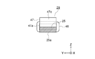
- FIG. 13 is a side view showing a second modification of the mass body 29 of FIG. 14 is a cross-sectional view along line XIV-XIV in FIG. 13.
- FIG. 13 is a side view showing a second modification of the mass body 29 of FIG. 14 is a cross-sectional view along line XIV-XIV in FIG. 13.
- the mass body 29 in the second modified example has a pair of endless connectors 46 and a member 47 to be connected.
- the connected member 47 has a flat main portion 47a, a first projecting portion 47b, and a second projecting portion 47c.
- a concave portion 47 d is formed on the surface of the connected member 47 opposite to the toothed belt 25 .
- the recessed portion 47d is formed between the first protruding portion 47b and the second protruding portion 47c of the member 47 to be connected.
- each connecting tool 46 functions as a stopper portion.
- the shift of the mass body 29 with respect to the toothed belt 25 can also be suppressed by the mass body 29 of the second modification. Further, it is possible to suppress an increase in the size of the mass body 29 in the width direction of the toothed belt 25, and to suppress interference between the mass body 29 and other devices.
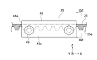
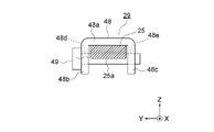
- FIG. 15 is a side view showing a third modified example of the mass body 29 of FIG. 16 is a cross-sectional view taken along line XVI--XVI of FIG. 15.
- FIG. 15 is a side view showing a third modified example of the mass body 29 of FIG. 16 is a cross-sectional view taken along line XVI--XVI of FIG. 15.
- the mass body 29 in the third modified example has a member to be fastened 48 and a plurality of fasteners 49 .
- the fastened member 48 has a flat plate-like main portion 48a, a flat plate-like first projecting portion 48b, and a flat plate-like second projecting portion 48c.
- the main portion 48a is in contact with the surface of the toothed belt 25 opposite to the plurality of belt teeth 25a.
- the first protruding portion 48b and the second protruding portion 48c are spaced apart from each other in the width direction of the toothed belt 25 and protrude from the main portion 48a toward the toothed belt 25 side.
- the toothed belt 25 is passed between the first projecting portion 48b and the second projecting portion 48c.
- a plurality of through holes 48d are provided in the first projecting portion 48b.
- a plurality of screw holes 48e are provided in the second projecting portion 48c.
- each fastener 49 is used as each fastener 49 .
- Each fastener 49 is passed through the corresponding through hole 48d and screwed into the corresponding screw hole 48e.
- a seamless belt is used as the toothed belt 25.
- the seamless toothed belt 25 is endless before it is wound around the first pulley 23 and the second pulley 24 .
- the toothed belt 25 of Figure 17 has a first end 25b and a second end 25c.
- a mass body 29 connects the first end portion 25b and the second end portion 25c.
- the plurality of protrusions 42b mesh with the plurality of belt teeth 25a, thereby preventing the first end 25b and the second end 25c from coming off the mass body 29.
- the length of the toothed belt 25 can be easily adjusted.
- FIG. 18 is a side view showing the essential parts of the toothed belt 25 according to Embodiment 2.
- the configuration of the car door device 12 and the configuration of the elevator are the same as those of the first embodiment except for the configuration of the toothed belt 25 shown in FIG.
- a part of the toothed belt 25 in the second embodiment in the longitudinal direction is provided with a weight portion 25d.
- M 1 be the mass per unit length of the weight portion 25d.
- M 0 be the mass per unit length of the other portion 25e.
- the other portion 25e is a portion of the toothed belt 25 excluding the weight portion 25d.
- the mass M 1 is made more than twice the mass M 0 by, for example, making the material density of the weight portion 25d higher than that of the other portion 25e. That is, M 1 ⁇ 2 ⁇ M 0 .
- the weight part 25d is located at a position where it moves in the direction opposite to the belt gripper 28 when the first door body 26 is opened and closed. That is, the weight portion 25d is located at the same position as the mass body 29 in the first embodiment.
- the mass body 29 of Embodiment 1 or the weight portion 25d of Embodiment 2 may be applied to the toothed belt of the landing door device 14.
- the door motor 22 shown in FIGS. 2 and 3 is a thin motor.
- a thin motor is a motor whose dimension in the direction parallel to the axis of rotation is smaller than the dimension in the direction perpendicular to the axis of rotation.
- the door motor 22 may be a body length motor.
- a body-length motor is a motor whose dimension in the direction parallel to the axis of rotation is larger than the dimension in the direction perpendicular to the axis of rotation.
- the rotating shaft of the door motor 22 is arranged parallel to the depth direction of the car 8 .
- a gear (not shown) between the door motor 22 and the first pulley 23, the direction of the rotating shaft of the door motor 22 may be changed.
- the first pulley 23 is directly rotated by the door motor 22 .
- a speed reduction mechanism (not shown) may be provided between the door motor 22 and the first pulley 23 .
- the reduction mechanism has a first transmission belt and a reduction pulley. The diameter of the reduction pulley is larger than the diameter of the first pulley 23 .
- the first transmission belt transmits the output of the door motor 22 to the reduction pulley.
- the door motor 22 When a speed reduction mechanism is provided between the door motor 22 and the first pulley 23, the door motor 22 may be arranged at a position away from the first pulley 23, for example, on the door beam 21.
- the reduction pulley may be arranged coaxially with the first pulley 23 .
- the first pulley 23 rotates together with the reduction pulley.
- the speed reduction pulley may be arranged at a position away from the first pulley 23 .
- the reduction mechanism has a transmission pulley and a second transmission belt in addition to the first transmission belt and reduction pulley.
- the transmission pulley is coaxially arranged with the reduction pulley and rotates therewith.
- the second transmission belt transmits rotation of the transmission pulley to the first pulley 23 .
- the number of door bodies may be one or three or more.
- the layout of the entire elevator is not limited to the layout in FIG.
- the roping scheme may be a 2:1 roping scheme.
- the elevator may be a machine room-less elevator, a double-deck elevator, a one-shaft multi-car elevator, or the like.
- the one-shaft multi-car system is a system in which an upper car and a lower car placed directly below the upper car independently ascend and descend a common hoistway.
Landscapes
- Elevator Door Apparatuses (AREA)
- Power-Operated Mechanisms For Wings (AREA)
Abstract
Description
実施の形態1.
図1は、実施の形態1によるエレベータを示す概略の構成図である。図において、昇降路1の上には、機械室2が設けられている。機械室2には、巻上機3、そらせ車4、及びエレベータ制御装置5が設置されている。








次に、図18は、実施の形態2による歯付きベルト25の要部を示す側面図である。図18に示す歯付きベルト25の構成を除いて、かごドア装置12の構成、及びエレベータの構成は、実施の形態1と同様である。
Claims (11)
- 第1プーリ、
前記第1プーリに対して間隔をおいて配置されている第2プーリ、
前記第1プーリ及び前記第2プーリに巻き掛けられており、かつ複数のベルト歯を有している歯付きベルト、
前記歯付きベルトに取り付けられているベルト掴み具、
前記ベルト掴み具を介して前記歯付きベルトに接続されており、前記第1プーリ及び前記第2プーリの回転による前記歯付きベルトの移動によって開閉動作するドア本体、及び
前記歯付きベルトに取り付けられており、前記歯付きベルトとともに移動する質量体
を備え、
前記質量体は、前記ドア本体の開閉動作時に前記ベルト掴み具とは反対方向へ移動する位置において、前記歯付きベルトに取り付けられているエレベータの片開き式ドア装置。 - 前記歯付きベルトとして、繋ぎ目のないベルトが用いられている請求項1記載のエレベータの片開き式ドア装置。
- 前記歯付きベルトは、第1端部と第2端部とを有しており、
前記第1端部と前記第2端部とは、前記質量体によって繋がれている請求項1記載のエレベータの片開き式ドア装置。 - 前記質量体の質量は、前記ドア本体の質量の10%以下である請求項1から請求項3までのいずれか1項に記載のエレベータの片開き式ドア装置。
- 前記質量体の質量は、前記歯付きベルトの1メートル当たりの質量の20%以上、100%以下である請求項1から請求項4までのいずれか1項に記載のエレベータの片開き式ドア装置。
- 前記質量体は、ストッパ部を有しており、
前記ストッパ部は、隣り合う2つの前記ベルト歯の間に挿入されており、前記歯付きベルトの長手方向への前記歯付きベルトに対する前記質量体の移動を規制している請求項1から請求項5までのいずれか1項に記載のエレベータの片開き式ドア装置。 - 前記質量体は、被締結部材と、前記被締結部材に締結されている締結具とを有しており、
前記締結具は、前記歯付きベルトの幅方向の一端部の外側のみに配置されている請求項1から請求項6までのいずれか1項に記載のエレベータの片開き式ドア装置。 - 前記質量体は、無端状の連結具と、前記連結具によって前記歯付きベルトに連結されている被連結部材とを有しており、
前記被連結部材における前記歯付きベルトとは反対側の面には、凹部が形成されており、
前記連結具は、隣り合う2つの前記ベルト歯の間と、前記凹部とに挿入されている請求項1から請求項5までのいずれか1項に記載のエレベータの片開き式ドア装置。 - 前記質量体は、被締結部材と、前記被締結部材に締結されている締結具とを有しており、
前記締結具は、前記歯付きベルトの幅方向に平行に配置されており、かつ、隣り合う2つの前記ベルト歯の間に挿入されている請求項1から請求項5までのいずれか1項に記載のエレベータの片開き式ドア装置。 - 前記ドア本体の開閉動作を制御するドアコントローラ
をさらに備え、
前記ドアコントローラは、前記ドア本体の開閉動作中に、一定の最高速度を0.5秒以上維持する請求項1から請求項9までのいずれか1項に記載のエレベータの片開き式ドア装置。 - 第1プーリ、
前記第1プーリに対して間隔をおいて配置されている第2プーリ、
前記第1プーリ及び前記第2プーリに巻き掛けられており、かつ複数のベルト歯を有している歯付きベルト、
前記歯付きベルトに取り付けられているベルト掴み具、及び
前記ベルト掴み具を介して前記歯付きベルトに接続されており、前記第1プーリ及び前記第2プーリの回転による前記歯付きベルトの移動によって開閉動作するドア本体
を備え、
前記歯付きベルトの長手方向の一部には、重量部が設けられており、
前記重量部における単位長さ当たりの質量は、前記歯付きベルトの前記重量部を除く部分における単位長さ当たりの質量の2倍以上であり、
前記重量部は、前記ドア本体の開閉動作時に前記ベルト掴み具とは反対方向へ移動する位置に位置しているエレベータの片開き式ドア装置。
Priority Applications (4)
| Application Number | Priority Date | Filing Date | Title |
|---|---|---|---|
| JP2023529214A JP7475548B2 (ja) | 2021-06-21 | 2021-06-21 | エレベータの片開き式ドア装置 |
| CN202180099411.9A CN117500742A (zh) | 2021-06-21 | 2021-06-21 | 电梯的单开式门装置 |
| PCT/JP2021/023411 WO2022269686A1 (ja) | 2021-06-21 | 2021-06-21 | エレベータの片開き式ドア装置 |
| DE112021007859.3T DE112021007859T5 (de) | 2021-06-21 | 2021-06-21 | Ein-Seiten-Öffnung-Typ-Türvorrichtung für Aufzüge |
Applications Claiming Priority (1)
| Application Number | Priority Date | Filing Date | Title |
|---|---|---|---|
| PCT/JP2021/023411 WO2022269686A1 (ja) | 2021-06-21 | 2021-06-21 | エレベータの片開き式ドア装置 |
Publications (1)
| Publication Number | Publication Date |
|---|---|
| WO2022269686A1 true WO2022269686A1 (ja) | 2022-12-29 |
Family
ID=84544313
Family Applications (1)
| Application Number | Title | Priority Date | Filing Date |
|---|---|---|---|
| PCT/JP2021/023411 Ceased WO2022269686A1 (ja) | 2021-06-21 | 2021-06-21 | エレベータの片開き式ドア装置 |
Country Status (4)
| Country | Link |
|---|---|
| JP (1) | JP7475548B2 (ja) |
| CN (1) | CN117500742A (ja) |
| DE (1) | DE112021007859T5 (ja) |
| WO (1) | WO2022269686A1 (ja) |
Citations (2)
| Publication number | Priority date | Publication date | Assignee | Title |
|---|---|---|---|---|
| JPH03223545A (ja) * | 1990-01-26 | 1991-10-02 | Toshiba Corp | ベルト連結具 |
| JP2019001585A (ja) * | 2017-06-13 | 2019-01-10 | 東芝エレベータ株式会社 | エレベータのフロアドア開閉装置および異常判定装置 |
Family Cites Families (2)
| Publication number | Priority date | Publication date | Assignee | Title |
|---|---|---|---|---|
| JP2008168957A (ja) | 2007-01-09 | 2008-07-24 | Mitsubishi Electric Corp | エレベータのかごドア開閉装置 |
| CN109830164A (zh) * | 2019-01-30 | 2019-05-31 | 西南石油大学 | 一种具有平稳运行功能且能耗较低的教学用电梯模型 |
-
2021
- 2021-06-21 JP JP2023529214A patent/JP7475548B2/ja active Active
- 2021-06-21 CN CN202180099411.9A patent/CN117500742A/zh active Pending
- 2021-06-21 DE DE112021007859.3T patent/DE112021007859T5/de active Pending
- 2021-06-21 WO PCT/JP2021/023411 patent/WO2022269686A1/ja not_active Ceased
Patent Citations (2)
| Publication number | Priority date | Publication date | Assignee | Title |
|---|---|---|---|---|
| JPH03223545A (ja) * | 1990-01-26 | 1991-10-02 | Toshiba Corp | ベルト連結具 |
| JP2019001585A (ja) * | 2017-06-13 | 2019-01-10 | 東芝エレベータ株式会社 | エレベータのフロアドア開閉装置および異常判定装置 |
Also Published As
| Publication number | Publication date |
|---|---|
| CN117500742A (zh) | 2024-02-02 |
| JP7475548B2 (ja) | 2024-04-26 |
| DE112021007859T5 (de) | 2024-04-11 |
| JPWO2022269686A1 (ja) | 2022-12-29 |
Similar Documents
| Publication | Publication Date | Title |
|---|---|---|
| US5533595A (en) | Traction-type elevator | |
| CA2512565C (en) | Elevator | |
| JP5873884B2 (ja) | エレベータ | |
| CN1245324C (zh) | 电梯装置 | |
| JP4975234B2 (ja) | エレベータ装置 | |
| EP2776355B1 (en) | Elevator system | |
| JP5044102B2 (ja) | エレベータの多段ケージの各ケージを正確に位置決めする装置 | |
| MXPA03009456A (es) | Mejoras para elevador de pasajeros o carga con base al uso de cadenas, contrapesos y servomotores. | |
| EP1727760B1 (en) | Elevator | |
| JPH11157762A (ja) | エレベーター | |
| JPH07252062A (ja) | エレベータのドア装置及びその調整方法 | |
| JP7475548B2 (ja) | エレベータの片開き式ドア装置 | |
| KR20120043792A (ko) | 카운터 웨이트가 없는 엘리베이터 | |
| JPWO2009098772A1 (ja) | エレベータ装置 | |
| EP1741660A1 (en) | Elevator apparatus | |
| JPH03177288A (ja) | トラクション式エレベータ装置 | |
| JPH11139718A (ja) | エレベータの主ロープ振れ止め装置 | |
| JP7100304B1 (ja) | 調速機及びエレベータ | |
| JP7325639B2 (ja) | エレベータのドア装置及びそのベルト掴み具 | |
| JPH10167626A (ja) | 斜行エレベーターのかご装置 | |
| CN206798898U (zh) | 电梯及其安全钳 | |
| JP2024180045A (ja) | ダブルデッキエレベータ | |
| HK1101907B (zh) | 电梯 | |
| HK1101906B (en) | Elevator | |
| JP2005231869A (ja) | エレベータ装置 |
Legal Events
| Date | Code | Title | Description |
|---|---|---|---|
| 121 | Ep: the epo has been informed by wipo that ep was designated in this application |
Ref document number: 21946977 Country of ref document: EP Kind code of ref document: A1 |
|
| ENP | Entry into the national phase |
Ref document number: 2023529214 Country of ref document: JP Kind code of ref document: A |
|
| WWE | Wipo information: entry into national phase |
Ref document number: 202180099411.9 Country of ref document: CN |
|
| WWE | Wipo information: entry into national phase |
Ref document number: 112021007859 Country of ref document: DE |
|
| 122 | Ep: pct application non-entry in european phase |
Ref document number: 21946977 Country of ref document: EP Kind code of ref document: A1 |