WO2022264787A1 - ステータ及び回転電動機 - Google Patents
ステータ及び回転電動機 Download PDFInfo
- Publication number
- WO2022264787A1 WO2022264787A1 PCT/JP2022/021828 JP2022021828W WO2022264787A1 WO 2022264787 A1 WO2022264787 A1 WO 2022264787A1 JP 2022021828 W JP2022021828 W JP 2022021828W WO 2022264787 A1 WO2022264787 A1 WO 2022264787A1
- Authority
- WO
- WIPO (PCT)
- Prior art keywords
- yoke
- stator
- teeth
- insulator
- coil
- Prior art date
Links
- 239000012212 insulator Substances 0.000 claims abstract description 54
- 230000002093 peripheral effect Effects 0.000 claims description 30
- 238000004804 winding Methods 0.000 claims description 11
- 238000012986 modification Methods 0.000 description 19
- 230000004048 modification Effects 0.000 description 19
- 238000005452 bending Methods 0.000 description 10
- 230000004907 flux Effects 0.000 description 10
- 230000001965 increasing effect Effects 0.000 description 5
- 230000002708 enhancing effect Effects 0.000 description 2
- 238000010030 laminating Methods 0.000 description 2
- 229910000831 Steel Inorganic materials 0.000 description 1
- 238000013459 approach Methods 0.000 description 1
- 238000010292 electrical insulation Methods 0.000 description 1
- 229910052751 metal Inorganic materials 0.000 description 1
- 239000002184 metal Substances 0.000 description 1
- 238000000034 method Methods 0.000 description 1
- 229910001172 neodymium magnet Inorganic materials 0.000 description 1
- 229920006395 saturated elastomer Polymers 0.000 description 1
- 239000010959 steel Substances 0.000 description 1
- 239000000126 substance Substances 0.000 description 1
- 229920003002 synthetic resin Polymers 0.000 description 1
- 239000000057 synthetic resin Substances 0.000 description 1
- 229910000859 α-Fe Inorganic materials 0.000 description 1
Images


Classifications
-
- H—ELECTRICITY
- H02—GENERATION; CONVERSION OR DISTRIBUTION OF ELECTRIC POWER
- H02K—DYNAMO-ELECTRIC MACHINES
- H02K1/00—Details of the magnetic circuit
- H02K1/06—Details of the magnetic circuit characterised by the shape, form or construction
- H02K1/12—Stationary parts of the magnetic circuit
- H02K1/14—Stator cores with salient poles
- H02K1/146—Stator cores with salient poles consisting of a generally annular yoke with salient poles
-
- H—ELECTRICITY
- H02—GENERATION; CONVERSION OR DISTRIBUTION OF ELECTRIC POWER
- H02K—DYNAMO-ELECTRIC MACHINES
- H02K3/00—Details of windings
- H02K3/32—Windings characterised by the shape, form or construction of the insulation
- H02K3/325—Windings characterised by the shape, form or construction of the insulation for windings on salient poles, such as claw-shaped poles
-
- H—ELECTRICITY
- H02—GENERATION; CONVERSION OR DISTRIBUTION OF ELECTRIC POWER
- H02K—DYNAMO-ELECTRIC MACHINES
- H02K3/00—Details of windings
- H02K3/32—Windings characterised by the shape, form or construction of the insulation
- H02K3/34—Windings characterised by the shape, form or construction of the insulation between conductors or between conductor and core, e.g. slot insulation
-
- H—ELECTRICITY
- H02—GENERATION; CONVERSION OR DISTRIBUTION OF ELECTRIC POWER
- H02K—DYNAMO-ELECTRIC MACHINES
- H02K2213/00—Specific aspects, not otherwise provided for and not covered by codes H02K2201/00 - H02K2211/00
- H02K2213/03—Machines characterised by numerical values, ranges, mathematical expressions or similar information
Definitions
- the present disclosure relates generally to stators and rotating electric motors. More particularly, the present disclosure relates to stators with insulators and rotary electric motors with the stators.
- Patent Document 1 discloses an electric motor that includes a rotor that is rotatable about a rotation axis, and a stator that has a stator core and windings wound around the stator core.
- the present disclosure has been made in view of the above reasons, and an object thereof is to provide a stator and a rotary electric motor including the stator that can reduce the possibility that the torque of the rotary electric motor will decrease.
- a stator includes a stator core, an insulator, and a coil.
- the stator core has an annular yoke and a plurality of teeth protruding from the yoke to the inside of the yoke.
- the insulator covers at least part of the stator core.
- the coil is installed on at least one tooth among the plurality of teeth via the insulator.
- the insulator has a first surface facing the coil and a second surface facing the yoke.
- the first surface is perpendicular to the protruding direction of the teeth.
- the second surface includes a first vertical surface perpendicular to the protruding direction of the tooth, and a first bent surface that bends toward the first surface with respect to the vertical surface.
- the yoke has an inner peripheral surface facing the second surface.
- a rotary electric motor includes the stator and the rotor.
- the rotor is positioned inside the stator and rotates relative to the stator.
- FIG. 1 is a cross-sectional view of a rotary electric motor according to an embodiment.
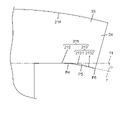
- FIG. 2 is a partial cross-sectional view of the stator according to the embodiment.
- FIG. 3 is a plan view of a main part of a stator according to Modification 1.
- FIG. 4 is a plan view of a main part of a stator according to Modification 2.
- FIG. 5 is a partial cross-sectional view of a stator according to another modification.
- a rotary electric motor 1 according to an embodiment of the present disclosure will be described in detail with reference to the drawings.
- Each drawing described in the following embodiments is a schematic drawing, and the ratio of the size and thickness of each component in the drawing does not necessarily reflect the actual dimensional ratio. .
- the following embodiments (including modifications) may be combined as appropriate and implemented.
- FIG. 1 is a cross-sectional view of a rotary electric motor 1 according to an embodiment.
- FIG. 2 is a cross-sectional view of part of the stator 2 according to the embodiment.
- the rotary electric motor 1 includes a stator 2 and a rotor 3 arranged inside the stator 2 and rotating with respect to the stator 2, as shown in FIG. A gap is provided between the stator 2 and the rotor 3, and the rotor 3 rotates around the rotation axis A1 in a non-contact state with the stator 2. As shown in FIG.
- the stator 2 includes a stator core 20, insulators 4, and coils 5, as shown in FIGS.
- the stator core 20 has an annular yoke 21 and a plurality of (12 in this embodiment) teeth 22 protruding from the yoke 21 to the inside of the yoke 21 .
- Insulator 4 covers at least part of stator core 20 .
- Coil 5 is installed on at least one tooth 22 among a plurality of teeth 22 via insulator 4 .
- the insulator 4 has a first surface 41 facing the coil 5 and a second surface 42 facing the yoke 21 .
- the first surface 41 is perpendicular to the projecting direction of the teeth 22 .
- the second surface 42 includes a first vertical surface 421 perpendicular to the protruding direction of the teeth 22 and a first bent surface 422 bent toward the first surface 41 with respect to the first vertical surface 421 .
- the yoke 21 also has an inner peripheral surface 211 facing the second surface 42 of the insulator 4 .
- FIG. 1 the term “perpendicular” as used in the present disclosure includes not only perfect perpendicularity but also substantially perpendicularity in which two planes form an angle of 90 ⁇ 5°.
- parallel in the present disclosure includes not only complete parallelism but also substantially parallelism where the angle formed by two planes is within 5°.
- the rotary electric motor 1 of this embodiment is, for example, a brushless motor. As shown in FIG. 1 , the rotary electric motor 1 has a stator 2 and a rotor 3 rotating with respect to the stator 2 .
- the stator 2 has a stator core 20, an insulator 4, and 12 coils 5, for example.
- the stator core 20 has an annular yoke 21 and, for example, 12 teeth 22 protruding from the yoke 21 to the inside of the yoke 21 .
- Each coil 5 is installed on each tooth 22 via an insulator 4 .
- the rotor 3 has a rotor core 30 , eight first permanent magnets 31 , eight second permanent magnets 34 , and an output shaft 32 .
- first permanent magnets 31 and eight second permanent magnets 34 are held by the rotor core 30 .
- the rotor 3 is arranged inside the stator 2 with an air gap therebetween and rotates about the rotation axis A1 with respect to the stator 2 .
- the magnetic flux generated when current flows through the coil 5 interacts with the magnetic flux generated by the first permanent magnet 31 and the second permanent magnet 34 to generate a force to rotate the rotor 3. .
- Rotational force (driving force) of the rotor 3 is transmitted from the output shaft 32 to the outside.
- stator core 20 of the stator 2 as shown in FIG. 21 has, for example, 12 teeth 22 protruding inside.
- the stator core 20 of the present embodiment is composed of, for example, 12 divided cores 23 arranged in the circumferential direction about the rotation axis A1.
- the split core 23 is formed, for example, by laminating a plurality of thin plate-like magnetic bodies in the axial direction of the rotation axis A1.
- each split core 23 has a yoke portion 24 and one tooth 22 protruding from the inside of the yoke portion 24 in the radial direction of the yoke 21 (the radial direction about the rotation axis A1).
- the yoke portion 24 has an arc shape centered on the axis of the yoke 21 (rotational axis A1) when viewed from the axial direction of the yoke 21 (axial direction of the rotational axis A1). That is, in the present embodiment, as shown in FIGS. 1 and 2, twelve split cores 23 are arranged in the circumferential direction about the rotation axis A1, so that the twelve yoke portions 24 are arranged around the rotation axis A1. A centered annular yoke 21 is formed. Moreover, 12 teeth 22 are arrange
- the number of split cores 23 is not limited to 12, and may be 11 or less, or 13 or more.
- the stator core 20 may not be composed of the split cores 23, but may be one component that cannot be split.
- each tooth 22 has a trunk portion 221 whose width is constant along the direction in which each tooth 22 protrudes, and a leg portion 222 whose width increases as it approaches the rotation axis A1 along the direction of protrusion.
- the imaginary line 8 indicates the projecting direction of the teeth 22, and does not have a substance.
- the stator 2 has an insulator 4 .
- the insulator 4 is made of synthetic resin, for example, and has electrical insulation.
- the insulator 4 covers a region including at least a portion of the trunk portion 221 and the leg portion 222 of each tooth 22 and at least a portion of an inner peripheral surface 211 (described later) of the yoke 21 .
- a coil 5 is installed on each tooth 22 via an insulator 4, as shown in FIG. That is, the 12 coils 5 correspond to the 12 teeth 22 on a one-to-one basis, and each coil 5 is formed of windings 51 wound around the corresponding teeth 22 via the insulators 4 .
- As a method of winding the winding 51 for example, concentrated winding is adopted.
- a wire 51 forming the coil 5 is, for example, a round wire having a circular cross section.
- the insulator 4 has a first surface 41 facing the coil 5 wound around the tooth 22 and a second surface 42 facing the yoke 21, as shown in FIG.
- the first surface 41 is perpendicular to the projecting direction of the teeth 22 . That is, the imaginary plane 9 including the first surface 41 and the imaginary line 8 indicating the projecting direction of the teeth 22 perpendicularly intersect.
- the second surface 42 has a first vertical surface 421 perpendicular to the protruding direction of the teeth 22 and a first bent surface 422 that bends toward the first surface 41 with respect to the first vertical surface 421 . That is, the virtual plane 10 including the first vertical plane 421 and the virtual line 8 perpendicularly intersect.
- first curved surface 422 is, for example, a plane that is continuous with the first vertical surface 421 at an angle larger than 0° and smaller than 180°.
- first curved surface 422 may be a curved surface, or may include a plurality of continuous planes forming an angle larger than 0° and smaller than 180° with each other.
- the insulator 4 also has a third surface 43 and a fourth surface 44 opposite to each other.
- the third surface 43 is a surface facing the coil 5
- the fourth surface 44 is a surface facing the trunk portion 221 of the tooth 22 .
- Each of the third surface 43 and the fourth surface 44 is parallel to the projecting direction of the teeth 22 . That is, each of the third surface 43 and the fourth surface 44 is perpendicular to the first vertical surfaces 421 of the first surface 41 and the second surface 42, respectively.
- the thickness T1 of the insulator 4 between the first surface 41 and the first vertical surface 421 is thicker than the thickness T2 of the insulator 4 between the third surface 43 and the fourth surface 44.
- the thickness T1 may be thinner than the thickness T2 or may be equal to the thickness T2.
- the insulator 4 also has a fifth surface 45 and a sixth surface 46 opposite to each other.
- the fifth surface 45 is a surface facing the coil 5
- the sixth surface 46 is a surface facing the leg portion 222 of the tooth 22 .
- the first surface 41, the third surface 43, and the fifth surface 45 are continuous with each other at an angle larger than 0° and smaller than 180°, and constitute the inner surface of the insulator 4 around which the coil 5 is wound.
- the first plane 41 is, for example, perpendicular to the third plane 43 .
- the second surface 42 , the fourth surface 44 and the sixth surface 46 are continuous with each other at an angle larger than 0° and smaller than 180°, and constitute the outer surface of the insulator 4 in contact with the split core 23 .
- the first vertical plane 421 of the second plane 42 is, for example, perpendicular to the fourth plane 44 .
- the yoke 21 has an inner peripheral surface 211 facing and in contact with the second surface 42 of the insulator 4 .
- the yoke portion 24 of each split core 23 has an inner peripheral surface 211 .
- the inner peripheral surface 211 is the inner surface of the yoke portion 24 facing the coil 5 with the insulator 4 interposed therebetween.
- the inner peripheral surface 211 includes a second vertical surface 212 facing the first vertical surface 421 of the insulator 4 and a second curved surface 213 facing the first curved surface 422 of the insulator 4 .
- the second vertical surface 212 is perpendicular to the projection direction of the teeth 22 . That is, the virtual plane 11 including the second vertical plane 212 and the virtual line 8 perpendicularly intersect. Also, the first vertical plane 421 and the second vertical plane 212 are parallel.
- the second bent surface 213 bends toward the second surface 42 of the insulator 4 with respect to the second vertical surface 212 .
- the second curved surface 213 is, for example, a flat surface.
- the second curved surface 213 is not limited to a flat surface, and may be a curved surface.
- the second vertical surface 212 and the second curved surface 213 are continuous with an angle greater than 0° and smaller than 180°, and when viewed from the axial direction of the yoke 21 (rotational axis A1 direction), the curved point P1 is It is the boundary between the second vertical surface 212 and the second curved surface 213 .
- the second bent surface 213 is bent toward the second surface 42 of the insulator 4 by an angle ⁇ with respect to the second vertical surface 212, as shown in FIG.
- the angle ⁇ is preferably 0° ⁇ (180/N)°.
- N is the number of slots 25 that the stator core 20 has, and is an integer of 2 or more. Note that the slot 25 is a space between two teeth 22 adjacent in the circumferential direction.
- N is, for example, 12, so the angle ⁇ preferably satisfies 0° ⁇ 15°.
- the yoke 21 further has an outer peripheral surface 214 opposite to the inner peripheral surface 211 .
- the yoke portion 24 of each split core 23 has an outer peripheral surface 214 .
- the outer peripheral surface 214 is an arcuate surface having an arcuate cross-sectional shape perpendicular to the axial direction of the annular yoke 21 (rotational axis A1 direction). That is, the outer peripheral surfaces 214 of the twelve yoke portions 24 are arranged in the circumferential direction around the rotation axis A1 to form the outer peripheral circle of the yoke 21 which is annular.
- the entire outer peripheral surface 214 be an arcuate surface, and at least a portion of the outer peripheral surface 214 may be an arcuate surface.
- Rotor The rotor 3 has a rotor core 30, for example eight first permanent magnets 31, for example eight second permanent magnets 34, and an output shaft 32, as shown in FIG. doing.
- the rotor core 30 is formed, for example, by laminating a plurality of electromagnetic steel sheets in the direction of the rotation axis A1.
- Rotor core 30 is formed in a cylindrical shape about rotation axis A1.
- the thickness of the rotor core 30 in the direction of the rotation axis A1 is equal to the thickness of the stator core 20 in the direction of the rotation axis A1, for example.
- the term “equal” is not limited to being exactly the same, but also includes being different within a permissible range of error.
- a shaft hole 33 is provided inside the rotor core 30 , and the output shaft 32 is held in the shaft hole 33 .
- the output shaft 32 is, for example, an elongated shaft made of metal, and the rotor core 30 and the output shaft 32 rotate together.
- the rotor core 30 has eight first holes 35 and eight second holes 36 .
- first holes 35 and eight second holes 36 are provided radially around the output shaft 32.
- the eight first holes 35 are provided at regular intervals along the circumferential direction of the rotor core 30 (the rotation direction of the output shaft 32).
- eight second holes 36 are also provided at regular intervals along the circumferential direction of the rotor core 30 .
- the first holes 35 and the second holes 36 are provided alternately along the circumferential direction.
- Each first hole 35 extends in the radial direction of the rotor core 30 (direction orthogonal to the axial direction of the output shaft 32). That is, the eight first holes 35 are formed in the shape of spokes around the output shaft 32 .
- the planar shape of the first hole 35 is a rectangle whose longitudinal direction is the radial direction of the rotor core 30 .
- the radial length of the rotor core 30 of each second hole 36 is shorter than the radial length of the rotor core 30 of the first hole 35 .
- the eight first permanent magnets 31 are arranged in the eight first holes 35, respectively.
- the first permanent magnet 31 is the main magnet in the rotor 3 .
- the shape of the first permanent magnet 31 in plan view is a rectangle whose longitudinal direction is the radial direction of the rotor core 30 .
- the first permanent magnet 31 is a plate-like rectangular parallelepiped.
- the first permanent magnet 31 is arranged such that the magnetic pole direction is the circumferential direction of the rotor core 30 (the rotational direction of the output shaft 32). That is, one first permanent magnet 31 is arranged so that one surface in the circumferential direction serves as an N pole, and one surface on the opposite side of the one surface that is the N pole serves as an S pole.
- the two first permanent magnets 31 adjacent to each other in the circumferential direction are arranged so that the same poles are opposed to each other.
- Eight second permanent magnets 34 are arranged in the eight second holes 36, respectively. That is, the second permanent magnet 34 is arranged between two first permanent magnets 31 adjacent to each other in the circumferential direction. In this embodiment, the second permanent magnets 34 are auxiliary magnets in the rotor 3 .
- the planar view shape of the second permanent magnet 34 is a rectangle with a small aspect ratio.
- the second permanent magnet 34 is a rod-shaped cuboid.
- the second permanent magnets 34 are arranged such that the direction of their magnetic poles is in the radial direction of the rotor core 30 (the direction perpendicular to the output shaft 32).
- one second permanent magnet 34 is arranged so that one surface in the radial direction serves as an N pole, and one surface on the opposite side of the one surface that is the N pole serves as an S pole.
- Two second permanent magnets 34 adjacent to each other in the circumferential direction with one first permanent magnet 31 sandwiched therebetween have magnetic poles of the north and south poles in opposite directions.
- the second permanent magnet 34 has the same magnetic pole as the facing surface of the two first permanent magnets 31 adjacent in the circumferential direction with the second permanent magnet 34 interposed therebetween. are arranged so that As a result, a portion of the rotor core 30 surrounded by two circumferentially adjacent first permanent magnets 31 and one second permanent magnet 34 installed between the circumferentially adjacent two first permanent magnets 31 is formed. acts as a virtual magnetic pole.
- first permanent magnet 31 and the second permanent magnet 34 for example, neodymium magnets, ferrite magnets, plastic magnets, or the like can be used.
- the rotor core 30 accommodates eight first permanent magnets 31 and eight second permanent magnets 34 . That is, the rotary electric motor 1 has a so-called interior permanent magnet (IPM) structure.
- the structure of the rotary electric motor 1 is not limited to the embedded magnet type, and may be a so-called surface permanent magnet (SPM) in which a plurality of permanent magnets are attached to the surface of the rotor core 30, or the like.
- the second permanent magnet 34 is not an essential component of the rotor core 30, and the rotor core 30 may include only the first permanent magnet 31 as a permanent magnet.
- the shape of the first hole 35 in a plan view may be a rectangle with the radial direction of the rotor core 30 as the lateral direction and the circumferential direction of the rotor core 30 as the longitudinal direction. In that case, the first permanent magnets 31 are arranged so that the direction of the magnetic poles is in the radial direction of the rotor core 30 .
- the magnetic flux generated inside the tooth 22 by the current flowing through the coil 5 flows out from the end corresponding to the N pole of the tooth 22 and penetrates the inside of the yoke 21 in the circumferential direction.
- the number of magnetic fluxes generated by the current flowing through the coil 5 increases as the value of the current flowing through the coil 5 increases.
- magnetic saturation occurs in which the amount of increase in magnetic flux density with respect to an increase in current is saturated, and the torque of the rotary electric motor 1 may decrease.
- the occurrence of magnetic saturation is suppressed by increasing the cross-sectional area in which the magnetic flux penetrates the yoke 21 in the circumferential direction.
- the second surface 42 of the insulator 4 includes a first vertical surface 421 and a first bent surface 422 that bends toward the first surface 41 with respect to the first vertical surface 421
- An inner peripheral surface 211 of the yoke 21 in contact with the surface 42 includes a second vertical surface 212 and a second curved surface 213 that is curved toward the second surface 42 with respect to the second vertical surface 212 .
- this configuration as shown in FIG. can be greater than the radial distance (thickness W2) between Thereby, the occurrence of magnetic saturation in the portion corresponding to the thickness W1 of the yoke 21 can be suppressed.
- the surface of the insulator 4 facing the coil 5 (the first surface 41, the third surface 43 and the fifth surface 45) can be positioned on the winding trajectory when the coil 5 is wound around the tooth 22. As shown in FIG. As a result, the winding collapse of the coil 5 can be prevented, and the alignment of the coil 5 can be improved.
- FIG. 3 is a plan view of main parts of the stator 2 according to Modification 1.
- the second curved surface 213 is flat.
- the stator 2 of Modification 1 differs from the above-described embodiment in that the second curved surface 213 is a curved surface.
- the second curved surface 213 is, for example, a curved surface that is recessed in the direction of the outer peripheral surface 214 .
- the second bending surface 213 has a cross-sectional shape perpendicular to the axial direction of the arc-shaped yoke portion 24 (the axial direction of the ring-shaped yoke 21 ).
- the angle ⁇ at which the second curved surface 213 is bent with respect to the second vertical surface 212 is the angle ⁇ of the second vertical surface 212 when viewed from the axial direction of the yoke portion 24 (the axial direction of the yoke 21). and a virtual line 6 that is a virtual straight line passing through the corner point P3 of the second curved surface 213 and the bending point P2.
- FIG. 4 is a plan view of the essential parts of the stator 2 according to Modification 2.
- the stator 2 of Modification 2 is different from the above embodiment in that the second curved surface 213 includes a plurality of surfaces bent at different angles with respect to the second vertical surface 212 . It differs from Example 1.
- the second curved surface 213 is composed of, for example, two continuous planes (the first plane 2131 and the second plane 2132)
- the inner peripheral surface 211 is Sometimes, it has a first bending point P4 that is the boundary between the second vertical plane 212 and the first plane 2131 and a second bending point P5 that is the boundary between the first plane 2131 and the second plane 2132 .
- the angle ⁇ at which the second bending surface 213 bends with respect to the second vertical surface 212 is the angle between the second vertical surface 212 and the first bending point P4 when viewed from the axial direction of the yoke portion 24. It is defined by the angle formed by the virtual line 7, which is a virtual straight line passing between the end point P6 of the second curved surface 213 and the corner point P6.
- FIG. 5 is a cross-sectional view of part of the stator 2 according to another modification.
- the winding 51 forming the coil 5 may be a so-called rectangular wire having a rectangular cross section as shown in FIG.
- the gap between the windings 51 can be made smaller than when the coil 5 is formed of round wire, and the amount of current flowing per unit cross-sectional area of the coil 5 is increased. can be made Moreover, the gap between the first surface 41 of the insulator 4 and the coil 5 can be reduced, and the alignment of the coil 5 can be improved. Moreover, thermal conductivity between the coil 5 and the insulator 4 can be enhanced.
- the stator (2) includes the stator core (20), the insulator (4), and the coil (5).
- the stator core (20) has an annular yoke (21) and a plurality of teeth (22) projecting from the yoke (21) to the inside of the yoke (21).
- the insulator (4) covers at least part of the stator core (20).
- a coil (5) is installed on at least one tooth (22) among a plurality of teeth (22) via an insulator (4).
- the insulator (4) has a first surface (41) facing the coil (5) and a second surface (42) facing the yoke (21). The first surface (41) is perpendicular to the protruding direction of the teeth (22).
- the second surface (42) consists of a first vertical surface (421) perpendicular to the protruding direction of the teeth (22) and a first curved surface (421) bent toward the first surface (41) with respect to the vertical surface (421). a face (422);
- the yoke (21) has an inner peripheral surface (211) facing the second surface (42) of the insulator (4).
- the inner peripheral surface (211) of the yoke (21) has a second vertical surface (212) and a second curved surface (213).
- the second vertical plane (212) is perpendicular to the protruding direction of the teeth (22) and faces the first vertical plane (421) included in the insulator (4).
- the second curved surface (213) is curved toward the second surface (42) of the insulator (4) with respect to the second vertical surface (212) and faces the first curved surface (422) included in the insulator (4). do.
- the second bending surface (213) of the yoke (21) is flat.
- the stator (2) can be manufactured more easily.
- the second bending surface (213) of the yoke (21) includes a curved surface.
- the yoke (21) further has an outer peripheral surface (214) opposite to the inner peripheral surface (211). At least part of the outer peripheral surface (214) of the yoke (21) is an arcuate surface having an arcuate cross section perpendicular to the axial direction of the yoke (21).
- the second bending surface (213) of the yoke (21) is an arcuate surface whose cross section perpendicular to the axial direction of the yoke (21) is concentric with the arcuate surface of the yoke (21).
- the stator core (20) is provided between circumferentially adjacent teeth (22) among the plurality of teeth (22). It has N (N is an integer equal to or greater than 2) slots (25) that are spaces of .
- N is an integer equal to or greater than 2
- the angle ( ⁇ ) formed by the second curved surface (213) with respect to the second vertical surface (212) is 0° ⁇ (180/N)°.
- the minimum value of the cross-sectional area in the cross section perpendicular to the circumferential direction of the yoke (21) can be increased, and magnetic saturation can be reduced.
- the coil (5) is formed of windings (51) having a rectangular cross-sectional shape.
- a rotary electric motor (1) according to an eighth aspect includes a stator (2) according to any one of the first to seventh aspects, and a rotor disposed inside the stator (2) and rotating with respect to the stator (2). (3) and.
- the second to seventh aspects are not essential configurations for the stator (2), and can be omitted as appropriate.
Landscapes
- Engineering & Computer Science (AREA)
- Power Engineering (AREA)
- Iron Core Of Rotating Electric Machines (AREA)
Abstract
Description
まず、本実施形態の回転電動機1の概要について、図1及び図2を参照して説明する。図1は、実施形態に係る回転電動機1の断面図である。図2は、実施形態に係るステータ2の一部の断面図である。
以下、本実施形態に係る回転電動機1について、図1及び図2を参照して詳しく説明する。なお、本開示でいう「垂直」とは、完全な垂直だけでなく、2つの平面がなす角度が90±5°である実質的な垂直も含む。また、本開示における「平行」とは、完全な平行だけでなく、2つの平面がなす角度が5°以内である実質的な平行も含む。
本実施形態の回転電動機1は、例えばブラシレスモータである。図1に示すように、回転電動機1は、ステータ2と、ステータ2に対して回転するロータ3と、を有している。ステータ2は、ステータコア20と、インシュレータ4と、例えば12個のコイル5と、を有している。ステータコア20は、環状のヨーク21及びヨーク21からヨーク21の内側へ突出した例えば12本のティース22を有する。各コイル5は、各ティース22にインシュレータ4を介して設置される。ロータ3は、ロータコア30と、例えば8個の第1永久磁石31と、例えば8個の第2永久磁石34と、出力軸32と、を有する。8個の第1永久磁石31及び8個の第2永久磁石34はロータコア30に保持されている。ロータ3は、ステータ2の内側に空隙を介して配置され、ステータ2に対して回転軸A1を中心として回転する。詳細には、コイル5に電流が流れたときに発生する磁束と、第1永久磁石31及び第2永久磁石34によって発生する磁束とが相互作用することにより、ロータ3を回転させる力が発生する。ロータ3の回転力(駆動力)は、出力軸32から外部に伝達される。
ステータ2のステータコア20は、図1に示すように、回転軸A1を中心とする環状であるヨーク21と、ヨーク21から回転軸A1を中心とする径方向に沿ってヨーク21の内側に突出した例えば12本のティース22を有する。なお、本実施形態のステータコア20は、回転軸A1を中心とする周方向に配列される例えば12個の分割コア23から構成される。分割コア23は、例えば、複数の薄板状の磁性体が回転軸A1の軸方向に積層されて形成される。図2に示すように、各分割コア23はヨーク部24と、ヨーク部24の内側からヨーク21の径方向(回転軸A1を中心とする径方向)に突出した1本のティース22を有する。ヨーク部24は、ヨーク21の軸方向(回転軸A1の軸方向)から見たとき、ヨーク21の軸(回転軸A1)を中心とする円弧形状である。つまり本実施形態では、図1及び図2に示すように、12個の分割コア23が回転軸A1を中心とする周方向に配列されることによって、12個のヨーク部24が回転軸A1を中心とする環状のヨーク21を形成する。また、これにより12本のティース22が回転軸A1を中心とする周方向に間隔を空けて配置される。なお、分割コア23の数は12個に限定されず、11個以下でもよいし、13個以上でもよい。また、ステータコア20は分割コア23から構成されず、分割不可能な1つの部品であってもよい。
ロータ3は、図1に示すように、ロータコア30と、例えば8個の第1永久磁石31と、例えば8個の第2永久磁石34と、出力軸32と、を有している。ロータコア30は、例えば、複数の電磁鋼板が回転軸A1方向に積層されて形成される。ロータコア30は、回転軸A1を中心とする円筒状に形成される。ロータコア30の回転軸A1方向の厚さは、例えばステータコア20の回転軸A1方向の厚さに等しい。なお本開示において、「等しい」とは、厳密に同じである場合に限定されず、許容される誤差の範囲内で異なっている場合も含む。
本実施形態の回転電動機1では、ティース22に巻かれたコイル5に電流が流れることによって発生する磁束と、第1永久磁石31及び第2永久磁石34によって発生する磁束とが相互作用することによって、ロータ3を回転させる力(トルク)が発生する。
以下、実施形態の変形例について説明する。ただし上記実施形態と共通する構成要素については同じ参照符号を付して、適宜その説明を省略する。また、以下に説明する変形例の各構成は、上記実施形態で説明した各構成と適宜組み合わせて適用可能である。
図3は、変形例1に係るステータ2の要部の平面図である。上記実施形態のステータ2では、第2屈曲面213は平面である。一方、本変形例1のステータ2では、図3に示すように、第2屈曲面213が曲面である点で、上記の実施形態と相違する。詳細には、本変形例1では、第2屈曲面213は、例えば外周面214の方向に凹んでいる曲面である。また、第2屈曲面213は、円弧形状であるヨーク部24の軸方向(環状であるヨーク21の軸方向)に垂直な断面の形状が、外周面214と同心円状の円弧形状である。この場合、第2屈曲面213が第2垂直面212に対して屈曲する角度である角度θは、ヨーク部24の軸方向(ヨーク21の軸方向)から見たときに、第2垂直面212と、屈曲点P2と第2屈曲面213の端点P3を通る仮想的な直線である仮想線6とがなす角度で定義される。
図4は、変形例2に係るステータ2の要部の平面図である。本変形例2のステータ2は、図4に示すように、第2屈曲面213が、第2垂直面212に対してそれぞれ異なる角度で屈曲する複数の面を含む点で上記の実施形態及び変形例1と相違する。第2屈曲面213が、例えば連続する2つの平面(第1平面2131、第2平面2132)からなる場合、内周面211は、ヨーク部24の軸方向(ヨーク21の軸方向)から見たときに、第2垂直面212と第1平面2131との境界となる第1屈曲点P4と、第1平面2131と第2平面2132との境界となる第2屈曲点P5と、を有する。この場合、第2屈曲面213が第2垂直面212に対して屈曲する角度である角度θは、ヨーク部24軸方向から見たときに、第2垂直面212と、第1屈曲点P4と第2屈曲面213の端点P6との間を通る仮想的な直線である仮想線7とがなす角度で定義される。
図5は、その他の変形例に係るステータ2の一部の断面図である。コイル5を形成する巻線51は、図5に示すように断面が矩形状である、いわゆる平角線であってもよい。平角線でコイル5を形成した場合、丸線でコイル5を形成した場合と比較して、巻線51間の隙間を小さくすることができ、コイル5の単位断面積あたりに流れる電流量を増加させることができる。また、インシュレータ4の第1面41とコイル5の隙間を小さくすることができ、コイル5の整列性を高めることができる。また、コイル5とインシュレータ4間の熱伝導性を高めることができる。
以上述べたように、第1の態様に係るステータ(2)は、ステータコア(20)と、インシュレータ(4)と、コイル(5)と、を備える。ステータコア(20)は、環状のヨーク(21)及びヨーク(21)からヨーク(21)の内側へ突出した複数のティース(22)を有する。インシュレータ(4)は、ステータコア(20)の少なくとも一部を覆う。コイル(5)は、インシュレータ(4)を介して複数のティース(22)のうちの少なくとも1本のティース(22)に設置される。インシュレータ(4)は、コイル(5)に対向する第1面(41)と、ヨーク(21)に対向する第2面(42)と、を有する。第1面(41)は、ティース(22)の突出方向に対して垂直である。第2面(42)は、ティース(22)の突出方向に対して垂直な第1垂直面(421)と、垂直面(421)に対して第1面(41)側に屈曲する第1屈曲面(422)と、を含む。ヨーク(21)は、インシュレータ(4)の第2面(42)と対向する内周面(211)を有する。
2 ステータ
4 インシュレータ
5 コイル
20 ステータコア
21 ヨーク
22 ティース
25 スロット
41 第1面
42 第2面
211 内周面
212 第2垂直面
213 第2屈曲面
214 外周面
421 第1垂直面
422 第1屈曲面
θ 角度
Claims (8)
- 環状のヨーク及び前記ヨークから前記ヨークの内側へ突出した複数のティースを有するステータコアと、
前記ステータコアの少なくとも一部を覆うインシュレータと、
前記インシュレータを介して前記複数のティースのうちの少なくとも1本のティースに設置されるコイルと、を備え、
前記インシュレータは、
前記コイルに対向する第1面と、
前記ヨークに対向する第2面と、を有し、
前記第1面は、前記ティースの突出方向に対して垂直であり、
前記第2面は、前記ティースの前記突出方向に対して垂直な第1垂直面と、前記第1垂直面に対して前記第1面側に屈曲する第1屈曲面と、を含み、
前記ヨークは、前記第2面と対向する内周面を有する
ステータ。 - 前記ヨークの前記内周面は、
前記ティースの前記突出方向に対して垂直であり、前記第1垂直面と対向する第2垂直面と、
前記第2垂直面に対して前記インシュレータの前記第2面側に屈曲し、前記第1屈曲面と対向する第2屈曲面と、を含む
請求項1に記載のステータ。 - 前記ヨークの前記第2屈曲面が平面である
請求項2に記載のステータ。 - 前記ヨークの前記第2屈曲面が曲面を含む
請求項2に記載のステータ。 - 前記ヨークは、前記内周面と反対側の外周面を更に有し、
前記ヨークの前記外周面の少なくとも一部は、前記ヨークの軸方向に垂直な断面の形状が円弧形状の円弧面であり、
前記ヨークの前記第2屈曲面は、前記軸方向に垂直な断面の形状が前記ヨークの前記円弧面と同心円状の円弧形状の面である
請求項2に記載のステータ。 - 前記ステータコアは、周方向に隣り合う前記ティースの間の空間であるスロットをN個(Nは2以上の整数)有し、
前記第2垂直面に対して前記第2屈曲面がなす角度θは、0°<θ≦(180/N)°である
請求項2~5のいずれか1項に記載のステータ。 - 前記コイルは断面形状が矩形状の巻線で形成されている
請求項1~6のいずれか1項に記載のステータ。 - 請求項1~7のいずれか1項に記載のステータと、
前記ステータの内側に配置され、前記ステータに対して回転するロータと、を備える
回転電動機。
Priority Applications (3)
| Application Number | Priority Date | Filing Date | Title |
|---|---|---|---|
| CN202280040414.XA CN117461241A (zh) | 2021-06-18 | 2022-05-27 | 定子和旋转电动机 |
| EP22824781.3A EP4358367A1 (en) | 2021-06-18 | 2022-05-27 | Stator and rotary electric machine |
| JP2023529747A JPWO2022264787A1 (ja) | 2021-06-18 | 2022-05-27 |
Applications Claiming Priority (2)
| Application Number | Priority Date | Filing Date | Title |
|---|---|---|---|
| JP2021101895 | 2021-06-18 | ||
| JP2021-101895 | 2021-06-18 |
Publications (1)
| Publication Number | Publication Date |
|---|---|
| WO2022264787A1 true WO2022264787A1 (ja) | 2022-12-22 |
Family
ID=84527443
Family Applications (1)
| Application Number | Title | Priority Date | Filing Date |
|---|---|---|---|
| PCT/JP2022/021828 WO2022264787A1 (ja) | 2021-06-18 | 2022-05-27 | ステータ及び回転電動機 |
Country Status (4)
| Country | Link |
|---|---|
| EP (1) | EP4358367A1 (ja) |
| JP (1) | JPWO2022264787A1 (ja) |
| CN (1) | CN117461241A (ja) |
| WO (1) | WO2022264787A1 (ja) |
Citations (4)
| Publication number | Priority date | Publication date | Assignee | Title |
|---|---|---|---|---|
| JP2002291209A (ja) * | 2001-03-26 | 2002-10-04 | Matsushita Electric Ind Co Ltd | 密閉型圧縮機用電動機およびその製造方法、ならびに冷凍サイクル |
| JP2003324878A (ja) * | 2002-05-08 | 2003-11-14 | Daikin Ind Ltd | 直流モータ、その巻線方法及び圧縮機 |
| JP2014131480A (ja) * | 2014-03-03 | 2014-07-10 | Fuji Electric Co Ltd | 回転機 |
| WO2018020631A1 (ja) | 2016-07-28 | 2018-02-01 | 三菱電機株式会社 | 電動機、送風機、及び空気調和機 |
-
2022
- 2022-05-27 CN CN202280040414.XA patent/CN117461241A/zh active Pending
- 2022-05-27 EP EP22824781.3A patent/EP4358367A1/en active Pending
- 2022-05-27 WO PCT/JP2022/021828 patent/WO2022264787A1/ja active Application Filing
- 2022-05-27 JP JP2023529747A patent/JPWO2022264787A1/ja active Pending
Patent Citations (4)
| Publication number | Priority date | Publication date | Assignee | Title |
|---|---|---|---|---|
| JP2002291209A (ja) * | 2001-03-26 | 2002-10-04 | Matsushita Electric Ind Co Ltd | 密閉型圧縮機用電動機およびその製造方法、ならびに冷凍サイクル |
| JP2003324878A (ja) * | 2002-05-08 | 2003-11-14 | Daikin Ind Ltd | 直流モータ、その巻線方法及び圧縮機 |
| JP2014131480A (ja) * | 2014-03-03 | 2014-07-10 | Fuji Electric Co Ltd | 回転機 |
| WO2018020631A1 (ja) | 2016-07-28 | 2018-02-01 | 三菱電機株式会社 | 電動機、送風機、及び空気調和機 |
Also Published As
| Publication number | Publication date |
|---|---|
| EP4358367A1 (en) | 2024-04-24 |
| CN117461241A (zh) | 2024-01-26 |
| JPWO2022264787A1 (ja) | 2022-12-22 |
Similar Documents
| Publication | Publication Date | Title |
|---|---|---|
| EP3457534B1 (en) | Rotating electric machine | |
| US7474028B2 (en) | Motor | |
| US9774223B2 (en) | Permanent magnet synchronous machine | |
| US20130307365A1 (en) | Automotive embedded permanent magnet rotary electric machine | |
| US8519593B2 (en) | Brushless motor with low cogging torque | |
| US11901772B2 (en) | Rotating electrical machine | |
| US20220006344A1 (en) | Stator | |
| JP2014155373A (ja) | マルチギャップ型回転電機 | |
| JP5702118B2 (ja) | ロータの構造及びモータ | |
| WO2017212575A1 (ja) | 永久磁石モータ | |
| WO2022264787A1 (ja) | ステータ及び回転電動機 | |
| JP5041415B2 (ja) | アキシャルギャップ型モータ | |
| JPWO2022264787A5 (ja) | ||
| JP2008067456A (ja) | コア、分割ステータおよびステータ | |
| JP6929603B2 (ja) | 回転機 | |
| WO2023195258A1 (ja) | ロータ、および回転電機 | |
| JP7258824B2 (ja) | 回転電機 | |
| WO2023276680A1 (ja) | 回転電機 | |
| US20230318375A1 (en) | Rotary electric machine | |
| TWI814163B (zh) | 旋轉電機 | |
| CN214799084U (zh) | 一种永磁转子及电机 | |
| US20240063671A1 (en) | Rotor | |
| TWI793592B (zh) | 旋轉電機 | |
| WO2023281892A1 (ja) | モータ | |
| WO2022219923A1 (ja) | 回転子及び電動機 |
Legal Events
| Date | Code | Title | Description |
|---|---|---|---|
| 121 | Ep: the epo has been informed by wipo that ep was designated in this application |
Ref document number: 22824781 Country of ref document: EP Kind code of ref document: A1 |
|
| WWE | Wipo information: entry into national phase |
Ref document number: 2023529747 Country of ref document: JP |
|
| WWE | Wipo information: entry into national phase |
Ref document number: 202280040414.X Country of ref document: CN |
|
| WWE | Wipo information: entry into national phase |
Ref document number: 18568307 Country of ref document: US |
|
| WWE | Wipo information: entry into national phase |
Ref document number: 2022824781 Country of ref document: EP |
|
| NENP | Non-entry into the national phase |
Ref country code: DE |
|
| ENP | Entry into the national phase |
Ref document number: 2022824781 Country of ref document: EP Effective date: 20240118 |