WO2022264578A1 - Packaging body - Google Patents
Packaging body Download PDFInfo
- Publication number
- WO2022264578A1 WO2022264578A1 PCT/JP2022/012005 JP2022012005W WO2022264578A1 WO 2022264578 A1 WO2022264578 A1 WO 2022264578A1 JP 2022012005 W JP2022012005 W JP 2022012005W WO 2022264578 A1 WO2022264578 A1 WO 2022264578A1
- Authority
- WO
- WIPO (PCT)
- Prior art keywords
- cut
- cut portion
- width direction
- outlet
- length
- Prior art date
Links
- 238000004806 packaging method and process Methods 0.000 title claims abstract description 35
- 229920006280 packaging film Polymers 0.000 claims abstract description 30
- 239000012785 packaging film Substances 0.000 claims abstract description 30
- 229920005989 resin Polymers 0.000 claims abstract description 9
- 239000011347 resin Substances 0.000 claims abstract description 9
- 238000003776 cleavage reaction Methods 0.000 claims description 25
- 230000015572 biosynthetic process Effects 0.000 abstract description 9
- -1 polyethylene Polymers 0.000 description 11
- 230000000052 comparative effect Effects 0.000 description 6
- 230000000694 effects Effects 0.000 description 6
- 239000004743 Polypropylene Substances 0.000 description 5
- 229920001155 polypropylene Polymers 0.000 description 5
- 238000007789 sealing Methods 0.000 description 4
- 238000012360 testing method Methods 0.000 description 4
- 229920000219 Ethylene vinyl alcohol Polymers 0.000 description 3
- 239000004698 Polyethylene Substances 0.000 description 3
- 238000009459 flexible packaging Methods 0.000 description 3
- 239000010410 layer Substances 0.000 description 3
- 229920000573 polyethylene Polymers 0.000 description 3
- 229920000139 polyethylene terephthalate Polymers 0.000 description 3
- 239000005020 polyethylene terephthalate Substances 0.000 description 3
- 239000002028 Biomass Substances 0.000 description 2
- PEDCQBHIVMGVHV-UHFFFAOYSA-N Glycerine Chemical compound OCC(O)CO PEDCQBHIVMGVHV-UHFFFAOYSA-N 0.000 description 2
- 241000692870 Inachis io Species 0.000 description 2
- 229920001131 Pulp (paper) Polymers 0.000 description 2
- 239000000853 adhesive Substances 0.000 description 2
- 230000003750 conditioning effect Effects 0.000 description 2
- 230000007547 defect Effects 0.000 description 2
- 238000013461 design Methods 0.000 description 2
- 230000001815 facial effect Effects 0.000 description 2
- 229920000092 linear low density polyethylene Polymers 0.000 description 2
- 239000004707 linear low-density polyethylene Substances 0.000 description 2
- 229920001684 low density polyethylene Polymers 0.000 description 2
- 239000004702 low-density polyethylene Substances 0.000 description 2
- 229920001179 medium density polyethylene Polymers 0.000 description 2
- 239000004701 medium-density polyethylene Substances 0.000 description 2
- 230000008018 melting Effects 0.000 description 2
- 238000002844 melting Methods 0.000 description 2
- 239000010893 paper waste Substances 0.000 description 2
- 239000002356 single layer Substances 0.000 description 2
- 239000011122 softwood Substances 0.000 description 2
- 239000000126 substance Substances 0.000 description 2
- 238000005406 washing Methods 0.000 description 2
- OEPOKWHJYJXUGD-UHFFFAOYSA-N 2-(3-phenylmethoxyphenyl)-1,3-thiazole-4-carbaldehyde Chemical compound O=CC1=CSC(C=2C=C(OCC=3C=CC=CC=3)C=CC=2)=N1 OEPOKWHJYJXUGD-UHFFFAOYSA-N 0.000 description 1
- MIDXCONKKJTLDX-UHFFFAOYSA-N 3,5-dimethylcyclopentane-1,2-dione Chemical compound CC1CC(C)C(=O)C1=O MIDXCONKKJTLDX-UHFFFAOYSA-N 0.000 description 1
- 240000001980 Cucurbita pepo Species 0.000 description 1
- 235000009852 Cucurbita pepo Nutrition 0.000 description 1
- 241000196324 Embryophyta Species 0.000 description 1
- 240000000111 Saccharum officinarum Species 0.000 description 1
- 235000007201 Saccharum officinarum Nutrition 0.000 description 1
- 240000008042 Zea mays Species 0.000 description 1
- 235000005824 Zea mays ssp. parviglumis Nutrition 0.000 description 1
- 235000002017 Zea mays subsp mays Nutrition 0.000 description 1
- 230000001070 adhesive effect Effects 0.000 description 1
- XAGFODPZIPBFFR-UHFFFAOYSA-N aluminium Chemical compound [Al] XAGFODPZIPBFFR-UHFFFAOYSA-N 0.000 description 1
- 229910052782 aluminium Inorganic materials 0.000 description 1
- 238000013459 approach Methods 0.000 description 1
- 230000004888 barrier function Effects 0.000 description 1
- 235000013736 caramel Nutrition 0.000 description 1
- 230000006835 compression Effects 0.000 description 1
- 238000007906 compression Methods 0.000 description 1
- 229920001577 copolymer Polymers 0.000 description 1
- 235000005822 corn Nutrition 0.000 description 1
- 238000010586 diagram Methods 0.000 description 1
- 230000007613 environmental effect Effects 0.000 description 1
- 239000004715 ethylene vinyl alcohol Substances 0.000 description 1
- 238000000605 extraction Methods 0.000 description 1
- 239000003205 fragrance Substances 0.000 description 1
- 238000007499 fusion processing Methods 0.000 description 1
- 235000011187 glycerol Nutrition 0.000 description 1
- 239000011121 hardwood Substances 0.000 description 1
- RZXDTJIXPSCHCI-UHFFFAOYSA-N hexa-1,5-diene-2,5-diol Chemical compound OC(=C)CCC(O)=C RZXDTJIXPSCHCI-UHFFFAOYSA-N 0.000 description 1
- 238000007373 indentation Methods 0.000 description 1
- 239000005001 laminate film Substances 0.000 description 1
- 230000014759 maintenance of location Effects 0.000 description 1
- 239000000463 material Substances 0.000 description 1
- 238000005259 measurement Methods 0.000 description 1
- 238000000691 measurement method Methods 0.000 description 1
- 238000000034 method Methods 0.000 description 1
- 239000000203 mixture Substances 0.000 description 1
- 230000003020 moisturizing effect Effects 0.000 description 1
- 229920006284 nylon film Polymers 0.000 description 1
- 230000002746 orthostatic effect Effects 0.000 description 1
- 229920006267 polyester film Polymers 0.000 description 1
- 229920013716 polyethylene resin Polymers 0.000 description 1
- 229920005862 polyol Polymers 0.000 description 1
- 150000003077 polyols Chemical class 0.000 description 1
- 229920001592 potato starch Polymers 0.000 description 1
- 230000002265 prevention Effects 0.000 description 1
- 239000002994 raw material Substances 0.000 description 1
- 238000007665 sagging Methods 0.000 description 1
- 238000004381 surface treatment Methods 0.000 description 1
- 238000007740 vapor deposition Methods 0.000 description 1
- 238000004804 winding Methods 0.000 description 1
Images


Classifications
-
- B—PERFORMING OPERATIONS; TRANSPORTING
- B65—CONVEYING; PACKING; STORING; HANDLING THIN OR FILAMENTARY MATERIAL
- B65D—CONTAINERS FOR STORAGE OR TRANSPORT OF ARTICLES OR MATERIALS, e.g. BAGS, BARRELS, BOTTLES, BOXES, CANS, CARTONS, CRATES, DRUMS, JARS, TANKS, HOPPERS, FORWARDING CONTAINERS; ACCESSORIES, CLOSURES, OR FITTINGS THEREFOR; PACKAGING ELEMENTS; PACKAGES
- B65D83/00—Containers or packages with special means for dispensing contents
- B65D83/08—Containers or packages with special means for dispensing contents for dispensing thin flat articles in succession
- B65D83/0894—Containers or packages with special means for dispensing contents for dispensing thin flat articles in succession the articles being positioned relative to one another or to the container in a special way, e.g. for facilitating dispensing, without additional support
-
- B—PERFORMING OPERATIONS; TRANSPORTING
- B65—CONVEYING; PACKING; STORING; HANDLING THIN OR FILAMENTARY MATERIAL
- B65D—CONTAINERS FOR STORAGE OR TRANSPORT OF ARTICLES OR MATERIALS, e.g. BAGS, BARRELS, BOTTLES, BOXES, CANS, CARTONS, CRATES, DRUMS, JARS, TANKS, HOPPERS, FORWARDING CONTAINERS; ACCESSORIES, CLOSURES, OR FITTINGS THEREFOR; PACKAGING ELEMENTS; PACKAGES
- B65D75/00—Packages comprising articles or materials partially or wholly enclosed in strips, sheets, blanks, tubes, or webs of flexible sheet material, e.g. in folded wrappers
- B65D75/52—Details
- B65D75/58—Opening or contents-removing devices added or incorporated during package manufacture
- B65D75/5827—Tear-lines provided in a wall portion
- B65D75/5833—Tear-lines provided in a wall portion for tearing out a portion of the wall
- B65D75/5844—Tear-lines provided in a wall portion for tearing out a portion of the wall the portion of the wall being a narrow strip, e.g. between lines of weakness
-
- B—PERFORMING OPERATIONS; TRANSPORTING
- B65—CONVEYING; PACKING; STORING; HANDLING THIN OR FILAMENTARY MATERIAL
- B65D—CONTAINERS FOR STORAGE OR TRANSPORT OF ARTICLES OR MATERIALS, e.g. BAGS, BARRELS, BOTTLES, BOXES, CANS, CARTONS, CRATES, DRUMS, JARS, TANKS, HOPPERS, FORWARDING CONTAINERS; ACCESSORIES, CLOSURES, OR FITTINGS THEREFOR; PACKAGING ELEMENTS; PACKAGES
- B65D83/00—Containers or packages with special means for dispensing contents
- B65D83/08—Containers or packages with special means for dispensing contents for dispensing thin flat articles in succession
- B65D83/0805—Containers or packages with special means for dispensing contents for dispensing thin flat articles in succession through an aperture in a wall
Definitions
- the present invention relates to a package in which a bundle of folded sanitary thin paper such as paper towels is wrapped in a flexible packaging film.
- a packaging form of sanitary thin paper such as paper towels and facial tissues
- a so-called pop-up type bundle in which one or more plies are folded and stacked, and when the top sheet is picked and pulled out, a part of the next sheet is pulled out.
- a form of packaging with a resin-made flexible packaging film is known.
- such sanitary thin paper packages generally used simple linear perforations for forming the outlet and formed a slit-shaped outlet on the top surface. .
- the slit length is long, the slit-shaped outlet has a problem that the sheets will fall inside when the number of sheets remaining inside is reduced.
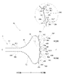
- perforations for forming the outlet are arranged in an elongated annular shape extending in the longitudinal direction by a die-cutting technique such as die-cutting, so that the outlet has a substantially elliptical shape. It has been practiced to have a width in the depth direction as shown in Patent Documents 1 and 2 below. Furthermore, in recent years, in order to further improve the ease of taking out, the outlet has been made into a substantially gourd-shaped shape with widened ends in the width direction.
- tearing of the perforation 150 is smooth and continuous at this end, particularly in the vicinity of the perforation 150e at the end of 105B.
- an unintended tear 105P may occur at the end of the outlet 106.
- the outlet forming portion 105 formed by annularly arranging the perforations 150 as the end portion in the width direction is widened in the depth direction Y, the range of the perforations becomes closer to the direction orthogonal to the tear-off direction. Being longer, this tearing is more likely to occur. Therefore, the approximately gourd-shaped outlet forming portion with widened ends is likely to cause the tear 105P.
- the packaging film is a uniaxially stretched film stretched in a direction Y perpendicular to the longitudinal direction X of the outlet forming portion 105, such a tear 105P is more likely to occur.
- the longitudinal direction (MD direction) of the packaging film is generally parallel to the longitudinal direction of the outlet forming part. is likely to occur.
- the main object of the present invention is to improve the opening property by preventing the widthwise edge of the outlet from being torn when unsealed, and to improve the drawing property of sanitary thin paper, especially hard sanitary thin paper such as paper towels. To provide an excellent packaging body for film packaging.
- the first means is A packaging body in which a bundle of sanitary thin paper is wrapped with a flexible resin packaging film, Having an outlet forming portion formed by arranging an easy-cleavage line in a ring on the upper surface, The easy-cleavage line forming the edge of at least one end in the width direction of the outlet-forming portion, At one end or both ends of the main cut portion, a dogleg-shaped end cut portion is connected at an angle of 90° or more, and the modified cut portion has perforations arranged through the non-cut portion, The end cut portion and the end portion of the adjacent modified cut portion where the end cut portion is not provided overlap at least one of the outer side and the center side in the width direction of the outlet forming portion.
- the deformed cut portion located on the outer side in the width direction of the outlet forming portion is positioned more outward in the width direction of the outlet forming portion.
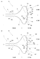
- the second means is The outlet forming portion includes a narrow portion extending in the width direction at the central portion in the depth direction, and a widened portion continuously extending from the end portion of the narrow portion toward the outside in the width direction and gradually widening as it separates from the narrow portion. and a curved convex portion that is continuous with the widened portion and bulges outward in the width direction,
- the package according to the first means, wherein the portion forming the edge of at least one curved convex portion of the easy-cleavage line has perforations in which deformed cut portions and non-cut portions are alternately arranged. is.
- a third way is The packaging body according to the second means, wherein 80% or more of the area forming the edge of the curved convex portion is perforations in which the deformed cut portion and the non-cut portion are alternately arranged.
- a fourth means is The package according to the second means, wherein the length of the curved protrusion in the depth direction is 25 to 45 mm, and the length of the protrusion in the width direction is 2.5 to 12.5 mm.
- a fifth means is The outlet forming portion has a width direction length of 70% or more of the width direction length of the upper surface of the bundle, and a maximum length in the depth direction of 10 to 40% of the depth direction length of the upper surface of the bundle.
- the length in the width direction of the narrow part is 50 to 70% of the length in the width direction of the upper surface of the bundle, and the length in the depth direction is 0.5 of the length in the depth direction of the upper surface of the bundle
- a film packaging package which is excellent in unsealability because the edge in the width direction of the outlet is difficult to tear when unsealed, and which is excellent in pulling out sanitary thin paper, particularly hard sanitary thin paper such as paper towels. be.
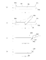
- FIG. 3 is a perspective view for explaining a bundle of sanitary thin paper; It is a top view for demonstrating an outlet formation part. It is a perspective view for demonstrating the usage condition of the package which concerns on this invention. It is a partially enlarged view for explaining an outlet forming portion. It is a figure for demonstrating the other example of an outlet formation part. It is a figure for demonstrating another example of a shape of an outlet formation part.
- FIG. 11 is a diagram for explaining another example of the outlet forming portion; It is a figure for demonstrating the conventional outlet formation part.
- FIGS. 1 to 8 are embodiments of the present invention. It should be noted that directions such as up-down direction and left-right direction in the present invention and this specification are changed depending on the orientation of the package, and do not mean the absolute direction of the space. Further, rigidity is sometimes referred to as stiffness, rigidity, and stiffness of paper.
- a packaging body 1 according to the present invention is a bundle 3 of sanitary thin paper sheets 2 such as paper towels folded and stacked, and wrapped in a flexible packaging film 4.
- An outlet forming portion 5 is provided on an upper surface 4C. have.
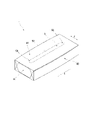
- the package 1 has a top surface 4C, a bottom surface 4D facing the top surface 4C, and long and short sides 4B and 4A positioned between the top surface 4C and the bottom surface 4D so as to approximate the shape of the bundle 3. It has a substantially hexahedral shape.
- This gusset packaging is a pillow packaging with a gusset, in which a bundle 3 as an object to be packaged is wrapped in a cylindrical shape so that openings are formed at both ends in the longitudinal direction with a packaging film 4, and the bundles are overlapped in the winding direction.
- the portion 4X to be connected is adhered by fusion processing or an adhesive at the bottom position of the bundle 3, etc., and the edge of the portion extending beyond the short side surface 3A of the bundle 3 is fusion-bonded from the top and bottom while forming a gusset.
- the short side surface 4A is used as a sealing surface by bonding with an adhesive agent.
- the sealing surface which is the short side surface 4A
- the long side surface 4B which is the gusset
- the packaging form of the package 1 is not limited.
- a simple pillow packaging without a gusset may be used, and other suitable packaging forms such as overlap packaging, also called caramel packaging, in which short sides 4A are overlapped and fused together as shown in FIG. can be
- the bundle 3 of sanitary thin paper 2 contained in the package 1 according to the present invention is a so-called pop-up bundle. As shown particularly in FIG. 2, this bundle 3 is such that the rectangular sanitary thin paper 2 is folded in two, and the folded pieces 2B of the other sanitary thin papers 2 located above and below are positioned on the folded inner side 2A.
- a plurality of sanitary thin paper sheets 2 are folded and laminated, and has a pair of longitudinal side surfaces 3B where the folding edges 2C of each sanitary thin paper sheet 2 are arranged, a pair of short side surfaces 3A where the folding edges 2C are not arranged, and further the short side surfaces. It has a substantially rectangular parallelepiped shape having a pair of flat surfaces (upper and lower surfaces) 3C that are connected to 3A and longitudinal side surfaces 3B.
- the number of sets of sanitary thin paper 2 constituting the bundle 3 is not limited, but can be 30 to 240 sets with one ply or multiple plies as one set.
- the size of the bundle 3 is also not limited, but a bundle of 200 sets of sanitary thin paper is preferably 30 to 100 mm in height x 150 to 250 mm in the longitudinal direction (width) x 100 to 130 mm in the lateral direction (depth). . Further, when the height of the bundle is shorter than the length of the upper surface of the bundle in the depth direction, the pop-up failure improvement effect of the present invention is enhanced.
- the filling rate of the bundle 3 in the package 1 is not limited as long as it does not interfere with the effects of the present invention, but the gap between the bundle and the packaging film is preferably in the range of 0 to 30 mm.
- the bundle 3 may be wrapped in a slightly compressed state in the vertical direction with the wrapping film.
- Each of the sanitary thin papers 2 constituting the bundle 3 has a single-layer structure of one sheet or a laminated structure of a plurality of sheets.
- the number of plies is not limited, it is preferable to use one layer (1 ply) or two layers (2 plies).
- the basis weight per ply is not limited, it is preferably 10 to 40 g/m 2 . Desirably, the mass per set is 1.0 to 2.5 g.
- the sanitary thin paper with one or two plies of sheets having the above basis weight is particularly suitable for paper towels suitable for wiping hands after washing hands. Furthermore, it is desirable that the thickness of one set of this sanitary thin paper is 100 to 500 ⁇ m.
- Sanitary thin paper with such a number of plies, a basis weight, and a paper thickness can be hygienically processed at the time of pop-up due to the configuration of the present invention, particularly the shape of the characteristic outlet forming portion having a narrow width portion, a widened portion, and a curved convex portion. It is highly effective in improving pop-up defects in which the thin paper falls without being pulled up, and erection defects in which the package does not stand up and falls down.
- the basis weight is based on the measurement method of JIS P 8124 (1998).
- the thickness of the paper was determined by fully conditioning the test piece under the conditions of JIS P 8111 (1998), and then using a dial thickness gauge (thickness measuring instrument) "PEACOCK G type" (manufactured by Ozaki Seisakusho Co., Ltd.) under the same conditions. and the value measured in the state of multiple plies using an equivalent machine.
- the sanitary thin paper 2 according to the present invention is a dry type, not a so-called wet type impregnated with a chemical solution. Therefore, the bundle 3 formed by the sanitary thin paper 2 contains a lot of air.
- a chemical solution such as a moisturizing component that increases moisture by absorbing moisture such as polyol represented by glycerin is added. good too.
- the raw material pulp constituting the sanitary thin paper 2 is not limited.
- a mixture of softwood-derived pulp such as NBKP and hardwood-derived pulp such as LBKP may be mentioned.
- waste paper pulp may be blended, or waste paper pulp may be used alone.
- the softwood-derived pulp is more than 50% in order to exhibit particularly excellent effects in sanitary thin papers such as paper towels that have strong stiffness and high rigidity.
- dry tensile strength of the sanitary tissue paper 2 is not limited, those having a longitudinal direction of 1000-3000 cN/25 mm and a lateral direction of 250-1500 cN/25 mm are particularly suitable for the present invention. Dry tensile strength is measured according to JIS P8113 (1998). Examples of measuring devices include Minebea Co., Ltd.'s "Universal Tensile Compression Tester TG-200N" and its equivalent.
- the outlet forming part 5 is formed by annularly arranging an easy tear line 50 on the upper surface 4C facing the uppermost sanitary thin paper 2 of the bundle 3 of the packaging film 4 .
- annular in this specification does not mean that the shape is limited to a circular shape or an elliptical shape, but means a shape in which a closed region is formed.
- Such an outlet forming portion 5 tears the easy-cleavage line 50, separates and removes the range surrounded by the easy-cleavage line 50, and draws out the sanitary thin paper 2 to the upper surface 4C of the package 1.
- An outlet 6, which is an opening of the is formed.
- the bundle 3 is of a pop-up type, when one sheet of sanitary thin paper 2 at the top of the bundle 3 is pulled out from the formed outlet, the next sanitary sheet located immediately below it is pulled out. A part of the thin paper comes to be exposed from the outlet.
- the outlet forming portion 5 has the easy-cleavage lines 50 arranged in a ring, the outlet 6 formed by separating and removing the range surrounded by the easy-cleavage lines 50 is formed only in a straight line. It does not have a slit shape, but has a certain width in the depth direction.
- Such outlet-forming portion 5 is formed by tearing off a range surrounded by easy-cleavage line 50 so as to continuously pull from one end portion 5A toward the other end portion 5B. Since the film in the range of can be separated and removed, it is excellent in operability at the time of opening.
- the end located on the left side of the drawing is described as one end 5A, and the end located on the right side is described as the other end 5B. These can be replaced.
- the package 1 of the form shown in FIGS. 1 to 5 has a substantially gourd-shaped outlet forming part 5, which is a particularly preferable shape.
- the outlet forming portion 5 includes a narrow portion 51 extending in the width direction at the central portion in the depth direction of the upper surface 4C, and an end portion of the narrow portion 51 extending outward in the width direction of the bundle 3. It has a widened portion 52 that gradually widens with increasing distance from the narrow portion 51 and a curved convex portion 53 that is continuous with the widened portion 52 and bulges outward in the width direction of the bundle 3 .
- the widened portion 52 is arranged so that the easy tearing line 50 gradually increases in angle with respect to the width direction toward the outside in the width direction of the bundle 3 .
- the easy-cleavage line 50 forming the edge of the widened portion 52 preferably has a taper angle ⁇ of 25 to 60 degrees with respect to the width direction.
- the easy-cleavage line 50 is formed in a curved line and connected smoothly from the widened portion 52 to the curved convex portion 53 .
- the easy-cleavage line 50 is arranged in this way, the easy-cleavage line 50 is easily cleaved smoothly from the widened portion 52 toward the curved convex portion 53 .
- the outlet 6 formed by the outlet forming portion 5 has a substantially trapezoidal shape in which the vicinity of the edge extending from the narrow portion 51 to the widened portion 52 is easily movable in the vertical direction. Therefore, as shown in FIG. 4, when a set of sanitary thin paper sheets 2 is pulled out from the stack 3, the edge strips 51A are deformed so as to be slightly rolled up in the direction in which they are pulled out. , the next exposed set of sanitary thin paper 2 is leaned against and supported.
- the outlet 6 formed by the outlet forming portion 5 is such that the base portion 2R of the next sanitary thin paper, which is partially exposed from the outlet 6 following the sanitary thin paper pulled out from the bundle 3, is formed by the edge of the curved convex portion 53. It deforms so as to be wound along 6E, and easily deforms into a highly upright columnar shape. Furthermore, since the recessed portion 6H is formed between the widened portion 52 and the curved convex portion 53 of the outlet forming portion 5 when the outlet 6 is formed, the base of the next sanitary thin paper partly exposed from the outlet 6 is formed. By fitting the portion 2R into the recessed portion 6H, the erectability is enhanced.
- the outlet forming portion 5 the pop-up failure due to the depression of the inside of the packaging film of the sanitary thin paper, which is likely to occur when the rigidity of the sanitary thin paper is high, is less likely to occur.
- This action and effect is particularly effective in combination with the sanitary thin paper having the suitable basis weight and paper thickness as well as the suitable packaging film described later.
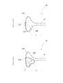
- the outlet forming portion 5 according to the present invention may have a shape that does not have the widened portion 52 as shown in FIG.
- the outlet-forming portion 5 may have a linear easy-cleavage line connected to the ring-shaped easy-cleavage line within a range that does not interfere with the effects of the present invention.
- the length L1 is 70% or more of the length L2 in the width direction of the upper surface of the bundle 3, and the maximum length L3 in the depth direction of the entire outlet forming portion 5 is 10% or more of the length L4 in the depth direction of the upper surface of the bundle 3.
- the length L5 in the width direction of the narrow portion is 50 to 70% of the length L2 in the width direction of the upper surface of the bundle 3
- the length L6 in the depth direction of the narrow portion is the length of the bundle 3 is preferably 0.5 to 10% of the length L4 in the depth direction of the upper surface of the .
- Such a shape of the outlet forming portion 5 is such that a curved convex portion 53 that is wide especially in the depth direction is formed.
- the free edge piece 51A formed near the edge of the narrow portion 51 becomes wider and larger, so that the space between the narrow portions 51 can be widened when pulled out. Therefore, when the sanitary thin paper 2 is pulled out from the bundle 3, it can be taken out smoothly.
- the sanitary thin paper 2 to be used is a highly rigid sanitary thin paper 2 such as a paper towel with the above basis weight and paper thickness, and the upper surface position of the package 1 is likely to be deformed when the sanitary thin paper 2 is pulled out, when the sanitary thin paper 2 is pulled out
- the entire upper surface is less likely to be distorted and is easily maintained flat, and when the sanitary thin paper 2 is to be taken out one by one, it is particularly stable and easy to take out.
- the substantially trapezoidal free edge piece 51A formed near the edge of the narrow portion 51 is wider and larger, and the deep recessed portion 6H is formed. Since the edge piece can be firmly supported and the base portion 2R of the sanitary thin paper 2 is supported, it is effectively prevented from falling.
- the length of the edge of the curved convex portion 53 is increased, the sanitary thin paper 2 is gently wound along the edge of the curved convex portion 53. As a result, it becomes more orthostatic.
- the length L3 of the curved convex portion 53 in the depth direction is specifically 25 to 45 mm, and the bulging length L7 in the width direction is 2.5 to 12.5 mm.
- the flexible resin-made packaging film 4 constituting the exterior of the package 1 include polyethylene film, polypropylene film, polyester film, polyethylene terephthalate film, nylon film, vinylidene chloride film, and ethylene vinyl alcohol.
- examples include monolayer films of copolymers, appropriately laminated laminate films containing these films, and gas barrier films obtained by subjecting these films to surface treatment such as aluminum vapor deposition.
- Biomass films derived from plant materials such as sugarcane, potato (starch), and corn can also be used. The use of such biomass films is desirable from the viewpoint of environmental protection.
- Polypropylene film and polyethylene film are particularly suitable.
- the packaging film 4 may be a satin-finished film that is excellent in design and touch.
- the melting point of the film is preferably 150° C. or lower. The lower the melting point of the packaging film, the lower the heat-sealing treatment can be performed, but the practical lower limit is 80°C.
- Examples of polypropylene films include unstretched polypropylene films (CPP), and examples of polyethylene films include linear low-density polyethylene films (LLDPE), low-density polyethylene films (LDPE), and medium-density polyethylene films (MDPE).
- ethylene vinyl alcohol copolymer resin film and polyethylene terephthalate resin film which have excellent fragrance retention properties, are desirable for packaging scented tissue paper and other scented items. Even if it is a multi-layer resin film in which a polyethylene resin film or a polypropylene resin film is laminated on one or both sides of an ethylene vinyl alcohol copolymer resin film or a polyethylene terephthalate resin film to enhance the heat-sealing property. good.
- the outlet forming portion 5 has at least one edge in the width direction of the outlet forming portion 5 (the other end 5B in the illustrated example).
- the modified cut portion 50D includes a modified cut portion 50D 1 having a doglegged end cut portion 50e at one end and a doglegged end cut portion 50e formed at both ends. It can be a modified cut portion 50D 2 that has a shape, and these may be mixed. As shown in FIGS.
- the modified cut portion 50D having a dogleg-shaped end cut portion 50e at one end may be used alone.
- a mode in which a cut portion 50C having no end cut portion 50e is arranged between perforations in which the modified cut portions 50D are arranged via the non-cut portion 50U. can also be
- the deformed cut portion 50D and the non-cut portion 50U are arranged alternately.
- the entire range may be composed of easy-cleavage lines in which deformable cut portions 50D and non-cut portions 50U are alternately arranged.
- 5 and 6 illustrate a form in which the portion forming the edge of the curved convex portion 53 has a portion 50P in which the deformed cut portion 50D and the non-cut portion 50U are alternately arranged.
- the present invention is not limited to this, and as shown in FIG. They may be arranged alternately.
- the end cut portion 50e of the modified cut portion 50D includes a first cut portion 50e 1 following the main cut portion 50m and a second cut portion 50e 1 following the first cut portion 50e 1 , as particularly shown in FIG. 50e 2 , which are connected at an angle ⁇ of 90° or more to form a dogleg shape.
- a part of the end cut portion 50e is provided with the end cut portion of the adjacent modified cut portion.
- the end portion 50t is arranged to overlap at least one of the outer side and the central side in the width direction of the outlet forming portion 5, and an end cut portion 50e and an end cut portion are provided.
- the deformed cut portion 50D located on the outer side in the width direction of the outlet forming portion 5 overlaps with the end portion 50t that is not cut so that it is positioned on the outer side in the width direction of the outlet forming portion 5. , are configured to overlap.
- the end cut portions 50e are arranged so as to overlap only on the outer side of the outlet forming portion 5 in the width direction. It is not necessary to be positioned further outward, and as in the form shown in FIG. Alternatively, as shown in FIG. 6(a), the end cut portion 50e overlaps the outer side of the outlet forming portion 5 in the width direction and the central side of the outlet forming portion 5 in the width direction. They may be mixed with overlapping ones. In the present invention, instead of the end cut portion 50e, the deformed cut portion 50D positioned on the outer side in the width direction of the outlet forming portion 5 may be overlapped so as to be on the outer side.
- the cut portion 50C without the end cut portion 50e overlaps with the end cut portion 50e.
- the portion 50C is positioned further outward in the width direction of the outlet forming portion 5 than the adjacent deformed cut portion 50D, the end of the cut portion 50C that does not have the end cut portion 50e is located at the deformed cut portion 50D. It is preferable that they are overlapped so as to be on the outer side in the width direction of the outlet forming portion 5 from the end cut portion 50e.
- the second cut portion 50e2 of the end cut portion 50e is preferably arranged substantially parallel to the main cut portion. Note that “substantially parallel” does not have to be completely parallel, and an error of approximately ⁇ 10° may be allowed.
- the outlet-forming portion 5 according to the present invention is finally cleaved in a general unsealing operation in which the range surrounded by the easy-cleavage line 50 is continuously pulled from the one end portion 5A toward the other end portion 5B.
- a portion 50P in which a deformed cut portion 50D and a non-cut portion 50U are alternately arranged is provided at the end portion in the width direction (the other end portion 5B in the illustrated example), which is the portion that is most likely to tear.
- the portion 50P in which the deformed cut portion 50D and the uncut portion 50U are alternately arranged generally, the area surrounded by the easy-cleavage line 50 is continuously pulled from the one end portion 5A toward the other end portion 5B.
- the end cut portion 50e and the end portion 50t where the end cut portion is not provided are overlapped in the adjacent deformed cut portion 50D. Since the deformed cut portion 50D located on the outer side in the width direction of the forming portion 5 overlaps with the outer side in the width direction of the outlet forming portion 5, the deformed cut portion 50D overlaps with the uncut portion 50U. , the end cut portion 50e that has already been cut exists at a position further outside in the width direction than the tip of the pulling direction.
- the end cut portion 50e is continuous with the main cut portion 50m at an angle of 90° or more, the cut is smoothly opened from the end cut portion 50e to the main cut portion 50m. Furthermore, if the angle between the first cut portion 50e 1 and the second cut portion 50e 2 is 90° or more, the cut opens more smoothly.
- a substantially gourd-shaped shape having a narrow portion 51, a widened portion 52, and a curved convex portion 53 as shown in FIGS.
- the range of the easy-cleavage line forming the edge portion of the curved convex portion 53 is long and is arranged along the depth direction, so that the pulling direction and the easy-cleavage line at the time of opening are different.
- the crossing angle with the tearing direction is large, and the shape is such that the packaging film 4 is likely to tear during the opening operation.
- the portion 50P in which the deformed cut portion 50D and the uncut portion 50U according to the present invention are alternately arranged at the end portion the risk of tearing is significantly reduced. It is particularly effective in packaging forms such as pillow packaging and gusset packaging, in which the longitudinal direction (MD direction) of the packaging film 4 is parallel to the longitudinal direction of the outlet forming portion 5 and tearing is likely to occur. be.
- the position of the end of the deformed cut portion 50D is shifted to the main cut portion by the end cut portion 50e. Since the position is slightly shifted inward or outward in the width direction from the extending direction of 50 m, when the outlet 6 is formed, the uncut portion 50U becomes slightly convex and has a serrated edge. For this reason, when drawing out a set of sanitary thin papers 2 from the bundle 3, the serrations are applied to the base portion 2R of the next set of sanitary thin papers 2, which is partially exposed from the take-out port following the taken out sanitary thin papers. The edge of the shape clamps the edge in the width direction of the sanitary thin paper 2 to enhance the prevention of falling.
- the deformed cut portion 50D is positioned on the width direction extension line of the center C in the depth direction of the narrow portion 51.
- a modified cut portion 50D2 having end cut portions 50e overlapping the outer side in the width direction at both ends of the modified cut portion.
- a deformed cut portion 50D 1 having an end cut portion 50e overlapping in the width direction only at the end portion positioned outward in the depth direction from the center C in the depth direction of the narrow portion 51 is formed.
- the deformed cut portion in a general unsealing operation in which the area surrounded by the easy tearing line 50 is continuously pulled from the one end portion 5A toward the other end portion 5B, the deformed cut portion
- the end cut portions 50e of the adjacent deformed cut portions 50D 1 and 50D 2 are present at positions on the outer side in the width direction that precede the ends of 50D 1 that do not have end cut portions in the tensile direction. Therefore, even if a minute tear occurs in the packaging film when the non-cut portion 50U therebetween is torn during the unsealing operation, the tear immediately follows the already torn end cut portion 50e. It is easy to tear, and it becomes difficult to proceed further.
- the length ratio of the modified cut portion 50D and the uncut portion 50U at the end of the outlet forming portion 5 is not necessarily limited, but the length L8 of the modified cut portion 50D is not limited, but is preferably 5 mm or more and 20 mm or less. is preferably 7 mm or more and 13 mm or less.
- the length L9 of the first cut portion 50e 1 and the second cut portion 50e 2 of the end cut portion 50e need not be the same, but is 0.2 mm or more and 3.0 mm or less, preferably 0.5 mm or more. 0.5 mm or less is desirable.
- the length L11 of the uncut portion 50U between the deformed cut portions 50D is 0.2 mm or more and 3.0 mm or less, preferably 0.3 mm or more and 2.0 mm or less.
- the overlap width L12 between the end cut portion 50e and the end portion of the adjacent modified cut portion where the end cut portion is not provided is not necessarily limited, but is 0.2 mm or more and 3.0 mm or less, preferably 0.2 mm or more. It is desirable to be 3 mm or more and 2.0 mm or less. In these ranges, tearing is extremely difficult to occur between the deformed cut portions 50D, and the non-cut portions 50U are cut, so that tearing progresses continuously and smoothly.
- the angle ⁇ between the main cut portion 50m and the first cut portion 50e 1 in the end cut portion 50e and the angle ⁇ between the first cut portion 50e 1 and the second cut portion 50e 2 are Although they do not have to be the same, they are preferably in the range of 90° or more. It is preferably in the range of 100° or more, more preferably 120° or more. In addition, it is desirable that the main cut portion 50m and the first cut portion 50e 1 and the first cut portion 50e 1 and the second cut portion 50e 2 are chamfered, and they are the same.
- the curvature is not limited, but R0.1 to R2.0 is preferable, R0.2 to 1.2 is more preferable, and R0.4 to 1.1 is particularly preferable. . With this curvature, the opening of the deformed cut portion proceeds smoothly from the main cut portion 50m to the end cut portion 50e or from the end cut portion 50e to the main cut portion 50m.
- the portions 50P in which the deformed cut portions 50D and the uncut portions 50U are alternately arranged are located at both ends of the outlet-forming portion 5. It can also be at one end only. If it is formed only on one side, the opposite end is, for example, as shown in FIG.
- the range L10 up to the crossing position can be made a continuous cut portion.
- a free piece 5T is formed in a range from one depth side to the outer side end at one end 5A of the outlet forming portion 5, and the free piece 5T is formed. It becomes easier to pick up and roll up, and the opening operation becomes easier.
- the thickness of the packaging film 4 may be selected as appropriate, but the thickness measured according to JIS P 8118 (1998) is preferably 20 to 75 ⁇ m. If the thickness is 20 to 75 ⁇ m, the effects of the present invention can be exhibited particularly effectively.
- dial thickness gauge thickness measuring instrument
- PACOCK G-1A type manufactured by Ozaki Seisakusho Co., Ltd.
- the portions other than the portion where the deformed cut portion 50D and the uncut portion 50U are alternately arranged are perforations and uncut portions (non-cut portions).
- a slit cut or the like provided with a cut portion) can be used. However, it is not limited to this.
- the type of perforation is not limited as long as the portion other than the portion aligned through the deformed cut portion 50D and the non-cut portion 50U is used as the perforation.
- Examples include normal perforations in which the cut portion 50C is a straight line, micro perforations in which the cut portion is a hole, and zipper perforations in which the shape of the cut portion is Y-shaped, substantially L-shaped, or ⁇ -shaped. Preferred are normal perforations.
- a slit cut is a portion obtained by cutting a film into a slit shape, and by having a non-cut portion, the non-cut portion and the cut portion are arranged alternately.
- a slit cut having a non-cut portion may be simply referred to as a slit cut.
- a slit cut having perforations and a non-cut portion may not be distinguished, but in the present invention, a slit cut is a normal linear cut portion that has two normal straight cut portions, except for a unique shape such as the deformed cut portion 50D. It is called a slit cut when it is less than the pitch, that is, when two normal cuts of the same length are not consecutive. In general, the slit cut is formed so that the length of the cut portion is longer than the perforations.
- the cut tie ratio of the slit cut having perforations and non-cut portions in portions other than the portions where the deformed cut portions 50D and the non-cut portions 50U are alternately arranged is an appropriate interval depending on the ease of tearing of the film used.
- the length of the cut part is 0.8 mm or more and 20.0 mm or less
- the length of the uncut part (tie part or uncut part) is appropriately from the range of 0.3 mm or more and 5.0 mm or less.
- part or all of the uncut portion 50U of the easy tear line 50 according to the present invention faces the bundle 3 from the surface side, which is the surface that does not face the bundle 3, in the thickness direction of the packaging film 4. It is possible to form a half-cut portion that is cut to a predetermined depth range in the thickness direction, although it is not completely cut down to the back side, which is the side to be cut.
- the uncut portion 50U By making the uncut portion 50U into a half-cut portion with a notch, the force required for tearing the packaging film 4 is reduced, and the tearing of the easy-cleavage lines 50 facilitates continuous and smooth tearing.
- the end portion of the outlet forming portion 5, particularly the non-cut portion 50U between the deformed cut portions 50D located in the curved convex portion 53, may be a half-cut portion.
- the depth of the cut in the half-cut portion is not limited, but is preferably 20% or more and 80% or less of the thickness of the packaging film.
- the non-cut portion is configured with perforations that are not half-cut portions.
- the edge of the narrow portion 51 is less likely to tear unintentionally.
- the slit cut having perforations and non-cut portions including the portions where the cut portions 50C and the half-cut portions are alternately arranged, is formed at once by die cutting, for example. be able to.
- Examples 1 to 4 of the present invention and Comparative Examples 1 and 2 were produced, and tests were conducted on the sinking of the sanitary thin paper and the tearing of the unsealing outlet.
- the shape of the outlet forming portion of the package according to Examples 1 to 4 and Comparative Example 1 is a substantially gourd shape having a narrow portion, a wide portion, and a curved convex portion shown in FIGS. 1 to 5. .
- the outlet forming portion of the package according to Comparative Example 2 is a simple linear perforation.
- a bundle of 1-ply paper towels (trade name: Raku La Cook Kitchen Paper, basis weight: 20 g/m 2 , paper thickness: 220 ⁇ m) was folded up in a pop-up manner.
- the packaging form according to each example is gusset packaging, and the stretching direction of the packaging film is a direction orthogonal to the width direction of the outlet forming portion.
- the easy tearing line related to the outlet forming part is cleaved to form an outlet, and the paper towels constituting the bundle are pulled out from the outlet in order up to the last one. , counted the number of times the drop actually occurred.
- Table 1 shows the dimensions of the outlet forming part, the ratio of the length in the depth direction and the length in the width direction of the upper surface of the bundle, and the test results in each example.
- Examples 1 to 4 in which a deformed cut portion and a non-cut portion are alternately arranged in the portion that constitutes the edge of the end portion (curved convex portion), have the maximum length in the depth direction of the outlet.
- the length in the depth direction of the curved convex portion, which is the end portion is as long as 35 mm, and the range is 30% of the depth direction of the upper surface of the bundle, making it easy to tear. , There was no confirmed tear at the end of the outlet.
- Example 1 the cut portion of the curved convex portion in Example 1 was not a deformed cut portion but a conventional general cut portion without an end cut portion. , a tear occurred at the end of the outlet. Even if it is an easy-cleavage line that forms the edge of a very long curved convex portion as in the example, the portion should be alternately arranged with deformed cut portions and non-cut portions. showed that tearing at the edge of the outlet was prevented during the opening operation.
- the number of depressions was confirmed to be 12 in Comparative Example 2, in which the outlet forming portion is a single perforation and the outlet is a slit.
- the number of drops was 0 and no drop could be confirmed.
- the ejection port having the shape of the ejection port forming portion having the narrow portion, the widened portion, and the curved convex portion is particularly excellent in preventing sagging.
- the package according to the present invention has excellent opening properties because the edge in the width direction of the outlet is difficult to tear when opened, and is also excellent in drawing out sanitary thin paper, especially hard sanitary thin paper such as paper towels. It is a packaging body of film packaging.
- L1 length in the width direction (longitudinal direction) of the outlet forming portion
- L2 length in the width direction (longitudinal direction) of the upper surface of the bundle
- L3 maximum length in the depth direction (lateral direction) of the outlet forming portion
- L4 length of the upper surface of the bundle in the depth direction (transverse direction)
- L5 length of the narrow portion in the width direction (longitudinal direction)
- L6 length of the narrow portion in the depth direction (transverse direction)
- L7 Range up to the position exceeding the outer side end of the convex portion
- L11 length of the non-cut portion between the modified cut portions
- L12 ... overlap width of the edge portion of the adjacent modified cut portion where the end cut portion is not provided .
- Outlet forming part 105A... One end of the outlet forming part, 105B... The other end of the outlet forming part, 105P... Film tear, 150... Perforation, 150e... Perforation at the end in the width direction, X : longitudinal direction (width direction), Y: direction perpendicular to the longitudinal direction (depth direction), Z: thickness direction of the packaging film, C: center of the narrow portion in the depth direction.
Abstract
[Problem] To provide a film packaging body for sanitary tissue paper sheets and that has superior openability. [Solution] The above problem is solved by this packaging body having packaged therein a bundle of sanitary tissue paper sheets in a packaging film made of soft resin. Said packaging body has, on a top surface thereof, a takeout port formation part that is formed by annularly providing an easily-tearable open line. A portion of the easily-tearable open line that constitutes an edge of at least one end of the takeout port formation part in the width direction is formed by perforations in which deformed cut sections having a dog-legged end-cut portion joined to one end or both ends of a main cut portion at an angle of 90° or more are arranged with non-cut portions therebetween. Said end-cut portion and an end of another adjacent deformed cut section having no end-cut portion are configured to overlap each other at a position on the outer side and/or center side of the takeout port formation part in the width direction, and the overlap between said end-cut portion and the end having no end-cut portion is configured such that the deformed cut section located on the outer side in the width direction of the takeout port formation part is located on the further outer side in the width direction of the takeout port formation part.
Description
本発明は、ペーパータオルなどの衛生薄葉紙を折り畳み積み重ねた束を柔軟な包装フィルムで包装した包装体に関する。
The present invention relates to a package in which a bundle of folded sanitary thin paper such as paper towels is wrapped in a flexible packaging film.
ペーパータオルやフェイシャルティシューなどの衛生薄葉紙の包装形態として、1枚又は複数プライを折り畳み積み重ね、最上位のシートを摘まんで引き出すと次のシートの一部が引き出されるいわゆるポップアップ式の束としたものを、樹脂製の柔軟な包装フィルムによって包装する形態が知られている。
As a packaging form of sanitary thin paper such as paper towels and facial tissues, a so-called pop-up type bundle in which one or more plies are folded and stacked, and when the top sheet is picked and pulled out, a part of the next sheet is pulled out. A form of packaging with a resin-made flexible packaging film is known.
旧来、このような衛生薄葉紙の包装体は、取出口形成用のミシン目を簡易な直線状のミシン目とし、上面にスリット状の取出口が形成されるようにしたものが一般的であった。しかし、スリット状の取出口は、スリット長を長くすると、内部に残存するシート枚数が少なくなった際にシートが内部に落ち込んでしまう問題があり、また、スリット長を短くすると、開封後の最初に一枚のシートをフィルム外へ引き出し難く、また、使用初期や使用末期に引き出し抵抗が高くなりすぎて、シート引き出し時に包装フィルムごと、持ち上がってしまいポップアップできなくなることがあるという問題があった。
In the past, such sanitary thin paper packages generally used simple linear perforations for forming the outlet and formed a slit-shaped outlet on the top surface. . However, if the slit length is long, the slit-shaped outlet has a problem that the sheets will fall inside when the number of sheets remaining inside is reduced. In addition, it is difficult to pull out a single sheet from the film, and the pull-out resistance becomes too high at the beginning and end of use, and when the sheet is pulled out, the packaging film may be lifted up and cannot be popped up.
そこで、このスリット状の取出口の問題を改善すべく、ダイカット等の型抜き技術により取出口を形成するためのミシン目を長手方向に延在する細長環状に配し、略楕円形状の取出口のように奥行方向に幅のあるものとすることが行われている(下記、特許文献1及び2)。さらには、近年では、より取出性を改善すべく、取出口を幅方向の端部を拡幅した略瓢箪型形状とすることも行われている。
Therefore, in order to solve the problem of the slit-shaped outlet, perforations for forming the outlet are arranged in an elongated annular shape extending in the longitudinal direction by a die-cutting technique such as die-cutting, so that the outlet has a substantially elliptical shape. It has been practiced to have a width in the depth direction as shown in Patent Documents 1 and 2 below. Furthermore, in recent years, in order to further improve the ease of taking out, the outlet has been made into a substantially gourd-shaped shape with widened ends in the width direction.
しかし、従来の略楕円形状や略瓢箪型形状の取出口は、柔らかさやしなやかさが重視され、洟をかむ用途や食事の際の口周りの清拭などフェイシャル用途が主であるフェイシャルティシュペーパーのような衛生薄葉紙を主たる対象として設計されており、顔以外の肌の清拭や、物品の清拭用途にも使用しやすいように「厚手でしっかりとした、破れにくい品質」のティシュペーパーや、フェイシャルティシュペーパーと比較してより剛性の高い、主に手洗い後の手拭きに使用されるペーパータオルのような衛生薄葉紙には必ずしも適してはいなかった。
However, conventional approximately oval or approximately gourd-shaped outlets emphasize softness and suppleness. It is designed mainly for sanitary tissue paper such as this, and it is easy to use for wiping the skin other than the face and wiping items. It is not always suitable for sanitary tissue papers such as paper towels, which are mainly used for wiping hands after washing hands, which are stiffer than facial tissue papers.
このような衛生薄葉紙の取り出し性を良好にするには取出口を奥行方向により幅広に形成することが考えられるが、剛性の高い衛生薄葉紙は、紙質の相違から柔らかさやしなやかさに優れるフェイシャルティシュペーパーと同様に設計することが難しく、単に取出口の奥行方向を幅広にすると、ポップアップ時に次の衛生薄葉紙が引きあがらず落ち込むポップアップ不良や、包装体上面に起立しないで倒伏してしまう起立不良が非常に生じやすくなってしまう。
In order to improve the ease of taking out such sanitary thin paper, it is conceivable to form a wider outlet in the depth direction. It is difficult to design the same way as , and if the depth direction of the outlet is simply widened, the pop-up failure in which the next sanitary thin paper does not pull up when it pops up, and the rise failure in which the package falls down instead of standing up on the top surface of the package. It becomes easy to occur in.
他方で、例えば、図9(a)に示す略楕円形状の取出口形成部のように、ダイカット等の型抜き技術によりミシン目150を環状に配して形成した取出口形成部105では、図9(b)のように長手方向Xの一方端部105Aから他方端部105Bに向かってこの環状ミシン目内範囲105Zを切剥がすことで簡易に取出口を形成できる利点がある。しかし、このような開封操作をすると他方端部105Bでは最後に切り離される他方端のミシン目150eに近づくにつれて、ミシン目150が裂開していく方向が、環状ミシン目内範囲105Zが引っ張られる方向に対して直交する方向に近くなっていくため、図9(c)に示すように、この端部、特に105Bの端のミシン目150eの近傍においてミシン目150の裂開がスムーズに連続的に行われず、図9(d)に示すように取出口106の端部に意図しない裂け105Pが発生してしまうことがあった。ミシン目150を環状に配して形成した取出口形成部105では、幅方向の端部が奥行方向Yに拡幅されるにつれて、切剥がし方向に対して直交する方向に近くなるミシン目の範囲がより長くなるため、この裂けが発生しやすくなる。したがって、端部が拡幅された略瓢箪型形状の取出口形成部などは、裂け105Pが発生しやくなる。
On the other hand, for example, like the substantially elliptical outlet forming portion shown in FIG. As shown in 9(b), there is an advantage that an extraction port can be easily formed by cutting off the annular perforated area 105Z from one end 105A in the longitudinal direction X toward the other end 105B. However, when such an unsealing operation is performed, the direction in which the perforation 150 is torn as it approaches the perforation 150e at the other end, which is cut off last at the other end 105B, is the direction in which the annular perforation inner area 105Z is pulled. Therefore, as shown in FIG. 9(c), tearing of the perforation 150 is smooth and continuous at this end, particularly in the vicinity of the perforation 150e at the end of 105B. As shown in FIG. 9(d), an unintended tear 105P may occur at the end of the outlet 106. As shown in FIG. In the outlet forming portion 105 formed by annularly arranging the perforations 150, as the end portion in the width direction is widened in the depth direction Y, the range of the perforations becomes closer to the direction orthogonal to the tear-off direction. Being longer, this tearing is more likely to occur. Therefore, the approximately gourd-shaped outlet forming portion with widened ends is likely to cause the tear 105P.
さらに、特に包装フィルムが、取出口形成部105の長手方向Xと直交する方向Yに延伸されている一軸延伸フィルムの場合に、このような裂け105Pがより発生しやすい。また、ピロー包装やガセット包装の形態の包装体は、包装フィルムの縦方向(MD方向)が、取出口形成部の長手方向と平行する方向となるものが一般的であるため、このような裂けが発生しやすい。
Furthermore, especially when the packaging film is a uniaxially stretched film stretched in a direction Y perpendicular to the longitudinal direction X of the outlet forming portion 105, such a tear 105P is more likely to occur. In addition, in the case of pillow packaging and gusset packaging, the longitudinal direction (MD direction) of the packaging film is generally parallel to the longitudinal direction of the outlet forming part. is likely to occur.
そこで、本発明の主たる課題は、上記の問題に鑑みて、開封時に取出口の幅方向の縁が裂け難く開封性に優れ、さらに、衛生薄葉紙、特にペーパータオルのような硬い衛生薄葉紙の引き出し性に優れる、フィルム包装の包装体を提供することにある。
Therefore, in view of the above-mentioned problems, the main object of the present invention is to improve the opening property by preventing the widthwise edge of the outlet from being torn when unsealed, and to improve the drawing property of sanitary thin paper, especially hard sanitary thin paper such as paper towels. To provide an excellent packaging body for film packaging.
上記課題を解決するための手段は次のとおりである。
その第一の手段は、
衛生薄葉紙の束が柔軟な樹脂製の包装フィルムによって包装されている包装体であり、
上面に易裂開線を環状に配して形成された取出口形成部を有し、
取出口形成部の幅方向の少なくとも一方の端部の縁を構成する易裂開線は、
主カット部の一方端又は両端に、く字型の端カット部が、90°以上の角度を有して連接されている変形カット部が、非カット部を介して並ぶミシン目を有し、
その端カット部と隣接する他の変形カット部の端カット部が設けられていない端部とが、取出口形成部の幅方向の外方側及び中央側の少なくとも一方側の位置で重なるように、配され、かつ、
端カット部と端カット部が設けられていない端部との重なりは、取出口形成部の幅方向の外方側に位置する変形カット部のほうが、取出口形成部の幅方向のより外方側となるようにして、重なっている、
ことを特徴とする包装体である。 Means for solving the above problems are as follows.
The first means is
A packaging body in which a bundle of sanitary thin paper is wrapped with a flexible resin packaging film,
Having an outlet forming portion formed by arranging an easy-cleavage line in a ring on the upper surface,
The easy-cleavage line forming the edge of at least one end in the width direction of the outlet-forming portion,
At one end or both ends of the main cut portion, a dogleg-shaped end cut portion is connected at an angle of 90° or more, and the modified cut portion has perforations arranged through the non-cut portion,
The end cut portion and the end portion of the adjacent modified cut portion where the end cut portion is not provided overlap at least one of the outer side and the center side in the width direction of the outlet forming portion. , and
As for the overlap between the end cut portion and the end portion where the end cut portion is not provided, the deformed cut portion located on the outer side in the width direction of the outlet forming portion is positioned more outward in the width direction of the outlet forming portion. side by side, overlapping
A package characterized by:
第二の手段は、
取出口形成部は、奥行方向中央部において幅方向に延在する幅狭部と、この幅狭部の端部に連続して幅方向外方に向かって幅狭部より離れるにつれて漸次広くなる拡幅部と、この拡幅部に連続して幅方向外方に向かって凸に膨出する湾曲凸部と、を有する形状をなし、
易裂開線の少なくとも一方の湾曲凸部の縁を構成する部分が、変形カット部と非カット部とが交互に配されたミシン目を有している、上記第一の手段に係る包装体である。 The second means is
The outlet forming portion includes a narrow portion extending in the width direction at the central portion in the depth direction, and a widened portion continuously extending from the end portion of the narrow portion toward the outside in the width direction and gradually widening as it separates from the narrow portion. and a curved convex portion that is continuous with the widened portion and bulges outward in the width direction,
The package according to the first means, wherein the portion forming the edge of at least one curved convex portion of the easy-cleavage line has perforations in which deformed cut portions and non-cut portions are alternately arranged. is.
第三の手段は、
湾曲凸部の縁を構成する部分の80%以上の範囲が、前記変形カット部と非カット部とが交互に配されたミシン目である、上記第二の手段に係る包装体である。 A third way is
The packaging body according to the second means, wherein 80% or more of the area forming the edge of the curved convex portion is perforations in which the deformed cut portion and the non-cut portion are alternately arranged.
第四の手段は、
湾曲凸部の奥行方向の長さが25~45mm、幅方向の膨出長が2.5~12.5mmである、上記第二の手段に係る包装体である。 A fourth means is
The package according to the second means, wherein the length of the curved protrusion in the depth direction is 25 to 45 mm, and the length of the protrusion in the width direction is 2.5 to 12.5 mm.
湾曲凸部の奥行方向の長さが25~45mm、幅方向の膨出長が2.5~12.5mmである、上記第二の手段に係る包装体である。 A fourth means is
The package according to the second means, wherein the length of the curved protrusion in the depth direction is 25 to 45 mm, and the length of the protrusion in the width direction is 2.5 to 12.5 mm.
第五の手段は、
取出口形成部は、幅方向の長さが束の上面の幅方向の長さの70%以上であり、奥行方向の最大長さが束の上面の奥行方向の長さの10~40%であり、幅狭部の幅方向の長さが束の上面の幅方向の長さの50~70%であり、かつ、奥行方向の長さが束の上面の奥行方向の長さの0.5~10%である、上記第二~第四の手段に係る包装体である。 A fifth means is
The outlet forming portion has a width direction length of 70% or more of the width direction length of the upper surface of the bundle, and a maximum length in the depth direction of 10 to 40% of the depth direction length of the upper surface of the bundle. The length in the width direction of the narrow part is 50 to 70% of the length in the width direction of the upper surface of the bundle, and the length in the depth direction is 0.5 of the length in the depth direction of the upper surface of the bundle It is a package according to the above second to fourth means, wherein the content is up to 10%.
本発明によれば、開封時に取出口の幅方向の縁が裂け難く開封性に優れ、さらに、衛生薄葉紙、特にペーパータオルのような硬い衛生薄葉紙の引き出し性に優れる、フィルム包装の包装体が提供される。
ADVANTAGE OF THE INVENTION According to the present invention, there is provided a film packaging package which is excellent in unsealability because the edge in the width direction of the outlet is difficult to tear when unsealed, and which is excellent in pulling out sanitary thin paper, particularly hard sanitary thin paper such as paper towels. be.
以下、本発明の実施形態である図1~図8を参照しながら説明する。なお、本発明及び本明細書における上下方向、左右方向等の方向については、包装体の向きによって変更されるものであり、空間の絶対的な方向を意味するものではない。また、剛性とは、紙のコシ、剛度、こわさと言われることがある。
A description will be given below with reference to FIGS. 1 to 8, which are embodiments of the present invention. It should be noted that directions such as up-down direction and left-right direction in the present invention and this specification are changed depending on the orientation of the package, and do not mean the absolute direction of the space. Further, rigidity is sometimes referred to as stiffness, rigidity, and stiffness of paper.
本発明に係る包装体1は、ペーパータオル等の衛生薄葉紙2を折り畳み重ねた略直方体形状をなす束3を、柔軟性のある包装フィルム4によって包装したものであり、上面4Cに取出口形成部5を有している。この包装体1は、束3の形状に概ね近くなるように、上面4Cと、上面4Cに対面する下面4Dと、上面4C及び下面4Dの間に位置する長側面4B及び短側面4Aとを有する略六面体形状をなしている。
A packaging body 1 according to the present invention is a bundle 3 of sanitary thin paper sheets 2 such as paper towels folded and stacked, and wrapped in a flexible packaging film 4. An outlet forming portion 5 is provided on an upper surface 4C. have. The package 1 has a top surface 4C, a bottom surface 4D facing the top surface 4C, and long and short sides 4B and 4A positioned between the top surface 4C and the bottom surface 4D so as to approximate the shape of the bundle 3. It has a substantially hexahedral shape.
図1~図4には、ガセット包装の実施形態を示している。このガセット包装は、マチ付きのピロー包装であり、被包装物である束3を包装フィルム4で長手方向両端に開口が形成されるように筒型に巻き込むようにして包み、その巻き込み方向において重畳する部分4Xを束3底面位置等で融着処理や接着剤によって接着し、さらに束3の短手側面3Aを越えて延び出る部分の端縁を、マチを形成しつつ上下方向から融着処理や接着剤によって接着して、短側面4Aを封止面としたものである。このガセット包装では、この短側面4Aである封止面が束3の短手側面3Aに対面し、マチである長側面4Bが束3の折返面である長手側面3Bに対面する。但し、本発明においては、包装体1の包装形態は限定されるものではない。マチを有さない単なるピロー包装でもよく、図7に示すような、短側面4Aがフラップを重ねて融着されて構成される、キャラメル包装とも称されるオーバーラップ包装など適宜の他の包装形態とすることができる。
1 to 4 show embodiments of gusset packaging. This gusset packaging is a pillow packaging with a gusset, in which a bundle 3 as an object to be packaged is wrapped in a cylindrical shape so that openings are formed at both ends in the longitudinal direction with a packaging film 4, and the bundles are overlapped in the winding direction. The portion 4X to be connected is adhered by fusion processing or an adhesive at the bottom position of the bundle 3, etc., and the edge of the portion extending beyond the short side surface 3A of the bundle 3 is fusion-bonded from the top and bottom while forming a gusset. The short side surface 4A is used as a sealing surface by bonding with an adhesive agent. In this gusset packaging, the sealing surface, which is the short side surface 4A, faces the short side surface 3A of the bundle 3, and the long side surface 4B, which is the gusset, faces the long side surface 3B, which is the folding surface of the bundle 3. However, in the present invention, the packaging form of the package 1 is not limited. A simple pillow packaging without a gusset may be used, and other suitable packaging forms such as overlap packaging, also called caramel packaging, in which short sides 4A are overlapped and fused together as shown in FIG. can be
本発明に係る包装体1に内包される衛生薄葉紙2の束3は、いわゆるポップアップ式の束である。この束3は、特に図2に示すように、方形の衛生薄葉紙2が二つ折りされ、その折り返した内側2Aに上下に位置する他の衛生薄葉紙2の折り返した片2Bが位置するようにして、複数の衛生薄葉紙2が折り畳み積層されており、各衛生薄葉紙2の折り返し縁2Cが並ぶ一対の長手側面3Bと、折り返し縁2Cが並ばない一対の短手側面3Aとを有し、さらに短手側面3Aと長手側面3Bとに連接する一対の平面(上下面)3Cを有する略直方体形状をなす。
The bundle 3 of sanitary thin paper 2 contained in the package 1 according to the present invention is a so-called pop-up bundle. As shown particularly in FIG. 2, this bundle 3 is such that the rectangular sanitary thin paper 2 is folded in two, and the folded pieces 2B of the other sanitary thin papers 2 located above and below are positioned on the folded inner side 2A. A plurality of sanitary thin paper sheets 2 are folded and laminated, and has a pair of longitudinal side surfaces 3B where the folding edges 2C of each sanitary thin paper sheet 2 are arranged, a pair of short side surfaces 3A where the folding edges 2C are not arranged, and further the short side surfaces. It has a substantially rectangular parallelepiped shape having a pair of flat surfaces (upper and lower surfaces) 3C that are connected to 3A and longitudinal side surfaces 3B.
束3を構成する衛生薄葉紙2の組数は、限定されないが、1プライ又は複数プライを1組として30~240組とすることができる。束3の大きさも、限定されないが、衛生薄葉紙200組を束としたもので、高さ30~100mm×長手方向(幅)150~250mm×短手方向(奥行)100~130mmであるのが望ましい。また、束の高さが、束上面の奥行方向の長さよりも短いほうが、本発明のポップアップ不良の改善効果がより高まるものとなる。
The number of sets of sanitary thin paper 2 constituting the bundle 3 is not limited, but can be 30 to 240 sets with one ply or multiple plies as one set. The size of the bundle 3 is also not limited, but a bundle of 200 sets of sanitary thin paper is preferably 30 to 100 mm in height x 150 to 250 mm in the longitudinal direction (width) x 100 to 130 mm in the lateral direction (depth). . Further, when the height of the bundle is shorter than the length of the upper surface of the bundle in the depth direction, the pop-up failure improvement effect of the present invention is enhanced.
包装体1内における束3の充填率は、本発明の効果を妨げない範囲であれば、限定されないが、束と包装フィルムの隙間が、0~30mmの範囲にあるのが望ましい。束3が、包装フィルムによって上下方向において、やや圧縮された状態で包装されていてもよい。
The filling rate of the bundle 3 in the package 1 is not limited as long as it does not interfere with the effects of the present invention, but the gap between the bundle and the packaging film is preferably in the range of 0 to 30 mm. The bundle 3 may be wrapped in a slightly compressed state in the vertical direction with the wrapping film.
束3を構成する各衛生薄葉紙2は、シートが1枚の単層構造のもの又は複数枚重ねられた積層構造のものである。プライ数は限定されないが、1枚(1プライ)又は2枚重ね(2プライ)と言われるものが望ましい。1プライ当たりの坪量は、限定されないが10~40g/m2であるのが望ましい。1組あたりの質量は1.0~2.5gであるのが望ましい。前記坪量のシートを1プライ又は2プライとした衛生薄葉紙は、特に、手洗い後の手拭きに適するペーパータオルに好適である。さらに、この衛生薄葉紙の1組あたりの紙厚は100~500μmであるのが望ましい。このようなプライ数、坪量、紙厚の衛生薄葉紙は、本発明の構成、特に幅狭部、拡幅部、湾曲凸部を有する特徴的な取出口形成部の形状による、ポップアップ時に次の衛生薄葉紙が引きあがらず落ち込むポップアップ不良や、包装体上面に起立しないで倒伏してしまう起立不良の改善効果が高い。
Each of the sanitary thin papers 2 constituting the bundle 3 has a single-layer structure of one sheet or a laminated structure of a plurality of sheets. Although the number of plies is not limited, it is preferable to use one layer (1 ply) or two layers (2 plies). Although the basis weight per ply is not limited, it is preferably 10 to 40 g/m 2 . Desirably, the mass per set is 1.0 to 2.5 g. The sanitary thin paper with one or two plies of sheets having the above basis weight is particularly suitable for paper towels suitable for wiping hands after washing hands. Furthermore, it is desirable that the thickness of one set of this sanitary thin paper is 100 to 500 μm. Sanitary thin paper with such a number of plies, a basis weight, and a paper thickness can be hygienically processed at the time of pop-up due to the configuration of the present invention, particularly the shape of the characteristic outlet forming portion having a narrow width portion, a widened portion, and a curved convex portion. It is highly effective in improving pop-up defects in which the thin paper falls without being pulled up, and erection defects in which the package does not stand up and falls down.
なお、坪量は、JIS P 8124(1998)の測定方法による。1プライあたりの坪量の測定は、坪量=1組当たりのシート重量/(シート面積×プライ数)により算出することができる。また、紙厚は、試験片をJIS P 8111(1998)の条件下で十分に調湿した後、同条件下でダイヤルシックネスゲージ(厚み測定器)「PEACOCK G型」(株式会社尾崎製作所製)及びその相当機を用いて複数プライの状態で測定した値である。
The basis weight is based on the measurement method of JIS P 8124 (1998). The grammage per ply can be calculated by grammage=sheet weight per set/(sheet area×number of plies). In addition, the thickness of the paper was determined by fully conditioning the test piece under the conditions of JIS P 8111 (1998), and then using a dial thickness gauge (thickness measuring instrument) "PEACOCK G type" (manufactured by Ozaki Seisakusho Co., Ltd.) under the same conditions. and the value measured in the state of multiple plies using an equivalent machine.
また、本発明に係る衛生薄葉紙2は、乾燥されたドライタイプのものであり、薬液が含浸されている所謂ウェットタイプのものではない。したがって、衛生薄葉紙2により形成される上記の束3は多くの空気を含むものである。このドライタイプの衛生薄葉紙2においても、グリセリンに代表されるポリオール等の吸湿によって水分を高める保湿成分等の薬液が付与されている薬液付与タイプのものがあるが、このような衛生薄葉紙であってもよい。
Also, the sanitary thin paper 2 according to the present invention is a dry type, not a so-called wet type impregnated with a chemical solution. Therefore, the bundle 3 formed by the sanitary thin paper 2 contains a lot of air. Among the dry-type sanitary thin papers 2, there is also a chemical-imparted type in which a chemical solution such as a moisturizing component that increases moisture by absorbing moisture such as polyol represented by glycerin is added. good too.
衛生薄葉紙2を構成する原料パルプは限定されない。NBKP等の針葉樹由来のパルプとLBKP等の広葉樹由来のパルプとを配合したものが挙げられる。また、古紙パルプが配合されていてもよいし、古紙パルプのみからなるものであってもよい。本発明では、ペーパータオル等のコシの強く剛性の高い衛生薄葉紙において特に優れた効果を発現するため、特に針葉樹由来のパルプが50%超であるのがよい。
The raw material pulp constituting the sanitary thin paper 2 is not limited. A mixture of softwood-derived pulp such as NBKP and hardwood-derived pulp such as LBKP may be mentioned. In addition, waste paper pulp may be blended, or waste paper pulp may be used alone. In the present invention, it is preferable that the softwood-derived pulp is more than 50% in order to exhibit particularly excellent effects in sanitary thin papers such as paper towels that have strong stiffness and high rigidity.
衛生薄葉紙2の乾燥引張強度は、限定されないが、縦方向が1000~3000cN/25mm、横方向が250~1500cN/25mmであるものは、特に本発明に適する。乾燥引張強度の測定方法は、JIS P8113(1998)に準ずる方法で実施する。測定装置としては、ミネベア株式会社製「万能引張圧縮試験機 TG-200N」及びその相当機が挙げられる。
Although the dry tensile strength of the sanitary tissue paper 2 is not limited, those having a longitudinal direction of 1000-3000 cN/25 mm and a lateral direction of 250-1500 cN/25 mm are particularly suitable for the present invention. Dry tensile strength is measured according to JIS P8113 (1998). Examples of measuring devices include Minebea Co., Ltd.'s "Universal Tensile Compression Tester TG-200N" and its equivalent.
取出口形成部5は、包装フィルム4の束3の最上位の衛生薄葉紙2に対面する上面4Cに易裂開線50を環状に配して形成される。なお、本明細書における環状とは、円形状や楕円形状に限定される意味ではなく、閉じた領域が形成される形状という意味である。このような取出口形成部5は、易裂開線50を裂開し、その易裂開線50で囲まれる範囲を分離除去することにより、包装体1の上面4Cに衛生薄葉紙2を引き出すための開口部である取出口6が形成される。本発明に係る包装体1では、束3がポップアップ式となっているため、形成された取出口から束3の最上位の衛生薄葉紙2を一枚引き出すと、その直近下方に位置する次の衛生薄葉紙の一部が取出口より露出されるようになる。また、この取出口形成部5は、易裂開線50を環状に配していることから、易裂開線50で囲まれる範囲を分離除去して形成される取出口6は、直線のみのスリット形状ではなく、奥行方向にある程度の幅を有するものとなる。このような取出口形成部5は、易裂開線50で囲まれる範囲を一方端部5Aから他方端部5Bに向かって連続的に引っ張るように切剥がすことで、その取出口形成部5内の範囲のフィルムを分離除去できるため開封時の操作性に優れる。なお、本明細書では、図面上左側に位置する端部を一方端部5Aと、右側に位置する端部を他方端部5Bとして説明するが、説明の便宜のために定めただけであり、これらは入れ替えることができる。
The outlet forming part 5 is formed by annularly arranging an easy tear line 50 on the upper surface 4C facing the uppermost sanitary thin paper 2 of the bundle 3 of the packaging film 4 . Note that the term “annular” in this specification does not mean that the shape is limited to a circular shape or an elliptical shape, but means a shape in which a closed region is formed. Such an outlet forming portion 5 tears the easy-cleavage line 50, separates and removes the range surrounded by the easy-cleavage line 50, and draws out the sanitary thin paper 2 to the upper surface 4C of the package 1. An outlet 6, which is an opening of the is formed. In the packaging body 1 according to the present invention, since the bundle 3 is of a pop-up type, when one sheet of sanitary thin paper 2 at the top of the bundle 3 is pulled out from the formed outlet, the next sanitary sheet located immediately below it is pulled out. A part of the thin paper comes to be exposed from the outlet. In addition, since the outlet forming portion 5 has the easy-cleavage lines 50 arranged in a ring, the outlet 6 formed by separating and removing the range surrounded by the easy-cleavage lines 50 is formed only in a straight line. It does not have a slit shape, but has a certain width in the depth direction. Such outlet-forming portion 5 is formed by tearing off a range surrounded by easy-cleavage line 50 so as to continuously pull from one end portion 5A toward the other end portion 5B. Since the film in the range of can be separated and removed, it is excellent in operability at the time of opening. In this specification, the end located on the left side of the drawing is described as one end 5A, and the end located on the right side is described as the other end 5B. These can be replaced.
図1~図5に示す形態の包装体1は、特に好ましい形状である略瓢箪型形状の取出口形成部5を有するものを示している。この取出口形成部5は、上面4Cの奥行方向中央部において幅方向に延在する幅狭部51と、この幅狭部51の端部に連続して束3の幅方向外方に向かって幅狭部51より離れるにつれて漸次広くなる拡幅部52と、この拡幅部52に連続して束3の幅方向外方に向かって凸に膨出する湾曲凸部53と、を有している。
The package 1 of the form shown in FIGS. 1 to 5 has a substantially gourd-shaped outlet forming part 5, which is a particularly preferable shape. The outlet forming portion 5 includes a narrow portion 51 extending in the width direction at the central portion in the depth direction of the upper surface 4C, and an end portion of the narrow portion 51 extending outward in the width direction of the bundle 3. It has a widened portion 52 that gradually widens with increasing distance from the narrow portion 51 and a curved convex portion 53 that is continuous with the widened portion 52 and bulges outward in the width direction of the bundle 3 .
拡幅部52は、特に、易裂開線50が幅方向に対して束3の幅方向外方に向かって漸次角度が大きくなるように配されているのが望ましい。拡幅部52の縁となる易裂開線50は、幅方向に対するテーパー角∠αは25~60度であるのが望ましい。
It is particularly desirable that the widened portion 52 is arranged so that the easy tearing line 50 gradually increases in angle with respect to the width direction toward the outside in the width direction of the bundle 3 . The easy-cleavage line 50 forming the edge of the widened portion 52 preferably has a taper angle ∠α of 25 to 60 degrees with respect to the width direction.
また、拡幅部52から湾曲凸部53にかけては、易裂開線50が曲線に形成され滑らかにつながっているのが望ましい。このように易裂開線50が配されていると、拡幅部52から湾曲凸部53に向かって易裂開線50がスムーズに裂開しやすくなる。
In addition, it is desirable that the easy-cleavage line 50 is formed in a curved line and connected smoothly from the widened portion 52 to the curved convex portion 53 . When the easy-cleavage line 50 is arranged in this way, the easy-cleavage line 50 is easily cleaved smoothly from the widened portion 52 toward the curved convex portion 53 .
この図1~図5に示される実施形態では、取出口形成部5により形成される取出口6は、上記幅狭部51から拡幅部52にかかる縁の近傍が上下方向に動きやすい略台形状の自由な縁片51Aとなるため、特に図4に示されるように、束3から一組の衛生薄葉紙2を引き出す際には、その縁片51Aが引き出される方向にやや捲れるように変形し、次の露出する一組の衛生薄葉紙2に対しては凭れて支持するようになる。また、この取出口形成部5による取出口6は、束3から引き出された衛生薄葉紙に続く、取出口6から一部が露出する次の衛生薄葉紙の根本部分2Rが、湾曲凸部53の縁6Eに沿って巻かれるように変形し、起立性の高い柱状に変形しやくなる。さらに、取出口形成部5の拡幅部52と湾曲凸部53との間は、取出口6とした際に窪み部6Hとなるため、取出口6から一部が露出する次の衛生薄葉紙の根本部分2Rがこの窪み部6Hに嵌るようにして、起立性が高まるようにもなる。特に、この取出口形成部5では、衛生薄葉紙の剛性が高いと生じやすいとされる衛生薄葉紙の包装フィルム内部の落ち込みによるポップアップ不良が、上記の作用によって生じ難いものとなる。なお、この作用効果は、特に上記の好適な坪量、紙厚の衛生薄葉紙、さらには後述の好適な包装フィルムとの組み合わせにおいて効果的である。但し、本発明に係る取出口形成部5は、図7に示すように、拡幅部52を有さない形状であってもよい。また、取出口形成部5は、本発明の作用効果を妨げない範囲で、環状に配された易裂開線に接続する直線状の易裂開線が存在するものであってもよい。
In the embodiment shown in FIGS. 1 to 5, the outlet 6 formed by the outlet forming portion 5 has a substantially trapezoidal shape in which the vicinity of the edge extending from the narrow portion 51 to the widened portion 52 is easily movable in the vertical direction. Therefore, as shown in FIG. 4, when a set of sanitary thin paper sheets 2 is pulled out from the stack 3, the edge strips 51A are deformed so as to be slightly rolled up in the direction in which they are pulled out. , the next exposed set of sanitary thin paper 2 is leaned against and supported. In addition, the outlet 6 formed by the outlet forming portion 5 is such that the base portion 2R of the next sanitary thin paper, which is partially exposed from the outlet 6 following the sanitary thin paper pulled out from the bundle 3, is formed by the edge of the curved convex portion 53. It deforms so as to be wound along 6E, and easily deforms into a highly upright columnar shape. Furthermore, since the recessed portion 6H is formed between the widened portion 52 and the curved convex portion 53 of the outlet forming portion 5 when the outlet 6 is formed, the base of the next sanitary thin paper partly exposed from the outlet 6 is formed. By fitting the portion 2R into the recessed portion 6H, the erectability is enhanced. In particular, in the outlet forming portion 5, the pop-up failure due to the depression of the inside of the packaging film of the sanitary thin paper, which is likely to occur when the rigidity of the sanitary thin paper is high, is less likely to occur. This action and effect is particularly effective in combination with the sanitary thin paper having the suitable basis weight and paper thickness as well as the suitable packaging film described later. However, the outlet forming portion 5 according to the present invention may have a shape that does not have the widened portion 52 as shown in FIG. In addition, the outlet-forming portion 5 may have a linear easy-cleavage line connected to the ring-shaped easy-cleavage line within a range that does not interfere with the effects of the present invention.
また、図1~図5に示すような、幅狭部51、拡幅部52及び湾曲凸部53を有する取出口形成部5の形状においては、特に、取出口形成部5全体の幅方向の長さL1が束3の上面の幅方向の長さL2の70%以上であり、取出口形成部5全体の奥行方向の最大長さL3が束3の上面の奥行方向の長さL4の10~40%であり、幅狭部の幅方向の長さL5が束3の上面の幅方向の長さL2の50~70%であり、かつ、幅狭部の奥行方向の長さL6が束3の上面の奥行方向の長さL4の0.5~10%であるのが望ましい。このような取出口形成部5の形状は、特に奥行き方向に広い湾曲凸部53が形成される。また、幅狭部51の縁近傍に形成される自由な縁片51Aがより広く大きいものとなり、引き出し時には幅狭部51の間が広く開くことが可能となる。このため、束3から衛生薄葉紙2を引き出す際にスムーズに取り出すことができる。特に、ガセット包装やピロー包装のような、短側面4Aと上面4Cとの境界に明確な折り線が形成され難く、包装体1の上面位置における包装フィルムが変形しやすい包装形態であったり、内包される衛生薄葉紙が上記の坪量及び紙厚のペーパータオル等の剛性の高い衛生薄葉紙2であり引き出し時に包装体1の上面位置を変形させやすいものであったりしても、衛生薄葉紙2の引き出し時に上面全体が歪みがたく平面に維持されやすく、衛生薄葉紙2を一枚ずつ取り出す際に特に安定して取り出しやすくなる。また、幅狭部51の縁近傍に形成される自由な略台形状の縁片51Aがより広く大きいものとなるとともに、深い窪み部6Hが形成されるため、剛性の高い衛生薄葉紙2に対しても縁片がしっかりと凭れるとともに、衛生薄葉紙2の根本部分2Rを支持するため落ち込みが効果的に防止される。また、湾曲凸部53の縁の長さが長くなるため、衛生薄葉紙2の湾曲凸部53の縁に沿って緩やかに巻かれるようになるが、剛性の高い衛生薄葉紙2では、コシ折れしがたいため、起立性がより高まるようになる。
Moreover, in the shape of the outlet forming portion 5 having the narrow portion 51, the widened portion 52, and the curved convex portion 53 as shown in FIGS. The length L1 is 70% or more of the length L2 in the width direction of the upper surface of the bundle 3, and the maximum length L3 in the depth direction of the entire outlet forming portion 5 is 10% or more of the length L4 in the depth direction of the upper surface of the bundle 3. 40%, the length L5 in the width direction of the narrow portion is 50 to 70% of the length L2 in the width direction of the upper surface of the bundle 3, and the length L6 in the depth direction of the narrow portion is the length of the bundle 3 is preferably 0.5 to 10% of the length L4 in the depth direction of the upper surface of the . Such a shape of the outlet forming portion 5 is such that a curved convex portion 53 that is wide especially in the depth direction is formed. In addition, the free edge piece 51A formed near the edge of the narrow portion 51 becomes wider and larger, so that the space between the narrow portions 51 can be widened when pulled out. Therefore, when the sanitary thin paper 2 is pulled out from the bundle 3, it can be taken out smoothly. In particular, it is difficult to form a clear folding line at the boundary between the short side 4A and the upper surface 4C, such as gusset packaging and pillow packaging, and the packaging film at the upper surface position of the package 1 is easily deformed. Even if the sanitary thin paper 2 to be used is a highly rigid sanitary thin paper 2 such as a paper towel with the above basis weight and paper thickness, and the upper surface position of the package 1 is likely to be deformed when the sanitary thin paper 2 is pulled out, when the sanitary thin paper 2 is pulled out The entire upper surface is less likely to be distorted and is easily maintained flat, and when the sanitary thin paper 2 is to be taken out one by one, it is particularly stable and easy to take out. In addition, the substantially trapezoidal free edge piece 51A formed near the edge of the narrow portion 51 is wider and larger, and the deep recessed portion 6H is formed. Since the edge piece can be firmly supported and the base portion 2R of the sanitary thin paper 2 is supported, it is effectively prevented from falling. In addition, since the length of the edge of the curved convex portion 53 is increased, the sanitary thin paper 2 is gently wound along the edge of the curved convex portion 53. As a result, it becomes more orthostatic.
なお、湾曲凸部53の奥行方向の長さL3は、具体的には25~45mm、幅方向の膨出長L7が2.5~12.5mmであるのが望ましい。
It is desirable that the length L3 of the curved convex portion 53 in the depth direction is specifically 25 to 45 mm, and the bulging length L7 in the width direction is 2.5 to 12.5 mm.
他方で、包装体1の外装を構成する柔軟性のある樹脂製の包装フィルム4の具体例としては、ポリエチレンフィルム、ポリプロピレンフィルム、ポリエステルフィルム、ポリエチレンテレフタレートフィルム、ナイロンフィルム、塩化ビニリデンフィルム、エチレンビニルアルコール共重合体の単層フィルム、または、それらのフィルムを含む適宜積層されたラミネートフィルムや、それらのフィルムにアルミ蒸着などの表面処理を施したガスバリアフィルムが例示できる。また、サトウキビ、芋(デンプン)、トウモロコシといった植物原料に由来するバイオマスフィルムを用いることもできる。このようなバイオマスフィルムの使用は、環境保護の観点から望ましい。
On the other hand, specific examples of the flexible resin-made packaging film 4 constituting the exterior of the package 1 include polyethylene film, polypropylene film, polyester film, polyethylene terephthalate film, nylon film, vinylidene chloride film, and ethylene vinyl alcohol. Examples include monolayer films of copolymers, appropriately laminated laminate films containing these films, and gas barrier films obtained by subjecting these films to surface treatment such as aluminum vapor deposition. Biomass films derived from plant materials such as sugarcane, potato (starch), and corn can also be used. The use of such biomass films is desirable from the viewpoint of environmental protection.
特にポリプロピレンフィルム、ポリエチレンフィルムが好適である。また、包装フィルム4は、意匠性や手触り性に優れる梨地フィルムであってもよい。フィルムの融点は150℃以下であるのがよい。なお、包装フィルムの融点が低いほうが低温で熱融着処理できるが、実質的な下限値は80℃である。ポリプロピレンフィルムとしては無延伸ポリプロピレンフィルム(CPP)、ポリエチレンフィルムとしては、直鎖低密度ポリエチレンフィルム(LLDPE)、低密度ポリエチレンフィルム(LDPE)、中密度ポリエチレンフィルム(MDPE)が挙げられる。
Polypropylene film and polyethylene film are particularly suitable. Moreover, the packaging film 4 may be a satin-finished film that is excellent in design and touch. The melting point of the film is preferably 150° C. or lower. The lower the melting point of the packaging film, the lower the heat-sealing treatment can be performed, but the practical lower limit is 80°C. Examples of polypropylene films include unstretched polypropylene films (CPP), and examples of polyethylene films include linear low-density polyethylene films (LLDPE), low-density polyethylene films (LDPE), and medium-density polyethylene films (MDPE).
さらに、香り付きのティシュペーパーなど匂いのあるものを包装するのであれば、保香性に優れるエチレンビニルアルコール共重合体樹脂フィルム、ポリエチレンテレフタレート樹脂フィルムが望ましい。エチレンビニルアルコール共重合体樹脂フィルム、ポリエチレンテレフタレート樹脂フィルムの一方面または両面に、ポリエチレン樹脂製フィルムやポリプロピレン樹脂製フィルムを積層して熱融着性が高められた複層の樹脂フィルムであってもよい。
Furthermore, ethylene vinyl alcohol copolymer resin film and polyethylene terephthalate resin film, which have excellent fragrance retention properties, are desirable for packaging scented tissue paper and other scented items. Even if it is a multi-layer resin film in which a polyethylene resin film or a polypropylene resin film is laminated on one or both sides of an ethylene vinyl alcohol copolymer resin film or a polyethylene terephthalate resin film to enhance the heat-sealing property. good.
ここで、本発明に係る取出口形成部5は、特に図5及び図6に示すように、取出口形成部5の幅方向の少なくとも一方の端部(図示例では他方端部5B)の縁となる部分に、易裂開線50が、主カット部50mの端に、く字型の端カット部50eが90°以上の角度を有して連接されている変形カット部50Dが、非カット部50Uを介して並ぶミシン目を有している。この変形カット部50Dは、図5において示すように、一方端のみく字型の端カット部50eが形成されている変形カット部50D1や、両端ともにく字型の端カット部50eが形成されている変形カット部50D2とすることができ、これらが混在していてよい。図6(a)及び図6(b)に示すように、一方端のみく字型の端カット部50eが形成されている変形カット部50Dのみで構成されていてもよい。さらに、特に、図6(b)に示すように、変形カット部50Dが、非カット部50Uを介して並ぶミシン目の間に、端カット部50eを有さないカット部50Cが配される形態とすることもできる。
5 and 6, the outlet forming portion 5 according to the present invention has at least one edge in the width direction of the outlet forming portion 5 (the other end 5B in the illustrated example). A deformed cut portion 50D in which the easy tear line 50 is connected to the end of the main cut portion 50m at an angle of 90 ° or more and a V-shaped end cut portion 50e is connected to the non-cut It has perforations aligned through the portion 50U. As shown in FIG. 5, the modified cut portion 50D includes a modified cut portion 50D 1 having a doglegged end cut portion 50e at one end and a doglegged end cut portion 50e formed at both ends. It can be a modified cut portion 50D 2 that has a shape, and these may be mixed. As shown in FIGS. 6(a) and 6(b), the modified cut portion 50D having a dogleg-shaped end cut portion 50e at one end may be used alone. Furthermore, in particular, as shown in FIG. 6B, a mode in which a cut portion 50C having no end cut portion 50e is arranged between perforations in which the modified cut portions 50D are arranged via the non-cut portion 50U. can also be
また、図1~図6に示す取出口形成部5の形状では、特に、湾曲凸部53の縁を構成する部分の80%以上の範囲が、前記変形カット部50Dと非カット部50Uとが交互に配された部分50Pとなっている。なお、この湾曲凸部53においては、好ましくは90%以上、特に好ましくは95%以上の範囲が、変形カット部50Dと非カット部50Uとが交互に配された部分50Pとなっているのがよい。全範囲が変形カット部50Dと非カット部50Uとが交互に配された易裂開線で構成されていてもよい。なお、図5及び図6は、湾曲凸部53の縁を構成する部分が、変形カット部50Dと非カット部50Uとが交互に配された部分50Pを有している形態を図示しているが、本発明は、これに限定されず、図7に示すように、単なる略楕円形状の取出口形成部5の端部の縁を構成する部分が変形カット部50Dと非カット部50Uとが交互に配されているものであってもよい。
In addition, in the shape of the outlet forming portion 5 shown in FIGS. 1 to 6, in particular, 80% or more of the portion constituting the edge of the curved convex portion 53 is the deformed cut portion 50D and the non-cut portion 50U. The portions 50P are arranged alternately. In this curved convex portion 53, preferably 90% or more, particularly preferably 95% or more, is a portion 50P in which the deformed cut portion 50D and the non-cut portion 50U are alternately arranged. good. The entire range may be composed of easy-cleavage lines in which deformable cut portions 50D and non-cut portions 50U are alternately arranged. 5 and 6 illustrate a form in which the portion forming the edge of the curved convex portion 53 has a portion 50P in which the deformed cut portion 50D and the non-cut portion 50U are alternately arranged. However, the present invention is not limited to this, and as shown in FIG. They may be arranged alternately.
変形カット部50Dにおける端カット部50eは、より具体的には、特に図5に示されるように、主カット部50mに続く第一カット部50e1と第一カット部50e1に続く第二カット部50e2とを有し、それらの間が90°以上の角度∠βをもって連接してく字型をなしている。
More specifically, the end cut portion 50e of the modified cut portion 50D includes a first cut portion 50e 1 following the main cut portion 50m and a second cut portion 50e 1 following the first cut portion 50e 1 , as particularly shown in FIG. 50e 2 , which are connected at an angle ∠β of 90° or more to form a dogleg shape.
さらに、変形カット部50Dと非カット部50Uとが交互に配された部分における変形カット部50Dの配列形態は、端カット部50eの一部が、隣接する変形カット部の端カット部が設けられていない端部50tに、取出口形成部5の幅方向の外方側及び中央側の少なくとも一方側の位置で、重なるように配されているとともに、端カット部50eと端カット部が設けられていない端部50tとの重なりが、取出口形成部5の幅方向の外方側に位置する変形カット部50Dのほうが、取出口形成部5の幅方向のより外方側となるようにして、重なっているように構成されている。図5は、端カット部50eが、取出口形成部5の幅方向外方側のみで重なるように配列されている例であるが、端カット部50eが必ずしも取出口形成部5の幅方向のより外方側に位置している必要はなく、図6(b)に示す形態のように、端カット部50eが、取出口形成部5の幅方向中央側のみで重なるように配列されていてもよいし、図6(a)に示されるように、端カット部50e端部が、取出口形成部5の幅方向外方側で重なるものと、取出口形成部5の幅方向中央側で重なるものとが混在していてもよい。本発明は端カット部50eではなく、取出口形成部5の幅方向の外方側に位置する変形カット部50Dが、外方側となるようにして重なっていればよい。なお、端カット部50eを有さないカット部50Cと端カット部50eとが重なる場合も同様であるのがよく、図6(b)に示されるように、端カット部50eを有さないカット部50Cがより、隣の変形カット部50Dよりも取出口形成部5の幅方向の外方側にある場合は、端カット部50eを有さないカット部50Cの端が、変形カット部50Dの端カット部50eより取出口形成部5の幅方向の外方側となるようにして重なるのがよい。
Furthermore, in the arrangement form of the modified cut portions 50D in the portion where the modified cut portions 50D and the non-cut portions 50U are alternately arranged, a part of the end cut portion 50e is provided with the end cut portion of the adjacent modified cut portion. The end portion 50t is arranged to overlap at least one of the outer side and the central side in the width direction of the outlet forming portion 5, and an end cut portion 50e and an end cut portion are provided. The deformed cut portion 50D located on the outer side in the width direction of the outlet forming portion 5 overlaps with the end portion 50t that is not cut so that it is positioned on the outer side in the width direction of the outlet forming portion 5. , are configured to overlap. FIG. 5 shows an example in which the end cut portions 50e are arranged so as to overlap only on the outer side of the outlet forming portion 5 in the width direction. It is not necessary to be positioned further outward, and as in the form shown in FIG. Alternatively, as shown in FIG. 6(a), the end cut portion 50e overlaps the outer side of the outlet forming portion 5 in the width direction and the central side of the outlet forming portion 5 in the width direction. They may be mixed with overlapping ones. In the present invention, instead of the end cut portion 50e, the deformed cut portion 50D positioned on the outer side in the width direction of the outlet forming portion 5 may be overlapped so as to be on the outer side. The same applies when the cut portion 50C without the end cut portion 50e overlaps with the end cut portion 50e. When the portion 50C is positioned further outward in the width direction of the outlet forming portion 5 than the adjacent deformed cut portion 50D, the end of the cut portion 50C that does not have the end cut portion 50e is located at the deformed cut portion 50D. It is preferable that they are overlapped so as to be on the outer side in the width direction of the outlet forming portion 5 from the end cut portion 50e.
また、端カット部50eにおける第二カット部50e2は、主カット部と実質的に平行に配されているのが好ましい。なお、実質的に平行とは完全に平行である必要はなく、概ね、±10°程度の誤差はあってもよい。
Also, the second cut portion 50e2 of the end cut portion 50e is preferably arranged substantially parallel to the main cut portion. Note that "substantially parallel" does not have to be completely parallel, and an error of approximately ±10° may be allowed.
本発明に係る取出口形成部5は、易裂開線50で囲まれる範囲の一方端部5Aから他方端部5Bに向かって連続的に引っ張る一般的な開封操作において、最後に裂開される最も裂けやすい部分である、幅方向の端部(図示例では他方端部5B)に、変形カット部50Dと非カット部50Uとが交互に配された部分50Pが設けられている。このような変形カット部50Dと非カット部50Uとが交互に配された部分50Pでは、易裂開線50で囲まれる範囲の一方端部5Aから他方端部5Bに向かって連続的に引っ張る一般的な開封操作をすると、他方端部5Bの縁においては、隣接する変形カット部50Dにおいて、端カット部50eと端カット部が設けられていない端部50tとが重なっており、特に、取出口形成部5の幅方向の外方側に位置する変形カット部50Dのほうが、取出口形成部5の幅方向のより外方側となるようにして、重なっているため、非カット部50Uよりも、引張方向の先のより幅方向外側の位置に、既に切断されている端カット部50eが、存在していることになり、係る開封操作時に変形カット部50Dの間にある非カット部50Uが裂開するときに、微小な包装フィルムの裂けが発生しても、その直後に裂けが既に裂開している隣の変形カット部50Dの端カット部50eに連続してそれ以上に裂けが進まないようになる。さらに、隣接する変形カット部50Dの端同士は、幅方向及び奥行方向のいずれにおいてもずれた位置となるため、易裂開線50で囲まれる範囲の一方端部5Aから他方端部5Bに向かって連続的に引っ張る一般的な開封操作をすると、これらの間の非カット部50Uは、切断直前でねじりが発生するためフィルムの裂けや伸び自体が発生し難くなる。このように、幅方向の端部(図示例では他方端部5B)に、本発明に係る変形カット部50Dと非カット部50Uとが交互に配された部分50Pを形成することで、開封しやすく開封時の裂けの発生のおそれが小さくなる。また、端カット部50eが90°以上の角度で主カット部50mに連続しているため端カット部50eから主カット部50mにスムーズにカットが開くようになる。さらに、第一カット部50e1と第二カット部50e2との間も90°以上の角度であればよりスムーズにカットが開く。
The outlet-forming portion 5 according to the present invention is finally cleaved in a general unsealing operation in which the range surrounded by the easy-cleavage line 50 is continuously pulled from the one end portion 5A toward the other end portion 5B. A portion 50P in which a deformed cut portion 50D and a non-cut portion 50U are alternately arranged is provided at the end portion in the width direction (the other end portion 5B in the illustrated example), which is the portion that is most likely to tear. In the portion 50P in which the deformed cut portion 50D and the uncut portion 50U are alternately arranged, generally, the area surrounded by the easy-cleavage line 50 is continuously pulled from the one end portion 5A toward the other end portion 5B. At the edge of the other end portion 5B, when an unsealing operation is performed, the end cut portion 50e and the end portion 50t where the end cut portion is not provided are overlapped in the adjacent deformed cut portion 50D. Since the deformed cut portion 50D located on the outer side in the width direction of the forming portion 5 overlaps with the outer side in the width direction of the outlet forming portion 5, the deformed cut portion 50D overlaps with the uncut portion 50U. , the end cut portion 50e that has already been cut exists at a position further outside in the width direction than the tip of the pulling direction. Even if a minute tear occurs in the packaging film when tearing, the tear continues to the end cut portion 50e of the adjacent deformed cut portion 50D that has already been torn immediately after that, and the tear progresses further. no more. Furthermore, since the ends of the adjacent deformed cut portions 50D are shifted in both the width direction and the depth direction, there is a If the uncut portion 50U between them is twisted immediately before cutting, the tearing or elongation of the film is less likely to occur. In this way, by forming a portion 50P in which the deformed cut portion 50D and the uncut portion 50U according to the present invention are alternately arranged at the end portion in the width direction (the other end portion 5B in the illustrated example), the package can be unsealed. It is easy to open and the risk of tearing when unsealing is reduced. Further, since the end cut portion 50e is continuous with the main cut portion 50m at an angle of 90° or more, the cut is smoothly opened from the end cut portion 50e to the main cut portion 50m. Furthermore, if the angle between the first cut portion 50e 1 and the second cut portion 50e 2 is 90° or more, the cut opens more smoothly.
また、特に、剛性の高いペーパータオル等の引出性等に優れる図1~図5に示すような幅狭部51、拡幅部52及び湾曲凸部53を有する略瓢箪型形状、さらに特に上記の好ましい数値範囲を有するものでは、湾曲凸部53の縁の部分を構成する易裂開線の範囲が長く、かつ、奥行き方向に沿うように配置されるため、開封時の引っ張り方向と易裂開線の裂開方向との交差角度が大きく、開封操作時の包装フィルム4の裂けが発生しやすい形状となる。しかし、その端部に本発明に係る変形カット部50Dと非カット部50Uとが交互に配される部分50Pを設けることで、裂けの発生のおそれが格段に小さくなる。ピロー包装やガセット包装のような、包装フィルム4の縦方向(MD方向)が、取出口形成部5の長手方向と平行する方向となるような裂けが発生しやすい包装形態では、特に効果的である。
In particular, a substantially gourd-shaped shape having a narrow portion 51, a widened portion 52, and a curved convex portion 53 as shown in FIGS. In the one having a range, the range of the easy-cleavage line forming the edge portion of the curved convex portion 53 is long and is arranged along the depth direction, so that the pulling direction and the easy-cleavage line at the time of opening are different. The crossing angle with the tearing direction is large, and the shape is such that the packaging film 4 is likely to tear during the opening operation. However, by providing the portion 50P in which the deformed cut portion 50D and the uncut portion 50U according to the present invention are alternately arranged at the end portion, the risk of tearing is significantly reduced. It is particularly effective in packaging forms such as pillow packaging and gusset packaging, in which the longitudinal direction (MD direction) of the packaging film 4 is parallel to the longitudinal direction of the outlet forming portion 5 and tearing is likely to occur. be.
また、本発明に係る取出口形成部5では、変形カット部50Dと非カット部50Uとが交互に配された部分50Pでは、変形カット部50Dの端の位置が端カット部50eによって主カット部50mの延在方向から幅方向内側又は幅方向外側にややずれた位置となるため、取出口6が形成されると非カット部50Uであった部分がやや凸となり鋸歯状の縁となる。このため束3から一組の衛生薄葉紙2を引き出す際には、取り出された衛生薄葉紙に続く、取出口から一部露出する次の一組の衛生薄葉紙2の根本部分2Rに対して、この鋸歯状の縁が衛生薄葉紙2の幅方向の縁を挟持し、落ち込みの防止性を高める。
In addition, in the outlet forming portion 5 according to the present invention, in the portion 50P in which the deformed cut portions 50D and the non-cut portions 50U are alternately arranged, the position of the end of the deformed cut portion 50D is shifted to the main cut portion by the end cut portion 50e. Since the position is slightly shifted inward or outward in the width direction from the extending direction of 50 m, when the outlet 6 is formed, the uncut portion 50U becomes slightly convex and has a serrated edge. For this reason, when drawing out a set of sanitary thin papers 2 from the bundle 3, the serrations are applied to the base portion 2R of the next set of sanitary thin papers 2, which is partially exposed from the take-out port following the taken out sanitary thin papers. The edge of the shape clamps the edge in the width direction of the sanitary thin paper 2 to enhance the prevention of falling.
ここで、特に好ましい本発明に係る取出口形成部5の形態は、図5に示すように幅狭部51の奥行方向の中央Cの幅方向延長線上に変形カット部50Dが位置しており、その変形カット部が両端部に幅方向外方で重なる端カット部50eを有する変形カット部50D2あるとともに、さらに、その変形カット部50D2より奥行方向外方に位置する変形カット部50Dが、幅狭部51の奥行方向の中央Cより奥行外方に位置する端部のみに幅方向外方で重なる端カット部50eを有する変形カット部50D1となっている形態である。この図5に示される取出口形成部5においても、易裂開線50で囲まれる範囲の一方端部5Aから他方端部5Bに向かって連続的に引っ張る一般的な開封操作において、変形カット部50D1の端カット部を有さない端よりも、引張方向において先行するより幅方向外側の位置に、隣接する変形カット部50D1,50D2の端カット部50eが、存在していることになるため、係る開封操作時にその間の非カット部50Uが裂開するときに、微小な包装フィルムの裂けが発生しても、その直後に裂けが既に裂開している端カット部50eに連続しやすく、それ以上に裂けが進み難くなる。
Here, as shown in FIG. 5, in a particularly preferable form of the outlet forming portion 5 according to the present invention, the deformed cut portion 50D is positioned on the width direction extension line of the center C in the depth direction of the narrow portion 51. There is a modified cut portion 50D2 having end cut portions 50e overlapping the outer side in the width direction at both ends of the modified cut portion. In this embodiment, a deformed cut portion 50D 1 having an end cut portion 50e overlapping in the width direction only at the end portion positioned outward in the depth direction from the center C in the depth direction of the narrow portion 51 is formed. In the outlet forming portion 5 shown in FIG. 5 as well, in a general unsealing operation in which the area surrounded by the easy tearing line 50 is continuously pulled from the one end portion 5A toward the other end portion 5B, the deformed cut portion The end cut portions 50e of the adjacent deformed cut portions 50D 1 and 50D 2 are present at positions on the outer side in the width direction that precede the ends of 50D 1 that do not have end cut portions in the tensile direction. Therefore, even if a minute tear occurs in the packaging film when the non-cut portion 50U therebetween is torn during the unsealing operation, the tear immediately follows the already torn end cut portion 50e. It is easy to tear, and it becomes difficult to proceed further.
取出口形成部5の端部の変形カット部50Dと非カット部50Uとの長さの比は、必ずしも限定されないが、変形カット部50Dの長さL8は、限定されないが5mm以上20mm以下、好ましくは7mm以上13mm以下が望ましい。また、端カット部50eにおける第一カット部50e1と第二カット部50e2の長さL9は、同一である必要はないが、0.2mm以上3.0mm以下、好ましくは0.5mm以上2.5mm以下であるのが望ましい。さらに、変形カット部50Dの間の非カット部50Uの長さL11は0.2mm以上3.0mm以下、好ましくは0.3mm以上2.0mm以下であるのが望ましい。
さらに、端カット部50eと、隣接する変形カット部の端カット部が設けられていない端部との重なり幅L12については、必ずしも限定されないが、0.2mm以上3.0mm以下、好ましくは0.3mm以上2.0mm以下であるのが望ましい。これらの範囲では、変形カット部50Dの間において裂けが極めて発生し難く非カット部50Uが切断されて、連続的にスムーズに裂開がより進みやすくなる。 The length ratio of the modifiedcut portion 50D and the uncut portion 50U at the end of the outlet forming portion 5 is not necessarily limited, but the length L8 of the modified cut portion 50D is not limited, but is preferably 5 mm or more and 20 mm or less. is preferably 7 mm or more and 13 mm or less. In addition, the length L9 of the first cut portion 50e 1 and the second cut portion 50e 2 of the end cut portion 50e need not be the same, but is 0.2 mm or more and 3.0 mm or less, preferably 0.5 mm or more. 0.5 mm or less is desirable. Furthermore, it is desirable that the length L11 of the uncut portion 50U between the deformed cut portions 50D is 0.2 mm or more and 3.0 mm or less, preferably 0.3 mm or more and 2.0 mm or less.
Furthermore, the overlap width L12 between the end cutportion 50e and the end portion of the adjacent modified cut portion where the end cut portion is not provided is not necessarily limited, but is 0.2 mm or more and 3.0 mm or less, preferably 0.2 mm or more. It is desirable to be 3 mm or more and 2.0 mm or less. In these ranges, tearing is extremely difficult to occur between the deformed cut portions 50D, and the non-cut portions 50U are cut, so that tearing progresses continuously and smoothly.
さらに、端カット部50eと、隣接する変形カット部の端カット部が設けられていない端部との重なり幅L12については、必ずしも限定されないが、0.2mm以上3.0mm以下、好ましくは0.3mm以上2.0mm以下であるのが望ましい。これらの範囲では、変形カット部50Dの間において裂けが極めて発生し難く非カット部50Uが切断されて、連続的にスムーズに裂開がより進みやすくなる。 The length ratio of the modified
Furthermore, the overlap width L12 between the end cut
また、端カット部50eにおける主カット部50mと第一カット部50e1との間の角度∠β、及び、第一カット部50e1と第二カット部50e2との間の角度∠γは、同一である必要はないが、ともに90°以上の範囲であるのがよい。好ましくは100°以上、より好ましくは120°以上の範囲にあるのがよい。また、主カット部50mと第一カット部50e1との間、及び、第一カット部50e1と第二カット部50e2との間は角取されているのが望ましく、それらが同一である必要はないが、その曲率については限定されないが、R0.1~R2.0がよく、より好ましくは、R0.2~1.2であり、特に好ましくは、R0.4~1.1である。この曲率であれば、主カット部50mから端カット部50eに向かって、又は、端カット部50eから主カット部50mに向かってスムーズに変形カット部の開きが進みやくなる。
Also, the angle ∠β between the main cut portion 50m and the first cut portion 50e 1 in the end cut portion 50e and the angle ∠γ between the first cut portion 50e 1 and the second cut portion 50e 2 are Although they do not have to be the same, they are preferably in the range of 90° or more. It is preferably in the range of 100° or more, more preferably 120° or more. In addition, it is desirable that the main cut portion 50m and the first cut portion 50e 1 and the first cut portion 50e 1 and the second cut portion 50e 2 are chamfered, and they are the same. Although not necessary, the curvature is not limited, but R0.1 to R2.0 is preferable, R0.2 to 1.2 is more preferable, and R0.4 to 1.1 is particularly preferable. . With this curvature, the opening of the deformed cut portion proceeds smoothly from the main cut portion 50m to the end cut portion 50e or from the end cut portion 50e to the main cut portion 50m.
なお、取出口形成部の縁を構成する易裂開線50において、変形カット部50Dと非カット部50Uとが交互に配される部分50Pは、取出口形成部5の両端部にあってもよく、また、一方端部のみにあってもよい。一方のみに形成するのであれば、反対の端部は、例えば、図8(a)に示すように、奥行き方向の一方側の拡幅部52Aの途中から湾曲凸部53Aの外方側端53tを超える位置までの範囲L10を連続するカット部とすることができる。このようにすると、図8(b)に示すように、取出口形成部5の一方端部5Aに一方の奥行側から外方側端を含む範囲に自由片5Tが形成され、その自由片5Tを摘まんで捲りやすくなり、開封操作がより行いやすくなる。
In addition, in the easy-cleavage line 50 constituting the edge of the outlet-forming portion, the portions 50P in which the deformed cut portions 50D and the uncut portions 50U are alternately arranged are located at both ends of the outlet-forming portion 5. It can also be at one end only. If it is formed only on one side, the opposite end is, for example, as shown in FIG. The range L10 up to the crossing position can be made a continuous cut portion. In this way, as shown in FIG. 8(b), a free piece 5T is formed in a range from one depth side to the outer side end at one end 5A of the outlet forming portion 5, and the free piece 5T is formed. It becomes easier to pick up and roll up, and the opening operation becomes easier.
ここで、包装フィルム4の厚さは、適宜に選択すればよいが、好ましくはJIS P 8118(1998)に準拠して測定される厚みが20~75μmであるのが望ましい。厚みが20~75μmあれば、特に、効果的に本発明の作用効果を発現させることができる。厚みは、測定試料をJIS P 8111(1998)の条件下で十分に調湿した後、ダイヤルシックネスゲージ(厚み測定器)「PEACOCK G-1A型」(株式会社尾崎製作所製)及びその相当機を用いて測定する。
Here, the thickness of the packaging film 4 may be selected as appropriate, but the thickness measured according to JIS P 8118 (1998) is preferably 20 to 75 μm. If the thickness is 20 to 75 μm, the effects of the present invention can be exhibited particularly effectively. For the thickness, after sufficiently conditioning the humidity of the measurement sample under the conditions of JIS P 8111 (1998), dial thickness gauge (thickness measuring instrument) "PEACOCK G-1A type" (manufactured by Ozaki Seisakusho Co., Ltd.) and its equivalent Measure using
本発明に係る取出口形成部5を構成する易裂開線50では、変形カット部50Dと非カット部50Uとが交互に配されている部分以外の部分は、ミシン目、アンカット部(非カット部)を設けたスリットカット等とすることができる。但しこれに限定されない。
In the easy tear line 50 constituting the outlet forming portion 5 according to the present invention, the portions other than the portion where the deformed cut portion 50D and the uncut portion 50U are alternately arranged are perforations and uncut portions (non-cut portions). A slit cut or the like provided with a cut portion) can be used. However, it is not limited to this.
変形カット部50Dと非カット部50Uを介して並ぶ部分以外の部分をミシン目とするのならば、その種類は限定されない。カット部50Cが直線である通常のミシン目、カット部が孔であるマイクロミシン目、カット部の形状がY字型、略L字型、<字型等のジッパーミシン目が例示できる。好ましくは、通常のミシン目である。スリットカットは、フィルムをスリット状にカットした部分であるが、非カット部を有することで、非カット部とカット部とが交互に並ぶものとなる。なお、非カット部を有するスリットカットを単にスリットカットと称する場合がある。ミシン目と非カット部を有するスリットカットは、区別されないこともあるが、本発明においては、スリットカットは、変形カット部50Dのような特異な形状を除き、通常の直線状のカット部が2ピッチ未満、つまり同じ長さの通常のカット部が二回連続しない場合にスリットカットと称している。一般的には、スリットカットは、ミシン目よりもカット部の長さが長く形成される。
The type of perforation is not limited as long as the portion other than the portion aligned through the deformed cut portion 50D and the non-cut portion 50U is used as the perforation. Examples include normal perforations in which the cut portion 50C is a straight line, micro perforations in which the cut portion is a hole, and zipper perforations in which the shape of the cut portion is Y-shaped, substantially L-shaped, or <-shaped. Preferred are normal perforations. A slit cut is a portion obtained by cutting a film into a slit shape, and by having a non-cut portion, the non-cut portion and the cut portion are arranged alternately. A slit cut having a non-cut portion may be simply referred to as a slit cut. A slit cut having perforations and a non-cut portion may not be distinguished, but in the present invention, a slit cut is a normal linear cut portion that has two normal straight cut portions, except for a unique shape such as the deformed cut portion 50D. It is called a slit cut when it is less than the pitch, that is, when two normal cuts of the same length are not consecutive. In general, the slit cut is formed so that the length of the cut portion is longer than the perforations.
変形カット部50Dと非カット部50Uとが交互に配されている部分以外の部分におけるミシン目や非カット部を有するスリットカットのカットタイ比は、用いるフィルムの破断のしやすさにより適宜の間隔に定めるが、カット部の長さとしては、0.8mm以上20.0mm以下、非カット部(タイ部又はアンカット部)の長さとしては、0.3mm以上5.0mm以下の範囲から適宜に設計するのがよい。
The cut tie ratio of the slit cut having perforations and non-cut portions in portions other than the portions where the deformed cut portions 50D and the non-cut portions 50U are alternately arranged is an appropriate interval depending on the ease of tearing of the film used. , the length of the cut part is 0.8 mm or more and 20.0 mm or less, and the length of the uncut part (tie part or uncut part) is appropriately from the range of 0.3 mm or more and 5.0 mm or less. should be designed to
なお、本発明に係る易裂開線50における非カット部50Uは、その一部又は全部において、包装フィルム4の厚み方向において、束3に対面しない側の面である表面側から束3に対面する側の面である裏面側に至るまで完全に切断されていないが、厚み方向の所定の深さ範囲まで切り込まれているハーフカット部とすることができる。非カット部50Uを、切込みを入れたハーフカット部とすることで、包装フィルム4が裂けるのに必要な力が小さくなり、易裂開線50の裂開が連続的にスムーズに進みやすくなる。取出口形成部5の端部、特に湾曲凸部53に位置する変形カット部50Dの間にある非カット部50Uがハーフカット部となっていてもよい。ハーフカット部における切込みの深さは限定されないが、包装フィルムの厚さの20%以上80%以下であるのが望ましい。
In addition, part or all of the uncut portion 50U of the easy tear line 50 according to the present invention faces the bundle 3 from the surface side, which is the surface that does not face the bundle 3, in the thickness direction of the packaging film 4. It is possible to form a half-cut portion that is cut to a predetermined depth range in the thickness direction, although it is not completely cut down to the back side, which is the side to be cut. By making the uncut portion 50U into a half-cut portion with a notch, the force required for tearing the packaging film 4 is reduced, and the tearing of the easy-cleavage lines 50 facilitates continuous and smooth tearing. The end portion of the outlet forming portion 5, particularly the non-cut portion 50U between the deformed cut portions 50D located in the curved convex portion 53, may be a half-cut portion. The depth of the cut in the half-cut portion is not limited, but is preferably 20% or more and 80% or less of the thickness of the packaging film.
また、図1~図5に示すような幅狭部51、拡幅部52及び湾曲凸部53を有する形状では、幅狭部51の縁の部分は、一方端部5Aから他方端部5Bに向かう開封操作時の引っ張り方向と、延存方向が一致するため、非カット部がハーフカット部となっていないミシン目で構成するのが望ましい。幅狭部51の縁が意図せず裂開し難くなる。
In addition, in the shape having the narrow portion 51, the widened portion 52, and the curved convex portion 53 as shown in FIGS. Since the pulling direction during the unsealing operation coincides with the extending direction, it is desirable that the non-cut portion is configured with perforations that are not half-cut portions. The edge of the narrow portion 51 is less likely to tear unintentionally.
なお、易裂開線50は、ミシン目と非カット部を有するスリットカットは、カット部50Cとハーフカット部とが交互に配される部分も含めて、例えば、ダイカットにより一回的に形成することができる。
In addition, the slit cut having perforations and non-cut portions, including the portions where the cut portions 50C and the half-cut portions are alternately arranged, is formed at once by die cutting, for example. be able to.
次いで、本発明の実施例1~4、比較例1~2を作製し、衛生薄葉紙の落ち込みと開封取出口の裂けについて試験を行った。実施例1~実施例4及び比較例1に係る包装体の取出口形成部の形状は、図1~5に示す幅狭部、拡幅部、湾曲凸部を有する略瓢箪型形状のものである。比較例2に係る包装体の取出口形成部は、単なる直線状のミシン目としたものである。
Next, Examples 1 to 4 of the present invention and Comparative Examples 1 and 2 were produced, and tests were conducted on the sinking of the sanitary thin paper and the tearing of the unsealing outlet. The shape of the outlet forming portion of the package according to Examples 1 to 4 and Comparative Example 1 is a substantially gourd shape having a narrow portion, a wide portion, and a curved convex portion shown in FIGS. 1 to 5. . The outlet forming portion of the package according to Comparative Example 2 is a simple linear perforation.
各例に係る包装体の内包される束は、1プライのペーパータオル(商品名ラクらクックキッチンペーパー、坪量20g/m2、紙厚220μm)を100組ポップアップ式に折り畳み重ねたものである。また、各例に係る包装形態は、ガセット包装であり、包装フィルムの延伸方向が取出口形成部の幅方向に直交する方向となっているものである。
A bundle of 1-ply paper towels (trade name: Raku La Cook Kitchen Paper, basis weight: 20 g/m 2 , paper thickness: 220 µm) was folded up in a pop-up manner. Moreover, the packaging form according to each example is gusset packaging, and the stretching direction of the packaging film is a direction orthogonal to the width direction of the outlet forming portion.
「落ち込み回数」の試験は、取出口形成部に係る易裂開線を裂開して、取出口を形成し、その取出口から束を構成するペーパータオルを最後の一枚まで順に引き出す操作を行い、実際に落ち込みが生じた回数をカウントした。
In the "number of times of depression" test, the easy tearing line related to the outlet forming part is cleaved to form an outlet, and the paper towels constituting the bundle are pulled out from the outlet in order up to the last one. , counted the number of times the drop actually occurred.
「開封性」は、各例に係る試料を被験者に、一方端部を摘まんで他方端に向かって引っ張るようにして開封する操作をさせ、取出口の他方端部に裂けが発生するか否かを評価することとした。N=10として、裂けが発生した例は「あり」、発生しない例は「なし」と評価した。
"Openability" was evaluated by having a subject pick up one end of each sample and pull it toward the other end to open the sample, and check whether or not the other end of the outlet is torn. was evaluated. With N=10, the cases where cracks occurred were evaluated as "yes", and the cases where they did not occur were evaluated as "no".
各例における取出口形成部の寸法や束上面の奥行方向長さや幅方向の長さに対する割合、及び試験の結果等は、下記表1に示す。
Table 1 below shows the dimensions of the outlet forming part, the ratio of the length in the depth direction and the length in the width direction of the upper surface of the bundle, and the test results in each example.

表1より、端部(湾曲凸部)の縁を構成する部分を変形カット部と非カット部とを交互に配したものとした実施例1~実施例4は、取出口の奥行方向最大長さ、つまり端部である湾曲凸部の奥行方向の長さが、35mmと長く、束上面の奥行方向の30%もの範囲となっており裂けやすい構成であるにもかかわらず、開封操作時において、取出口の端部の裂けが確認されたものがなかった。
From Table 1, Examples 1 to 4, in which a deformed cut portion and a non-cut portion are alternately arranged in the portion that constitutes the edge of the end portion (curved convex portion), have the maximum length in the depth direction of the outlet. In other words, the length in the depth direction of the curved convex portion, which is the end portion, is as long as 35 mm, and the range is 30% of the depth direction of the upper surface of the bundle, making it easy to tear. , There was no confirmed tear at the end of the outlet.
比較例1は、実施例1における湾曲凸部のカット部を変形カット部ではなく端カット部を有さない従来一般的なカット部としたものであるが、この比較例1では、開封操作時において、取出口の端部の裂けが発生した。実施例のような非常に長さのある湾曲凸部の縁を構成するような易裂開線であっても、その部分を変形カット部と非カット部とを交互に配したものとすることで、開封操作時において、取出口の端部の裂けが防止されることが示された。
In Comparative Example 1, the cut portion of the curved convex portion in Example 1 was not a deformed cut portion but a conventional general cut portion without an end cut portion. , a tear occurred at the end of the outlet. Even if it is an easy-cleavage line that forms the edge of a very long curved convex portion as in the example, the portion should be alternately arranged with deformed cut portions and non-cut portions. showed that tearing at the edge of the outlet was prevented during the opening operation.
したがって、例えば、図7に示すような拡幅部を有さない幅狭の他の取出口形状であれば、端部の縁を構成する易裂開線を変形カット部と非カット部とを交互に配したものとすることで、より開封操作時における取出口の端部の裂けは防止されるといえる。
Therefore, for example, in the case of another narrow outlet shape that does not have a widened portion as shown in FIG. It can be said that tearing of the edge of the take-out port during the opening operation can be further prevented by disposing it in the opening.
また、落ち込みに関しては、取出口形成部が1本のミシン目で取出口がスリットとなる比較例2は、12回の落ち込み回数が確認された。これに対して、実施例1~実施例4及び比較例1では、落ち込み回数が0回で落ち込みが確認できなかった。つまり、特に、幅狭部、拡幅部及び湾曲凸部を有する取出口形成部の形状による取出口は、落ち込み防止性に優れることが示された。
In addition, with regard to the number of depressions, the number of depressions was confirmed to be 12 in Comparative Example 2, in which the outlet forming portion is a single perforation and the outlet is a slit. On the other hand, in Examples 1 to 4 and Comparative Example 1, the number of drops was 0 and no drop could be confirmed. In other words, it was shown that the ejection port having the shape of the ejection port forming portion having the narrow portion, the widened portion, and the curved convex portion is particularly excellent in preventing sagging.
以上のことから、本発明に係る包装体は、開封時に取出口の幅方向の縁が裂け難く開封性に優れ、さらに、衛生薄葉紙、特にペーパータオルのような硬い衛生薄葉紙の引き出し性にも優れる、フィルム包装の包装体となっている。
From the above, the package according to the present invention has excellent opening properties because the edge in the width direction of the outlet is difficult to tear when opened, and is also excellent in drawing out sanitary thin paper, especially hard sanitary thin paper such as paper towels. It is a packaging body of film packaging.
1…包装体、2…衛生薄葉紙、2A…折り返した内側、2B…折り返した片、2C…折り返し縁、2R…取出口から露出する衛生薄葉紙の根本部分、3…衛生薄葉紙の束、3A…短手側面、3B…長手側面、3C…束の上下面、4…包装フィルム、4A…短側面、4B…長側面、4C…上面、4D…下面、4X…包装フィルムの重畳部分、5…取出口形成部、5A,5B…長手方向端部、5T…自由片、6…取出口、6E…取出口の縁、6H…取出口の窪み部。
50…易裂開線、50D,50D1,50D2…変形カット部、50m…主カット部、50e…端カット部、50e1…第一カット部、50e2…第二カット部、50t…変形カット部の端カット部が設けられていない端部、∠β…主カット部と第一カット部の角度、∠γ…第一カット部と第二カット部の角度、50C…カット部、50U…非カット部(タイ部)、50P…変形カット部と非カット部が交互に配されている部分、51…幅狭部、51A…略台形状の縁片、52…拡幅部、53…湾曲凸部、∠α…拡幅部のテーパー角。Q…重なり部分。
L1…取出口形成部の幅方向(長手方向)長さ、L2…束上面の幅方向(長手方向)の長さ、L3…取出口形成部の奥行方向(短手方向)の最大長さ、L4…束上面の奥行方向(短手方向)の長さ、L5…幅狭部の幅方向(長手方向)の長さ、L6…幅狭部の奥行方向(短手方向)の長さ、L7…湾曲凸部の幅方向の膨出長、L8…変形カット部の長さ、L9…第一カット部及び第二カット部の長さ、L10…奥行き方向の一方側の拡幅部の途中から湾曲凸部の外方側端を超える位置までの範囲、L11…変形カット部間の非カット部の長さ、L12…隣接する変形カット部の端カット部が設けられていない端部との重なり幅。
105…取出口形成部、105A…取出口形成部の一方端部、105B…取出口形成部の他方端部、105P…フィルムの裂け、150…ミシン目、150e…幅方向端のミシン目、X…長手方向(幅方向)、Y…長手方向に直交する方向(奥行方向)、Z…包装フィルムの厚み方向、C…幅狭部の奥行方向の中央。 1Package 2 Sanitary thin paper 2A Folded inside 2B Folded piece 2C Folded edge 2R Root part of sanitary thin paper exposed from outlet 3 Bundle of sanitary thin paper 3A Short Hand side 3B Long side 3C Upper and lower sides of bundle 4 Packaging film 4A Short side 4B Long side 4C Upper side 4D Lower side 4X Overlapping portion of packaging film 5 Outlet Forming portion 5A, 5B Longitudinal end 5T Free piece 6 Outlet 6E Edge of Outlet 6H Indentation in Outlet.
50... Easy splitting line, 50D, 50D1 , 50D2 ... Deformation cut portion, 50m... Main cut portion, 50e... End cut portion, 50e1... First cut portion, 50e2... Second cut portion, 50t... Deformation ∠β... Angle between main cut part and first cut part ∠γ... Angle between first cut part and second cutpart 50C... Cut part 50U... Non-cut part (tie part) 50P... Part where deformed cut part and non-cut part are alternately arranged 51... Narrow width part 51A... Approximately trapezoidal edge piece 52... Widened part 53... Curved convex part, ∠α: taper angle of widened part. Q: Overlapping portion.
L1: length in the width direction (longitudinal direction) of the outlet forming portion, L2: length in the width direction (longitudinal direction) of the upper surface of the bundle, L3: maximum length in the depth direction (lateral direction) of the outlet forming portion, L4: length of the upper surface of the bundle in the depth direction (transverse direction), L5: length of the narrow portion in the width direction (longitudinal direction), L6: length of the narrow portion in the depth direction (transverse direction), L7. . Range up to the position exceeding the outer side end of the convex portion, L11 ... length of the non-cut portion between the modified cut portions, L12 ... overlap width of the edge portion of the adjacent modified cut portion where the end cut portion is not provided .
105... Outlet forming part, 105A... One end of the outlet forming part, 105B... The other end of the outlet forming part, 105P... Film tear, 150... Perforation, 150e... Perforation at the end in the width direction, X : longitudinal direction (width direction), Y: direction perpendicular to the longitudinal direction (depth direction), Z: thickness direction of the packaging film, C: center of the narrow portion in the depth direction.
50…易裂開線、50D,50D1,50D2…変形カット部、50m…主カット部、50e…端カット部、50e1…第一カット部、50e2…第二カット部、50t…変形カット部の端カット部が設けられていない端部、∠β…主カット部と第一カット部の角度、∠γ…第一カット部と第二カット部の角度、50C…カット部、50U…非カット部(タイ部)、50P…変形カット部と非カット部が交互に配されている部分、51…幅狭部、51A…略台形状の縁片、52…拡幅部、53…湾曲凸部、∠α…拡幅部のテーパー角。Q…重なり部分。
L1…取出口形成部の幅方向(長手方向)長さ、L2…束上面の幅方向(長手方向)の長さ、L3…取出口形成部の奥行方向(短手方向)の最大長さ、L4…束上面の奥行方向(短手方向)の長さ、L5…幅狭部の幅方向(長手方向)の長さ、L6…幅狭部の奥行方向(短手方向)の長さ、L7…湾曲凸部の幅方向の膨出長、L8…変形カット部の長さ、L9…第一カット部及び第二カット部の長さ、L10…奥行き方向の一方側の拡幅部の途中から湾曲凸部の外方側端を超える位置までの範囲、L11…変形カット部間の非カット部の長さ、L12…隣接する変形カット部の端カット部が設けられていない端部との重なり幅。
105…取出口形成部、105A…取出口形成部の一方端部、105B…取出口形成部の他方端部、105P…フィルムの裂け、150…ミシン目、150e…幅方向端のミシン目、X…長手方向(幅方向)、Y…長手方向に直交する方向(奥行方向)、Z…包装フィルムの厚み方向、C…幅狭部の奥行方向の中央。 1
50... Easy splitting line, 50D, 50D1 , 50D2 ... Deformation cut portion, 50m... Main cut portion, 50e... End cut portion, 50e1... First cut portion, 50e2... Second cut portion, 50t... Deformation ∠β... Angle between main cut part and first cut part ∠γ... Angle between first cut part and second cut
L1: length in the width direction (longitudinal direction) of the outlet forming portion, L2: length in the width direction (longitudinal direction) of the upper surface of the bundle, L3: maximum length in the depth direction (lateral direction) of the outlet forming portion, L4: length of the upper surface of the bundle in the depth direction (transverse direction), L5: length of the narrow portion in the width direction (longitudinal direction), L6: length of the narrow portion in the depth direction (transverse direction), L7. . Range up to the position exceeding the outer side end of the convex portion, L11 ... length of the non-cut portion between the modified cut portions, L12 ... overlap width of the edge portion of the adjacent modified cut portion where the end cut portion is not provided .
105... Outlet forming part, 105A... One end of the outlet forming part, 105B... The other end of the outlet forming part, 105P... Film tear, 150... Perforation, 150e... Perforation at the end in the width direction, X : longitudinal direction (width direction), Y: direction perpendicular to the longitudinal direction (depth direction), Z: thickness direction of the packaging film, C: center of the narrow portion in the depth direction.
Claims (5)
- 衛生薄葉紙の束が柔軟な樹脂製の包装フィルムによって包装されている包装体であり、
上面に易裂開線を環状に配して形成された取出口形成部を有し、
取出口形成部の幅方向の少なくとも一方の端部の縁を構成する易裂開線は、
主カット部の一方端又は両端に、く字型の端カット部が、90°以上の角度を有して連接されている変形カット部が、非カット部を介して並ぶミシン目を有し、
その端カット部と隣接する他の変形カット部の端カット部が設けられていない端部とが、取出口形成部の幅方向の外方側及び中央側の少なくとも一方側の位置で重なるように、配され、かつ、
端カット部と端カット部が設けられていない端部との重なりは、取出口形成部の幅方向の外方側に位置する変形カット部のほうが、取出口形成部の幅方向のより外方側となるようにして、重なっている、
ことを特徴とする包装体。 A packaging body in which a bundle of sanitary thin paper is wrapped with a flexible resin packaging film,
Having an outlet forming portion formed by arranging an easy-cleavage line in a ring on the upper surface,
The easy-cleavage line forming the edge of at least one end in the width direction of the outlet-forming portion,
At one end or both ends of the main cut portion, a dogleg-shaped end cut portion is connected at an angle of 90° or more, and the modified cut portion has perforations arranged through the non-cut portion,
The end cut portion and the end portion of the adjacent modified cut portion where the end cut portion is not provided overlap at least one of the outer side and the center side in the width direction of the outlet forming portion. , and
As for the overlap between the end cut portion and the end portion where the end cut portion is not provided, the deformed cut portion located on the outer side in the width direction of the outlet forming portion is positioned more outward in the width direction of the outlet forming portion. side by side, overlapping
A package characterized by: - 取出口形成部は、奥行方向中央部において幅方向に延在する幅狭部と、この幅狭部の端部に連続して幅方向外方に向かって幅狭部より離れるにつれて漸次広くなる拡幅部と、この拡幅部に連続して幅方向外方に向かって凸に膨出する湾曲凸部と、を有する形状をなし、
易裂開線の少なくとも一方の湾曲凸部の縁を構成する部分が、変形カット部と非カット部とが交互に配されたミシン目を有している、請求項1記載の包装体。 The outlet forming portion includes a narrow portion extending in the width direction at the central portion in the depth direction, and a widened portion continuously extending from the end portion of the narrow portion toward the outside in the width direction and gradually widening as it separates from the narrow portion. and a curved convex portion that is continuous with the widened portion and bulges outward in the width direction,
2. The package according to claim 1, wherein a portion forming an edge of at least one curved convex portion of the easy-cleavage line has perforations in which deformed cut portions and non-cut portions are alternately arranged. - 湾曲凸部の縁を構成する部分の80%以上の範囲が、前記変形カット部と非カット部とが交互に配されたミシン目である、請求項2記載の包装体。 The package according to claim 2, wherein 80% or more of the area constituting the edge of the curved convex portion is perforations in which the deformed cut portion and the non-cut portion are alternately arranged.
- 湾曲凸部の奥行方向の長さが25~45mm、幅方向の膨出長が2.5~12.5mmである、請求項2記載の包装体。 The package according to claim 2, wherein the length of the curved convex portion in the depth direction is 25 to 45 mm, and the bulging length in the width direction is 2.5 to 12.5 mm.
- 取出口形成部は、幅方向の長さが束の上面の幅の70%以上であり、奥行方向の最大長さが束の上面の奥行方向の長さの10~40%であり、幅狭部の幅方向の束の長さが上面の長さの50~70%であり、かつ、奥行方向の長さが束の上面の奥行方向の長さの0.5~10%である、請求項2~4の何れか1項に記載の包装体。 The outlet forming portion has a length in the width direction of 70% or more of the width of the upper surface of the bundle, a maximum length in the depth direction of 10 to 40% of the length of the upper surface of the bundle in the depth direction, and is narrow. The length of the bundle in the width direction of the part is 50 to 70% of the length of the upper surface, and the length in the depth direction is 0.5 to 10% of the length of the upper surface of the bundle in the depth direction. Item 5. The package according to any one of Items 2 to 4.
Priority Applications (2)
| Application Number | Priority Date | Filing Date | Title |
|---|---|---|---|
| EP22824575.9A EP4286296A1 (en) | 2021-06-15 | 2022-03-16 | Packaging body |
| CN202280009136.1A CN116744828A (en) | 2021-06-15 | 2022-03-16 | packaging body |
Applications Claiming Priority (2)
| Application Number | Priority Date | Filing Date | Title |
|---|---|---|---|
| JP2021099233A JP2022190792A (en) | 2021-06-15 | 2021-06-15 | package |
| JP2021-099233 | 2021-06-15 |
Publications (1)
| Publication Number | Publication Date |
|---|---|
| WO2022264578A1 true WO2022264578A1 (en) | 2022-12-22 |
Family
ID=84527022
Family Applications (1)
| Application Number | Title | Priority Date | Filing Date |
|---|---|---|---|
| PCT/JP2022/012005 WO2022264578A1 (en) | 2021-06-15 | 2022-03-16 | Packaging body |
Country Status (5)
| Country | Link |
|---|---|
| EP (1) | EP4286296A1 (en) |
| JP (1) | JP2022190792A (en) |
| CN (1) | CN116744828A (en) |
| TW (1) | TW202300415A (en) |
| WO (1) | WO2022264578A1 (en) |
Citations (8)
| Publication number | Priority date | Publication date | Assignee | Title |
|---|---|---|---|---|
| JPS6117028U (en) * | 1984-07-05 | 1986-01-31 | 凸版印刷株式会社 | paper box zipper |
| JP3069849U (en) * | 1999-12-21 | 2000-07-04 | 丸金印刷株式会社 | Packaging boxes for pharmaceuticals, etc. |
| JP2018052559A (en) | 2016-09-29 | 2018-04-05 | 大王製紙株式会社 | Tissue paper packaging product |
| JP2018058654A (en) | 2017-11-06 | 2018-04-12 | 大王製紙株式会社 | Manufacturing method for film-packaged tissue paper sheets and manufacturing method for assembly-package of film-packaged tissue paper sheets |
| JP2018172145A (en) * | 2017-03-31 | 2018-11-08 | 大王製紙株式会社 | Film packaging tissue |
| US20190344946A1 (en) * | 2018-05-11 | 2019-11-14 | Sonoco Development, Inc. | Child resistant peelable packaging |
| WO2020004025A1 (en) * | 2018-06-29 | 2020-01-02 | 大王製紙株式会社 | Sanitary napkin package |
| WO2020110835A1 (en) * | 2018-11-29 | 2020-06-04 | 大王製紙株式会社 | Sheet packaging body |
-
2021
- 2021-06-15 JP JP2021099233A patent/JP2022190792A/en active Pending
-
2022
- 2022-03-16 CN CN202280009136.1A patent/CN116744828A/en active Pending
- 2022-03-16 EP EP22824575.9A patent/EP4286296A1/en active Pending
- 2022-03-16 WO PCT/JP2022/012005 patent/WO2022264578A1/en active Application Filing
- 2022-03-29 TW TW111111866A patent/TW202300415A/en unknown
Patent Citations (8)
| Publication number | Priority date | Publication date | Assignee | Title |
|---|---|---|---|---|
| JPS6117028U (en) * | 1984-07-05 | 1986-01-31 | 凸版印刷株式会社 | paper box zipper |
| JP3069849U (en) * | 1999-12-21 | 2000-07-04 | 丸金印刷株式会社 | Packaging boxes for pharmaceuticals, etc. |
| JP2018052559A (en) | 2016-09-29 | 2018-04-05 | 大王製紙株式会社 | Tissue paper packaging product |
| JP2018172145A (en) * | 2017-03-31 | 2018-11-08 | 大王製紙株式会社 | Film packaging tissue |
| JP2018058654A (en) | 2017-11-06 | 2018-04-12 | 大王製紙株式会社 | Manufacturing method for film-packaged tissue paper sheets and manufacturing method for assembly-package of film-packaged tissue paper sheets |
| US20190344946A1 (en) * | 2018-05-11 | 2019-11-14 | Sonoco Development, Inc. | Child resistant peelable packaging |
| WO2020004025A1 (en) * | 2018-06-29 | 2020-01-02 | 大王製紙株式会社 | Sanitary napkin package |
| WO2020110835A1 (en) * | 2018-11-29 | 2020-06-04 | 大王製紙株式会社 | Sheet packaging body |
Also Published As
| Publication number | Publication date |
|---|---|
| TW202300415A (en) | 2023-01-01 |
| CN116744828A (en) | 2023-09-12 |
| JP2022190792A (en) | 2022-12-27 |
| EP4286296A1 (en) | 2023-12-06 |
Similar Documents
| Publication | Publication Date | Title |
|---|---|---|
| JP6657502B2 (en) | Film package | |
| JP7224121B2 (en) | Sanitary thin paper package | |
| WO2020012856A1 (en) | Sanitary tissue package | |
| WO2022264578A1 (en) | Packaging body | |
| WO2022209909A1 (en) | Packaging body | |
| EP4019429A1 (en) | Film packaging for tissue | |
| WO2022209718A1 (en) | Wrapped body | |
| WO2022209911A1 (en) | Wrapped body | |
| JP2014129113A (en) | Sanitary tissue paper package | |
| CN114401905B (en) | Film package tissue collection package and method for manufacturing film package tissue collection package | |
| JP2022154668A (en) | package | |
| JP2022190792A5 (en) | ||
| JP2022156859A5 (en) | ||
| JP2022154667A5 (en) | ||
| WO2020004026A1 (en) | Package containing sanitary tissue paper | |
| JP2022156860A5 (en) | ||
| JP2022154668A5 (en) | ||
| KR20200128515A (en) | Sheet package | |
| CN114391000B (en) | Film packaging paper extraction collection package body | |
| JP7423885B2 (en) | roll product packaging |
Legal Events
| Date | Code | Title | Description |
|---|---|---|---|
| 121 | Ep: the epo has been informed by wipo that ep was designated in this application |
Ref document number: 22824575 Country of ref document: EP Kind code of ref document: A1 |
|
| WWE | Wipo information: entry into national phase |
Ref document number: 202280009136.1 Country of ref document: CN |
|
| ENP | Entry into the national phase |
Ref document number: 2022824575 Country of ref document: EP Effective date: 20230829 |
|
| NENP | Non-entry into the national phase |
Ref country code: DE |