WO2022209911A1 - Wrapped body - Google Patents
Wrapped body Download PDFInfo
- Publication number
- WO2022209911A1 WO2022209911A1 PCT/JP2022/012000 JP2022012000W WO2022209911A1 WO 2022209911 A1 WO2022209911 A1 WO 2022209911A1 JP 2022012000 W JP2022012000 W JP 2022012000W WO 2022209911 A1 WO2022209911 A1 WO 2022209911A1
- Authority
- WO
- WIPO (PCT)
- Prior art keywords
- cut
- length
- width direction
- depth direction
- bundle
- Prior art date
Links
- 229920005989 resin Polymers 0.000 claims abstract description 8
- 239000011347 resin Substances 0.000 claims abstract description 8
- 229920006280 packaging film Polymers 0.000 claims description 28
- 239000012785 packaging film Substances 0.000 claims description 28
- 238000004806 packaging method and process Methods 0.000 claims description 21
- 238000003776 cleavage reaction Methods 0.000 claims description 18
- -1 polyethylene Polymers 0.000 description 11
- 230000000694 effects Effects 0.000 description 7
- 239000004743 Polypropylene Substances 0.000 description 5
- 229920001155 polypropylene Polymers 0.000 description 5
- 230000000052 comparative effect Effects 0.000 description 4
- 238000007789 sealing Methods 0.000 description 4
- 229920000219 Ethylene vinyl alcohol Polymers 0.000 description 3
- 239000004698 Polyethylene Substances 0.000 description 3
- 238000000605 extraction Methods 0.000 description 3
- 238000009459 flexible packaging Methods 0.000 description 3
- 239000010410 layer Substances 0.000 description 3
- 238000000034 method Methods 0.000 description 3
- 229920000573 polyethylene Polymers 0.000 description 3
- 229920000139 polyethylene terephthalate Polymers 0.000 description 3
- 239000005020 polyethylene terephthalate Substances 0.000 description 3
- 239000002028 Biomass Substances 0.000 description 2
- 241000219122 Cucurbita Species 0.000 description 2
- 235000009852 Cucurbita pepo Nutrition 0.000 description 2
- PEDCQBHIVMGVHV-UHFFFAOYSA-N Glycerine Chemical compound OCC(O)CO PEDCQBHIVMGVHV-UHFFFAOYSA-N 0.000 description 2
- 241000692870 Inachis io Species 0.000 description 2
- 229920001131 Pulp (paper) Polymers 0.000 description 2
- 230000009471 action Effects 0.000 description 2
- 239000000853 adhesive Substances 0.000 description 2
- 230000001070 adhesive effect Effects 0.000 description 2
- 230000015572 biosynthetic process Effects 0.000 description 2
- 230000003750 conditioning effect Effects 0.000 description 2
- 230000007547 defect Effects 0.000 description 2
- 229920000092 linear low density polyethylene Polymers 0.000 description 2
- 239000004707 linear low-density polyethylene Substances 0.000 description 2
- 229920001684 low density polyethylene Polymers 0.000 description 2
- 239000004702 low-density polyethylene Substances 0.000 description 2
- 229920001179 medium density polyethylene Polymers 0.000 description 2
- 239000004701 medium-density polyethylene Substances 0.000 description 2
- 230000008018 melting Effects 0.000 description 2
- 238000002844 melting Methods 0.000 description 2
- 239000010893 paper waste Substances 0.000 description 2
- 230000002265 prevention Effects 0.000 description 2
- 238000007665 sagging Methods 0.000 description 2
- 239000002356 single layer Substances 0.000 description 2
- 239000011122 softwood Substances 0.000 description 2
- 239000000126 substance Substances 0.000 description 2
- 238000005406 washing Methods 0.000 description 2
- 238000004804 winding Methods 0.000 description 2
- OEPOKWHJYJXUGD-UHFFFAOYSA-N 2-(3-phenylmethoxyphenyl)-1,3-thiazole-4-carbaldehyde Chemical compound O=CC1=CSC(C=2C=C(OCC=3C=CC=CC=3)C=CC=2)=N1 OEPOKWHJYJXUGD-UHFFFAOYSA-N 0.000 description 1
- MIDXCONKKJTLDX-UHFFFAOYSA-N 3,5-dimethylcyclopentane-1,2-dione Chemical compound CC1CC(C)C(=O)C1=O MIDXCONKKJTLDX-UHFFFAOYSA-N 0.000 description 1
- 241000196324 Embryophyta Species 0.000 description 1
- 240000000111 Saccharum officinarum Species 0.000 description 1
- 235000007201 Saccharum officinarum Nutrition 0.000 description 1
- 201000001880 Sexual dysfunction Diseases 0.000 description 1
- 240000008042 Zea mays Species 0.000 description 1
- 235000005824 Zea mays ssp. parviglumis Nutrition 0.000 description 1
- 235000002017 Zea mays subsp mays Nutrition 0.000 description 1
- XAGFODPZIPBFFR-UHFFFAOYSA-N aluminium Chemical compound [Al] XAGFODPZIPBFFR-UHFFFAOYSA-N 0.000 description 1
- 229910052782 aluminium Inorganic materials 0.000 description 1
- 230000004888 barrier function Effects 0.000 description 1
- 230000008901 benefit Effects 0.000 description 1
- 235000013736 caramel Nutrition 0.000 description 1
- 230000006835 compression Effects 0.000 description 1
- 238000007906 compression Methods 0.000 description 1
- 229920001577 copolymer Polymers 0.000 description 1
- 235000005822 corn Nutrition 0.000 description 1
- 238000005336 cracking Methods 0.000 description 1
- 238000010586 diagram Methods 0.000 description 1
- 230000002708 enhancing effect Effects 0.000 description 1
- 230000007613 environmental effect Effects 0.000 description 1
- 239000004715 ethylene vinyl alcohol Substances 0.000 description 1
- 230000001815 facial effect Effects 0.000 description 1
- 239000003205 fragrance Substances 0.000 description 1
- 230000004927 fusion Effects 0.000 description 1
- 238000007499 fusion processing Methods 0.000 description 1
- 235000011187 glycerol Nutrition 0.000 description 1
- 239000011121 hardwood Substances 0.000 description 1
- RZXDTJIXPSCHCI-UHFFFAOYSA-N hexa-1,5-diene-2,5-diol Chemical compound OC(=C)CCC(O)=C RZXDTJIXPSCHCI-UHFFFAOYSA-N 0.000 description 1
- 230000006872 improvement Effects 0.000 description 1
- 239000005001 laminate film Substances 0.000 description 1
- 230000014759 maintenance of location Effects 0.000 description 1
- 239000000463 material Substances 0.000 description 1
- 238000005259 measurement Methods 0.000 description 1
- 238000000691 measurement method Methods 0.000 description 1
- 239000000203 mixture Substances 0.000 description 1
- 230000003020 moisturizing effect Effects 0.000 description 1
- 229920006284 nylon film Polymers 0.000 description 1
- 239000011295 pitch Substances 0.000 description 1
- 229920006267 polyester film Polymers 0.000 description 1
- 229920013716 polyethylene resin Polymers 0.000 description 1
- 229920005862 polyol Polymers 0.000 description 1
- 150000003077 polyols Chemical class 0.000 description 1
- 229920001592 potato starch Polymers 0.000 description 1
- 239000002994 raw material Substances 0.000 description 1
- 230000004044 response Effects 0.000 description 1
- 238000004381 surface treatment Methods 0.000 description 1
- 238000007740 vapor deposition Methods 0.000 description 1
Images


Classifications
-
- A—HUMAN NECESSITIES
- A47—FURNITURE; DOMESTIC ARTICLES OR APPLIANCES; COFFEE MILLS; SPICE MILLS; SUCTION CLEANERS IN GENERAL
- A47K—SANITARY EQUIPMENT NOT OTHERWISE PROVIDED FOR; TOILET ACCESSORIES
- A47K10/00—Body-drying implements; Toilet paper; Holders therefor
- A47K10/24—Towel dispensers, e.g. for piled-up or folded textile towels; Toilet-paper dispensers; Dispensers for piled-up or folded textile towels provided or not with devices for taking-up soiled towels as far as not mechanically driven
- A47K10/32—Dispensers for paper towels or toilet-paper
- A47K10/42—Dispensers for paper towels or toilet-paper dispensing from a store of single sheets, e.g. stacked
- A47K10/421—Dispensers for paper towels or toilet-paper dispensing from a store of single sheets, e.g. stacked dispensing from the top of the dispenser
-
- B—PERFORMING OPERATIONS; TRANSPORTING
- B65—CONVEYING; PACKING; STORING; HANDLING THIN OR FILAMENTARY MATERIAL
- B65D—CONTAINERS FOR STORAGE OR TRANSPORT OF ARTICLES OR MATERIALS, e.g. BAGS, BARRELS, BOTTLES, BOXES, CANS, CARTONS, CRATES, DRUMS, JARS, TANKS, HOPPERS, FORWARDING CONTAINERS; ACCESSORIES, CLOSURES, OR FITTINGS THEREFOR; PACKAGING ELEMENTS; PACKAGES
- B65D83/00—Containers or packages with special means for dispensing contents
- B65D83/08—Containers or packages with special means for dispensing contents for dispensing thin flat articles in succession
- B65D83/0805—Containers or packages with special means for dispensing contents for dispensing thin flat articles in succession through an aperture in a wall
-
- A—HUMAN NECESSITIES
- A47—FURNITURE; DOMESTIC ARTICLES OR APPLIANCES; COFFEE MILLS; SPICE MILLS; SUCTION CLEANERS IN GENERAL
- A47K—SANITARY EQUIPMENT NOT OTHERWISE PROVIDED FOR; TOILET ACCESSORIES
- A47K10/00—Body-drying implements; Toilet paper; Holders therefor
- A47K10/16—Paper towels; Toilet paper; Holders therefor
- A47K10/18—Holders; Receptacles
- A47K10/20—Holders; Receptacles for piled sheets
-
- B—PERFORMING OPERATIONS; TRANSPORTING
- B65—CONVEYING; PACKING; STORING; HANDLING THIN OR FILAMENTARY MATERIAL
- B65D—CONTAINERS FOR STORAGE OR TRANSPORT OF ARTICLES OR MATERIALS, e.g. BAGS, BARRELS, BOTTLES, BOXES, CANS, CARTONS, CRATES, DRUMS, JARS, TANKS, HOPPERS, FORWARDING CONTAINERS; ACCESSORIES, CLOSURES, OR FITTINGS THEREFOR; PACKAGING ELEMENTS; PACKAGES
- B65D75/00—Packages comprising articles or materials partially or wholly enclosed in strips, sheets, blanks, tubes, or webs of flexible sheet material, e.g. in folded wrappers
- B65D75/52—Details
- B65D75/58—Opening or contents-removing devices added or incorporated during package manufacture
- B65D75/5827—Tear-lines provided in a wall portion
- B65D75/5833—Tear-lines provided in a wall portion for tearing out a portion of the wall
- B65D75/5844—Tear-lines provided in a wall portion for tearing out a portion of the wall the portion of the wall being a narrow strip, e.g. between lines of weakness
-
- B—PERFORMING OPERATIONS; TRANSPORTING
- B65—CONVEYING; PACKING; STORING; HANDLING THIN OR FILAMENTARY MATERIAL
- B65D—CONTAINERS FOR STORAGE OR TRANSPORT OF ARTICLES OR MATERIALS, e.g. BAGS, BARRELS, BOTTLES, BOXES, CANS, CARTONS, CRATES, DRUMS, JARS, TANKS, HOPPERS, FORWARDING CONTAINERS; ACCESSORIES, CLOSURES, OR FITTINGS THEREFOR; PACKAGING ELEMENTS; PACKAGES
- B65D83/00—Containers or packages with special means for dispensing contents
- B65D83/08—Containers or packages with special means for dispensing contents for dispensing thin flat articles in succession
- B65D83/0894—Containers or packages with special means for dispensing contents for dispensing thin flat articles in succession the articles being positioned relative to one another or to the container in a special way, e.g. for facilitating dispensing, without additional support
-
- A—HUMAN NECESSITIES
- A47—FURNITURE; DOMESTIC ARTICLES OR APPLIANCES; COFFEE MILLS; SPICE MILLS; SUCTION CLEANERS IN GENERAL
- A47K—SANITARY EQUIPMENT NOT OTHERWISE PROVIDED FOR; TOILET ACCESSORIES
- A47K10/00—Body-drying implements; Toilet paper; Holders therefor
- A47K10/24—Towel dispensers, e.g. for piled-up or folded textile towels; Toilet-paper dispensers; Dispensers for piled-up or folded textile towels provided or not with devices for taking-up soiled towels as far as not mechanically driven
- A47K10/32—Dispensers for paper towels or toilet-paper
- A47K2010/3266—Wet wipes
-
- A—HUMAN NECESSITIES
- A47—FURNITURE; DOMESTIC ARTICLES OR APPLIANCES; COFFEE MILLS; SPICE MILLS; SUCTION CLEANERS IN GENERAL
- A47K—SANITARY EQUIPMENT NOT OTHERWISE PROVIDED FOR; TOILET ACCESSORIES
- A47K10/00—Body-drying implements; Toilet paper; Holders therefor
- A47K10/24—Towel dispensers, e.g. for piled-up or folded textile towels; Toilet-paper dispensers; Dispensers for piled-up or folded textile towels provided or not with devices for taking-up soiled towels as far as not mechanically driven
- A47K10/32—Dispensers for paper towels or toilet-paper
- A47K10/42—Dispensers for paper towels or toilet-paper dispensing from a store of single sheets, e.g. stacked
- A47K2010/428—Details of the folds or interfolds of the sheets
-
- B—PERFORMING OPERATIONS; TRANSPORTING
- B65—CONVEYING; PACKING; STORING; HANDLING THIN OR FILAMENTARY MATERIAL
- B65D—CONTAINERS FOR STORAGE OR TRANSPORT OF ARTICLES OR MATERIALS, e.g. BAGS, BARRELS, BOTTLES, BOXES, CANS, CARTONS, CRATES, DRUMS, JARS, TANKS, HOPPERS, FORWARDING CONTAINERS; ACCESSORIES, CLOSURES, OR FITTINGS THEREFOR; PACKAGING ELEMENTS; PACKAGES
- B65D2583/00—Containers or packages with special means for dispensing contents
- B65D2583/08—Containers or packages with special means for dispensing contents for dispensing thin flat articles in succession
- B65D2583/082—Details relating to containers for dispensing thin flat articles in succession
-
- D—TEXTILES; PAPER
- D21—PAPER-MAKING; PRODUCTION OF CELLULOSE
- D21H—PULP COMPOSITIONS; PREPARATION THEREOF NOT COVERED BY SUBCLASSES D21C OR D21D; IMPREGNATING OR COATING OF PAPER; TREATMENT OF FINISHED PAPER NOT COVERED BY CLASS B31 OR SUBCLASS D21G; PAPER NOT OTHERWISE PROVIDED FOR
- D21H11/00—Pulp or paper, comprising cellulose or lignocellulose fibres of natural origin only
Definitions
- the present invention relates to a package in which a bundle of folded sanitary thin paper such as paper towels is wrapped in a flexible packaging film.
- a packaging form of sanitary thin paper such as paper towels and facial tissues
- a so-called pop-up type bundle in which one or more plies are folded and stacked, and when the top sheet is picked and pulled out, a part of the next sheet is pulled out.
- a form of packaging with a resin-made flexible packaging film is known.
- such sanitary thin paper packages generally used simple linear perforations for forming the outlet and formed a slit-shaped outlet on the top surface. .
- the slit length is long, the slit-shaped outlet has a problem that the sheets will fall inside when the number of sheets remaining inside is reduced.
- perforations for forming the outlet are arranged in an elongated annular shape extending in the longitudinal direction by a die-cutting technique such as die cutting, so that it can be removed like an ellipse. It has been practiced to widen the opening of the outlet in the depth direction (Patent Documents 1 and 2 below). Further, in order to further improve the take-out property, the take-out port is formed in a gourd shape with widened ends in the width direction.
- the main object of the present invention is to provide a package that is excellent in drawing out sanitary thin paper, especially hard sanitary thin paper such as paper towels.
- the first means is A film-wrapped tissue in which a bundle of sanitary thin paper is wrapped in a flexible resin-made wrapping film, Having an outlet forming portion formed by arranging an easy-cleavage line in a ring on the upper surface,
- the outlet forming part is A narrow portion extending in the width direction at the central portion in the depth direction, a widened portion continuously extending from the end of the narrow portion and gradually widening outward in the width direction as the distance from the narrow portion increases, and the widened portion.
- the length in the width direction is 70% or more of the length in the width direction of the upper surface, the maximum length in the depth direction is 10 to 40% of the length in the depth direction of the upper surface, and the width direction of the narrow portion
- the length in the width direction of the upper surface is 50 to 70%, and the length in the depth direction of the narrow portion is 0.5 to 10% of the length in the depth direction of the upper surface.
- the second means is The film-wrapped tissue according to the first means, wherein the length of the curved convex portion in the depth direction is 25 to 45 mm, and the bulging length in the width direction is 2.5 to 12.5 mm.
- a packaging body is provided that is excellent in drawing out sanitary thin paper, especially hard sanitary thin paper such as paper towels.
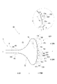
- FIG. 3 is a perspective view for explaining a bundle of sanitary thin paper; It is a top view for demonstrating an outlet formation part. It is a perspective view for demonstrating the usage condition of the package which concerns on this invention. It is a partially enlarged view for explaining an outlet forming portion having a deformed cut portion. It is a partially enlarged view for explaining another outlet forming portion having a deformed cut portion. It is a partially enlarged view for explaining an outlet forming portion having a convex cut portion. It is a partially enlarged view for explaining another form of the convex cut portion.
- FIG. 3 is a perspective view for explaining a bundle of sanitary thin paper; It is a top view for demonstrating an outlet formation part. It is a perspective view for demonstrating the usage condition of the package which concerns on this invention. It is a partially enlarged view for explaining an outlet forming portion having a deformed cut portion. It is a partially enlarged view for explaining another outlet forming portion having a deformed cut portion. It is a partially enlarged view
- FIG. 10 is a perspective view for explaining a usage mode of a package having an outlet forming portion having a convex cut portion; It is a partially enlarged view for explaining an outlet forming portion having a half-cut portion. It is the front view and sectional drawing for demonstrating a half cut part. It is a figure for demonstrating another example of a form of an outlet formation part.
- FIG. 10 is a diagram for explaining tearing at the time of forming the outlet;
- FIGS. 1 to 12 and FIG. 13 showing a comparative embodiment.
- directions such as up-down direction and left-right direction in the present invention and this specification are changed depending on the orientation of the package, and do not mean the absolute direction of the space.
- rigidity is sometimes referred to as stiffness, rigidity, and stiffness of paper.
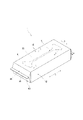
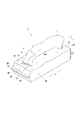
- a packaging body 1 according to the present invention is a bundle 3 of sanitary thin paper sheets 2 such as paper towels folded and stacked, and wrapped in a flexible packaging film 4.
- An outlet forming portion 5 is provided on an upper surface 4C. have.
- the package 1 has a top surface 4C, a bottom surface 4D facing the top surface 4C, and long and short sides 4B and 4A positioned between the top surface 4C and the bottom surface 4D so as to approximate the shape of the bundle 3. It has a substantially hexahedral shape.
- the gusset packaging of this embodiment is pillow packaging with a gusset, in which a bundle 3 as an object to be packaged is wrapped in a cylindrical shape so that openings are formed at both ends in the longitudinal direction with a packaging film 4, and the winding is performed.
- the portion 4X that overlaps in the direction is adhered at the bottom of the bundle 3 by fusion treatment or adhesive, and the edge of the portion extending beyond the short side surface 3A of the bundle 3 is pressed vertically while forming a gusset.
- the short side 4A is used as a sealing surface by bonding with a fusion process or an adhesive.
- the sealing surface which is the short side surface 4A
- the long side surface 4B which is the gusset
- the packaging form of the package 1 is not limited.
- a simple pillow packaging without a gusset may be used, or other appropriate packaging forms such as overlap packaging, also called caramel packaging, formed by overlapping and fused flaps on the short sides may be used.
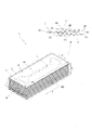
- the bundle 3 of sanitary thin paper 2 contained in the package 1 according to the present invention is a so-called pop-up bundle. As shown particularly in FIG. 2, this bundle 3 is such that the rectangular sanitary thin paper 2 is folded in two, and the folded pieces 2B of the other sanitary thin papers 2 located above and below are positioned on the folded inner side 2A.
- a plurality of sanitary thin paper sheets 2 are folded and laminated, and has a pair of longitudinal side surfaces 3B where the folding edges 2C of each sanitary thin paper sheet 2 are arranged, a pair of short side surfaces 3A where the folding edges 2C are not arranged, and further the short side surfaces. It has a substantially rectangular parallelepiped shape having a pair of flat surfaces (upper and lower surfaces) 3C that are connected to 3A and longitudinal side surfaces 3B.
- the number of sets of sanitary thin paper 2 constituting the bundle 3 is not limited, but can be 30 to 240 sets with one ply or multiple plies as one set.
- the size of the bundle 3 is also not limited, but a bundle of 200 sets of sanitary thin paper is preferably 30 to 100 mm in height x 150 to 250 mm in the longitudinal direction (width) x 100 to 130 mm in the lateral direction (depth). . Further, when the height of the bundle is shorter than the length of the upper surface of the bundle in the depth direction, the pop-up failure improvement effect of the present invention is enhanced.
- the filling rate of the bundle 3 in the package 1 is not limited as long as it does not interfere with the effects of the present invention, but the gap between the bundle and the packaging film is preferably in the range of 0 to 30 mm.
- the bundle 3 may be wrapped in a slightly compressed state in the vertical direction with the wrapping film.
- Each of the sanitary thin papers 2 constituting the bundle 3 has a single-layer structure of one sheet or a laminated structure of a plurality of sheets.
- the number of plies is not limited, it is preferable to use one layer (1 ply) or two layers (2 plies).
- the basis weight per ply is not limited, it is preferably 10 to 40 g/m 2 . Desirably, the mass per set is 1.0 to 2.5 g.
- the sanitary thin paper with one or two plies of sheets having the above basis weight is particularly suitable for paper towels suitable for wiping hands after washing hands. Furthermore, it is desirable that the thickness of one set of this sanitary thin paper is 100 to 500 ⁇ m.
- Sanitary thin paper with such a number of plies, a basis weight, and a paper thickness is the following sanitary paper at the time of pop-up due to the shape of the characteristic outlet forming part having the narrow width part, the wide part, and the curved convex part, which are the configurations of the present invention. It is highly effective in improving pop-up defects in which the thin paper falls without being pulled up, and erection defects in which the package does not stand up and falls down.
- the basis weight is based on the measurement method of JIS P 8124 (1998).
- the thickness of the paper was determined by fully conditioning the test piece under the conditions of JIS P 8111 (1998), and then using a dial thickness gauge (thickness measuring instrument) "PEACOCK G type" (manufactured by Ozaki Seisakusho Co., Ltd.) under the same conditions. and the value measured in the state of multiple plies using an equivalent machine.
- the sanitary thin paper 2 according to the present invention is a dry type, not a so-called wet type impregnated with a chemical solution. Therefore, the bundle 3 formed by the sanitary thin paper 2 contains a lot of air.
- a chemical solution such as a moisturizing component that increases moisture by absorbing moisture such as polyol represented by glycerin is added. good too.
- the raw material pulp constituting the sanitary thin paper 2 is not limited.
- a mixture of softwood-derived pulp such as NBKP and hardwood-derived pulp such as LBKP may be mentioned.
- waste paper pulp may be blended, or waste paper pulp may be used alone.
- the softwood-derived pulp is more than 50% in order to exhibit particularly excellent effects in sanitary thin papers such as paper towels that have strong stiffness and high rigidity.
- dry tensile strength of the sanitary tissue paper 2 is not limited, those having a longitudinal direction of 1000-3000 cN/25 mm and a lateral direction of 250-1500 cN/25 mm are particularly suitable for the present invention. Dry tensile strength is measured according to JIS P8113 (1998). Examples of measuring devices include Minebea Co., Ltd.'s "Universal Tensile Compression Tester TG-200N" and its equivalent.
- the outlet forming portion 5 of the package 1 according to the present invention is formed by arranging an easy tear line 50 in a ring on the upper surface 4C facing the uppermost sanitary thin paper 2 of the bundle 3 of the packaging film 4 .
- an easy tear line 50 in this specification does not mean that the shape is limited to a circular shape or an elliptical shape, but means a shape in which a closed region is formed.
- Such an outlet forming portion 5 tears the easy-cleavage line 50, separates and removes the range surrounded by the easy-cleavage line 50, and draws out the sanitary thin paper 2 to the upper surface 4C of the package 1.
- An outlet 6, which is an opening of the is formed.
- the bundle 3 is of a pop-up type, when one sheet of sanitary thin paper 2 at the top of the bundle 3 is pulled out from the formed outlet, the next sanitary sheet located immediately below it is pulled out. A part of the thin paper comes to be exposed from the outlet.
- the outlet forming portion 5 has the easy-cleavage lines 50 arranged in a ring, the outlet 6 formed by separating and removing the range surrounded by the easy-cleavage lines 50 is formed only in a straight line. It does not have a slit shape, but has a certain width in the depth direction.
- Such outlet-forming portion 5 is formed by tearing off a range surrounded by easy-cleavage line 50 so as to continuously pull from one end portion 5A toward the other end portion 5B. Since the film in the range of can be separated and removed, it is excellent in operability at the time of opening.
- the end located on the left side of the drawing is described as one end 5A, and the end located on the right side is described as the other end 5B. These can be replaced.
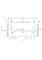
- the outlet forming portion 5 of the package 1 according to the present invention is characterized by the narrow portion 51 extending in the width direction at the central portion in the depth direction of the upper surface 4C and the end portions of the narrow portion 51. and a widened portion 52 that gradually widens outward in the width direction of the bundle 3 as it moves away from the narrow portion 51 and continues to the widened portion 52 and bulges outward in the width direction of the bundle 3 .
- the length L1 in the width direction of the entire outlet forming portion 5 is 70% or more of the length L2 in the width direction of the upper surface of the bundle 3.
- the maximum length L3 in the depth direction of the entire outlet forming portion 5 is 10 to 40% of the length L4 in the depth direction of the upper surface of the bundle 3
- the length L5 in the width direction of the narrow portion is the length of the upper surface of the bundle 3. It is 50 to 70% of the length L2 in the width direction
- the length L6 in the depth direction of the narrow portion is 0.5 to 10% of the length L4 in the depth direction of the upper surface of the bundle 3.
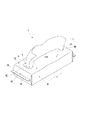
- the outlet 6 formed by the outlet forming portion 5 has a substantially trapezoidal free edge piece 51A in the vicinity of the edge extending from the narrow width portion 51 to the widened portion 52, which is easily movable in the vertical direction.
- the edge piece 51A is deformed so that it can be slightly turned up in the direction of pulling out, and particularly as shown in FIG. In response, they lean back and support it.
- the outlet forming portion 5 within the above range, in particular, because of the shape having the widened portion 52 that continues from the narrow portion 51 that is very narrow in the depth direction to the curved convex portion 53 that is very wide in the depth direction, A free edge piece 51A formed in the vicinity of the edge of the narrow portion 51 is very wide and large in the outlet 6 formed. Therefore, when the sanitary thin paper 2 is pulled out, the space between the narrow parts 51 can be widened, and the sanitary thin paper 2 having a relatively high rigidity can be smoothly taken out from the bundle 3. ⁇ Further, the edge piece 51A firmly leans against the sanitary thin paper 2 having high rigidity, thereby enhancing the effect of preventing the sagging.
- the packaging film at the position is in a packaging form that is easily deformed, or the sanitary thin paper to be enclosed is a highly rigid sanitary thin paper 2 such as a paper towel with the above basis weight and paper thickness, and the upper surface position of the package 1 is deformed when it is pulled out. Even if the sanitary thin paper 2 is easily pulled out, the whole upper surface is easily maintained flat without being distorted when the sanitary thin paper 2 is pulled out, and when the sanitary thin paper 2 is taken out one by one, it is particularly stable and easy to take out.
- the outlet forming portion 5 configured according to the present invention is a curved convex portion 53 that is wide in the depth direction, the length of the edge of the curved convex portion 53 is increased and the width of the outlet forming portion 5 is increased.
- a deep recessed portion 6H is formed between the portion 52 and the curved convex portion 53 when the outlet 6 is formed. Therefore, the root portion 2R of the next sanitary thin paper, which is partially exposed from the outlet 6 following the sanitary thin paper pulled out from the bundle 3, is deformed so as to be gently rolled along the edge 6E of the curved convex portion 53. . Since the sanitary thin paper 2 having a high rigidity is hard to be bent, the uprightness is enhanced by gentle winding.
- the root portion 2R of the next sanitary thin paper partly exposed from the outlet 6 fits into the deep recessed portion 6H, the uprightness is further enhanced.
- the pop-up failure due to the depression of the inside of the packaging film of the sanitary thin paper which is likely to occur when the sanitary thin paper has high rigidity, is less likely to occur due to the above action.
- This action and effect is particularly effective in combination with the sanitary thin paper having the suitable basis weight and paper thickness as well as the suitable packaging film described later.
- the widened portion 52 is arranged so that the easy tearing line 50 gradually increases in angle with respect to the width direction toward the outside in the width direction of the bundle 3 . Moreover, it is desirable that the easy-cleavage line 50 forming the edge of the widened portion 52 has a taper angle ⁇ of 25 to 60 degrees with respect to the width direction.
- the easy-cleavage line 50 is formed in a curved line and connected smoothly.
- the easy-cleavage line 50 is easily cleaved smoothly from the widened portion 52 toward the curved convex portion 53 .
- the length L3 of the curved convex portion 53 in the depth direction is specifically 25 to 45 mm, and the bulging length L7 in the width direction is 2.5 to 12.5 mm.
- the flexible resin-made packaging film 4 constituting the exterior of the package 1 include polyethylene film, polypropylene film, polyester film, polyethylene terephthalate film, nylon film, vinylidene chloride film, and ethylene vinyl alcohol.
- examples include monolayer films of copolymers, appropriately laminated laminate films containing these films, and gas barrier films obtained by subjecting these films to surface treatment such as aluminum vapor deposition.
- Biomass films derived from plant materials such as sugarcane, potato (starch), and corn can also be used. The use of such biomass films is desirable from the viewpoint of environmental protection.
- Polypropylene film and polyethylene film are particularly suitable.
- the packaging film 4 may be a satin-finished film which is excellent in design and touch.
- the melting point of the film is preferably 150° C. or lower. The lower the melting point of the packaging film, the lower the heat-sealing treatment can be performed, but the practical lower limit is 80°C.
- Examples of polypropylene films include unstretched polypropylene films (CPP), and examples of polyethylene films include linear low-density polyethylene films (LLDPE), low-density polyethylene films (LDPE), and medium-density polyethylene films (MDPE).
- ethylene vinyl alcohol copolymer resin film and polyethylene terephthalate resin film which have excellent fragrance retention properties, are desirable for packaging scented tissue paper and other scented items. Even if it is a multi-layer resin film in which a polyethylene resin film or a polypropylene resin film is laminated on one or both sides of an ethylene vinyl alcohol copolymer resin film or a polyethylene terephthalate resin film to enhance the heat-sealing property. good.
- the thickness of the packaging film 4 may be selected as appropriate, but the thickness measured according to JIS P 8118 (1998) is preferably 25 to 75 ⁇ m. If the thickness is 25 to 75 ⁇ m, the effects of the present invention can be exhibited particularly effectively.
- dial thickness gauge thickness measuring instrument
- PACOCK G-1A type manufactured by Ozaki Seisakusho Co., Ltd.
- the softness of the packaging film 4 is smaller than the softness of the sanitary thin paper 2.
- the softness of the packaging film 4 is smaller than the softness of the sanitary thin paper 2, the effects of the present invention can be exhibited particularly effectively.
- the easy tear line 50 constituting the outlet forming portion 5 according to the present invention can be a perforation, a slit cut provided with an uncut portion (non-cut portion), or the like. However, it is not limited to this.
- the type of perforations is not limited as long as the cut portions 50C and the non-cut portions 50U are alternately arranged. Examples include normal perforations in which the cut portion 50C is a straight line, micro perforations in which the cut portion is a hole, and zipper perforations in which the shape of the cut portion is Y-shaped, substantially L-shaped, or ⁇ -shaped.
- a slit cut is a portion obtained by cutting a film into a slit shape, and by having a non-cut portion, the non-cut portion and the cut portion are arranged alternately.
- a slit cut having a non-cut portion may be simply referred to as a slit cut.
- Slit cuts with perforations and non-cut parts may not be distinguished, but in the present invention, slit cuts are defined as slits when the cut part is less than 2 pitches, that is, when the cut part of the same length does not continue twice It's called cut. In general, the slit cut is formed so that the length of the cut portion is longer than the perforations.
- the cut tie ratio of the slit cut with perforations and non-cut parts is determined at an appropriate interval depending on the ease of breaking of the film used, but the length of the cut part is 0.8 mm or more and 20.0 mm or less, non-cut
- the length of the cut portion (tie portion or uncut portion) is preferably designed appropriately within the range of 0.3 mm or more and 5.0 mm or less.
- the longitudinal direction X is formed as shown in FIG. 13(b). While there is an advantage that an outlet can be easily formed by tearing off the annular perforated area 105Z from the one end 105A toward the other end 105B, the other end 105B is finally opened by such an opening operation. 13 ( As shown in c), the tearing of the perforations 150 does not occur smoothly and continuously at this end, particularly in the vicinity of the perforations 150e at the end of the other end 105B. It is conceivable that an unintentional tear 105P occurs at the end of outlet 106 . As the width direction end of the outlet forming portion 105 is expanded in the depth direction Y, the perforation range that is closer to the direction perpendicular to the tear-off direction becomes longer, and this tear occurs. It is thought that it will become easier.
- the portion 50P includes a deformed cut portion 50D having an end cut portion 50e and a portion cut into a doglegged shape at one end or both ends, and a non-cut portion.
- 50U can be a characteristic perforation 50P 1 alternately arranged.
- 80% or more, preferably 90% or more, particularly preferably 95% or more of the portion constituting the edge of the curved convex portion 53 is alternately arranged with the deformed cut portion 50D and the uncut portion 50U.
- a portion 50P is desirable.
- the entire range of the curved convex portion 53 may be composed of easy-cleavage lines in which deformed cut portions 50D and non-cut portions 50U are alternately arranged.
- the modified cut portion 50D is formed at one end or both ends of the main cut portion 50m on a straight or substantially straight gently curved line at a predetermined angle.
- the end cut portion 50e is continuously arranged, and one end or both end portions have a V-shaped cut portion.
- the deformed cut portion 50D includes a deformed cut portion 50D1 formed in a doglegged shape at one end and a deformed cut portion 50D2 formed in a doglegged shape at both ends. There may be. As shown in FIG.
- the end of one end cut portion 50e faces the outer side of the upper surface of the bundle 3 in the width direction, and the end of the other end cut portion 50e faces the central side of the upper surface of the bundle 3 in the width direction.
- the ends of 50e may be arranged only toward the outer side in the width direction of the upper surface of the bundle 3, or, as in the form shown in FIG. Only the ones to which they are directed may be arranged. Furthermore, the ends of the end cut portions 50e may be directed outward in the width direction of the upper surface of the bundle 3 and may be directed toward the central side in the width direction of the upper surface of the bundle 3 together. Furthermore, as shown in FIG.
- the deformed cut portion 50D at the end (the other end 5B in the illustrated example) is cut. and the non - cut portion 50U are alternately arranged, if both the adjacent end cut portions 50e of the adjacent deformed cut portions 50D are directed outward in the width direction of the upper surface of the bundle 3, or , the extending direction of the adjacent end cut portions 50e intersects with each other in the direction toward the width direction center side of the upper surface of the bundle 3, so that the non-cut portion 50U between them Easy to cut.
- the position of the end of the deformed cut portion 50D is the main cut by the end cut portion 50e. Since the position is slightly shifted inward or outward in the width direction from the extending direction of the portion 50m, when the outlet 6 is formed, the portion that was the uncut portion 50U becomes slightly convex and has a serrated edge. For this reason, when drawing out a set of sanitary thin papers 2 from the bundle 3, the serrations are applied to the base portion 2R of the next set of sanitary thin papers 2, which is partially exposed from the take-out port following the taken out sanitary thin papers. The edge of the shape clamps the edge in the width direction of the sanitary thin paper 2 to enhance the prevention of falling.
- the deformed cut portion 50D is positioned on the width direction extension line of the center C in the depth direction of the narrow portion 51, and the deformed cut portion is provided at both ends in the width direction.
- a modified cut portion 50D2 having an end cut portion 50e directed outward, and a modified cut portion positioned further outward in the depth direction than the modified cut portion 50D2 extends from the center C of the narrow portion 51 in the depth direction.
- a deformed cut portion 50D 1 having an end cut portion facing outward in the width direction is provided only at the end portion located outward in the depth direction.
- the deformed cut portion 50D is deformed.
- the edge cut portions 50e of the adjacent modified cut portions 50D 1 and 50D 2 are present at positions on the outer side in the width direction preceding the edge having no edge cut portion 1 in the tensile direction. Therefore, when the non-cut portion 50U therebetween is torn during the opening operation, even if a minute tear occurs in the packaging film, the tear easily continues to the already torn end cut portion 50e immediately after that. , it becomes difficult to tear further.
- the length ratio to the uncut portion 50U is not necessarily limited, but the length L8 of the modified cut portion 50D is not limited, but is 5 mm or more and 20 mm. Below, preferably 7 mm or more and 13 mm or less is desirable. Moreover, it is desirable that the length L9 of the end cut portion 50e of the modified cut portion 50D is 0.2 mm or more and 3.0 mm or less, preferably 0.5 mm or more and 2.5 mm or less. Furthermore, it is desirable that the length L11 of the uncut portion 50U between the deformed cut portions 50D is 0.2 mm or more and 3.0 mm or less, preferably 0.3 mm or more and 2.0 mm or less. Within this range, tearing is extremely difficult to occur between the deformed cut portions 50D, and the non-cut portions 50U are cut, so that the tearing progresses smoothly and continuously.
- the angle ⁇ between the main cut portion 50m and the end cut portion 50e in the doglegged portion of the modified cut portion 50D should be 90° or more. It is preferably 100° or more, more preferably 120° or more.
- the edge portion 50P includes a convex cut portion 50T tapered outward in the width direction and a base end portion of the convex cut portion 50T. can be a portion 50P 2 configured by alternately disposing the non-cut portions 50U that connect the .
- the portion constituting the edge of the curved convex portion 53 is a portion where the convex cut portion 50T and the non-cut portion 50U are alternately arranged. It is good that it is 50P 2 .
- the entire range of the curved convex portion 53 may be composed of easy-cleavage lines in which convex cut portions 50T and non-cut portions 50U are alternately arranged.
- the convex cut portion may have a shape in which a plurality of convex shapes are connected and continuous at the base end portion. Although the number of continuous convex shapes is not necessarily limited, it is desirable to be about 2 to 5.
- a convex cut portion having only one convex shape and a convex cut portion having a continuous convex shape may be mixed. .
- the shape of the convex cut portion 50T may be any shape as long as the outer side in the width direction is tapered. It can also be a trapezoidal shape as shown in FIG. 8(b). Further, the widthwise outer side is tapered means that the tip portion of the convex cut portion 50T is not directed toward the depth direction Y and the widthwise center side.
- the angle ⁇ with respect to the depth direction Y of the tip of the convex cut portion 50T is 15° or more, preferably 30° or more, and more preferably 45° or more.
- the opening angle ⁇ of the tip portion of the convex cut portion 50T is not necessarily limited as long as it is less than 180°, but is preferably 15 to 120°, more preferably 20 to 90°, and even more preferably 30 to 60°. is.
- the edge of the other end 5B having the convex cut portion 50T , the cut convex portion 50T that has already been cut exists at a position on the outer side in the width direction that precedes the uncut portion 50U between the base ends of the cut convex portions 50T in the pulling direction.
- the non-cut portion 50U between the base ends of the convex cut portions 50T is torn during the opening operation, even if a minute tear occurs in the packaging film, the tear has already occurred immediately after that. The tear does not progress any further continuously from the cut portion 50T.
- the convex cut portion 50T and the non-cut portion 50U connecting the base ends of the convex cut portion are alternately arranged.
- Forming 50P significantly reduces the risk of cracking.
- a portion 50P configured by alternately arranging convex cut portions 50T tapering outward in the width direction and non-cut portions 50U connecting the base end portions of the convex cut portions 50T. 2 becomes a jagged serrated edge on which a plurality of projections 6T are arranged when the outlet 6 is formed.
- these convex pieces 6T can be turned over in the direction in which the sanitary thin papers are pulled out. It does not prevent deformation into a highly upright shape by being caught along. In addition, the sanitary thin paper can be pulled out smoothly.
- the height L12 from the base end side to the tip end of the convex cut portion 50T is 0.1 mm or more.
- the upper limit is not necessarily limited, it is desirable to set it in a range not exceeding 10 mm.
- a preferred height of the convex cut is 0.5 to 7 mm, more preferably 1 to 5 mm.
- a convex cut portion having a height of less than 1.0 mm is called a microwave cut and can be formed by a technique.
- Such a low-height convex cut portion 50T is formed by a portion in which the convex cut portion 50T and the non-cut portion 50U connecting the base end portion of the convex cut portion are alternately arranged.
- the unevenness of the saw-toothed edge of the outlet 6 has an inconspicuous design.
- the ratio of the length L13 between the base ends of both ends of the convex cut portion 50T and the length L14 of the non-cut portion 50U between the base ends of the adjacent convex cut portions 50T is not necessarily limited,
- the length L13 between the proximal ends is 5 mm or more and 20 mm or less, preferably 7 mm or more and 13 mm or less, and the length L14 of the uncut portion 50U is 0.3 mm or more and 3 mm or less, preferably 0.7 mm or more. 0.3 mm or less is preferable. Within this range, unintended tearing does not occur, and smooth and continuous tearing tends to proceed.
- the edge portion 50P can be a portion 50P3 composed of alternate cut portions 50C and half-cut portions 50H.
- 80% or more, preferably 90% or more, particularly preferably 95% or more of the portion constituting the edge of the curved convex portion 53 is the portion 50P where the cut portions 50C and the half-cut portions 50H are alternately arranged. 3 is good.
- the entire range of the curved convex portion 53 may be composed of an easy-cleavage line in which cut portions 50C and half-cut portions 50H are alternately arranged.
- the cut portion 50C and the half-cut portion 50H are shown in plan view in FIG.
- the half-cut portion 50H is completely cut from the front side 41, which is the side not facing the bundle 3, to the back side 42, which is the side facing the bundle 3. It is a portion cut to a predetermined depth range L15 in the thickness direction Z from the surface side 41 to the back surface side 42 .
- the portion where the cut portions 50C and the half-cut portions 50H are alternately arranged has a more easily tearable line than the portion where the cut portions 50C and the uncut portions 50U with no cuts are alternately arranged.
- the cleaving tends to progress continuously and smoothly.
- the difference between the cut portion 50C and the half-cut portion 50H is smaller than the difference between the cut portion 50C and the non-cut portion 50U. This is because tearing progresses continuously and smoothly from 50C to the half-cut portion 50H and from the half-cut portion 50H to the cut portion 50C. Therefore, even if the unsealing operation is performed by continuously pulling the outlet forming portion 5 from the one end portion 5A toward the other end portion 5B, the packaging film 4 is unintentionally removed at the other end portion 5B which is cut off last. less likely to tear.
- the half-cut portion 50H is cut to a depth of 20% or more of the thickness L16 of the packaging film. If the cut is 20% or more, a continuous and smooth tear can be sufficiently generated between the cut portion 50C and the half-cut portion 50H when forming the outlet by the opening operation.
- the upper limit of the depth of cut is not limited, but if it is 80% or less, more preferably 60% or less, unintended tearing is less likely to occur.
- the length ratio between the cut portion 50C and the half-cut portion 50H at the end of the outlet forming portion 5 is not necessarily limited, but the length of the cut portion 50C is 5 mm or more and 20 mm or less, preferably 7 mm or more and 13 mm.
- the length of the half-cut portion 50H should be in the range of 0.3 mm or more and 3 mm or less, preferably 0.7 mm or more and 1.3 mm or less. Within this range, tearing progresses smoothly from the cut portion 50C to the half-cut portion 50H and from the half-cut portion 50H to the cut portion 50C, and unintended tearing hardly occurs.
- half-cut portions are provided between the deformed cut portions 50D, between the convex cut portions, and between the cut portions at the perforations other than the end portions.
- portions 50P 1 where the deformed cut portions 50D and the uncut portions 50U are alternately arranged are located at both ends of the outlet forming portion 5. may be present, or may be present only at one end.
- the portions 50P 2 in which the convex cut portions 50T and the non-cut portions 50U are alternately arranged may also be located at both ends of the outlet forming portion 5, or may be located at only one end.
- the portions 50P3, which are formed by alternately arranging the cut portions 50C and the half-cut portions 50H may be located at both ends of the outlet forming portion 5, or may be located at only one end.
- end portions 50P 1 , 50P 2 and 50P 3 are formed only at one end portion, the opposite end portion, for example, as shown in FIG.
- the range L10 from the middle of the widened portion 52A on one side to the position exceeding the outer side end 53t of the curved convex portion 53A can be a continuous cut portion.
- a free piece 5T is formed in a range from one depth side to the outer side end at one end 5A of the outlet forming portion 5, and the free piece 5T is formed. It becomes easier to pick up and roll up, and the opening operation becomes easier.
- the edge portion of the narrow portion 51 according to the present invention is uncut rather than a half-cut portion because the direction of pulling during the opening operation from the one end portion 5A to the other end portion 5B coincides with the extending direction. It is desirable to configure it with perforations having a part. This is desirable because it makes it difficult for the edge of the narrow portion 51 to unintentionally tear.
- the easy-cleavage line 50 is a slit cut having perforations and a non-cut portion, including a portion where the cut portion 50C and the half-cut portion 50H are alternately arranged, for example, formed at once by die cutting. can do.
- Examples 1 to 5 of the present invention and Comparative Example 1 were produced, and tests were conducted on the sinking of the sanitary thin paper and the tearing of the unsealing outlet.
- the shape of the outlet forming portion of the package according to Examples 1 to 5 is a substantially gourd shape having a narrow portion, a wide portion, and a curved convex portion as shown in FIGS.
- the outlet forming portion of the package according to Comparative Example 1 is a simple linear perforation.
- a bundle of 1-ply paper towels (trade name: Raku La Cook Kitchen Paper, basis weight: 20 g/m 2 , paper thickness: 220 ⁇ m) was folded up in a pop-up manner.
- the packaging form according to each example is gusset packaging, and the stretching direction of the packaging film is a direction orthogonal to the width direction of the outlet forming portion.
- the easy tearing line related to the outlet forming part is cleaved to form an outlet, and the paper towels constituting the bundle are pulled out from the outlet in order up to the last one. , counted the number of times the drop actually occurred.
- Table 1 shows the dimensions of the outlet forming part, the ratio of the length in the depth direction and the length in the width direction of the upper surface of the bundle, and the test results in each example.
- Comparative Example 1 in which the ejection opening forming portion was a single perforation and the ejection opening was a slit, had 12 depressions.
- the number of drops was 0 and no drop could be confirmed.
- the ejection port having the shape of the ejection port forming portion having the narrow portion, the widened portion, and the curved convex portion is particularly excellent in preventing sagging.
- the maximum length of the outlet in the depth direction that is, The length in the depth direction of the curved convex portion, which is the end portion, is as long as 35 mm, and the range is as much as 30% of the depth direction of the upper surface of the bundle.
- Example 5 the portion between the cut portions of the curved convex portion in Example 1 is not a half-cut portion, but a conventional general non-cut portion. Some of them were found to have cracks at the ends. In the case of an easy-cleavage line that constitutes the edge of a very long curved convex portion as in Examples 1 to 4, it is possible to alternately arrange a cut portion and a half-cut portion for that portion. , it was also confirmed that the opening operability is enhanced.
- the package according to the present invention is a film package that is excellent in drawing out sanitary thin paper, especially hard sanitary thin paper such as paper towels.
- Narrow width portion 51A Approximately trapezoidal edge piece 52: Widened portion 53: Curved convex portion ⁇ : Taper angle of widened portion ⁇ : Open angle of V-shaped portion ⁇ : With respect to the depth direction Angle of direction of convex cut part, ⁇ : Tip angle of convex cut part.
- L1 length in the width direction (longitudinal direction) of the outlet forming portion
- L2 length in the width direction (longitudinal direction) of the upper surface of the bundle
- L3 maximum length in the depth direction (lateral direction) of the outlet forming portion
- L4 length of the upper surface of the bundle in the depth direction (transverse direction)
- L5 length of the narrow portion in the width direction (longitudinal direction)
- L6 length of the narrow portion in the depth direction (transverse direction)
- L7 length in the width direction (longitudinal direction) of the outlet forming portion
Abstract
Description
その第一の手段は、
衛生薄葉紙の束が柔軟な樹脂製の包装フィルムによって包装されているフィルム包装ティシューであり、
上面に易裂開線を環状に配して形成された取出口形成部を有し、
取出口形成部は、
奥行方向中央部において幅方向に延在する幅狭部と、この幅狭部の端部に連続して幅方向外方に向かって幅狭部より離れるにつれて漸次広くなる拡幅部と、この拡幅部に連続して幅方向外方に向かって凸に膨出する湾曲凸部と、を有する形状をなし、
その幅方向の長さが上面の幅方向の長さの70%以上であり、奥行方向の最大長さが上面の奥行方向の長さの10~40%であり、前記幅狭部の幅方向の長さが上面の幅方向の長さの50~70%であり、前記幅狭部の奥行方向の長さが上面の奥行方向の長さの0.5~10%である、
ことを特徴とするフィルム包装ティシューである。 Means for solving the above problems are as follows.
The first means is
A film-wrapped tissue in which a bundle of sanitary thin paper is wrapped in a flexible resin-made wrapping film,
Having an outlet forming portion formed by arranging an easy-cleavage line in a ring on the upper surface,
The outlet forming part is
A narrow portion extending in the width direction at the central portion in the depth direction, a widened portion continuously extending from the end of the narrow portion and gradually widening outward in the width direction as the distance from the narrow portion increases, and the widened portion. and a curved convex portion that continuously bulges outward in the width direction,
The length in the width direction is 70% or more of the length in the width direction of the upper surface, the maximum length in the depth direction is 10 to 40% of the length in the depth direction of the upper surface, and the width direction of the narrow portion The length in the width direction of the upper surface is 50 to 70%, and the length in the depth direction of the narrow portion is 0.5 to 10% of the length in the depth direction of the upper surface.
A film-wrapped tissue characterized by:
湾曲凸部の奥行方向の長さが25~45mm、幅方向の膨出長が2.5~12.5mmである、上記第一の手段に係るフィルム包装ティシューである。 The second means is
The film-wrapped tissue according to the first means, wherein the length of the curved convex portion in the depth direction is 25 to 45 mm, and the bulging length in the width direction is 2.5 to 12.5 mm.

41…包装フィルムの表面側、42…包装フィルムの裏面側、50…易裂開線、50D,50D1,50D2,50D3…変形カット部、50m…主カット部、50e…端カット部、R…く字型部分の曲率、50C…カット部、50U…非カット部(タイ部)、50T…凸カット部、50P…取出口形成部の端部の縁、50P1…変形カット部と非カット部が交互に配されている部分、50P2…凸カット部と非カット部が交互に配されている部分、50P3…カット部とハーフカット部が交互に配されている部分、51…幅狭部、51A…略台形状の縁片、52…拡幅部、53…湾曲凸部、∠α…拡幅部のテーパー角、∠β…く字型部分の開き角度、∠γ…奥行方向に対する凸カット部の向きの角度、∠Δ…凸カット部の先端部角度。
L1…取出口形成部の幅方向(長手方向)長さ、L2…束上面の幅方向(長手方向)の長さ、L3…取出口形成部の奥行方向(短手方向)の最大長さ、L4…束上面の奥行方向(短手方向)の長さ、L5…幅狭部の幅方向(長手方向)の長さ、L6…幅狭部の奥行方向(短手方向)の長さ、L7…湾曲凸部の幅方向の膨出長、
L8…変形カット部の長さ、L9…端カット部の長さ、L10…奥行き方向の一方側の拡幅部の途中から湾曲凸部の外方側端を超える位置までの範囲、L11…変形カット部間の非カット部の長さ。
L12…凸カット部の高さ、L13…凸カット部の基端間の長さ、L14…凸カット部間の非カット部の長さ。
L15…ハーフカット部の深さ、L16…包装フィルムの厚み、
105…取出口形成部、105A…取出口形成部の一方端部、105B…取出口形成部の他方端部、105P…フィルムの裂け、150…ミシン目、150e…幅方向端のミシン目、X…長手方向(幅方向)、Y…長手方向に直交する方向(奥行方向)、Z…包装フィルムの厚み方向、C…幅狭部の奥行方向の中央。 1
41 Front side of
L1: length in the width direction (longitudinal direction) of the outlet forming portion, L2: length in the width direction (longitudinal direction) of the upper surface of the bundle, L3: maximum length in the depth direction (lateral direction) of the outlet forming portion, L4: length of the upper surface of the bundle in the depth direction (transverse direction), L5: length of the narrow portion in the width direction (longitudinal direction), L6: length of the narrow portion in the depth direction (transverse direction), L7. … the length of protrusion in the width direction of the curved protrusion,
L8: Length of modified cut portion, L9: Length of end cut portion, L10: Range from the middle of the widened portion on one side in the depth direction to the position beyond the outer end of the curved convex portion, L11: Modified cut Length of uncut part between parts.
L12...height of the convex cut portion, L13...length between base ends of the convex cut portion, L14...length of the non-cut portion between the convex cut portions.
L15: depth of half-cut portion, L16: thickness of packaging film,
105... Outlet forming part, 105A... One end of the outlet forming part, 105B... The other end of the outlet forming part, 105P... Film tear, 150... Perforation, 150e... Perforation at the end in the width direction, X : longitudinal direction (width direction), Y: direction perpendicular to the longitudinal direction (depth direction), Z: thickness direction of the packaging film, C: center of the narrow portion in the depth direction.
Claims (2)
- 衛生薄葉紙の束が柔軟な樹脂製の包装フィルムによって包装されている包装体であり、
上面に易裂開線を環状に配して形成された取出口形成部を有し、
取出口形成部は、
奥行方向中央部において幅方向に延在する幅狭部と、この幅狭部の端部に連続して幅方向外方に向かって幅狭部より離れるにつれて漸次広くなる拡幅部と、この拡幅部に連続して幅方向外方に向かって凸に膨出する湾曲凸部と、を有する形状をなし、
その幅方向の長さが上面の幅の70%以上であり、奥行方向の最大長さが上面の奥行方向の長さの10~40%であり、前記幅狭部の幅方向の長さが上面の長さの50~70%であり、前記幅狭部の奥行方向の長さが上面の奥行方向の長さの0.5~10%である、
ことを特徴とする包装体。 A packaging body in which a bundle of sanitary thin paper is wrapped with a flexible resin packaging film,
Having an outlet forming portion formed by arranging an easy-cleavage line in a ring on the upper surface,
The outlet forming part is
A narrow portion extending in the width direction at the central portion in the depth direction, a widened portion continuously extending from the end of the narrow portion and gradually widening outward in the width direction as the distance from the narrow portion increases, and the widened portion. and a curved convex portion that continuously bulges outward in the width direction,
The length in the width direction is 70% or more of the width of the top surface, the maximum length in the depth direction is 10 to 40% of the length in the depth direction of the top surface, and the length in the width direction of the narrow portion is 50 to 70% of the length of the upper surface, and the length of the narrow portion in the depth direction is 0.5 to 10% of the length of the upper surface in the depth direction.
A package characterized by: - 湾曲凸部の奥行方向の長さが25~45mm、幅方向の膨出長が2.5~12.5mmである、請求項1記載の包装体。 The package according to claim 1, wherein the length of the curved convex portion in the depth direction is 25 to 45 mm, and the bulging length in the width direction is 2.5 to 12.5 mm.
Priority Applications (3)
| Application Number | Priority Date | Filing Date | Title |
|---|---|---|---|
| CN202280009137.6A CN116801775A (en) | 2021-03-31 | 2022-03-16 | Packaging body |
| US18/552,185 US20240057825A1 (en) | 2021-03-31 | 2022-03-16 | Packaged product |
| EP22780131.3A EP4286295A1 (en) | 2021-03-31 | 2022-03-16 | Wrapped body |
Applications Claiming Priority (2)
| Application Number | Priority Date | Filing Date | Title |
|---|---|---|---|
| JP2021-060758 | 2021-03-31 | ||
| JP2021060758A JP2022156860A (en) | 2021-03-31 | 2021-03-31 | package |
Publications (1)
| Publication Number | Publication Date |
|---|---|
| WO2022209911A1 true WO2022209911A1 (en) | 2022-10-06 |
Family
ID=83459046
Family Applications (1)
| Application Number | Title | Priority Date | Filing Date |
|---|---|---|---|
| PCT/JP2022/012000 WO2022209911A1 (en) | 2021-03-31 | 2022-03-16 | Wrapped body |
Country Status (6)
| Country | Link |
|---|---|
| US (1) | US20240057825A1 (en) |
| EP (1) | EP4286295A1 (en) |
| JP (1) | JP2022156860A (en) |
| CN (1) | CN116801775A (en) |
| TW (1) | TW202239670A (en) |
| WO (1) | WO2022209911A1 (en) |
Citations (6)
| Publication number | Priority date | Publication date | Assignee | Title |
|---|---|---|---|---|
| JP2016124598A (en) * | 2015-01-06 | 2016-07-11 | 日本製紙クレシア株式会社 | Paper product-containing carton |
| JP2018052559A (en) | 2016-09-29 | 2018-04-05 | 大王製紙株式会社 | Tissue paper packaging product |
| JP2018058654A (en) | 2017-11-06 | 2018-04-12 | 大王製紙株式会社 | Manufacturing method for film-packaged tissue paper sheets and manufacturing method for assembly-package of film-packaged tissue paper sheets |
| JP2020001796A (en) * | 2018-06-29 | 2020-01-09 | 大王製紙株式会社 | Sanitary tissue paper package |
| WO2020110835A1 (en) * | 2018-11-29 | 2020-06-04 | 大王製紙株式会社 | Sheet packaging body |
| WO2020262236A1 (en) * | 2019-06-28 | 2020-12-30 | 大王製紙株式会社 | Film-packed tissue set package |
-
2021
- 2021-03-31 JP JP2021060758A patent/JP2022156860A/en active Pending
-
2022
- 2022-03-16 CN CN202280009137.6A patent/CN116801775A/en active Pending
- 2022-03-16 EP EP22780131.3A patent/EP4286295A1/en active Pending
- 2022-03-16 US US18/552,185 patent/US20240057825A1/en active Pending
- 2022-03-16 WO PCT/JP2022/012000 patent/WO2022209911A1/en active Application Filing
- 2022-03-28 TW TW111111626A patent/TW202239670A/en unknown
Patent Citations (6)
| Publication number | Priority date | Publication date | Assignee | Title |
|---|---|---|---|---|
| JP2016124598A (en) * | 2015-01-06 | 2016-07-11 | 日本製紙クレシア株式会社 | Paper product-containing carton |
| JP2018052559A (en) | 2016-09-29 | 2018-04-05 | 大王製紙株式会社 | Tissue paper packaging product |
| JP2018058654A (en) | 2017-11-06 | 2018-04-12 | 大王製紙株式会社 | Manufacturing method for film-packaged tissue paper sheets and manufacturing method for assembly-package of film-packaged tissue paper sheets |
| JP2020001796A (en) * | 2018-06-29 | 2020-01-09 | 大王製紙株式会社 | Sanitary tissue paper package |
| WO2020110835A1 (en) * | 2018-11-29 | 2020-06-04 | 大王製紙株式会社 | Sheet packaging body |
| WO2020262236A1 (en) * | 2019-06-28 | 2020-12-30 | 大王製紙株式会社 | Film-packed tissue set package |
Also Published As
| Publication number | Publication date |
|---|---|
| TW202239670A (en) | 2022-10-16 |
| US20240057825A1 (en) | 2024-02-22 |
| EP4286295A1 (en) | 2023-12-06 |
| CN116801775A (en) | 2023-09-22 |
| JP2022156860A (en) | 2022-10-14 |
Similar Documents
| Publication | Publication Date | Title |
|---|---|---|
| JP7224121B2 (en) | Sanitary thin paper package | |
| JP7195511B2 (en) | Perforated film package for opening | |
| JP6771000B2 (en) | Sanitary tissue paper packaging | |
| WO2022209911A1 (en) | Wrapped body | |
| JP7317775B2 (en) | film wrapped tissue | |
| WO2022264578A1 (en) | Packaging body | |
| WO2022209909A1 (en) | Packaging body | |
| CN114401905B (en) | Film package tissue collection package and method for manufacturing film package tissue collection package | |
| WO2022209718A1 (en) | Wrapped body | |
| JP2022154668A (en) | package | |
| JP2022156860A5 (en) | ||
| JP2022190792A5 (en) | ||
| JP2022156859A5 (en) | ||
| JP2022154667A5 (en) | ||
| CN114391000B (en) | Film packaging paper extraction collection package body | |
| JP2022154668A5 (en) | ||
| JP7423885B2 (en) | roll product packaging | |
| KR20200128515A (en) | Sheet package | |
| JP2022115593A (en) | Sanitary tissue paper-containing storage box | |
| JP2023122844A (en) | Storage box with sanitary tissue paper |
Legal Events
| Date | Code | Title | Description |
|---|---|---|---|
| 121 | Ep: the epo has been informed by wipo that ep was designated in this application |
Ref document number: 22780131 Country of ref document: EP Kind code of ref document: A1 |
|
| WWE | Wipo information: entry into national phase |
Ref document number: 202280009137.6 Country of ref document: CN |
|
| WWE | Wipo information: entry into national phase |
Ref document number: 2022780131 Country of ref document: EP |
|
| ENP | Entry into the national phase |
Ref document number: 2022780131 Country of ref document: EP Effective date: 20230830 |
|
| WWE | Wipo information: entry into national phase |
Ref document number: 18552185 Country of ref document: US |
|
| NENP | Non-entry into the national phase |
Ref country code: DE |