WO2022264542A1 - 変倍光学系、光学機器、および変倍光学系の製造方法 - Google Patents
変倍光学系、光学機器、および変倍光学系の製造方法 Download PDFInfo
- Publication number
- WO2022264542A1 WO2022264542A1 PCT/JP2022/009426 JP2022009426W WO2022264542A1 WO 2022264542 A1 WO2022264542 A1 WO 2022264542A1 JP 2022009426 W JP2022009426 W JP 2022009426W WO 2022264542 A1 WO2022264542 A1 WO 2022264542A1
- Authority
- WO
- WIPO (PCT)
- Prior art keywords
- lens group
- optical system
- group
- lens
- variable
- Prior art date
- Legal status (The legal status is an assumption and is not a legal conclusion. Google has not performed a legal analysis and makes no representation as to the accuracy of the status listed.)
- Ceased
Links
Images


Classifications
-
- G—PHYSICS
- G02—OPTICS
- G02B—OPTICAL ELEMENTS, SYSTEMS OR APPARATUS
- G02B15/00—Optical objectives with means for varying the magnification
- G02B15/14—Optical objectives with means for varying the magnification by axial movement of one or more lenses or groups of lenses relative to the image plane for continuously varying the equivalent focal length of the objective
- G02B15/145—Optical objectives with means for varying the magnification by axial movement of one or more lenses or groups of lenses relative to the image plane for continuously varying the equivalent focal length of the objective having five groups only
- G02B15/1451—Optical objectives with means for varying the magnification by axial movement of one or more lenses or groups of lenses relative to the image plane for continuously varying the equivalent focal length of the objective having five groups only the first group being positive
- G02B15/145105—Optical objectives with means for varying the magnification by axial movement of one or more lenses or groups of lenses relative to the image plane for continuously varying the equivalent focal length of the objective having five groups only the first group being positive arranged +-+--
-
- G—PHYSICS
- G02—OPTICS
- G02B—OPTICAL ELEMENTS, SYSTEMS OR APPARATUS
- G02B15/00—Optical objectives with means for varying the magnification
- G02B15/14—Optical objectives with means for varying the magnification by axial movement of one or more lenses or groups of lenses relative to the image plane for continuously varying the equivalent focal length of the objective
- G02B15/145—Optical objectives with means for varying the magnification by axial movement of one or more lenses or groups of lenses relative to the image plane for continuously varying the equivalent focal length of the objective having five groups only
- G02B15/1451—Optical objectives with means for varying the magnification by axial movement of one or more lenses or groups of lenses relative to the image plane for continuously varying the equivalent focal length of the objective having five groups only the first group being positive
- G02B15/145113—Optical objectives with means for varying the magnification by axial movement of one or more lenses or groups of lenses relative to the image plane for continuously varying the equivalent focal length of the objective having five groups only the first group being positive arranged +-++-
-
- G—PHYSICS
- G02—OPTICS
- G02B—OPTICAL ELEMENTS, SYSTEMS OR APPARATUS
- G02B15/00—Optical objectives with means for varying the magnification
- G02B15/14—Optical objectives with means for varying the magnification by axial movement of one or more lenses or groups of lenses relative to the image plane for continuously varying the equivalent focal length of the objective
- G02B15/145—Optical objectives with means for varying the magnification by axial movement of one or more lenses or groups of lenses relative to the image plane for continuously varying the equivalent focal length of the objective having five groups only
- G02B15/1451—Optical objectives with means for varying the magnification by axial movement of one or more lenses or groups of lenses relative to the image plane for continuously varying the equivalent focal length of the objective having five groups only the first group being positive
- G02B15/145121—Optical objectives with means for varying the magnification by axial movement of one or more lenses or groups of lenses relative to the image plane for continuously varying the equivalent focal length of the objective having five groups only the first group being positive arranged +-+-+
-
- G—PHYSICS
- G02—OPTICS
- G02B—OPTICAL ELEMENTS, SYSTEMS OR APPARATUS
- G02B15/00—Optical objectives with means for varying the magnification
- G02B15/14—Optical objectives with means for varying the magnification by axial movement of one or more lenses or groups of lenses relative to the image plane for continuously varying the equivalent focal length of the objective
- G02B15/146—Optical objectives with means for varying the magnification by axial movement of one or more lenses or groups of lenses relative to the image plane for continuously varying the equivalent focal length of the objective having more than five groups
- G02B15/1461—Optical objectives with means for varying the magnification by axial movement of one or more lenses or groups of lenses relative to the image plane for continuously varying the equivalent focal length of the objective having more than five groups the first group being positive
-
- G—PHYSICS
- G02—OPTICS
- G02B—OPTICAL ELEMENTS, SYSTEMS OR APPARATUS
- G02B15/00—Optical objectives with means for varying the magnification
- G02B15/14—Optical objectives with means for varying the magnification by axial movement of one or more lenses or groups of lenses relative to the image plane for continuously varying the equivalent focal length of the objective
- G02B15/16—Optical objectives with means for varying the magnification by axial movement of one or more lenses or groups of lenses relative to the image plane for continuously varying the equivalent focal length of the objective with interdependent non-linearly related movements between one lens or lens group, and another lens or lens group
- G02B15/163—Optical objectives with means for varying the magnification by axial movement of one or more lenses or groups of lenses relative to the image plane for continuously varying the equivalent focal length of the objective with interdependent non-linearly related movements between one lens or lens group, and another lens or lens group having a first movable lens or lens group and a second movable lens or lens group, both in front of a fixed lens or lens group
- G02B15/167—Optical objectives with means for varying the magnification by axial movement of one or more lenses or groups of lenses relative to the image plane for continuously varying the equivalent focal length of the objective with interdependent non-linearly related movements between one lens or lens group, and another lens or lens group having a first movable lens or lens group and a second movable lens or lens group, both in front of a fixed lens or lens group having an additional fixed front lens or group of lenses
- G02B15/173—Optical objectives with means for varying the magnification by axial movement of one or more lenses or groups of lenses relative to the image plane for continuously varying the equivalent focal length of the objective with interdependent non-linearly related movements between one lens or lens group, and another lens or lens group having a first movable lens or lens group and a second movable lens or lens group, both in front of a fixed lens or lens group having an additional fixed front lens or group of lenses arranged +-+
-
- G—PHYSICS
- G02—OPTICS
- G02B—OPTICAL ELEMENTS, SYSTEMS OR APPARATUS
- G02B15/00—Optical objectives with means for varying the magnification
- G02B15/14—Optical objectives with means for varying the magnification by axial movement of one or more lenses or groups of lenses relative to the image plane for continuously varying the equivalent focal length of the objective
- G02B15/16—Optical objectives with means for varying the magnification by axial movement of one or more lenses or groups of lenses relative to the image plane for continuously varying the equivalent focal length of the objective with interdependent non-linearly related movements between one lens or lens group, and another lens or lens group
- G02B15/20—Optical objectives with means for varying the magnification by axial movement of one or more lenses or groups of lenses relative to the image plane for continuously varying the equivalent focal length of the objective with interdependent non-linearly related movements between one lens or lens group, and another lens or lens group having an additional movable lens or lens group for varying the objective focal length
Definitions
- the present invention relates to a variable-magnification optical system, an optical device, and a method for manufacturing a variable-magnification optical system.
- variable power optical systems suitable for photographic cameras, electronic still cameras, video cameras, etc.
- Patent Document 1 variable-magnification optical system
- a variable power optical system comprises a first lens group having positive refractive power, a second lens group having negative refractive power, and a positive lens group, which are arranged in order from the object side along an optical axis.
- a third lens group having a refractive power of a fourth lens group having a negative refractive power
- a fifth lens group having a negative refractive power The fourth lens group is a focusing lens group that moves along the optical axis during focusing and satisfies the following conditional expression. 0.11 ⁇ f4/f5 ⁇ 0.70 where f4: focal length of the fourth lens group f5: focal length of the fifth lens group
- a variable power optical system comprises a first lens group having positive refractive power, a second lens group having negative refractive power, and at least It consists of an intermediate group having one lens group and having positive refractive power, a focusing lens group having negative refractive power, and a rear group having at least one lens group.
- each mating lens group varies, and the focusing lens group moves along the optical axis during focusing, satisfying the following conditional expression: 0.30 ⁇ (-f2)/fMt ⁇ 0.80 0.01 ⁇ Bfw/fw ⁇ 0.95
- f2 the focal length of the second lens group
- fMt the focal length of the intermediate group in the telephoto end state
- Bfw the back focus of the variable power optical system in the wide-angle end state
- fw the focal length of the variable power optical system in the wide-angle end state
- An optical apparatus is configured to include the variable power optical system.
- a method for manufacturing a variable magnification optical system includes a first lens group having positive refractive power, a second lens group having negative refractive power, and a positive lens group, which are arranged in order from the object side along an optical axis.
- the distance between adjacent lens groups changes
- the fourth lens group is a focusing lens group that moves along the optical axis during focusing, and satisfies the following conditional expression: Place each lens in the lens barrel. 0.11 ⁇ f4/f5 ⁇ 0.70 where f4: focal length of the fourth lens group f5: focal length of the fifth lens group
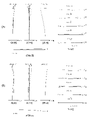
- FIG. 1 is a diagram showing a lens configuration of a variable power optical system according to a first example
- FIG. FIGS. 2A and 2B are diagrams of various aberrations in the wide-angle end state and the telephoto end state of the variable power optical system according to the first embodiment, respectively, when focusing on infinity.
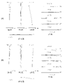
- FIG. 10 is a diagram showing a lens configuration of a variable-magnification optical system according to a second example
- 4A and 4B are diagrams of various aberrations in the wide-angle end state and the telephoto end state of the variable power optical system according to the second embodiment, respectively, when focusing on infinity.
- FIG. 11 is a diagram showing a lens configuration of a variable-magnification optical system according to a third example; 6A and 6B are diagrams of various aberrations in the wide-angle end state and the telephoto end state of the variable power optical system according to the third embodiment, respectively, when focusing on infinity.
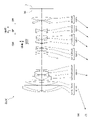
- FIG. 11 is a diagram showing a lens configuration of a variable-magnification optical system according to a fourth example; 8A and 8B are diagrams of various aberrations in the wide-angle end state and the telephoto end state of the variable power optical system according to the fourth embodiment, respectively, when focusing on infinity. It is a figure which shows the structure of the camera provided with the variable-magnification optical system which concerns on each embodiment.
- 4 is a flow chart showing a method of manufacturing the variable magnification optical system according to the first embodiment; 9 is a flow chart showing a method of manufacturing a variable magnification optical system according to the second embodiment;
- the camera 1 comprises a main body 2 and a photographing lens 3 attached to the main body 2.
- the main body 2 includes an imaging device 4 , a main body control section (not shown) that controls the operation of the digital camera, and a liquid crystal screen 5 .
- the taking lens 3 includes a variable magnification optical system ZL consisting of a plurality of lens groups, and a lens position control mechanism (not shown) that controls the position of each lens group.
- the lens position control mechanism includes a sensor that detects the position of the lens group, a motor that moves the lens group back and forth along the optical axis, a control circuit that drives the motor, and the like.
- variable magnification optical system ZL of the photographing lens 3 The light from the subject is condensed by the variable magnification optical system ZL of the photographing lens 3 and reaches the image plane I of the imaging device 4 .
- the light from the subject reaching the image plane I is photoelectrically converted by the imaging device 4 and recorded as digital image data in a memory (not shown).
- the digital image data recorded in the memory can be displayed on the liquid crystal screen 5 according to the user's operation.
- This camera may be a mirrorless camera or a single-lens reflex type camera having a quick return mirror.
- the variable power optical system ZL shown in FIG. 9 schematically shows the variable power optical system provided in the taking lens 3, and the lens configuration of the variable power optical system ZL is not limited to this configuration. No.
- a variable power optical system ZL(1) which is an example of a variable power optical system (zoom lens) ZL according to the first embodiment, includes positive lenses arranged in order from the object side along an optical axis. a first lens group G1 having refractive power, a second lens group G2 having negative refractive power, a third lens group G3 having positive refractive power, and a fourth lens group G4 having negative refractive power; and a fifth lens group G5 having negative refractive power.
- the fourth lens group G4 is a focusing lens group GF that moves along the optical axis during focusing.
- variable power optical system ZL satisfies the following conditional expression (1). 0.11 ⁇ f4/f5 ⁇ 0.70 (1) where f4 is the focal length of the fourth lens group G4 f5 is the focal length of the fifth lens group G5
- variable-magnification optical system ZL may be the variable power optical system ZL(2) shown in FIG. 3 or the variable power optical system ZL(3) shown in FIG.
- Conditional expression (1) defines an appropriate relationship between the focal length of the fourth lens group G4 and the focal length of the fifth lens group G5.
- conditional expression (1) When the corresponding value of conditional expression (1) exceeds the upper limit, the focal length of the fourth lens group G4 becomes longer, and the movement amount of the fourth lens group G4, which is the focusing lens group, during focusing becomes larger. , it becomes difficult to suppress variations in spherical aberration, coma, and curvature of field during focusing. Further, since the focal length of the fifth lens group G5 is shortened, it becomes difficult to correct the curvature of field generated in the fifth lens group G5. By setting the upper limit of conditional expression (1) to 0.65, and further to 0.60, the effects of this embodiment can be made more reliable.
- conditional expression (1) When the corresponding value of conditional expression (1) is below the lower limit, the focal length of the fourth lens group G4 is shortened, thereby correcting spherical aberration, coma and field curvature occurring in the fourth lens group G4. becomes difficult. In addition, since the focal length of the fifth lens group G5 becomes longer, the correction effect of the curvature of field by the fifth lens group G5 becomes smaller, making it difficult to obtain good optical performance.
- the lower limit of conditional expression (1) By setting the lower limit of conditional expression (1) to 0.15, and further to 0.20, the effects of this embodiment can be made more reliable.
- variable power optical system ZL preferably satisfies the following conditional expression (2). 0.01 ⁇ (-f4)/f3 ⁇ 5.00 (2) where f3 is the focal length of the third lens group G3
- Conditional expression (2) defines an appropriate relationship between the focal length of the fourth lens group G4 and the focal length of the third lens group G3. By satisfying conditional expression (2), spherical aberration, coma, and curvature of field can be satisfactorily corrected.
- conditional expression (2) exceeds the upper limit, the focal length of the fourth lens group G4 becomes longer, and the amount of movement of the fourth lens group G4, which is the focusing lens group, during focusing becomes larger. , it becomes difficult to suppress variations in spherical aberration, coma, and curvature of field during focusing. Further, since the focal length of the third lens group G3 is shortened, it becomes difficult to correct spherical aberration and coma aberration occurring in the third lens group G3. This embodiment can effect can be made more reliable.
- conditional expression (2) When the corresponding value of conditional expression (2) is below the lower limit, the focal length of the fourth lens group G4 is shortened, thereby correcting spherical aberration, coma and field curvature occurring in the fourth lens group G4. becomes difficult.
- the focal length of the third lens group G3 increases, the amount of movement of the third lens group G3 during zooming increases, making it difficult to suppress fluctuations in spherical aberration and coma during zooming. Become.
- the lower limit of conditional expression (2) By setting the lower limit of conditional expression (2) to 0.05, 1.00, 1.25, and further to 1.50, the effect of this embodiment can be made more reliable.
- variable power optical system ZL preferably satisfies the following conditional expression (3). 0.01 ⁇ f3/(-f5) ⁇ 1.00 (3) where f3 is the focal length of the third lens group G3
- Conditional expression (3) defines an appropriate relationship between the focal length of the third lens group G3 and the focal length of the fifth lens group G5.
- conditional expression (3) exceeds the upper limit, the focal length of the third lens group G3 becomes longer, so that the amount of movement of the third lens group G3 during zooming increases, resulting in an increase in the amount of movement of the third lens group G3 during zooming. It becomes difficult to suppress variations in spherical aberration and coma. Further, since the focal length of the fifth lens group G5 is shortened, it becomes difficult to correct the curvature of field generated in the fifth lens group G5. By setting the upper limit of conditional expression (3) to 0.75, 0.50, 0.29, and further to 0.25, the effects of this embodiment can be made more reliable.
- conditional expression (3) When the corresponding value of conditional expression (3) is below the lower limit, the focal length of the third lens group G3 becomes short, making it difficult to correct spherical aberration and coma aberration occurring in the third lens group G3. . In addition, since the focal length of the fifth lens group G5 becomes longer, the correction effect of the curvature of field by the fifth lens group G5 becomes smaller, making it difficult to obtain good optical performance.
- the lower limit of conditional expression (3) to 0.05, and further to 0.09, the effect of this embodiment can be made more reliable.
- variable power optical system ZL preferably satisfies the following conditional expression (4). 0.01 ⁇ f3/(-f45t) ⁇ 2.00 (4) where f3 is the focal length of the third lens group G3 f45t is the combined focal length of the fourth lens group G4 and the fifth lens group G5 in the telephoto end state
- Conditional expression (4) defines an appropriate relationship between the focal length of the third lens group G3 and the combined focal length of the fourth lens group G4 and the fifth lens group G5 in the telephoto end state.
- conditional expression (4) exceeds the upper limit, the focal length of the third lens group G3 becomes longer, so that the amount of movement of the third lens group G3 during zooming increases, resulting in an increase in the amount of movement of the third lens group G3 during zooming. It becomes difficult to suppress variations in spherical aberration and coma.
- the combined focal length of the fourth lens group G4 and the fifth lens group G5 in the telephoto end state is shortened, spherical aberration, coma aberration, and curvature of field generated in the fourth lens group G4 and the fifth lens group G5 becomes difficult to correct.
- conditional expression (4) When the corresponding value of conditional expression (4) is below the lower limit, the focal length of the third lens group G3 becomes short, making it difficult to correct spherical aberration and coma aberration occurring in the third lens group G3. .
- the combined focal length of the fourth lens group G4 and the fifth lens group G5 in the telephoto end state becomes long, the amount of movement of the fourth lens group G4 and the fifth lens group G5 during zooming becomes large. It becomes difficult to suppress fluctuations in spherical aberration, coma, and curvature of field when magnifying.
- the lower limit of conditional expression (4) By setting the lower limit of conditional expression (4) to 0.10, 0.25, 0.33, 0.45, and further to 0.56, the effects of this embodiment can be made more reliable. .
- variable power optical system ZL preferably satisfies the following conditional expression (5). 0.01 ⁇ 5t/ ⁇ 5w ⁇ 2.00 (5) where ⁇ 5t: lateral magnification of the fifth lens group G5 in the telephoto end state ⁇ 5w: lateral magnification of the fifth lens group G5 in the wide-angle end state
- Conditional expression (5) defines an appropriate relationship between the lateral magnification of the fifth lens group G5 in the telephoto end state and the lateral magnification of the fifth lens group G5 in the wide-angle end state. Satisfying the conditional expression (5) is preferable because it is possible to obtain a variable power optical system having good optical performance while realizing reduction in size and weight.
- the upper limit of conditional expression (5) to 1.80, 1.65, 1.55, 1.49, and further to 1.30, the effects of this embodiment can be made more reliable.
- the lower limit of conditional expression (5) By setting the lower limit of conditional expression (5) to 0.10, 0.25, 0.50, 0.75, 0.90, and further to 1.07, the effects of the present embodiment can be made more reliable. can do.
- variable power optical system ZL preferably satisfies the following conditional expression (6). 0.01 ⁇ Bfw/fw ⁇ 0.95 (6)
- Bfw back focus of the variable-magnification optical system ZL in the wide-angle end state
- fw focal length of the variable-magnification optical system ZL in the wide-angle end state
- Conditional expression (6) defines an appropriate relationship between the back focus of the variable power optical system ZL in the wide-angle end state and the focal length of the variable power optical system ZL in the wide-angle end state.
- the back focus of the variable power optical system ZL is the air-equivalent distance on the optical axis from the lens surface closest to the image plane side to the image plane I of the variable power optical system ZL.
- Satisfying the conditional expression (6) is preferable because it is possible to obtain a variable magnification optical system having good optical performance while achieving a reduction in size and weight.
- variable power optical system ZL it is desirable that the fifth lens group G5 consist of two lenses. Thereby, it is possible to satisfactorily suppress fluctuations in curvature of field during zooming.
- the third lens group G3 has a lens that satisfies the following conditional expression (7). 75.00 ⁇ 3L (7) where ⁇ 3L: the Abbe number of the lens in the third lens group G3
- Conditional expression (7) defines an appropriate range for the Abbe numbers of the lenses in the third lens group G3. If the third lens group G3 has a lens that satisfies the conditional expression (7), it is preferable because a variable magnification optical system having good optical performance with corrected chromatic aberration can be obtained. By setting the lower limit of conditional expression (7) to 77.00, 80.00, and further to 82.00, the effect of this embodiment can be made more reliable.
- the third lens group G3 has a vibration reduction group GVR that is movable so as to have a displacement component in the direction perpendicular to the optical axis. It is desirable to have As a result, it is possible to obtain a variable-magnification optical system that achieves a reduction in size and weight and that has excellent anti-vibration performance, which is preferable.
- variable power optical system ZL preferably satisfies the following conditional expression (8). 0.01 ⁇ f3/fVR ⁇ 2.00 (8) where f3: focal length of the third lens group G3 fVR: focal length of the anti-vibration group GVR
- Conditional expression (8) defines an appropriate relationship between the focal length of the third lens group G3 and the focal length of the anti-vibration group GVR. Satisfying conditional expression (8) makes it possible to suppress eccentric coma and asymmetric curvature of field when correcting image blur, and to obtain good vibration reduction performance.
- conditional expression (8) When the corresponding value of conditional expression (8) exceeds the upper limit value, the focal length of the anti-vibration group GVR is shortened. Curvature is difficult to suppress.
- the upper limit of conditional expression (8) By setting the upper limit of conditional expression (8) to 1.75, 1.50, 1.25, and further to 1.00, the effect of this embodiment can be made more reliable.
- conditional expression (8) When the corresponding value of conditional expression (8) is below the lower limit, the focal length of the anti-vibration group GVR becomes longer, so that the amount of movement of the anti-vibration group GVR when correcting image blur increases, causing eccentric coma, It becomes difficult to suppress asymmetric curvature of field.
- the lower limit of conditional expression (8) By setting the lower limit of conditional expression (8) to 0.10, 0.30, 0.40, and further to 0.45, the effect of this embodiment can be made more reliable.
- variable magnification optical system ZL it is desirable that the anti-vibration group GVR is arranged closest to the image plane side of the third lens group G3. As a result, it is possible to obtain a good anti-vibration performance while maintaining the optical performance of the variable magnification optical system.
- a variable power optical system ZL(1) as an example of the variable power optical system (zoom lens) ZL according to the second embodiment includes positive lenses arranged in order from the object side along the optical axis.
- It consists of a focusing lens group GF and a rear group GR having at least one lens group.
- the focusing lens group GF moves along the optical axis during focusing.
- variable-magnification optical system ZL satisfies the following conditional expression (9) and the above-described conditional expression (6). 0.30 ⁇ (-f2)/fMt ⁇ 0.80 (9) 0.01 ⁇ Bfw/fw ⁇ 0.95 (6)
- f2 focal length of second lens group
- G2 fMt: focal length of intermediate group GM in telephoto end state
- Bfw back focus of variable power optical system ZL in wide-angle end state
- fw focal length of variable power optical system ZL in wide-angle end state
- variable-magnification optical system ZL may be the variable power optical system ZL(2) shown in FIG. 3, the variable power optical system ZL(3) shown in FIG. 5, or the variable power optical system ZL(3) shown in FIG. System ZL(4) may also be used.
- Conditional expression (9) defines an appropriate relationship between the focal length of the second lens group G2 and the focal length of the intermediate group GM in the telephoto end state.
- conditional expression (9) exceeds the upper limit value, the focal length of the second lens group G2 increases, so that the amount of movement of the second lens group G2 during zooming increases, resulting in a large amount of movement during zooming. It becomes difficult to suppress variations in spherical aberration, coma, and curvature of field. In addition, since the focal length of the middle group GM in the telephoto end state becomes short, it becomes difficult to correct spherical aberration and coma generated in the middle group GM. By setting the upper limit of conditional expression (9) to 0.75, and further to 0.70, the effects of this embodiment can be made more reliable.
- conditional expression (9) When the corresponding value of conditional expression (9) is below the lower limit, the focal length of the second lens group G2 is shortened, thereby correcting spherical aberration, coma aberration, and curvature of field generated in the second lens group G2. becomes difficult.
- the longer the focal length of the middle group GM in the telephoto end state the greater the amount of movement of the middle group GM during zooming, making it difficult to suppress fluctuations in spherical aberration and coma during zooming. Become.
- the lower limit of conditional expression (9) By setting the lower limit of conditional expression (9) to 0.40, and further to 0.50, the effects of this embodiment can be made more reliable.
- conditional expression (6) defines an appropriate relationship between the back focus of the variable power optical system ZL in the wide-angle end state and the focal length of the variable power optical system ZL in the wide-angle end state. Satisfying the conditional expression (6) is preferable because it is possible to obtain a variable magnification optical system having good optical performance while achieving a reduction in size and weight.
- the upper limit of conditional expression (6) 0.90, 0.85, 0.80, 0.78, 0.75, 0.65, and further to 0.58, the effect of this embodiment can be further enhanced. can be made certain.
- the lower limit of conditional expression (6) By setting the lower limit of conditional expression (6) to 0.10, 0.30, 0.40, and further 0.50, the effect of this embodiment can be made more reliable.
- variable power optical system ZL preferably satisfies the following conditional expression (10). 0.01 ⁇ (-fF)/fMt ⁇ 5.00 (10) where fF is the focal length of the focusing lens group GF
- Conditional expression (10) defines an appropriate relationship between the focal length of the focusing lens group GF and the focal length of the intermediate group GM in the telephoto end state. By satisfying conditional expression (10), spherical aberration, coma, and curvature of field can be satisfactorily corrected.
- conditional expression (10) exceeds the upper limit value, the focal length of the focusing lens group GF becomes long, so that the amount of movement of the focusing lens group GF during focusing becomes large. It becomes difficult to suppress variations in spherical aberration, coma, and curvature of field. In addition, since the focal length of the middle group GM in the telephoto end state becomes short, it becomes difficult to correct spherical aberration and coma generated in the middle group GM.
- the upper limit of conditional expression (10) By setting the upper limit of conditional expression (10) to 4.50, 4.00, 3.50, 3.00, and further to 2.30, the effects of this embodiment can be made more reliable. .
- conditional expression (10) When the corresponding value of conditional expression (10) is below the lower limit, the focal length of the focusing lens group GF becomes short, thereby correcting spherical aberration, coma aberration, and curvature of field generated in the focusing lens group GF. becomes difficult.
- the longer the focal length of the middle group GM in the telephoto end state the greater the amount of movement of the middle group GM during zooming, making it difficult to suppress fluctuations in spherical aberration and coma during zooming. Become.
- the lower limit of conditional expression (10) By setting the lower limit of conditional expression (10) to 0.10, 0.50, 0.70, 1.00, 1.25, and further to 1.50, the effects of the present embodiment can be made more reliable. can do.
- variable power optical system ZL preferably satisfies the following conditional expression (11). 0.01 ⁇ fMt/
- Conditional expression (11) defines an appropriate relationship between the focal length of the middle group GM in the telephoto end state and the focal length of the rear group GR in the telephoto end state.
- conditional expression (11) exceeds the upper limit value, the focal length of the middle group GM in the telephoto end state becomes longer, so that the amount of movement of the middle group GM during zooming increases, resulting in an increase in the amount of movement of the middle group GM during zooming. It becomes difficult to suppress variations in spherical aberration and coma. Further, since the focal length of the rear group GR becomes short in the telephoto end state, it becomes difficult to correct the curvature of field generated in the rear group GR. By setting the upper limit of conditional expression (11) to 0.85, 0.70, 0.60, 0.50, 0.35, and further to 0.25, the effects of the present embodiment are more reliable. can do.
- conditional expression (11) If the corresponding value of conditional expression (11) is below the lower limit, the focal length of the middle group GM in the telephoto end state becomes short, making it difficult to correct spherical aberration and coma generated in the middle group GM. . In addition, since the focal length of the rear group GR becomes long in the telephoto end state, the correction effect of the field curvature by the rear group GR becomes small, making it difficult to obtain good optical performance. By setting the lower limit of conditional expression (11) to 0.03, and further to 0.04, the effects of this embodiment can be made more reliable.
- variable power optical system ZL preferably satisfies the following conditional expression (12). 0.01 ⁇ (-fF)/
- Conditional expression (12) defines an appropriate relationship between the focal length of the focusing lens group GF and the focal length of the rear group GR in the telephoto end state.
- conditional expression (12) exceeds the upper limit value, the focal length of the focusing lens group GF becomes longer, and the amount of movement of the focusing lens group GF at the time of focusing becomes larger. It becomes difficult to suppress variations in spherical aberration, coma, and curvature of field. Further, since the focal length of the rear group GR becomes short in the telephoto end state, it becomes difficult to correct the curvature of field generated in the rear group GR.
- the upper limit of conditional expression (12) By setting the upper limit of conditional expression (12) to 0.85, 0.75, 0.65, 0.60, and further to 0.55, the effects of this embodiment can be made more reliable. .
- conditional expression (12) When the corresponding value of conditional expression (12) is below the lower limit, the focal length of the focusing lens group GF becomes short, thereby correcting spherical aberration, coma aberration, and curvature of field generated in the focusing lens group GF. becomes difficult. In addition, since the focal length of the rear group GR becomes long in the telephoto end state, the correction effect of the field curvature by the rear group GR becomes small, making it difficult to obtain good optical performance. By setting the lower limit of conditional expression (12) to 0.06, and further to 0.075, the effect of this embodiment can be made more reliable.
- variable power optical system ZL preferably satisfies the following conditional expression (13). 0.01 ⁇ fMt/(-fFRt) ⁇ 1.00 (13) where fFRt is the combined focal length of at least one lens group of the focusing lens group GF and the rear group GR in the telephoto end state.
- Conditional expression (13) defines an appropriate relationship between the focal length of the intermediate group GM in the telephoto end state and the combined focal length of at least one lens group of the focusing lens group GF and the rear group GR in the telephoto end state. It is. By satisfying conditional expression (13), spherical aberration, coma, and curvature of field can be satisfactorily corrected.
- conditional expression (13) exceeds the upper limit value, the focal length of the middle group GM in the telephoto end state becomes long, so that the amount of movement of the middle group GM during zooming increases, resulting in an increase in the amount of movement of the middle group GM during zooming. It becomes difficult to suppress variations in spherical aberration and coma.
- the combined focal length of at least one of the focusing lens group GF and the rear group GR becomes short in the telephoto end state, spherical aberration occurs in the lens group arranged closer to the image plane than the intermediate group GM. , coma, and field curvature.
- conditional expression (13) If the corresponding value of conditional expression (13) is below the lower limit, the focal length of the intermediate group GM in the telephoto end state becomes short, making it difficult to correct spherical aberration and coma generated in the intermediate group GM. .
- the lens group arranged closer to the image plane than the intermediate group GM can The amount of movement increases, and it becomes difficult to suppress variations in spherical aberration, coma, and curvature of field during zooming.
- the lower limit of conditional expression (13) By setting the lower limit of conditional expression (13) to 0.10, 0.25, 0.35, and further to 0.45, the effect of this embodiment can be made more reliable.
- variable power optical system ZL preferably satisfies the following conditional expression (14). 0.10 ⁇ Rt/ ⁇ Rw ⁇ 2.00 (14) where ⁇ Rt: lateral magnification of the rear group GR in the telephoto end state ⁇ Rw: lateral magnification of the rear group GR in the wide-angle end state
- Conditional expression (14) defines an appropriate relationship between the lateral magnification of the rear group GR in the telephoto end state and the lateral magnification of the rear group GR in the wide-angle end state. Satisfying the conditional expression (14) is preferable because it is possible to obtain a variable power optical system having good optical performance while achieving a reduction in size and weight.
- the upper limit of conditional expression (14) to 1.80, 1.65, 1.50, 1.45, 1.35, and further to 1.25, the effects of the present embodiment are more reliable. can do.
- the lower limit of conditional expression (14) to 0.10, 0.25, 0.40, 0.50, and further to 0.70, the effects of this embodiment can be made more reliable. .
- variable power optical system ZL it is desirable that the rear group GR consist of two lenses. Thereby, it is possible to satisfactorily suppress fluctuations in curvature of field during zooming.
- variable power optical system ZL it is desirable that the intermediate group GM consist of one lens group. This is preferable because it is possible to obtain a variable magnification optical system having good optical performance while realizing a reduction in size and weight.
- variable power optical system ZL it is desirable that the rear group GR consist of one lens group. This is preferable because it is possible to obtain a variable magnification optical system having good optical performance while realizing a reduction in size and weight.
- variable magnification optical system ZL it is desirable that the rear group GR have negative refractive power. This is preferable because it is possible to obtain a variable magnification optical system having good optical performance while realizing a reduction in size and weight.
- the intermediate group GM has a lens that satisfies the following conditional expression (15). 75.00 ⁇ ML (15) where ⁇ ML: the Abbe number of the lens in the middle group GM
- Conditional expression (15) defines an appropriate range for the Abbe number of the lens in the intermediate group GM. If the middle group GM has a lens that satisfies the conditional expression (15), it is preferable because a variable magnification optical system having good optical performance in which chromatic aberration is corrected can be obtained. By setting the lower limit of conditional expression (15) to 76.00, 77.50, 78.50, and further to 80.00, the effect of this embodiment can be made more reliable.
- variable-magnification optical system ZL it is desirable that the intermediate group GM has, as a part of the intermediate group GM, a vibration reduction group GVR that can move so as to have a displacement component in the direction perpendicular to the optical axis. .
- a vibration reduction group GVR that can move so as to have a displacement component in the direction perpendicular to the optical axis.
- variable power optical system ZL preferably satisfies the following conditional expression (16). 0.01 ⁇ fMt/fVR ⁇ 1.00 (16) where fVR is the focal length of the anti-vibration group GVR
- Conditional expression (16) defines an appropriate relationship between the focal length of the middle group GM and the focal length of the anti-vibration group GVR in the telephoto end state. Satisfying conditional expression (16) makes it possible to suppress eccentric coma and asymmetric curvature of field when correcting image blur, and to obtain good image stabilization performance.
- conditional expression (16) exceeds the upper limit value, the focal length of the anti-vibration group GVR is shortened. Curvature is difficult to suppress.
- conditional expression (16) When the corresponding value of conditional expression (16) is below the lower limit, the focal length of the anti-vibration group GVR becomes longer, so that the amount of movement of the anti-vibration group GVR when correcting image blur increases. It becomes difficult to suppress asymmetric curvature of field.
- the lower limit of conditional expression (16) By setting the lower limit of conditional expression (16) to 0.10, 0.25, 0.45, and further to 0.60, the effect of this embodiment can be made more reliable.
- variable magnification optical system ZL it is desirable that the vibration reduction group GVR is arranged closest to the image plane side of the intermediate group GM. As a result, it is possible to obtain a good anti-vibration performance while maintaining the optical performance of the variable magnification optical system.
- variable magnification optical system ZL according to the first embodiment and the second embodiment satisfy the following conditional expression (17). 0.01 ⁇ fVR/(-fF) ⁇ 2.50 (17) where fVR: focal length of anti-vibration group GVR fF: focal length of focusing lens group GF
- Conditional expression (17) defines an appropriate relationship between the focal length of the anti-vibration group GVR and the focal length of the focusing lens group GF. Satisfying conditional expression (17) makes it possible to suppress eccentric coma aberration and asymmetric curvature of field when correcting image blur, and to obtain excellent image stabilization performance.
- conditional expression (17) exceeds the upper limit value, the focal length of the anti-vibration group GVR becomes long, and the amount of movement of the anti-vibration group GVR when correcting image blur increases, resulting in eccentric coma aberration, It becomes difficult to suppress asymmetric curvature of field.
- the focal length of the focusing lens group GF is shortened, it becomes difficult to correct spherical aberration, coma aberration, and curvature of field generated in the focusing lens group GF.
- conditional expression (17) When the corresponding value of conditional expression (17) is below the lower limit, the focal length of the anti-vibration group GVR is shortened, and decentration coma generated in the anti-vibration group GVR when correcting image blur and an asymmetric image plane Curvature is difficult to suppress. In addition, by increasing the focal length of the focusing lens group GF, the amount of movement of the focusing lens group GF during focusing becomes large, suppressing variations in spherical aberration, coma, and field curvature during focusing. becomes difficult. By setting the lower limit of conditional expression (17) to 0.10, 0.40, 0.63, 0.70, and further to 1.00, the effect of each embodiment can be made more reliable. .
- the anti-vibration group GVR preferably consists of two lenses. This makes it possible to suppress variations in chromatic aberration when image blur is corrected.
- variable power optical system ZL preferably satisfies the following conditional expression (18). 0.01 ⁇ (-f2)/f1 ⁇ 1.00 (18) where f1: focal length of the first lens group G1 f2: focal length of the second lens group G2
- Conditional expression (18) defines an appropriate relationship between the focal length of the second lens group G2 and the focal length of the first lens group G1.
- conditional expression (18) exceeds the upper limit value, the focal length of the second lens group G2 becomes longer, so that the amount of movement of the second lens group G2 during zooming increases. It becomes difficult to suppress variations in spherical aberration, coma, and curvature of field. Further, since the focal length of the first lens group G1 is shortened, it becomes difficult to correct spherical aberration, coma aberration, and curvature of field generated in the first lens group G1.
- the upper limit of conditional expression (18) By setting the upper limit of conditional expression (18) to 0.75, 0.50, 0.30, 0.25, 0.20, and further to 0.18, the effect of each embodiment can be more assured. can do.
- conditional expression (18) When the corresponding value of conditional expression (18) is below the lower limit, the focal length of the second lens group G2 is shortened, thereby correcting spherical aberration, coma and field curvature occurring in the second lens group G2. becomes difficult. In addition, since the focal length of the first lens group G1 increases, the amount of movement of the first lens group G1 during zooming increases, suppressing variations in spherical aberration, coma, and curvature of field during zooming. becomes difficult. By setting the lower limit of conditional expression (18) to 0.05, 0.10, and further 0.16, the effect of each embodiment can be made more reliable.
- variable power optical system ZL preferably satisfies the following conditional expression (19). 0.01 ⁇ TLt/ft ⁇ 2.00 (19) where TLt is the total length of the variable magnification optical system ZL in the telephoto end state ft is the focal length of the variable magnification optical system ZL in the telephoto end state
- Conditional expression (19) defines an appropriate relationship between the total length of the variable power optical system ZL in the telephoto end state and the focal length of the variable power optical system ZL in the telephoto end state.
- the total length of the variable-magnification optical system ZL is the distance on the optical axis from the lens surface closest to the object side of the variable-magnification optical system ZL to the image plane I
- variable power optical system ZL preferably satisfies the following conditional expression (20). 0.01 ⁇ Ft/ ⁇ Fw ⁇ 2.00 (20) where ⁇ Ft: lateral magnification of the focusing lens group GF in the telephoto end state ⁇ Fw: lateral magnification of the focusing lens group GF in the wide-angle end state
- Conditional expression (20) defines an appropriate relationship between the lateral magnification of the focusing lens group GF in the telephoto end state and the lateral magnification of the focusing lens group GF in the wide-angle end state. Satisfying the conditional expression (20) is preferable because it is possible to obtain a variable-power optical system that is compact and lightweight and has good optical performance.
- the upper limit of conditional expression (20) to 1.80, 1.65, 1.50, and further to 1.35, the effect of each embodiment can be made more reliable.
- the lower limit of conditional expression (20) to 0.10, 0.50, 0.85, 0.90, 1.20, and further to 1.21, the effect of each embodiment can be more assured. can do.
- variable magnification optical system ZL it is desirable that the focusing lens group GF consist of two lenses. This makes it possible to suppress variations in chromatic aberration during focusing.
- the first lens group G1 has a lens that satisfies the following conditional expression (21). 75.00 ⁇ 1L (21) where ⁇ 1L: the Abbe number of the lens in the first lens group G1
- Conditional expression (21) defines an appropriate range for the Abbe numbers of the lenses in the first lens group G1. If the first lens group G1 has a lens that satisfies the conditional expression (21), it is preferable because a variable magnification optical system having good optical performance with corrected chromatic aberration can be obtained. By setting the lower limit of conditional expression (21) to 76.00, 77.50, 78.50, and further to 80.00, the effect of this embodiment can be made more reliable.
- a method for manufacturing the variable power optical system ZL according to the first embodiment will be outlined with reference to FIG.
- a fourth lens group G4 having negative refractive power and a fifth lens group G5 having negative refractive power are arranged (step ST1).
- the fourth lens group G4 is configured to be a focusing lens group that moves along the optical axis during focusing (step ST3).
- each lens is arranged in the lens barrel so as to satisfy at least the conditional expression (1) (step ST4). According to such a manufacturing method, it is possible to manufacture a variable power optical system having good optical performance while achieving a reduction in size and weight.
- a method for manufacturing the variable power optical system ZL according to the second embodiment will be outlined with reference to FIG.
- a middle group GM having power, a focusing lens group GF having negative refractive power, and a rear group GR having at least one lens group are arranged (step ST11).
- it is configured so that the distance between adjacent lens groups changes during zooming (step ST12).
- the focusing lens group GF is configured to move along the optical axis during focusing (step ST13).
- each lens is arranged in the lens barrel so as to satisfy at least the conditional expressions (9) and (6) (step ST14). According to such a manufacturing method, it is possible to manufacture a variable power optical system having good optical performance while achieving a reduction in size and weight.
- variable-magnification optical system ZL according to the example of each embodiment will be described based on the drawings.
- 1, 3, 5, and 7 are cross-sectional views showing configurations and refractive power distributions of variable magnification optical systems ZL ⁇ ZL(1) to ZL(4) ⁇ according to first to fourth examples.
- Examples corresponding to the first embodiment are the first to third examples
- examples corresponding to the second embodiment are the first to fourth examples.
- the moving direction of the focusing lens group when focusing on a short distance object from infinity is indicated by an arrow together with the word "focus”.
- the moving direction of the anti-vibration group when correcting image blur is indicated by an arrow together with the word "vibration isolation”.
- each lens group is represented by a combination of symbol G and a number, and each lens is represented by a combination of symbol L and a number.
- the lens groups and the like are represented independently using combinations of symbols and numerals for each embodiment. Therefore, even if the same reference numerals and symbols are used between the embodiments, it does not mean that they have the same configuration.
- f is the focal length of the entire lens system
- FNO is the F number
- ⁇ is the half angle of view (unit is ° (degrees))
- Y is the image height.
- TL indicates the distance obtained by adding Bf (back focus) to the distance on the optical axis from the lens surface closest to the object side to the lens surface closest to the image plane in the variable power optical system when focusing on infinity, where Bf is infinity. It shows the distance (air conversion distance) on the optical axis from the lens surface closest to the image plane to the image plane in the variable-magnification optical system when focusing at a far distance.
- fM indicates the focal length of the middle group
- fR indicates the focal length of the rear group. Note that these values are shown for each of the zooming states of the wide-angle end (W) and the telephoto end (T).
- fF indicates the focal length of the focusing lens group.
- fVR indicates the focal length of the anti-vibration group.
- fFRt represents the combined focal length of at least one of the in-focus lens group and the rear group in the telephoto end state.
- f45t represents the combined focal length of the fourth lens group and the fifth lens group in the telephoto end state.
- ⁇ Fw represents the lateral magnification of the focusing lens group in the wide-angle end state.
- ⁇ Ft indicates the lateral magnification of the focusing lens group in the telephoto end state.
- ⁇ Rw indicates the lateral magnification of the rear group in the wide-angle end state.
- ⁇ Rt indicates the lateral magnification of the rear group in the telephoto end state.
- ⁇ 4w indicates the lateral magnification of the fourth lens group in the wide-angle end state.
- ⁇ 4t indicates the lateral magnification of the fourth lens group in the telephoto end state.
- ⁇ 5w indicates the lateral magnification of the fifth lens group in the wide-angle end state.
- ⁇ 5t indicates the lateral magnification of the fifth lens group in the telephoto end state.
- the surface number indicates the order of the optical surfaces from the object side along the direction in which light rays travel
- R is the radius of curvature of each optical surface (the surface whose center of curvature is located on the image side). is a positive value)
- D is the distance on the optical axis from each optical surface to the next optical surface (or image plane)
- nd is the refractive index for the d-line of the material of the optical member
- ⁇ d is the optical
- the Abbe numbers of the materials of the members are shown with reference to the d-line.
- the radius of curvature “ ⁇ ” indicates a plane or an aperture
- (diaphragm S) indicates an aperture diaphragm S, respectively.
- the [Variable Spacing Data] table shows the surface spacing at surface number i for which the surface spacing is (Di) in the [Lens Specifications] table.
- the [Variable Spacing Data] table shows the surface spacing in the infinity focused state and the surface spacing in the close distance focused state.
- the [Lens group data] table shows the starting surface (surface closest to the object side) and focal length of each lens group.
- mm is generally used for the focal length f, radius of curvature R, surface spacing D, and other lengths in all specifications below, but the optical system is proportionally enlarged. Alternatively, it is not limited to this because equivalent optical performance can be obtained even if it is proportionally reduced.
- FIG. 1 is a diagram showing the lens configuration of a variable magnification optical system according to the first embodiment.
- the variable power optical system ZL(1) according to the first example includes a first lens group G1 having positive refractive power and a second lens group having negative refractive power, which are arranged in order from the object side along the optical axis. It consists of a group G2, a third lens group G3 having positive refractive power, a fourth lens group G4 having negative refractive power, and a fifth lens group G5 having negative refractive power.
- the first lens group G1 moves along the optical axis toward the object side
- the second lens group G2 moves along the optical axis once to the image plane.
- the third lens group G3, the fourth lens group G4, and the fifth lens group G5 move along the optical axis toward the object side, and the distance between the adjacent lens groups becomes Change.
- An aperture diaphragm S is arranged between the second lens group G2 and the third lens group G3, and during zooming, the aperture diaphragm S moves along the optical axis together with the third lens group G3.
- the sign (+) or (-) attached to each lens group symbol indicates the refractive power of each lens group, and this is the same for all the following examples.
- the first lens group G1 includes a cemented lens constructed by a negative meniscus lens L11 having a convex surface facing the object side and a biconvex positive lens L12 arranged in order from the object side along the optical axis, and a cemented lens having a convex surface facing the object side. and a positive meniscus lens L13.
- the second lens group G2 includes a negative meniscus lens L21 having a convex surface facing the object side, a biconcave negative lens L22, and a biconvex positive lens L23, which are arranged in order from the object side along the optical axis. and a negative meniscus lens L24 having a concave surface facing the object side.
- the third lens group G3 includes a biconvex positive lens L31, a biconvex positive lens L32, and a negative meniscus lens L33 having a convex surface facing the object side, which are arranged in order from the object side along the optical axis. It is composed of a cemented lens to which a convex positive lens L34 is cemented, and a cemented lens to which a biconvex positive lens L35 and a negative meniscus lens L36 having a concave surface facing the object side are cemented.
- the positive lens L31 is a hybrid lens formed by providing a resin layer on the object-side surface of a glass lens body.
- the object-side surface of the resin layer is aspherical, and the positive lens L31 is a compound aspherical lens.
- the surface number 15 is the object side surface of the resin layer
- the surface number 16 is the image side surface of the resin layer and the object side surface of the lens body (surface where both are joined)
- Numeral 17 indicates the image plane side surface of the lens body.
- the positive lens L35 is also a hybrid lens that is configured by providing a resin layer on the object-side surface of the glass lens body.
- the object-side surface of the resin layer is aspherical, and the positive lens L35 is also a compound aspherical lens.
- the surface number 23 is the object side surface of the resin layer
- the surface number 24 is the image side surface of the resin layer and the object side surface of the lens body (surface where both are joined)
- Numeral 25 indicates the image plane side surface of the lens body (the surface cemented with the negative meniscus lens L36).
- the fourth lens group G4 is composed of a cemented lens in which a biconvex positive lens L41 and a biconcave negative lens L42 are cemented in order from the object side.
- the fifth lens group G5 is composed of a negative meniscus lens L51 with a concave surface facing the object side and a positive meniscus lens L52 with a concave surface facing the object side, which are arranged in order from the object side along the optical axis.
- An image plane I is arranged on the image side of the fifth lens group G5.
- a parallel plate PP is arranged between the fifth lens group G5 and the image plane I.
- the third lens group G3 constitutes an intermediate group GM having positive refractive power as a whole.
- the positive lens L35 and the negative meniscus lens L36 arranged closest to the image plane in the third lens group G3 are movable so as to have a displacement component in the direction perpendicular to the optical axis. Construct the vibration group GVR.
- the fourth lens group G4 corresponds to the focusing lens group GF that moves along the optical axis during focusing. During focusing from an infinity object to a short distance object, the focusing lens group GF (the entirety of the fourth lens group G4) moves along the optical axis toward the image plane side.
- the fifth lens group G5 constitutes a rear group GR having negative refractive power as a whole.
- Table 1 below lists the values of the specifications of the variable power optical system according to the first example.
- FIG. 2(A) is a diagram of various aberrations when focusing on infinity in the wide-angle end state of the variable power optical system according to the first example.
- FIG. 2B is a diagram of various aberrations in the telephoto end state of the variable power optical system according to the first embodiment when focusing on infinity.
- FNO indicates F number
- Y indicates image height.
- the spherical aberration diagram shows the F-number value corresponding to the maximum aperture
- the astigmatism diagram and the distortion diagram show the maximum image height
- the coma aberration diagram shows the value of each image height.
- a solid line indicates a sagittal image plane, and a broken line indicates a meridional image plane.
- aberration diagrams of each example shown below the same reference numerals as in the present example are used, and redundant description is omitted.
- variable magnification optical system according to Example 1 has excellent imaging performance, with various aberrations well corrected from the wide-angle end state to the telephoto end state.
- FIG. 3 is a diagram showing the lens configuration of the variable magnification optical system according to the second embodiment.
- the variable magnification optical system ZL(2) according to the second embodiment includes a first lens group G1 having positive refractive power and a second lens group having negative refractive power, which are arranged in order from the object side along the optical axis. It consists of a group G2, a third lens group G3 having positive refractive power, a fourth lens group G4 having negative refractive power, and a fifth lens group G5 having negative refractive power.
- the first lens group G1 moves along the optical axis toward the object side
- the second lens group G2 moves along the optical axis once to the image plane.
- the third lens group G3, the fourth lens group G4, and the fifth lens group G5 move along the optical axis toward the object side, and the distance between the adjacent lens groups becomes Change.
- An aperture diaphragm S is arranged between the second lens group G2 and the third lens group G3, and during zooming, the aperture diaphragm S moves along the optical axis together with the third lens group G3.
- the first lens group G1, the second lens group G2, the fourth lens group G4, and the fifth lens group G5 are constructed in the same manner as in the first embodiment. , and the detailed description of each of these lenses is omitted.
- the third lens group G3 includes a biconvex positive lens L31, a positive meniscus lens L32 with a convex surface facing the object side, and a negative meniscus lens with a convex surface facing the object side, which are arranged in order from the object side along the optical axis.
- the positive lens L31 is a hybrid lens formed by providing a resin layer on the object-side surface of a glass lens body.
- the object-side surface of the resin layer is aspherical, and the positive lens L31 is a compound aspherical lens.
- the surface number 15 is the object side surface of the resin layer
- the surface number 16 is the image side surface of the resin layer and the object side surface of the lens body (surface where both are joined)
- Numeral 17 indicates the image plane side surface of the lens body.
- the positive lens L35 is also a hybrid lens that is configured by providing a resin layer on the object-side surface of the glass lens body.
- the object-side surface of the resin layer is aspherical, and the positive lens L35 is also a compound aspherical lens.
- the surface number 23 is the object side surface of the resin layer
- the surface number 24 is the image side surface of the resin layer and the object side surface of the lens body (surface where both are joined)
- Numeral 25 indicates the image plane side surface of the lens body (the surface cemented with the negative meniscus lens L36).
- the third lens group G3 constitutes an intermediate group GM having positive refractive power as a whole.
- the positive lens L35 and the negative meniscus lens L36 arranged closest to the image plane in the third lens group G3 are movable so as to have a displacement component in the direction perpendicular to the optical axis. Construct the vibration group GVR.
- the fourth lens group G4 corresponds to the focusing lens group GF that moves along the optical axis during focusing. During focusing from an infinity object to a short distance object, the focusing lens group GF (the entirety of the fourth lens group G4) moves along the optical axis toward the image plane side.
- the fifth lens group G5 constitutes a rear group GR having negative refractive power as a whole.
- Table 2 below lists the values of the specifications of the variable power optical system according to the second example.
- FIG. 4(A) is a diagram of various aberrations when focusing on infinity in the wide-angle end state of the variable power optical system according to the second embodiment.
- FIG. 4B is a diagram of various aberrations in the telephoto end state of the variable power optical system according to the second embodiment when focusing on infinity. From the various aberration diagrams, it can be seen that the variable power optical system according to the second example has various aberrations well corrected from the wide-angle end state to the telephoto end state, and has excellent imaging performance.
- FIG. 5 is a diagram showing the lens configuration of the variable magnification optical system according to the third embodiment.
- a variable magnification optical system ZL(3) according to the third embodiment includes a first lens group G1 having positive refractive power and a second lens group having negative refractive power, which are arranged in order from the object side along the optical axis. It consists of a group G2, a third lens group G3 having positive refractive power, a fourth lens group G4 having negative refractive power, and a fifth lens group G5 having negative refractive power.
- the first lens group G1, the second lens group G2, the third lens group G3, the fourth lens group G4, and the fifth lens group G5 Moving along the optical axis toward the object side, the distance between adjacent lens groups changes.
- An aperture diaphragm S is arranged between the second lens group G2 and the third lens group G3, and during zooming, the aperture diaphragm S moves along the optical axis together with the third lens group G3.
- the first lens group G1, the second lens group G2, and the fourth lens group G4 are constructed in the same manner as in the first embodiment, and are assigned the same reference numerals as in the first embodiment. Therefore, detailed description of each of these lenses will be omitted.
- the third lens group G3 is a cemented lens in which a biconvex positive lens L31 and a biconvex positive lens L32 and a biconcave negative lens L33 are joined in order from the object side along the optical axis. and a cemented lens in which a biconvex positive lens L34 and a negative meniscus lens L36 having a concave surface facing the object side are cemented together.
- the positive lens L31 is a hybrid lens formed by providing a resin layer on the object-side surface of a glass lens body. The object-side surface of the resin layer is aspherical, and the positive lens L31 is a compound aspherical lens.
- the surface number 15 is the object side surface of the resin layer
- the surface number 16 is the image side surface of the resin layer and the object side surface of the lens body (surface where both are joined)
- Numeral 17 indicates the image plane side surface of the lens body.
- the positive lens L35 is also a hybrid lens that is configured by providing a resin layer on the object-side surface of the glass lens body.
- the object-side surface of the resin layer is aspherical
- the positive lens L35 is also a compound aspherical lens.
- the surface number 23 is the object side surface of the resin layer
- the surface number 24 is the image side surface of the resin layer and the object side surface of the lens body (surface where both are joined)
- Numeral 25 indicates the image plane side surface of the lens body (the surface cemented with the negative meniscus lens L36).
- the fifth lens group G5 is composed of a negative meniscus lens L51 having a concave surface facing the object side and a biconvex positive lens L52 arranged in order from the object side along the optical axis.
- An image plane I is arranged on the image side of the fifth lens group G5.
- a parallel plate PP is arranged between the fifth lens group G5 and the image plane I.
- the third lens group G3 constitutes an intermediate group GM having positive refractive power as a whole.
- the positive lens L35 and the negative meniscus lens L36 arranged closest to the image plane in the third lens group G3 are movable so as to have a displacement component in the direction perpendicular to the optical axis. Construct the vibration group GVR.
- the fourth lens group G4 corresponds to the focusing lens group GF that moves along the optical axis during focusing. During focusing from an infinity object to a short distance object, the focusing lens group GF (the entirety of the fourth lens group G4) moves along the optical axis toward the image plane side.
- the fifth lens group G5 constitutes a rear group GR having negative refractive power as a whole.
- Table 3 lists the values of the specifications of the variable power optical system according to the third example.
- FIG. 6(A) is a diagram of various aberrations in the wide-angle end state of the variable power optical system according to the third embodiment when focusing on infinity.
- FIG. 6B is a diagram of various aberrations in the telephoto end state of the variable power optical system according to the third embodiment when focusing at infinity. From the various aberration diagrams, it can be seen that the variable magnification optical system according to the third example has various aberrations well corrected from the wide-angle end state to the telephoto end state, and has excellent imaging performance.
- FIG. 7 is a diagram showing the lens configuration of a variable-magnification optical system according to the fourth embodiment.
- a variable magnification optical system ZL(4) according to the fourth embodiment includes a first lens group G1 having positive refractive power and a second lens group having negative refractive power, which are arranged in order from the object side along the optical axis. a third lens group G3 having positive refractive power; a fourth lens group G4 having positive refractive power; a fifth lens group G5 having negative refractive power; It is composed of six lens groups G6.
- the first lens group G1, the second lens group G2, the third lens group G3, the fourth lens group G4, the fifth lens group G5, and The sixth lens group G6 moves along the optical axis toward the object side, and the distance between adjacent lens groups changes.
- An aperture diaphragm S is arranged between the second lens group G2 and the third lens group G3, and during zooming, the aperture diaphragm S moves along the optical axis together with the third lens group G3.
- the first lens group G1 is a cemented lens of a negative meniscus lens L11 having a convex surface facing the object side and a positive meniscus lens L12 having a convex surface facing the object side, arranged in order from the object side along the optical axis. and a positive meniscus lens L13 with a convex surface directed toward the .
- the second lens group G2 includes a negative meniscus lens L21 having a convex surface facing the object side, a biconcave negative lens L22, and a biconvex positive lens L23, which are arranged in order from the object side along the optical axis. and a biconcave negative lens L24.
- the third lens group G3 includes a biconvex positive lens L31, a positive meniscus lens L32 with a convex surface facing the object side, and a biconcave negative lens L33, which are arranged in order from the object side along the optical axis. consists of
- the fourth lens group G4 includes a biconvex positive lens L41 arranged in order from the object side along the optical axis, a negative meniscus lens L42 having a convex surface facing the object side, and a biconvex positive lens L43 cemented together. and a cemented lens.
- the positive lens L41 is a hybrid lens formed by providing a resin layer on the object-side surface of a glass lens body. The object-side surface of the resin layer is aspherical, and the positive lens L41 is a compound aspherical lens.
- the surface number 21 is the object side surface of the resin layer
- the surface number 22 is the image side surface of the resin layer and the object side surface of the lens body (surface where both are joined).
- Numeral 23 indicates the image plane side surface of the lens body.
- the fifth lens group G5 is composed of a cemented lens in which a biconvex positive lens L51 and a biconcave negative lens L52 are cemented in order from the object side.
- the sixth lens group G6 is composed of a negative meniscus lens L61 having a concave surface facing the object side and a biconvex positive lens L62 arranged in order from the object side along the optical axis.
- An image plane I is arranged on the image side of the sixth lens group G6.
- a parallel plate PP is arranged between the sixth lens group G6 and the image plane I.
- the third lens group G3 and the fourth lens group G4 constitute an intermediate group GM having positive refractive power as a whole.
- the positive lens L41 of the fourth lens group G4 constitutes a vibration reduction group GVR that is movable so as to have a displacement component in the direction perpendicular to the optical axis.
- the fifth lens group G5 corresponds to the focusing lens group GF that moves along the optical axis during focusing. During focusing from an infinity object to a close object, the focusing lens group GF (the entirety of the fifth lens group G5) moves along the optical axis toward the image plane side.
- the sixth lens group G6 constitutes a rear group GR having positive refractive power as a whole.
- Table 4 lists the values of the specifications of the variable power optical system according to the fourth example.
- FIG. 8(A) is a diagram of various aberrations when focusing on infinity in the wide-angle end state of the variable power optical system according to the fourth example.
- FIG. 8B is a diagram of various aberrations in the telephoto end state of the variable power optical system according to the fourth example when focusing on infinity. From the various aberration diagrams, it can be seen that the variable magnification optical system according to the fourth example has various aberrations well corrected from the wide-angle end state to the telephoto end state, and has excellent imaging performance.
- Conditional expression (1) 0.11 ⁇ f4/f5 ⁇ 0.70
- Conditional expression (2) 0.01 ⁇ (-f4)/f3 ⁇ 5.00
- Conditional expression (3) 0.01 ⁇ f3/(-f5) ⁇ 1.00
- Conditional expression (4) 0.01 ⁇ f3/(-f45t) ⁇ 2.00
- Conditional expression (5) 0.01 ⁇ 5t/ ⁇ 5w ⁇ 2.00
- Conditional expression (6) 0.01 ⁇ Bfw/fw ⁇ 0.95
- Conditional expression (7) 75.00 ⁇ 3L
- Conditional expression (8) 0.01 ⁇ f3/fVR ⁇ 2.00
- Conditional expression (9) 0.30 ⁇ (-f2)/fMt ⁇ 0.80
- Conditional expression (10) 0.01 ⁇ (-fF)/fMt ⁇ 5.00
- Conditional expression (11) 0.01 ⁇ fMt/
- Conditional expression (12) 0.01 ⁇ (-fF)/
- Conditional expression (11) 0.01 ⁇ fMt/
- variable magnification optical system of each embodiment has been shown with a 5-group configuration and a 6-group configuration, the present application is not limited to this, and other group configurations (for example, 7-group, 8-group, 9-group etc.) can also be configured.
- group configurations for example, 7-group, 8-group, 9-group etc.
- the intermediate group may be composed of three or more lens groups, and the rear group may be composed of two or more lens groups.
- the lens group refers to a portion having at least one lens separated by an air gap that changes during zooming.
- variable power optical system of each embodiment not only the fourth lens group or the fifth lens group, but also a single lens group, a plurality of lens groups, or a partial lens group can be moved in the optical axis direction to move from an infinity object to a short distance object. It is also possible to use a focusing lens group for focusing on.
- the focusing lens group can also be applied to autofocus, and is also suitable for motor drive (using an ultrasonic motor or the like) for autofocus.
- variable power optical system of each embodiment not only some lenses in the third lens group or some lenses in the fourth lens group, but also lens groups or partial lens groups have components in the direction perpendicular to the optical axis. , or rotated (oscillated) in an in-plane direction including the optical axis to correct image blur caused by camera shake.
- the lens surface may be spherical, flat, or aspherical.
- a spherical or flat lens surface is preferable because it facilitates lens processing and assembly adjustment and prevents degradation of optical performance due to errors in processing and assembly adjustment. Also, even if the image plane is deviated, there is little deterioration in rendering performance, which is preferable.
- the aspherical surface can be ground aspherical, glass-molded aspherical, which is formed into an aspherical shape from glass, or composite aspherical, which is formed into an aspherical shape with resin on the surface of glass. It doesn't matter which one.
- the lens surface may be a diffractive surface, and the lens may be a gradient index lens (GRIN lens) or a plastic lens.
- GRIN lens gradient index lens
- the aperture stop is preferably arranged between the second lens group and the third lens group, but it is also possible to use a lens frame instead of providing a member as the aperture stop.
- Each lens surface may be coated with an antireflection film that has high transmittance over a wide wavelength range in order to reduce flare and ghost and achieve high-contrast optical performance.
- G1 1st lens group G2 2nd lens group G3 3rd lens group G4 4th lens group G5 5th lens group G6 6th lens group I Image plane S Aperture diaphragm
Landscapes
- Physics & Mathematics (AREA)
- General Physics & Mathematics (AREA)
- Optics & Photonics (AREA)
- Nonlinear Science (AREA)
- Lenses (AREA)
Priority Applications (4)
| Application Number | Priority Date | Filing Date | Title |
|---|---|---|---|
| JP2023529527A JPWO2022264542A1 (https=) | 2021-06-15 | 2022-03-04 | |
| CN202280039622.8A CN117413213A (zh) | 2021-06-15 | 2022-03-04 | 变倍光学系统、光学设备以及变倍光学系统的制造方法 |
| US18/288,808 US20250189770A1 (en) | 2021-06-15 | 2022-03-04 | Zoom optical system, optical apparatus and method for manufacturing the zoom optical system |
| JP2025132459A JP2025147224A (ja) | 2021-06-15 | 2025-08-07 | 変倍光学系、光学機器、および変倍光学系の製造方法 |
Applications Claiming Priority (2)
| Application Number | Priority Date | Filing Date | Title |
|---|---|---|---|
| JP2021-099589 | 2021-06-15 | ||
| JP2021099589 | 2021-06-15 |
Publications (1)
| Publication Number | Publication Date |
|---|---|
| WO2022264542A1 true WO2022264542A1 (ja) | 2022-12-22 |
Family
ID=84526057
Family Applications (1)
| Application Number | Title | Priority Date | Filing Date |
|---|---|---|---|
| PCT/JP2022/009426 Ceased WO2022264542A1 (ja) | 2021-06-15 | 2022-03-04 | 変倍光学系、光学機器、および変倍光学系の製造方法 |
Country Status (4)
| Country | Link |
|---|---|
| US (1) | US20250189770A1 (https=) |
| JP (2) | JPWO2022264542A1 (https=) |
| CN (1) | CN117413213A (https=) |
| WO (1) | WO2022264542A1 (https=) |
Citations (5)
| Publication number | Priority date | Publication date | Assignee | Title |
|---|---|---|---|---|
| JP2015018124A (ja) * | 2013-07-11 | 2015-01-29 | 株式会社タムロン | ズームレンズ及び撮像装置 |
| JP2015227979A (ja) * | 2014-06-02 | 2015-12-17 | コニカミノルタ株式会社 | ズームレンズ,撮像光学装置及びデジタル機器 |
| WO2018092295A1 (ja) * | 2016-11-21 | 2018-05-24 | 株式会社ニコン | 変倍光学系、光学機器、撮像機器および変倍光学系の製造方法 |
| JP2020086304A (ja) * | 2018-11-29 | 2020-06-04 | キヤノン株式会社 | ズームレンズ及び撮像装置 |
| JP2020122823A (ja) * | 2019-01-29 | 2020-08-13 | 株式会社タムロン | ズームレンズ及び撮像装置 |
Family Cites Families (2)
| Publication number | Priority date | Publication date | Assignee | Title |
|---|---|---|---|---|
| CN106461921B (zh) * | 2014-04-21 | 2019-03-26 | 株式会社尼康 | 变倍光学系统以及光学设备 |
| CN109983385B (zh) * | 2016-11-21 | 2021-09-28 | 株式会社尼康 | 变倍光学系统以及使用了该变倍光学系统的光学设备和摄像设备 |
-
2022
- 2022-03-04 US US18/288,808 patent/US20250189770A1/en active Pending
- 2022-03-04 CN CN202280039622.8A patent/CN117413213A/zh active Pending
- 2022-03-04 WO PCT/JP2022/009426 patent/WO2022264542A1/ja not_active Ceased
- 2022-03-04 JP JP2023529527A patent/JPWO2022264542A1/ja active Pending
-
2025
- 2025-08-07 JP JP2025132459A patent/JP2025147224A/ja active Pending
Patent Citations (5)
| Publication number | Priority date | Publication date | Assignee | Title |
|---|---|---|---|---|
| JP2015018124A (ja) * | 2013-07-11 | 2015-01-29 | 株式会社タムロン | ズームレンズ及び撮像装置 |
| JP2015227979A (ja) * | 2014-06-02 | 2015-12-17 | コニカミノルタ株式会社 | ズームレンズ,撮像光学装置及びデジタル機器 |
| WO2018092295A1 (ja) * | 2016-11-21 | 2018-05-24 | 株式会社ニコン | 変倍光学系、光学機器、撮像機器および変倍光学系の製造方法 |
| JP2020086304A (ja) * | 2018-11-29 | 2020-06-04 | キヤノン株式会社 | ズームレンズ及び撮像装置 |
| JP2020122823A (ja) * | 2019-01-29 | 2020-08-13 | 株式会社タムロン | ズームレンズ及び撮像装置 |
Also Published As
| Publication number | Publication date |
|---|---|
| JPWO2022264542A1 (https=) | 2022-12-22 |
| CN117413213A (zh) | 2024-01-16 |
| JP2025147224A (ja) | 2025-10-06 |
| US20250189770A1 (en) | 2025-06-12 |
Similar Documents
| Publication | Publication Date | Title |
|---|---|---|
| JP5609072B2 (ja) | レンズ系、光学機器、レンズ系の製造方法 | |
| CN102089699B (zh) | 变焦镜头、具有其的光学设备、和制造变焦镜头的方法 | |
| JP5557092B2 (ja) | ズームレンズ、光学機器、およびズームレンズの製造方法 | |
| JP2010191199A (ja) | ズームレンズ、光学機器及びズームレンズの製造方法 | |
| JP2025109883A (ja) | 変倍光学系、および光学機器 | |
| JP2026034704A (ja) | 変倍光学系、および光学機器 | |
| JP7218813B2 (ja) | 変倍光学系及び光学機器 | |
| JP5668409B2 (ja) | ズームレンズおよび光学機器 | |
| JP5333906B2 (ja) | ズームレンズおよび光学機器 | |
| JP6182868B2 (ja) | 変倍光学系、光学装置、変倍光学系の製造方法 | |
| JP7260036B2 (ja) | 変倍光学系および光学機器 | |
| JP5532402B2 (ja) | ズームレンズおよび光学機器 | |
| CN116324567A (zh) | 变倍光学系统、光学设备及变倍光学系统的制造方法 | |
| JP5212813B2 (ja) | ズームレンズ、これを搭載する光学機器および製造方法 | |
| JP5115718B2 (ja) | 変倍光学系、この変倍光学系を備えた光学機器、及び、変倍光学系の変倍方法 | |
| JP6102269B2 (ja) | 変倍光学系、光学装置、変倍光学系の製造方法 | |
| JP2010097127A (ja) | ズームレンズ、これを搭載する光学機器および製造方法 | |
| JP5333903B2 (ja) | ズームレンズ、これを搭載する光学機器 | |
| WO2022264542A1 (ja) | 変倍光学系、光学機器、および変倍光学系の製造方法 | |
| JP7732217B2 (ja) | 変倍光学系および光学機器 | |
| JP5252287B2 (ja) | ズームレンズおよび光学機器 | |
| JP5115871B2 (ja) | ズームレンズ、光学機器及びズームレンズの製造方法 | |
| JP7131633B2 (ja) | 変倍光学系および光学機器 | |
| JP7163974B2 (ja) | 変倍光学系および光学機器 | |
| JP7196937B2 (ja) | 変倍光学系および光学機器 |
Legal Events
| Date | Code | Title | Description |
|---|---|---|---|
| 121 | Ep: the epo has been informed by wipo that ep was designated in this application |
Ref document number: 22824542 Country of ref document: EP Kind code of ref document: A1 |
|
| WWE | Wipo information: entry into national phase |
Ref document number: 2023529527 Country of ref document: JP |
|
| WWE | Wipo information: entry into national phase |
Ref document number: 202280039622.8 Country of ref document: CN |
|
| NENP | Non-entry into the national phase |
Ref country code: DE |
|
| 122 | Ep: pct application non-entry in european phase |
Ref document number: 22824542 Country of ref document: EP Kind code of ref document: A1 |
|
| WWP | Wipo information: published in national office |
Ref document number: 18288808 Country of ref document: US |