WO2022264542A1 - Variable-magnification optical system, optical apparatus, and method for manufacturing variable-magnification optical system - Google Patents
Variable-magnification optical system, optical apparatus, and method for manufacturing variable-magnification optical system Download PDFInfo
- Publication number
- WO2022264542A1 WO2022264542A1 PCT/JP2022/009426 JP2022009426W WO2022264542A1 WO 2022264542 A1 WO2022264542 A1 WO 2022264542A1 JP 2022009426 W JP2022009426 W JP 2022009426W WO 2022264542 A1 WO2022264542 A1 WO 2022264542A1
- Authority
- WO
- WIPO (PCT)
- Prior art keywords
- lens group
- optical system
- group
- lens
- variable
- Prior art date
Links
- 230000003287 optical effect Effects 0.000 title claims abstract description 311
- 238000004519 manufacturing process Methods 0.000 title claims description 14
- 238000000034 method Methods 0.000 title claims description 8
- 230000014509 gene expression Effects 0.000 claims abstract description 185
- 238000006073 displacement reaction Methods 0.000 claims description 8
- 230000004075 alteration Effects 0.000 description 86
- 206010010071 Coma Diseases 0.000 description 50
- 230000000694 effects Effects 0.000 description 45
- 238000010586 diagram Methods 0.000 description 31
- 239000011347 resin Substances 0.000 description 29
- 229920005989 resin Polymers 0.000 description 29
- 230000005499 meniscus Effects 0.000 description 26
- 239000011521 glass Substances 0.000 description 9
- 150000001875 compounds Chemical class 0.000 description 7
- 238000003384 imaging method Methods 0.000 description 7
- 102220049405 rs147669920 Human genes 0.000 description 7
- 201000009310 astigmatism Diseases 0.000 description 2
- 238000006243 chemical reaction Methods 0.000 description 2
- 239000004973 liquid crystal related substance Substances 0.000 description 2
- 239000000463 material Substances 0.000 description 2
- 230000006641 stabilisation Effects 0.000 description 2
- 238000011105 stabilization Methods 0.000 description 2
- 206010073261 Ovarian theca cell tumour Diseases 0.000 description 1
- 230000015556 catabolic process Effects 0.000 description 1
- 239000002131 composite material Substances 0.000 description 1
- 238000006731 degradation reaction Methods 0.000 description 1
- 230000006866 deterioration Effects 0.000 description 1
- 238000009826 distribution Methods 0.000 description 1
- 238000002955 isolation Methods 0.000 description 1
- 230000013011 mating Effects 0.000 description 1
- 230000011514 reflex Effects 0.000 description 1
- 238000009877 rendering Methods 0.000 description 1
- 208000001644 thecoma Diseases 0.000 description 1
- 238000002834 transmittance Methods 0.000 description 1
Images


Classifications
-
- G—PHYSICS
- G02—OPTICS
- G02B—OPTICAL ELEMENTS, SYSTEMS OR APPARATUS
- G02B15/00—Optical objectives with means for varying the magnification
- G02B15/14—Optical objectives with means for varying the magnification by axial movement of one or more lenses or groups of lenses relative to the image plane for continuously varying the equivalent focal length of the objective
- G02B15/16—Optical objectives with means for varying the magnification by axial movement of one or more lenses or groups of lenses relative to the image plane for continuously varying the equivalent focal length of the objective with interdependent non-linearly related movements between one lens or lens group, and another lens or lens group
- G02B15/20—Optical objectives with means for varying the magnification by axial movement of one or more lenses or groups of lenses relative to the image plane for continuously varying the equivalent focal length of the objective with interdependent non-linearly related movements between one lens or lens group, and another lens or lens group having an additional movable lens or lens group for varying the objective focal length
Definitions
- the present invention relates to a variable-magnification optical system, an optical device, and a method for manufacturing a variable-magnification optical system.
- variable power optical systems suitable for photographic cameras, electronic still cameras, video cameras, etc.
- Patent Document 1 variable-magnification optical system
- a variable power optical system comprises a first lens group having positive refractive power, a second lens group having negative refractive power, and a positive lens group, which are arranged in order from the object side along an optical axis.
- a third lens group having a refractive power of a fourth lens group having a negative refractive power
- a fifth lens group having a negative refractive power The fourth lens group is a focusing lens group that moves along the optical axis during focusing and satisfies the following conditional expression. 0.11 ⁇ f4/f5 ⁇ 0.70 where f4: focal length of the fourth lens group f5: focal length of the fifth lens group
- a variable power optical system comprises a first lens group having positive refractive power, a second lens group having negative refractive power, and at least It consists of an intermediate group having one lens group and having positive refractive power, a focusing lens group having negative refractive power, and a rear group having at least one lens group.
- each mating lens group varies, and the focusing lens group moves along the optical axis during focusing, satisfying the following conditional expression: 0.30 ⁇ (-f2)/fMt ⁇ 0.80 0.01 ⁇ Bfw/fw ⁇ 0.95
- f2 the focal length of the second lens group
- fMt the focal length of the intermediate group in the telephoto end state
- Bfw the back focus of the variable power optical system in the wide-angle end state
- fw the focal length of the variable power optical system in the wide-angle end state
- An optical apparatus is configured to include the variable power optical system.
- a method for manufacturing a variable magnification optical system includes a first lens group having positive refractive power, a second lens group having negative refractive power, and a positive lens group, which are arranged in order from the object side along an optical axis.
- the distance between adjacent lens groups changes
- the fourth lens group is a focusing lens group that moves along the optical axis during focusing, and satisfies the following conditional expression: Place each lens in the lens barrel. 0.11 ⁇ f4/f5 ⁇ 0.70 where f4: focal length of the fourth lens group f5: focal length of the fifth lens group
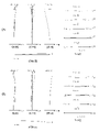
- FIG. 1 is a diagram showing a lens configuration of a variable power optical system according to a first example
- FIG. FIGS. 2A and 2B are diagrams of various aberrations in the wide-angle end state and the telephoto end state of the variable power optical system according to the first embodiment, respectively, when focusing on infinity.
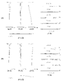
- FIG. 10 is a diagram showing a lens configuration of a variable-magnification optical system according to a second example
- 4A and 4B are diagrams of various aberrations in the wide-angle end state and the telephoto end state of the variable power optical system according to the second embodiment, respectively, when focusing on infinity.
- FIG. 11 is a diagram showing a lens configuration of a variable-magnification optical system according to a third example; 6A and 6B are diagrams of various aberrations in the wide-angle end state and the telephoto end state of the variable power optical system according to the third embodiment, respectively, when focusing on infinity.
- FIG. 11 is a diagram showing a lens configuration of a variable-magnification optical system according to a fourth example; 8A and 8B are diagrams of various aberrations in the wide-angle end state and the telephoto end state of the variable power optical system according to the fourth embodiment, respectively, when focusing on infinity. It is a figure which shows the structure of the camera provided with the variable-magnification optical system which concerns on each embodiment.
- 4 is a flow chart showing a method of manufacturing the variable magnification optical system according to the first embodiment; 9 is a flow chart showing a method of manufacturing a variable magnification optical system according to the second embodiment;
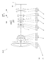
- the camera 1 comprises a main body 2 and a photographing lens 3 attached to the main body 2.
- the main body 2 includes an imaging device 4 , a main body control section (not shown) that controls the operation of the digital camera, and a liquid crystal screen 5 .
- the taking lens 3 includes a variable magnification optical system ZL consisting of a plurality of lens groups, and a lens position control mechanism (not shown) that controls the position of each lens group.
- the lens position control mechanism includes a sensor that detects the position of the lens group, a motor that moves the lens group back and forth along the optical axis, a control circuit that drives the motor, and the like.
- variable magnification optical system ZL of the photographing lens 3 The light from the subject is condensed by the variable magnification optical system ZL of the photographing lens 3 and reaches the image plane I of the imaging device 4 .
- the light from the subject reaching the image plane I is photoelectrically converted by the imaging device 4 and recorded as digital image data in a memory (not shown).
- the digital image data recorded in the memory can be displayed on the liquid crystal screen 5 according to the user's operation.
- This camera may be a mirrorless camera or a single-lens reflex type camera having a quick return mirror.
- the variable power optical system ZL shown in FIG. 9 schematically shows the variable power optical system provided in the taking lens 3, and the lens configuration of the variable power optical system ZL is not limited to this configuration. No.
- a variable power optical system ZL(1) which is an example of a variable power optical system (zoom lens) ZL according to the first embodiment, includes positive lenses arranged in order from the object side along an optical axis. a first lens group G1 having refractive power, a second lens group G2 having negative refractive power, a third lens group G3 having positive refractive power, and a fourth lens group G4 having negative refractive power; and a fifth lens group G5 having negative refractive power.
- the fourth lens group G4 is a focusing lens group GF that moves along the optical axis during focusing.
- variable power optical system ZL satisfies the following conditional expression (1). 0.11 ⁇ f4/f5 ⁇ 0.70 (1) where f4 is the focal length of the fourth lens group G4 f5 is the focal length of the fifth lens group G5
- variable-magnification optical system ZL may be the variable power optical system ZL(2) shown in FIG. 3 or the variable power optical system ZL(3) shown in FIG.
- Conditional expression (1) defines an appropriate relationship between the focal length of the fourth lens group G4 and the focal length of the fifth lens group G5.
- conditional expression (1) When the corresponding value of conditional expression (1) exceeds the upper limit, the focal length of the fourth lens group G4 becomes longer, and the movement amount of the fourth lens group G4, which is the focusing lens group, during focusing becomes larger. , it becomes difficult to suppress variations in spherical aberration, coma, and curvature of field during focusing. Further, since the focal length of the fifth lens group G5 is shortened, it becomes difficult to correct the curvature of field generated in the fifth lens group G5. By setting the upper limit of conditional expression (1) to 0.65, and further to 0.60, the effects of this embodiment can be made more reliable.
- conditional expression (1) When the corresponding value of conditional expression (1) is below the lower limit, the focal length of the fourth lens group G4 is shortened, thereby correcting spherical aberration, coma and field curvature occurring in the fourth lens group G4. becomes difficult. In addition, since the focal length of the fifth lens group G5 becomes longer, the correction effect of the curvature of field by the fifth lens group G5 becomes smaller, making it difficult to obtain good optical performance.
- the lower limit of conditional expression (1) By setting the lower limit of conditional expression (1) to 0.15, and further to 0.20, the effects of this embodiment can be made more reliable.
- variable power optical system ZL preferably satisfies the following conditional expression (2). 0.01 ⁇ (-f4)/f3 ⁇ 5.00 (2) where f3 is the focal length of the third lens group G3
- Conditional expression (2) defines an appropriate relationship between the focal length of the fourth lens group G4 and the focal length of the third lens group G3. By satisfying conditional expression (2), spherical aberration, coma, and curvature of field can be satisfactorily corrected.
- conditional expression (2) exceeds the upper limit, the focal length of the fourth lens group G4 becomes longer, and the amount of movement of the fourth lens group G4, which is the focusing lens group, during focusing becomes larger. , it becomes difficult to suppress variations in spherical aberration, coma, and curvature of field during focusing. Further, since the focal length of the third lens group G3 is shortened, it becomes difficult to correct spherical aberration and coma aberration occurring in the third lens group G3. This embodiment can effect can be made more reliable.
- conditional expression (2) When the corresponding value of conditional expression (2) is below the lower limit, the focal length of the fourth lens group G4 is shortened, thereby correcting spherical aberration, coma and field curvature occurring in the fourth lens group G4. becomes difficult.
- the focal length of the third lens group G3 increases, the amount of movement of the third lens group G3 during zooming increases, making it difficult to suppress fluctuations in spherical aberration and coma during zooming. Become.
- the lower limit of conditional expression (2) By setting the lower limit of conditional expression (2) to 0.05, 1.00, 1.25, and further to 1.50, the effect of this embodiment can be made more reliable.
- variable power optical system ZL preferably satisfies the following conditional expression (3). 0.01 ⁇ f3/(-f5) ⁇ 1.00 (3) where f3 is the focal length of the third lens group G3
- Conditional expression (3) defines an appropriate relationship between the focal length of the third lens group G3 and the focal length of the fifth lens group G5.
- conditional expression (3) exceeds the upper limit, the focal length of the third lens group G3 becomes longer, so that the amount of movement of the third lens group G3 during zooming increases, resulting in an increase in the amount of movement of the third lens group G3 during zooming. It becomes difficult to suppress variations in spherical aberration and coma. Further, since the focal length of the fifth lens group G5 is shortened, it becomes difficult to correct the curvature of field generated in the fifth lens group G5. By setting the upper limit of conditional expression (3) to 0.75, 0.50, 0.29, and further to 0.25, the effects of this embodiment can be made more reliable.
- conditional expression (3) When the corresponding value of conditional expression (3) is below the lower limit, the focal length of the third lens group G3 becomes short, making it difficult to correct spherical aberration and coma aberration occurring in the third lens group G3. . In addition, since the focal length of the fifth lens group G5 becomes longer, the correction effect of the curvature of field by the fifth lens group G5 becomes smaller, making it difficult to obtain good optical performance.
- the lower limit of conditional expression (3) to 0.05, and further to 0.09, the effect of this embodiment can be made more reliable.
- variable power optical system ZL preferably satisfies the following conditional expression (4). 0.01 ⁇ f3/(-f45t) ⁇ 2.00 (4) where f3 is the focal length of the third lens group G3 f45t is the combined focal length of the fourth lens group G4 and the fifth lens group G5 in the telephoto end state
- Conditional expression (4) defines an appropriate relationship between the focal length of the third lens group G3 and the combined focal length of the fourth lens group G4 and the fifth lens group G5 in the telephoto end state.
- conditional expression (4) exceeds the upper limit, the focal length of the third lens group G3 becomes longer, so that the amount of movement of the third lens group G3 during zooming increases, resulting in an increase in the amount of movement of the third lens group G3 during zooming. It becomes difficult to suppress variations in spherical aberration and coma.
- the combined focal length of the fourth lens group G4 and the fifth lens group G5 in the telephoto end state is shortened, spherical aberration, coma aberration, and curvature of field generated in the fourth lens group G4 and the fifth lens group G5 becomes difficult to correct.
- conditional expression (4) When the corresponding value of conditional expression (4) is below the lower limit, the focal length of the third lens group G3 becomes short, making it difficult to correct spherical aberration and coma aberration occurring in the third lens group G3. .
- the combined focal length of the fourth lens group G4 and the fifth lens group G5 in the telephoto end state becomes long, the amount of movement of the fourth lens group G4 and the fifth lens group G5 during zooming becomes large. It becomes difficult to suppress fluctuations in spherical aberration, coma, and curvature of field when magnifying.
- the lower limit of conditional expression (4) By setting the lower limit of conditional expression (4) to 0.10, 0.25, 0.33, 0.45, and further to 0.56, the effects of this embodiment can be made more reliable. .
- variable power optical system ZL preferably satisfies the following conditional expression (5). 0.01 ⁇ 5t/ ⁇ 5w ⁇ 2.00 (5) where ⁇ 5t: lateral magnification of the fifth lens group G5 in the telephoto end state ⁇ 5w: lateral magnification of the fifth lens group G5 in the wide-angle end state
- Conditional expression (5) defines an appropriate relationship between the lateral magnification of the fifth lens group G5 in the telephoto end state and the lateral magnification of the fifth lens group G5 in the wide-angle end state. Satisfying the conditional expression (5) is preferable because it is possible to obtain a variable power optical system having good optical performance while realizing reduction in size and weight.
- the upper limit of conditional expression (5) to 1.80, 1.65, 1.55, 1.49, and further to 1.30, the effects of this embodiment can be made more reliable.
- the lower limit of conditional expression (5) By setting the lower limit of conditional expression (5) to 0.10, 0.25, 0.50, 0.75, 0.90, and further to 1.07, the effects of the present embodiment can be made more reliable. can do.
- variable power optical system ZL preferably satisfies the following conditional expression (6). 0.01 ⁇ Bfw/fw ⁇ 0.95 (6)
- Bfw back focus of the variable-magnification optical system ZL in the wide-angle end state
- fw focal length of the variable-magnification optical system ZL in the wide-angle end state
- Conditional expression (6) defines an appropriate relationship between the back focus of the variable power optical system ZL in the wide-angle end state and the focal length of the variable power optical system ZL in the wide-angle end state.
- the back focus of the variable power optical system ZL is the air-equivalent distance on the optical axis from the lens surface closest to the image plane side to the image plane I of the variable power optical system ZL.
- Satisfying the conditional expression (6) is preferable because it is possible to obtain a variable magnification optical system having good optical performance while achieving a reduction in size and weight.
- variable power optical system ZL it is desirable that the fifth lens group G5 consist of two lenses. Thereby, it is possible to satisfactorily suppress fluctuations in curvature of field during zooming.
- the third lens group G3 has a lens that satisfies the following conditional expression (7). 75.00 ⁇ 3L (7) where ⁇ 3L: the Abbe number of the lens in the third lens group G3
- Conditional expression (7) defines an appropriate range for the Abbe numbers of the lenses in the third lens group G3. If the third lens group G3 has a lens that satisfies the conditional expression (7), it is preferable because a variable magnification optical system having good optical performance with corrected chromatic aberration can be obtained. By setting the lower limit of conditional expression (7) to 77.00, 80.00, and further to 82.00, the effect of this embodiment can be made more reliable.
- the third lens group G3 has a vibration reduction group GVR that is movable so as to have a displacement component in the direction perpendicular to the optical axis. It is desirable to have As a result, it is possible to obtain a variable-magnification optical system that achieves a reduction in size and weight and that has excellent anti-vibration performance, which is preferable.
- variable power optical system ZL preferably satisfies the following conditional expression (8). 0.01 ⁇ f3/fVR ⁇ 2.00 (8) where f3: focal length of the third lens group G3 fVR: focal length of the anti-vibration group GVR
- Conditional expression (8) defines an appropriate relationship between the focal length of the third lens group G3 and the focal length of the anti-vibration group GVR. Satisfying conditional expression (8) makes it possible to suppress eccentric coma and asymmetric curvature of field when correcting image blur, and to obtain good vibration reduction performance.
- conditional expression (8) When the corresponding value of conditional expression (8) exceeds the upper limit value, the focal length of the anti-vibration group GVR is shortened. Curvature is difficult to suppress.
- the upper limit of conditional expression (8) By setting the upper limit of conditional expression (8) to 1.75, 1.50, 1.25, and further to 1.00, the effect of this embodiment can be made more reliable.
- conditional expression (8) When the corresponding value of conditional expression (8) is below the lower limit, the focal length of the anti-vibration group GVR becomes longer, so that the amount of movement of the anti-vibration group GVR when correcting image blur increases, causing eccentric coma, It becomes difficult to suppress asymmetric curvature of field.
- the lower limit of conditional expression (8) By setting the lower limit of conditional expression (8) to 0.10, 0.30, 0.40, and further to 0.45, the effect of this embodiment can be made more reliable.
- variable magnification optical system ZL it is desirable that the anti-vibration group GVR is arranged closest to the image plane side of the third lens group G3. As a result, it is possible to obtain a good anti-vibration performance while maintaining the optical performance of the variable magnification optical system.
- a variable power optical system ZL(1) as an example of the variable power optical system (zoom lens) ZL according to the second embodiment includes positive lenses arranged in order from the object side along the optical axis.
- It consists of a focusing lens group GF and a rear group GR having at least one lens group.
- the focusing lens group GF moves along the optical axis during focusing.
- variable-magnification optical system ZL satisfies the following conditional expression (9) and the above-described conditional expression (6). 0.30 ⁇ (-f2)/fMt ⁇ 0.80 (9) 0.01 ⁇ Bfw/fw ⁇ 0.95 (6)
- f2 focal length of second lens group
- G2 fMt: focal length of intermediate group GM in telephoto end state
- Bfw back focus of variable power optical system ZL in wide-angle end state
- fw focal length of variable power optical system ZL in wide-angle end state
- variable-magnification optical system ZL may be the variable power optical system ZL(2) shown in FIG. 3, the variable power optical system ZL(3) shown in FIG. 5, or the variable power optical system ZL(3) shown in FIG. System ZL(4) may also be used.
- Conditional expression (9) defines an appropriate relationship between the focal length of the second lens group G2 and the focal length of the intermediate group GM in the telephoto end state.
- conditional expression (9) exceeds the upper limit value, the focal length of the second lens group G2 increases, so that the amount of movement of the second lens group G2 during zooming increases, resulting in a large amount of movement during zooming. It becomes difficult to suppress variations in spherical aberration, coma, and curvature of field. In addition, since the focal length of the middle group GM in the telephoto end state becomes short, it becomes difficult to correct spherical aberration and coma generated in the middle group GM. By setting the upper limit of conditional expression (9) to 0.75, and further to 0.70, the effects of this embodiment can be made more reliable.
- conditional expression (9) When the corresponding value of conditional expression (9) is below the lower limit, the focal length of the second lens group G2 is shortened, thereby correcting spherical aberration, coma aberration, and curvature of field generated in the second lens group G2. becomes difficult.
- the longer the focal length of the middle group GM in the telephoto end state the greater the amount of movement of the middle group GM during zooming, making it difficult to suppress fluctuations in spherical aberration and coma during zooming. Become.
- the lower limit of conditional expression (9) By setting the lower limit of conditional expression (9) to 0.40, and further to 0.50, the effects of this embodiment can be made more reliable.
- conditional expression (6) defines an appropriate relationship between the back focus of the variable power optical system ZL in the wide-angle end state and the focal length of the variable power optical system ZL in the wide-angle end state. Satisfying the conditional expression (6) is preferable because it is possible to obtain a variable magnification optical system having good optical performance while achieving a reduction in size and weight.
- the upper limit of conditional expression (6) 0.90, 0.85, 0.80, 0.78, 0.75, 0.65, and further to 0.58, the effect of this embodiment can be further enhanced. can be made certain.
- the lower limit of conditional expression (6) By setting the lower limit of conditional expression (6) to 0.10, 0.30, 0.40, and further 0.50, the effect of this embodiment can be made more reliable.
- variable power optical system ZL preferably satisfies the following conditional expression (10). 0.01 ⁇ (-fF)/fMt ⁇ 5.00 (10) where fF is the focal length of the focusing lens group GF
- Conditional expression (10) defines an appropriate relationship between the focal length of the focusing lens group GF and the focal length of the intermediate group GM in the telephoto end state. By satisfying conditional expression (10), spherical aberration, coma, and curvature of field can be satisfactorily corrected.
- conditional expression (10) exceeds the upper limit value, the focal length of the focusing lens group GF becomes long, so that the amount of movement of the focusing lens group GF during focusing becomes large. It becomes difficult to suppress variations in spherical aberration, coma, and curvature of field. In addition, since the focal length of the middle group GM in the telephoto end state becomes short, it becomes difficult to correct spherical aberration and coma generated in the middle group GM.
- the upper limit of conditional expression (10) By setting the upper limit of conditional expression (10) to 4.50, 4.00, 3.50, 3.00, and further to 2.30, the effects of this embodiment can be made more reliable. .
- conditional expression (10) When the corresponding value of conditional expression (10) is below the lower limit, the focal length of the focusing lens group GF becomes short, thereby correcting spherical aberration, coma aberration, and curvature of field generated in the focusing lens group GF. becomes difficult.
- the longer the focal length of the middle group GM in the telephoto end state the greater the amount of movement of the middle group GM during zooming, making it difficult to suppress fluctuations in spherical aberration and coma during zooming. Become.
- the lower limit of conditional expression (10) By setting the lower limit of conditional expression (10) to 0.10, 0.50, 0.70, 1.00, 1.25, and further to 1.50, the effects of the present embodiment can be made more reliable. can do.
- variable power optical system ZL preferably satisfies the following conditional expression (11). 0.01 ⁇ fMt/
- Conditional expression (11) defines an appropriate relationship between the focal length of the middle group GM in the telephoto end state and the focal length of the rear group GR in the telephoto end state.
- conditional expression (11) exceeds the upper limit value, the focal length of the middle group GM in the telephoto end state becomes longer, so that the amount of movement of the middle group GM during zooming increases, resulting in an increase in the amount of movement of the middle group GM during zooming. It becomes difficult to suppress variations in spherical aberration and coma. Further, since the focal length of the rear group GR becomes short in the telephoto end state, it becomes difficult to correct the curvature of field generated in the rear group GR. By setting the upper limit of conditional expression (11) to 0.85, 0.70, 0.60, 0.50, 0.35, and further to 0.25, the effects of the present embodiment are more reliable. can do.
- conditional expression (11) If the corresponding value of conditional expression (11) is below the lower limit, the focal length of the middle group GM in the telephoto end state becomes short, making it difficult to correct spherical aberration and coma generated in the middle group GM. . In addition, since the focal length of the rear group GR becomes long in the telephoto end state, the correction effect of the field curvature by the rear group GR becomes small, making it difficult to obtain good optical performance. By setting the lower limit of conditional expression (11) to 0.03, and further to 0.04, the effects of this embodiment can be made more reliable.
- variable power optical system ZL preferably satisfies the following conditional expression (12). 0.01 ⁇ (-fF)/
- Conditional expression (12) defines an appropriate relationship between the focal length of the focusing lens group GF and the focal length of the rear group GR in the telephoto end state.
- conditional expression (12) exceeds the upper limit value, the focal length of the focusing lens group GF becomes longer, and the amount of movement of the focusing lens group GF at the time of focusing becomes larger. It becomes difficult to suppress variations in spherical aberration, coma, and curvature of field. Further, since the focal length of the rear group GR becomes short in the telephoto end state, it becomes difficult to correct the curvature of field generated in the rear group GR.
- the upper limit of conditional expression (12) By setting the upper limit of conditional expression (12) to 0.85, 0.75, 0.65, 0.60, and further to 0.55, the effects of this embodiment can be made more reliable. .
- conditional expression (12) When the corresponding value of conditional expression (12) is below the lower limit, the focal length of the focusing lens group GF becomes short, thereby correcting spherical aberration, coma aberration, and curvature of field generated in the focusing lens group GF. becomes difficult. In addition, since the focal length of the rear group GR becomes long in the telephoto end state, the correction effect of the field curvature by the rear group GR becomes small, making it difficult to obtain good optical performance. By setting the lower limit of conditional expression (12) to 0.06, and further to 0.075, the effect of this embodiment can be made more reliable.
- variable power optical system ZL preferably satisfies the following conditional expression (13). 0.01 ⁇ fMt/(-fFRt) ⁇ 1.00 (13) where fFRt is the combined focal length of at least one lens group of the focusing lens group GF and the rear group GR in the telephoto end state.
- Conditional expression (13) defines an appropriate relationship between the focal length of the intermediate group GM in the telephoto end state and the combined focal length of at least one lens group of the focusing lens group GF and the rear group GR in the telephoto end state. It is. By satisfying conditional expression (13), spherical aberration, coma, and curvature of field can be satisfactorily corrected.
- conditional expression (13) exceeds the upper limit value, the focal length of the middle group GM in the telephoto end state becomes long, so that the amount of movement of the middle group GM during zooming increases, resulting in an increase in the amount of movement of the middle group GM during zooming. It becomes difficult to suppress variations in spherical aberration and coma.
- the combined focal length of at least one of the focusing lens group GF and the rear group GR becomes short in the telephoto end state, spherical aberration occurs in the lens group arranged closer to the image plane than the intermediate group GM. , coma, and field curvature.
- conditional expression (13) If the corresponding value of conditional expression (13) is below the lower limit, the focal length of the intermediate group GM in the telephoto end state becomes short, making it difficult to correct spherical aberration and coma generated in the intermediate group GM. .
- the lens group arranged closer to the image plane than the intermediate group GM can The amount of movement increases, and it becomes difficult to suppress variations in spherical aberration, coma, and curvature of field during zooming.
- the lower limit of conditional expression (13) By setting the lower limit of conditional expression (13) to 0.10, 0.25, 0.35, and further to 0.45, the effect of this embodiment can be made more reliable.
- variable power optical system ZL preferably satisfies the following conditional expression (14). 0.10 ⁇ Rt/ ⁇ Rw ⁇ 2.00 (14) where ⁇ Rt: lateral magnification of the rear group GR in the telephoto end state ⁇ Rw: lateral magnification of the rear group GR in the wide-angle end state
- Conditional expression (14) defines an appropriate relationship between the lateral magnification of the rear group GR in the telephoto end state and the lateral magnification of the rear group GR in the wide-angle end state. Satisfying the conditional expression (14) is preferable because it is possible to obtain a variable power optical system having good optical performance while achieving a reduction in size and weight.
- the upper limit of conditional expression (14) to 1.80, 1.65, 1.50, 1.45, 1.35, and further to 1.25, the effects of the present embodiment are more reliable. can do.
- the lower limit of conditional expression (14) to 0.10, 0.25, 0.40, 0.50, and further to 0.70, the effects of this embodiment can be made more reliable. .
- variable power optical system ZL it is desirable that the rear group GR consist of two lenses. Thereby, it is possible to satisfactorily suppress fluctuations in curvature of field during zooming.
- variable power optical system ZL it is desirable that the intermediate group GM consist of one lens group. This is preferable because it is possible to obtain a variable magnification optical system having good optical performance while realizing a reduction in size and weight.
- variable power optical system ZL it is desirable that the rear group GR consist of one lens group. This is preferable because it is possible to obtain a variable magnification optical system having good optical performance while realizing a reduction in size and weight.
- variable magnification optical system ZL it is desirable that the rear group GR have negative refractive power. This is preferable because it is possible to obtain a variable magnification optical system having good optical performance while realizing a reduction in size and weight.
- the intermediate group GM has a lens that satisfies the following conditional expression (15). 75.00 ⁇ ML (15) where ⁇ ML: the Abbe number of the lens in the middle group GM
- Conditional expression (15) defines an appropriate range for the Abbe number of the lens in the intermediate group GM. If the middle group GM has a lens that satisfies the conditional expression (15), it is preferable because a variable magnification optical system having good optical performance in which chromatic aberration is corrected can be obtained. By setting the lower limit of conditional expression (15) to 76.00, 77.50, 78.50, and further to 80.00, the effect of this embodiment can be made more reliable.
- variable-magnification optical system ZL it is desirable that the intermediate group GM has, as a part of the intermediate group GM, a vibration reduction group GVR that can move so as to have a displacement component in the direction perpendicular to the optical axis. .
- a vibration reduction group GVR that can move so as to have a displacement component in the direction perpendicular to the optical axis.
- variable power optical system ZL preferably satisfies the following conditional expression (16). 0.01 ⁇ fMt/fVR ⁇ 1.00 (16) where fVR is the focal length of the anti-vibration group GVR
- Conditional expression (16) defines an appropriate relationship between the focal length of the middle group GM and the focal length of the anti-vibration group GVR in the telephoto end state. Satisfying conditional expression (16) makes it possible to suppress eccentric coma and asymmetric curvature of field when correcting image blur, and to obtain good image stabilization performance.
- conditional expression (16) exceeds the upper limit value, the focal length of the anti-vibration group GVR is shortened. Curvature is difficult to suppress.
- conditional expression (16) When the corresponding value of conditional expression (16) is below the lower limit, the focal length of the anti-vibration group GVR becomes longer, so that the amount of movement of the anti-vibration group GVR when correcting image blur increases. It becomes difficult to suppress asymmetric curvature of field.
- the lower limit of conditional expression (16) By setting the lower limit of conditional expression (16) to 0.10, 0.25, 0.45, and further to 0.60, the effect of this embodiment can be made more reliable.
- variable magnification optical system ZL it is desirable that the vibration reduction group GVR is arranged closest to the image plane side of the intermediate group GM. As a result, it is possible to obtain a good anti-vibration performance while maintaining the optical performance of the variable magnification optical system.
- variable magnification optical system ZL according to the first embodiment and the second embodiment satisfy the following conditional expression (17). 0.01 ⁇ fVR/(-fF) ⁇ 2.50 (17) where fVR: focal length of anti-vibration group GVR fF: focal length of focusing lens group GF
- Conditional expression (17) defines an appropriate relationship between the focal length of the anti-vibration group GVR and the focal length of the focusing lens group GF. Satisfying conditional expression (17) makes it possible to suppress eccentric coma aberration and asymmetric curvature of field when correcting image blur, and to obtain excellent image stabilization performance.
- conditional expression (17) exceeds the upper limit value, the focal length of the anti-vibration group GVR becomes long, and the amount of movement of the anti-vibration group GVR when correcting image blur increases, resulting in eccentric coma aberration, It becomes difficult to suppress asymmetric curvature of field.
- the focal length of the focusing lens group GF is shortened, it becomes difficult to correct spherical aberration, coma aberration, and curvature of field generated in the focusing lens group GF.
- conditional expression (17) When the corresponding value of conditional expression (17) is below the lower limit, the focal length of the anti-vibration group GVR is shortened, and decentration coma generated in the anti-vibration group GVR when correcting image blur and an asymmetric image plane Curvature is difficult to suppress. In addition, by increasing the focal length of the focusing lens group GF, the amount of movement of the focusing lens group GF during focusing becomes large, suppressing variations in spherical aberration, coma, and field curvature during focusing. becomes difficult. By setting the lower limit of conditional expression (17) to 0.10, 0.40, 0.63, 0.70, and further to 1.00, the effect of each embodiment can be made more reliable. .
- the anti-vibration group GVR preferably consists of two lenses. This makes it possible to suppress variations in chromatic aberration when image blur is corrected.
- variable power optical system ZL preferably satisfies the following conditional expression (18). 0.01 ⁇ (-f2)/f1 ⁇ 1.00 (18) where f1: focal length of the first lens group G1 f2: focal length of the second lens group G2
- Conditional expression (18) defines an appropriate relationship between the focal length of the second lens group G2 and the focal length of the first lens group G1.
- conditional expression (18) exceeds the upper limit value, the focal length of the second lens group G2 becomes longer, so that the amount of movement of the second lens group G2 during zooming increases. It becomes difficult to suppress variations in spherical aberration, coma, and curvature of field. Further, since the focal length of the first lens group G1 is shortened, it becomes difficult to correct spherical aberration, coma aberration, and curvature of field generated in the first lens group G1.
- the upper limit of conditional expression (18) By setting the upper limit of conditional expression (18) to 0.75, 0.50, 0.30, 0.25, 0.20, and further to 0.18, the effect of each embodiment can be more assured. can do.
- conditional expression (18) When the corresponding value of conditional expression (18) is below the lower limit, the focal length of the second lens group G2 is shortened, thereby correcting spherical aberration, coma and field curvature occurring in the second lens group G2. becomes difficult. In addition, since the focal length of the first lens group G1 increases, the amount of movement of the first lens group G1 during zooming increases, suppressing variations in spherical aberration, coma, and curvature of field during zooming. becomes difficult. By setting the lower limit of conditional expression (18) to 0.05, 0.10, and further 0.16, the effect of each embodiment can be made more reliable.
- variable power optical system ZL preferably satisfies the following conditional expression (19). 0.01 ⁇ TLt/ft ⁇ 2.00 (19) where TLt is the total length of the variable magnification optical system ZL in the telephoto end state ft is the focal length of the variable magnification optical system ZL in the telephoto end state
- Conditional expression (19) defines an appropriate relationship between the total length of the variable power optical system ZL in the telephoto end state and the focal length of the variable power optical system ZL in the telephoto end state.
- the total length of the variable-magnification optical system ZL is the distance on the optical axis from the lens surface closest to the object side of the variable-magnification optical system ZL to the image plane I
- variable power optical system ZL preferably satisfies the following conditional expression (20). 0.01 ⁇ Ft/ ⁇ Fw ⁇ 2.00 (20) where ⁇ Ft: lateral magnification of the focusing lens group GF in the telephoto end state ⁇ Fw: lateral magnification of the focusing lens group GF in the wide-angle end state
- Conditional expression (20) defines an appropriate relationship between the lateral magnification of the focusing lens group GF in the telephoto end state and the lateral magnification of the focusing lens group GF in the wide-angle end state. Satisfying the conditional expression (20) is preferable because it is possible to obtain a variable-power optical system that is compact and lightweight and has good optical performance.
- the upper limit of conditional expression (20) to 1.80, 1.65, 1.50, and further to 1.35, the effect of each embodiment can be made more reliable.
- the lower limit of conditional expression (20) to 0.10, 0.50, 0.85, 0.90, 1.20, and further to 1.21, the effect of each embodiment can be more assured. can do.
- variable magnification optical system ZL it is desirable that the focusing lens group GF consist of two lenses. This makes it possible to suppress variations in chromatic aberration during focusing.
- the first lens group G1 has a lens that satisfies the following conditional expression (21). 75.00 ⁇ 1L (21) where ⁇ 1L: the Abbe number of the lens in the first lens group G1
- Conditional expression (21) defines an appropriate range for the Abbe numbers of the lenses in the first lens group G1. If the first lens group G1 has a lens that satisfies the conditional expression (21), it is preferable because a variable magnification optical system having good optical performance with corrected chromatic aberration can be obtained. By setting the lower limit of conditional expression (21) to 76.00, 77.50, 78.50, and further to 80.00, the effect of this embodiment can be made more reliable.
- a method for manufacturing the variable power optical system ZL according to the first embodiment will be outlined with reference to FIG.
- a fourth lens group G4 having negative refractive power and a fifth lens group G5 having negative refractive power are arranged (step ST1).
- the fourth lens group G4 is configured to be a focusing lens group that moves along the optical axis during focusing (step ST3).
- each lens is arranged in the lens barrel so as to satisfy at least the conditional expression (1) (step ST4). According to such a manufacturing method, it is possible to manufacture a variable power optical system having good optical performance while achieving a reduction in size and weight.
- a method for manufacturing the variable power optical system ZL according to the second embodiment will be outlined with reference to FIG.
- a middle group GM having power, a focusing lens group GF having negative refractive power, and a rear group GR having at least one lens group are arranged (step ST11).
- it is configured so that the distance between adjacent lens groups changes during zooming (step ST12).
- the focusing lens group GF is configured to move along the optical axis during focusing (step ST13).
- each lens is arranged in the lens barrel so as to satisfy at least the conditional expressions (9) and (6) (step ST14). According to such a manufacturing method, it is possible to manufacture a variable power optical system having good optical performance while achieving a reduction in size and weight.
- variable-magnification optical system ZL according to the example of each embodiment will be described based on the drawings.
- 1, 3, 5, and 7 are cross-sectional views showing configurations and refractive power distributions of variable magnification optical systems ZL ⁇ ZL(1) to ZL(4) ⁇ according to first to fourth examples.
- Examples corresponding to the first embodiment are the first to third examples
- examples corresponding to the second embodiment are the first to fourth examples.
- the moving direction of the focusing lens group when focusing on a short distance object from infinity is indicated by an arrow together with the word "focus”.
- the moving direction of the anti-vibration group when correcting image blur is indicated by an arrow together with the word "vibration isolation”.
- each lens group is represented by a combination of symbol G and a number, and each lens is represented by a combination of symbol L and a number.
- the lens groups and the like are represented independently using combinations of symbols and numerals for each embodiment. Therefore, even if the same reference numerals and symbols are used between the embodiments, it does not mean that they have the same configuration.
- f is the focal length of the entire lens system
- FNO is the F number
- ⁇ is the half angle of view (unit is ° (degrees))
- Y is the image height.
- TL indicates the distance obtained by adding Bf (back focus) to the distance on the optical axis from the lens surface closest to the object side to the lens surface closest to the image plane in the variable power optical system when focusing on infinity, where Bf is infinity. It shows the distance (air conversion distance) on the optical axis from the lens surface closest to the image plane to the image plane in the variable-magnification optical system when focusing at a far distance.
- fM indicates the focal length of the middle group
- fR indicates the focal length of the rear group. Note that these values are shown for each of the zooming states of the wide-angle end (W) and the telephoto end (T).
- fF indicates the focal length of the focusing lens group.
- fVR indicates the focal length of the anti-vibration group.
- fFRt represents the combined focal length of at least one of the in-focus lens group and the rear group in the telephoto end state.
- f45t represents the combined focal length of the fourth lens group and the fifth lens group in the telephoto end state.
- ⁇ Fw represents the lateral magnification of the focusing lens group in the wide-angle end state.
- ⁇ Ft indicates the lateral magnification of the focusing lens group in the telephoto end state.
- ⁇ Rw indicates the lateral magnification of the rear group in the wide-angle end state.
- ⁇ Rt indicates the lateral magnification of the rear group in the telephoto end state.
- ⁇ 4w indicates the lateral magnification of the fourth lens group in the wide-angle end state.
- ⁇ 4t indicates the lateral magnification of the fourth lens group in the telephoto end state.
- ⁇ 5w indicates the lateral magnification of the fifth lens group in the wide-angle end state.
- ⁇ 5t indicates the lateral magnification of the fifth lens group in the telephoto end state.
- the surface number indicates the order of the optical surfaces from the object side along the direction in which light rays travel
- R is the radius of curvature of each optical surface (the surface whose center of curvature is located on the image side). is a positive value)
- D is the distance on the optical axis from each optical surface to the next optical surface (or image plane)
- nd is the refractive index for the d-line of the material of the optical member
- ⁇ d is the optical
- the Abbe numbers of the materials of the members are shown with reference to the d-line.
- the radius of curvature “ ⁇ ” indicates a plane or an aperture
- (diaphragm S) indicates an aperture diaphragm S, respectively.
- the [Variable Spacing Data] table shows the surface spacing at surface number i for which the surface spacing is (Di) in the [Lens Specifications] table.
- the [Variable Spacing Data] table shows the surface spacing in the infinity focused state and the surface spacing in the close distance focused state.
- the [Lens group data] table shows the starting surface (surface closest to the object side) and focal length of each lens group.
- mm is generally used for the focal length f, radius of curvature R, surface spacing D, and other lengths in all specifications below, but the optical system is proportionally enlarged. Alternatively, it is not limited to this because equivalent optical performance can be obtained even if it is proportionally reduced.
- FIG. 1 is a diagram showing the lens configuration of a variable magnification optical system according to the first embodiment.
- the variable power optical system ZL(1) according to the first example includes a first lens group G1 having positive refractive power and a second lens group having negative refractive power, which are arranged in order from the object side along the optical axis. It consists of a group G2, a third lens group G3 having positive refractive power, a fourth lens group G4 having negative refractive power, and a fifth lens group G5 having negative refractive power.
- the first lens group G1 moves along the optical axis toward the object side
- the second lens group G2 moves along the optical axis once to the image plane.
- the third lens group G3, the fourth lens group G4, and the fifth lens group G5 move along the optical axis toward the object side, and the distance between the adjacent lens groups becomes Change.
- An aperture diaphragm S is arranged between the second lens group G2 and the third lens group G3, and during zooming, the aperture diaphragm S moves along the optical axis together with the third lens group G3.
- the sign (+) or (-) attached to each lens group symbol indicates the refractive power of each lens group, and this is the same for all the following examples.
- the first lens group G1 includes a cemented lens constructed by a negative meniscus lens L11 having a convex surface facing the object side and a biconvex positive lens L12 arranged in order from the object side along the optical axis, and a cemented lens having a convex surface facing the object side. and a positive meniscus lens L13.
- the second lens group G2 includes a negative meniscus lens L21 having a convex surface facing the object side, a biconcave negative lens L22, and a biconvex positive lens L23, which are arranged in order from the object side along the optical axis. and a negative meniscus lens L24 having a concave surface facing the object side.
- the third lens group G3 includes a biconvex positive lens L31, a biconvex positive lens L32, and a negative meniscus lens L33 having a convex surface facing the object side, which are arranged in order from the object side along the optical axis. It is composed of a cemented lens to which a convex positive lens L34 is cemented, and a cemented lens to which a biconvex positive lens L35 and a negative meniscus lens L36 having a concave surface facing the object side are cemented.
- the positive lens L31 is a hybrid lens formed by providing a resin layer on the object-side surface of a glass lens body.
- the object-side surface of the resin layer is aspherical, and the positive lens L31 is a compound aspherical lens.
- the surface number 15 is the object side surface of the resin layer
- the surface number 16 is the image side surface of the resin layer and the object side surface of the lens body (surface where both are joined)
- Numeral 17 indicates the image plane side surface of the lens body.
- the positive lens L35 is also a hybrid lens that is configured by providing a resin layer on the object-side surface of the glass lens body.
- the object-side surface of the resin layer is aspherical, and the positive lens L35 is also a compound aspherical lens.
- the surface number 23 is the object side surface of the resin layer
- the surface number 24 is the image side surface of the resin layer and the object side surface of the lens body (surface where both are joined)
- Numeral 25 indicates the image plane side surface of the lens body (the surface cemented with the negative meniscus lens L36).
- the fourth lens group G4 is composed of a cemented lens in which a biconvex positive lens L41 and a biconcave negative lens L42 are cemented in order from the object side.
- the fifth lens group G5 is composed of a negative meniscus lens L51 with a concave surface facing the object side and a positive meniscus lens L52 with a concave surface facing the object side, which are arranged in order from the object side along the optical axis.
- An image plane I is arranged on the image side of the fifth lens group G5.
- a parallel plate PP is arranged between the fifth lens group G5 and the image plane I.
- the third lens group G3 constitutes an intermediate group GM having positive refractive power as a whole.
- the positive lens L35 and the negative meniscus lens L36 arranged closest to the image plane in the third lens group G3 are movable so as to have a displacement component in the direction perpendicular to the optical axis. Construct the vibration group GVR.
- the fourth lens group G4 corresponds to the focusing lens group GF that moves along the optical axis during focusing. During focusing from an infinity object to a short distance object, the focusing lens group GF (the entirety of the fourth lens group G4) moves along the optical axis toward the image plane side.
- the fifth lens group G5 constitutes a rear group GR having negative refractive power as a whole.
- Table 1 below lists the values of the specifications of the variable power optical system according to the first example.
- FIG. 2(A) is a diagram of various aberrations when focusing on infinity in the wide-angle end state of the variable power optical system according to the first example.
- FIG. 2B is a diagram of various aberrations in the telephoto end state of the variable power optical system according to the first embodiment when focusing on infinity.
- FNO indicates F number
- Y indicates image height.
- the spherical aberration diagram shows the F-number value corresponding to the maximum aperture
- the astigmatism diagram and the distortion diagram show the maximum image height
- the coma aberration diagram shows the value of each image height.
- a solid line indicates a sagittal image plane, and a broken line indicates a meridional image plane.
- aberration diagrams of each example shown below the same reference numerals as in the present example are used, and redundant description is omitted.
- variable magnification optical system according to Example 1 has excellent imaging performance, with various aberrations well corrected from the wide-angle end state to the telephoto end state.
- FIG. 3 is a diagram showing the lens configuration of the variable magnification optical system according to the second embodiment.
- the variable magnification optical system ZL(2) according to the second embodiment includes a first lens group G1 having positive refractive power and a second lens group having negative refractive power, which are arranged in order from the object side along the optical axis. It consists of a group G2, a third lens group G3 having positive refractive power, a fourth lens group G4 having negative refractive power, and a fifth lens group G5 having negative refractive power.
- the first lens group G1 moves along the optical axis toward the object side
- the second lens group G2 moves along the optical axis once to the image plane.
- the third lens group G3, the fourth lens group G4, and the fifth lens group G5 move along the optical axis toward the object side, and the distance between the adjacent lens groups becomes Change.
- An aperture diaphragm S is arranged between the second lens group G2 and the third lens group G3, and during zooming, the aperture diaphragm S moves along the optical axis together with the third lens group G3.
- the first lens group G1, the second lens group G2, the fourth lens group G4, and the fifth lens group G5 are constructed in the same manner as in the first embodiment. , and the detailed description of each of these lenses is omitted.
- the third lens group G3 includes a biconvex positive lens L31, a positive meniscus lens L32 with a convex surface facing the object side, and a negative meniscus lens with a convex surface facing the object side, which are arranged in order from the object side along the optical axis.
- the positive lens L31 is a hybrid lens formed by providing a resin layer on the object-side surface of a glass lens body.
- the object-side surface of the resin layer is aspherical, and the positive lens L31 is a compound aspherical lens.
- the surface number 15 is the object side surface of the resin layer
- the surface number 16 is the image side surface of the resin layer and the object side surface of the lens body (surface where both are joined)
- Numeral 17 indicates the image plane side surface of the lens body.
- the positive lens L35 is also a hybrid lens that is configured by providing a resin layer on the object-side surface of the glass lens body.
- the object-side surface of the resin layer is aspherical, and the positive lens L35 is also a compound aspherical lens.
- the surface number 23 is the object side surface of the resin layer
- the surface number 24 is the image side surface of the resin layer and the object side surface of the lens body (surface where both are joined)
- Numeral 25 indicates the image plane side surface of the lens body (the surface cemented with the negative meniscus lens L36).
- the third lens group G3 constitutes an intermediate group GM having positive refractive power as a whole.
- the positive lens L35 and the negative meniscus lens L36 arranged closest to the image plane in the third lens group G3 are movable so as to have a displacement component in the direction perpendicular to the optical axis. Construct the vibration group GVR.
- the fourth lens group G4 corresponds to the focusing lens group GF that moves along the optical axis during focusing. During focusing from an infinity object to a short distance object, the focusing lens group GF (the entirety of the fourth lens group G4) moves along the optical axis toward the image plane side.
- the fifth lens group G5 constitutes a rear group GR having negative refractive power as a whole.
- Table 2 below lists the values of the specifications of the variable power optical system according to the second example.
- FIG. 4(A) is a diagram of various aberrations when focusing on infinity in the wide-angle end state of the variable power optical system according to the second embodiment.
- FIG. 4B is a diagram of various aberrations in the telephoto end state of the variable power optical system according to the second embodiment when focusing on infinity. From the various aberration diagrams, it can be seen that the variable power optical system according to the second example has various aberrations well corrected from the wide-angle end state to the telephoto end state, and has excellent imaging performance.
- FIG. 5 is a diagram showing the lens configuration of the variable magnification optical system according to the third embodiment.
- a variable magnification optical system ZL(3) according to the third embodiment includes a first lens group G1 having positive refractive power and a second lens group having negative refractive power, which are arranged in order from the object side along the optical axis. It consists of a group G2, a third lens group G3 having positive refractive power, a fourth lens group G4 having negative refractive power, and a fifth lens group G5 having negative refractive power.
- the first lens group G1, the second lens group G2, the third lens group G3, the fourth lens group G4, and the fifth lens group G5 Moving along the optical axis toward the object side, the distance between adjacent lens groups changes.
- An aperture diaphragm S is arranged between the second lens group G2 and the third lens group G3, and during zooming, the aperture diaphragm S moves along the optical axis together with the third lens group G3.
- the first lens group G1, the second lens group G2, and the fourth lens group G4 are constructed in the same manner as in the first embodiment, and are assigned the same reference numerals as in the first embodiment. Therefore, detailed description of each of these lenses will be omitted.
- the third lens group G3 is a cemented lens in which a biconvex positive lens L31 and a biconvex positive lens L32 and a biconcave negative lens L33 are joined in order from the object side along the optical axis. and a cemented lens in which a biconvex positive lens L34 and a negative meniscus lens L36 having a concave surface facing the object side are cemented together.
- the positive lens L31 is a hybrid lens formed by providing a resin layer on the object-side surface of a glass lens body. The object-side surface of the resin layer is aspherical, and the positive lens L31 is a compound aspherical lens.
- the surface number 15 is the object side surface of the resin layer
- the surface number 16 is the image side surface of the resin layer and the object side surface of the lens body (surface where both are joined)
- Numeral 17 indicates the image plane side surface of the lens body.
- the positive lens L35 is also a hybrid lens that is configured by providing a resin layer on the object-side surface of the glass lens body.
- the object-side surface of the resin layer is aspherical
- the positive lens L35 is also a compound aspherical lens.
- the surface number 23 is the object side surface of the resin layer
- the surface number 24 is the image side surface of the resin layer and the object side surface of the lens body (surface where both are joined)
- Numeral 25 indicates the image plane side surface of the lens body (the surface cemented with the negative meniscus lens L36).
- the fifth lens group G5 is composed of a negative meniscus lens L51 having a concave surface facing the object side and a biconvex positive lens L52 arranged in order from the object side along the optical axis.
- An image plane I is arranged on the image side of the fifth lens group G5.
- a parallel plate PP is arranged between the fifth lens group G5 and the image plane I.
- the third lens group G3 constitutes an intermediate group GM having positive refractive power as a whole.
- the positive lens L35 and the negative meniscus lens L36 arranged closest to the image plane in the third lens group G3 are movable so as to have a displacement component in the direction perpendicular to the optical axis. Construct the vibration group GVR.
- the fourth lens group G4 corresponds to the focusing lens group GF that moves along the optical axis during focusing. During focusing from an infinity object to a short distance object, the focusing lens group GF (the entirety of the fourth lens group G4) moves along the optical axis toward the image plane side.
- the fifth lens group G5 constitutes a rear group GR having negative refractive power as a whole.
- Table 3 lists the values of the specifications of the variable power optical system according to the third example.
- FIG. 6(A) is a diagram of various aberrations in the wide-angle end state of the variable power optical system according to the third embodiment when focusing on infinity.
- FIG. 6B is a diagram of various aberrations in the telephoto end state of the variable power optical system according to the third embodiment when focusing at infinity. From the various aberration diagrams, it can be seen that the variable magnification optical system according to the third example has various aberrations well corrected from the wide-angle end state to the telephoto end state, and has excellent imaging performance.
- FIG. 7 is a diagram showing the lens configuration of a variable-magnification optical system according to the fourth embodiment.
- a variable magnification optical system ZL(4) according to the fourth embodiment includes a first lens group G1 having positive refractive power and a second lens group having negative refractive power, which are arranged in order from the object side along the optical axis. a third lens group G3 having positive refractive power; a fourth lens group G4 having positive refractive power; a fifth lens group G5 having negative refractive power; It is composed of six lens groups G6.
- the first lens group G1, the second lens group G2, the third lens group G3, the fourth lens group G4, the fifth lens group G5, and The sixth lens group G6 moves along the optical axis toward the object side, and the distance between adjacent lens groups changes.
- An aperture diaphragm S is arranged between the second lens group G2 and the third lens group G3, and during zooming, the aperture diaphragm S moves along the optical axis together with the third lens group G3.
- the first lens group G1 is a cemented lens of a negative meniscus lens L11 having a convex surface facing the object side and a positive meniscus lens L12 having a convex surface facing the object side, arranged in order from the object side along the optical axis. and a positive meniscus lens L13 with a convex surface directed toward the .
- the second lens group G2 includes a negative meniscus lens L21 having a convex surface facing the object side, a biconcave negative lens L22, and a biconvex positive lens L23, which are arranged in order from the object side along the optical axis. and a biconcave negative lens L24.
- the third lens group G3 includes a biconvex positive lens L31, a positive meniscus lens L32 with a convex surface facing the object side, and a biconcave negative lens L33, which are arranged in order from the object side along the optical axis. consists of
- the fourth lens group G4 includes a biconvex positive lens L41 arranged in order from the object side along the optical axis, a negative meniscus lens L42 having a convex surface facing the object side, and a biconvex positive lens L43 cemented together. and a cemented lens.
- the positive lens L41 is a hybrid lens formed by providing a resin layer on the object-side surface of a glass lens body. The object-side surface of the resin layer is aspherical, and the positive lens L41 is a compound aspherical lens.
- the surface number 21 is the object side surface of the resin layer
- the surface number 22 is the image side surface of the resin layer and the object side surface of the lens body (surface where both are joined).
- Numeral 23 indicates the image plane side surface of the lens body.
- the fifth lens group G5 is composed of a cemented lens in which a biconvex positive lens L51 and a biconcave negative lens L52 are cemented in order from the object side.
- the sixth lens group G6 is composed of a negative meniscus lens L61 having a concave surface facing the object side and a biconvex positive lens L62 arranged in order from the object side along the optical axis.
- An image plane I is arranged on the image side of the sixth lens group G6.
- a parallel plate PP is arranged between the sixth lens group G6 and the image plane I.
- the third lens group G3 and the fourth lens group G4 constitute an intermediate group GM having positive refractive power as a whole.
- the positive lens L41 of the fourth lens group G4 constitutes a vibration reduction group GVR that is movable so as to have a displacement component in the direction perpendicular to the optical axis.
- the fifth lens group G5 corresponds to the focusing lens group GF that moves along the optical axis during focusing. During focusing from an infinity object to a close object, the focusing lens group GF (the entirety of the fifth lens group G5) moves along the optical axis toward the image plane side.
- the sixth lens group G6 constitutes a rear group GR having positive refractive power as a whole.
- Table 4 lists the values of the specifications of the variable power optical system according to the fourth example.
- FIG. 8(A) is a diagram of various aberrations when focusing on infinity in the wide-angle end state of the variable power optical system according to the fourth example.
- FIG. 8B is a diagram of various aberrations in the telephoto end state of the variable power optical system according to the fourth example when focusing on infinity. From the various aberration diagrams, it can be seen that the variable magnification optical system according to the fourth example has various aberrations well corrected from the wide-angle end state to the telephoto end state, and has excellent imaging performance.
- Conditional expression (1) 0.11 ⁇ f4/f5 ⁇ 0.70
- Conditional expression (2) 0.01 ⁇ (-f4)/f3 ⁇ 5.00
- Conditional expression (3) 0.01 ⁇ f3/(-f5) ⁇ 1.00
- Conditional expression (4) 0.01 ⁇ f3/(-f45t) ⁇ 2.00
- Conditional expression (5) 0.01 ⁇ 5t/ ⁇ 5w ⁇ 2.00
- Conditional expression (6) 0.01 ⁇ Bfw/fw ⁇ 0.95
- Conditional expression (7) 75.00 ⁇ 3L
- Conditional expression (8) 0.01 ⁇ f3/fVR ⁇ 2.00
- Conditional expression (9) 0.30 ⁇ (-f2)/fMt ⁇ 0.80
- Conditional expression (10) 0.01 ⁇ (-fF)/fMt ⁇ 5.00
- Conditional expression (11) 0.01 ⁇ fMt/
- Conditional expression (12) 0.01 ⁇ (-fF)/
- Conditional expression (11) 0.01 ⁇ fMt/
- variable magnification optical system of each embodiment has been shown with a 5-group configuration and a 6-group configuration, the present application is not limited to this, and other group configurations (for example, 7-group, 8-group, 9-group etc.) can also be configured.
- group configurations for example, 7-group, 8-group, 9-group etc.
- the intermediate group may be composed of three or more lens groups, and the rear group may be composed of two or more lens groups.
- the lens group refers to a portion having at least one lens separated by an air gap that changes during zooming.
- variable power optical system of each embodiment not only the fourth lens group or the fifth lens group, but also a single lens group, a plurality of lens groups, or a partial lens group can be moved in the optical axis direction to move from an infinity object to a short distance object. It is also possible to use a focusing lens group for focusing on.
- the focusing lens group can also be applied to autofocus, and is also suitable for motor drive (using an ultrasonic motor or the like) for autofocus.
- variable power optical system of each embodiment not only some lenses in the third lens group or some lenses in the fourth lens group, but also lens groups or partial lens groups have components in the direction perpendicular to the optical axis. , or rotated (oscillated) in an in-plane direction including the optical axis to correct image blur caused by camera shake.
- the lens surface may be spherical, flat, or aspherical.
- a spherical or flat lens surface is preferable because it facilitates lens processing and assembly adjustment and prevents degradation of optical performance due to errors in processing and assembly adjustment. Also, even if the image plane is deviated, there is little deterioration in rendering performance, which is preferable.
- the aspherical surface can be ground aspherical, glass-molded aspherical, which is formed into an aspherical shape from glass, or composite aspherical, which is formed into an aspherical shape with resin on the surface of glass. It doesn't matter which one.
- the lens surface may be a diffractive surface, and the lens may be a gradient index lens (GRIN lens) or a plastic lens.
- GRIN lens gradient index lens
- the aperture stop is preferably arranged between the second lens group and the third lens group, but it is also possible to use a lens frame instead of providing a member as the aperture stop.
- Each lens surface may be coated with an antireflection film that has high transmittance over a wide wavelength range in order to reduce flare and ghost and achieve high-contrast optical performance.
- G1 1st lens group G2 2nd lens group G3 3rd lens group G4 4th lens group G5 5th lens group G6 6th lens group I Image plane S Aperture diaphragm
Abstract
This variable-magnification optical system (ZL) comprises, in order along an optical axis from the object side, a first lens group (G1) that has a positive refractive power, a second lens group (G2) that has a negative refractive power, a third lens group (G3) that has a positive refractive power, a fourth lens group (G4) that has a negative refractive power, and a fifth lens group (G5) that has a negative refractive power. The distances between adjacent lens groups change during magnification. The fourth lens group (G4) is a focusing lens group that moves along the optical axis during focusing. The following conditional expression is satisfied: 0.11 < f4 / f5 < 0.70, where f4 is the focal length of the fourth lens group (G4) and f5 is the focal length of the fifth lens group (G5).
Description
本発明は、変倍光学系、光学機器、および変倍光学系の製造方法に関する。
The present invention relates to a variable-magnification optical system, an optical device, and a method for manufacturing a variable-magnification optical system.
従来から、写真用カメラ、電子スチルカメラ、ビデオカメラ等に適した変倍光学系が提案されている(例えば、特許文献1を参照)。このような変倍光学系においては、小型軽量化を実現しつつ良好な光学性能を得ることが難しい。
Conventionally, variable power optical systems suitable for photographic cameras, electronic still cameras, video cameras, etc. have been proposed (see Patent Document 1, for example). In such a variable-magnification optical system, it is difficult to obtain good optical performance while realizing reduction in size and weight.
第1の本発明に係る変倍光学系は、光軸に沿って物体側から順に並んだ、正の屈折力を有する第1レンズ群と、負の屈折力を有する第2レンズ群と、正の屈折力を有する第3レンズ群と、負の屈折力を有する第4レンズ群と、負の屈折力を有する第5レンズ群とを有し、変倍の際に、隣り合う各レンズ群の間隔が変化し、前記第4レンズ群は、合焦の際に光軸に沿って移動する合焦レンズ群であり、以下の条件式を満足する。
0.11<f4/f5<0.70
但し、f4:前記第4レンズ群の焦点距離
f5:前記第5レンズ群の焦点距離 A variable power optical system according to a first aspect of the present invention comprises a first lens group having positive refractive power, a second lens group having negative refractive power, and a positive lens group, which are arranged in order from the object side along an optical axis. a third lens group having a refractive power of , a fourth lens group having a negative refractive power, and a fifth lens group having a negative refractive power. The fourth lens group is a focusing lens group that moves along the optical axis during focusing and satisfies the following conditional expression.
0.11<f4/f5<0.70
where f4: focal length of the fourth lens group f5: focal length of the fifth lens group
0.11<f4/f5<0.70
但し、f4:前記第4レンズ群の焦点距離
f5:前記第5レンズ群の焦点距離 A variable power optical system according to a first aspect of the present invention comprises a first lens group having positive refractive power, a second lens group having negative refractive power, and a positive lens group, which are arranged in order from the object side along an optical axis. a third lens group having a refractive power of , a fourth lens group having a negative refractive power, and a fifth lens group having a negative refractive power. The fourth lens group is a focusing lens group that moves along the optical axis during focusing and satisfies the following conditional expression.
0.11<f4/f5<0.70
where f4: focal length of the fourth lens group f5: focal length of the fifth lens group
第2の本発明に係る変倍光学系は、光軸に沿って物体側から順に並んだ、正の屈折力を有する第1レンズ群と、負の屈折力を有する第2レンズ群と、少なくとも1つのレンズ群を有して正の屈折力を有する中間群と、負の屈折力を有する合焦レンズ群と、少なくとも1つのレンズ群を有する後群とからなり、変倍の際に、隣り合う各レンズ群の間隔が変化し、前記合焦レンズ群は、合焦の際に光軸に沿って移動し、以下の条件式を満足する。
0.30<(-f2)/fMt<0.80
0.01<Bfw/fw<0.95
但し、f2:前記第2レンズ群の焦点距離
fMt:望遠端状態における前記中間群の焦点距離
Bfw:広角端状態における前記変倍光学系のバックフォーカス
fw:広角端状態における前記変倍光学系の焦点距離 A variable power optical system according to a second aspect of the present invention comprises a first lens group having positive refractive power, a second lens group having negative refractive power, and at least It consists of an intermediate group having one lens group and having positive refractive power, a focusing lens group having negative refractive power, and a rear group having at least one lens group. The spacing of each mating lens group varies, and the focusing lens group moves along the optical axis during focusing, satisfying the following conditional expression:
0.30<(-f2)/fMt<0.80
0.01<Bfw/fw<0.95
However, f2: the focal length of the second lens group fMt: the focal length of the intermediate group in the telephoto end state Bfw: the back focus of the variable power optical system in the wide-angle end state fw: the focal length of the variable power optical system in the wide-angle end state Focal length
0.30<(-f2)/fMt<0.80
0.01<Bfw/fw<0.95
但し、f2:前記第2レンズ群の焦点距離
fMt:望遠端状態における前記中間群の焦点距離
Bfw:広角端状態における前記変倍光学系のバックフォーカス
fw:広角端状態における前記変倍光学系の焦点距離 A variable power optical system according to a second aspect of the present invention comprises a first lens group having positive refractive power, a second lens group having negative refractive power, and at least It consists of an intermediate group having one lens group and having positive refractive power, a focusing lens group having negative refractive power, and a rear group having at least one lens group. The spacing of each mating lens group varies, and the focusing lens group moves along the optical axis during focusing, satisfying the following conditional expression:
0.30<(-f2)/fMt<0.80
0.01<Bfw/fw<0.95
However, f2: the focal length of the second lens group fMt: the focal length of the intermediate group in the telephoto end state Bfw: the back focus of the variable power optical system in the wide-angle end state fw: the focal length of the variable power optical system in the wide-angle end state Focal length
本発明に係る光学機器は、上記変倍光学系を備えて構成される。
An optical apparatus according to the present invention is configured to include the variable power optical system.
本発明に係る変倍光学系の製造方法は、光軸に沿って物体側から順に並んだ、正の屈折力を有する第1レンズ群と、負の屈折力を有する第2レンズ群と、正の屈折力を有する第3レンズ群と、負の屈折力を有する第4レンズ群と、負の屈折力を有する第5レンズ群とを有する変倍光学系の製造方法であって、変倍の際に、隣り合う各レンズ群の間隔が変化し、前記第4レンズ群は、合焦の際に光軸に沿って移動する合焦レンズ群であり、以下の条件式を満足するように、レンズ鏡筒内に各レンズを配置する。
0.11<f4/f5<0.70
但し、f4:前記第4レンズ群の焦点距離
f5:前記第5レンズ群の焦点距離 A method for manufacturing a variable magnification optical system according to the present invention includes a first lens group having positive refractive power, a second lens group having negative refractive power, and a positive lens group, which are arranged in order from the object side along an optical axis. A method for manufacturing a variable magnification optical system having a third lens group having a refractive power of , a fourth lens group having a negative refractive power, and a fifth lens group having a negative refractive power, the method comprising: In this case, the distance between adjacent lens groups changes, and the fourth lens group is a focusing lens group that moves along the optical axis during focusing, and satisfies the following conditional expression: Place each lens in the lens barrel.
0.11<f4/f5<0.70
where f4: focal length of the fourth lens group f5: focal length of the fifth lens group
0.11<f4/f5<0.70
但し、f4:前記第4レンズ群の焦点距離
f5:前記第5レンズ群の焦点距離 A method for manufacturing a variable magnification optical system according to the present invention includes a first lens group having positive refractive power, a second lens group having negative refractive power, and a positive lens group, which are arranged in order from the object side along an optical axis. A method for manufacturing a variable magnification optical system having a third lens group having a refractive power of , a fourth lens group having a negative refractive power, and a fifth lens group having a negative refractive power, the method comprising: In this case, the distance between adjacent lens groups changes, and the fourth lens group is a focusing lens group that moves along the optical axis during focusing, and satisfies the following conditional expression: Place each lens in the lens barrel.
0.11<f4/f5<0.70
where f4: focal length of the fourth lens group f5: focal length of the fifth lens group
以下、本発明に係る好ましい実施形態について説明する。まず、各実施形態に係る変倍光学系を備えたカメラ(光学機器)を図9に基づいて説明する。このカメラ1は、図9に示すように、本体2と、本体2に装着される撮影レンズ3により構成される。本体2は、撮像素子4と、デジタルカメラの動作を制御する本体制御部(不図示)と、液晶画面5とを備える。撮影レンズ3は、複数のレンズ群からなる変倍光学系ZLと、各レンズ群の位置を制御するレンズ位置制御機構(不図示)とを備える。レンズ位置制御機構は、レンズ群の位置を検出するセンサと、レンズ群を光軸に沿って前後に移動させるモータと、モータを駆動する制御回路などにより構成される。
Preferred embodiments according to the present invention will be described below. First, a camera (optical device) having a variable power optical system according to each embodiment will be described with reference to FIG. As shown in FIG. 9, the camera 1 comprises a main body 2 and a photographing lens 3 attached to the main body 2. As shown in FIG. The main body 2 includes an imaging device 4 , a main body control section (not shown) that controls the operation of the digital camera, and a liquid crystal screen 5 . The taking lens 3 includes a variable magnification optical system ZL consisting of a plurality of lens groups, and a lens position control mechanism (not shown) that controls the position of each lens group. The lens position control mechanism includes a sensor that detects the position of the lens group, a motor that moves the lens group back and forth along the optical axis, a control circuit that drives the motor, and the like.
被写体からの光は、撮影レンズ3の変倍光学系ZLにより集光されて、撮像素子4の像面I上に到達する。像面Iに到達した被写体からの光は、撮像素子4により光電変換され、デジタル画像データとして不図示のメモリに記録される。メモリに記録されたデジタル画像データは、ユーザの操作に応じて液晶画面5に表示することが可能である。なお、このカメラは、ミラーレスカメラでも、クイックリターンミラーを有した一眼レフタイプのカメラであっても良い。また、図9に示す変倍光学系ZLは、撮影レンズ3に備えられる変倍光学系を模式的に示したものであり、変倍光学系ZLのレンズ構成はこの構成に限定されるものではない。
The light from the subject is condensed by the variable magnification optical system ZL of the photographing lens 3 and reaches the image plane I of the imaging device 4 . The light from the subject reaching the image plane I is photoelectrically converted by the imaging device 4 and recorded as digital image data in a memory (not shown). The digital image data recorded in the memory can be displayed on the liquid crystal screen 5 according to the user's operation. This camera may be a mirrorless camera or a single-lens reflex type camera having a quick return mirror. Also, the variable power optical system ZL shown in FIG. 9 schematically shows the variable power optical system provided in the taking lens 3, and the lens configuration of the variable power optical system ZL is not limited to this configuration. No.
次に、第1実施形態に係る変倍光学系について説明する。第1実施形態に係る変倍光学系(ズームレンズ)ZLの一例としての変倍光学系ZL(1)は、図1に示すように、光軸に沿って物体側から順に並んだ、正の屈折力を有する第1レンズ群G1と、負の屈折力を有する第2レンズ群G2と、正の屈折力を有する第3レンズ群G3と、負の屈折力を有する第4レンズ群G4と、負の屈折力を有する第5レンズ群G5とを有して構成される。変倍の際に、隣り合う各レンズ群の間隔が変化する。第4レンズ群G4は、合焦の際に光軸に沿って移動する合焦レンズ群GFである。
Next, a variable power optical system according to the first embodiment will be described. As shown in FIG. 1, a variable power optical system ZL(1), which is an example of a variable power optical system (zoom lens) ZL according to the first embodiment, includes positive lenses arranged in order from the object side along an optical axis. a first lens group G1 having refractive power, a second lens group G2 having negative refractive power, a third lens group G3 having positive refractive power, and a fourth lens group G4 having negative refractive power; and a fifth lens group G5 having negative refractive power. During zooming, the distance between adjacent lens groups changes. The fourth lens group G4 is a focusing lens group GF that moves along the optical axis during focusing.
上記構成の下、第1実施形態に係る変倍光学系ZLは、以下の条件式(1)を満足する。
0.11<f4/f5<0.70 ・・・(1)
但し、f4:第4レンズ群G4の焦点距離
f5:第5レンズ群G5の焦点距離 With the above configuration, the variable power optical system ZL according to the first embodiment satisfies the following conditional expression (1).
0.11<f4/f5<0.70 (1)
where f4 is the focal length of the fourth lens group G4 f5 is the focal length of the fifth lens group G5
第1実施形態によれば、小型軽量化を実現しつつ良好な光学性能を有する変倍光学系、およびこの変倍光学系を備えた光学機器を得ることが可能になる。第1実施形態に係る変倍光学系ZLは、図3に示す変倍光学系ZL(2)でも良く、図5に示す変倍光学系ZL(3)でも良い。
According to the first embodiment, it is possible to obtain a variable-magnification optical system having good optical performance while realizing a reduction in size and weight, and an optical apparatus equipped with this variable-magnification optical system. The variable power optical system ZL according to the first embodiment may be the variable power optical system ZL(2) shown in FIG. 3 or the variable power optical system ZL(3) shown in FIG.
条件式(1)は、第4レンズ群G4の焦点距離と、第5レンズ群G5の焦点距離との適切な関係を規定するものである。条件式(1)を満足することで、球面収差、コマ収差、像面湾曲を良好に補正することができる。
Conditional expression (1) defines an appropriate relationship between the focal length of the fourth lens group G4 and the focal length of the fifth lens group G5. By satisfying conditional expression (1), spherical aberration, coma, and curvature of field can be satisfactorily corrected.
条件式(1)の対応値が上限値を上回ると、第4レンズ群G4の焦点距離が長くなることで、合焦レンズ群である第4レンズ群G4の合焦時の移動量が大きくなり、合焦の際の球面収差、コマ収差、像面湾曲の変動を抑えることが困難になる。また、第5レンズ群G5の焦点距離が短くなることで、第5レンズ群G5において発生する像面湾曲を補正することが困難になる。条件式(1)の上限値を0.65、さらに0.60に設定することで、本実施形態の効果をより確実なものとすることができる。
When the corresponding value of conditional expression (1) exceeds the upper limit, the focal length of the fourth lens group G4 becomes longer, and the movement amount of the fourth lens group G4, which is the focusing lens group, during focusing becomes larger. , it becomes difficult to suppress variations in spherical aberration, coma, and curvature of field during focusing. Further, since the focal length of the fifth lens group G5 is shortened, it becomes difficult to correct the curvature of field generated in the fifth lens group G5. By setting the upper limit of conditional expression (1) to 0.65, and further to 0.60, the effects of this embodiment can be made more reliable.
条件式(1)の対応値が下限値を下回ると、第4レンズ群G4の焦点距離が短くなることで、第4レンズ群G4において発生する球面収差、コマ収差、像面湾曲を補正することが困難になる。また、第5レンズ群G5の焦点距離が長くなることで、第5レンズ群G5による像面湾曲の補正効果が小さくなり、良好な光学性能を得ることが困難になる。条件式(1)の下限値を0.15、さらに0.20に設定することで、本実施形態の効果をより確実なものとすることができる。
When the corresponding value of conditional expression (1) is below the lower limit, the focal length of the fourth lens group G4 is shortened, thereby correcting spherical aberration, coma and field curvature occurring in the fourth lens group G4. becomes difficult. In addition, since the focal length of the fifth lens group G5 becomes longer, the correction effect of the curvature of field by the fifth lens group G5 becomes smaller, making it difficult to obtain good optical performance. By setting the lower limit of conditional expression (1) to 0.15, and further to 0.20, the effects of this embodiment can be made more reliable.
第1実施形態に係る変倍光学系ZLは、以下の条件式(2)を満足することが望ましい。
0.01<(-f4)/f3<5.00 ・・・(2)
但し、f3:第3レンズ群G3の焦点距離 The variable power optical system ZL according to the first embodiment preferably satisfies the following conditional expression (2).
0.01<(-f4)/f3<5.00 (2)
where f3 is the focal length of the third lens group G3
0.01<(-f4)/f3<5.00 ・・・(2)
但し、f3:第3レンズ群G3の焦点距離 The variable power optical system ZL according to the first embodiment preferably satisfies the following conditional expression (2).
0.01<(-f4)/f3<5.00 (2)
where f3 is the focal length of the third lens group G3
条件式(2)は、第4レンズ群G4の焦点距離と、第3レンズ群G3の焦点距離との適切な関係を規定するものである。条件式(2)を満足することで、球面収差、コマ収差、像面湾曲を良好に補正することができる。
Conditional expression (2) defines an appropriate relationship between the focal length of the fourth lens group G4 and the focal length of the third lens group G3. By satisfying conditional expression (2), spherical aberration, coma, and curvature of field can be satisfactorily corrected.
条件式(2)の対応値が上限値を上回ると、第4レンズ群G4の焦点距離が長くなることで、合焦レンズ群である第4レンズ群G4の合焦時の移動量が大きくなり、合焦の際の球面収差、コマ収差、像面湾曲の変動を抑えることが困難になる。また、第3レンズ群G3の焦点距離が短くなることで、第3レンズ群G3において発生する球面収差、コマ収差を補正することが困難になる。条件式(2)の上限値を4.50、4.20、3.90、3.50、3.00、2.75、2.50、さらに2.30に設定することで、本実施形態の効果をより確実なものとすることができる。
When the corresponding value of conditional expression (2) exceeds the upper limit, the focal length of the fourth lens group G4 becomes longer, and the amount of movement of the fourth lens group G4, which is the focusing lens group, during focusing becomes larger. , it becomes difficult to suppress variations in spherical aberration, coma, and curvature of field during focusing. Further, since the focal length of the third lens group G3 is shortened, it becomes difficult to correct spherical aberration and coma aberration occurring in the third lens group G3. This embodiment can effect can be made more reliable.
条件式(2)の対応値が下限値を下回ると、第4レンズ群G4の焦点距離が短くなることで、第4レンズ群G4において発生する球面収差、コマ収差、像面湾曲を補正することが困難になる。また、第3レンズ群G3の焦点距離が長くなることで、第3レンズ群G3の変倍時の移動量が大きくなり、変倍の際の球面収差、コマ収差の変動を抑えることが困難になる。条件式(2)の下限値を0.05、1.00、1.25、さらに1.50に設定することで、本実施形態の効果をより確実なものとすることができる。
When the corresponding value of conditional expression (2) is below the lower limit, the focal length of the fourth lens group G4 is shortened, thereby correcting spherical aberration, coma and field curvature occurring in the fourth lens group G4. becomes difficult. In addition, since the focal length of the third lens group G3 increases, the amount of movement of the third lens group G3 during zooming increases, making it difficult to suppress fluctuations in spherical aberration and coma during zooming. Become. By setting the lower limit of conditional expression (2) to 0.05, 1.00, 1.25, and further to 1.50, the effect of this embodiment can be made more reliable.
第1実施形態に係る変倍光学系ZLは、以下の条件式(3)を満足することが望ましい。
0.01<f3/(-f5)<1.00 ・・・(3)
但し、f3:第3レンズ群G3の焦点距離 The variable power optical system ZL according to the first embodiment preferably satisfies the following conditional expression (3).
0.01<f3/(-f5)<1.00 (3)
where f3 is the focal length of the third lens group G3
0.01<f3/(-f5)<1.00 ・・・(3)
但し、f3:第3レンズ群G3の焦点距離 The variable power optical system ZL according to the first embodiment preferably satisfies the following conditional expression (3).
0.01<f3/(-f5)<1.00 (3)
where f3 is the focal length of the third lens group G3
条件式(3)は、第3レンズ群G3の焦点距離と、第5レンズ群G5の焦点距離との適切な関係を規定するものである。条件式(3)を満足することで、球面収差、コマ収差、像面湾曲を良好に補正することができる。
Conditional expression (3) defines an appropriate relationship between the focal length of the third lens group G3 and the focal length of the fifth lens group G5. By satisfying conditional expression (3), spherical aberration, coma, and curvature of field can be satisfactorily corrected.
条件式(3)の対応値が上限値を上回ると、第3レンズ群G3の焦点距離が長くなることで、第3レンズ群G3の変倍時の移動量が大きくなり、変倍の際の球面収差、コマ収差の変動を抑えることが困難になる。また、第5レンズ群G5の焦点距離が短くなることで、第5レンズ群G5において発生する像面湾曲を補正することが困難になる。条件式(3)の上限値を0.75、0.50、0.29、さらに0.25に設定することで、本実施形態の効果をより確実なものとすることができる。
When the corresponding value of conditional expression (3) exceeds the upper limit, the focal length of the third lens group G3 becomes longer, so that the amount of movement of the third lens group G3 during zooming increases, resulting in an increase in the amount of movement of the third lens group G3 during zooming. It becomes difficult to suppress variations in spherical aberration and coma. Further, since the focal length of the fifth lens group G5 is shortened, it becomes difficult to correct the curvature of field generated in the fifth lens group G5. By setting the upper limit of conditional expression (3) to 0.75, 0.50, 0.29, and further to 0.25, the effects of this embodiment can be made more reliable.
条件式(3)の対応値が下限値を下回ると、第3レンズ群G3の焦点距離が短くなることで、第3レンズ群G3において発生する球面収差、コマ収差を補正することが困難になる。また、第5レンズ群G5の焦点距離が長くなることで、第5レンズ群G5による像面湾曲の補正効果が小さくなり、良好な光学性能を得ることが困難になる。条件式(3)の下限値を0.05、さらに0.09に設定することで、本実施形態の効果をより確実なものとすることができる。
When the corresponding value of conditional expression (3) is below the lower limit, the focal length of the third lens group G3 becomes short, making it difficult to correct spherical aberration and coma aberration occurring in the third lens group G3. . In addition, since the focal length of the fifth lens group G5 becomes longer, the correction effect of the curvature of field by the fifth lens group G5 becomes smaller, making it difficult to obtain good optical performance. By setting the lower limit of conditional expression (3) to 0.05, and further to 0.09, the effect of this embodiment can be made more reliable.
第1実施形態に係る変倍光学系ZLは、以下の条件式(4)を満足することが望ましい。
0.01<f3/(-f45t)<2.00 ・・・(4)
但し、f3:第3レンズ群G3の焦点距離
f45t:望遠端状態における第4レンズ群G4と第5レンズ群G5の合成焦点距離 The variable power optical system ZL according to the first embodiment preferably satisfies the following conditional expression (4).
0.01<f3/(-f45t)<2.00 (4)
where f3 is the focal length of the third lens group G3 f45t is the combined focal length of the fourth lens group G4 and the fifth lens group G5 in the telephoto end state
条件式(4)は、第3レンズ群G3の焦点距離と、望遠端状態における第4レンズ群G4と第5レンズ群G5の合成焦点距離との適切な関係を規定するものである。条件式(4)を満足することで、球面収差、コマ収差、像面湾曲を良好に補正することができる。
Conditional expression (4) defines an appropriate relationship between the focal length of the third lens group G3 and the combined focal length of the fourth lens group G4 and the fifth lens group G5 in the telephoto end state. By satisfying conditional expression (4), spherical aberration, coma, and curvature of field can be satisfactorily corrected.
条件式(4)の対応値が上限値を上回ると、第3レンズ群G3の焦点距離が長くなることで、第3レンズ群G3の変倍時の移動量が大きくなり、変倍の際の球面収差、コマ収差の変動を抑えることが困難になる。また、望遠端状態における第4レンズ群G4と第5レンズ群G5の合成焦点距離が短くなることで、第4レンズ群G4と第5レンズ群G5において発生する球面収差、コマ収差、像面湾曲を補正することが困難になる。条件式(4)の上限値を1.75、1.50、1.25、0.90、さらに0.76に設定することで、本実施形態の効果をより確実なものとすることができる。
When the corresponding value of conditional expression (4) exceeds the upper limit, the focal length of the third lens group G3 becomes longer, so that the amount of movement of the third lens group G3 during zooming increases, resulting in an increase in the amount of movement of the third lens group G3 during zooming. It becomes difficult to suppress variations in spherical aberration and coma. In addition, since the combined focal length of the fourth lens group G4 and the fifth lens group G5 in the telephoto end state is shortened, spherical aberration, coma aberration, and curvature of field generated in the fourth lens group G4 and the fifth lens group G5 becomes difficult to correct. By setting the upper limit of conditional expression (4) to 1.75, 1.50, 1.25, 0.90, and further to 0.76, the effects of this embodiment can be made more reliable. .
条件式(4)の対応値が下限値を下回ると、第3レンズ群G3の焦点距離が短くなることで、第3レンズ群G3において発生する球面収差、コマ収差を補正することが困難になる。また、望遠端状態における第4レンズ群G4と第5レンズ群G5の合成焦点距離が長くなることで、第4レンズ群G4と第5レンズ群G5の変倍時の移動量が大きくなり、変倍の際の球面収差、コマ収差、像面湾曲の変動を抑えることが困難になる。条件式(4)の下限値を0.10、0.25、0.33、0.45、さらに0.56に設定することで、本実施形態の効果をより確実なものとすることができる。
When the corresponding value of conditional expression (4) is below the lower limit, the focal length of the third lens group G3 becomes short, making it difficult to correct spherical aberration and coma aberration occurring in the third lens group G3. . In addition, since the combined focal length of the fourth lens group G4 and the fifth lens group G5 in the telephoto end state becomes long, the amount of movement of the fourth lens group G4 and the fifth lens group G5 during zooming becomes large. It becomes difficult to suppress fluctuations in spherical aberration, coma, and curvature of field when magnifying. By setting the lower limit of conditional expression (4) to 0.10, 0.25, 0.33, 0.45, and further to 0.56, the effects of this embodiment can be made more reliable. .
第1実施形態に係る変倍光学系ZLは、以下の条件式(5)を満足することが望ましい。
0.01<β5t/β5w<2.00 ・・・(5)
但し、β5t:望遠端状態における第5レンズ群G5の横倍率
β5w:広角端状態における第5レンズ群G5の横倍率 The variable power optical system ZL according to the first embodiment preferably satisfies the following conditional expression (5).
0.01<β5t/β5w<2.00 (5)
where β5t: lateral magnification of the fifth lens group G5 in the telephoto end state β5w: lateral magnification of the fifth lens group G5 in the wide-angle end state
条件式(5)は、望遠端状態における第5レンズ群G5の横倍率と、広角端状態における第5レンズ群G5の横倍率との適切な関係を規定するものである。条件式(5)を満足することで、小型軽量化を実現しつつ良好な光学性能を有する変倍光学系が得られるので好ましい。条件式(5)の上限値を1.80、1.65、1.55、1.49、さらに1.30に設定することで、本実施形態の効果をより確実なものとすることができる。条件式(5)の下限値を0.10、0.25、0.50、0.75、0.90、さらに1.07に設定することで、本実施形態の効果をより確実なものとすることができる。
Conditional expression (5) defines an appropriate relationship between the lateral magnification of the fifth lens group G5 in the telephoto end state and the lateral magnification of the fifth lens group G5 in the wide-angle end state. Satisfying the conditional expression (5) is preferable because it is possible to obtain a variable power optical system having good optical performance while realizing reduction in size and weight. By setting the upper limit of conditional expression (5) to 1.80, 1.65, 1.55, 1.49, and further to 1.30, the effects of this embodiment can be made more reliable. . By setting the lower limit of conditional expression (5) to 0.10, 0.25, 0.50, 0.75, 0.90, and further to 1.07, the effects of the present embodiment can be made more reliable. can do.
第1実施形態に係る変倍光学系ZLは、以下の条件式(6)を満足することが望ましい。
0.01<Bfw/fw<0.95 ・・・(6)
但し、Bfw:広角端状態における変倍光学系ZLのバックフォーカス
fw:広角端状態における変倍光学系ZLの焦点距離 The variable power optical system ZL according to the first embodiment preferably satisfies the following conditional expression (6).
0.01<Bfw/fw<0.95 (6)
where Bfw: back focus of the variable-magnification optical system ZL in the wide-angle end state fw: focal length of the variable-magnification optical system ZL in the wide-angle end state
条件式(6)は、広角端状態における変倍光学系ZLのバックフォーカスと、広角端状態における変倍光学系ZLの焦点距離との適切な関係を規定するものである。なお、各実施形態において、変倍光学系ZLのバックフォーカスは、変倍光学系ZLの最も像面側のレンズ面から像面Iまでの光軸上の空気換算距離とする。条件式(6)を満足することで、小型軽量化を実現しつつ良好な光学性能を有する変倍光学系が得られるので好ましい。条件式(6)の上限値を0.90、0.85、0.80、0.78、0.75、0.65、さらに0.58に設定することで、本実施形態の効果をより確実なものとすることができる。条件式(6)の下限値を0.10、0.30、0.40、さらに0.50に設定することで、本実施形態の効果をより確実なものとすることができる。
Conditional expression (6) defines an appropriate relationship between the back focus of the variable power optical system ZL in the wide-angle end state and the focal length of the variable power optical system ZL in the wide-angle end state. In each embodiment, the back focus of the variable power optical system ZL is the air-equivalent distance on the optical axis from the lens surface closest to the image plane side to the image plane I of the variable power optical system ZL. Satisfying the conditional expression (6) is preferable because it is possible to obtain a variable magnification optical system having good optical performance while achieving a reduction in size and weight. By setting the upper limit of conditional expression (6) to 0.90, 0.85, 0.80, 0.78, 0.75, 0.65, and further to 0.58, the effect of this embodiment can be further enhanced. can be made certain. By setting the lower limit of conditional expression (6) to 0.10, 0.30, 0.40, and further 0.50, the effect of this embodiment can be made more reliable.
第1実施形態に係る変倍光学系ZLにおいて、第5レンズ群G5は、2つのレンズからなることが望ましい。これにより、変倍の際の像面湾曲の変動を良好に抑えることができる。
In the variable power optical system ZL according to the first embodiment, it is desirable that the fifth lens group G5 consist of two lenses. Thereby, it is possible to satisfactorily suppress fluctuations in curvature of field during zooming.
第1実施形態に係る変倍光学系ZLにおいて、第3レンズ群G3は、以下の条件式(7)を満足するレンズを有することが望ましい。
75.00<ν3L ・・・(7)
但し、ν3L:第3レンズ群G3におけるレンズのアッベ数 In the variable power optical system ZL according to the first embodiment, it is desirable that the third lens group G3 has a lens that satisfies the following conditional expression (7).
75.00<ν3L (7)
where ν3L: the Abbe number of the lens in the third lens group G3
条件式(7)は、第3レンズ群G3におけるレンズのアッベ数について、適切な範囲を規定するものである。第3レンズ群G3が条件式(7)を満足するレンズを有していれば、色収差が補正された良好な光学性能を有する変倍光学系が得られるので好ましい。条件式(7)の下限値を77.00、80.00、さらに82.00に設定することで、本実施形態の効果をより確実なものとすることができる。
Conditional expression (7) defines an appropriate range for the Abbe numbers of the lenses in the third lens group G3. If the third lens group G3 has a lens that satisfies the conditional expression (7), it is preferable because a variable magnification optical system having good optical performance with corrected chromatic aberration can be obtained. By setting the lower limit of conditional expression (7) to 77.00, 80.00, and further to 82.00, the effect of this embodiment can be made more reliable.
第1実施形態に係る変倍光学系ZLにおいて、第3レンズ群G3は、光軸と垂直な方向の変位成分を有するように移動可能な防振群GVRを第3レンズ群G3の一部に有することが望ましい。これにより、小型軽量化を実現しつつ良好な防振性能を有する変倍光学系が得られるので好ましい。
In the variable-magnification optical system ZL according to the first embodiment, the third lens group G3 has a vibration reduction group GVR that is movable so as to have a displacement component in the direction perpendicular to the optical axis. It is desirable to have As a result, it is possible to obtain a variable-magnification optical system that achieves a reduction in size and weight and that has excellent anti-vibration performance, which is preferable.
第1実施形態に係る変倍光学系ZLは、以下の条件式(8)を満足することが望ましい。
0.01<f3/fVR<2.00 ・・・(8)
但し、f3:第3レンズ群G3の焦点距離
fVR:防振群GVRの焦点距離 The variable power optical system ZL according to the first embodiment preferably satisfies the following conditional expression (8).
0.01<f3/fVR<2.00 (8)
where f3: focal length of the third lens group G3 fVR: focal length of the anti-vibration group GVR
条件式(8)は、第3レンズ群G3の焦点距離と、防振群GVRの焦点距離との適切な関係を規定するものである。条件式(8)を満足することで、像ブレを補正する際の偏心コマ収差、非対称の像面湾曲を抑えて良好な防振性能を得ることができる。
Conditional expression (8) defines an appropriate relationship between the focal length of the third lens group G3 and the focal length of the anti-vibration group GVR. Satisfying conditional expression (8) makes it possible to suppress eccentric coma and asymmetric curvature of field when correcting image blur, and to obtain good vibration reduction performance.
条件式(8)の対応値が上限値を上回ると、防振群GVRの焦点距離が短くなることで、像ブレを補正する際に防振群GVRにおいて発生する偏心コマ収差、非対称の像面湾曲を抑えることが困難になる。条件式(8)の上限値を1.75、1.50、1.25、さらに1.00に設定することで、本実施形態の効果をより確実なものとすることができる。
When the corresponding value of conditional expression (8) exceeds the upper limit value, the focal length of the anti-vibration group GVR is shortened. Curvature is difficult to suppress. By setting the upper limit of conditional expression (8) to 1.75, 1.50, 1.25, and further to 1.00, the effect of this embodiment can be made more reliable.
条件式(8)の対応値が下限値を下回ると、防振群GVRの焦点距離が長くなることで、像ブレを補正する際の防振群GVRの移動量が大きくなり、偏心コマ収差、非対称の像面湾曲を抑えることが困難になる。条件式(8)の下限値を0.10、0.30、0.40、さらに0.45に設定することで、本実施形態の効果をより確実なものとすることができる。
When the corresponding value of conditional expression (8) is below the lower limit, the focal length of the anti-vibration group GVR becomes longer, so that the amount of movement of the anti-vibration group GVR when correcting image blur increases, causing eccentric coma, It becomes difficult to suppress asymmetric curvature of field. By setting the lower limit of conditional expression (8) to 0.10, 0.30, 0.40, and further to 0.45, the effect of this embodiment can be made more reliable.
第1実施形態に係る変倍光学系ZLにおいて、防振群GVRは、第3レンズ群G3の最も像面側に配置されることが望ましい。これにより、変倍光学系としての光学性能を維持しつつ良好な防振性能を得ることができる。
In the variable magnification optical system ZL according to the first embodiment, it is desirable that the anti-vibration group GVR is arranged closest to the image plane side of the third lens group G3. As a result, it is possible to obtain a good anti-vibration performance while maintaining the optical performance of the variable magnification optical system.
次に、第2実施形態に係る変倍光学系について説明する。第2実施形態に係る変倍光学系(ズームレンズ)ZLの一例としての変倍光学系ZL(1)は、図1に示すように、光軸に沿って物体側から順に並んだ、正の屈折力を有する第1レンズ群G1と、負の屈折力を有する第2レンズ群G2と、少なくとも1つのレンズ群を有して正の屈折力を有する中間群GMと、負の屈折力を有する合焦レンズ群GFと、少なくとも1つのレンズ群を有する後群GRとから構成される。変倍の際に、隣り合う各レンズ群の間隔が変化する。合焦レンズ群GFは、合焦の際に光軸に沿って移動する。
Next, a variable magnification optical system according to the second embodiment will be described. As shown in FIG. 1, a variable power optical system ZL(1) as an example of the variable power optical system (zoom lens) ZL according to the second embodiment includes positive lenses arranged in order from the object side along the optical axis. A first lens group G1 having refractive power, a second lens group G2 having negative refractive power, an intermediate group GM having at least one lens group and having positive refractive power, and having negative refractive power. It consists of a focusing lens group GF and a rear group GR having at least one lens group. During zooming, the distance between adjacent lens groups changes. The focusing lens group GF moves along the optical axis during focusing.
上記構成の下、第2実施形態に係る変倍光学系ZLは、以下の条件式(9)および前述の条件式(6)を満足する。
0.30<(-f2)/fMt<0.80 ・・・(9)
0.01<Bfw/fw<0.95 ・・・(6)
但し、f2:第2レンズ群G2の焦点距離
fMt:望遠端状態における中間群GMの焦点距離
Bfw:広角端状態における変倍光学系ZLのバックフォーカス
fw:広角端状態における変倍光学系ZLの焦点距離 With the above configuration, the variable-magnification optical system ZL according to the second embodiment satisfies the following conditional expression (9) and the above-described conditional expression (6).
0.30<(-f2)/fMt<0.80 (9)
0.01<Bfw/fw<0.95 (6)
where f2: focal length of second lens group G2 fMt: focal length of intermediate group GM in telephoto end state Bfw: back focus of variable power optical system ZL in wide-angle end state fw: focal length of variable power optical system ZL in wide-angle end state Focal length
第2実施形態によれば、小型軽量化を実現しつつ良好な光学性能を有する変倍光学系、およびこの変倍光学系を備えた光学機器を得ることが可能になる。第2実施形態に係る変倍光学系ZLは、図3に示す変倍光学系ZL(2)でも良く、図5に示す変倍光学系ZL(3)でも良く、図7に示す変倍光学系ZL(4)でも良い。
According to the second embodiment, it is possible to obtain a variable-magnification optical system having good optical performance while realizing a reduction in size and weight, and an optical apparatus equipped with this variable-magnification optical system. The variable power optical system ZL according to the second embodiment may be the variable power optical system ZL(2) shown in FIG. 3, the variable power optical system ZL(3) shown in FIG. 5, or the variable power optical system ZL(3) shown in FIG. System ZL(4) may also be used.
条件式(9)は、第2レンズ群G2の焦点距離と、望遠端状態における中間群GMの焦点距離との適切な関係を規定するものである。条件式(9)を満足することで、球面収差、コマ収差、像面湾曲等を良好に補正することができる。
Conditional expression (9) defines an appropriate relationship between the focal length of the second lens group G2 and the focal length of the intermediate group GM in the telephoto end state. By satisfying conditional expression (9), spherical aberration, coma aberration, curvature of field, etc. can be satisfactorily corrected.
条件式(9)の対応値が上限値を上回ると、第2レンズ群G2の焦点距離が長くなることで、第2レンズ群G2の変倍時の移動量が大きくなり、変倍の際の球面収差、コマ収差、像面湾曲の変動を抑えることが困難になる。また、望遠端状態における中間群GMの焦点距離が短くなることで、中間群GMにおいて発生する球面収差、コマ収差を補正することが困難になる。条件式(9)の上限値を0.75、さらに0.70に設定することで、本実施形態の効果をより確実なものとすることができる。
When the corresponding value of conditional expression (9) exceeds the upper limit value, the focal length of the second lens group G2 increases, so that the amount of movement of the second lens group G2 during zooming increases, resulting in a large amount of movement during zooming. It becomes difficult to suppress variations in spherical aberration, coma, and curvature of field. In addition, since the focal length of the middle group GM in the telephoto end state becomes short, it becomes difficult to correct spherical aberration and coma generated in the middle group GM. By setting the upper limit of conditional expression (9) to 0.75, and further to 0.70, the effects of this embodiment can be made more reliable.
条件式(9)の対応値が下限値を下回ると、第2レンズ群G2の焦点距離が短くなることで、第2レンズ群G2において発生する球面収差、コマ収差、像面湾曲を補正することが困難になる。また、望遠端状態における中間群GMの焦点距離が長くなることで、中間群GMの変倍時の移動量が大きくなり、変倍の際の球面収差、コマ収差の変動を抑えることが困難になる。条件式(9)の下限値を0.40、さらに0.50に設定することで、本実施形態の効果をより確実なものとすることができる。
When the corresponding value of conditional expression (9) is below the lower limit, the focal length of the second lens group G2 is shortened, thereby correcting spherical aberration, coma aberration, and curvature of field generated in the second lens group G2. becomes difficult. In addition, the longer the focal length of the middle group GM in the telephoto end state, the greater the amount of movement of the middle group GM during zooming, making it difficult to suppress fluctuations in spherical aberration and coma during zooming. Become. By setting the lower limit of conditional expression (9) to 0.40, and further to 0.50, the effects of this embodiment can be made more reliable.
条件式(6)は、前述したように、広角端状態における変倍光学系ZLのバックフォーカスと、広角端状態における変倍光学系ZLの焦点距離との適切な関係を規定するものである。条件式(6)を満足することで、小型軽量化を実現しつつ良好な光学性能を有する変倍光学系が得られるので好ましい。条件式(6)の上限値を0.90、0.85、0.80、0.78、0.75、0.65、さらに0.58に設定することで、本実施形態の効果をより確実なものとすることができる。条件式(6)の下限値を0.10、0.30、0.40、さらに0.50に設定することで、本実施形態の効果をより確実なものとすることができる。
As described above, conditional expression (6) defines an appropriate relationship between the back focus of the variable power optical system ZL in the wide-angle end state and the focal length of the variable power optical system ZL in the wide-angle end state. Satisfying the conditional expression (6) is preferable because it is possible to obtain a variable magnification optical system having good optical performance while achieving a reduction in size and weight. By setting the upper limit of conditional expression (6) to 0.90, 0.85, 0.80, 0.78, 0.75, 0.65, and further to 0.58, the effect of this embodiment can be further enhanced. can be made certain. By setting the lower limit of conditional expression (6) to 0.10, 0.30, 0.40, and further 0.50, the effect of this embodiment can be made more reliable.
第2実施形態に係る変倍光学系ZLは、以下の条件式(10)を満足することが望ましい。
0.01<(-fF)/fMt<5.00 ・・・(10)
但し、fF:合焦レンズ群GFの焦点距離 The variable power optical system ZL according to the second embodiment preferably satisfies the following conditional expression (10).
0.01<(-fF)/fMt<5.00 (10)
where fF is the focal length of the focusing lens group GF
0.01<(-fF)/fMt<5.00 ・・・(10)
但し、fF:合焦レンズ群GFの焦点距離 The variable power optical system ZL according to the second embodiment preferably satisfies the following conditional expression (10).
0.01<(-fF)/fMt<5.00 (10)
where fF is the focal length of the focusing lens group GF
条件式(10)は、合焦レンズ群GFの焦点距離と、望遠端状態における中間群GMの焦点距離との適切な関係を規定するものである。条件式(10)を満足することで、球面収差、コマ収差、像面湾曲を良好に補正することができる。
Conditional expression (10) defines an appropriate relationship between the focal length of the focusing lens group GF and the focal length of the intermediate group GM in the telephoto end state. By satisfying conditional expression (10), spherical aberration, coma, and curvature of field can be satisfactorily corrected.
条件式(10)の対応値が上限値を上回ると、合焦レンズ群GFの焦点距離が長くなることで、合焦レンズ群GFの合焦時の移動量が大きくなり、合焦の際の球面収差、コマ収差、像面湾曲の変動を抑えることが困難になる。また、望遠端状態における中間群GMの焦点距離が短くなることで、中間群GMにおいて発生する球面収差、コマ収差を補正することが困難になる。条件式(10)の上限値を4.50、4.00、3.50、3.00、さらに2.30に設定することで、本実施形態の効果をより確実なものとすることができる。
When the corresponding value of conditional expression (10) exceeds the upper limit value, the focal length of the focusing lens group GF becomes long, so that the amount of movement of the focusing lens group GF during focusing becomes large. It becomes difficult to suppress variations in spherical aberration, coma, and curvature of field. In addition, since the focal length of the middle group GM in the telephoto end state becomes short, it becomes difficult to correct spherical aberration and coma generated in the middle group GM. By setting the upper limit of conditional expression (10) to 4.50, 4.00, 3.50, 3.00, and further to 2.30, the effects of this embodiment can be made more reliable. .
条件式(10)の対応値が下限値を下回ると、合焦レンズ群GFの焦点距離が短くなることで、合焦レンズ群GFにおいて発生する球面収差、コマ収差、像面湾曲を補正することが困難になる。また、望遠端状態における中間群GMの焦点距離が長くなることで、中間群GMの変倍時の移動量が大きくなり、変倍の際の球面収差、コマ収差の変動を抑えることが困難になる。条件式(10)の下限値を0.10、0.50、0.70、1.00、1.25、さらに1.50に設定することで、本実施形態の効果をより確実なものとすることができる。
When the corresponding value of conditional expression (10) is below the lower limit, the focal length of the focusing lens group GF becomes short, thereby correcting spherical aberration, coma aberration, and curvature of field generated in the focusing lens group GF. becomes difficult. In addition, the longer the focal length of the middle group GM in the telephoto end state, the greater the amount of movement of the middle group GM during zooming, making it difficult to suppress fluctuations in spherical aberration and coma during zooming. Become. By setting the lower limit of conditional expression (10) to 0.10, 0.50, 0.70, 1.00, 1.25, and further to 1.50, the effects of the present embodiment can be made more reliable. can do.
第2実施形態に係る変倍光学系ZLは、以下の条件式(11)を満足することが望ましい。
0.01<fMt/|fRt|<1.00 ・・・(11)
但し、fRt:望遠端状態における後群GRの焦点距離 The variable power optical system ZL according to the second embodiment preferably satisfies the following conditional expression (11).
0.01<fMt/|fRt|<1.00 (11)
where fRt is the focal length of the rear group GR in the telephoto end state
0.01<fMt/|fRt|<1.00 ・・・(11)
但し、fRt:望遠端状態における後群GRの焦点距離 The variable power optical system ZL according to the second embodiment preferably satisfies the following conditional expression (11).
0.01<fMt/|fRt|<1.00 (11)
where fRt is the focal length of the rear group GR in the telephoto end state
条件式(11)は、望遠端状態における中間群GMの焦点距離と、望遠端状態における後群GRの焦点距離との適切な関係を規定するものである。条件式(11)を満足することで、球面収差、コマ収差、像面湾曲を良好に補正することができる。
Conditional expression (11) defines an appropriate relationship between the focal length of the middle group GM in the telephoto end state and the focal length of the rear group GR in the telephoto end state. By satisfying conditional expression (11), spherical aberration, coma, and curvature of field can be satisfactorily corrected.
条件式(11)の対応値が上限値を上回ると、望遠端状態における中間群GMの焦点距離が長くなることで、中間群GMの変倍時の移動量が大きくなり、変倍の際の球面収差、コマ収差の変動を抑えることが困難になる。また、望遠端状態における後群GRの焦点距離が短くなることで、後群GRにおいて発生する像面湾曲を補正することが困難になる。条件式(11)の上限値を0.85、0.70、0.60、0.50、0.35、さらに0.25に設定することで、本実施形態の効果をより確実なものとすることができる。
When the corresponding value of conditional expression (11) exceeds the upper limit value, the focal length of the middle group GM in the telephoto end state becomes longer, so that the amount of movement of the middle group GM during zooming increases, resulting in an increase in the amount of movement of the middle group GM during zooming. It becomes difficult to suppress variations in spherical aberration and coma. Further, since the focal length of the rear group GR becomes short in the telephoto end state, it becomes difficult to correct the curvature of field generated in the rear group GR. By setting the upper limit of conditional expression (11) to 0.85, 0.70, 0.60, 0.50, 0.35, and further to 0.25, the effects of the present embodiment are more reliable. can do.
条件式(11)の対応値が下限値を下回ると、望遠端状態における中間群GMの焦点距離が短くなることで、中間群GMにおいて発生する球面収差、コマ収差を補正することが困難になる。また、望遠端状態における後群GRの焦点距離が長くなることで、後群GRによる像面湾曲の補正効果が小さくなり、良好な光学性能を得ることが困難になる。条件式(11)の下限値を0.03、さらに0.04に設定することで、本実施形態の効果をより確実なものとすることができる。
If the corresponding value of conditional expression (11) is below the lower limit, the focal length of the middle group GM in the telephoto end state becomes short, making it difficult to correct spherical aberration and coma generated in the middle group GM. . In addition, since the focal length of the rear group GR becomes long in the telephoto end state, the correction effect of the field curvature by the rear group GR becomes small, making it difficult to obtain good optical performance. By setting the lower limit of conditional expression (11) to 0.03, and further to 0.04, the effects of this embodiment can be made more reliable.
第2実施形態に係る変倍光学系ZLは、以下の条件式(12)を満足することが望ましい。
0.01<(-fF)/|fRt|<1.00 ・・・(12)
但し、fF:合焦レンズ群GFの焦点距離
fRt:望遠端状態における後群GRの焦点距離 The variable power optical system ZL according to the second embodiment preferably satisfies the following conditional expression (12).
0.01<(-fF)/|fRt|<1.00 (12)
where fF: focal length of focusing lens group GF fRt: focal length of rear group GR in the telephoto end state
条件式(12)は、合焦レンズ群GFの焦点距離と、望遠端状態における後群GRの焦点距離との適切な関係を規定するものである。条件式(12)を満足することで、球面収差、コマ収差、像面湾曲を良好に補正することができる。
Conditional expression (12) defines an appropriate relationship between the focal length of the focusing lens group GF and the focal length of the rear group GR in the telephoto end state. By satisfying conditional expression (12), spherical aberration, coma, and curvature of field can be satisfactorily corrected.
条件式(12)の対応値が上限値を上回ると、合焦レンズ群GFの焦点距離が長くなることで、合焦レンズ群GFの合焦時の移動量が大きくなり、合焦の際の球面収差、コマ収差、像面湾曲の変動を抑えることが困難になる。また、望遠端状態における後群GRの焦点距離が短くなることで、後群GRにおいて発生する像面湾曲を補正することが困難になる。条件式(12)の上限値を0.85、0.75、0.65、0.60、さらに0.55に設定することで、本実施形態の効果をより確実なものとすることができる。
When the corresponding value of conditional expression (12) exceeds the upper limit value, the focal length of the focusing lens group GF becomes longer, and the amount of movement of the focusing lens group GF at the time of focusing becomes larger. It becomes difficult to suppress variations in spherical aberration, coma, and curvature of field. Further, since the focal length of the rear group GR becomes short in the telephoto end state, it becomes difficult to correct the curvature of field generated in the rear group GR. By setting the upper limit of conditional expression (12) to 0.85, 0.75, 0.65, 0.60, and further to 0.55, the effects of this embodiment can be made more reliable. .
条件式(12)の対応値が下限値を下回ると、合焦レンズ群GFの焦点距離が短くなることで、合焦レンズ群GFにおいて発生する球面収差、コマ収差、像面湾曲を補正することが困難になる。また、望遠端状態における後群GRの焦点距離が長くなることで、後群GRによる像面湾曲の補正効果が小さくなり、良好な光学性能を得ることが困難になる。条件式(12)の下限値を0.06、さらに0.075に設定することで、本実施形態の効果をより確実なものとすることができる。
When the corresponding value of conditional expression (12) is below the lower limit, the focal length of the focusing lens group GF becomes short, thereby correcting spherical aberration, coma aberration, and curvature of field generated in the focusing lens group GF. becomes difficult. In addition, since the focal length of the rear group GR becomes long in the telephoto end state, the correction effect of the field curvature by the rear group GR becomes small, making it difficult to obtain good optical performance. By setting the lower limit of conditional expression (12) to 0.06, and further to 0.075, the effect of this embodiment can be made more reliable.
第2実施形態に係る変倍光学系ZLは、以下の条件式(13)を満足することが望ましい。
0.01<fMt/(-fFRt)<1.00 ・・・(13)
但し、fFRt:望遠端状態における合焦レンズ群GFと後群GRの少なくとも1つのレンズ群の合成焦点距離 The variable power optical system ZL according to the second embodiment preferably satisfies the following conditional expression (13).
0.01<fMt/(-fFRt)<1.00 (13)
where fFRt is the combined focal length of at least one lens group of the focusing lens group GF and the rear group GR in the telephoto end state.
条件式(13)は、望遠端状態における中間群GMの焦点距離と、望遠端状態における合焦レンズ群GFと後群GRの少なくとも1つのレンズ群の合成焦点距離との適切な関係を規定するものである。条件式(13)を満足することで、球面収差、コマ収差、像面湾曲を良好に補正することができる。
Conditional expression (13) defines an appropriate relationship between the focal length of the intermediate group GM in the telephoto end state and the combined focal length of at least one lens group of the focusing lens group GF and the rear group GR in the telephoto end state. It is. By satisfying conditional expression (13), spherical aberration, coma, and curvature of field can be satisfactorily corrected.
条件式(13)の対応値が上限値を上回ると、望遠端状態における中間群GMの焦点距離が長くなることで、中間群GMの変倍時の移動量が大きくなり、変倍の際の球面収差、コマ収差の変動を抑えることが困難になる。また、望遠端状態における合焦レンズ群GFと後群GRの少なくとも1つのレンズ群の合成焦点距離が短くなることで、中間群GMよりも像面側に配置されるレンズ群において発生する球面収差、コマ収差、像面湾曲を補正することが困難になる。条件式(13)の上限値を0.90、さらに0.80に設定することで、本実施形態の効果をより確実なものとすることができる。
When the corresponding value of conditional expression (13) exceeds the upper limit value, the focal length of the middle group GM in the telephoto end state becomes long, so that the amount of movement of the middle group GM during zooming increases, resulting in an increase in the amount of movement of the middle group GM during zooming. It becomes difficult to suppress variations in spherical aberration and coma. In addition, since the combined focal length of at least one of the focusing lens group GF and the rear group GR becomes short in the telephoto end state, spherical aberration occurs in the lens group arranged closer to the image plane than the intermediate group GM. , coma, and field curvature. By setting the upper limit of conditional expression (13) to 0.90, and further to 0.80, the effects of this embodiment can be made more reliable.
条件式(13)の対応値が下限値を下回ると、望遠端状態における中間群GMの焦点距離が短くなることで、中間群GMにおいて発生する球面収差、コマ収差を補正することが困難になる。また、望遠端状態における合焦レンズ群GFと後群GRの少なくとも1つのレンズ群の合成焦点距離が長くなることで、中間群GMよりも像面側に配置されるレンズ群の変倍時の移動量が大きくなり、変倍の際の球面収差、コマ収差、像面湾曲の変動を抑えることが困難になる。条件式(13)の下限値を0.10、0.25、0.35、さらに0.45に設定することで、本実施形態の効果をより確実なものとすることができる。
If the corresponding value of conditional expression (13) is below the lower limit, the focal length of the intermediate group GM in the telephoto end state becomes short, making it difficult to correct spherical aberration and coma generated in the intermediate group GM. . In addition, by increasing the combined focal length of at least one of the focusing lens group GF and the rear group GR in the telephoto end state, the lens group arranged closer to the image plane than the intermediate group GM can The amount of movement increases, and it becomes difficult to suppress variations in spherical aberration, coma, and curvature of field during zooming. By setting the lower limit of conditional expression (13) to 0.10, 0.25, 0.35, and further to 0.45, the effect of this embodiment can be made more reliable.
第2実施形態に係る変倍光学系ZLは、以下の条件式(14)を満足することが望ましい。
0.10<βRt/βRw<2.00 ・・・(14)
但し、βRt:望遠端状態における後群GRの横倍率
βRw:広角端状態における後群GRの横倍率 The variable power optical system ZL according to the second embodiment preferably satisfies the following conditional expression (14).
0.10<βRt/βRw<2.00 (14)
where βRt: lateral magnification of the rear group GR in the telephoto end state βRw: lateral magnification of the rear group GR in the wide-angle end state
条件式(14)は、望遠端状態における後群GRの横倍率と、広角端状態における後群GRの横倍率との適切な関係を規定するものである。条件式(14)を満足することで、小型軽量化を実現しつつ良好な光学性能を有する変倍光学系が得られるので好ましい。条件式(14)の上限値を1.80、1.65、1.50、1.45、1.35、さらに1.25に設定することで、本実施形態の効果をより確実なものとすることができる。条件式(14)の下限値を0.10、0.25、0.40、0.50、さらに0.70に設定することで、本実施形態の効果をより確実なものとすることができる。
Conditional expression (14) defines an appropriate relationship between the lateral magnification of the rear group GR in the telephoto end state and the lateral magnification of the rear group GR in the wide-angle end state. Satisfying the conditional expression (14) is preferable because it is possible to obtain a variable power optical system having good optical performance while achieving a reduction in size and weight. By setting the upper limit of conditional expression (14) to 1.80, 1.65, 1.50, 1.45, 1.35, and further to 1.25, the effects of the present embodiment are more reliable. can do. By setting the lower limit of conditional expression (14) to 0.10, 0.25, 0.40, 0.50, and further to 0.70, the effects of this embodiment can be made more reliable. .
第2実施形態に係る変倍光学系ZLにおいて、後群GRは、2つのレンズからなることが望ましい。これにより、変倍の際の像面湾曲の変動を良好に抑えることができる。
In the variable power optical system ZL according to the second embodiment, it is desirable that the rear group GR consist of two lenses. Thereby, it is possible to satisfactorily suppress fluctuations in curvature of field during zooming.
第2実施形態に係る変倍光学系ZLにおいて、中間群GMは、1つのレンズ群からなることが望ましい。これにより、小型軽量化を実現しつつ良好な光学性能を有する変倍光学系が得られるので好ましい。
In the variable power optical system ZL according to the second embodiment, it is desirable that the intermediate group GM consist of one lens group. This is preferable because it is possible to obtain a variable magnification optical system having good optical performance while realizing a reduction in size and weight.
第2実施形態に係る変倍光学系ZLにおいて、後群GRは、1つのレンズ群からなることが望ましい。これにより、小型軽量化を実現しつつ良好な光学性能を有する変倍光学系が得られるので好ましい。
In the variable power optical system ZL according to the second embodiment, it is desirable that the rear group GR consist of one lens group. This is preferable because it is possible to obtain a variable magnification optical system having good optical performance while realizing a reduction in size and weight.
第2実施形態に係る変倍光学系ZLにおいて、後群GRは、負の屈折力を有することが望ましい。これにより、小型軽量化を実現しつつ良好な光学性能を有する変倍光学系が得られるので好ましい。
In the variable magnification optical system ZL according to the second embodiment, it is desirable that the rear group GR have negative refractive power. This is preferable because it is possible to obtain a variable magnification optical system having good optical performance while realizing a reduction in size and weight.
第2実施形態に係る変倍光学系ZLにおいて、中間群GMは、以下の条件式(15)を満足するレンズを有することが望ましい。
75.00<νML ・・・(15)
但し、νML:中間群GMにおけるレンズのアッベ数 In the variable magnification optical system ZL according to the second embodiment, it is desirable that the intermediate group GM has a lens that satisfies the following conditional expression (15).
75.00<νML (15)
where νML: the Abbe number of the lens in the middle group GM
条件式(15)は、中間群GMにおけるレンズのアッベ数について、適切な範囲を規定するものである。中間群GMが条件式(15)を満足するレンズを有していれば、色収差が補正された良好な光学性能を有する変倍光学系が得られるので好ましい。条件式(15)の下限値を76.00、77.50、78.50、さらに80.00に設定することで、本実施形態の効果をより確実なものとすることができる。
Conditional expression (15) defines an appropriate range for the Abbe number of the lens in the intermediate group GM. If the middle group GM has a lens that satisfies the conditional expression (15), it is preferable because a variable magnification optical system having good optical performance in which chromatic aberration is corrected can be obtained. By setting the lower limit of conditional expression (15) to 76.00, 77.50, 78.50, and further to 80.00, the effect of this embodiment can be made more reliable.
第2実施形態に係る変倍光学系ZLにおいて、中間群GMは、光軸と垂直な方向の変位成分を有するように移動可能な防振群GVRを中間群GMの一部に有することが望ましい。これにより、小型軽量化を実現しつつ良好な防振性能を有する変倍光学系が得られるので好ましい。
In the variable-magnification optical system ZL according to the second embodiment, it is desirable that the intermediate group GM has, as a part of the intermediate group GM, a vibration reduction group GVR that can move so as to have a displacement component in the direction perpendicular to the optical axis. . As a result, it is possible to obtain a variable-magnification optical system that achieves a reduction in size and weight and that has excellent anti-vibration performance, which is preferable.
第2実施形態に係る変倍光学系ZLは、以下の条件式(16)を満足することが望ましい。
0.01<fMt/fVR<1.00 ・・・(16)
但し、fVR:防振群GVRの焦点距離 The variable power optical system ZL according to the second embodiment preferably satisfies the following conditional expression (16).
0.01<fMt/fVR<1.00 (16)
where fVR is the focal length of the anti-vibration group GVR
0.01<fMt/fVR<1.00 ・・・(16)
但し、fVR:防振群GVRの焦点距離 The variable power optical system ZL according to the second embodiment preferably satisfies the following conditional expression (16).
0.01<fMt/fVR<1.00 (16)
where fVR is the focal length of the anti-vibration group GVR
条件式(16)は、望遠端状態における中間群GMの焦点距離と、防振群GVRの焦点距離との適切な関係を規定するものである。条件式(16)を満足することで、像ブレを補正する際の偏心コマ収差、非対称の像面湾曲を抑えて良好な防振性能を得ることができる。
Conditional expression (16) defines an appropriate relationship between the focal length of the middle group GM and the focal length of the anti-vibration group GVR in the telephoto end state. Satisfying conditional expression (16) makes it possible to suppress eccentric coma and asymmetric curvature of field when correcting image blur, and to obtain good image stabilization performance.
条件式(16)の対応値が上限値を上回ると、防振群GVRの焦点距離が短くなることで、像ブレを補正する際に防振群GVRにおいて発生する偏心コマ収差、非対称の像面湾曲を抑えることが困難になる。条件式(16)の上限値を0.85、さらに0.75に設定することで、本実施形態の効果をより確実なものとすることができる。
When the corresponding value of conditional expression (16) exceeds the upper limit value, the focal length of the anti-vibration group GVR is shortened. Curvature is difficult to suppress. By setting the upper limit of conditional expression (16) to 0.85, and further to 0.75, the effects of this embodiment can be made more reliable.
条件式(16)の対応値が下限値を下回ると、防振群GVRの焦点距離が長くなることで、像ブレを補正する際の防振群GVRの移動量が大きくなり、偏心コマ収差、非対称の像面湾曲を抑えることが困難になる。条件式(16)の下限値を0.10、0.25、0.45、さらに0.60に設定することで、本実施形態の効果をより確実なものとすることができる。
When the corresponding value of conditional expression (16) is below the lower limit, the focal length of the anti-vibration group GVR becomes longer, so that the amount of movement of the anti-vibration group GVR when correcting image blur increases. It becomes difficult to suppress asymmetric curvature of field. By setting the lower limit of conditional expression (16) to 0.10, 0.25, 0.45, and further to 0.60, the effect of this embodiment can be made more reliable.
第2実施形態に係る変倍光学系ZLにおいて、防振群GVRは、中間群GMの最も像面側に配置されることが望ましい。これにより、変倍光学系としての光学性能を維持しつつ良好な防振性能を得ることができる。
In the variable magnification optical system ZL according to the second embodiment, it is desirable that the vibration reduction group GVR is arranged closest to the image plane side of the intermediate group GM. As a result, it is possible to obtain a good anti-vibration performance while maintaining the optical performance of the variable magnification optical system.
また、第1実施形態および第2実施形態に係る変倍光学系ZLは、以下の条件式(17)を満足することが望ましい。
0.01<fVR/(-fF)<2.50 ・・・(17)
但し、fVR:防振群GVRの焦点距離
fF:合焦レンズ群GFの焦点距離 Moreover, it is desirable that the variable magnification optical system ZL according to the first embodiment and the second embodiment satisfy the following conditional expression (17).
0.01<fVR/(-fF)<2.50 (17)
where fVR: focal length of anti-vibration group GVR fF: focal length of focusing lens group GF
条件式(17)は、防振群GVRの焦点距離と、合焦レンズ群GFの焦点距離との適切な関係を規定するものである。条件式(17)を満足することで、像ブレを補正する際の偏心コマ収差、非対称の像面湾曲を抑えて良好な防振性能を得ることができる。
Conditional expression (17) defines an appropriate relationship between the focal length of the anti-vibration group GVR and the focal length of the focusing lens group GF. Satisfying conditional expression (17) makes it possible to suppress eccentric coma aberration and asymmetric curvature of field when correcting image blur, and to obtain excellent image stabilization performance.
条件式(17)の対応値が上限値を上回ると、防振群GVRの焦点距離が長くなることで、像ブレを補正する際の防振群GVRの移動量が大きくなり、偏心コマ収差、非対称の像面湾曲を抑えることが困難になる。また、合焦レンズ群GFの焦点距離が短くなることで、合焦レンズ群GFにおいて発生する球面収差、コマ収差、像面湾曲を補正することが困難になる。条件式(17)の上限値を2.00、1.80、1.65、さらに1.60に設定することで、各実施形態の効果をより確実なものとすることができる。
When the corresponding value of conditional expression (17) exceeds the upper limit value, the focal length of the anti-vibration group GVR becomes long, and the amount of movement of the anti-vibration group GVR when correcting image blur increases, resulting in eccentric coma aberration, It becomes difficult to suppress asymmetric curvature of field. In addition, since the focal length of the focusing lens group GF is shortened, it becomes difficult to correct spherical aberration, coma aberration, and curvature of field generated in the focusing lens group GF. By setting the upper limit of conditional expression (17) to 2.00, 1.80, 1.65, and further to 1.60, the effect of each embodiment can be made more reliable.
条件式(17)の対応値が下限値を下回ると、防振群GVRの焦点距離が短くなることで、像ブレを補正する際に防振群GVRにおいて発生する偏心コマ収差、非対称の像面湾曲を抑えることが困難になる。また、合焦レンズ群GFの焦点距離が長くなることで、合焦レンズ群GFの合焦時の移動量が大きくなり、合焦の際の球面収差、コマ収差、像面湾曲の変動を抑えることが困難になる。条件式(17)の下限値を0.10、0.40、0.63、0.70、さらに1.00に設定することで、各実施形態の効果をより確実なものとすることができる。
When the corresponding value of conditional expression (17) is below the lower limit, the focal length of the anti-vibration group GVR is shortened, and decentration coma generated in the anti-vibration group GVR when correcting image blur and an asymmetric image plane Curvature is difficult to suppress. In addition, by increasing the focal length of the focusing lens group GF, the amount of movement of the focusing lens group GF during focusing becomes large, suppressing variations in spherical aberration, coma, and field curvature during focusing. becomes difficult. By setting the lower limit of conditional expression (17) to 0.10, 0.40, 0.63, 0.70, and further to 1.00, the effect of each embodiment can be made more reliable. .
第1実施形態および第2実施形態に係る変倍光学系ZLにおいて、防振群GVRは、2つのレンズからなることが望ましい。これにより、像ブレを補正する際の色収差の変動を抑えることができる。
In the variable power optical system ZL according to the first and second embodiments, the anti-vibration group GVR preferably consists of two lenses. This makes it possible to suppress variations in chromatic aberration when image blur is corrected.
第1実施形態および第2実施形態に係る変倍光学系ZLは、以下の条件式(18)を満足することが望ましい。
0.01<(-f2)/f1<1.00 ・・・(18)
但し、f1:第1レンズ群G1の焦点距離
f2:第2レンズ群G2の焦点距離 The variable power optical system ZL according to the first embodiment and the second embodiment preferably satisfies the following conditional expression (18).
0.01<(-f2)/f1<1.00 (18)
where f1: focal length of the first lens group G1 f2: focal length of the second lens group G2
条件式(18)は、第2レンズ群G2の焦点距離と、第1レンズ群G1の焦点距離との適切な関係を規定するものである。条件式(18)を満足することで、球面収差、コマ収差、像面湾曲を良好に補正することができる。
Conditional expression (18) defines an appropriate relationship between the focal length of the second lens group G2 and the focal length of the first lens group G1. By satisfying conditional expression (18), spherical aberration, coma, and curvature of field can be satisfactorily corrected.
条件式(18)の対応値が上限値を上回ると、第2レンズ群G2の焦点距離が長くなることで、第2レンズ群G2の変倍時の移動量が大きくなり、変倍の際の球面収差、コマ収差、像面湾曲の変動を抑えることが困難になる。また、第1レンズ群G1の焦点距離が短くなることで、第1レンズ群G1において発生する球面収差、コマ収差、像面湾曲を補正することが困難になる。条件式(18)の上限値を0.75、0.50、0.30、0.25、0.20、さらに0.18に設定することで、各実施形態の効果をより確実なものとすることができる。
When the corresponding value of conditional expression (18) exceeds the upper limit value, the focal length of the second lens group G2 becomes longer, so that the amount of movement of the second lens group G2 during zooming increases. It becomes difficult to suppress variations in spherical aberration, coma, and curvature of field. Further, since the focal length of the first lens group G1 is shortened, it becomes difficult to correct spherical aberration, coma aberration, and curvature of field generated in the first lens group G1. By setting the upper limit of conditional expression (18) to 0.75, 0.50, 0.30, 0.25, 0.20, and further to 0.18, the effect of each embodiment can be more assured. can do.
条件式(18)の対応値が下限値を下回ると、第2レンズ群G2の焦点距離が短くなることで、第2レンズ群G2において発生する球面収差、コマ収差、像面湾曲を補正することが困難になる。また、第1レンズ群G1の焦点距離が長くなることで、第1レンズ群G1の変倍時の移動量が大きくなり、変倍の際の球面収差、コマ収差、像面湾曲の変動を抑えることが困難になる。条件式(18)の下限値を0.05、0.10、さらに0.16に設定することで、各実施形態の効果をより確実なものとすることができる。
When the corresponding value of conditional expression (18) is below the lower limit, the focal length of the second lens group G2 is shortened, thereby correcting spherical aberration, coma and field curvature occurring in the second lens group G2. becomes difficult. In addition, since the focal length of the first lens group G1 increases, the amount of movement of the first lens group G1 during zooming increases, suppressing variations in spherical aberration, coma, and curvature of field during zooming. becomes difficult. By setting the lower limit of conditional expression (18) to 0.05, 0.10, and further 0.16, the effect of each embodiment can be made more reliable.
第1実施形態および第2実施形態に係る変倍光学系ZLは、以下の条件式(19)を満足することが望ましい。
0.01<TLt/ft<2.00 ・・・(19)
但し、TLt:望遠端状態における変倍光学系ZLの全長
ft:望遠端状態における変倍光学系ZLの焦点距離 The variable power optical system ZL according to the first embodiment and the second embodiment preferably satisfies the following conditional expression (19).
0.01<TLt/ft<2.00 (19)
where TLt is the total length of the variable magnification optical system ZL in the telephoto end state ft is the focal length of the variable magnification optical system ZL in the telephoto end state
条件式(19)は、望遠端状態における変倍光学系ZLの全長と、望遠端状態における変倍光学系ZLの焦点距離との適切な関係を規定するものである。なお、各実施形態において、変倍光学系ZLの全長は、変倍光学系ZLの最も物体側のレンズ面から像面Iまでの光軸上の距離(但し、変倍光学系ZLの最も像面側のレンズ面から像面Iまでの光軸上の距離は空気換算距離)とする。条件式(19)を満足することで、小型軽量化を実現しつつ良好な光学性能を有する変倍光学系が得られるので好ましい。条件式(19)の上限値を1.75、1.50、1.35、1.20、さらに1.19に設定することで、各実施形態の効果をより確実なものとすることができる。条件式(19)の下限値を0.10、0.50、さらに1.00に設定することで、各実施形態の効果をより確実なものとすることができる。
Conditional expression (19) defines an appropriate relationship between the total length of the variable power optical system ZL in the telephoto end state and the focal length of the variable power optical system ZL in the telephoto end state. In each embodiment, the total length of the variable-magnification optical system ZL is the distance on the optical axis from the lens surface closest to the object side of the variable-magnification optical system ZL to the image plane I The distance on the optical axis from the surface-side lens surface to the image plane I is assumed to be the air conversion distance). Satisfying the conditional expression (19) is preferable because it is possible to obtain a variable-power optical system having good optical performance while realizing reduction in size and weight. By setting the upper limit of conditional expression (19) to 1.75, 1.50, 1.35, 1.20, and further to 1.19, the effect of each embodiment can be made more reliable. . By setting the lower limit of conditional expression (19) to 0.10, 0.50, and further 1.00, the effect of each embodiment can be made more reliable.
第1実施形態および第2実施形態に係る変倍光学系ZLは、以下の条件式(20)を満足することが望ましい。
0.01<βFt/βFw<2.00 ・・・(20)
但し、βFt:望遠端状態における合焦レンズ群GFの横倍率
βFw:広角端状態における合焦レンズ群GFの横倍率 The variable power optical system ZL according to the first embodiment and the second embodiment preferably satisfies the following conditional expression (20).
0.01<βFt/βFw<2.00 (20)
where βFt: lateral magnification of the focusing lens group GF in the telephoto end state βFw: lateral magnification of the focusing lens group GF in the wide-angle end state
条件式(20)は、望遠端状態における合焦レンズ群GFの横倍率と、広角端状態における合焦レンズ群GFの横倍率との適切な関係を規定するものである。条件式(20)を満足することで、小型軽量化を実現しつつ良好な光学性能を有する変倍光学系が得られるので好ましい。条件式(20)の上限値を1.80、1.65、1.50、さらに1.35に設定することで、各実施形態の効果をより確実なものとすることができる。条件式(20)の下限値を0.10、0.50、0.85、0.90、1.20、さらに1.21に設定することで、各実施形態の効果をより確実なものとすることができる。
Conditional expression (20) defines an appropriate relationship between the lateral magnification of the focusing lens group GF in the telephoto end state and the lateral magnification of the focusing lens group GF in the wide-angle end state. Satisfying the conditional expression (20) is preferable because it is possible to obtain a variable-power optical system that is compact and lightweight and has good optical performance. By setting the upper limit of conditional expression (20) to 1.80, 1.65, 1.50, and further to 1.35, the effect of each embodiment can be made more reliable. By setting the lower limit of conditional expression (20) to 0.10, 0.50, 0.85, 0.90, 1.20, and further to 1.21, the effect of each embodiment can be more assured. can do.
第1実施形態および第2実施形態に係る変倍光学系ZLにおいて、合焦レンズ群GFは、2つのレンズからなることが望ましい。これにより、合焦の際の色収差の変動を抑えることができる。
In the variable magnification optical system ZL according to the first embodiment and the second embodiment, it is desirable that the focusing lens group GF consist of two lenses. This makes it possible to suppress variations in chromatic aberration during focusing.
第1実施形態および第2実施形態に係る変倍光学系ZLにおいて、第1レンズ群G1は、以下の条件式(21)を満足するレンズを有することが望ましい。
75.00<ν1L ・・・(21)
但し、ν1L:第1レンズ群G1におけるレンズのアッベ数 In the variable power optical system ZL according to the first and second embodiments, it is desirable that the first lens group G1 has a lens that satisfies the following conditional expression (21).
75.00<ν1L (21)
where ν1L: the Abbe number of the lens in the first lens group G1
条件式(21)は、第1レンズ群G1におけるレンズのアッベ数について、適切な範囲を規定するものである。第1レンズ群G1が条件式(21)を満足するレンズを有していれば、色収差が補正された良好な光学性能を有する変倍光学系が得られるので好ましい。条件式(21)の下限値を76.00、77.50、78.50、さらに80.00に設定することで、本実施形態の効果をより確実なものとすることができる。
Conditional expression (21) defines an appropriate range for the Abbe numbers of the lenses in the first lens group G1. If the first lens group G1 has a lens that satisfies the conditional expression (21), it is preferable because a variable magnification optical system having good optical performance with corrected chromatic aberration can be obtained. By setting the lower limit of conditional expression (21) to 76.00, 77.50, 78.50, and further to 80.00, the effect of this embodiment can be made more reliable.
続いて、図10を参照しながら、第1実施形態に係る変倍光学系ZLの製造方法について概説する。まず、光軸に沿って物体側から順に、正の屈折力を有する第1レンズ群G1と、負の屈折力を有する第2レンズ群G2と、正の屈折力を有する第3レンズ群G3と、負の屈折力を有する第4レンズ群G4と、負の屈折力を有する第5レンズ群G5とを配置する(ステップST1)。次に、変倍の際に、隣り合う各レンズ群の間隔が変化するように構成する(ステップST2)。次に、第4レンズ群G4が、合焦の際に光軸に沿って移動する合焦レンズ群となるように構成する(ステップST3)。そして、少なくとも上記条件式(1)を満足するように、レンズ鏡筒内に各レンズを配置する(ステップST4)。このような製造方法によれば、小型軽量化を実現しつつ良好な光学性能を有する変倍光学系を製造することが可能になる。
Next, a method for manufacturing the variable power optical system ZL according to the first embodiment will be outlined with reference to FIG. First, in order from the object side along the optical axis, a first lens group G1 having positive refractive power, a second lens group G2 having negative refractive power, and a third lens group G3 having positive refractive power. , a fourth lens group G4 having negative refractive power and a fifth lens group G5 having negative refractive power are arranged (step ST1). Next, it is configured so that the distance between adjacent lens groups changes during zooming (step ST2). Next, the fourth lens group G4 is configured to be a focusing lens group that moves along the optical axis during focusing (step ST3). Then, each lens is arranged in the lens barrel so as to satisfy at least the conditional expression (1) (step ST4). According to such a manufacturing method, it is possible to manufacture a variable power optical system having good optical performance while achieving a reduction in size and weight.
続いて、図11を参照しながら、第2実施形態に係る変倍光学系ZLの製造方法について概説する。まず、光軸に沿って物体側から順に、正の屈折力を有する第1レンズ群G1と、負の屈折力を有する第2レンズ群G2と、少なくとも1つのレンズ群を有して正の屈折力を有する中間群GMと、負の屈折力を有する合焦レンズ群GFと、少なくとも1つのレンズ群を有する後群GRとを配置する(ステップST11)。次に、変倍の際に、隣り合う各レンズ群の間隔が変化するように構成する(ステップST12)。次に、合焦レンズ群GFが、合焦の際に光軸に沿って移動するように構成する(ステップST13)。そして、少なくとも上記条件式(9)および条件式(6)を満足するように、レンズ鏡筒内に各レンズを配置する(ステップST14)。このような製造方法によれば、小型軽量化を実現しつつ良好な光学性能を有する変倍光学系を製造することが可能になる。
Next, a method for manufacturing the variable power optical system ZL according to the second embodiment will be outlined with reference to FIG. First, in order from the object side along the optical axis, there is a first lens group G1 having positive refractive power, a second lens group G2 having negative refractive power, and at least one lens group having positive refractive power. A middle group GM having power, a focusing lens group GF having negative refractive power, and a rear group GR having at least one lens group are arranged (step ST11). Next, it is configured so that the distance between adjacent lens groups changes during zooming (step ST12). Next, the focusing lens group GF is configured to move along the optical axis during focusing (step ST13). Then, each lens is arranged in the lens barrel so as to satisfy at least the conditional expressions (9) and (6) (step ST14). According to such a manufacturing method, it is possible to manufacture a variable power optical system having good optical performance while achieving a reduction in size and weight.
以下、各実施形態の実施例に係る変倍光学系ZLを図面に基づいて説明する。図1、図3、図5、図7は、第1~第4実施例に係る変倍光学系ZL{ZL(1)~ZL(4)}の構成及び屈折力配分を示す断面図である。なお、第1実施形態に対応する実施例は第1~第3実施例であり、第2実施形態に対応する実施例は第1~第4実施例である。第1~第4実施例に係る変倍光学系ZL(1)~ZL(4)の断面図では、広角端状態(W)から望遠端状態(T)に変倍する際の各レンズ群の移動方向を矢印で示している。また、無限遠から近距離物体に合焦する際の合焦レンズ群の移動方向を「合焦」という文字とともに矢印で示している。像ブレを補正する際の防振群の移動方向を「防振」という文字とともに矢印で示している。
Hereinafter, the variable-magnification optical system ZL according to the example of each embodiment will be described based on the drawings. 1, 3, 5, and 7 are cross-sectional views showing configurations and refractive power distributions of variable magnification optical systems ZL {ZL(1) to ZL(4)} according to first to fourth examples. . Examples corresponding to the first embodiment are the first to third examples, and examples corresponding to the second embodiment are the first to fourth examples. In the cross-sectional views of the variable power optical systems ZL(1) to ZL(4) according to the first to fourth examples, each lens group when the power is changed from the wide-angle end state (W) to the telephoto end state (T). The direction of movement is indicated by an arrow. Also, the moving direction of the focusing lens group when focusing on a short distance object from infinity is indicated by an arrow together with the word "focus". The moving direction of the anti-vibration group when correcting image blur is indicated by an arrow together with the word "vibration isolation".
これら図1、図3、図5、図7において、各レンズ群を符号Gと数字の組み合わせにより、各レンズを符号Lと数字の組み合わせにより、それぞれ表している。この場合において、符号、数字の種類および数が大きくなって煩雑化するのを防止するため、実施例毎にそれぞれ独立して符号と数字の組み合わせを用いてレンズ群等を表している。このため、実施例間で同一の符号と数字の組み合わせが用いられていても、同一の構成であることを意味するものでは無い。
1, 3, 5, and 7, each lens group is represented by a combination of symbol G and a number, and each lens is represented by a combination of symbol L and a number. In this case, in order to prevent complication due to a large number of types and numbers of symbols and numerals, the lens groups and the like are represented independently using combinations of symbols and numerals for each embodiment. Therefore, even if the same reference numerals and symbols are used between the embodiments, it does not mean that they have the same configuration.
以下に表1~表4を示すが、この内、表1は第1実施例、表2は第2実施例、表3は第3実施例、表4は第4実施例における各諸元データを示す表である。各実施例では収差特性の算出対象として、d線(波長λ=587.6nm)、g線(波長λ=435.8nm)を選んでいる。
Tables 1 to 4 are shown below, of which Table 1 is the first embodiment, Table 2 is the second embodiment, Table 3 is the third embodiment, and Table 4 is the fourth embodiment. is a table showing In each embodiment, the d-line (wavelength λ=587.6 nm) and the g-line (wavelength λ=435.8 nm) are selected as objects for calculating aberration characteristics.
[全体諸元]の表において、fはレンズ全系の焦点距離、FNОはFナンバー、ωは半画角(単位は°(度)である)、Yは像高を示す。TLは無限遠合焦時の変倍光学系の最も物体側のレンズ面から最も像面側のレンズ面までの光軸上の距離にBf(バックフォーカス)を加えた距離を示し、Bfは無限遠合焦時の変倍光学系の最も像面側のレンズ面から像面までの光軸上の距離(空気換算距離)を示す。fMは中間群の焦点距離を示し、fRは後群の焦点距離を示す。なお、これらの値は、広角端(W)、望遠端(T)の各変倍状態におけるそれぞれについて示している。
In the [Overall specifications] table, f is the focal length of the entire lens system, FNO is the F number, ω is the half angle of view (unit is ° (degrees)), and Y is the image height. TL indicates the distance obtained by adding Bf (back focus) to the distance on the optical axis from the lens surface closest to the object side to the lens surface closest to the image plane in the variable power optical system when focusing on infinity, where Bf is infinity. It shows the distance (air conversion distance) on the optical axis from the lens surface closest to the image plane to the image plane in the variable-magnification optical system when focusing at a far distance. fM indicates the focal length of the middle group, and fR indicates the focal length of the rear group. Note that these values are shown for each of the zooming states of the wide-angle end (W) and the telephoto end (T).
また、[全体諸元]の表において、fFは、合焦レンズ群の焦点距離を示す。fVRは、防振群の焦点距離を示す。fFRtは、望遠端状態における合焦レンズ群と後群の少なくとも1つのレンズ群の合成焦点距離を示す。f45tは、望遠端状態における第4レンズ群と第5レンズ群の合成焦点距離を示す。βFwは、広角端状態における合焦レンズ群の横倍率を示す。βFtは、望遠端状態における合焦レンズ群の横倍率を示す。βRwは、広角端状態における後群の横倍率を示す。βRtは、望遠端状態における後群の横倍率を示す。β4wは、広角端状態における第4レンズ群の横倍率を示す。β4tは、望遠端状態における第4レンズ群の横倍率を示す。β5wは、広角端状態における第5レンズ群の横倍率を示す。β5tは、望遠端状態における第5レンズ群の横倍率を示す。
Also, in the [Overall Specifications] table, fF indicates the focal length of the focusing lens group. fVR indicates the focal length of the anti-vibration group. fFRt represents the combined focal length of at least one of the in-focus lens group and the rear group in the telephoto end state. f45t represents the combined focal length of the fourth lens group and the fifth lens group in the telephoto end state. βFw represents the lateral magnification of the focusing lens group in the wide-angle end state. βFt indicates the lateral magnification of the focusing lens group in the telephoto end state. βRw indicates the lateral magnification of the rear group in the wide-angle end state. βRt indicates the lateral magnification of the rear group in the telephoto end state. β4w indicates the lateral magnification of the fourth lens group in the wide-angle end state. β4t indicates the lateral magnification of the fourth lens group in the telephoto end state. β5w indicates the lateral magnification of the fifth lens group in the wide-angle end state. β5t indicates the lateral magnification of the fifth lens group in the telephoto end state.
[レンズ諸元]の表において、面番号は光線の進行する方向に沿った物体側からの光学面の順序を示し、Rは各光学面の曲率半径(曲率中心が像側に位置する面を正の値としている)、Dは各光学面から次の光学面(又は像面)までの光軸上の距離である面間隔、ndは光学部材の材料のd線に対する屈折率、νdは光学部材の材料のd線を基準とするアッベ数をそれぞれ示す。曲率半径の「∞」は平面又は開口を、(絞りS)は開口絞りSをそれぞれ示す。空気の屈折率nd=1.00000の記載は省略している。光学面が非球面である場合には面番号に*印を付して、曲率半径Rの欄には近軸曲率半径を示している。
In the [Lens Specifications] table, the surface number indicates the order of the optical surfaces from the object side along the direction in which light rays travel, and R is the radius of curvature of each optical surface (the surface whose center of curvature is located on the image side). is a positive value), D is the distance on the optical axis from each optical surface to the next optical surface (or image plane), nd is the refractive index for the d-line of the material of the optical member, and νd is the optical The Abbe numbers of the materials of the members are shown with reference to the d-line. The radius of curvature “∞” indicates a plane or an aperture, and (diaphragm S) indicates an aperture diaphragm S, respectively. The description of the refractive index of air nd=1.00000 is omitted. When the optical surface is an aspherical surface, the surface number is marked with *, and the column of curvature radius R indicates the paraxial curvature radius.
[非球面データ]の表には、[レンズ諸元]に示した非球面について、その形状を次式(A)で示す。X(y)は非球面の頂点における接平面から高さyにおける非球面上の位置までの光軸方向に沿った距離(サグ量)を、Rは基準球面の曲率半径(近軸曲率半径)を、κは円錐定数を、Aiは第i次の非球面係数を示す。「E-n」は、「×10-n」を示す。例えば、1.234E-05=1.234×10⁻⁵である。なお、2次の非球面係数A2は0であり、その記載を省略している。
In the table of [aspheric surface data], the shape of the aspheric surface shown in [lens specifications] is shown by the following equation (A). X(y) is the distance (sag amount) along the optical axis from the tangent plane at the vertex of the aspherical surface to the position on the aspherical surface at height y, and R is the radius of curvature of the reference sphere (paraxial radius of curvature) , κ is the conic constant, and Ai is the i-th order aspheric coefficient. “E-n” indicates “×10 −n ”. For example, 1.234E-05 = 1.234 x 10⁻⁵ . Note that the second-order aspheric coefficient A2 is 0, and its description is omitted.
X(y)=(y2/R)/{1+(1-κ×y2/R2)1/2}+A4×y4+A6×y6+A8×y8+A10×y10 …(A)
X (y) = (y2/R)/{1+(1-κ×y2/ R2 ) 1/2 }+A4× y4 +A6× y6 +A8× y8 +A10×y10 ( A)
[可変間隔データ]の表には、[レンズ諸元]の表において面間隔が(Di)となっている面番号iでの面間隔を示す。また、[可変間隔データ]の表には、無限遠合焦状態での面間隔、および至近距離合焦状態での面間隔を示す。
The [Variable Spacing Data] table shows the surface spacing at surface number i for which the surface spacing is (Di) in the [Lens Specifications] table. The [Variable Spacing Data] table shows the surface spacing in the infinity focused state and the surface spacing in the close distance focused state.
[レンズ群データ]の表には、各レンズ群のそれぞれの始面(最も物体側の面)と焦点距離を示す。
The [Lens group data] table shows the starting surface (surface closest to the object side) and focal length of each lens group.
以下、全ての諸元値において、掲載されている焦点距離f、曲率半径R、面間隔D、その他の長さ等は、特記のない場合一般に「mm」が使われるが、光学系は比例拡大又は比例縮小しても同等の光学性能が得られるので、これに限られるものではない。
Unless otherwise specified, "mm" is generally used for the focal length f, radius of curvature R, surface spacing D, and other lengths in all specifications below, but the optical system is proportionally enlarged. Alternatively, it is not limited to this because equivalent optical performance can be obtained even if it is proportionally reduced.
ここまでの表の説明は全ての実施例において共通であり、以下での重複する説明は省略する。
The description of the table up to this point is common to all embodiments, and duplicate descriptions below will be omitted.
(第1実施例)
第1実施例について、図1~図2および表1を用いて説明する。図1は、第1実施例に係る変倍光学系のレンズ構成を示す図である。第1実施例に係る変倍光学系ZL(1)は、光軸に沿って物体側から順に並んだ、正の屈折力を有する第1レンズ群G1と、負の屈折力を有する第2レンズ群G2と、正の屈折力を有する第3レンズ群G3と、負の屈折力を有する第4レンズ群G4と、負の屈折力を有する第5レンズ群G5とから構成される。広角端状態(W)から望遠端状態(T)に変倍する際、第1レンズ群G1が光軸に沿って物体側へ移動し、第2レンズ群G2が光軸に沿って一旦像面側へ移動してから物体側へ移動し、第3レンズ群G3、第4レンズ群G4、および第5レンズ群G5が光軸に沿って物体側へ移動し、隣り合う各レンズ群の間隔が変化する。また、第2レンズ群G2と第3レンズ群G3との間に開口絞りSが配置され、変倍の際、開口絞りSは第3レンズ群G3とともに光軸に沿って移動する。各レンズ群記号に付けている符号(+)もしくは(-)は各レンズ群の屈折力を示し、このことは以下の全ての実施例でも同様である。 (First embodiment)
A first embodiment will be described with reference to FIGS. 1 and 2 and Table 1. FIG. FIG. 1 is a diagram showing the lens configuration of a variable magnification optical system according to the first embodiment. The variable power optical system ZL(1) according to the first example includes a first lens group G1 having positive refractive power and a second lens group having negative refractive power, which are arranged in order from the object side along the optical axis. It consists of a group G2, a third lens group G3 having positive refractive power, a fourth lens group G4 having negative refractive power, and a fifth lens group G5 having negative refractive power. When zooming from the wide-angle end state (W) to the telephoto end state (T), the first lens group G1 moves along the optical axis toward the object side, and the second lens group G2 moves along the optical axis once to the image plane. side and then toward the object side, the third lens group G3, the fourth lens group G4, and the fifth lens group G5 move along the optical axis toward the object side, and the distance between the adjacent lens groups becomes Change. An aperture diaphragm S is arranged between the second lens group G2 and the third lens group G3, and during zooming, the aperture diaphragm S moves along the optical axis together with the third lens group G3. The sign (+) or (-) attached to each lens group symbol indicates the refractive power of each lens group, and this is the same for all the following examples.
第1レンズ群G1は、光軸に沿って物体側から順に並んだ、物体側に凸面を向けた負メニスカスレンズL11と両凸形状の正レンズL12との接合レンズと、物体側に凸面を向けた正メニスカスレンズL13と、から構成される。
The first lens group G1 includes a cemented lens constructed by a negative meniscus lens L11 having a convex surface facing the object side and a biconvex positive lens L12 arranged in order from the object side along the optical axis, and a cemented lens having a convex surface facing the object side. and a positive meniscus lens L13.
第2レンズ群G2は、光軸に沿って物体側から順に並んだ、物体側に凸面を向けた負メニスカスレンズL21と、両凹形状の負レンズL22と、両凸形状の正レンズL23と、物体側に凹面を向けた負メニスカスレンズL24と、から構成される。
The second lens group G2 includes a negative meniscus lens L21 having a convex surface facing the object side, a biconcave negative lens L22, and a biconvex positive lens L23, which are arranged in order from the object side along the optical axis. and a negative meniscus lens L24 having a concave surface facing the object side.
第3レンズ群G3は、光軸に沿って物体側から順に並んだ、両凸形状の正レンズL31と、両凸形状の正レンズL32と、物体側に凸面を向けた負メニスカスレンズL33と両凸形状の正レンズL34とが接合された接合レンズと、両凸形状の正レンズL35と物体側に凹面を向けた負メニスカスレンズL36とが接合された接合レンズと、から構成される。正レンズL31は、ガラス製レンズ本体の物体側の面に樹脂層が設けられて構成されるハイブリッド型のレンズである。樹脂層の物体側の面が非球面であり、正レンズL31は複合型の非球面レンズである。後述の[レンズ諸元]において、面番号15が樹脂層の物体側の面、面番号16が樹脂層の像面側の面およびレンズ本体の物体側の面(両者が接合する面)、面番号17がレンズ本体の像面側の面を示す。正レンズL35も、ガラス製レンズ本体の物体側の面に樹脂層が設けられて構成されるハイブリッド型のレンズである。樹脂層の物体側の面が非球面であり、正レンズL35も複合型の非球面レンズである。後述の[レンズ諸元]において、面番号23が樹脂層の物体側の面、面番号24が樹脂層の像面側の面およびレンズ本体の物体側の面(両者が接合する面)、面番号25がレンズ本体の像面側の面(負メニスカスレンズL36と接合する面)を示す。
The third lens group G3 includes a biconvex positive lens L31, a biconvex positive lens L32, and a negative meniscus lens L33 having a convex surface facing the object side, which are arranged in order from the object side along the optical axis. It is composed of a cemented lens to which a convex positive lens L34 is cemented, and a cemented lens to which a biconvex positive lens L35 and a negative meniscus lens L36 having a concave surface facing the object side are cemented. The positive lens L31 is a hybrid lens formed by providing a resin layer on the object-side surface of a glass lens body. The object-side surface of the resin layer is aspherical, and the positive lens L31 is a compound aspherical lens. In the [lens specifications] described later, the surface number 15 is the object side surface of the resin layer, the surface number 16 is the image side surface of the resin layer and the object side surface of the lens body (surface where both are joined), Numeral 17 indicates the image plane side surface of the lens body. The positive lens L35 is also a hybrid lens that is configured by providing a resin layer on the object-side surface of the glass lens body. The object-side surface of the resin layer is aspherical, and the positive lens L35 is also a compound aspherical lens. In the [lens specifications] described later, the surface number 23 is the object side surface of the resin layer, the surface number 24 is the image side surface of the resin layer and the object side surface of the lens body (surface where both are joined), Numeral 25 indicates the image plane side surface of the lens body (the surface cemented with the negative meniscus lens L36).
第4レンズ群G4は、物体側から順に、両凸形状の正レンズL41と両凹形状の負レンズL42とが接合された接合レンズから構成される。
The fourth lens group G4 is composed of a cemented lens in which a biconvex positive lens L41 and a biconcave negative lens L42 are cemented in order from the object side.
第5レンズ群G5は、光軸に沿って物体側から順に並んだ、物体側に凹面を向けた負メニスカスレンズL51と、物体側に凹面を向けた正メニスカスレンズL52と、から構成される。第5レンズ群G5の像側に、像面Iが配置される。また、第5レンズ群G5と像面Iとの間には、平行平板PPが配置される。
The fifth lens group G5 is composed of a negative meniscus lens L51 with a concave surface facing the object side and a positive meniscus lens L52 with a concave surface facing the object side, which are arranged in order from the object side along the optical axis. An image plane I is arranged on the image side of the fifth lens group G5. A parallel plate PP is arranged between the fifth lens group G5 and the image plane I.
本実施例では、第3レンズ群G3が、全体として正の屈折力を有する中間群GMを構成する。そして、第3レンズ群G3(すなわち、中間群GM)の最も像面側に配置された正レンズL35および負メニスカスレンズL36が、光軸と垂直な方向の変位成分を有するように移動可能な防振群GVRを構成する。また、第4レンズ群G4が、合焦の際に光軸に沿って移動する合焦レンズ群GFに該当する。無限遠物体から近距離物体への合焦の際、合焦レンズ群GF(第4レンズ群G4の全体)が光軸に沿って像面側へ移動する。また、第5レンズ群G5が、全体として負の屈折力を有する後群GRを構成する。
In this embodiment, the third lens group G3 constitutes an intermediate group GM having positive refractive power as a whole. The positive lens L35 and the negative meniscus lens L36 arranged closest to the image plane in the third lens group G3 (that is, the intermediate group GM) are movable so as to have a displacement component in the direction perpendicular to the optical axis. Construct the vibration group GVR. Also, the fourth lens group G4 corresponds to the focusing lens group GF that moves along the optical axis during focusing. During focusing from an infinity object to a short distance object, the focusing lens group GF (the entirety of the fourth lens group G4) moves along the optical axis toward the image plane side. Further, the fifth lens group G5 constitutes a rear group GR having negative refractive power as a whole.
以下の表1に、第1実施例に係る変倍光学系の諸元の値を掲げる。
Table 1 below lists the values of the specifications of the variable power optical system according to the first example.
(表1)
[全体諸元]
変倍比=7.327
fF=-44.045 fVR=28.900
fFRt=-26.761 f45t=-26.761
βFw=1.530 βFt=1.951
βRw=1.182 βRt=1.461
β4w=1.530 β4t=1.951
β5w=1.182 β5t=1.461
W M T
f 18.540 50.034 135.845
FNO 3.604 4.938 6.486
ω 39.178 15.279 5.740
Y 13.741 14.200 14.200
TL 102.842 118.968 150.558
Bf 10.327 20.923 35.271
fM 19.995 19.995 19.995
fR -89.364 -89.364 -89.364
[レンズ諸元]
面番号 R D nd νd
1 78.364 1.650 1.80518 25.45
2 51.125 6.080 1.49782 82.57
3 -1387.433 0.100
4 51.002 3.950 1.48749 70.31
5 408.278 (D5)
6 105.667 1.000 1.83481 42.73
7 13.538 5.877
8 -40.384 1.000 1.74400 44.81
9 40.384 0.710
10 26.016 3.250 1.80809 22.74
11 -43.626 0.840
12 -21.186 0.900 1.77250 49.62
13 -113.505 (D13)
14 ∞ 1.500 (絞りS)
15* 16.582 0.150 1.56093 36.64
16 17.341 3.350 1.51742 52.20
17 -499.849 1.000
18 54.519 1.560 1.60342 38.03
19 -1162.912 4.249
20 287.817 0.950 2.00100 29.12
21 15.000 3.900 1.49782 82.57
22 -33.047 1.000
23* 20.944 0.150 1.56093 36.64
24 20.408 4.560 1.51680 64.14
25 -27.508 0.900 1.66755 41.87
26 -40.524 (D26)
27 164.872 1.800 2.00100 29.12
28 -37.498 0.900 1.80400 46.60
29 23.384 (D29)
30 -16.370 1.100 1.90265 35.77
31 -32.544 0.100
32 -502.457 2.080 1.84666 23.80
33 -52.880 (D33)
34 ∞ 1.600 1.51680 64.14
35 ∞ 1.000
[非球面データ]
第15面
κ=1.0000,A4=-2.96855E-05,A6=-5.04688E-08,A8=-4.78359E-12,A10=0.00000E+00
第23面
κ=1.0000,A4=-1.94678E-05,A6=-1.10034E-08,A8=-1.10745E-10,A10=0.00000E+00
[可変間隔データ]
無限遠合焦状態
W M T
焦点距離 18.540 50.034 135.845
物体距離 ∞ ∞ ∞
D5 1.137 18.064 38.687
D13 20.855 6.402 2.040
D26 1.935 6.290 1.909
D29 13.983 12.681 18.046
D33 8.272 18.869 33.216
至近距離合焦状態
W M T
倍率 -0.151 -0.147 -0.333
物体距離 96.613 280.487 248.897
D5 1.137 18.064 38.687
D13 20.855 6.402 2.040
D26 3.492 8.922 10.681
D29 12.425 10.049 9.274
D33 8.272 18.869 33.216
[レンズ群データ]
群 始面 焦点距離
G1 1 77.833
G2 6 -13.200
G3 14 19.995
G4 27 -44.045
G5 30 -89.364 (Table 1)
[Overall specifications]
Zoom ratio = 7.327
ƒF = -44.045 ƒVR = 28.900
fFRt = -26.761 f45t = -26.761
βFw = 1.530 βFt = 1.951
βRw=1.182 βRt=1.461
β4w=1.530 β4t=1.951
β5w=1.182 β5t=1.461
WMT
f 18.540 50.034 135.845
FNO 3.604 4.938 6.486
ω 39.178 15.279 5.740
Y 13.741 14.200 14.200
TL 102.842 118.968 150.558
Bf 10.327 20.923 35.271
fM 19.995 19.995 19.995
fR -89.364 -89.364 -89.364
[Lens specifications]
Surface number R D nd νd
1 78.364 1.650 1.80518 25.45
2 51.125 6.080 1.49782 82.57
3 -1387.433 0.100
4 51.002 3.950 1.48749 70.31
5 408.278 (D5)
6 105.667 1.000 1.83481 42.73
7 13.538 5.877
8 -40.384 1.000 1.74400 44.81
9 40.384 0.710
10 26.016 3.250 1.80809 22.74
11 -43.626 0.840
12 -21.186 0.900 1.77250 49.62
13 -113.505 (D13)
14 ∞ 1.500 (Aperture S)
15* 16.582 0.150 1.56093 36.64
16 17.341 3.350 1.51742 52.20
17 -499.849 1.000
18 54.519 1.560 1.60342 38.03
19 -1162.912 4.249
20 287.817 0.950 2.00100 29.12
21 15.000 3.900 1.49782 82.57
22 -33.047 1.000
23* 20.944 0.150 1.56093 36.64
24 20.408 4.560 1.51680 64.14
25 -27.508 0.900 1.66755 41.87
26 -40.524 (D26)
27 164.872 1.800 2.00100 29.12
28 -37.498 0.900 1.80400 46.60
29 23.384 (D29)
30 -16.370 1.100 1.90265 35.77
31 -32.544 0.100
32 -502.457 2.080 1.84666 23.80
33-52.880 (D33)
34 ∞ 1.600 1.51680 64.14
35 ∞ 1.000
[Aspheric data]
15th surface κ=1.0000, A4=-2.96855E-05, A6=-5.04688E-08, A8=-4.78359E-12, A10=0.00000E+00
23rd surface κ=1.0000, A4=-1.94678E-05, A6=-1.10034E-08, A8=-1.10745E-10, A10=0.00000E+00
[Variable interval data]
Infinity focus state WMT
Focal length 18.540 50.034 135.845
Object distance ∞ ∞ ∞
D5 1.137 18.064 38.687
D13 20.855 6.402 2.040
D26 1.935 6.290 1.909
D29 13.983 12.681 18.046
D33 8.272 18.869 33.216
Close distance focus state WMT
Magnification -0.151 -0.147 -0.333
Object distance 96.613 280.487 248.897
D5 1.137 18.064 38.687
D13 20.855 6.402 2.040
D26 3.492 8.922 10.681
D29 12.425 10.049 9.274
D33 8.272 18.869 33.216
[Lens group data]
Group Starting surfaceFocal length G1 1 77.833
G2 6 -13.200
G3 14 19.995
G4 27-44.045
G5 30 -89.364
[全体諸元]
変倍比=7.327
fF=-44.045 fVR=28.900
fFRt=-26.761 f45t=-26.761
βFw=1.530 βFt=1.951
βRw=1.182 βRt=1.461
β4w=1.530 β4t=1.951
β5w=1.182 β5t=1.461
W M T
f 18.540 50.034 135.845
FNO 3.604 4.938 6.486
ω 39.178 15.279 5.740
Y 13.741 14.200 14.200
TL 102.842 118.968 150.558
Bf 10.327 20.923 35.271
fM 19.995 19.995 19.995
fR -89.364 -89.364 -89.364
[レンズ諸元]
面番号 R D nd νd
1 78.364 1.650 1.80518 25.45
2 51.125 6.080 1.49782 82.57
3 -1387.433 0.100
4 51.002 3.950 1.48749 70.31
5 408.278 (D5)
6 105.667 1.000 1.83481 42.73
7 13.538 5.877
8 -40.384 1.000 1.74400 44.81
9 40.384 0.710
10 26.016 3.250 1.80809 22.74
11 -43.626 0.840
12 -21.186 0.900 1.77250 49.62
13 -113.505 (D13)
14 ∞ 1.500 (絞りS)
15* 16.582 0.150 1.56093 36.64
16 17.341 3.350 1.51742 52.20
17 -499.849 1.000
18 54.519 1.560 1.60342 38.03
19 -1162.912 4.249
20 287.817 0.950 2.00100 29.12
21 15.000 3.900 1.49782 82.57
22 -33.047 1.000
23* 20.944 0.150 1.56093 36.64
24 20.408 4.560 1.51680 64.14
25 -27.508 0.900 1.66755 41.87
26 -40.524 (D26)
27 164.872 1.800 2.00100 29.12
28 -37.498 0.900 1.80400 46.60
29 23.384 (D29)
30 -16.370 1.100 1.90265 35.77
31 -32.544 0.100
32 -502.457 2.080 1.84666 23.80
33 -52.880 (D33)
34 ∞ 1.600 1.51680 64.14
35 ∞ 1.000
[非球面データ]
第15面
κ=1.0000,A4=-2.96855E-05,A6=-5.04688E-08,A8=-4.78359E-12,A10=0.00000E+00
第23面
κ=1.0000,A4=-1.94678E-05,A6=-1.10034E-08,A8=-1.10745E-10,A10=0.00000E+00
[可変間隔データ]
無限遠合焦状態
W M T
焦点距離 18.540 50.034 135.845
物体距離 ∞ ∞ ∞
D5 1.137 18.064 38.687
D13 20.855 6.402 2.040
D26 1.935 6.290 1.909
D29 13.983 12.681 18.046
D33 8.272 18.869 33.216
至近距離合焦状態
W M T
倍率 -0.151 -0.147 -0.333
物体距離 96.613 280.487 248.897
D5 1.137 18.064 38.687
D13 20.855 6.402 2.040
D26 3.492 8.922 10.681
D29 12.425 10.049 9.274
D33 8.272 18.869 33.216
[レンズ群データ]
群 始面 焦点距離
G1 1 77.833
G2 6 -13.200
G3 14 19.995
G4 27 -44.045
G5 30 -89.364 (Table 1)
[Overall specifications]
Zoom ratio = 7.327
ƒF = -44.045 ƒVR = 28.900
fFRt = -26.761 f45t = -26.761
βFw = 1.530 βFt = 1.951
βRw=1.182 βRt=1.461
β4w=1.530 β4t=1.951
β5w=1.182 β5t=1.461
WMT
f 18.540 50.034 135.845
FNO 3.604 4.938 6.486
ω 39.178 15.279 5.740
Y 13.741 14.200 14.200
TL 102.842 118.968 150.558
Bf 10.327 20.923 35.271
fM 19.995 19.995 19.995
fR -89.364 -89.364 -89.364
[Lens specifications]
Surface number R D nd νd
1 78.364 1.650 1.80518 25.45
2 51.125 6.080 1.49782 82.57
3 -1387.433 0.100
4 51.002 3.950 1.48749 70.31
5 408.278 (D5)
6 105.667 1.000 1.83481 42.73
7 13.538 5.877
8 -40.384 1.000 1.74400 44.81
9 40.384 0.710
10 26.016 3.250 1.80809 22.74
11 -43.626 0.840
12 -21.186 0.900 1.77250 49.62
13 -113.505 (D13)
14 ∞ 1.500 (Aperture S)
15* 16.582 0.150 1.56093 36.64
16 17.341 3.350 1.51742 52.20
17 -499.849 1.000
18 54.519 1.560 1.60342 38.03
19 -1162.912 4.249
20 287.817 0.950 2.00100 29.12
21 15.000 3.900 1.49782 82.57
22 -33.047 1.000
23* 20.944 0.150 1.56093 36.64
24 20.408 4.560 1.51680 64.14
25 -27.508 0.900 1.66755 41.87
26 -40.524 (D26)
27 164.872 1.800 2.00100 29.12
28 -37.498 0.900 1.80400 46.60
29 23.384 (D29)
30 -16.370 1.100 1.90265 35.77
31 -32.544 0.100
32 -502.457 2.080 1.84666 23.80
33-52.880 (D33)
34 ∞ 1.600 1.51680 64.14
35 ∞ 1.000
[Aspheric data]
15th surface κ=1.0000, A4=-2.96855E-05, A6=-5.04688E-08, A8=-4.78359E-12, A10=0.00000E+00
23rd surface κ=1.0000, A4=-1.94678E-05, A6=-1.10034E-08, A8=-1.10745E-10, A10=0.00000E+00
[Variable interval data]
Infinity focus state WMT
Focal length 18.540 50.034 135.845
Object distance ∞ ∞ ∞
D5 1.137 18.064 38.687
D13 20.855 6.402 2.040
D26 1.935 6.290 1.909
D29 13.983 12.681 18.046
D33 8.272 18.869 33.216
Close distance focus state WMT
Magnification -0.151 -0.147 -0.333
Object distance 96.613 280.487 248.897
D5 1.137 18.064 38.687
D13 20.855 6.402 2.040
D26 3.492 8.922 10.681
D29 12.425 10.049 9.274
D33 8.272 18.869 33.216
[Lens group data]
Group Starting surface
G2 6 -13.200
G4 27-44.045
G5 30 -89.364
図2(A)は、第1実施例に係る変倍光学系の広角端状態における無限遠合焦時の諸収差図である。図2(B)は、第1実施例に係る変倍光学系の望遠端状態における無限遠合焦時の諸収差図である。各収差図において、FNOはFナンバー、Yは像高をそれぞれ示す。なお、球面収差図では最大口径に対応するFナンバーの値を示し、非点収差図および歪曲収差図では像高の最大値をそれぞれ示し、コマ収差図では各像高の値を示す。dはd線(波長λ=587.6nm)、gはg線(波長λ=435.8nm)をそれぞれ示す。非点収差図において、実線はサジタル像面、破線はメリディオナル像面をそれぞれ示す。なお、以下に示す各実施例の収差図においても、本実施例と同様の符号を用い、重複する説明は省略する。
FIG. 2(A) is a diagram of various aberrations when focusing on infinity in the wide-angle end state of the variable power optical system according to the first example. FIG. 2B is a diagram of various aberrations in the telephoto end state of the variable power optical system according to the first embodiment when focusing on infinity. In each aberration diagram, FNO indicates F number and Y indicates image height. The spherical aberration diagram shows the F-number value corresponding to the maximum aperture, the astigmatism diagram and the distortion diagram show the maximum image height, and the coma aberration diagram shows the value of each image height. d indicates the d-line (wavelength λ=587.6 nm) and g indicates the g-line (wavelength λ=435.8 nm). In the astigmatism diagrams, a solid line indicates a sagittal image plane, and a broken line indicates a meridional image plane. In the aberration diagrams of each example shown below, the same reference numerals as in the present example are used, and redundant description is omitted.
各諸収差図より、第1実施例に係る変倍光学系は、広角端状態から望遠端状態に亘って諸収差が良好に補正され、優れた結像性能を有していることがわかる。
From the various aberration diagrams, it can be seen that the variable magnification optical system according to Example 1 has excellent imaging performance, with various aberrations well corrected from the wide-angle end state to the telephoto end state.
(第2実施例)
第2実施例について、図3~図4および表2を用いて説明する。図3は、第2実施例に係る変倍光学系のレンズ構成を示す図である。第2実施例に係る変倍光学系ZL(2)は、光軸に沿って物体側から順に並んだ、正の屈折力を有する第1レンズ群G1と、負の屈折力を有する第2レンズ群G2と、正の屈折力を有する第3レンズ群G3と、負の屈折力を有する第4レンズ群G4と、負の屈折力を有する第5レンズ群G5とから構成される。広角端状態(W)から望遠端状態(T)に変倍する際、第1レンズ群G1が光軸に沿って物体側へ移動し、第2レンズ群G2が光軸に沿って一旦像面側へ移動してから物体側へ移動し、第3レンズ群G3、第4レンズ群G4、および第5レンズ群G5が光軸に沿って物体側へ移動し、隣り合う各レンズ群の間隔が変化する。また、第2レンズ群G2と第3レンズ群G3との間に開口絞りSが配置され、変倍の際、開口絞りSは第3レンズ群G3とともに光軸に沿って移動する。 (Second embodiment)
A second embodiment will be described with reference to FIGS. 3 and 4 and Table 2. FIG. FIG. 3 is a diagram showing the lens configuration of the variable magnification optical system according to the second embodiment. The variable magnification optical system ZL(2) according to the second embodiment includes a first lens group G1 having positive refractive power and a second lens group having negative refractive power, which are arranged in order from the object side along the optical axis. It consists of a group G2, a third lens group G3 having positive refractive power, a fourth lens group G4 having negative refractive power, and a fifth lens group G5 having negative refractive power. When zooming from the wide-angle end state (W) to the telephoto end state (T), the first lens group G1 moves along the optical axis toward the object side, and the second lens group G2 moves along the optical axis once to the image plane. side and then toward the object side, the third lens group G3, the fourth lens group G4, and the fifth lens group G5 move along the optical axis toward the object side, and the distance between the adjacent lens groups becomes Change. An aperture diaphragm S is arranged between the second lens group G2 and the third lens group G3, and during zooming, the aperture diaphragm S moves along the optical axis together with the third lens group G3.
第2実施例において、第1レンズ群G1、第2レンズ群G2、第4レンズ群G4、および第5レンズ群G5は、第1実施例と同様に構成されるため、第1実施例の場合と同じ符号を付して、これらの各レンズの詳細な説明を省略する。
In the second embodiment, the first lens group G1, the second lens group G2, the fourth lens group G4, and the fifth lens group G5 are constructed in the same manner as in the first embodiment. , and the detailed description of each of these lenses is omitted.
第3レンズ群G3は、光軸に沿って物体側から順に並んだ、両凸形状の正レンズL31と、物体側に凸面を向けた正メニスカスレンズL32と、物体側に凸面を向けた負メニスカスレンズL33と両凸形状の正レンズL34とが接合された接合レンズと、両凸形状の正レンズL35と物体側に凹面を向けた負メニスカスレンズL36とが接合された接合レンズと、から構成される。正レンズL31は、ガラス製レンズ本体の物体側の面に樹脂層が設けられて構成されるハイブリッド型のレンズである。樹脂層の物体側の面が非球面であり、正レンズL31は複合型の非球面レンズである。後述の[レンズ諸元]において、面番号15が樹脂層の物体側の面、面番号16が樹脂層の像面側の面およびレンズ本体の物体側の面(両者が接合する面)、面番号17がレンズ本体の像面側の面を示す。正レンズL35も、ガラス製レンズ本体の物体側の面に樹脂層が設けられて構成されるハイブリッド型のレンズである。樹脂層の物体側の面が非球面であり、正レンズL35も複合型の非球面レンズである。後述の[レンズ諸元]において、面番号23が樹脂層の物体側の面、面番号24が樹脂層の像面側の面およびレンズ本体の物体側の面(両者が接合する面)、面番号25がレンズ本体の像面側の面(負メニスカスレンズL36と接合する面)を示す。
The third lens group G3 includes a biconvex positive lens L31, a positive meniscus lens L32 with a convex surface facing the object side, and a negative meniscus lens with a convex surface facing the object side, which are arranged in order from the object side along the optical axis. A cemented lens in which a lens L33 and a biconvex positive lens L34 are cemented together, and a cemented lens in which a biconvex positive lens L35 and a negative meniscus lens L36 having a concave surface facing the object side are cemented together. be. The positive lens L31 is a hybrid lens formed by providing a resin layer on the object-side surface of a glass lens body. The object-side surface of the resin layer is aspherical, and the positive lens L31 is a compound aspherical lens. In the [lens specifications] described later, the surface number 15 is the object side surface of the resin layer, the surface number 16 is the image side surface of the resin layer and the object side surface of the lens body (surface where both are joined), Numeral 17 indicates the image plane side surface of the lens body. The positive lens L35 is also a hybrid lens that is configured by providing a resin layer on the object-side surface of the glass lens body. The object-side surface of the resin layer is aspherical, and the positive lens L35 is also a compound aspherical lens. In the [lens specifications] described later, the surface number 23 is the object side surface of the resin layer, the surface number 24 is the image side surface of the resin layer and the object side surface of the lens body (surface where both are joined), Numeral 25 indicates the image plane side surface of the lens body (the surface cemented with the negative meniscus lens L36).
本実施例では、第3レンズ群G3が、全体として正の屈折力を有する中間群GMを構成する。そして、第3レンズ群G3(すなわち、中間群GM)の最も像面側に配置された正レンズL35および負メニスカスレンズL36が、光軸と垂直な方向の変位成分を有するように移動可能な防振群GVRを構成する。また、第4レンズ群G4が、合焦の際に光軸に沿って移動する合焦レンズ群GFに該当する。無限遠物体から近距離物体への合焦の際、合焦レンズ群GF(第4レンズ群G4の全体)が光軸に沿って像面側へ移動する。また、第5レンズ群G5が、全体として負の屈折力を有する後群GRを構成する。
In this embodiment, the third lens group G3 constitutes an intermediate group GM having positive refractive power as a whole. The positive lens L35 and the negative meniscus lens L36 arranged closest to the image plane in the third lens group G3 (that is, the intermediate group GM) are movable so as to have a displacement component in the direction perpendicular to the optical axis. Construct the vibration group GVR. Also, the fourth lens group G4 corresponds to the focusing lens group GF that moves along the optical axis during focusing. During focusing from an infinity object to a short distance object, the focusing lens group GF (the entirety of the fourth lens group G4) moves along the optical axis toward the image plane side. Further, the fifth lens group G5 constitutes a rear group GR having negative refractive power as a whole.
以下の表2に、第2実施例に係る変倍光学系の諸元の値を掲げる。
Table 2 below lists the values of the specifications of the variable power optical system according to the second example.
(表2)
[全体諸元]
変倍比=7.313
fF=-40.918 fVR=30.427
fFRt=-29.177 f45t=-29.177
βFw=1.592 βFt=2.058
βRw=1.154 βRt=1.338
β4w=1.592 β4t=2.058
β5w=1.154 β5t=1.338
W M T
f 18.540 50.000 135.580
FNO 3.605 4.898 6.487
ω 39.148 15.062 5.697
Y 13.734 14.200 14.200
TL 102.355 119.632 150.055
Bf 10.305 20.056 33.956
fM 19.597 19.597 19.597
fR -128.502 -128.502 -128.502
[レンズ諸元]
面番号 R D nd νd
1 77.089 1.650 1.80518 25.45
2 50.017 5.759 1.49700 81.61
3 -3731.534 0.100
4 55.411 3.987 1.51680 63.88
5 606.340 (D5)
6 71.182 1.000 1.83481 42.73
7 12.765 5.103
8 -32.874 1.000 1.83481 42.73
9 57.757 0.599
10 29.824 2.802 1.92286 20.88
11 -53.069 1.055
12 -19.343 1.000 1.83481 42.73
13 -54.386 (D13)
14 ∞ 1.500 (絞りS)
15* 17.533 0.200 1.56093 36.64
16 19.709 2.971 1.51742 52.20
17 -532.437 1.000
18 36.670 1.847 1.59270 35.27
19 141.326 3.709
20 118.256 1.000 2.00100 29.13
21 14.872 3.665 1.49700 81.61
22 -35.608 1.000
23* 23.806 0.200 1.56093 36.64
24 27.593 3.799 1.51680 63.88
25 -28.440 0.900 2.00069 25.46
26 -34.910 (D26)
27 132.182 2.693 1.85000 27.03
28 -17.587 1.000 1.80100 34.92
29 23.474 (D29)
30 -15.338 1.200 1.83481 42.73
31 -28.528 0.100
32 -150.496 2.229 1.84666 23.78
33 -40.999 (D33)
34 ∞ 1.600 1.51680 64.13
35 ∞ 1.000
[非球面データ]
第15面
κ=1.0000,A4=-2.77917E-05,A6=-3.74974E-08,A8=5.24965E-11,A10=0.00000E+00
第23面
κ=1.0000,A4=-1.89584E-05,A6=1.08869E-08,A8=-1.42329E-10,A10=0.00000E+00
[可変間隔データ]
無限遠合焦状態
W M T
焦点距離 18.540 50.000 135.580
物体距離 ∞ ∞ ∞
D5 1.150 20.019 39.281
D13 21.142 7.098 2.000
D26 2.000 6.706 3.303
D29 14.691 12.686 18.448
D33 8.250 18.001 31.901
至近距離合焦状態
W M T
倍率 -0.152 -0.145 -0.335
物体距離 97.100 279.823 249.400
D5 1.150 20.019 39.281
D13 21.142 7.098 2.000
D26 3.429 9.344 12.441
D29 13.262 10.048 9.310
D33 8.250 18.001 31.901
[レンズ群データ]
群 始面 焦点距離
G1 1 78.430
G2 6 -12.938
G3 14 19.597
G4 27 -40.918
G5 30 -128.502 (Table 2)
[Overall specifications]
Zoom ratio = 7.313
ƒF = -40.918 ƒVR = 30.427
fFRt = -29.177 f45t = -29.177
βFw = 1.592 βFt = 2.058
βRw=1.154 βRt=1.338
β4w=1.592 β4t=2.058
β5w=1.154 β5t=1.338
WMT
f 18.540 50.000 135.580
FNO 3.605 4.898 6.487
ω 39.148 15.062 5.697
Y 13.734 14.200 14.200
TL 102.355 119.632 150.055
Bf 10.305 20.056 33.956
fM 19.597 19.597 19.597
-128.502 -128.502 -128.502
[Lens specifications]
Surface number R D nd νd
1 77.089 1.650 1.80518 25.45
2 50.017 5.759 1.49700 81.61
3 -3731.534 0.100
4 55.411 3.987 1.51680 63.88
5 606.340 (D5)
6 71.182 1.000 1.83481 42.73
7 12.765 5.103
8 -32.874 1.000 1.83481 42.73
9 57.757 0.599
10 29.824 2.802 1.92286 20.88
11 -53.069 1.055
12 -19.343 1.000 1.83481 42.73
13-54.386 (D13)
14 ∞ 1.500 (Aperture S)
15* 17.533 0.200 1.56093 36.64
16 19.709 2.971 1.51742 52.20
17 -532.437 1.000
18 36.670 1.847 1.59270 35.27
19 141.326 3.709
20 118.256 1.000 2.00100 29.13
21 14.872 3.665 1.49700 81.61
22 -35.608 1.000
23* 23.806 0.200 1.56093 36.64
24 27.593 3.799 1.51680 63.88
25 -28.440 0.900 2.00069 25.46
26 -34.910 (D26)
27 132.182 2.693 1.85000 27.03
28 -17.587 1.000 1.80 100 34.92
29 23.474 (D29)
30 -15.338 1.200 1.83481 42.73
31 -28.528 0.100
32 -150.496 2.229 1.84666 23.78
33 -40.999 (D33)
34 ∞ 1.600 1.51680 64.13
35 ∞ 1.000
[Aspheric data]
15th surface κ=1.0000, A4=-2.77917E-05, A6=-3.74974E-08, A8=5.24965E-11, A10=0.00000E+00
23rd surface κ=1.0000, A4=-1.89584E-05, A6=1.08869E-08, A8=-1.42329E-10, A10=0.00000E+00
[Variable interval data]
Infinity focus state WMT
Focal length 18.540 50.000 135.580
Object distance ∞ ∞ ∞
D5 1.150 20.019 39.281
D13 21.142 7.098 2.000
D26 2.000 6.706 3.303
D29 14.691 12.686 18.448
D33 8.250 18.001 31.901
Close distance focus state WMT
Magnification -0.152 -0.145 -0.335
Object distance 97.100 279.823 249.400
D5 1.150 20.019 39.281
D13 21.142 7.098 2.000
D26 3.429 9.344 12.441
D29 13.262 10.048 9.310
D33 8.250 18.001 31.901
[Lens group data]
Group Starting surfaceFocal length G1 1 78.430
G2 6 -12.938
G3 14 19.597
G4 27-40.918
G5 30 -128.502
[全体諸元]
変倍比=7.313
fF=-40.918 fVR=30.427
fFRt=-29.177 f45t=-29.177
βFw=1.592 βFt=2.058
βRw=1.154 βRt=1.338
β4w=1.592 β4t=2.058
β5w=1.154 β5t=1.338
W M T
f 18.540 50.000 135.580
FNO 3.605 4.898 6.487
ω 39.148 15.062 5.697
Y 13.734 14.200 14.200
TL 102.355 119.632 150.055
Bf 10.305 20.056 33.956
fM 19.597 19.597 19.597
fR -128.502 -128.502 -128.502
[レンズ諸元]
面番号 R D nd νd
1 77.089 1.650 1.80518 25.45
2 50.017 5.759 1.49700 81.61
3 -3731.534 0.100
4 55.411 3.987 1.51680 63.88
5 606.340 (D5)
6 71.182 1.000 1.83481 42.73
7 12.765 5.103
8 -32.874 1.000 1.83481 42.73
9 57.757 0.599
10 29.824 2.802 1.92286 20.88
11 -53.069 1.055
12 -19.343 1.000 1.83481 42.73
13 -54.386 (D13)
14 ∞ 1.500 (絞りS)
15* 17.533 0.200 1.56093 36.64
16 19.709 2.971 1.51742 52.20
17 -532.437 1.000
18 36.670 1.847 1.59270 35.27
19 141.326 3.709
20 118.256 1.000 2.00100 29.13
21 14.872 3.665 1.49700 81.61
22 -35.608 1.000
23* 23.806 0.200 1.56093 36.64
24 27.593 3.799 1.51680 63.88
25 -28.440 0.900 2.00069 25.46
26 -34.910 (D26)
27 132.182 2.693 1.85000 27.03
28 -17.587 1.000 1.80100 34.92
29 23.474 (D29)
30 -15.338 1.200 1.83481 42.73
31 -28.528 0.100
32 -150.496 2.229 1.84666 23.78
33 -40.999 (D33)
34 ∞ 1.600 1.51680 64.13
35 ∞ 1.000
[非球面データ]
第15面
κ=1.0000,A4=-2.77917E-05,A6=-3.74974E-08,A8=5.24965E-11,A10=0.00000E+00
第23面
κ=1.0000,A4=-1.89584E-05,A6=1.08869E-08,A8=-1.42329E-10,A10=0.00000E+00
[可変間隔データ]
無限遠合焦状態
W M T
焦点距離 18.540 50.000 135.580
物体距離 ∞ ∞ ∞
D5 1.150 20.019 39.281
D13 21.142 7.098 2.000
D26 2.000 6.706 3.303
D29 14.691 12.686 18.448
D33 8.250 18.001 31.901
至近距離合焦状態
W M T
倍率 -0.152 -0.145 -0.335
物体距離 97.100 279.823 249.400
D5 1.150 20.019 39.281
D13 21.142 7.098 2.000
D26 3.429 9.344 12.441
D29 13.262 10.048 9.310
D33 8.250 18.001 31.901
[レンズ群データ]
群 始面 焦点距離
G1 1 78.430
G2 6 -12.938
G3 14 19.597
G4 27 -40.918
G5 30 -128.502 (Table 2)
[Overall specifications]
Zoom ratio = 7.313
ƒF = -40.918 ƒVR = 30.427
fFRt = -29.177 f45t = -29.177
βFw = 1.592 βFt = 2.058
βRw=1.154 βRt=1.338
β4w=1.592 β4t=2.058
β5w=1.154 β5t=1.338
WMT
f 18.540 50.000 135.580
FNO 3.605 4.898 6.487
ω 39.148 15.062 5.697
Y 13.734 14.200 14.200
TL 102.355 119.632 150.055
Bf 10.305 20.056 33.956
fM 19.597 19.597 19.597
-128.502 -128.502 -128.502
[Lens specifications]
Surface number R D nd νd
1 77.089 1.650 1.80518 25.45
2 50.017 5.759 1.49700 81.61
3 -3731.534 0.100
4 55.411 3.987 1.51680 63.88
5 606.340 (D5)
6 71.182 1.000 1.83481 42.73
7 12.765 5.103
8 -32.874 1.000 1.83481 42.73
9 57.757 0.599
10 29.824 2.802 1.92286 20.88
11 -53.069 1.055
12 -19.343 1.000 1.83481 42.73
13-54.386 (D13)
14 ∞ 1.500 (Aperture S)
15* 17.533 0.200 1.56093 36.64
16 19.709 2.971 1.51742 52.20
17 -532.437 1.000
18 36.670 1.847 1.59270 35.27
19 141.326 3.709
20 118.256 1.000 2.00100 29.13
21 14.872 3.665 1.49700 81.61
22 -35.608 1.000
23* 23.806 0.200 1.56093 36.64
24 27.593 3.799 1.51680 63.88
25 -28.440 0.900 2.00069 25.46
26 -34.910 (D26)
27 132.182 2.693 1.85000 27.03
28 -17.587 1.000 1.80 100 34.92
29 23.474 (D29)
30 -15.338 1.200 1.83481 42.73
31 -28.528 0.100
32 -150.496 2.229 1.84666 23.78
33 -40.999 (D33)
34 ∞ 1.600 1.51680 64.13
35 ∞ 1.000
[Aspheric data]
15th surface κ=1.0000, A4=-2.77917E-05, A6=-3.74974E-08, A8=5.24965E-11, A10=0.00000E+00
23rd surface κ=1.0000, A4=-1.89584E-05, A6=1.08869E-08, A8=-1.42329E-10, A10=0.00000E+00
[Variable interval data]
Infinity focus state WMT
Focal length 18.540 50.000 135.580
Object distance ∞ ∞ ∞
D5 1.150 20.019 39.281
D13 21.142 7.098 2.000
D26 2.000 6.706 3.303
D29 14.691 12.686 18.448
D33 8.250 18.001 31.901
Close distance focus state WMT
Magnification -0.152 -0.145 -0.335
Object distance 97.100 279.823 249.400
D5 1.150 20.019 39.281
D13 21.142 7.098 2.000
D26 3.429 9.344 12.441
D29 13.262 10.048 9.310
D33 8.250 18.001 31.901
[Lens group data]
Group Starting surface
G2 6 -12.938
G4 27-40.918
G5 30 -128.502
図4(A)は、第2実施例に係る変倍光学系の広角端状態における無限遠合焦時の諸収差図である。図4(B)は、第2実施例に係る変倍光学系の望遠端状態における無限遠合焦時の諸収差図である。各諸収差図より、第2実施例に係る変倍光学系は、広角端状態から望遠端状態に亘って諸収差が良好に補正され、優れた結像性能を有していることがわかる。
FIG. 4(A) is a diagram of various aberrations when focusing on infinity in the wide-angle end state of the variable power optical system according to the second embodiment. FIG. 4B is a diagram of various aberrations in the telephoto end state of the variable power optical system according to the second embodiment when focusing on infinity. From the various aberration diagrams, it can be seen that the variable power optical system according to the second example has various aberrations well corrected from the wide-angle end state to the telephoto end state, and has excellent imaging performance.
(第3実施例)
第3実施例について、図5~図6および表3を用いて説明する。図5は、第3実施例に係る変倍光学系のレンズ構成を示す図である。第3実施例に係る変倍光学系ZL(3)は、光軸に沿って物体側から順に並んだ、正の屈折力を有する第1レンズ群G1と、負の屈折力を有する第2レンズ群G2と、正の屈折力を有する第3レンズ群G3と、負の屈折力を有する第4レンズ群G4と、負の屈折力を有する第5レンズ群G5とから構成される。広角端状態(W)から望遠端状態(T)に変倍する際、第1レンズ群G1、第2レンズ群G2、第3レンズ群G3、第4レンズ群G4、および第5レンズ群G5が光軸に沿って物体側へ移動し、隣り合う各レンズ群の間隔が変化する。また、第2レンズ群G2と第3レンズ群G3との間に開口絞りSが配置され、変倍の際、開口絞りSは第3レンズ群G3とともに光軸に沿って移動する。 (Third embodiment)
A third embodiment will be described with reference to FIGS. 5 to 6 and Table 3. FIG. FIG. 5 is a diagram showing the lens configuration of the variable magnification optical system according to the third embodiment. A variable magnification optical system ZL(3) according to the third embodiment includes a first lens group G1 having positive refractive power and a second lens group having negative refractive power, which are arranged in order from the object side along the optical axis. It consists of a group G2, a third lens group G3 having positive refractive power, a fourth lens group G4 having negative refractive power, and a fifth lens group G5 having negative refractive power. When zooming from the wide-angle end state (W) to the telephoto end state (T), the first lens group G1, the second lens group G2, the third lens group G3, the fourth lens group G4, and the fifth lens group G5 Moving along the optical axis toward the object side, the distance between adjacent lens groups changes. An aperture diaphragm S is arranged between the second lens group G2 and the third lens group G3, and during zooming, the aperture diaphragm S moves along the optical axis together with the third lens group G3.
第3実施例において、第1レンズ群G1、第2レンズ群G2、および第4レンズ群G4は、第1実施例と同様に構成されるため、第1実施例の場合と同じ符号を付して、これらの各レンズの詳細な説明を省略する。
In the third embodiment, the first lens group G1, the second lens group G2, and the fourth lens group G4 are constructed in the same manner as in the first embodiment, and are assigned the same reference numerals as in the first embodiment. Therefore, detailed description of each of these lenses will be omitted.
第3レンズ群G3は、光軸に沿って物体側から順に並んだ、両凸形状の正レンズL31と、両凸形状の正レンズL32と両凹形状の負レンズL33とが接合された接合レンズと、両凸形状の正レンズL34と、両凸形状の正レンズL35と物体側に凹面を向けた負メニスカスレンズL36とが接合された接合レンズと、から構成される。正レンズL31は、ガラス製レンズ本体の物体側の面に樹脂層が設けられて構成されるハイブリッド型のレンズである。樹脂層の物体側の面が非球面であり、正レンズL31は複合型の非球面レンズである。後述の[レンズ諸元]において、面番号15が樹脂層の物体側の面、面番号16が樹脂層の像面側の面およびレンズ本体の物体側の面(両者が接合する面)、面番号17がレンズ本体の像面側の面を示す。正レンズL35も、ガラス製レンズ本体の物体側の面に樹脂層が設けられて構成されるハイブリッド型のレンズである。樹脂層の物体側の面が非球面であり、正レンズL35も複合型の非球面レンズである。後述の[レンズ諸元]において、面番号23が樹脂層の物体側の面、面番号24が樹脂層の像面側の面およびレンズ本体の物体側の面(両者が接合する面)、面番号25がレンズ本体の像面側の面(負メニスカスレンズL36と接合する面)を示す。
The third lens group G3 is a cemented lens in which a biconvex positive lens L31 and a biconvex positive lens L32 and a biconcave negative lens L33 are joined in order from the object side along the optical axis. and a cemented lens in which a biconvex positive lens L34 and a negative meniscus lens L36 having a concave surface facing the object side are cemented together. The positive lens L31 is a hybrid lens formed by providing a resin layer on the object-side surface of a glass lens body. The object-side surface of the resin layer is aspherical, and the positive lens L31 is a compound aspherical lens. In the [lens specifications] described later, the surface number 15 is the object side surface of the resin layer, the surface number 16 is the image side surface of the resin layer and the object side surface of the lens body (surface where both are joined), Numeral 17 indicates the image plane side surface of the lens body. The positive lens L35 is also a hybrid lens that is configured by providing a resin layer on the object-side surface of the glass lens body. The object-side surface of the resin layer is aspherical, and the positive lens L35 is also a compound aspherical lens. In the [lens specifications] described later, the surface number 23 is the object side surface of the resin layer, the surface number 24 is the image side surface of the resin layer and the object side surface of the lens body (surface where both are joined), Numeral 25 indicates the image plane side surface of the lens body (the surface cemented with the negative meniscus lens L36).
第5レンズ群G5は、光軸に沿って物体側から順に並んだ、物体側に凹面を向けた負メニスカスレンズL51と、両凸形状の正レンズL52と、から構成される。第5レンズ群G5の像側に、像面Iが配置される。また、第5レンズ群G5と像面Iとの間には、平行平板PPが配置される。
The fifth lens group G5 is composed of a negative meniscus lens L51 having a concave surface facing the object side and a biconvex positive lens L52 arranged in order from the object side along the optical axis. An image plane I is arranged on the image side of the fifth lens group G5. A parallel plate PP is arranged between the fifth lens group G5 and the image plane I.
本実施例では、第3レンズ群G3が、全体として正の屈折力を有する中間群GMを構成する。そして、第3レンズ群G3(すなわち、中間群GM)の最も像面側に配置された正レンズL35および負メニスカスレンズL36が、光軸と垂直な方向の変位成分を有するように移動可能な防振群GVRを構成する。また、第4レンズ群G4が、合焦の際に光軸に沿って移動する合焦レンズ群GFに該当する。無限遠物体から近距離物体への合焦の際、合焦レンズ群GF(第4レンズ群G4の全体)が光軸に沿って像面側へ移動する。また、第5レンズ群G5が、全体として負の屈折力を有する後群GRを構成する。
In this embodiment, the third lens group G3 constitutes an intermediate group GM having positive refractive power as a whole. The positive lens L35 and the negative meniscus lens L36 arranged closest to the image plane in the third lens group G3 (that is, the intermediate group GM) are movable so as to have a displacement component in the direction perpendicular to the optical axis. Construct the vibration group GVR. Also, the fourth lens group G4 corresponds to the focusing lens group GF that moves along the optical axis during focusing. During focusing from an infinity object to a short distance object, the focusing lens group GF (the entirety of the fourth lens group G4) moves along the optical axis toward the image plane side. Further, the fifth lens group G5 constitutes a rear group GR having negative refractive power as a whole.
以下の表3に、第3実施例に係る変倍光学系の諸元の値を掲げる。
Table 3 below lists the values of the specifications of the variable power optical system according to the third example.
(表3)
[全体諸元]
変倍比=7.312
fF=-37.129 fVR=29.958
fFRt=-26.127 f45t=-26.127
βFw=1.607 βFt=2.123
βRw=1.159 βRt=1.351
β4w=1.607 β4t=2.123
β5w=1.159 β5t=1.351
W M T
f 18.540 49.998 135.573
FNO 3.605 5.012 6.453
ω 39.122 15.336 5.783
Y 13.794 14.200 14.200
TL 101.754 121.465 149.451
Bf 10.304 21.804 32.615
fM 19.253 19.253 19.253
fR -115.716 -115.716 -115.716
[レンズ諸元]
面番号 R D nd νd
1 73.519 1.650 1.80518 25.45
2 48.434 6.102 1.49700 81.61
3 -2804.506 0.100
4 56.181 3.859 1.51680 63.88
5 464.308 (D5)
6 61.160 1.000 1.83481 42.73
7 12.720 5.196
8 -34.365 1.000 1.83481 42.73
9 57.322 0.401
10 29.582 2.704 1.92286 20.88
11 -59.703 1.156
12 -19.306 1.000 1.75500 52.34
13 -67.886 (D13)
14 ∞ 1.500 (絞りS)
15* 18.139 0.200 1.56093 36.64
16 20.458 3.028 1.51742 52.20
17 -119.805 4.590
18 25.116 2.965 1.57501 41.51
19 -275.984 1.000 2.00100 29.14
20 17.695 0.247
21 21.205 2.858 1.49700 81.61
22 -42.496 1.111
23* 24.421 0.200 1.56093 36.64
24 28.545 4.380 1.51680 63.88
25 -18.889 0.900 2.00100 29.14
26 -26.089 (D26)
27 193.701 3.264 1.85000 27.03
28 -14.147 1.000 1.80100 34.92
29 22.767 (D29)
30 -13.687 1.200 1.83481 42.73
31 -26.599 0.100
32 95.577 2.601 1.85000 27.03
33 -87.080 (D33)
34 ∞ 1.600 1.51680 63.88
35 ∞ 1.000
[非球面データ]
第15面
κ=1.0000,A4=-2.46352E-05,A6=-6.76098E-08,A8=3.13409E-10,A10=0.00000E+00
第23面
κ=1.0000,A4=-2.19056E-05,A6=4.43054E-08,A8=-1.00568E-10,A10=0.00000E+00
[可変間隔データ]
無限遠合焦状態
W M T
焦点距離 18.540 49.998 135.573
物体距離 ∞ ∞ ∞
D5 1.050 19.709 39.182
D13 20.412 7.734 2.000
D26 2.000 4.819 2.752
D29 12.676 12.086 17.589
D33 8.249 19.749 30.560
至近距離合焦状態
W M T
倍率 -0.150 -0.146 -0.331
物体距離 97.701 277.990 250.004
D5 1.050 19.709 39.182
D13 20.412 7.734 2.000
D26 3.364 6.963 10.836
D29 11.313 9.942 9.505
D33 8.249 19.749 30.560
[レンズ群データ]
群 始面 焦点距離
G1 1 78.669
G2 6 -12.882
G3 14 19.253
G4 27 -37.129
G5 30 -115.716 (Table 3)
[Overall specifications]
Zoom ratio = 7.312
ƒF = -37.129 ƒVR = 29.958
fFRt = -26.127 f45t = -26.127
βFw = 1.607 βFt = 2.123
βRw=1.159 βRt=1.351
β4w=1.607 β4t=2.123
β5w=1.159 β5t=1.351
WMT
f 18.540 49.998 135.573
FNO 3.605 5.012 6.453
ω 39.122 15.336 5.783
Y 13.794 14.200 14.200
TL 101.754 121.465 149.451
Bf 10.304 21.804 32.615
FM 19.253 19.253 19.253
-115.716 -115.716 -115.716
[Lens specifications]
Surface number R D nd νd
1 73.519 1.650 1.80518 25.45
2 48.434 6.102 1.49700 81.61
3-2804.506 0.100
4 56.181 3.859 1.51680 63.88
5 464.308 (D5)
6 61.160 1.000 1.83481 42.73
7 12.720 5.196
8 -34.365 1.000 1.83481 42.73
9 57.322 0.401
10 29.582 2.704 1.92286 20.88
11 -59.703 1.156
12 -19.306 1.000 1.75500 52.34
13 -67.886 (D13)
14 ∞ 1.500 (Aperture S)
15* 18.139 0.200 1.56093 36.64
16 20.458 3.028 1.51742 52.20
17 -119.805 4.590
18 25.116 2.965 1.57501 41.51
19 -275.984 1.000 2.00100 29.14
20 17.695 0.247
21 21.205 2.858 1.49700 81.61
22 -42.496 1.111
23* 24.421 0.200 1.56093 36.64
24 28.545 4.380 1.51680 63.88
25 -18.889 0.900 2.00100 29.14
26 -26.089 (D26)
27 193.701 3.264 1.85000 27.03
28 -14.147 1.000 1.80 100 34.92
29 22.767 (D29)
30 -13.687 1.200 1.83481 42.73
31 -26.599 0.100
32 95.577 2.601 1.85000 27.03
33 -87.080 (D33)
34 ∞ 1.600 1.51680 63.88
35 ∞ 1.000
[Aspheric data]
15th surface κ=1.0000, A4=-2.46352E-05, A6=-6.76098E-08, A8=3.13409E-10, A10=0.00000E+00
23rd surface κ=1.0000, A4=-2.19056E-05, A6=4.43054E-08, A8=-1.00568E-10, A10=0.00000E+00
[Variable interval data]
Infinity focus state WMT
Focal length 18.540 49.998 135.573
Object distance ∞ ∞ ∞
D5 1.050 19.709 39.182
D13 20.412 7.734 2.000
D26 2.000 4.819 2.752
D29 12.676 12.086 17.589
D33 8.249 19.749 30.560
Close distance focus state WMT
Magnification -0.150 -0.146 -0.331
Object distance 97.701 277.990 250.004
D5 1.050 19.709 39.182
D13 20.412 7.734 2.000
D26 3.364 6.963 10.836
D29 11.313 9.942 9.505
D33 8.249 19.749 30.560
[Lens group data]
Group Starting surfaceFocal length G1 1 78.669
G2 6 -12.882
G3 14 19.253
G4 27-37.129
G5 30 -115.716
[全体諸元]
変倍比=7.312
fF=-37.129 fVR=29.958
fFRt=-26.127 f45t=-26.127
βFw=1.607 βFt=2.123
βRw=1.159 βRt=1.351
β4w=1.607 β4t=2.123
β5w=1.159 β5t=1.351
W M T
f 18.540 49.998 135.573
FNO 3.605 5.012 6.453
ω 39.122 15.336 5.783
Y 13.794 14.200 14.200
TL 101.754 121.465 149.451
Bf 10.304 21.804 32.615
fM 19.253 19.253 19.253
fR -115.716 -115.716 -115.716
[レンズ諸元]
面番号 R D nd νd
1 73.519 1.650 1.80518 25.45
2 48.434 6.102 1.49700 81.61
3 -2804.506 0.100
4 56.181 3.859 1.51680 63.88
5 464.308 (D5)
6 61.160 1.000 1.83481 42.73
7 12.720 5.196
8 -34.365 1.000 1.83481 42.73
9 57.322 0.401
10 29.582 2.704 1.92286 20.88
11 -59.703 1.156
12 -19.306 1.000 1.75500 52.34
13 -67.886 (D13)
14 ∞ 1.500 (絞りS)
15* 18.139 0.200 1.56093 36.64
16 20.458 3.028 1.51742 52.20
17 -119.805 4.590
18 25.116 2.965 1.57501 41.51
19 -275.984 1.000 2.00100 29.14
20 17.695 0.247
21 21.205 2.858 1.49700 81.61
22 -42.496 1.111
23* 24.421 0.200 1.56093 36.64
24 28.545 4.380 1.51680 63.88
25 -18.889 0.900 2.00100 29.14
26 -26.089 (D26)
27 193.701 3.264 1.85000 27.03
28 -14.147 1.000 1.80100 34.92
29 22.767 (D29)
30 -13.687 1.200 1.83481 42.73
31 -26.599 0.100
32 95.577 2.601 1.85000 27.03
33 -87.080 (D33)
34 ∞ 1.600 1.51680 63.88
35 ∞ 1.000
[非球面データ]
第15面
κ=1.0000,A4=-2.46352E-05,A6=-6.76098E-08,A8=3.13409E-10,A10=0.00000E+00
第23面
κ=1.0000,A4=-2.19056E-05,A6=4.43054E-08,A8=-1.00568E-10,A10=0.00000E+00
[可変間隔データ]
無限遠合焦状態
W M T
焦点距離 18.540 49.998 135.573
物体距離 ∞ ∞ ∞
D5 1.050 19.709 39.182
D13 20.412 7.734 2.000
D26 2.000 4.819 2.752
D29 12.676 12.086 17.589
D33 8.249 19.749 30.560
至近距離合焦状態
W M T
倍率 -0.150 -0.146 -0.331
物体距離 97.701 277.990 250.004
D5 1.050 19.709 39.182
D13 20.412 7.734 2.000
D26 3.364 6.963 10.836
D29 11.313 9.942 9.505
D33 8.249 19.749 30.560
[レンズ群データ]
群 始面 焦点距離
G1 1 78.669
G2 6 -12.882
G3 14 19.253
G4 27 -37.129
G5 30 -115.716 (Table 3)
[Overall specifications]
Zoom ratio = 7.312
ƒF = -37.129 ƒVR = 29.958
fFRt = -26.127 f45t = -26.127
βFw = 1.607 βFt = 2.123
βRw=1.159 βRt=1.351
β4w=1.607 β4t=2.123
β5w=1.159 β5t=1.351
WMT
f 18.540 49.998 135.573
FNO 3.605 5.012 6.453
ω 39.122 15.336 5.783
Y 13.794 14.200 14.200
TL 101.754 121.465 149.451
Bf 10.304 21.804 32.615
FM 19.253 19.253 19.253
-115.716 -115.716 -115.716
[Lens specifications]
Surface number R D nd νd
1 73.519 1.650 1.80518 25.45
2 48.434 6.102 1.49700 81.61
3-2804.506 0.100
4 56.181 3.859 1.51680 63.88
5 464.308 (D5)
6 61.160 1.000 1.83481 42.73
7 12.720 5.196
8 -34.365 1.000 1.83481 42.73
9 57.322 0.401
10 29.582 2.704 1.92286 20.88
11 -59.703 1.156
12 -19.306 1.000 1.75500 52.34
13 -67.886 (D13)
14 ∞ 1.500 (Aperture S)
15* 18.139 0.200 1.56093 36.64
16 20.458 3.028 1.51742 52.20
17 -119.805 4.590
18 25.116 2.965 1.57501 41.51
19 -275.984 1.000 2.00100 29.14
20 17.695 0.247
21 21.205 2.858 1.49700 81.61
22 -42.496 1.111
23* 24.421 0.200 1.56093 36.64
24 28.545 4.380 1.51680 63.88
25 -18.889 0.900 2.00100 29.14
26 -26.089 (D26)
27 193.701 3.264 1.85000 27.03
28 -14.147 1.000 1.80 100 34.92
29 22.767 (D29)
30 -13.687 1.200 1.83481 42.73
31 -26.599 0.100
32 95.577 2.601 1.85000 27.03
33 -87.080 (D33)
34 ∞ 1.600 1.51680 63.88
35 ∞ 1.000
[Aspheric data]
15th surface κ=1.0000, A4=-2.46352E-05, A6=-6.76098E-08, A8=3.13409E-10, A10=0.00000E+00
23rd surface κ=1.0000, A4=-2.19056E-05, A6=4.43054E-08, A8=-1.00568E-10, A10=0.00000E+00
[Variable interval data]
Infinity focus state WMT
Focal length 18.540 49.998 135.573
Object distance ∞ ∞ ∞
D5 1.050 19.709 39.182
D13 20.412 7.734 2.000
D26 2.000 4.819 2.752
D29 12.676 12.086 17.589
D33 8.249 19.749 30.560
Close distance focus state WMT
Magnification -0.150 -0.146 -0.331
Object distance 97.701 277.990 250.004
D5 1.050 19.709 39.182
D13 20.412 7.734 2.000
D26 3.364 6.963 10.836
D29 11.313 9.942 9.505
D33 8.249 19.749 30.560
[Lens group data]
Group Starting surface
G2 6 -12.882
G4 27-37.129
G5 30 -115.716
図6(A)は、第3実施例に係る変倍光学系の広角端状態における無限遠合焦時の諸収差図である。図6(B)は、第3実施例に係る変倍光学系の望遠端状態における無限遠合焦時の諸収差図である。各諸収差図より、第3実施例に係る変倍光学系は、広角端状態から望遠端状態に亘って諸収差が良好に補正され、優れた結像性能を有していることがわかる。
FIG. 6(A) is a diagram of various aberrations in the wide-angle end state of the variable power optical system according to the third embodiment when focusing on infinity. FIG. 6B is a diagram of various aberrations in the telephoto end state of the variable power optical system according to the third embodiment when focusing at infinity. From the various aberration diagrams, it can be seen that the variable magnification optical system according to the third example has various aberrations well corrected from the wide-angle end state to the telephoto end state, and has excellent imaging performance.
(第4実施例)
第4実施例について、図7~図8および表4を用いて説明する。図7は、第4実施例に係る変倍光学系のレンズ構成を示す図である。第4実施例に係る変倍光学系ZL(4)は、光軸に沿って物体側から順に並んだ、正の屈折力を有する第1レンズ群G1と、負の屈折力を有する第2レンズ群G2と、正の屈折力を有する第3レンズ群G3と、正の屈折力を有する第4レンズ群G4と、負の屈折力を有する第5レンズ群G5と、正の屈折力を有する第6レンズ群G6とから構成される。広角端状態(W)から望遠端状態(T)に変倍する際、第1レンズ群G1、第2レンズ群G2、第3レンズ群G3、第4レンズ群G4、第5レンズ群G5、および第6レンズ群G6が光軸に沿って物体側へ移動し、隣り合う各レンズ群の間隔が変化する。また、第2レンズ群G2と第3レンズ群G3との間に開口絞りSが配置され、変倍の際、開口絞りSは第3レンズ群G3とともに光軸に沿って移動する。 (Fourth embodiment)
A fourth embodiment will be described with reference to FIGS. 7 to 8 and Table 4. FIG. FIG. 7 is a diagram showing the lens configuration of a variable-magnification optical system according to the fourth embodiment. A variable magnification optical system ZL(4) according to the fourth embodiment includes a first lens group G1 having positive refractive power and a second lens group having negative refractive power, which are arranged in order from the object side along the optical axis. a third lens group G3 having positive refractive power; a fourth lens group G4 having positive refractive power; a fifth lens group G5 having negative refractive power; It is composed of six lens groups G6. When zooming from the wide-angle end state (W) to the telephoto end state (T), the first lens group G1, the second lens group G2, the third lens group G3, the fourth lens group G4, the fifth lens group G5, and The sixth lens group G6 moves along the optical axis toward the object side, and the distance between adjacent lens groups changes. An aperture diaphragm S is arranged between the second lens group G2 and the third lens group G3, and during zooming, the aperture diaphragm S moves along the optical axis together with the third lens group G3.
第1レンズ群G1は、光軸に沿って物体側から順に並んだ、物体側に凸面を向けた負メニスカスレンズL11と物体側に凸面を向けた正メニスカスレンズL12との接合レンズと、物体側に凸面を向けた正メニスカスレンズL13と、から構成される。
The first lens group G1 is a cemented lens of a negative meniscus lens L11 having a convex surface facing the object side and a positive meniscus lens L12 having a convex surface facing the object side, arranged in order from the object side along the optical axis. and a positive meniscus lens L13 with a convex surface directed toward the .
第2レンズ群G2は、光軸に沿って物体側から順に並んだ、物体側に凸面を向けた負メニスカスレンズL21と、両凹形状の負レンズL22と、両凸形状の正レンズL23と、両凹形状の負レンズL24と、から構成される。
The second lens group G2 includes a negative meniscus lens L21 having a convex surface facing the object side, a biconcave negative lens L22, and a biconvex positive lens L23, which are arranged in order from the object side along the optical axis. and a biconcave negative lens L24.
第3レンズ群G3は、光軸に沿って物体側から順に並んだ、両凸形状の正レンズL31と、物体側に凸面を向けた正メニスカスレンズL32と、両凹形状の負レンズL33と、から構成される。
The third lens group G3 includes a biconvex positive lens L31, a positive meniscus lens L32 with a convex surface facing the object side, and a biconcave negative lens L33, which are arranged in order from the object side along the optical axis. consists of
第4レンズ群G4は、光軸に沿って物体側から順に並んだ、両凸形状の正レンズL41と、物体側に凸面を向けた負メニスカスレンズL42と両凸形状の正レンズL43とが接合された接合レンズと、から構成される。正レンズL41は、ガラス製レンズ本体の物体側の面に樹脂層が設けられて構成されるハイブリッド型のレンズである。樹脂層の物体側の面が非球面であり、正レンズL41は複合型の非球面レンズである。後述の[レンズ諸元]において、面番号21が樹脂層の物体側の面、面番号22が樹脂層の像面側の面およびレンズ本体の物体側の面(両者が接合する面)、面番号23がレンズ本体の像面側の面を示す。
The fourth lens group G4 includes a biconvex positive lens L41 arranged in order from the object side along the optical axis, a negative meniscus lens L42 having a convex surface facing the object side, and a biconvex positive lens L43 cemented together. and a cemented lens. The positive lens L41 is a hybrid lens formed by providing a resin layer on the object-side surface of a glass lens body. The object-side surface of the resin layer is aspherical, and the positive lens L41 is a compound aspherical lens. In the [lens specifications] described later, the surface number 21 is the object side surface of the resin layer, the surface number 22 is the image side surface of the resin layer and the object side surface of the lens body (surface where both are joined). Numeral 23 indicates the image plane side surface of the lens body.
第5レンズ群G5は、物体側から順に、両凸形状の正レンズL51と両凹形状の負レンズL52とが接合された接合レンズから構成される。
The fifth lens group G5 is composed of a cemented lens in which a biconvex positive lens L51 and a biconcave negative lens L52 are cemented in order from the object side.
第6レンズ群G6は、光軸に沿って物体側から順に並んだ、物体側に凹面を向けた負メニスカスレンズL61と、両凸形状の正レンズL62と、から構成される。第6レンズ群G6の像側に、像面Iが配置される。また、第6レンズ群G6と像面Iとの間には、平行平板PPが配置される。
The sixth lens group G6 is composed of a negative meniscus lens L61 having a concave surface facing the object side and a biconvex positive lens L62 arranged in order from the object side along the optical axis. An image plane I is arranged on the image side of the sixth lens group G6. A parallel plate PP is arranged between the sixth lens group G6 and the image plane I.
本実施例では、第3レンズ群G3と、第4レンズ群G4とが、全体として正の屈折力を有する中間群GMを構成する。そして、第4レンズ群G4の正レンズL41が、光軸と垂直な方向の変位成分を有するように移動可能な防振群GVRを構成する。また、第5レンズ群G5が、合焦の際に光軸に沿って移動する合焦レンズ群GFに該当する。無限遠物体から近距離物体への合焦の際、合焦レンズ群GF(第5レンズ群G5の全体)が光軸に沿って像面側へ移動する。また、第6レンズ群G6が、全体として正の屈折力を有する後群GRを構成する。
In this embodiment, the third lens group G3 and the fourth lens group G4 constitute an intermediate group GM having positive refractive power as a whole. The positive lens L41 of the fourth lens group G4 constitutes a vibration reduction group GVR that is movable so as to have a displacement component in the direction perpendicular to the optical axis. Also, the fifth lens group G5 corresponds to the focusing lens group GF that moves along the optical axis during focusing. During focusing from an infinity object to a close object, the focusing lens group GF (the entirety of the fifth lens group G5) moves along the optical axis toward the image plane side. Further, the sixth lens group G6 constitutes a rear group GR having positive refractive power as a whole.
以下の表4に、第4実施例に係る変倍光学系の諸元の値を掲げる。
Table 4 below lists the values of the specifications of the variable power optical system according to the fourth example.
(表4)
[全体諸元]
変倍比=7.348
fF=-29.503 fVR=25.327
fFRt=-35.547
βFw=1.801 βFt=2.880
βRw=1.012 βRt=0.941
W M T
f 18.507 69.967 135.991
FNO 3.592 5.646 6.346
ω 38.657 11.301 5.911
Y 14.200 14.200 14.200
TL 103.497 130.917 148.519
Bf 10.783 28.603 36.638
fM 19.220 17.885 17.861
fR 365.857 365.857 365.857
[レンズ諸元]
面番号 R D nd νd
1 68.597 1.650 1.80518 25.45
2 44.486 6.390 1.48749 70.31
3 2147.717 0.100
4 48.948 4.164 1.58913 61.22
5 240.577 (D5)
6 129.624 1.000 1.83481 42.73
7 11.939 5.096
8 -32.648 1.000 1.80400 46.60
9 102.523 0.100
10 23.122 4.390 1.78472 25.64
11 -30.169 0.363
12 -23.466 1.000 1.80400 46.60
13 125.146 (D13)
14 ∞ 1.500 (絞りS)
15 40.213 2.735 1.48749 70.31
16 -23.799 0.100
17 15.287 2.541 1.48749 70.31
18 46.241 1.281
19 -26.779 1.000 1.65160 58.62
20 44.829 (D20)
21* 24.441 0.250 1.56093 36.64
22 25.854 3.563 1.51680 64.14
23 -26.825 0.500
24 32.072 1.200 2.00100 29.12
25 12.533 4.110 1.51680 64.14
26 -33.308 (D26)
27 123.803 2.716 1.90200 25.26
28 -20.927 1.000 1.80100 34.92
29 17.132 (D29)
30 -17.414 1.200 1.80400 46.60
31 -30.030 0.150
32 42.914 3.585 1.62004 36.40
33 -101.277 (D33)
34 ∞ 1.600 1.51680 64.14
35 ∞ 1.000
[非球面データ]
第21面
κ=1.0000,A4=-5.28036E-05,A6=8.22302E-08,A8=0.00000E+00,A10=0.00000E+00
[可変間隔データ]
無限遠合焦状態
W M T
焦点距離 18.507 69.967 135.991
物体距離 ∞ ∞ ∞
D5 2.100 24.867 37.551
D13 19.139 5.971 2.854
D20 4.666 1.099 1.030
D26 3.058 4.591 2.000
D29 11.068 13.102 15.761
D33 8.728 26.549 34.583
至近距離合焦状態
W M T
倍率 -0.151 -0.201 -0.341
物体距離 95.958 268.538 250.936
D5 2.100 24.867 37.551
D13 19.139 5.971 2.854
D20 4.666 1.099 1.030
D26 4.313 7.653 10.037
D29 9.812 10.040 7.724
D33 8.728 26.549 34.583
[レンズ群データ]
群 始面 焦点距離
G1 1 72.234
G2 6 -12.115
G3 14 42.713
G4 21 21.508
G5 27 -29.503
G6 30 365.857 (Table 4)
[Overall specifications]
Zoom ratio = 7.348
ƒF = -29.503 ƒVR = 25.327
fFRt = -35.547
βFw = 1.801 βFt = 2.880
βRw=1.012 βRt=0.941
WMT
f 18.507 69.967 135.991
FNO 3.592 5.646 6.346
ω 38.657 11.301 5.911
Y 14.200 14.200 14.200
TL 103.497 130.917 148.519
Bf 10.783 28.603 36.638
FM 19.220 17.885 17.861
FR 365.857 365.857 365.857
[Lens specifications]
Surface number R D nd νd
1 68.597 1.650 1.80518 25.45
2 44.486 6.390 1.48749 70.31
3 2147.717 0.100
4 48.948 4.164 1.58913 61.22
5 240.577 (D5)
6 129.624 1.000 1.83481 42.73
7 11.939 5.096
8 -32.648 1.000 1.80400 46.60
9 102.523 0.100
10 23.122 4.390 1.78472 25.64
11 -30.169 0.363
12 -23.466 1.000 1.80400 46.60
13 125.146 (D13)
14 ∞ 1.500 (Aperture S)
15 40.213 2.735 1.48749 70.31
16 -23.799 0.100
17 15.287 2.541 1.48749 70.31
18 46.241 1.281
19 -26.779 1.000 1.65160 58.62
20 44.829 (D20)
21* 24.441 0.250 1.56093 36.64
22 25.854 3.563 1.51680 64.14
23 -26.825 0.500
24 32.072 1.200 2.00100 29.12
25 12.533 4.110 1.51680 64.14
26 -33.308 (D26)
27 123.803 2.716 1.90200 25.26
28 -20.927 1.000 1.80 100 34.92
29 17.132 (D29)
30 -17.414 1.200 1.80400 46.60
31 -30.030 0.150
32 42.914 3.585 1.62004 36.40
33 -101.277 (D33)
34 ∞ 1.600 1.51680 64.14
35 ∞ 1.000
[Aspheric data]
21st surface κ=1.0000, A4=-5.28036E-05, A6=8.22302E-08, A8=0.00000E+00, A10=0.00000E+00
[Variable interval data]
Infinity focus state WMT
Focal length 18.507 69.967 135.991
Object distance ∞ ∞ ∞
D5 2.100 24.867 37.551
D13 19.139 5.971 2.854
D20 4.666 1.099 1.030
D26 3.058 4.591 2.000
D29 11.068 13.102 15.761
D33 8.728 26.549 34.583
Close distance focus state WMT
Magnification -0.151 -0.201 -0.341
Object distance 95.958 268.538 250.936
D5 2.100 24.867 37.551
D13 19.139 5.971 2.854
D20 4.666 1.099 1.030
D26 4.313 7.653 10.037
D29 9.812 10.040 7.724
D33 8.728 26.549 34.583
[Lens group data]
Group Starting surfaceFocal length G1 1 72.234
G2 6 -12.115
G3 14 42.713
G4 21 21.508
G5 27-29.503
G6 30 365.857
[全体諸元]
変倍比=7.348
fF=-29.503 fVR=25.327
fFRt=-35.547
βFw=1.801 βFt=2.880
βRw=1.012 βRt=0.941
W M T
f 18.507 69.967 135.991
FNO 3.592 5.646 6.346
ω 38.657 11.301 5.911
Y 14.200 14.200 14.200
TL 103.497 130.917 148.519
Bf 10.783 28.603 36.638
fM 19.220 17.885 17.861
fR 365.857 365.857 365.857
[レンズ諸元]
面番号 R D nd νd
1 68.597 1.650 1.80518 25.45
2 44.486 6.390 1.48749 70.31
3 2147.717 0.100
4 48.948 4.164 1.58913 61.22
5 240.577 (D5)
6 129.624 1.000 1.83481 42.73
7 11.939 5.096
8 -32.648 1.000 1.80400 46.60
9 102.523 0.100
10 23.122 4.390 1.78472 25.64
11 -30.169 0.363
12 -23.466 1.000 1.80400 46.60
13 125.146 (D13)
14 ∞ 1.500 (絞りS)
15 40.213 2.735 1.48749 70.31
16 -23.799 0.100
17 15.287 2.541 1.48749 70.31
18 46.241 1.281
19 -26.779 1.000 1.65160 58.62
20 44.829 (D20)
21* 24.441 0.250 1.56093 36.64
22 25.854 3.563 1.51680 64.14
23 -26.825 0.500
24 32.072 1.200 2.00100 29.12
25 12.533 4.110 1.51680 64.14
26 -33.308 (D26)
27 123.803 2.716 1.90200 25.26
28 -20.927 1.000 1.80100 34.92
29 17.132 (D29)
30 -17.414 1.200 1.80400 46.60
31 -30.030 0.150
32 42.914 3.585 1.62004 36.40
33 -101.277 (D33)
34 ∞ 1.600 1.51680 64.14
35 ∞ 1.000
[非球面データ]
第21面
κ=1.0000,A4=-5.28036E-05,A6=8.22302E-08,A8=0.00000E+00,A10=0.00000E+00
[可変間隔データ]
無限遠合焦状態
W M T
焦点距離 18.507 69.967 135.991
物体距離 ∞ ∞ ∞
D5 2.100 24.867 37.551
D13 19.139 5.971 2.854
D20 4.666 1.099 1.030
D26 3.058 4.591 2.000
D29 11.068 13.102 15.761
D33 8.728 26.549 34.583
至近距離合焦状態
W M T
倍率 -0.151 -0.201 -0.341
物体距離 95.958 268.538 250.936
D5 2.100 24.867 37.551
D13 19.139 5.971 2.854
D20 4.666 1.099 1.030
D26 4.313 7.653 10.037
D29 9.812 10.040 7.724
D33 8.728 26.549 34.583
[レンズ群データ]
群 始面 焦点距離
G1 1 72.234
G2 6 -12.115
G3 14 42.713
G4 21 21.508
G5 27 -29.503
G6 30 365.857 (Table 4)
[Overall specifications]
Zoom ratio = 7.348
ƒF = -29.503 ƒVR = 25.327
fFRt = -35.547
βFw = 1.801 βFt = 2.880
βRw=1.012 βRt=0.941
WMT
f 18.507 69.967 135.991
FNO 3.592 5.646 6.346
ω 38.657 11.301 5.911
Y 14.200 14.200 14.200
TL 103.497 130.917 148.519
Bf 10.783 28.603 36.638
FM 19.220 17.885 17.861
FR 365.857 365.857 365.857
[Lens specifications]
Surface number R D nd νd
1 68.597 1.650 1.80518 25.45
2 44.486 6.390 1.48749 70.31
3 2147.717 0.100
4 48.948 4.164 1.58913 61.22
5 240.577 (D5)
6 129.624 1.000 1.83481 42.73
7 11.939 5.096
8 -32.648 1.000 1.80400 46.60
9 102.523 0.100
10 23.122 4.390 1.78472 25.64
11 -30.169 0.363
12 -23.466 1.000 1.80400 46.60
13 125.146 (D13)
14 ∞ 1.500 (Aperture S)
15 40.213 2.735 1.48749 70.31
16 -23.799 0.100
17 15.287 2.541 1.48749 70.31
18 46.241 1.281
19 -26.779 1.000 1.65160 58.62
20 44.829 (D20)
21* 24.441 0.250 1.56093 36.64
22 25.854 3.563 1.51680 64.14
23 -26.825 0.500
24 32.072 1.200 2.00100 29.12
25 12.533 4.110 1.51680 64.14
26 -33.308 (D26)
27 123.803 2.716 1.90200 25.26
28 -20.927 1.000 1.80 100 34.92
29 17.132 (D29)
30 -17.414 1.200 1.80400 46.60
31 -30.030 0.150
32 42.914 3.585 1.62004 36.40
33 -101.277 (D33)
34 ∞ 1.600 1.51680 64.14
35 ∞ 1.000
[Aspheric data]
21st surface κ=1.0000, A4=-5.28036E-05, A6=8.22302E-08, A8=0.00000E+00, A10=0.00000E+00
[Variable interval data]
Infinity focus state WMT
Focal length 18.507 69.967 135.991
Object distance ∞ ∞ ∞
D5 2.100 24.867 37.551
D13 19.139 5.971 2.854
D20 4.666 1.099 1.030
D26 3.058 4.591 2.000
D29 11.068 13.102 15.761
D33 8.728 26.549 34.583
Close distance focus state WMT
Magnification -0.151 -0.201 -0.341
Object distance 95.958 268.538 250.936
D5 2.100 24.867 37.551
D13 19.139 5.971 2.854
D20 4.666 1.099 1.030
D26 4.313 7.653 10.037
D29 9.812 10.040 7.724
D33 8.728 26.549 34.583
[Lens group data]
Group Starting surface
G2 6 -12.115
G4 21 21.508
G5 27-29.503
G6 30 365.857
図8(A)は、第4実施例に係る変倍光学系の広角端状態における無限遠合焦時の諸収差図である。図8(B)は、第4実施例に係る変倍光学系の望遠端状態における無限遠合焦時の諸収差図である。各諸収差図より、第4実施例に係る変倍光学系は、広角端状態から望遠端状態に亘って諸収差が良好に補正され、優れた結像性能を有していることがわかる。
FIG. 8(A) is a diagram of various aberrations when focusing on infinity in the wide-angle end state of the variable power optical system according to the fourth example. FIG. 8B is a diagram of various aberrations in the telephoto end state of the variable power optical system according to the fourth example when focusing on infinity. From the various aberration diagrams, it can be seen that the variable magnification optical system according to the fourth example has various aberrations well corrected from the wide-angle end state to the telephoto end state, and has excellent imaging performance.
次に、[条件式対応値]の表を下記に示す。この表には、各条件式(1)~(21)に対応する値を、全実施例(第1~第4実施例)について纏めて示す。
条件式(1) 0.11<f4/f5<0.70
条件式(2) 0.01<(-f4)/f3<5.00
条件式(3) 0.01<f3/(-f5)<1.00
条件式(4) 0.01<f3/(-f45t)<2.00
条件式(5) 0.01<β5t/β5w<2.00
条件式(6) 0.01<Bfw/fw<0.95
条件式(7) 75.00<ν3L
条件式(8) 0.01<f3/fVR<2.00
条件式(9) 0.30<(-f2)/fMt<0.80
条件式(10) 0.01<(-fF)/fMt<5.00
条件式(11) 0.01<fMt/|fRt|<1.00
条件式(12) 0.01<(-fF)/|fRt|<1.00
条件式(13) 0.01<fMt/(-fFRt)<1.00
条件式(14) 0.10<βRt/βRw<2.00
条件式(15) 75.00<νML
条件式(16) 0.01<fMt/fVR<1.00
条件式(17) 0.01<fVR/(-fF)<2.50
条件式(18) 0.01<(-f2)/f1<1.00
条件式(19) 0.01<TLt/ft<2.00
条件式(20) 0.01<βFt/βFw<2.00
条件式(21) 75.00<ν1L Next, a table of [value corresponding to conditional expression] is shown below. This table collectively shows the values corresponding to each conditional expression (1) to (21) for all examples (first to fourth examples).
Conditional expression (1) 0.11<f4/f5<0.70
Conditional expression (2) 0.01<(-f4)/f3<5.00
Conditional expression (3) 0.01<f3/(-f5)<1.00
Conditional expression (4) 0.01<f3/(-f45t)<2.00
Conditional expression (5) 0.01<β5t/β5w<2.00
Conditional expression (6) 0.01<Bfw/fw<0.95
Conditional expression (7) 75.00<ν3L
Conditional expression (8) 0.01<f3/fVR<2.00
Conditional expression (9) 0.30<(-f2)/fMt<0.80
Conditional expression (10) 0.01<(-fF)/fMt<5.00
Conditional expression (11) 0.01<fMt/|fRt|<1.00
Conditional expression (12) 0.01<(-fF)/|fRt|<1.00
Conditional expression (13) 0.01<fMt/(-fFRt)<1.00
Conditional expression (14) 0.10<βRt/βRw<2.00
Conditional expression (15) 75.00<νML
Conditional expression (16) 0.01<fMt/fVR<1.00
Conditional expression (17) 0.01<fVR/(-fF)<2.50
Conditional expression (18) 0.01<(-f2)/f1<1.00
Conditional expression (19) 0.01<TLt/ft<2.00
Conditional expression (20) 0.01<βFt/βFw<2.00
Conditional expression (21) 75.00<ν1L
[条件式対応値](第1~第4実施例)
条件式 第1実施例 第2実施例 第3実施例 第4実施例
(1) 0.493 0.318 0.321 ―
(2) 2.203 2.088 1.928 ―
(3) 0.224 0.153 0.166 ―
(4) 0.747 0.672 0.737 ―
(5) 1.236 1.159 1.166 ―
(6) 0.557 0.556 0.556 0.583
(7) 82.57 81.61 81.61 ―
(8) 0.692 0.644 0.643 ―
(9) 0.660 0.660 0.669 0.678
(10) 2.203 2.088 1.928 1.652
(11) 0.224 0.153 0.166 0.049
(12) 0.493 0.318 0.321 0.081
(13) 0.747 0.672 0.737 0.502
(14) 1.236 1.159 1.166 0.930
(15) 82.57 81.61 81.61 ―
(16) 0.692 0.644 0.643 0.705
(17) 1.524 1.345 1.239 1.165
(18) 0.170 0.165 0.164 0.168
(19) 1.112 1.111 1.106 1.096
(20) 1.275 1.293 1.321 1.599
(21) 82.57 81.61 81.61 ― [Conditional Expression Corresponding Value] (First to Fourth Examples)
Conditional expression 1st embodiment 2nd embodiment 3rd embodiment 4th embodiment (1) 0.493 0.318 0.321 ―
(2) 2.203 2.088 1.928 -
(3) 0.224 0.153 0.166 ―
(4) 0.747 0.672 0.737 ―
(5) 1.236 1.159 1.166 -
(6) 0.557 0.556 0.556 0.583
(7) 82.57 81.61 81.61 -
(8) 0.692 0.644 0.643 ―
(9) 0.660 0.660 0.669 0.678
(10) 2.203 2.088 1.928 1.652
(11) 0.224 0.153 0.166 0.049
(12) 0.493 0.318 0.321 0.081
(13) 0.747 0.672 0.737 0.502
(14) 1.236 1.159 1.166 0.930
(15) 82.57 81.61 81.61 -
(16) 0.692 0.644 0.643 0.705
(17) 1.524 1.345 1.239 1.165
(18) 0.170 0.165 0.164 0.168
(19) 1.112 1.111 1.106 1.096
(20) 1.275 1.293 1.321 1.599
(21) 82.57 81.61 81.61 ―
上記各実施例によれば、小型でありながら良好な光学性能を有する変倍光学系を実現することができる。
According to each of the above embodiments, it is possible to realize a variable power optical system that is compact and yet has good optical performance.
上記各実施例は本願発明の一具体例を示しているものであり、本願発明はこれらに限定されるものではない。
Each of the above examples shows one specific example of the present invention, and the present invention is not limited to these.
以下の内容は、各実施形態の変倍光学系の光学性能を損なわない範囲で適宜採用することが可能である。
The following content can be appropriately adopted within a range that does not impair the optical performance of the variable magnification optical system of each embodiment.
各実施形態の変倍光学系の実施例として5群構成のものと6群構成のものを示したが、本願はこれに限られず、その他の群構成(例えば、7群、8群、9群等)の変倍光学系を構成することもできる。例えば、各実施形態の変倍光学系の最も物体側や最も像面側にレンズ又はレンズ群を追加した構成でも構わない。また例えば、中間群は3つ以上のレンズ群からなる構成でもよく、後群は2つ以上のレンズ群からなる構成でもよい。なお、レンズ群とは、変倍時に変化する空気間隔で分離された、少なくとも1枚のレンズを有する部分を示す。
Although examples of the variable magnification optical system of each embodiment have been shown with a 5-group configuration and a 6-group configuration, the present application is not limited to this, and other group configurations (for example, 7-group, 8-group, 9-group etc.) can also be configured. For example, a configuration in which a lens or a lens group is added to the most object side or most image plane side of the variable power optical system of each embodiment may be used. Further, for example, the intermediate group may be composed of three or more lens groups, and the rear group may be composed of two or more lens groups. Note that the lens group refers to a portion having at least one lens separated by an air gap that changes during zooming.
各実施形態の変倍光学系において、第4レンズ群もしくは第5レンズ群に限らず、単独または複数のレンズ群、または部分レンズ群を光軸方向に移動させて、無限遠物体から近距離物体への合焦を行う合焦レンズ群としても良い。合焦レンズ群は、オートフォーカスにも適用でき、オートフォーカス用の(超音波モータ等を用いた)モータ駆動にも適している。
In the variable power optical system of each embodiment, not only the fourth lens group or the fifth lens group, but also a single lens group, a plurality of lens groups, or a partial lens group can be moved in the optical axis direction to move from an infinity object to a short distance object. It is also possible to use a focusing lens group for focusing on. The focusing lens group can also be applied to autofocus, and is also suitable for motor drive (using an ultrasonic motor or the like) for autofocus.
各実施形態の変倍光学系において、第3レンズ群の一部のレンズもしくは第4レンズ群の一部のレンズに限らず、レンズ群または部分レンズ群を光軸に垂直な方向の成分を持つように移動させ、または、光軸を含む面内方向に回転移動(揺動)させて、手ブレによって生じる像ブレを補正する防振レンズ群としても良い。
In the variable power optical system of each embodiment, not only some lenses in the third lens group or some lenses in the fourth lens group, but also lens groups or partial lens groups have components in the direction perpendicular to the optical axis. , or rotated (oscillated) in an in-plane direction including the optical axis to correct image blur caused by camera shake.
レンズ面は、球面または平面で形成されても、非球面で形成されても構わない。レンズ面が球面または平面の場合、レンズ加工および組立調整が容易になり、加工および組立調整の誤差による光学性能の劣化を防げるので好ましい。また、像面がずれた場合でも描写性能の劣化が少ないので好ましい。
The lens surface may be spherical, flat, or aspherical. A spherical or flat lens surface is preferable because it facilitates lens processing and assembly adjustment and prevents degradation of optical performance due to errors in processing and assembly adjustment. Also, even if the image plane is deviated, there is little deterioration in rendering performance, which is preferable.
レンズ面が非球面の場合、非球面は、研削加工による非球面、ガラスを型で非球面形状に形成したガラスモールド非球面、ガラスの表面に樹脂を非球面形状に形成した複合型非球面のいずれでも構わない。また、レンズ面は回折面としても良く、レンズを屈折率分布型レンズ(GRINレンズ)あるいはプラスチックレンズとしても良い。
If the lens surface is aspherical, the aspherical surface can be ground aspherical, glass-molded aspherical, which is formed into an aspherical shape from glass, or composite aspherical, which is formed into an aspherical shape with resin on the surface of glass. It doesn't matter which one. Further, the lens surface may be a diffractive surface, and the lens may be a gradient index lens (GRIN lens) or a plastic lens.
開口絞りは、第2レンズ群と第3レンズ群との間に配置されるのが好ましいが、開口絞りとしての部材を設けずに、レンズの枠でその役割を代用しても良い。
The aperture stop is preferably arranged between the second lens group and the third lens group, but it is also possible to use a lens frame instead of providing a member as the aperture stop.
各レンズ面には、フレアやゴーストを軽減し、コントラストの高い光学性能を達成するために、広い波長域で高い透過率を有する反射防止膜を施しても良い。
Each lens surface may be coated with an antireflection film that has high transmittance over a wide wavelength range in order to reduce flare and ghost and achieve high-contrast optical performance.
G1 第1レンズ群 G2 第2レンズ群
G3 第3レンズ群 G4 第4レンズ群
G5 第5レンズ群 G6 第6レンズ群
I 像面 S 開口絞り G1 1st lens group G2 2nd lens group G3 3rd lens group G4 4th lens group G5 5th lens group G6 6th lens group I Image plane S Aperture diaphragm
G3 第3レンズ群 G4 第4レンズ群
G5 第5レンズ群 G6 第6レンズ群
I 像面 S 開口絞り G1 1st lens group G2 2nd lens group G3 3rd lens group G4 4th lens group G5 5th lens group G6 6th lens group I Image plane S Aperture diaphragm
Claims (34)
- 光軸に沿って物体側から順に並んだ、正の屈折力を有する第1レンズ群と、負の屈折力を有する第2レンズ群と、正の屈折力を有する第3レンズ群と、負の屈折力を有する第4レンズ群と、負の屈折力を有する第5レンズ群とを有し、
変倍の際に、隣り合う各レンズ群の間隔が変化し、
前記第4レンズ群は、合焦の際に光軸に沿って移動する合焦レンズ群であり、
以下の条件式を満足する変倍光学系。
0.11<f4/f5<0.70
但し、f4:前記第4レンズ群の焦点距離
f5:前記第5レンズ群の焦点距離 A first lens group having positive refractive power, a second lens group having negative refractive power, a third lens group having positive refractive power, and a negative lens group, arranged in order from the object side along the optical axis. Having a fourth lens group having refractive power and a fifth lens group having negative refractive power,
When zooming, the distance between adjacent lens groups changes,
The fourth lens group is a focusing lens group that moves along the optical axis during focusing,
A variable magnification optical system that satisfies the following conditional expressions.
0.11<f4/f5<0.70
where f4: focal length of the fourth lens group f5: focal length of the fifth lens group - 以下の条件式を満足する請求項1に記載の変倍光学系。
0.01<(-f4)/f3<5.00
但し、f3:前記第3レンズ群の焦点距離 2. A variable magnification optical system according to claim 1, which satisfies the following conditional expression.
0.01<(-f4)/f3<5.00
where f3 is the focal length of the third lens group - 以下の条件式を満足する請求項1または2に記載の変倍光学系。
0.01<f3/(-f5)<1.00
但し、f3:前記第3レンズ群の焦点距離 3. A variable-magnification optical system according to claim 1, which satisfies the following conditional expression.
0.01<f3/(-f5)<1.00
where f3 is the focal length of the third lens group - 以下の条件式を満足する請求項1~3のいずれか一項に記載の変倍光学系。
0.01<f3/(-f45t)<2.00
但し、f3:前記第3レンズ群の焦点距離
f45t:望遠端状態における前記第4レンズ群と前記第5レンズ群の合成焦点距離 4. A variable-magnification optical system according to claim 1, which satisfies the following conditional expressions.
0.01<f3/(-f45t)<2.00
where f3: focal length of the third lens group f45t: combined focal length of the fourth lens group and the fifth lens group in the telephoto end state - 以下の条件式を満足する請求項1~4のいずれか一項に記載の変倍光学系。
0.01<β5t/β5w<2.00
但し、β5t:望遠端状態における前記第5レンズ群の横倍率
β5w:広角端状態における前記第5レンズ群の横倍率 5. A variable-magnification optical system according to claim 1, which satisfies the following conditional expressions.
0.01<β5t/β5w<2.00
where β5t: lateral magnification of the fifth lens group in the telephoto end state β5w: lateral magnification of the fifth lens group in the wide-angle end state - 以下の条件式を満足する請求項1~5のいずれか一項に記載の変倍光学系。
0.01<Bfw/fw<0.95
但し、Bfw:広角端状態における前記変倍光学系のバックフォーカス
fw:広角端状態における前記変倍光学系の焦点距離 6. A variable-magnification optical system according to claim 1, which satisfies the following conditional expressions.
0.01<Bfw/fw<0.95
where Bfw: back focus of the variable-power optical system in the wide-angle end state fw: focal length of the variable-magnification optical system in the wide-angle end state - 前記第5レンズ群は、2つのレンズからなる請求項1~6のいずれか一項に記載の変倍光学系。 The variable power optical system according to any one of claims 1 to 6, wherein the fifth lens group consists of two lenses.
- 前記第3レンズ群は、以下の条件式を満足するレンズを有する請求項1~7のいずれか一項に記載の変倍光学系。
75.00<ν3L
但し、ν3L:前記第3レンズ群における前記レンズのアッベ数 The variable power optical system according to any one of claims 1 to 7, wherein the third lens group has a lens that satisfies the following conditional expression.
75.00<ν3L
where ν3L: Abbe number of the lens in the third lens group - 前記第3レンズ群は、光軸と垂直な方向の変位成分を有するように移動可能な防振群を前記第3レンズ群の一部に有する請求項1~8のいずれか一項に記載の変倍光学系。 9. The third lens group according to any one of claims 1 to 8, wherein the third lens group has, as part of the third lens group, an anti-vibration group movable to have a displacement component in a direction perpendicular to the optical axis. Variable power optical system.
- 以下の条件式を満足する請求項9に記載の変倍光学系。
0.01<f3/fVR<2.00
但し、f3:前記第3レンズ群の焦点距離
fVR:前記防振群の焦点距離 10. A variable power optical system according to claim 9, which satisfies the following conditional expression.
0.01<f3/fVR<2.00
where f3: focal length of the third lens group fVR: focal length of the anti-vibration group - 前記防振群は、前記第3レンズ群の最も像面側に配置される請求項9または10に記載の変倍光学系。 The variable magnification optical system according to claim 9 or 10, wherein the vibration reduction group is arranged closest to the image plane side of the third lens group.
- 光軸に沿って物体側から順に並んだ、正の屈折力を有する第1レンズ群と、負の屈折力を有する第2レンズ群と、少なくとも1つのレンズ群を有して正の屈折力を有する中間群と、負の屈折力を有する合焦レンズ群と、少なくとも1つのレンズ群を有する後群とからなり、
変倍の際に、隣り合う各レンズ群の間隔が変化し、
前記合焦レンズ群は、合焦の際に光軸に沿って移動し、
以下の条件式を満足する変倍光学系。
0.30<(-f2)/fMt<0.80
0.01<Bfw/fw<0.95
但し、f2:前記第2レンズ群の焦点距離
fMt:望遠端状態における前記中間群の焦点距離
Bfw:広角端状態における前記変倍光学系のバックフォーカス
fw:広角端状態における前記変倍光学系の焦点距離 A first lens group having positive refractive power, a second lens group having negative refractive power, and at least one lens group having positive refractive power, arranged in order from the object side along the optical axis. a focusing lens group having negative refractive power and a rear group having at least one lens group,
When zooming, the distance between adjacent lens groups changes,
the focusing lens group moves along an optical axis during focusing;
A variable magnification optical system that satisfies the following conditional expressions.
0.30<(-f2)/fMt<0.80
0.01<Bfw/fw<0.95
However, f2: the focal length of the second lens group fMt: the focal length of the intermediate group in the telephoto end state Bfw: the back focus of the variable power optical system in the wide-angle end state fw: the focal length of the variable power optical system in the wide-angle end state Focal length - 以下の条件式を満足する請求項12に記載の変倍光学系。
0.01<(-fF)/fMt<5.00
但し、fF:前記合焦レンズ群の焦点距離 13. A variable power optical system according to claim 12, which satisfies the following conditional expression.
0.01<(-fF)/fMt<5.00
where fF is the focal length of the focusing lens group - 以下の条件式を満足する請求項12または13に記載の変倍光学系。
0.01<fMt/|fRt|<1.00
但し、fRt:望遠端状態における前記後群の焦点距離 14. A variable magnification optical system according to claim 12 or 13, which satisfies the following conditional expression.
0.01<fMt/|fRt|<1.00
where fRt is the focal length of the rear group in the telephoto end state - 以下の条件式を満足する請求項12~14のいずれか一項に記載の変倍光学系。
0.01<(-fF)/|fRt|<1.00
但し、fF:前記合焦レンズ群の焦点距離
fRt:望遠端状態における前記後群の焦点距離 15. A variable power optical system according to any one of claims 12 to 14, which satisfies the following conditional expression.
0.01<(-fF)/|fRt|<1.00
where fF: focal length of the focusing lens group fRt: focal length of the rear group in the telephoto end state - 以下の条件式を満足する請求項12~15のいずれか一項に記載の変倍光学系。
0.01<fMt/(-fFRt)<1.00
但し、fFRt:望遠端状態における前記合焦レンズ群と前記後群の前記少なくとも1つのレンズ群の合成焦点距離 16. The variable magnification optical system according to any one of claims 12 to 15, which satisfies the following conditional expressions.
0.01<fMt/(-fFRt)<1.00
However, fFRt: the combined focal length of the focusing lens group and the at least one lens group of the rear group in the telephoto end state - 以下の条件式を満足する請求項12~16のいずれか一項に記載の変倍光学系。
0.10<βRt/βRw<2.00
但し、βRt:望遠端状態における前記後群の横倍率
βRw:広角端状態における前記後群の横倍率 17. The variable-magnification optical system according to any one of claims 12 to 16, which satisfies the following conditional expressions.
0.10<βRt/βRw<2.00
where βRt: lateral magnification of the rear group in the telephoto end state βRw: lateral magnification of the rear group in the wide-angle end state - 前記後群は、2つのレンズからなる請求項12~17のいずれか一項に記載の変倍光学系。 The variable power optical system according to any one of claims 12 to 17, wherein the rear group is composed of two lenses.
- 前記中間群は、1つのレンズ群からなる請求項12~18のいずれか一項に記載の変倍光学系。 The variable power optical system according to any one of claims 12 to 18, wherein the intermediate group consists of one lens group.
- 前記後群は、1つのレンズ群からなる請求項12~19のいずれか一項に記載の変倍光学系。 The variable-magnification optical system according to any one of claims 12 to 19, wherein the rear group consists of one lens group.
- 前記後群は、負の屈折力を有する請求項12~20のいずれか一項に記載の変倍光学系。 The variable power optical system according to any one of claims 12 to 20, wherein the rear group has negative refractive power.
- 前記中間群は、以下の条件式を満足するレンズを有する請求項12~21のいずれか一項に記載の変倍光学系。
75.00<νML
但し、νML:前記中間群における前記レンズのアッベ数 The variable power optical system according to any one of claims 12 to 21, wherein the intermediate group has a lens satisfying the following conditional expression.
75.00<νML
where νML: Abbe number of the lens in the intermediate group - 前記中間群は、光軸と垂直な方向の変位成分を有するように移動可能な防振群を前記中間群の一部に有する請求項12~22のいずれか一項に記載の変倍光学系。 The variable magnification optical system according to any one of claims 12 to 22, wherein the intermediate group has, as part of the intermediate group, an anti-vibration group movable so as to have a displacement component in a direction perpendicular to the optical axis. .
- 以下の条件式を満足する請求項23に記載の変倍光学系。
0.01<fMt/fVR<1.00
但し、fVR:前記防振群の焦点距離 24. A variable power optical system according to claim 23, which satisfies the following conditional expression.
0.01<fMt/fVR<1.00
where fVR is the focal length of the anti-vibration group - 前記防振群は、前記中間群の最も像面側に配置される請求項23または24に記載の変倍光学系。 25. The variable magnification optical system according to claim 23 or 24, wherein the vibration reduction group is arranged closest to the image plane side of the intermediate group.
- 以下の条件式を満足する請求項9~11および請求項23~25のいずれか一項に記載の変倍光学系。
0.01<fVR/(-fF)<2.50
但し、fVR:前記防振群の焦点距離
fF:前記合焦レンズ群の焦点距離 The variable power optical system according to any one of claims 9 to 11 and claims 23 to 25, which satisfies the following conditional expressions.
0.01<fVR/(-fF)<2.50
where fVR: focal length of the anti-vibration group fF: focal length of the focusing lens group - 前記防振群は、2つのレンズからなる請求項9~11および請求項23~26のいずれか一項に記載の変倍光学系。 The variable-magnification optical system according to any one of claims 9 to 11 and claims 23 to 26, wherein the anti-vibration group is composed of two lenses.
- 以下の条件式を満足する請求項1~27のいずれか一項に記載の変倍光学系。
0.01<(-f2)/f1<1.00
但し、f1:前記第1レンズ群の焦点距離
f2:前記第2レンズ群の焦点距離 28. A variable power optical system according to any one of claims 1 to 27, which satisfies the following conditional expression.
0.01<(-f2)/f1<1.00
where f1: focal length of the first lens group f2: focal length of the second lens group - 以下の条件式を満足する請求項1~28のいずれか一項に記載の変倍光学系。
0.01<TLt/ft<2.00
但し、TLt:望遠端状態における前記変倍光学系の全長
ft:望遠端状態における前記変倍光学系の焦点距離 A variable power optical system according to any one of claims 1 to 28, which satisfies the following conditional expression.
0.01<TLt/ft<2.00
where TLt is the total length of the variable magnification optical system in the telephoto end state, and ft is the focal length of the variable magnification optical system in the telephoto end state. - 以下の条件式を満足する請求項1~29のいずれか一項に記載の変倍光学系。
0.01<βFt/βFw<2.00
但し、βFt:望遠端状態における前記合焦レンズ群の横倍率
βFw:広角端状態における前記合焦レンズ群の横倍率 A variable power optical system according to any one of claims 1 to 29, which satisfies the following conditional expression.
0.01<βFt/βFw<2.00
where βFt: lateral magnification of the focusing lens group in the telephoto end state βFw: lateral magnification of the focusing lens group in the wide-angle end state - 前記合焦レンズ群は、2つのレンズからなる請求項1~30のいずれか一項に記載の変倍光学系。 The variable magnification optical system according to any one of claims 1 to 30, wherein the focusing lens group consists of two lenses.
- 前記第1レンズ群は、以下の条件式を満足するレンズを有する請求項1~31のいずれか一項に記載の変倍光学系。
75.00<ν1L
但し、ν1L:前記第1レンズ群における前記レンズのアッベ数 32. The variable power optical system according to any one of claims 1 to 31, wherein the first lens group has a lens that satisfies the following conditional expression.
75.00<ν1L
where ν1L: Abbe number of the lens in the first lens group - 請求項1~32のいずれか一項に記載の変倍光学系を備えて構成される光学機器。 An optical instrument comprising the variable power optical system according to any one of claims 1 to 32.
- 光軸に沿って物体側から順に並んだ、正の屈折力を有する第1レンズ群と、負の屈折力を有する第2レンズ群と、正の屈折力を有する第3レンズ群と、負の屈折力を有する第4レンズ群と、負の屈折力を有する第5レンズ群とを有する変倍光学系の製造方法であって、
変倍の際に、隣り合う各レンズ群の間隔が変化し、
前記第4レンズ群は、合焦の際に光軸に沿って移動する合焦レンズ群であり、
以下の条件式を満足するように、
レンズ鏡筒内に各レンズを配置する変倍光学系の製造方法。
0.11<f4/f5<0.70
但し、f4:前記第4レンズ群の焦点距離
f5:前記第5レンズ群の焦点距離 A first lens group having positive refractive power, a second lens group having negative refractive power, a third lens group having positive refractive power, and a negative lens group, arranged in order from the object side along the optical axis. A method for manufacturing a variable magnification optical system having a fourth lens group having refractive power and a fifth lens group having negative refractive power,
When zooming, the distance between adjacent lens groups changes,
The fourth lens group is a focusing lens group that moves along the optical axis during focusing,
In order to satisfy the following conditional expression,
A method of manufacturing a variable-magnification optical system in which each lens is arranged in a lens barrel.
0.11<f4/f5<0.70
where f4: focal length of the fourth lens group f5: focal length of the fifth lens group
Priority Applications (2)
| Application Number | Priority Date | Filing Date | Title |
|---|---|---|---|
| CN202280039622.8A CN117413213A (en) | 2021-06-15 | 2022-03-04 | Variable magnification optical system, optical device, and method for manufacturing variable magnification optical system |
| JP2023529527A JPWO2022264542A1 (en) | 2021-06-15 | 2022-03-04 |
Applications Claiming Priority (2)
| Application Number | Priority Date | Filing Date | Title |
|---|---|---|---|
| JP2021099589 | 2021-06-15 | ||
| JP2021-099589 | 2021-06-15 |
Publications (1)
| Publication Number | Publication Date |
|---|---|
| WO2022264542A1 true WO2022264542A1 (en) | 2022-12-22 |
Family
ID=84526057
Family Applications (1)
| Application Number | Title | Priority Date | Filing Date |
|---|---|---|---|
| PCT/JP2022/009426 WO2022264542A1 (en) | 2021-06-15 | 2022-03-04 | Variable-magnification optical system, optical apparatus, and method for manufacturing variable-magnification optical system |
Country Status (3)
| Country | Link |
|---|---|
| JP (1) | JPWO2022264542A1 (en) |
| CN (1) | CN117413213A (en) |
| WO (1) | WO2022264542A1 (en) |
Citations (5)
| Publication number | Priority date | Publication date | Assignee | Title |
|---|---|---|---|---|
| JP2015018124A (en) * | 2013-07-11 | 2015-01-29 | 株式会社タムロン | Zoom lens and image capturing device |
| JP2015227979A (en) * | 2014-06-02 | 2015-12-17 | コニカミノルタ株式会社 | Zoom lens, image capturing optical device, and digital device |
| WO2018092295A1 (en) * | 2016-11-21 | 2018-05-24 | 株式会社ニコン | Variable magnification optical system, optical device, imaging device, and manufacturing method of variable magnification optical system |
| JP2020086304A (en) * | 2018-11-29 | 2020-06-04 | キヤノン株式会社 | Zoom lens and imaging apparatus |
| JP2020122823A (en) * | 2019-01-29 | 2020-08-13 | 株式会社タムロン | Zoom lens and image capturing device |
-
2022
- 2022-03-04 JP JP2023529527A patent/JPWO2022264542A1/ja active Pending
- 2022-03-04 CN CN202280039622.8A patent/CN117413213A/en active Pending
- 2022-03-04 WO PCT/JP2022/009426 patent/WO2022264542A1/en active Application Filing
Patent Citations (5)
| Publication number | Priority date | Publication date | Assignee | Title |
|---|---|---|---|---|
| JP2015018124A (en) * | 2013-07-11 | 2015-01-29 | 株式会社タムロン | Zoom lens and image capturing device |
| JP2015227979A (en) * | 2014-06-02 | 2015-12-17 | コニカミノルタ株式会社 | Zoom lens, image capturing optical device, and digital device |
| WO2018092295A1 (en) * | 2016-11-21 | 2018-05-24 | 株式会社ニコン | Variable magnification optical system, optical device, imaging device, and manufacturing method of variable magnification optical system |
| JP2020086304A (en) * | 2018-11-29 | 2020-06-04 | キヤノン株式会社 | Zoom lens and imaging apparatus |
| JP2020122823A (en) * | 2019-01-29 | 2020-08-13 | 株式会社タムロン | Zoom lens and image capturing device |
Also Published As
| Publication number | Publication date |
|---|---|
| CN117413213A (en) | 2024-01-16 |
| JPWO2022264542A1 (en) | 2022-12-22 |
Similar Documents
| Publication | Publication Date | Title |
|---|---|---|
| JP5609072B2 (en) | Lens system, optical device, and manufacturing method of lens system | |
| JP5557092B2 (en) | Zoom lens, optical device, and method of manufacturing zoom lens | |
| WO2010004806A1 (en) | Zoom lens, optical device having same, and zoom lens manufacturing method | |
| JP2010191199A (en) | Zoom lens, optical device, and method of manufacturing zoom lens | |
| JP5668409B2 (en) | Zoom lens and optical equipment | |
| JP5333906B2 (en) | Zoom lens and optical equipment | |
| JP6182868B2 (en) | Variable-magnification optical system, optical device, and variable-magnification optical system manufacturing method | |
| WO2014112176A1 (en) | Variable magnification optical system, optical device, and method for manufacturing variable magnification optical system | |
| CN104769476A (en) | Variable power optical assembly, optical device, and variable power optical assembly fabrication method | |
| JP7260036B2 (en) | Variable Magnification Optical System and Optical Equipment | |
| JP6102269B2 (en) | Variable-magnification optical system, optical device, and variable-magnification optical system manufacturing method | |
| JP7218813B2 (en) | Variable magnification optical system and optical equipment | |
| JP5532402B2 (en) | Zoom lens and optical equipment | |
| JP5212813B2 (en) | Zoom lens, optical device including the same, and manufacturing method | |
| JP5115718B2 (en) | Magnifying optical system, optical apparatus equipped with the magnifying optical system, and magnifying method of the magnifying optical system | |
| JP2014085495A (en) | Variable magnification optical system, optical device, and manufacturing method for variable magnification optical system | |
| WO2022264542A1 (en) | Variable-magnification optical system, optical apparatus, and method for manufacturing variable-magnification optical system | |
| JP2010097127A (en) | Zoom lens, optical equipment incorporating mounted with the same, and method of manufacturing the same | |
| JP5333903B2 (en) | Zoom lens and optical equipment | |
| WO2022172821A1 (en) | Variable magnification optical system, optical device, and method for manufacturing variable magnification optical system | |
| WO2024053269A1 (en) | Zoom optical system, optical device, and method for manufacturing zoom optical system | |
| WO2022219918A1 (en) | Variable magnification optical system, optical device, and method for manufacturing variable magnification optical system | |
| JP5115871B2 (en) | Zoom lens, optical device, and method of manufacturing zoom lens | |
| WO2022172725A1 (en) | Optical system, optical apparatus, and method for manufacturing optical system | |
| JP5252287B2 (en) | Zoom lens and optical equipment |
Legal Events
| Date | Code | Title | Description |
|---|---|---|---|
| 121 | Ep: the epo has been informed by wipo that ep was designated in this application |
Ref document number: 22824542 Country of ref document: EP Kind code of ref document: A1 |
|
| WWE | Wipo information: entry into national phase |
Ref document number: 2023529527 Country of ref document: JP |
|
| NENP | Non-entry into the national phase |
Ref country code: DE |