WO2022260089A1 - リアクトル、コンバータ、及び電力変換装置 - Google Patents
リアクトル、コンバータ、及び電力変換装置 Download PDFInfo
- Publication number
- WO2022260089A1 WO2022260089A1 PCT/JP2022/023143 JP2022023143W WO2022260089A1 WO 2022260089 A1 WO2022260089 A1 WO 2022260089A1 JP 2022023143 W JP2022023143 W JP 2022023143W WO 2022260089 A1 WO2022260089 A1 WO 2022260089A1
- Authority
- WO
- WIPO (PCT)
- Prior art keywords
- coil
- turn
- holding member
- main body
- core
- Prior art date
- Legal status (The legal status is an assumption and is not a legal conclusion. Google has not performed a legal analysis and makes no representation as to the accuracy of the status listed.)
- Ceased
Links
Images


Classifications
-
- H—ELECTRICITY
- H01—ELECTRIC ELEMENTS
- H01F—MAGNETS; INDUCTANCES; TRANSFORMERS; SELECTION OF MATERIALS FOR THEIR MAGNETIC PROPERTIES
- H01F27/00—Details of transformers or inductances, in general
- H01F27/24—Magnetic cores
-
- H—ELECTRICITY
- H01—ELECTRIC ELEMENTS
- H01F—MAGNETS; INDUCTANCES; TRANSFORMERS; SELECTION OF MATERIALS FOR THEIR MAGNETIC PROPERTIES
- H01F27/00—Details of transformers or inductances, in general
- H01F27/28—Coils; Windings; Conductive connections
-
- H—ELECTRICITY
- H01—ELECTRIC ELEMENTS
- H01F—MAGNETS; INDUCTANCES; TRANSFORMERS; SELECTION OF MATERIALS FOR THEIR MAGNETIC PROPERTIES
- H01F27/00—Details of transformers or inductances, in general
- H01F27/28—Coils; Windings; Conductive connections
- H01F27/2823—Wires
-
- H—ELECTRICITY
- H01—ELECTRIC ELEMENTS
- H01F—MAGNETS; INDUCTANCES; TRANSFORMERS; SELECTION OF MATERIALS FOR THEIR MAGNETIC PROPERTIES
- H01F27/00—Details of transformers or inductances, in general
- H01F27/28—Coils; Windings; Conductive connections
- H01F27/2847—Sheets; Strips
-
- H—ELECTRICITY
- H01—ELECTRIC ELEMENTS
- H01F—MAGNETS; INDUCTANCES; TRANSFORMERS; SELECTION OF MATERIALS FOR THEIR MAGNETIC PROPERTIES
- H01F27/00—Details of transformers or inductances, in general
- H01F27/28—Coils; Windings; Conductive connections
- H01F27/2847—Sheets; Strips
- H01F27/2852—Construction of conductive connections, of leads
-
- H—ELECTRICITY
- H01—ELECTRIC ELEMENTS
- H01F—MAGNETS; INDUCTANCES; TRANSFORMERS; SELECTION OF MATERIALS FOR THEIR MAGNETIC PROPERTIES
- H01F27/00—Details of transformers or inductances, in general
- H01F27/28—Coils; Windings; Conductive connections
- H01F27/29—Terminals; Tapping arrangements for signal inductances
-
- H—ELECTRICITY
- H01—ELECTRIC ELEMENTS
- H01F—MAGNETS; INDUCTANCES; TRANSFORMERS; SELECTION OF MATERIALS FOR THEIR MAGNETIC PROPERTIES
- H01F27/00—Details of transformers or inductances, in general
- H01F27/28—Coils; Windings; Conductive connections
- H01F27/30—Fastening or clamping coils, windings, or parts thereof together; Fastening or mounting coils or windings on core, casing, or other support
- H01F27/306—Fastening or mounting coils or windings on core, casing or other support
-
- H—ELECTRICITY
- H01—ELECTRIC ELEMENTS
- H01F—MAGNETS; INDUCTANCES; TRANSFORMERS; SELECTION OF MATERIALS FOR THEIR MAGNETIC PROPERTIES
- H01F37/00—Fixed inductances not covered by group H01F17/00
-
- H—ELECTRICITY
- H02—GENERATION; CONVERSION OR DISTRIBUTION OF ELECTRIC POWER
- H02M—APPARATUS FOR CONVERSION BETWEEN AC AND AC, BETWEEN AC AND DC, OR BETWEEN DC AND DC, AND FOR USE WITH MAINS OR SIMILAR POWER SUPPLY SYSTEMS; CONVERSION OF DC OR AC INPUT POWER INTO SURGE OUTPUT POWER; CONTROL OR REGULATION THEREOF
- H02M3/00—Conversion of DC power input into DC power output
- H02M3/003—Constructional details, e.g. physical layout, assembly, wiring or busbar connections
-
- H—ELECTRICITY
- H02—GENERATION; CONVERSION OR DISTRIBUTION OF ELECTRIC POWER
- H02M—APPARATUS FOR CONVERSION BETWEEN AC AND AC, BETWEEN AC AND DC, OR BETWEEN DC AND DC, AND FOR USE WITH MAINS OR SIMILAR POWER SUPPLY SYSTEMS; CONVERSION OF DC OR AC INPUT POWER INTO SURGE OUTPUT POWER; CONTROL OR REGULATION THEREOF
- H02M3/00—Conversion of DC power input into DC power output
- H02M3/02—Conversion of DC power input into DC power output without intermediate conversion into AC
- H02M3/04—Conversion of DC power input into DC power output without intermediate conversion into AC by static converters
- H02M3/10—Conversion of DC power input into DC power output without intermediate conversion into AC by static converters using discharge tubes with control electrode or semiconductor devices with control electrode
- H02M3/145—Conversion of DC power input into DC power output without intermediate conversion into AC by static converters using discharge tubes with control electrode or semiconductor devices with control electrode using devices of a triode or transistor type requiring continuous application of a control signal
- H02M3/155—Conversion of DC power input into DC power output without intermediate conversion into AC by static converters using discharge tubes with control electrode or semiconductor devices with control electrode using devices of a triode or transistor type requiring continuous application of a control signal using semiconductor devices only
-
- H—ELECTRICITY
- H02—GENERATION; CONVERSION OR DISTRIBUTION OF ELECTRIC POWER
- H02M—APPARATUS FOR CONVERSION BETWEEN AC AND AC, BETWEEN AC AND DC, OR BETWEEN DC AND DC, AND FOR USE WITH MAINS OR SIMILAR POWER SUPPLY SYSTEMS; CONVERSION OF DC OR AC INPUT POWER INTO SURGE OUTPUT POWER; CONTROL OR REGULATION THEREOF
- H02M7/00—Conversion of AC power input into DC power output; Conversion of DC power input into AC power output
- H02M7/42—Conversion of DC power input into AC power output without possibility of reversal
- H02M7/44—Conversion of DC power input into AC power output without possibility of reversal by static converters
- H02M7/48—Conversion of DC power input into AC power output without possibility of reversal by static converters using discharge tubes with control electrode or semiconductor devices with control electrode
- H02M7/53—Conversion of DC power input into AC power output without possibility of reversal by static converters using discharge tubes with control electrode or semiconductor devices with control electrode using devices of a triode or transistor type requiring continuous application of a control signal
- H02M7/537—Conversion of DC power input into AC power output without possibility of reversal by static converters using discharge tubes with control electrode or semiconductor devices with control electrode using devices of a triode or transistor type requiring continuous application of a control signal using semiconductor devices only, e.g. single switched pulse inverters
Definitions
- the present disclosure relates to reactors, converters, and power converters.
- This application claims priority based on Japanese Patent Application No. 2021-097095 dated June 10, 2021, and incorporates all the descriptions described in the Japanese application.
- Patent Document 1 discloses a reactor that includes a coil, a core, and a frame-shaped bobbin.
- the coil is an edgewise coil made of rectangular wire.
- Frame-shaped bobbins are arranged at both ends of the coil.
- the reactor of the present disclosure includes an edgewise coil made of a flat wire, a magnetic core on which the coil is arranged, and a holding member arranged on at least one end of the coil, wherein the coil is , a main body portion composed of a plurality of turns, and a first end portion drawn out from one end of the main body portion in a direction along the end face of the main body portion, wherein the holding member comprises the main body portion and a fixing portion that holds the first terminal portion, and the fixing portion has a slit that penetrates the first terminal portion.
- the converter of the present disclosure includes the reactor of the present disclosure.
- the power conversion device of the present disclosure includes the converter of the present disclosure.
- FIG. 1 is a schematic top view showing one example of a reactor according to an embodiment.
- FIG. 2 is a schematic exploded top view showing one example of the reactor according to the embodiment.
- FIG. 3 is a schematic perspective view showing an example of a coil used in the reactor according to the embodiment.
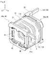
- FIG. 4 is a schematic perspective view showing a state in which a coil and a holding member used in the reactor according to the embodiment are assembled.
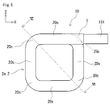
- FIG. 5 is a schematic end view of the coil used in the reactor according to the embodiment, viewed from the axial direction.
- FIG. 6 is a schematic cross-sectional view schematically showing the VI-VI cross section of FIG.
- FIG. 7 is a schematic top view schematically showing a state in which a coil and a holding member used in the reactor according to the embodiment are separated.
- FIG. 8 is a schematic diagram illustrating the configuration of a bending portion in a winding machine used for manufacturing the coil used in the reactor according to the embodiment.
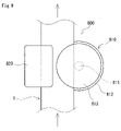
- FIG. 9 is a schematic diagram explaining the operation of the bending section.
- FIG. 10 is another schematic diagram for explaining the operation of the bending section.
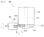
- FIG. 11 is a schematic diagram for explaining a method of manufacturing a coil used in the reactor according to the embodiment.
- 12 is a schematic top view schematically showing a state in which a coil, a magnetic core, and a holding member used in the reactor according to the embodiment are assembled;
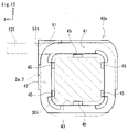
- FIG. 13 is a schematic end view of the first holding member shown in FIG. 4 as viewed from the first surface side.
- FIG. 14 is a schematic perspective view of the first holding member shown in FIG.
- FIG. 15 is a schematic top view of the first holding member shown in FIG. 4;
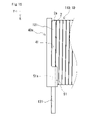
- FIG. 16 is a schematic perspective view of the second holding member shown in FIG. 4 as seen from the opposite side of FIG. 4.
- FIG. 17 is a schematic end view of the second holding member shown in FIG. 4 as viewed from the first surface side;
- FIG. 18 is a configuration diagram schematically showing a power supply system of a hybrid vehicle.
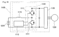
- FIG. 19 is a circuit diagram showing an outline of an example of a power converter including a converter.
- a bus bar is a member that electrically connects an external electric circuit and a coil.
- the position of the end portion of the coil may not be sufficiently regulated.
- the end portion may be displaced in the direction away from the contact surface. If the position of the end portion is not determined, the end portion and the bus bar may be separated from each other and cannot be welded, or even if they can be welded, the joint strength may be insufficient. Deterioration of the workability of connecting the end portions of the coil and the bus bar can lead to a decrease in the productivity of devices such as converters equipped with reactors.
- the reactor of the present disclosure can regulate the position of the terminal portion of the coil.
- the converter of the present disclosure and the power converter of the present disclosure are excellent in productivity.
- a reactor includes an edgewise coil made of a rectangular wire, a magnetic core on which the coil is arranged, and a holding member arranged on at least one end of the coil.
- the coil has a main body portion composed of a plurality of turns, and a first end portion drawn out from one end of the main body portion in a direction along the end face of the main body portion
- the holding member has a first surface facing the end surface of the main body and a fixing portion that holds the first terminal portion, and the fixing portion has a slit that penetrates the first terminal portion.
- the reactor of the present disclosure can regulate the position of the first terminal portion of the coil by the holding member.
- the position of the first terminal portion is restricted by inserting the first terminal portion into the slit formed in the fixed portion at the end portion of the main body portion of the coil. This improves the positional accuracy of the first terminal portion, thereby improving the workability of connecting the bus bar to the first terminal portion. In particular, it is effective in automating the work of connecting the end portions of the coils and the busbars.
- the holding member can be easily attached to the end of the main body by sliding it along the end surface of the main body. By sliding the holding member, the first end can be inserted into the slit.
- each of the plurality of turns includes an inner peripheral portion forming an inner peripheral side of the turn on the flat wire and an outer peripheral side of the turn on the flat wire.
- the outer peripheral portion may be bent with respect to the inner peripheral portion so as to be inclined toward the first direction in the axial direction of the main body portion.
- the first terminal portion at the end portion of the body portion can be opened in the first direction in the state of only the coil.
- the holding member is slid and attached to the end of the main body, the first end portion can be easily inserted into the slit. Therefore, workability of assembling the holding member to the coil is improved.
- each of the plurality of turns has a corner portion formed by bending the rectangular wire, and the main body of the inner peripheral portion and the outer peripheral portion at the corner portion
- the axial displacement amount of the portion may be 0.1 mm or more and 0.5 mm or less.
- the configuration of (3) above facilitates opening the first terminal portion in the first axial direction of the main body portion.
- the first surface may have a first region.
- the first region presses a turn in contact with the first surface among the plurality of turns in a second axial direction of the main body.
- the first terminal portion is corrected in the direction along the end surface of the main body portion by pressing the turn in contact with the first surface in the second direction. This improves the positional accuracy of the first terminal portion.
- the magnetic core has an inner core portion disposed inside the main body portion, and the holding member includes the inner core portion and an inner protrusion disposed between the body portion and the inner core portion.
- the inner projection can maintain the distance between the main body and the inner core.
- a converter according to an embodiment of the present disclosure includes the reactor according to any one of (1) to (5) above.
- the converter of the present disclosure is provided with the above-described reactor, thereby facilitating the work of connecting the terminal portion of the coil and the bus bar. Therefore, the converter of the present disclosure has excellent productivity.
- a power converter according to an embodiment of the present disclosure includes the converter described in (6) above.
- the power conversion device of the present disclosure has excellent productivity by including the above converter.
- the reactor 100 includes a coil 10, a magnetic core 30, and a holding member 40, as shown in FIGS.
- the coil 10 has a body portion 110 and terminal portions 130, as shown in FIG.
- the terminal unit 130 has a first terminal unit 131 and a second terminal unit 132 .
- a holding member 40 is arranged at the end of the coil 10 .
- the holding member 40 includes a first holding member 40a and a second holding member 40b.
- One of the features of the reactor 100 is that the first terminal portion 131 and the first holding member 40a have specific structures. The configuration of reactor 100 will be described in detail below.
- FIG. A coil 10 is an edgewise coil made of a rectangular wire 1 .
- FIG. 3 shows a state before the second terminal portion 132 is bent flatwise in the axial direction of the coil 10 and before the coil 10 is shaped as shown in FIG.
- FIG. 5 is a view of the coil 10 shown in FIG. 3 as viewed in the axial direction of the coil 10 from the first end portion 121 side.
- illustration of the second terminal portion 132 is omitted.
- the side on which the terminal unit 130 is provided is taken as the top.
- the end surface of the coil 10 on the side of the first end 121 is defined as the front, and the end surface of the coil 10 on the side of the second end 122 is defined as the back.
- the right side is right and the left side is left.
- arrow X indicates the right direction
- arrow Y indicates the axial direction
- arrow Z indicates the upward direction.
- the rectangular wire 1 is a wire having a rectangular cross section.
- the cross section is a cross section perpendicular to the longitudinal direction of the flat wire 1 .
- the rectangle has a pair of short sides and a pair of long sides like the rectangular wire 1 shown in FIG.
- the width of the flat wire 1 is the distance between the short sides facing each other and corresponds to the length of the long side.
- the width direction of the rectangular wire 1 is substantially along the long side of the rectangle.
- the thickness of the rectangular wire 1 is the distance between the long sides facing each other and corresponds to the length of the short sides.
- the thickness direction of the flat wire 1 is substantially along the short side of the rectangle.
- the width and thickness of the rectangular wire 1 can be appropriately selected.
- the width of the rectangular wire 1 is, for example, 3 mm or more and 15 mm or less, and further 5 mm or more and 12 mm or less.
- the thickness of the rectangular wire 1 is, for example, 0.5 mm or more and 5 mm or less, and further 0.8 mm or more and 3 mm or less.
- the body portion 110 is a portion formed in a spiral shape by edgewise winding the rectangular wire 1 .
- the body portion 110 is composed of a plurality of turns 2 .
- Body portion 110 includes a first end portion 121 and a second end portion 122 .
- the first end portion 121 is one end portion of the body portion 110 in the axial direction.
- the second end portion 122 is the other end portion of the body portion 110 in the axial direction.
- the shape of the body part 110 may be cylindrical or rectangular.
- the term “cylindrical” means that the shape of the end surface of the main body 110 viewed from the axial direction is circular.
- the circular shape includes not only a true circular shape but also an elliptical shape.
- the square tubular shape means that the shape of the end face is polygonal. Polygonal shapes are, for example, triangular, quadrangular, hexagonal, and octagonal.
- a square shape includes a rectangular shape and a trapezoidal shape.
- a rectangular shape includes a square shape.
- the body portion 110 has a rectangular tubular shape.
- the end face of the body portion 110 is rectangular.
- each turn 2 is substantially the same as the shape of the end surface of the body portion 110 described above.
- the shape of the turn 2 is the shape of the turn 2 viewed from the axial direction. In this embodiment, as shown in FIG. 5, the turn 2 has a rectangular shape.
- the turn 2 has four straight portions 20s in which the flat wire 1 is linearly arranged and four corner portions 20c in which the flat wire 1 is bent.
- the number of turns 2 can be selected as appropriate.
- the number of turns 2 is, for example, 10 turns or more and 60 turns or less, and further 20 turns or more and 50 turns or less.
- the terminal portion 130 is a portion where the rectangular wire 1 is pulled out from the end portion 120 in the axial direction of the main body portion 110 .
- Terminal portion 130 protrudes outward from the contour of body portion 110 .
- a first terminal portion 131 of the terminal portion 130 is pulled out from the first end portion 121 .
- the second terminal portion 132 is pulled out from the second end portion 122 .
- Bus bars 61 and 62 are connected to the first terminal portion 131 and the second terminal portion 132, as shown in FIG.
- the first terminal portion 131 is pulled out in a direction along the end surface of the main body portion 110 on the first end portion 121 side. A direction along the end surface of the body portion 110 intersects with the axial direction of the body portion 110 .
- the first terminal portion 131 is connected to the first end portion turn 2 a located on the first end portion 121 side among the plurality of turns 2 forming the body portion 110 .
- the first end turn 2a constitutes an end face on the first end 121 side.
- the first end portion 131 is drawn out along the extending direction of the upper straight portion 20s of the first end turn 2a.
- the first terminal portion 131 extends rightward continuously from the straight portion 20s.
- the first terminal portion 131 is bent edgewise in a direction orthogonal to the axial direction of the main body portion 110, and the first terminal portion 131 is pulled out so as to be orthogonal to the extending direction of the straight portion 20s.
- the second terminal portion 132 is connected to the second end portion turn 2 b positioned on the second end portion 122 side among the plurality of turns 2 forming the body portion 110 .
- the second end turn 2b constitutes the end face on the second end 122 side.
- the second terminal portion 132 is pulled out in the axial direction of the main body portion 110 before the reactor 100 is assembled as shown in FIG.
- the second terminal portion 132 may be pulled out in a direction along the end surface of the body portion 110 on the second end portion 122 side, like the first terminal portion 131 . In this case, as shown in FIG. 3, the second end portion 132 is pulled out leftward continuously from the upper straight portion of the second end turn 2b.
- FIG. 6 shows only a cross section along the line VI-VI of FIG. In FIG. 6, the configuration seen behind the cut surface is omitted.
- the line VI-VI in FIG. 5 is the diagonal of turn 2 .
- One of the features of the coil 10 is that the rectangular wire 1 forming the turns 2 in the main body 110 has a specific shape.
- 6 and 7 schematically show the configuration of the coil 10 and the configuration of the holding member 40 in a simplified manner.
- FIG. 7 shows the state of only the coil 10 without the holding member 40 assembled. The holding member 40 will be described later.
- each of the plurality of turns 2 forming the body portion 110 has an inner peripheral portion 1i and an outer peripheral portion 1e.
- the inner peripheral portion 1 i constitutes the inner peripheral side of the turn 2 in the rectangular wire 1 .
- the outer peripheral portion 1 e constitutes the outer peripheral side of the turn 2 in the rectangular wire 1 .
- the outer peripheral portion 1e is bent toward the first axial direction of the body portion 110 with respect to the inner peripheral portion 1i. In other words, the flat wire 1 forming the turn 2 is bent in the middle of the width direction of the flat wire 1 .
- the inner peripheral portion 1i and the outer peripheral portion 1e are connected via the bent portion 1b.
- the inner peripheral portion 1i is a portion of the flat wire 1 positioned closer to the inner peripheral side of the turn 2 than the bent portion 1b.
- the outer peripheral portion 1e is a portion of the flat wire 1 positioned closer to the outer peripheral side of the turn 2 than the bent portion 1b.
- the rectangular wire 1 in the turn 2 is bent halfway in the width direction at both the corner portion 20c and the straight portion 20s shown in FIG.
- the inner peripheral portion 1i extends substantially radially from the inner peripheral side of the turn 2 toward the outer peripheral side when viewed in cross section along the axial direction of the main body portion 110 . That is, the inner peripheral portion 1i extends substantially parallel to the radial direction of the turn 2. As shown in FIG. The deviation of the inner peripheral portion 1i from the radial direction due to the winding pitch of the rectangular wire 1 is considered to be along the radial direction.
- the first direction is the direction from the other axial end of the body portion 110 to the one axial end. That is, the first direction is the direction from the second end 122 toward the first end 121 .
- the first direction corresponds to the direction from the back to the front. In FIG. 6, the first direction is from top to bottom. That is, the outer peripheral portion 1e is inclined downward with respect to the inner peripheral portion 1i.
- the length of the inner peripheral portion 1i in the width direction of the flat wire 1 is, for example, 30% or more and 75% or less, further 40% or more and 70% or less of the width of the flat wire 1.
- the length of the outer peripheral portion 1e in the width direction of the flat wire 1 is, for example, 25% or more and 70% or less of the width of the flat wire 1, and further 30% or more and 60% or less.
- a displacement amount 1d in the axial direction of the body portion 110 between the inner peripheral portion 1i and the outer peripheral portion 1e is, for example, 0.1 mm or more and 0.5 mm or less, and further 0.2 mm or more and 0.4 mm or less.
- the displacement amount 1d is the displacement amount at the corner of the turn 2 .
- the amount of displacement in the straight portion of turn 2 may be smaller than the amount of displacement in the corner portion.
- the corner portion is the corner portion 20c shown in FIG.
- the linear portion is the linear portion 20s shown in FIG.
- All the displacement amounts 1d may be the same in a plurality of turns 2. Of the plurality of turns 2 , the displacement amount 1 d of some turns 2 may differ from the displacement amount 1 d of at least some of the remaining turns 2 .
- the displacement amount 1d can be measured as follows using, for example, a laser rangefinder.
- the coil 10 is placed on a horizontal table so that the axial direction of the main body 110 is vertical.
- the coil 10 is arranged so that the first end portion 121 faces downward and the second end portion 122 faces upward.
- the distance from the reference position above the coil 10 to the intersection of the upper surface and the side surface of the inner peripheral portion 1i is measured. Let this distance be the first distance.
- the side surface of the inner peripheral portion 1i is the inner peripheral surface of the turn 2 and is a surface corresponding to one short side of the rectangle in the cross section of the rectangular wire 1 .
- the distance from the reference position to the intersection of the upper surface and the side surface of the outer peripheral portion 1e is measured. Let this distance be the second distance.
- the side surface of the outer peripheral portion 1e is the outer peripheral surface of the turn 2 and corresponds to the other short side of the rectangle in the cross section of the rectangular wire 1. As shown in FIG. The difference between the first distance and the second distance is defined as displacement 1d. Then, the displacement 1d at all the corners 20c of the turn 2 is measured. In this embodiment, the displacement 1d of each of the four corners 20c shown in FIG. 5 is measured. The average value of the measured displacement amounts 1d at all the corner portions 20c is taken as the displacement amount 1d at the turn 2.
- the rectangular wire 1 forming the turn 2 is bent midway in the width direction.
- the first end portion 131 of the first end portion 121 is opened in the first axial direction of the body portion 110 .
- the first end turn 2a connected to the first terminal portion 131 is separated from the turn 2 adjacent to the first end turn 2a. The reason why the first terminal portion 131 opens in the first direction in this manner will be described later in the coil manufacturing method.
- the rectangular wire 1 forming the turns 2 is bent midway in the width direction, so that the gap 2g between the turns 2 can be reduced. The reason why the gap 2g becomes smaller will be explained later in the coil manufacturing method.
- the gap 2g is, for example, 0.076 mm or less, further 0.06 mm or less, or 0.05 mm or less.
- the gap 2g can be obtained as an average value of the gaps 2g between all the turns 2 except for the first end turn 2a.
- the gap 2g is obtained as [(L 1 ⁇ n 1 ⁇ t)/(n 1 ⁇ 1)].
- L1 is the length (mm) of the body portion 110 not including the first end turn 2a.
- n1 is the number of turns 2 excluding the first end turn 2a.
- t is the thickness (mm) of the rectangular wire 1;
- the length L1 of the body portion 110 is measured as follows. A straight line parallel to the axial direction of the body portion 110 is drawn at any position in the circumferential direction of the outer peripheral surface of the body portion 110 . This straight line is an imaginary straight line in contact with the outer peripheral surface of turn 2 . Among the turns 2 on the straight line, the distance between the turns 2 located at both ends of the main body 110 except for the first end turn 2a is obtained. Let this distance be the length L1.
- the length L1 of the main body 110 may be measured by placing the coil 10 on a horizontal table so that the axial direction of the main body 110 is horizontal. The measurement is performed with no load applied to the main body 110 .
- the number n1 of turns 2 is the number of turns 2 intersecting the straight line minus the first end turns 2a. (n 1 -1) represents the number of gaps 2g between turns 2 that do not include the first end turn 2a.
- Coil manufacturing method Mainly referring to FIGS. 8 to 12, a method for manufacturing the coil 10 described above will be described.
- Coil 10 can be manufactured using a winding machine.
- a known winding machine can be used as the winding machine.
- the winding machine includes a bending section 800 shown in FIG. 8 and a feed mechanism (not shown).
- the bending section 800 bends the rectangular wire 1 edgewise.
- the feeding mechanism feeds out the rectangular wire 1. - ⁇
- the bending section 800 is one of the main parts of the winding machine.
- the bending portion 800 has a holding portion 810 and a guide portion 820, as shown in FIGS.
- the holding portion 810 holds the inner peripheral portion 1 i of the rectangular wire 1 .
- the inner peripheral portion 1i of the flat wire 1 is a portion located on the inner peripheral side of the bending of the flat wire 1 when the flat wire 1 is edgewise bent.
- the guide portion 820 holds the outer peripheral portion 1 e of the rectangular wire 1 .
- the outer peripheral portion 1e of the flat wire 1 is a portion of the flat wire 1 located on the outer peripheral side of the bend.
- the holding portion 810 has a shaft 811 and a support 812 that supports the shaft 811 .
- the shaft 811 is a cylindrical member that contacts the side surface of the inner peripheral portion 1 i of the rectangular wire 1 .
- a side surface of the inner peripheral portion 1i is a surface corresponding to one short side of the rectangle in the cross section of the rectangular wire 1.
- Support 812 is cylindrical.
- Shaft 811 passes through the center of support 812 .
- the shaft 811 is slidable in the axial direction of the shaft 811 with respect to the support 812 .
- the tip of the shaft 811 protrudes from the end surface of the support 812 .
- a disc-shaped flange 813 is provided at the tip of the shaft 811 .
- the support 812 and the flange 813 are spaced apart.
- the holding portion 810 has a first surface 812f constituted by the end surface of the support 812 and a second surface 813f constituted by the surface of the flange 813 facing the support 812.
- the first surface 812f and the second surface 813f are arranged to face each other so as to sandwich the inner peripheral portion 1i of the rectangular wire 1 in the thickness direction.
- the inner peripheral portion 1i of the rectangular wire 1 is passed between the first surface 812f and the second surface 813f and held.
- a slight clearance is provided between the first surface 812f and the inner peripheral portion 1i and between the second surface 813f and the inner peripheral portion 1i so that the rectangular wire 1 can pass through when the rectangular wire 1 is fed out. It is
- the guide portion 820 is rotatable around the central axis of the shaft 811 .
- a guide groove 821 is formed in the guide portion 820 so as to sandwich the inner peripheral portion 1i of the rectangular wire 1 in the thickness direction.
- the outer peripheral portion 1e of the rectangular wire 1 is passed through the guide groove 821 and held.
- the width of the guide groove 821 is slightly larger than the thickness of the outer peripheral portion 1e of the rectangular wire 1 so that the rectangular wire 1 can pass through when the rectangular wire 1 is fed.
- the guide portion 820 can slide in the axial direction of the shaft 811 with respect to the holding portion 810 .
- the position of the guide portion 820 is controlled by, for example, a driving device (not shown).
- the drive device is, for example, a servomotor.
- FIGS. 3 and 5 are views of the bent portion 800 in the axial direction of the shaft 811 from the flange 813 side, that is, from the lower side of FIG.
- the rectangular wire 1 is linearly fed by a feeding mechanism (not shown). Arrows in FIG. 9 indicate the feeding direction of the rectangular wire 1 .
- the guide portion 820 rotates about the central axis of the shaft 811 .
- the side surface of the inner peripheral portion 1 i is pressed against the outer peripheral surface of the shaft 811 , and the rectangular wire 1 is bent along the outer peripheral surface of the shaft 811 .
- corners are formed by bending the rectangular wire 1 edgewise.
- the rectangular wire 1 is bent by 90 degrees by rotating the guide portion 820 by 90 degrees.
- Rectangular turns 2 are formed by repeating feeding out the rectangular wire 1 and edgewise bending four times.
- the coil 10 is formed by forming a plurality of turns 2 .
- the support 812 and the flange 813 are held at a distance such that a gap is formed between the flat wire 1 and the inner peripheral portion 1i of the flat wire 1.
- the support 812 and the flange 813 are closed so as to sandwich the inner peripheral portion 1i of the flat wire 1 from above and below.
- the inner peripheral side of the bending deforms so as to swell in the thickness direction, and the inner peripheral portion 1i becomes thicker.
- the positional relationship between the holding portion 810 and the guide portion 820 is such that the inner peripheral portion 1i of the rectangular wire 1 in the axial direction of the shaft 811 is and the position for holding the outer peripheral portion 1e of the rectangular wire 1 are set so as to substantially coincide with each other. That is, the guide portion 820 is positioned with respect to the holding portion 810 so that the inner peripheral portion 1i and the outer peripheral portion 1e of the rectangular wire 1 are flat. The position of the guide portion 820 at this time is the reference position of the guide portion 820 .
- the reference position is the center line between the first surface 812f and the second surface 813f when the holding portion 810 holds the inner peripheral portion 1i of the rectangular wire 1, and the center of the width of the guide groove 821 of the guide portion 820. This is the position where the line is aligned.
- a method for manufacturing the coil 10 uses a winding machine having the bending portion 800 described above.
- a method of manufacturing the coil 10 includes a step of spirally winding a rectangular wire 1 edgewise to form a plurality of turns 2 .
- One of the features of the method of manufacturing the coil 10 is that the turn 2 is formed while the guide portion 820 is displaced in a specific direction with respect to the holding portion 810 as shown in FIG. In the following description, FIGS. 5 to 7 will be referred to as appropriate.
- the winding is started from the first end portion 121 side of the main body portion 110 . That is, first, the first end turn 2a is formed.
- the flat wire 1 is sent out by the length corresponding to the first end portion 131 shown in FIGS.
- the feeding amount of the flat wire 1 at this time is the length including the first terminal portion 131 and one straight portion 20s.
- the rectangular wire 1 is bent edgewise to form the corner portion 20c.
- the flat wire 1 is repeatedly fed out and edgewise bent to form the first end turn 2a. This operation is then repeated to form turns 2 in succession.
- a body portion 110 is formed by forming a predetermined number of turns 2 .
- the rectangular wire 1 is sent out by the length that will become the second end portion 132 .
- the step of forming the turn 2 is performed with the guide portion 820 displaced relative to the holding portion 810 in the first axial direction of the shaft 811 .
- the guide portion 820 is displaced downward with respect to the holding portion 810 . That is, the first direction is the direction from top to bottom in FIG.
- the rectangular wire 1 can be bent so that the outer peripheral portion 1e of the rectangular wire 1 is inclined downward with respect to the inner peripheral portion 1i.
- the displaced state of the guide portion 820 is maintained while the turn 2 is being formed. That is, the positional relationship between the holding portion 810 and the guide portion 820 is maintained. Since the support 812 and the flange 813 sandwich the inner peripheral portion 1i of the rectangular wire 1 during edgewise bending, the rectangular wire 1 is bent at the corner portion 20c of the turn 2. FIG. On the other hand, when the flat wire 1 is sent out, the support 812 and the flange 813 are held at such a distance that a gap is formed between them and the inner peripheral portion 1i of the flat wire 1 .
- the guide portion 820 is kept displaced by the length corresponding to the first terminal portion 131 and the length corresponding to the second terminal portion 132 even when the rectangular wire 1 is fed.
- the rectangular wire 1 forming the turn 2 is bent midway in the width direction.
- the gap 2g between the turns 2 can be reduced.
- the displacement amount 1d may be, for example, 0.2 mm or more and 0.4 mm or less.
- the first terminal portion 131 at the first end portion 121 is opened in the first axial direction of the body portion 110 as shown in FIG. become. Specifically, the first end turn 2a connected to the first terminal portion 131 is separated from the turn 2 adjacent to the first end turn 2a.
- the reason why the first terminal unit 131 is in the open state is considered as follows.
- the flat wire 1 is fed out by the length of the first end portion 131 .
- the first terminal portion 131 and the linear portion 20s connected to the first terminal portion 131 are linear.
- the first terminal portion 131 can easily be opened in the first direction.
- the displacement amount 1d of the turn 2 may be 0.2 mm or more.
- the amount of displacement Gd of the guide part 820 with respect to the holding part 810 may be, for example, 0.1 mm or more and 0.5 mm or less, or even 0.2 mm or more and 0.4 mm or less.
- the displacement amount Gd of the guide portion 820 is the distance by which the guide portion 820 is slid in the axial direction of the shaft 811 from the reference position described above.
- the amount of displacement Gd is the amount of displacement in the first direction, that is, downward.
- the width of the inner peripheral portion 1i of the flat wire 1 held by the holding portion 810 is, for example, 30% or more and 75% or less, further 40% or more and 70% or less of the width of the flat wire 1.
- the width of the outer peripheral portion 1e of the flat wire 1 held by the guide portion 820 is, for example, 25% or more and 70% or less of the width of the flat wire 1, and further 30% or more and 60% or less.
- the configuration of the magnetic core 30 will be described with reference to FIGS. 1 and 2.
- FIG. The coil 10 is arranged on the magnetic core 30 .
- the magnetic core 30 in this embodiment is configured in a ⁇ shape as a whole.
- the magnetic core 30 has a middle core portion 300 , a first end core portion 310 , a second end core portion 320 , a first side core portion 330 and a second side core portion 340 .
- the magnetic core 30 is a combination of a first core 31 and a second core 32 .
- the first core 31 and the second core 32 will be described later.
- the middle core portion 300 is a portion of the magnetic core 30 that is arranged inside the coil 10 . That is, the middle core portion 300 corresponds to the inner core portion.
- the middle core portion 300 is divided into two parts in the longitudinal direction of the middle core portion 300 and has a first middle core portion 301 and a second middle core portion 302 .
- a gap portion 30g is provided in the middle of the middle core portion 300 in the longitudinal direction.
- Gap portion 30 g is arranged between first middle core portion 301 and second middle core portion 302 .
- the gap portion 30g may be an air gap, or may be a plate member made of a non-magnetic material such as resin or ceramics. Unlike the present embodiment, the middle core portion 300 may not be provided with the gap portion 30g.
- the first end core portion 310 is a portion of the magnetic core 30 that faces the first end portion 121 of the coil 10 .
- the second end core portion 320 is a portion facing the second end portion 122 of the coil 10 .
- the first end core portion 310 and the second end core portion 320 are spaced apart so as to sandwich the coil 10 from the axial direction.
- the first side core portion 330 and the second side core portion 340 are portions of the magnetic core 30 that are arranged outside the coil 10 so as to sandwich the middle core portion 300 .
- the first side core portion 330 and the second side core portion 340 are arranged with an interval therebetween so as to sandwich both side surfaces along the axial direction of the coil 10 .
- the first side core portion 330 and the second side core portion 340 have lengths that connect the first end core portion 310 and the second end core portion 320 .
- the magnetic core 30 is configured by combining a first core 31 and a second core 32 .
- the shape of each of the first core 31 and the second core 32 can be selected from various combinations.
- the magnetic core 30 is an ET type in which an E-shaped first core 31 and a T-shaped second core 32 are combined.
- Other combinations are, for example, EU type, EI type and TU type.
- the first core 31 includes the first end core portion 310, the first middle core portion 301 that is part of the middle core portion 300, and all of the first side core portion 330 and the second side core portion 340. include.
- the first end core portion 310, the first middle core portion 301, the first side core portion 330, and the second side core portion 340 are integrally formed.
- the second core 32 includes a second end core portion 320 and a second middle core portion 302 which is the remainder of the middle core portion 300 .
- the second end core portion 320 and the second middle core portion 302 are integrally molded.
- FIG. 12 schematically shows a simplified configuration of the coil 10, the holding member 40, and the magnetic core 30.
- FIG. 12 shows only the inner core portion 30i of the magnetic core 30, which is arranged inside the coil 10.
- FIG. The inner core portion 30 i corresponds to the middle core portion 300 of the magnetic core 30 .
- holding members 40 are arranged at both ends of the coil 10 .
- the first holding member 40 a is arranged at the first end portion 121 of the body portion 110 .
- a second retaining member 40 b is arranged at the second end 122 of the coil 10 .
- the first holding member 40a is arranged between the end face of the body portion 110 on the first end portion 121 side and the first end core portion 310 of the magnetic core 30, as shown in FIG.
- the first holding member 40 a ensures electrical insulation between the body portion 110 and the first end core portion 310 .
- FIG. 13 is a diagram of the first holding member 40a viewed from the inside.
- FIG. 14 is a perspective view of the first holding member 40a as seen from the inside.
- the inner side of the first holding member 40a is the side facing the end face of the main body portion 110 on the first end portion 121 side shown in FIG.
- the inner side of the first holding member 40a faces the first end turn 2a.
- the outer side of the first holding member 40 a faces the first end core portion 310 .
- the inner side of the first holding member 40a is the rear side.
- the outside of the first holding member 40a is the front side.
- the first terminal portion 131 and the first end turn 2a are indicated by two-dot chain lines.
- some turns 2 including the first end turn 2a are indicated by solid lines.
- the first holding member 40a is a frame-shaped member.
- the shape of the first holding member 40 a is a shape corresponding to the end face of the main body portion 110 .
- the first holding member 40a has a rectangular frame shape.
- the first retaining member 40 a has a first surface 41 . As shown in FIG. 13, the first surface 41 faces the first end turn 2a forming the end surface of the main body 110 on the first end 121 side.
- the first surface 41 has a first area 42 .
- the first region 42 is a region of the first surface 41 that contacts the first end turn 2a.
- the first region 42 presses the first end turn 2 a contacting the first surface 41 in the second axial direction of the body portion 110 .
- the second direction is opposite to the first direction described above. That is, the second direction is the direction from the first end 121 to the second end 122 . In other words, the second direction is the direction that brings the first end turn 2a closer to the adjacent turn 2. As shown in FIG.
- the second direction corresponds to the direction from the front to the back.
- the first region 42 is spirally inclined so as to correspond to the first end turn 2a.
- the first region 42 allows the first end turn 2a to be pressed in the second direction.
- the first end portion 131 is corrected in a direction perpendicular to the axial direction of the body portion 110 .
- the first holding member 40 a has a fixing portion 51 .
- the fixed portion 51 holds the first terminal portion 131 .
- the fixing portion 51 is formed at a portion where the first terminal portion 131 is pulled out from the first end turn 2a. In this embodiment, as shown in FIG. 4, the fixing portion 51 is provided at the upper right corner when the first holding member 40a is viewed from the front.
- the right side of the first holding member 40a is, for example, the right side of the paper surface in FIG. In the case of FIG. 13, it is on the left side of the paper surface.
- the fixing portion 51 covers part of the outer peripheral surface of the first end portion 121 of the main body portion 110 .
- the fixed part 51 has a slit 51s.
- the slit 51s penetrates through the first terminal portion 131 .
- the slit 51 s extends in a direction orthogonal to the axial direction of the body portion 110 .
- the slit 51s opens on the side surface of the first holding member 40a.
- the shape of the opening of the slit 51s is a shape corresponding to the cross section of the flat wire 1 .
- the opening shape of the slit 51s is the shape of the contour of the slit 51s as seen from the axial direction of the slit 51s. In this embodiment, the opening shape of the slit 51s is rectangular.
- the slit 51s allows to have a clearance for inserting the first terminal portion 131 .
- the fixed portion 51 is not intended to hold the first terminal portion 131 completely immobile. That is, the first terminal portion 131 is allowed to move in the axial direction of the main body portion 110 within the slit 51s to the extent that the connection between the first terminal portion 131 and the busbar 61 is not hindered.
- the slit 51 s is formed so as to surround the entire circumference of the first terminal portion 131 . As shown in FIG. 15, of the inner peripheral surfaces of the slit 51s, the surface located on the side of the first surface 41 is flush with the first surface 41. As shown in FIG. 15, of the inner peripheral surfaces of the slit 51s, the surface located on the side of the first surface 41 is flush with the first surface 41. As shown in FIG. 15, of the inner peripheral surfaces of the slit 51s, the surface located on the side of the first surface 41 is flush with the first surface 41. As shown in FIG.
- the first holding member 40 a has a through hole 43 .
- An end portion of the inner core portion 30 i shown in FIG. 12 is inserted into the through hole 43 .
- the shape of the through hole 43 is a shape that generally corresponds to the outer peripheral shape of the end portion of the inner core portion 30i. In this embodiment, the shape of the through-hole 43 is rectangular.
- the first retaining member 40a has an inner projection 45. As shown in FIG.
- the inner projection 45 is arranged between the main body portion 110 and the inner core portion 30i.
- the inner protrusion 45 protrudes in the axial direction of the through-hole 43 from the inner peripheral surface of the first holding member 40 a forming the through-hole 43 .
- the inner core portion 30i is arranged inside the main body portion 110 as shown in FIG. be.
- the gap can ensure electrical insulation between main body portion 110 and middle core portion 300 .
- the inner protrusions 45 can position the first holding member 40 a with respect to the coil 10 .
- the number and positions of the inner protrusions 45 are not particularly limited.
- the inner protrusions 45 may be formed at locations corresponding to respective sides of the inner peripheral surface of the main body portion 110 .
- the inner protrusions 45 are provided on the inner peripheral surface of the first holding member 40a, one on each of the upper and lower sides, and two on each of both sides.
- FIG. 7 A method of assembling the first holding member 40a will be described with reference to FIGS. 7 and 12.
- FIG. 7 the first holding member 40 a is slid along the end surface of the body portion 110 with respect to the first end portion 121 of the body portion 110 .
- the first terminal portion 131 is inserted through the slit 51s.
- the first holding member 40 a is pressed against the first end portion 121 of the body portion 110 to fit the first holding member 40 a into the first end portion 121 .
- the first holding member 40a can be assembled to the first end portion 121 of the body portion 110, as shown in FIG.
- the first terminal portion 131 can be easily inserted into the slit 51s.
- the first end turn 2a is elastically deformed by being pressed by the first holding member 40a, and the first end portion 131 is closed.
- the first end turn 2a is shown separated from the adjacent turns 2, but in reality, the first end turn 2a is pressed against the first holding member 40a.
- the first end turn 2a is in contact with adjacent turns 2. As shown in FIG.
- the second holding member 40b is arranged between the end surface of the body portion 110 on the side of the second end portion 122 and the second end core portion 320 of the magnetic core 30, as shown in FIG.
- the second holding member 40 b ensures electrical insulation between the body portion 110 and the second end core portion 320 .
- FIG. 16 is a perspective view of the second holding member 40b as seen from the outside.
- FIG. 17 is a view of the second holding member 40b as seen from the inside.
- the inside of the second holding member 40b is the side facing the end surface of the main body 110 on the side of the second end 122 shown in FIG.
- the inner side of the second holding member 40b faces the second end turn 2b.
- the outer side of the second holding member 40 b faces the second end core portion 320 .
- the inside of the second holding member 40b is the front side.
- the outside of the second holding member 40b is the rear side.
- the second terminal portion 132 and the second end turn 2b are indicated by two-dot chain lines.
- the configuration of the second holding member 40b is the same as the configuration of the first holding member 40a described above. Below, the second holding member 40b will be described, focusing on the differences from the first holding member 40a. Configurations common to the first holding member 40a are denoted by the same reference numerals, and detailed description thereof is omitted.
- the second holding member 40b is a frame-shaped member.
- the shape of the second holding member 40b is a rectangular frame like the first holding member 40a.
- the second retaining member 40 b has a first surface 41 . As shown in FIG. 17, the first surface 41 faces the second end turn 2b that forms the end surface of the main body 110 on the second end 122 side.
- the first face 41 like the first retaining member 40a, has a first region 42 that contacts the second end turn 2b.
- the first region 42 presses the second end turn 2 b contacting the first surface 41 in the first axial direction of the body portion 110 .
- the first direction is the direction from the second end 122 toward the first end 121 . In other words, the first direction is the direction that brings the second end turn 2b closer to the adjacent turn 2.
- the first region 42 is spirally inclined so as to correspond to the second end turn 2b.
- the second holding member 40 b has a fixing portion 52 .
- the fixed portion 52 holds the second terminal portion 132 .
- the fixing portion 52 is formed at a portion where the second terminal portion 132 is pulled out from the second end turn 2b.
- the fixing portion 52 is provided at the upper left corner when the second holding member 40b is viewed from the front.
- the left side of the second holding member 40b is, for example, the right side of the drawing in FIG. In FIG. 17, it is on the left side of the paper surface.
- the fixing portion 52 axially protrudes from the outer surface of the second holding member 40b.
- the fixed part 52 has a slit 52s.
- the slit 52s penetrates through the second terminal portion 132 .
- the slit 52s extends along the axial direction of the body portion 110 .
- the slit 51s opens on the outer surface of the second holding member 40b.
- the opening shape of the slit 52s is a shape corresponding to the cross section of the rectangular wire 1, that is, a rectangular shape.
- the slit 52 s is formed so as to surround the entire circumference of the second terminal portion 132 .
- the slit 52s is substantially orthogonal to the first surface 41.
- the slit 52s allows to have clearance for inserting the second end portion 132 .
- the fixing portion 52 is not intended to hold the second terminal portion 132 completely immobile, like the fixing portion 51 described above.
- the second holding member 40b has a through hole 43 and an inner projection 45, like the first holding member 40a.
- FIG. 7 A method of assembling the second holding member 40b will be described with reference to FIGS.
- the second holding member 40b is moved in the axial direction of the body portion 110 to insert the second terminal portion 132 into the slit 52s.
- the second holding member 40 b is pressed against the second end portion 122 of the body portion 110 to fit the second holding member 40 b into the second end portion 122 .
- the second holding member 40b can be assembled to the second end portion 122 of the body portion 110.
- FIG. 7 A method of assembling the second holding member 40b will be described with reference to FIGS.
- the holding member 40 can regulate the position of the terminal portion 130 of the coil 10 .
- the first terminal portion 131 pulled out in the direction along the end surface of the main body portion 110 is inserted into the slit 51s formed in the fixed portion 51 of the first holding member 40a. Therefore, it is possible to effectively suppress the displacement of the first terminal portion 131 in the axial direction of the main body portion 110 . Therefore, the position of the first terminal portion 131 is sufficiently restricted.
- the first holding member 40a is assembled to the first end portion 121 of the main body portion 110 by sliding in the direction along the end surface of the main body portion 110. As shown in FIG. By inserting the first terminal portion 131 into the slit 51 s, the first holding member 40 a becomes difficult to come off from the first end portion 121 . In addition, of the inner peripheral surfaces of the slits 51s, the surface located on the first surface 41 side is flush with the first surface 41, so that the first terminal portion 131 can be moved by using the first surface 41 as a guide. It is easy to insert into the slit 51s.
- the outer peripheral portion 1e of the rectangular wire 1 is inclined in the first direction with respect to the inner peripheral portion 1i. Since the flat wire 1 forming the turn 2 is bent halfway in the width direction, the first terminal portion 131 is opened in the first axial direction of the body portion 110 in the state of only the coil 10. can.
- the first holding member 40a is slid and attached to the first end portion 121, the first terminal portion 131 can be easily inserted into the slit 51s. It is easy to assemble the first holding member 40 a to the first end portion 121 .
- the rectangular wire 1 forming the turns 2 is bent in the middle in the width direction, so that the gap 2g between the turns 2 can be reduced. Since the gap 2g is small, the overall length of the body portion 110 is less likely to be shortened when the body portion 110 is pushed in the axial direction from both ends. After the holding member 40 is attached to the coil 10, the positions of the first terminal portion 131 and the second terminal portion 132 remain substantially unchanged.
- the first terminal portion 131 can be easily opened in the first direction, and the gap 2g can be reduced. easy. Since the amount of displacement 1d is 0.5 mm or less, it is difficult to understand at first glance that the rectangular wire 1 is bent in the middle in the width direction. In other words, the coil 10 can be made to look as good as the conventional one.
- the positional accuracy of the first terminal portion 131 is improved, the workability of connecting the busbar 61 to the first terminal portion 131 is improved. Since the position of the first terminal portion 131 and the position of the second terminal portion 132 are almost the same, it is easy to perform the work of connecting the terminal portions 130 of the first terminal portion 131 and the second terminal portion 132 to the bus bars 61 and 62. .
- a coil 10 was manufactured by the coil manufacturing method described in the embodiment.
- the specifications of the coil 10 to be manufactured were as follows.
- the shape of the main body portion 110 was a square tube.
- the shape of the end surface of the body portion 110 is rectangular.
- the number of turns 2 was 16 turns.
- the width of the inner peripheral portion 1i of the flat wire 1 held by the holding portion 810 is about 60% of the width of the flat wire 1.
- the width of the outer peripheral portion 1e of the flat wire 1 held by the guide portion 820 was set to about 30% of the width of the flat wire 1.
- the amount of displacement Gd of the guide portion 820 was set to 0.2 mm.
- the manufactured coil 10 is referred to as Sample No. 1.
- the amount of displacement 1d between the inner peripheral portion 1i and the outer peripheral portion 1e in the turn 2 was measured.
- the displacement amount 1d was measured using the measuring method described in the embodiment. Then, the displacement amount 1d of each of the four corners 20c was measured, and the average value was obtained. As a result, the displacement 1d at the corner 20c of the turn 2 was about 0.2 mm on average.
- the displacement amount was measured at each intermediate point of the four linear portions 20s, and the average value was obtained.
- the midpoint of the straight portion 20 s is the midpoint of the length of the straight portion 20 s along the circumferential direction of the turn 2 . As a result, the displacement amount at the straight portion 20s of the turn 2 was about 0.1 mm on average.
- the reason why the amount of displacement at the straight portion 20s is smaller than that at the corner portion 20c is considered as follows. Since the inner peripheral portion 1i of the rectangular wire 1 is sandwiched between the support 812 and the flange 813 during edgewise bending, the inner peripheral portion 1i is fixed. Therefore, the rectangular wire 1 is easily bent at the corner portion 20c. On the other hand, in the straight portion 20s, the supporting body 812 and the flange 813 are held at such a distance that a gap is formed between them and the inner peripheral portion 1i. It is difficult to apply bending force. Due to such a relationship between the flat wire 1, the holding portion 810, and the guide portion 820, it is considered that the displacement amount of the straight portion 20s is smaller than that of the corner portion 20c.
- Sample No. 1 The appearance of No. 1 was visually inspected. As a result, it was not apparent at first glance that the flat wire in turn 2 was bent in the middle of the width direction. Moreover, sample no. 1, at the first end portion 121 of the body portion 110, a gap is formed between the first end turn 2a and the turn 2 adjacent to the first end turn 2a. In other words, the first terminal portion 131 was open in the first direction. The gap between the first end turn 2a and the adjacent turn 2 is about 1.0 mm. This gap is the widest part of the gap between the first end turn 2a and the adjacent turn 2. As shown in FIG. Sample no. 1, when the first holding member 40a was assembled to the first end portion 121 of the main body portion 110, the assembly could be easily performed.
- sample No. A coil was manufactured under the same manufacturing conditions as in 1. This coil is sample No. 10.
- Sample No. 10 sample no. 1, at the first end portion 121 of the main body portion 110, the gap between the first end turn 2a and the turn 2 adjacent to the first end turn 2a was smaller. Therefore, the first terminal portion 131 was not sufficiently opened in the first direction.
- Sample no. 10 in order to assemble the first holding member 40a to the first end portion 121 of the main body portion 110, the first terminal portion 131 needs to be pushed apart in the direction away from the adjacent turn 2, resulting in poor assembly workability. . When the first terminal portion 131 is spread, the first terminal portion 131 may bend.
- sample No. 10 a gap of 2 g between turns 2 was measured.
- the measurement of the gap 2g was performed using the measurement method described in the embodiment. As a result, the gap 2g was 0.06 mm.
- Sample no. 1 is sample no. Compared to No. 10, the gap 2g is smaller and the dimensional stability is excellent.
- the reactor 100 of the embodiment can be used for applications that satisfy the following energization conditions.
- the energization conditions are, for example, a maximum DC current of approximately 100 A or more and 1000 A or less, an average voltage of approximately 100 V or more and 1000 V or less, and a working frequency of approximately 5 kHz or more and 100 kHz or less.
- the reactor 100 of the embodiment can be typically used as a component of a converter mounted in a vehicle such as an electric vehicle or a hybrid vehicle, or as a component of a power conversion device including this converter. Since the reactor 100 of the embodiment has excellent connection workability between the end portions 130 of the coil 10 and the bus bars 61 and 62, productivity of converters and power converters can be improved.
- a vehicle 1200 such as a hybrid vehicle or an electric vehicle is driven by a main battery 1210, a power conversion device 1100 connected to the main battery 1210, and power supplied from the main battery 1210 as shown in FIG. and a motor 1220 that Motor 1220 is typically a three-phase AC motor, drives wheels 1250 during running, and functions as a generator during regeneration.
- vehicle 1200 includes engine 1300 in addition to motor 1220 .
- an inlet is shown as the charging point of vehicle 1200, but it can be provided with a plug.
- a power conversion device 1100 has a converter 1110 connected to a main battery 1210, and an inverter 1120 connected to the converter 1110 for mutual conversion between direct current and alternating current.
- Converter 1110 shown in this example boosts the input voltage of main battery 1210 from approximately 200 V to 300 V to approximately 400 V to 700 V and supplies power to inverter 1120 when vehicle 1200 is running.
- converter 1110 steps down the input voltage output from motor 1220 via inverter 1120 to a DC voltage suitable for main battery 1210 to charge main battery 1210 .
- the input voltage is a DC voltage.
- Inverter 1120 converts the direct current boosted by converter 1110 into a predetermined alternating current and supplies power to motor 1220 when vehicle 1200 is running, and converts the alternating current output from motor 1220 into direct current during regeneration and outputs the direct current to converter 1110. is doing.
- the converter 1110 includes a plurality of switching elements 1111, a drive circuit 1112 that controls the operation of the switching elements 1111, and a reactor 1115, as shown in FIG. 19, and converts the input voltage by repeating ON/OFF. Conversion of the input voltage means stepping up and down in this case.
- a power device such as a field effect transistor or an insulated gate bipolar transistor is used for the switching element 1111 .
- the reactor 1115 has a function of smoothing the change when the current increases or decreases due to the switching operation by using the property of the coil that prevents the change of the current to flow in the circuit.
- Reactor 100 of the embodiment is provided as reactor 1115 .
- vehicle 1200 is connected to power feed device converter 1150 connected to main battery 1210, sub-battery 1230 serving as a power source for auxiliary equipment 1240, and main battery 1210 to supply the high voltage of main battery 1210.
- An accessory power supply converter 1160 for converting to low voltage is provided.
- Converter 1110 typically performs DC-DC conversion, but power supply device converter 1150 and auxiliary power supply converter 1160 perform AC-DC conversion. Some power supply converters 1150 perform DC-DC conversion.
- a reactor having the same configuration as the reactor 100 of the embodiment and having a different size, shape, etc., can be used as the reactor of the power supply device converter 1150 or the auxiliary power converter 1160 .
- the reactor 100 of the embodiment can also be used for a converter that converts input electric power, that is, a converter that only steps up or a converter that only steps down.
Landscapes
- Engineering & Computer Science (AREA)
- Power Engineering (AREA)
- Coils Of Transformers For General Uses (AREA)
- Dc-Dc Converters (AREA)
Priority Applications (2)
| Application Number | Priority Date | Filing Date | Title |
|---|---|---|---|
| US18/564,606 US20250087405A1 (en) | 2021-06-10 | 2022-06-08 | Reactor, converter, and power conversion device |
| CN202280038606.7A CN117396991A (zh) | 2021-06-10 | 2022-06-08 | 电抗器、转换器及电力转换装置 |
Applications Claiming Priority (2)
| Application Number | Priority Date | Filing Date | Title |
|---|---|---|---|
| JP2021097095A JP7558491B2 (ja) | 2021-06-10 | 2021-06-10 | リアクトル、コンバータ、及び電力変換装置 |
| JP2021-097095 | 2021-06-10 |
Publications (1)
| Publication Number | Publication Date |
|---|---|
| WO2022260089A1 true WO2022260089A1 (ja) | 2022-12-15 |
Family
ID=84426083
Family Applications (1)
| Application Number | Title | Priority Date | Filing Date |
|---|---|---|---|
| PCT/JP2022/023143 Ceased WO2022260089A1 (ja) | 2021-06-10 | 2022-06-08 | リアクトル、コンバータ、及び電力変換装置 |
Country Status (4)
| Country | Link |
|---|---|
| US (1) | US20250087405A1 (https=) |
| JP (1) | JP7558491B2 (https=) |
| CN (1) | CN117396991A (https=) |
| WO (1) | WO2022260089A1 (https=) |
Families Citing this family (1)
| Publication number | Priority date | Publication date | Assignee | Title |
|---|---|---|---|---|
| JP2024106036A (ja) * | 2023-01-26 | 2024-08-07 | 住友電装株式会社 | リアクトル、コンバータ、および電力変換装置 |
Citations (4)
| Publication number | Priority date | Publication date | Assignee | Title |
|---|---|---|---|---|
| JPH1154335A (ja) * | 1997-08-04 | 1999-02-26 | Hitachi Ferrite Electronics Ltd | インダクタンス素子 |
| JP2009206421A (ja) * | 2008-02-29 | 2009-09-10 | Fdk Corp | チョークコイル |
| JP2010219473A (ja) * | 2009-03-19 | 2010-09-30 | Fdk Corp | チョークコイル |
| JP2013026419A (ja) * | 2011-07-20 | 2013-02-04 | Sumitomo Electric Ind Ltd | リアクトル |
-
2021
- 2021-06-10 JP JP2021097095A patent/JP7558491B2/ja active Active
-
2022
- 2022-06-08 CN CN202280038606.7A patent/CN117396991A/zh active Pending
- 2022-06-08 US US18/564,606 patent/US20250087405A1/en active Pending
- 2022-06-08 WO PCT/JP2022/023143 patent/WO2022260089A1/ja not_active Ceased
Patent Citations (4)
| Publication number | Priority date | Publication date | Assignee | Title |
|---|---|---|---|---|
| JPH1154335A (ja) * | 1997-08-04 | 1999-02-26 | Hitachi Ferrite Electronics Ltd | インダクタンス素子 |
| JP2009206421A (ja) * | 2008-02-29 | 2009-09-10 | Fdk Corp | チョークコイル |
| JP2010219473A (ja) * | 2009-03-19 | 2010-09-30 | Fdk Corp | チョークコイル |
| JP2013026419A (ja) * | 2011-07-20 | 2013-02-04 | Sumitomo Electric Ind Ltd | リアクトル |
Also Published As
| Publication number | Publication date |
|---|---|
| JP2022188850A (ja) | 2022-12-22 |
| CN117396991A (zh) | 2024-01-12 |
| JP7558491B2 (ja) | 2024-10-01 |
| US20250087405A1 (en) | 2025-03-13 |
Similar Documents
| Publication | Publication Date | Title |
|---|---|---|
| US10720820B2 (en) | Rotating electric machine and method for manufacturing the rotating electric machine | |
| JP6098870B2 (ja) | リアクトル、コンバータ、及び電力変換装置 | |
| JP5109466B2 (ja) | 回転電機用ステータ、それに使用するバスバーユニット及びそのバスバー用端子とコイル端末との接続構造 | |
| JP5694748B2 (ja) | 複数相コンバータ用リアクトルユニット | |
| JP4914287B2 (ja) | インシュレータ、分割ステータ、及び回転電機用ステータ | |
| JP2014112612A (ja) | 巻線構造体、コイル巻線、コイル部品およびコイル巻線の製造方法 | |
| JP2011209158A (ja) | 電流センサ組立体およびその組立方法 | |
| CN110537319A (zh) | 旋转电机 | |
| US8866580B2 (en) | Power converting apparatus | |
| WO2022260089A1 (ja) | リアクトル、コンバータ、及び電力変換装置 | |
| JP5087880B2 (ja) | リアクトル | |
| JP2015065346A (ja) | リアクトル装置及び電力変換装置 | |
| EP1072082A1 (de) | Konstruktion einer elektrischen maschine mit einzelpolwicklungen | |
| CN113366729A (zh) | 电机结构及工艺 | |
| WO2022255429A1 (ja) | コイル、リアクトル、コンバータ、電力変換装置、及びコイルの製造方法 | |
| JP4465396B2 (ja) | 回転電機の配電接続構造および回転電機の配電接続構造の製造方法 | |
| JP2024150607A (ja) | コイル、リアクトル、コンバータ、及び電力変換装置 | |
| WO2024247671A1 (ja) | リアクトル、コンバータおよび電力変換装置 | |
| JP2015188019A (ja) | ギャップ部材、磁性コア及びリアクトル | |
| JP5252379B2 (ja) | リアクトル用コイルの製造方法 | |
| US20240258025A1 (en) | Reactor, converter, and power converter device | |
| CN115244635B (zh) | 电抗器、转换器及电力转换装置 | |
| WO2025110060A1 (ja) | リアクトル、コンバータ、および電力変換装置 | |
| WO2023008075A1 (ja) | リアクトル構造体、コンバータ、及び電力変換装置 | |
| DE112020005967T5 (de) | Rotierende elektrische Maschine |
Legal Events
| Date | Code | Title | Description |
|---|---|---|---|
| 121 | Ep: the epo has been informed by wipo that ep was designated in this application |
Ref document number: 22820268 Country of ref document: EP Kind code of ref document: A1 |
|
| DPE1 | Request for preliminary examination filed after expiration of 19th month from priority date (pct application filed from 20040101) | ||
| WWE | Wipo information: entry into national phase |
Ref document number: 18564606 Country of ref document: US |
|
| WWE | Wipo information: entry into national phase |
Ref document number: 202280038606.7 Country of ref document: CN |
|
| NENP | Non-entry into the national phase |
Ref country code: DE |
|
| 122 | Ep: pct application non-entry in european phase |
Ref document number: 22820268 Country of ref document: EP Kind code of ref document: A1 |
|
| WWP | Wipo information: published in national office |
Ref document number: 18564606 Country of ref document: US |