WO2022260089A1 - Reactor, converter, and power conversion device - Google Patents
Reactor, converter, and power conversion device Download PDFInfo
- Publication number
- WO2022260089A1 WO2022260089A1 PCT/JP2022/023143 JP2022023143W WO2022260089A1 WO 2022260089 A1 WO2022260089 A1 WO 2022260089A1 JP 2022023143 W JP2022023143 W JP 2022023143W WO 2022260089 A1 WO2022260089 A1 WO 2022260089A1
- Authority
- WO
- WIPO (PCT)
- Prior art keywords
- coil
- turn
- holding member
- main body
- core
- Prior art date
Links
- 238000006243 chemical reaction Methods 0.000 title description 13
- 230000002093 peripheral effect Effects 0.000 claims description 103
- 238000006073 displacement reaction Methods 0.000 claims description 42
- 238000005452 bending Methods 0.000 description 27
- 238000004804 winding Methods 0.000 description 13
- 238000004519 manufacturing process Methods 0.000 description 12
- 238000010586 diagram Methods 0.000 description 7
- 238000000034 method Methods 0.000 description 7
- 238000010292 electrical insulation Methods 0.000 description 3
- 238000005259 measurement Methods 0.000 description 3
- 230000008929 regeneration Effects 0.000 description 3
- 238000011069 regeneration method Methods 0.000 description 3
- 230000007423 decrease Effects 0.000 description 2
- 230000000694 effects Effects 0.000 description 2
- 238000000691 measurement method Methods 0.000 description 2
- 238000003825 pressing Methods 0.000 description 2
- 230000001105 regulatory effect Effects 0.000 description 2
- 230000015572 biosynthetic process Effects 0.000 description 1
- 239000000919 ceramic Substances 0.000 description 1
- 230000006866 deterioration Effects 0.000 description 1
- 230000005669 field effect Effects 0.000 description 1
- 238000009499 grossing Methods 0.000 description 1
- 239000000696 magnetic material Substances 0.000 description 1
- 238000012986 modification Methods 0.000 description 1
- 230000004048 modification Effects 0.000 description 1
- 239000011347 resin Substances 0.000 description 1
- 229920005989 resin Polymers 0.000 description 1
Images


Classifications
-
- H—ELECTRICITY
- H01—ELECTRIC ELEMENTS
- H01F—MAGNETS; INDUCTANCES; TRANSFORMERS; SELECTION OF MATERIALS FOR THEIR MAGNETIC PROPERTIES
- H01F27/00—Details of transformers or inductances, in general
- H01F27/28—Coils; Windings; Conductive connections
-
- H—ELECTRICITY
- H01—ELECTRIC ELEMENTS
- H01F—MAGNETS; INDUCTANCES; TRANSFORMERS; SELECTION OF MATERIALS FOR THEIR MAGNETIC PROPERTIES
- H01F37/00—Fixed inductances not covered by group H01F17/00
-
- H—ELECTRICITY
- H02—GENERATION; CONVERSION OR DISTRIBUTION OF ELECTRIC POWER
- H02M—APPARATUS FOR CONVERSION BETWEEN AC AND AC, BETWEEN AC AND DC, OR BETWEEN DC AND DC, AND FOR USE WITH MAINS OR SIMILAR POWER SUPPLY SYSTEMS; CONVERSION OF DC OR AC INPUT POWER INTO SURGE OUTPUT POWER; CONTROL OR REGULATION THEREOF
- H02M3/00—Conversion of dc power input into dc power output
- H02M3/02—Conversion of dc power input into dc power output without intermediate conversion into ac
- H02M3/04—Conversion of dc power input into dc power output without intermediate conversion into ac by static converters
- H02M3/10—Conversion of dc power input into dc power output without intermediate conversion into ac by static converters using discharge tubes with control electrode or semiconductor devices with control electrode
- H02M3/145—Conversion of dc power input into dc power output without intermediate conversion into ac by static converters using discharge tubes with control electrode or semiconductor devices with control electrode using devices of a triode or transistor type requiring continuous application of a control signal
- H02M3/155—Conversion of dc power input into dc power output without intermediate conversion into ac by static converters using discharge tubes with control electrode or semiconductor devices with control electrode using devices of a triode or transistor type requiring continuous application of a control signal using semiconductor devices only
Landscapes
- Engineering & Computer Science (AREA)
- Power Engineering (AREA)
- Coils Of Transformers For General Uses (AREA)
- Dc-Dc Converters (AREA)
Abstract
Provided is a reactor comprising: an edgewise coil which is constituted by a rectangular wire; a magnetic core around which the coil is disposed; and a holding member which is disposed at at least one end of the coil. The coil comprises: a main body part which is constituted by a plurality of turns; and a first terminal portion which is pulled out from one end of the main body part in a direction along an end surface of the main body part. The holding member comprises: a first surface which faces the end surface of the main body part; and a fixing part which holds the first terminal portion, wherein the fixing part has a slit through which the first terminal portion passes.
Description
本開示は、リアクトル、コンバータ、及び電力変換装置に関する。
本出願は、2021年06月10日付の日本国出願の特願2021-097095に基づく優先権を主張し、前記日本国出願に記載された全ての記載内容を援用するものである。 The present disclosure relates to reactors, converters, and power converters.
This application claims priority based on Japanese Patent Application No. 2021-097095 dated June 10, 2021, and incorporates all the descriptions described in the Japanese application.
特許文献1は、コイルと、コアと、枠状ボビンとを備えるリアクトルを開示する。コイルは、平角線で構成されたエッジワイズコイルである。枠状ボビンは、コイルの両端部に配置されている。
Patent Document 1 discloses a reactor that includes a coil, a core, and a frame-shaped bobbin. The coil is an edgewise coil made of rectangular wire. Frame-shaped bobbins are arranged at both ends of the coil.
本開示のリアクトルは、平角線で構成されたエッジワイズ型のコイルと、前記コイルが配置された磁性コアと、前記コイルの少なくとも一方の端部に配置された保持部材とを備え、前記コイルは、複数のターンで構成された本体部と、前記本体部の一方の端部から前記本体部の端面に沿う方向に引き出された第一端末部とを有し、前記保持部材は、前記本体部の端面と向かい合う第一面と、前記第一端末部を保持する固定部とを有し、前記固定部は、前記第一端末部に貫通されるスリットを有する。
The reactor of the present disclosure includes an edgewise coil made of a flat wire, a magnetic core on which the coil is arranged, and a holding member arranged on at least one end of the coil, wherein the coil is , a main body portion composed of a plurality of turns, and a first end portion drawn out from one end of the main body portion in a direction along the end face of the main body portion, wherein the holding member comprises the main body portion and a fixing portion that holds the first terminal portion, and the fixing portion has a slit that penetrates the first terminal portion.
本開示のコンバータは、本開示のリアクトルを備える。
The converter of the present disclosure includes the reactor of the present disclosure.
本開示の電力変換装置は、本開示のコンバータを備える。
The power conversion device of the present disclosure includes the converter of the present disclosure.
[本開示が解決しようとする課題]
コイルの端末部に対するバスバーの接続作業性を向上することが望まれる。コイルの両端部には、バスバーと接続される端末部が設けられている。端末部は、コイルの端部からコイルの軸方向と直交する方向に引き出される場合がある。バスバーは、外部の電気回路とコイルとを電気的に接続する部材である。 [Problems to be Solved by the Present Disclosure]
It is desired to improve the workability of connecting the busbars to the end portions of the coil. Both ends of the coil are provided with end portions connected to the busbars. The terminal portion may be pulled out from the end portion of the coil in a direction perpendicular to the axial direction of the coil. A bus bar is a member that electrically connects an external electric circuit and a coil.
特許文献1のリアクトルでは、コイルの端面に枠状ボビンが接しているだけであるため、コイルの端末部の位置が十分に規制されないことがある。枠状ボビンにおけるコイル端面との接触面の構造によっては、接触面から端末部が離れる方向にずれることがある。端末部の位置が定まらないと、端末部とバスバーとが離れて溶接できなかったり、仮に溶接できたとしても接合強度が不足したりするおそれがある。コイルの端末部とバスバーとの接続作業性の悪化は、リアクトルを備えるコンバータなどの装置の生産性の低下を招き得る。
In the reactor of Patent Document 1, since the frame-shaped bobbin is only in contact with the end face of the coil, the position of the end portion of the coil may not be sufficiently regulated. Depending on the structure of the contact surface of the frame-shaped bobbin with the coil end surface, the end portion may be displaced in the direction away from the contact surface. If the position of the end portion is not determined, the end portion and the bus bar may be separated from each other and cannot be welded, or even if they can be welded, the joint strength may be insufficient. Deterioration of the workability of connecting the end portions of the coil and the bus bar can lead to a decrease in the productivity of devices such as converters equipped with reactors.
本開示は、コイルの端末部の位置を規制できるリアクトルを提供することを目的の一つとする。本開示は、上記リアクトルを備えるコンバータ、及び上記コンバータを備える電力変換装置を提供することを他の目的の一つとする。
One object of the present disclosure is to provide a reactor capable of regulating the position of the terminal portion of the coil. Another object of the present disclosure is to provide a converter including the reactor, and a power converter including the converter.
[本開示の効果]
本開示のリアクトルは、コイルの端末部の位置を規制できる。 [Effect of the present disclosure]
The reactor of the present disclosure can regulate the position of the terminal portion of the coil.
本開示のリアクトルは、コイルの端末部の位置を規制できる。 [Effect of the present disclosure]
The reactor of the present disclosure can regulate the position of the terminal portion of the coil.
本開示のコンバータ、及び本開示の電力変換装置は、生産性に優れる。
The converter of the present disclosure and the power converter of the present disclosure are excellent in productivity.
[本開示の実施形態の説明]
最初に本開示の実施態様を列記して説明する。 [Description of Embodiments of the Present Disclosure]
First, the embodiments of the present disclosure are listed and described.
最初に本開示の実施態様を列記して説明する。 [Description of Embodiments of the Present Disclosure]
First, the embodiments of the present disclosure are listed and described.
(1)本開示の実施形態に係るリアクトルは、平角線で構成されたエッジワイズ型のコイルと、前記コイルが配置された磁性コアと、前記コイルの少なくとも一方の端部に配置された保持部材とを備え、前記コイルは、複数のターンで構成された本体部と、前記本体部の一方の端部から前記本体部の端面に沿う方向に引き出された第一端末部とを有し、前記保持部材は、前記本体部の端面と向かい合う第一面と、前記第一端末部を保持する固定部とを有し、前記固定部は、前記第一端末部に貫通されるスリットを有する。
(1) A reactor according to an embodiment of the present disclosure includes an edgewise coil made of a rectangular wire, a magnetic core on which the coil is arranged, and a holding member arranged on at least one end of the coil. wherein the coil has a main body portion composed of a plurality of turns, and a first end portion drawn out from one end of the main body portion in a direction along the end face of the main body portion, The holding member has a first surface facing the end surface of the main body and a fixing portion that holds the first terminal portion, and the fixing portion has a slit that penetrates the first terminal portion.
本開示のリアクトルは、保持部材によって、コイルの第一端末部の位置を規制できる。コイルの本体部の端部において、第一端末部が固定部に形成されたスリットに挿入されることで、第一端末部の位置が規制される。これにより、第一端末部の位置精度が向上するため、第一端末部に対するバスバーの接続作業性が向上する。特に、コイルの端末部とバスバーとの接続作業を自動化する場合に有効である。
The reactor of the present disclosure can regulate the position of the first terminal portion of the coil by the holding member. The position of the first terminal portion is restricted by inserting the first terminal portion into the slit formed in the fixed portion at the end portion of the main body portion of the coil. This improves the positional accuracy of the first terminal portion, thereby improving the workability of connecting the bus bar to the first terminal portion. In particular, it is effective in automating the work of connecting the end portions of the coils and the busbars.
保持部材は、本体部の端面に沿う方向にスライドさせて、本体部の端部に容易に組み付けられる。保持部材をスライドさせることによって、第一端末部をスリットに挿入することができる。
The holding member can be easily attached to the end of the main body by sliding it along the end surface of the main body. By sliding the holding member, the first end can be inserted into the slit.
(2)上記(1)に記載のリアクトルにおいて、前記複数のターンの各々は、前記平角線における前記ターンの内周側を構成する内周部と、前記平角線における前記ターンの外周側を構成する外周部とを有し、前記外周部は、前記内周部に対して前記本体部の軸方向の第一の方向に向かって傾くように曲げられていてもよい。
(2) In the reactor according to (1) above, each of the plurality of turns includes an inner peripheral portion forming an inner peripheral side of the turn on the flat wire and an outer peripheral side of the turn on the flat wire. The outer peripheral portion may be bent with respect to the inner peripheral portion so as to be inclined toward the first direction in the axial direction of the main body portion.
上記(2)の構成は、コイルのみの状態で、本体部の端部において第一端末部を第一の方向に開いた状態にできる。保持部材をスライドさせて本体部の端部に組み付ける際、第一端末部をスリットに挿入し易い。よって、コイルへの保持部材の組み付け作業性が向上する。
In the configuration of (2) above, the first terminal portion at the end portion of the body portion can be opened in the first direction in the state of only the coil. When the holding member is slid and attached to the end of the main body, the first end portion can be easily inserted into the slit. Therefore, workability of assembling the holding member to the coil is improved.
(3)上記(2)に記載のリアクトルにおいて、前記複数のターンの各々は、前記平角線が屈曲された角部を有し、前記角部における前記内周部と前記外周部との前記本体部の軸方向の変位量が0.1mm以上0.5mm以下であってもよい。
(3) In the reactor according to (2) above, each of the plurality of turns has a corner portion formed by bending the rectangular wire, and the main body of the inner peripheral portion and the outer peripheral portion at the corner portion The axial displacement amount of the portion may be 0.1 mm or more and 0.5 mm or less.
上記(3)の構成は、第一端末部を本体部の軸方向の第一の方向に開いた状態にし易い。
The configuration of (3) above facilitates opening the first terminal portion in the first axial direction of the main body portion.
(4)上記(1)から(3)のいずれかに記載のリアクトルにおいて、前記第一面は、第一領域を有してもよい。前記第一領域は、前記複数のターンのうちの前記第一面に接するターンを、前記本体部の軸方向の第二の方向に押圧する。
(4) In the reactor according to any one of (1) to (3) above, the first surface may have a first region. The first region presses a turn in contact with the first surface among the plurality of turns in a second axial direction of the main body.
上記(4)の構成によれば、第一面に接するターンが第二の方向に押圧されることで、第一端末部が本体部の端面に沿う方向に矯正される。これにより、第一端末部の位置精度が向上する。
According to the configuration (4) above, the first terminal portion is corrected in the direction along the end surface of the main body portion by pressing the turn in contact with the first surface in the second direction. This improves the positional accuracy of the first terminal portion.
(5)上記(1)から(4)のいずれかに記載のリアクトルにおいて、前記磁性コアは、前記本体部の内側に配置される内側コア部を有し、前記保持部材は、前記内側コア部の端部が挿入された貫通孔と、前記本体部と前記内側コア部との間に配置された内側突起とを有してもよい。
(5) In the reactor according to any one of (1) to (4) above, the magnetic core has an inner core portion disposed inside the main body portion, and the holding member includes the inner core portion and an inner protrusion disposed between the body portion and the inner core portion.
上記(5)の構成は、内側突起によって、本体部と内側コア部との間隔を保持できる。
In the configuration of (5) above, the inner projection can maintain the distance between the main body and the inner core.
(6)本開示の実施形態に係るコンバータは、上記(1)から(5)のいずれか1項に記載のリアクトルを備える。
(6) A converter according to an embodiment of the present disclosure includes the reactor according to any one of (1) to (5) above.
本開示のコンバータは、上記リアクトルを備えることで、コイルの端末部とバスバーとの接続作業が容易である。よって、本開示のコンバータは生産性に優れる。
The converter of the present disclosure is provided with the above-described reactor, thereby facilitating the work of connecting the terminal portion of the coil and the bus bar. Therefore, the converter of the present disclosure has excellent productivity.
(7)本開示の実施形態に係る電力変換装置は、上記(6)に記載のコンバータを備える。
(7) A power converter according to an embodiment of the present disclosure includes the converter described in (6) above.
本開示の電力変換装置は、上記コンバータを備えることで、生産性に優れる。
The power conversion device of the present disclosure has excellent productivity by including the above converter.
[本開示の実施形態の詳細]
本開示のリアクトル、コンバータ、及び電力変換装置の具体例を、図面を参照して説明する。図中の同一符号は同一又は相当部分を示す。
なお、本発明はこれらの例示に限定されるものではなく、請求の範囲によって示され、請求の範囲と均等の意味および範囲内でのすべての変更が含まれることが意図される。 [Details of the embodiment of the present disclosure]
Specific examples of the reactor, converter, and power conversion device of the present disclosure will be described with reference to the drawings. The same reference numerals in the drawings indicate the same or corresponding parts.
The present invention is not limited to these exemplifications, but is indicated by the scope of the claims, and is intended to include all modifications within the scope and meaning equivalent to the scope of the claims.
<リアクトルの概要>
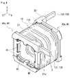
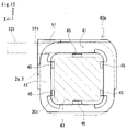
実施形態に係るリアクトル100の概要を説明する。リアクトル100は、図1、図2に示すように、コイル10と磁性コア30と保持部材40とを備える。コイル10は、図3に示すように、本体部110と端末部130とを有する。本実施形態では、端末部130として、第一端末部131と第二端末部132とを有する。保持部材40は、コイル10の端部に配置される。本実施形態では、図4に示すように、保持部材40として、第一保持部材40aと第二保持部材40bとを有する。リアクトル100の特徴の一つは、第一端末部131と第一保持部材40aとが特定の構造を備える点にある。以下、リアクトル100の構成を詳細に説明する。 <Overview of Reactor>
An overview of thereactor 100 according to the embodiment will be described. The reactor 100 includes a coil 10, a magnetic core 30, and a holding member 40, as shown in FIGS. The coil 10 has a body portion 110 and terminal portions 130, as shown in FIG. In this embodiment, the terminal unit 130 has a first terminal unit 131 and a second terminal unit 132 . A holding member 40 is arranged at the end of the coil 10 . In this embodiment, as shown in FIG. 4, the holding member 40 includes a first holding member 40a and a second holding member 40b. One of the features of the reactor 100 is that the first terminal portion 131 and the first holding member 40a have specific structures. The configuration of reactor 100 will be described in detail below.
実施形態に係るリアクトル100の概要を説明する。リアクトル100は、図1、図2に示すように、コイル10と磁性コア30と保持部材40とを備える。コイル10は、図3に示すように、本体部110と端末部130とを有する。本実施形態では、端末部130として、第一端末部131と第二端末部132とを有する。保持部材40は、コイル10の端部に配置される。本実施形態では、図4に示すように、保持部材40として、第一保持部材40aと第二保持部材40bとを有する。リアクトル100の特徴の一つは、第一端末部131と第一保持部材40aとが特定の構造を備える点にある。以下、リアクトル100の構成を詳細に説明する。 <Overview of Reactor>
An overview of the
(コイル)
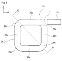
図3、図5を主に参照して、コイル10の概要を説明する。コイル10は、平角線1で構成されたエッジワイズ型のコイルである。図3では、第二端末部132をコイル10の軸方向にフラットワイズ曲げする前であって、図2に示すコイル10の形状とする前の状態を示している。図5は、図3に示すコイル10を第一端部121側からコイル10の軸方向に見た図である。図5では、第二端末部132の図示を省略している。
以下の説明において、端末部130が設けられた側を上とする。コイル10の第一端部121側の端面を正面とし、コイル10の第二端部122側の端面を背面とする。正面から背面に向かう方向から見て右側を右とし、左側を左とする。図中、矢印Xは右方向、矢印Yは軸方向、矢印Zは上方向をそれぞれ示している。 (coil)
An outline of thecoil 10 will be described mainly with reference to FIGS. 3 and 5. FIG. A coil 10 is an edgewise coil made of a rectangular wire 1 . FIG. 3 shows a state before the second terminal portion 132 is bent flatwise in the axial direction of the coil 10 and before the coil 10 is shaped as shown in FIG. FIG. 5 is a view of the coil 10 shown in FIG. 3 as viewed in the axial direction of the coil 10 from the first end portion 121 side. In FIG. 5, illustration of the second terminal portion 132 is omitted.
In the following description, the side on which the terminal unit 130 is provided is taken as the top. The end surface of thecoil 10 on the side of the first end 121 is defined as the front, and the end surface of the coil 10 on the side of the second end 122 is defined as the back. When viewed from the front to back, the right side is right and the left side is left. In the figure, arrow X indicates the right direction, arrow Y indicates the axial direction, and arrow Z indicates the upward direction.
図3、図5を主に参照して、コイル10の概要を説明する。コイル10は、平角線1で構成されたエッジワイズ型のコイルである。図3では、第二端末部132をコイル10の軸方向にフラットワイズ曲げする前であって、図2に示すコイル10の形状とする前の状態を示している。図5は、図3に示すコイル10を第一端部121側からコイル10の軸方向に見た図である。図5では、第二端末部132の図示を省略している。
以下の説明において、端末部130が設けられた側を上とする。コイル10の第一端部121側の端面を正面とし、コイル10の第二端部122側の端面を背面とする。正面から背面に向かう方向から見て右側を右とし、左側を左とする。図中、矢印Xは右方向、矢印Yは軸方向、矢印Zは上方向をそれぞれ示している。 (coil)
An outline of the
In the following description, the side on which the terminal unit 130 is provided is taken as the top. The end surface of the
(平角線)
平角線1は、断面が矩形の巻線である。上記断面とは、平角線1の長手方向に直交する断面である。上記矩形は、図8に示す平角線1のように、一対の短辺と一対の長辺とを有する。平角線1の幅は、向かい合う短辺同士の距離であり、長辺の長さに相当する。平角線1の幅方向は、実質的に矩形の長辺に沿う方向である。平角線1の厚さは、向かい合う長辺同士の距離であり、短辺の長さに相当する。平角線1の厚さ方向は、実質的に矩形の短辺に沿う方向である。平角線1の幅及び厚さは適宜選択できる。平角線1の幅は、例えば3mm以上15mm以下、更に5mm以上12mm以下である。平角線1の厚さは、例えば0.5mm以上5mm以下、更に0.8mm以上3mm以下である。 (flat wire)
Therectangular wire 1 is a wire having a rectangular cross section. The cross section is a cross section perpendicular to the longitudinal direction of the flat wire 1 . The rectangle has a pair of short sides and a pair of long sides like the rectangular wire 1 shown in FIG. The width of the flat wire 1 is the distance between the short sides facing each other and corresponds to the length of the long side. The width direction of the rectangular wire 1 is substantially along the long side of the rectangle. The thickness of the rectangular wire 1 is the distance between the long sides facing each other and corresponds to the length of the short sides. The thickness direction of the flat wire 1 is substantially along the short side of the rectangle. The width and thickness of the rectangular wire 1 can be appropriately selected. The width of the rectangular wire 1 is, for example, 3 mm or more and 15 mm or less, and further 5 mm or more and 12 mm or less. The thickness of the rectangular wire 1 is, for example, 0.5 mm or more and 5 mm or less, and further 0.8 mm or more and 3 mm or less.
平角線1は、断面が矩形の巻線である。上記断面とは、平角線1の長手方向に直交する断面である。上記矩形は、図8に示す平角線1のように、一対の短辺と一対の長辺とを有する。平角線1の幅は、向かい合う短辺同士の距離であり、長辺の長さに相当する。平角線1の幅方向は、実質的に矩形の長辺に沿う方向である。平角線1の厚さは、向かい合う長辺同士の距離であり、短辺の長さに相当する。平角線1の厚さ方向は、実質的に矩形の短辺に沿う方向である。平角線1の幅及び厚さは適宜選択できる。平角線1の幅は、例えば3mm以上15mm以下、更に5mm以上12mm以下である。平角線1の厚さは、例えば0.5mm以上5mm以下、更に0.8mm以上3mm以下である。 (flat wire)
The
(本体部)
本体部110は、図3に示すように、平角線1をエッジワイズ巻きして螺旋状に形成された部分である。本体部110は複数のターン2によって構成される。本体部110は、第一端部121と第二端部122とを含む。第一端部121は、本体部110の軸方向の一方の端部である。第二端部122は、本体部110の軸方向の他方の端部である。 (main body)
As shown in FIG. 3, thebody portion 110 is a portion formed in a spiral shape by edgewise winding the rectangular wire 1 . The body portion 110 is composed of a plurality of turns 2 . Body portion 110 includes a first end portion 121 and a second end portion 122 . The first end portion 121 is one end portion of the body portion 110 in the axial direction. The second end portion 122 is the other end portion of the body portion 110 in the axial direction.
本体部110は、図3に示すように、平角線1をエッジワイズ巻きして螺旋状に形成された部分である。本体部110は複数のターン2によって構成される。本体部110は、第一端部121と第二端部122とを含む。第一端部121は、本体部110の軸方向の一方の端部である。第二端部122は、本体部110の軸方向の他方の端部である。 (main body)
As shown in FIG. 3, the
本体部110の形状は、円筒状でもよいし、角筒状でもよい。円筒状とは、本体部110を軸方向から見た端面の形状が、円形状であるものをいう。円形状には、真円形状のみならず、楕円形状も含む。角筒状とは、上記端面の形状が、多角形状であるものをいう。多角形状は、例えば、三角形状、四角形状、六角形状、八角形状である。四角形状には、矩形状、台形状が含まれる。矩形状には、正方形状が含まれる。本実施形態では、本体部110が角筒状である。本体部110の端面が矩形状である。
The shape of the body part 110 may be cylindrical or rectangular. The term “cylindrical” means that the shape of the end surface of the main body 110 viewed from the axial direction is circular. The circular shape includes not only a true circular shape but also an elliptical shape. The square tubular shape means that the shape of the end face is polygonal. Polygonal shapes are, for example, triangular, quadrangular, hexagonal, and octagonal. A square shape includes a rectangular shape and a trapezoidal shape. A rectangular shape includes a square shape. In this embodiment, the body portion 110 has a rectangular tubular shape. The end face of the body portion 110 is rectangular.
各ターン2の形状は、上述した本体部110の端面の形状と実質的に同じである。ターン2の形状とは、ターン2の軸方向から見た形状である。本実施形態では、図5に示すように、ターン2の形状が矩形状である。ターン2は、平角線1が直線状に配置された4つの直線部20sと、平角線1が屈曲された4つの角部20cとを有する。
The shape of each turn 2 is substantially the same as the shape of the end surface of the body portion 110 described above. The shape of the turn 2 is the shape of the turn 2 viewed from the axial direction. In this embodiment, as shown in FIG. 5, the turn 2 has a rectangular shape. The turn 2 has four straight portions 20s in which the flat wire 1 is linearly arranged and four corner portions 20c in which the flat wire 1 is bent.
ターン2の数は適宜選択できる。ターン2の数は、例えば10ターン以上60ターン以下、更に20ターン以上50ターン以下である。
The number of turns 2 can be selected as appropriate. The number of turns 2 is, for example, 10 turns or more and 60 turns or less, and further 20 turns or more and 50 turns or less.
(端末部)
端末部130は、図3に示すように、本体部110の軸方向における端部120から平角線1が引き出された部分である。端末部130は、本体部110の輪郭から外側に突出する。端末部130のうち、第一端末部131は、第一端部121から引き出されている。第二端末部132は、第二端部122から引き出されている。第一端末部131及び第二端末部132には、図12に示すように、バスバー61,62が接続される。 (Terminal part)
As shown in FIG. 3 , the terminal portion 130 is a portion where therectangular wire 1 is pulled out from the end portion 120 in the axial direction of the main body portion 110 . Terminal portion 130 protrudes outward from the contour of body portion 110 . A first terminal portion 131 of the terminal portion 130 is pulled out from the first end portion 121 . The second terminal portion 132 is pulled out from the second end portion 122 . Bus bars 61 and 62 are connected to the first terminal portion 131 and the second terminal portion 132, as shown in FIG.
端末部130は、図3に示すように、本体部110の軸方向における端部120から平角線1が引き出された部分である。端末部130は、本体部110の輪郭から外側に突出する。端末部130のうち、第一端末部131は、第一端部121から引き出されている。第二端末部132は、第二端部122から引き出されている。第一端末部131及び第二端末部132には、図12に示すように、バスバー61,62が接続される。 (Terminal part)
As shown in FIG. 3 , the terminal portion 130 is a portion where the
〈第一端末部〉
第一端末部131は、図3に示すように、本体部110の第一端部121側の端面に沿う方向に引き出されている。本体部110の端面に沿う方向は、本体部110の軸方向と交差する。第一端末部131は、本体部110を構成する複数のターン2のうち、第一端部121側に位置する第一端部ターン2aにつながっている。第一端部ターン2aは、第一端部121側の端面を構成する。本実施形態では、図5に示すように、第一端末部131は第一端部ターン2aにおける上側の直線部20sの延長方向に沿って引き出されている。第一端末部131は直線部20sに連続して右方向に延びている。本実施形態とは異なり、第一端末部131を本体部110の軸方向と直交する方向にエッジワイズ曲げして、第一端末部131が直線部20sの延長方向と直交するように引き出されていてもよい。 <First terminal part>
As shown in FIG. 3 , the firstterminal portion 131 is pulled out in a direction along the end surface of the main body portion 110 on the first end portion 121 side. A direction along the end surface of the body portion 110 intersects with the axial direction of the body portion 110 . The first terminal portion 131 is connected to the first end portion turn 2 a located on the first end portion 121 side among the plurality of turns 2 forming the body portion 110 . The first end turn 2a constitutes an end face on the first end 121 side. In this embodiment, as shown in FIG. 5, the first end portion 131 is drawn out along the extending direction of the upper straight portion 20s of the first end turn 2a. The first terminal portion 131 extends rightward continuously from the straight portion 20s. Unlike the present embodiment, the first terminal portion 131 is bent edgewise in a direction orthogonal to the axial direction of the main body portion 110, and the first terminal portion 131 is pulled out so as to be orthogonal to the extending direction of the straight portion 20s. may
第一端末部131は、図3に示すように、本体部110の第一端部121側の端面に沿う方向に引き出されている。本体部110の端面に沿う方向は、本体部110の軸方向と交差する。第一端末部131は、本体部110を構成する複数のターン2のうち、第一端部121側に位置する第一端部ターン2aにつながっている。第一端部ターン2aは、第一端部121側の端面を構成する。本実施形態では、図5に示すように、第一端末部131は第一端部ターン2aにおける上側の直線部20sの延長方向に沿って引き出されている。第一端末部131は直線部20sに連続して右方向に延びている。本実施形態とは異なり、第一端末部131を本体部110の軸方向と直交する方向にエッジワイズ曲げして、第一端末部131が直線部20sの延長方向と直交するように引き出されていてもよい。 <First terminal part>
As shown in FIG. 3 , the first
〈第二端末部〉
第二端末部132は、図3に示すように、本体部110を構成する複数のターン2のうち、第二端部122側に位置する第二端部ターン2bにつながっている。第二端部ターン2bは、第二端部122側の端面を構成する。本実施形態では、第二端末部132は、第一端末部131とは異なり、図2に示すようにリアクトル100を組み立てる前に、本体部110の軸方向に沿う方向に引き出される。本実施形態とは異なり、第二端末部132は、第一端末部131と同じように、本体部110の第二端部122側の端面に沿う方向に引き出されてもよい。この場合、第二端末部132は、図3に示すように、第二端部ターン2bにおける上側の直線部に連続して左方向に引き出される。 <Second terminal part>
As shown in FIG. 3 , the secondterminal portion 132 is connected to the second end portion turn 2 b positioned on the second end portion 122 side among the plurality of turns 2 forming the body portion 110 . The second end turn 2b constitutes the end face on the second end 122 side. In this embodiment, unlike the first terminal portion 131, the second terminal portion 132 is pulled out in the axial direction of the main body portion 110 before the reactor 100 is assembled as shown in FIG. Unlike the present embodiment, the second terminal portion 132 may be pulled out in a direction along the end surface of the body portion 110 on the second end portion 122 side, like the first terminal portion 131 . In this case, as shown in FIG. 3, the second end portion 132 is pulled out leftward continuously from the upper straight portion of the second end turn 2b.
第二端末部132は、図3に示すように、本体部110を構成する複数のターン2のうち、第二端部122側に位置する第二端部ターン2bにつながっている。第二端部ターン2bは、第二端部122側の端面を構成する。本実施形態では、第二端末部132は、第一端末部131とは異なり、図2に示すようにリアクトル100を組み立てる前に、本体部110の軸方向に沿う方向に引き出される。本実施形態とは異なり、第二端末部132は、第一端末部131と同じように、本体部110の第二端部122側の端面に沿う方向に引き出されてもよい。この場合、第二端末部132は、図3に示すように、第二端部ターン2bにおける上側の直線部に連続して左方向に引き出される。 <Second terminal part>
As shown in FIG. 3 , the second
《コイルの詳細》
図6、図7を参照して、本実施形態におけるコイル10の構成を詳しく説明する。図6は、図5のVI-VI断面における切断面のみを示している。図6では、切断面より奥に見える構成は省略している。図5のVI-VI線は、ターン2の対角線である。コイル10の特徴の一つは、本体部110において、ターン2を形成する平角線1が特定の形状を有している点にある。図6、図7では、コイル10の構成や保持部材40構成を簡略化して模式的に示している。図7は、保持部材40が組み付けられていないコイル10のみの状態を示している。保持部材40については後述する。 《Details of the coil》
The configuration of thecoil 10 in this embodiment will be described in detail with reference to FIGS. 6 and 7. FIG. FIG. 6 shows only a cross section along the line VI-VI of FIG. In FIG. 6, the configuration seen behind the cut surface is omitted. The line VI-VI in FIG. 5 is the diagonal of turn 2 . One of the features of the coil 10 is that the rectangular wire 1 forming the turns 2 in the main body 110 has a specific shape. 6 and 7 schematically show the configuration of the coil 10 and the configuration of the holding member 40 in a simplified manner. FIG. 7 shows the state of only the coil 10 without the holding member 40 assembled. The holding member 40 will be described later.
図6、図7を参照して、本実施形態におけるコイル10の構成を詳しく説明する。図6は、図5のVI-VI断面における切断面のみを示している。図6では、切断面より奥に見える構成は省略している。図5のVI-VI線は、ターン2の対角線である。コイル10の特徴の一つは、本体部110において、ターン2を形成する平角線1が特定の形状を有している点にある。図6、図7では、コイル10の構成や保持部材40構成を簡略化して模式的に示している。図7は、保持部材40が組み付けられていないコイル10のみの状態を示している。保持部材40については後述する。 《Details of the coil》
The configuration of the
図6に示すように、本体部110を構成する複数のターン2の各々は、内周部1iと外周部1eとを有する。内周部1iは、平角線1におけるターン2の内周側を構成する。外周部1eは、平角線1におけるターン2の外周側を構成する。外周部1eは、内周部1iに対して本体部110の軸方向の第一の方向に向かって傾くように曲げられている。換言すれば、ターン2を形成する平角線1が平角線1の幅方向の途中で屈曲されている。内周部1iと外周部1eとは屈曲部1bを介してつながっている。内周部1iは、平角線1における屈曲部1bよりもターン2の内周側に位置する部分である。外周部1eは、平角線1における屈曲部1bよりもターン2の外周側に位置する部分である。本実施形態では、図5に示す角部20c及び直線部20sのいずれにおいても、ターン2における平角線1が幅方向の途中で屈曲されている。
As shown in FIG. 6, each of the plurality of turns 2 forming the body portion 110 has an inner peripheral portion 1i and an outer peripheral portion 1e. The inner peripheral portion 1 i constitutes the inner peripheral side of the turn 2 in the rectangular wire 1 . The outer peripheral portion 1 e constitutes the outer peripheral side of the turn 2 in the rectangular wire 1 . The outer peripheral portion 1e is bent toward the first axial direction of the body portion 110 with respect to the inner peripheral portion 1i. In other words, the flat wire 1 forming the turn 2 is bent in the middle of the width direction of the flat wire 1 . The inner peripheral portion 1i and the outer peripheral portion 1e are connected via the bent portion 1b. The inner peripheral portion 1i is a portion of the flat wire 1 positioned closer to the inner peripheral side of the turn 2 than the bent portion 1b. The outer peripheral portion 1e is a portion of the flat wire 1 positioned closer to the outer peripheral side of the turn 2 than the bent portion 1b. In this embodiment, the rectangular wire 1 in the turn 2 is bent halfway in the width direction at both the corner portion 20c and the straight portion 20s shown in FIG.
内周部1iは、本体部110の軸方向に沿った断面を見たとき、ターン2の内周側から外周側に向かって実質的に径方向に沿って延びている。つまり、内周部1iは、ターン2の径方向と実質的に平行に延びている。内周部1iが平角線1の巻きピッチによって径方向からずれている分については、径方向に沿っているとみなす。
The inner peripheral portion 1i extends substantially radially from the inner peripheral side of the turn 2 toward the outer peripheral side when viewed in cross section along the axial direction of the main body portion 110 . That is, the inner peripheral portion 1i extends substantially parallel to the radial direction of the turn 2. As shown in FIG. The deviation of the inner peripheral portion 1i from the radial direction due to the winding pitch of the rectangular wire 1 is considered to be along the radial direction.
上記第一の方向は、本体部110の軸方向の他方の端部から一方の端部に向かう方向である。即ち、第一の方向は、第二端部122から第一端部121に向かう方向である。第一の方向は、背面から正面に向かう方向と一致する。図6では、第一の方向は上から下に向かう方向である。つまり、外周部1eは、内周部1iに対して下方に向かって傾斜している。
The first direction is the direction from the other axial end of the body portion 110 to the one axial end. That is, the first direction is the direction from the second end 122 toward the first end 121 . The first direction corresponds to the direction from the back to the front. In FIG. 6, the first direction is from top to bottom. That is, the outer peripheral portion 1e is inclined downward with respect to the inner peripheral portion 1i.
平角線1の幅方向における内周部1iの長さは、例えば、平角線1の幅の30%以上75%以下、更に40%以上70%以下である。平角線1の幅方向における外周部1eの長さは、例えば、平角線1の幅の25%以上70%以下、更に30%以上60%以下である。
The length of the inner peripheral portion 1i in the width direction of the flat wire 1 is, for example, 30% or more and 75% or less, further 40% or more and 70% or less of the width of the flat wire 1. The length of the outer peripheral portion 1e in the width direction of the flat wire 1 is, for example, 25% or more and 70% or less of the width of the flat wire 1, and further 30% or more and 60% or less.
〈変位量〉
内周部1iと外周部1eとの本体部110の軸方向の変位量1dは、例えば0.1mm以上0.5mm以下、更に0.2mm以上0.4mm以下である。変位量1dは、ターン2における角部での変位量である。ターン2における直線部での変位量は、角部での変位量よりも小さくてもよい。上記角部とは、図5に示す角部20cである。上記直線部とは、図5に示す直線部20sである。 <Displacement>
Adisplacement amount 1d in the axial direction of the body portion 110 between the inner peripheral portion 1i and the outer peripheral portion 1e is, for example, 0.1 mm or more and 0.5 mm or less, and further 0.2 mm or more and 0.4 mm or less. The displacement amount 1d is the displacement amount at the corner of the turn 2 . The amount of displacement in the straight portion of turn 2 may be smaller than the amount of displacement in the corner portion. The corner portion is the corner portion 20c shown in FIG. The linear portion is the linear portion 20s shown in FIG.
内周部1iと外周部1eとの本体部110の軸方向の変位量1dは、例えば0.1mm以上0.5mm以下、更に0.2mm以上0.4mm以下である。変位量1dは、ターン2における角部での変位量である。ターン2における直線部での変位量は、角部での変位量よりも小さくてもよい。上記角部とは、図5に示す角部20cである。上記直線部とは、図5に示す直線部20sである。 <Displacement>
A
複数のターン2において、全ての変位量1dが同じであってもよい。複数のターン2のうち、一部のターン2における変位量1dが、残りのターン2の少なくとも一部における変位量1dと異なってもよい。
All the displacement amounts 1d may be the same in a plurality of turns 2. Of the plurality of turns 2 , the displacement amount 1 d of some turns 2 may differ from the displacement amount 1 d of at least some of the remaining turns 2 .
変位量1dは、例えば、レーザ距離計を用いて、次のようにして測定することができる。コイル10を、本体部110の軸方向が垂直となるように水平な台に置く。第一端部121が下、第二端部122が上になるようにコイル10を配置する。コイル10の上方の基準位置から、内周部1iの上面と側面との交点までの距離を測定する。この距離を第一の距離とする。内周部1iの側面は、ターン2の内周面であり、平角線1の断面における矩形の一方の短辺に対応する面である。上記基準位置から外周部1eの上面と側面との交点までの距離を測定する。この距離を第二の距離とする。外周部1eの側面は、ターン2の外周面であり、平角線1の断面における矩形のもう一方の短辺に対応する面である。第一の距離と第二の距離との差を変位量1dとする。そして、ターン2の全ての角部20cにおける変位量1dを測定する。本実施形態であれば、図5に示す4つの角部20cにおけるそれぞれの変位量1dを測定する。測定した全ての角部20cでの変位量1dの平均値をそのターン2における変位量1dとする。
The displacement amount 1d can be measured as follows using, for example, a laser rangefinder. The coil 10 is placed on a horizontal table so that the axial direction of the main body 110 is vertical. The coil 10 is arranged so that the first end portion 121 faces downward and the second end portion 122 faces upward. The distance from the reference position above the coil 10 to the intersection of the upper surface and the side surface of the inner peripheral portion 1i is measured. Let this distance be the first distance. The side surface of the inner peripheral portion 1i is the inner peripheral surface of the turn 2 and is a surface corresponding to one short side of the rectangle in the cross section of the rectangular wire 1 . The distance from the reference position to the intersection of the upper surface and the side surface of the outer peripheral portion 1e is measured. Let this distance be the second distance. The side surface of the outer peripheral portion 1e is the outer peripheral surface of the turn 2 and corresponds to the other short side of the rectangle in the cross section of the rectangular wire 1. As shown in FIG. The difference between the first distance and the second distance is defined as displacement 1d. Then, the displacement 1d at all the corners 20c of the turn 2 is measured. In this embodiment, the displacement 1d of each of the four corners 20c shown in FIG. 5 is measured. The average value of the measured displacement amounts 1d at all the corner portions 20c is taken as the displacement amount 1d at the turn 2. FIG.
本実施形態では、図6を参照して説明したように、本体部110において、ターン2を形成する平角線1が幅方向の途中で屈曲されている。これにより、図7に示すように、第一端部121において第一端末部131が本体部110の軸方向の第一の方向に開いた状態になっている。具体的には、第一端末部131につながる第一端部ターン2aが、第一端部ターン2aに隣り合うターン2から離れている。このように、第一端末部131が第一の方向に開く理由については、後述するコイルの製造方法で説明する。
In the present embodiment, as described with reference to FIG. 6, in the body portion 110, the rectangular wire 1 forming the turn 2 is bent midway in the width direction. As a result, as shown in FIG. 7 , the first end portion 131 of the first end portion 121 is opened in the first axial direction of the body portion 110 . Specifically, the first end turn 2a connected to the first terminal portion 131 is separated from the turn 2 adjacent to the first end turn 2a. The reason why the first terminal portion 131 opens in the first direction in this manner will be described later in the coil manufacturing method.
更に、本実施形態では、図6に示すように、ターン2を形成する平角線1が幅方向の途中で屈曲されていることで、ターン2間の隙間2gを小さくすることができる。隙間2gが小さくなる理由については、後述するコイルの製造方法で説明する。
Furthermore, in this embodiment, as shown in FIG. 6, the rectangular wire 1 forming the turns 2 is bent midway in the width direction, so that the gap 2g between the turns 2 can be reduced. The reason why the gap 2g becomes smaller will be explained later in the coil manufacturing method.
隙間2gは、例えば0.076mm以下、更に0.06mm以下、0.05mm以下である。隙間2gが小さいほど本体部110の長さが短くなるので、下限は設けない。即ち下限はゼロである。
The gap 2g is, for example, 0.076 mm or less, further 0.06 mm or less, or 0.05 mm or less. The smaller the gap 2g, the shorter the length of the main body 110, so there is no lower limit. That is, the lower bound is zero.
隙間2gは、第一端部ターン2aを除く全てのターン2間の隙間2gの平均値として求めることができる。隙間2gは、[(L1-n1×t)/(n1-1)]として求められる。L1は、第一端部ターン2aを含まない本体部110の長さ(mm)である。n1は、第一端部ターン2aを除くターン2の数である。tは、平角線1の厚さ(mm)である。
The gap 2g can be obtained as an average value of the gaps 2g between all the turns 2 except for the first end turn 2a. The gap 2g is obtained as [(L 1 −n 1 ×t)/(n 1 −1)]. L1 is the length (mm) of the body portion 110 not including the first end turn 2a. n1 is the number of turns 2 excluding the first end turn 2a. t is the thickness (mm) of the rectangular wire 1;
本体部110の長さL1は、次のように測定する。本体部110の外周面の周方向の任意の位置に本体部110の軸方向と平行な直線を採る。この直線は、ターン2の外周面に接する仮想の直線である。直線上のターン2のうち、第一端部ターン2aを除いて本体部110の両端に位置するターン2間の距離を求める。この距離を長さL1とする。本体部110の長さL1は、本体部110の軸方向が水平になるようにコイル10を水平な台に置いて測定するとよい。測定は、本体部110に対して荷重をかけていない状態で行う。ターン2の数n1は、上記直線と交差するターン2のうち、第一端部ターン2aを引いた数とする。(n1-1)は、第一端部ターン2aを含まないターン2間の隙間2gの数を表している。
The length L1 of the body portion 110 is measured as follows. A straight line parallel to the axial direction of the body portion 110 is drawn at any position in the circumferential direction of the outer peripheral surface of the body portion 110 . This straight line is an imaginary straight line in contact with the outer peripheral surface of turn 2 . Among the turns 2 on the straight line, the distance between the turns 2 located at both ends of the main body 110 except for the first end turn 2a is obtained. Let this distance be the length L1. The length L1 of the main body 110 may be measured by placing the coil 10 on a horizontal table so that the axial direction of the main body 110 is horizontal. The measurement is performed with no load applied to the main body 110 . The number n1 of turns 2 is the number of turns 2 intersecting the straight line minus the first end turns 2a. (n 1 -1) represents the number of gaps 2g between turns 2 that do not include the first end turn 2a.
(コイルの製造方法)
図8から図12を主に参照して、上述したコイル10の製造方法について説明する。コイル10は巻線機を使用して製造できる。巻線機には、公知の巻線機を利用できる。 (Coil manufacturing method)
Mainly referring to FIGS. 8 to 12, a method for manufacturing thecoil 10 described above will be described. Coil 10 can be manufactured using a winding machine. A known winding machine can be used as the winding machine.
図8から図12を主に参照して、上述したコイル10の製造方法について説明する。コイル10は巻線機を使用して製造できる。巻線機には、公知の巻線機を利用できる。 (Coil manufacturing method)
Mainly referring to FIGS. 8 to 12, a method for manufacturing the
(巻線機)
巻線機は、図8に示す曲げ加工部800と、図示しない送り機構とを備える。曲げ加工部800は、平角線1をエッジワイズ曲げ加工する。送り機構は、平角線1を送り出す。曲げ加工部800は、巻線機の主要な部分の一つである。 (winding machine)
The winding machine includes abending section 800 shown in FIG. 8 and a feed mechanism (not shown). The bending section 800 bends the rectangular wire 1 edgewise. The feeding mechanism feeds out the rectangular wire 1. - 特許庁The bending section 800 is one of the main parts of the winding machine.
巻線機は、図8に示す曲げ加工部800と、図示しない送り機構とを備える。曲げ加工部800は、平角線1をエッジワイズ曲げ加工する。送り機構は、平角線1を送り出す。曲げ加工部800は、巻線機の主要な部分の一つである。 (winding machine)
The winding machine includes a
(曲げ加工部)
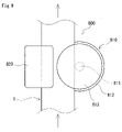
曲げ加工部800は、図8、図9に示すように、保持部810とガイド部820とを有する。保持部810は、平角線1の内周部1iを保持する。平角線1の内周部1iは、平角線1をエッジワイズ曲げする際に、平角線1における曲げの内周側に位置する部分である。ガイド部820は、平角線1の外周部1eを保持する。平角線1の外周部1eは、平角線1における曲げの外周側に位置する部分である。 (bending part)
The bendingportion 800 has a holding portion 810 and a guide portion 820, as shown in FIGS. The holding portion 810 holds the inner peripheral portion 1 i of the rectangular wire 1 . The inner peripheral portion 1i of the flat wire 1 is a portion located on the inner peripheral side of the bending of the flat wire 1 when the flat wire 1 is edgewise bent. The guide portion 820 holds the outer peripheral portion 1 e of the rectangular wire 1 . The outer peripheral portion 1e of the flat wire 1 is a portion of the flat wire 1 located on the outer peripheral side of the bend.
曲げ加工部800は、図8、図9に示すように、保持部810とガイド部820とを有する。保持部810は、平角線1の内周部1iを保持する。平角線1の内周部1iは、平角線1をエッジワイズ曲げする際に、平角線1における曲げの内周側に位置する部分である。ガイド部820は、平角線1の外周部1eを保持する。平角線1の外周部1eは、平角線1における曲げの外周側に位置する部分である。 (bending part)
The bending
〈保持部〉
保持部810は、シャフト811と、シャフト811を支持する支持体812とを有する。シャフト811は、平角線1における内周部1iの側面と接触する円柱状の部材である。内周部1iの側面は、平角線1の断面における矩形の一方の短辺に対応する面である。支持体812は円筒状である。シャフト811は、支持体812の中心を貫通する。シャフト811は、支持体812に対して、シャフト811の軸方向にスライド可能である。シャフト811の先端は、支持体812の端面から突出する。シャフト811の先端には、円板状のフランジ813を有する。支持体812とフランジ813とは離間して配置されている。 <Holding part>
The holdingportion 810 has a shaft 811 and a support 812 that supports the shaft 811 . The shaft 811 is a cylindrical member that contacts the side surface of the inner peripheral portion 1 i of the rectangular wire 1 . A side surface of the inner peripheral portion 1i is a surface corresponding to one short side of the rectangle in the cross section of the rectangular wire 1. As shown in FIG. Support 812 is cylindrical. Shaft 811 passes through the center of support 812 . The shaft 811 is slidable in the axial direction of the shaft 811 with respect to the support 812 . The tip of the shaft 811 protrudes from the end surface of the support 812 . A disc-shaped flange 813 is provided at the tip of the shaft 811 . The support 812 and the flange 813 are spaced apart.
保持部810は、シャフト811と、シャフト811を支持する支持体812とを有する。シャフト811は、平角線1における内周部1iの側面と接触する円柱状の部材である。内周部1iの側面は、平角線1の断面における矩形の一方の短辺に対応する面である。支持体812は円筒状である。シャフト811は、支持体812の中心を貫通する。シャフト811は、支持体812に対して、シャフト811の軸方向にスライド可能である。シャフト811の先端は、支持体812の端面から突出する。シャフト811の先端には、円板状のフランジ813を有する。支持体812とフランジ813とは離間して配置されている。 <Holding part>
The holding
保持部810は、支持体812の端面によって構成される第一面812fと、支持体812と向かい合うフランジ813の面によって構成される第二面813fとを有する。第一面812fと第二面813fとは、平角線1の内周部1iを厚さ方向に挟むように向かい合って配置される。第一面812fと第二面813fとの間に平角線1の内周部1iが通されて保持される。第一面812fと内周部1iとの間、及び第二面813fと内周部1iとの間は、平角線1を送り出した際に平角線1が通過できるように、若干のクリアランスが設けられている。
The holding portion 810 has a first surface 812f constituted by the end surface of the support 812 and a second surface 813f constituted by the surface of the flange 813 facing the support 812. The first surface 812f and the second surface 813f are arranged to face each other so as to sandwich the inner peripheral portion 1i of the rectangular wire 1 in the thickness direction. The inner peripheral portion 1i of the rectangular wire 1 is passed between the first surface 812f and the second surface 813f and held. A slight clearance is provided between the first surface 812f and the inner peripheral portion 1i and between the second surface 813f and the inner peripheral portion 1i so that the rectangular wire 1 can pass through when the rectangular wire 1 is fed out. It is
〈ガイド部〉
ガイド部820は、シャフト811の中心軸を回転中心にして回動可能である。ガイド部820は、平角線1の内周部1iを厚さ方向に挟むようにガイド溝821が形成されている。このガイド溝821に、平角線1の外周部1eが通されて保持される。ガイド溝821の幅は、平角線1を送り出した際に平角線1が通過できるように、平角線1の外周部1eの厚さよりも若干大きい。 <Guide part>
Theguide portion 820 is rotatable around the central axis of the shaft 811 . A guide groove 821 is formed in the guide portion 820 so as to sandwich the inner peripheral portion 1i of the rectangular wire 1 in the thickness direction. The outer peripheral portion 1e of the rectangular wire 1 is passed through the guide groove 821 and held. The width of the guide groove 821 is slightly larger than the thickness of the outer peripheral portion 1e of the rectangular wire 1 so that the rectangular wire 1 can pass through when the rectangular wire 1 is fed.
ガイド部820は、シャフト811の中心軸を回転中心にして回動可能である。ガイド部820は、平角線1の内周部1iを厚さ方向に挟むようにガイド溝821が形成されている。このガイド溝821に、平角線1の外周部1eが通されて保持される。ガイド溝821の幅は、平角線1を送り出した際に平角線1が通過できるように、平角線1の外周部1eの厚さよりも若干大きい。 <Guide part>
The
本実施形態では、保持部810に対してガイド部820がシャフト811の軸方向にスライド可能である。ガイド部820の位置は、例えば図示しない駆動装置によって制御される。駆動装置は、例えばサーボモータである。
In this embodiment, the guide portion 820 can slide in the axial direction of the shaft 811 with respect to the holding portion 810 . The position of the guide portion 820 is controlled by, for example, a driving device (not shown). The drive device is, for example, a servomotor.
図9、図10を参照して、平角線1をエッジワイズ曲げする際の曲げ加工部800の動作を説明する。ここでは、図3、図5に示す四角筒状のコイル10を形成する場合を例に挙げて説明する。図9、図10は、曲げ加工部800をフランジ813側、即ち図8の下側からシャフト811の軸方向に見ている。図9に示すように、図示しない送り機構によって平角線1を直線状に送り出す。図9中の矢印は、平角線1の送り方向を示す。次に、図10に示すように、ガイド部820がシャフト811の中心軸を回転中心にして回動する。内周部1iの側面がシャフト811の外周面に押し付けられて、平角線1がシャフト811の外周面に沿って曲がる。これにより、平角線1がエッジワイズ曲げされた角部が形成される。本実施形態では、ガイド部820が90°回動することによって、平角線1を90°曲げる。この動作を繰り返すことによって、1つのターン2を形成する。平角線1の送り出しとエッジワイズ曲げ加工とを4回繰り返すことにより、矩形状のターン2を形成する。そして、ターン2の形成を複数回繰り返し行うことにより、複数のターン2を形成することで、コイル10が形成される。
The operation of the bending section 800 when edgewise bending the rectangular wire 1 will be described with reference to FIGS. Here, the case of forming the rectangular cylindrical coil 10 shown in FIGS. 3 and 5 will be described as an example. 9 and 10 are views of the bent portion 800 in the axial direction of the shaft 811 from the flange 813 side, that is, from the lower side of FIG. As shown in FIG. 9, the rectangular wire 1 is linearly fed by a feeding mechanism (not shown). Arrows in FIG. 9 indicate the feeding direction of the rectangular wire 1 . Next, as shown in FIG. 10, the guide portion 820 rotates about the central axis of the shaft 811 . The side surface of the inner peripheral portion 1 i is pressed against the outer peripheral surface of the shaft 811 , and the rectangular wire 1 is bent along the outer peripheral surface of the shaft 811 . As a result, corners are formed by bending the rectangular wire 1 edgewise. In this embodiment, the rectangular wire 1 is bent by 90 degrees by rotating the guide portion 820 by 90 degrees. By repeating this operation, one turn 2 is formed. Rectangular turns 2 are formed by repeating feeding out the rectangular wire 1 and edgewise bending four times. By repeating the formation of the turns 2 a plurality of times, the coil 10 is formed by forming a plurality of turns 2 .
平角線1の送り出し時は、図8に示すように、支持体812とフランジ813とは、平角線1の内周部1iとの間に隙間が形成されるような間隔に保持される。平角線1のエッジワイズ曲げ加工時は、支持体812とフランジ813とは、平角線1の内周部1iを上下から挟むような間隔に閉じられる。平角線1をエッジワイズ曲げしたとき、曲げの内周側が厚さ方向に膨らむように変形して、内周部1iが厚くなる。支持体812とフランジ813とで平角線1の内周部1iを平角線1の厚さ方向から挟むことで、エッジワイズ曲げ加工時に平角線1の内周部1iが厚くなることを抑制できる。
When the flat wire 1 is fed, as shown in FIG. 8, the support 812 and the flange 813 are held at a distance such that a gap is formed between the flat wire 1 and the inner peripheral portion 1i of the flat wire 1. When the flat wire 1 is edgewise bent, the support 812 and the flange 813 are closed so as to sandwich the inner peripheral portion 1i of the flat wire 1 from above and below. When the rectangular wire 1 is bent edgewise, the inner peripheral side of the bending deforms so as to swell in the thickness direction, and the inner peripheral portion 1i becomes thicker. By sandwiching the inner peripheral portion 1i of the flat wire 1 between the support 812 and the flange 813 in the thickness direction of the flat wire 1, it is possible to suppress the inner peripheral portion 1i of the flat wire 1 from becoming thick during edgewise bending.
一般に、巻線機を使用してコイルを作製する場合、保持部810とガイド部820との位置関係は、図8に示すように、シャフト811の軸方向において、平角線1の内周部1iを保持する位置と、平角線1の外周部1eを保持する位置とが略一致するように設定されている。つまり、平角線1における内周部1iと外周部1eとが平坦になるように、保持部810に対してガイド部820が位置する。このときのガイド部820の位置をガイド部820の基準位置とする。基準位置とは、保持部810が平角線1の内周部1iを保持したときの第一面812fと第二面813fとの間の中心線と、ガイド部820のガイド溝821の幅の中心線とが揃う位置である。
In general, when a coil is manufactured using a winding machine, the positional relationship between the holding portion 810 and the guide portion 820 is such that the inner peripheral portion 1i of the rectangular wire 1 in the axial direction of the shaft 811 is and the position for holding the outer peripheral portion 1e of the rectangular wire 1 are set so as to substantially coincide with each other. That is, the guide portion 820 is positioned with respect to the holding portion 810 so that the inner peripheral portion 1i and the outer peripheral portion 1e of the rectangular wire 1 are flat. The position of the guide portion 820 at this time is the reference position of the guide portion 820 . The reference position is the center line between the first surface 812f and the second surface 813f when the holding portion 810 holds the inner peripheral portion 1i of the rectangular wire 1, and the center of the width of the guide groove 821 of the guide portion 820. This is the position where the line is aligned.
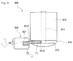
上述したコイル10の製造方法の詳細を説明する。コイル10の製造方法は、上述した曲げ加工部800を備える巻線機を使用する。コイル10の製造方法は、平角線1を螺旋状にエッジワイズ巻きして複数のターン2を形成する工程を備える。コイル10の製造方法の特徴の一つは、図11に示すように保持部810に対してガイド部820を特定の方向に変位させた状態で、ターン2を形成する点にある。以下の説明では、図5から図7を適宜参照するものとする。
The details of the manufacturing method of the coil 10 described above will be described. A method for manufacturing the coil 10 uses a winding machine having the bending portion 800 described above. A method of manufacturing the coil 10 includes a step of spirally winding a rectangular wire 1 edgewise to form a plurality of turns 2 . One of the features of the method of manufacturing the coil 10 is that the turn 2 is formed while the guide portion 820 is displaced in a specific direction with respect to the holding portion 810 as shown in FIG. In the following description, FIGS. 5 to 7 will be referred to as appropriate.
本実施形態では、本体部110の第一端部121側から巻き始める。つまり、初めに、第一端部ターン2aを形成する。第一端部ターン2aを形成するときは、図5、図7に示す第一端末部131となる長さ分、平角線1を送り出す。このときの平角線1の送り量は、第一端末部131と1つの直線部20sとを含む長さである。平角線1を直線状に送り出した後、平角線1をエッジワイズ曲げして角部20cを形成する。その後、図9、図10を参照して説明したように、平角線1の送り出しとエッジワイズ曲げ加工とを繰り返すことにより、第一端部ターン2aを形成する。次いで、この動作を繰り返して、ターン2を連続して形成する。所定の数のターン2を形成することにより、本体部110を形成する。最終のターン2となる第二端部ターン2bを形成した後、第二端末部132となる長さ分、平角線1を送り出す。
In this embodiment, the winding is started from the first end portion 121 side of the main body portion 110 . That is, first, the first end turn 2a is formed. When forming the first end turn 2a, the flat wire 1 is sent out by the length corresponding to the first end portion 131 shown in FIGS. The feeding amount of the flat wire 1 at this time is the length including the first terminal portion 131 and one straight portion 20s. After the rectangular wire 1 is sent out in a straight line, the rectangular wire 1 is bent edgewise to form the corner portion 20c. After that, as described with reference to FIGS. 9 and 10, the flat wire 1 is repeatedly fed out and edgewise bent to form the first end turn 2a. This operation is then repeated to form turns 2 in succession. A body portion 110 is formed by forming a predetermined number of turns 2 . After forming the second end turn 2 b that will be the final turn 2 , the rectangular wire 1 is sent out by the length that will become the second end portion 132 .
ターン2を形成する工程は、図11に示すように、保持部810に対してガイド部820をシャフト811の軸方向の第一の方向に変位させた状態で行う。具体的には、保持部810を基準としてガイド部820を下方にスライドさせることにより、保持部810に対してガイド部820を下方に変位させる。つまり、第一の方向は、図11の上から下に向かう方向である。保持部810に対してガイド部820を下方に変位させることで、平角線1における外周部1eが内周部1iに対して下方に傾斜するように平角線1を屈曲させることができる。この状態でターン2を形成することにより、図6に示すように、外周部1eが内周部1iに対して下方に向かって傾斜したターン2を形成できる。
As shown in FIG. 11, the step of forming the turn 2 is performed with the guide portion 820 displaced relative to the holding portion 810 in the first axial direction of the shaft 811 . Specifically, by sliding the guide portion 820 downward with respect to the holding portion 810 , the guide portion 820 is displaced downward with respect to the holding portion 810 . That is, the first direction is the direction from top to bottom in FIG. By displacing the guide portion 820 downward with respect to the holding portion 810, the rectangular wire 1 can be bent so that the outer peripheral portion 1e of the rectangular wire 1 is inclined downward with respect to the inner peripheral portion 1i. By forming the turn 2 in this state, as shown in FIG. 6, it is possible to form the turn 2 in which the outer peripheral portion 1e is inclined downward with respect to the inner peripheral portion 1i.
ターン2を形成する間は、ガイド部820を変位させた状態を維持する。つまり、保持部810とガイド部820との位置関係は維持される。エッジワイズ曲げ加工時は支持体812とフランジ813とで平角線1の内周部1iを挟むため、ターン2の角部20cでは、平角線1が折り曲げられる。一方、平角線1を送り出すときは、支持体812とフランジ813とは、平角線1の内周部1iとの間に隙間が形成されるような間隔で保持される。そのため、ターン2の直線部20sでは、角部20cに比べて平角線1を折り曲げる力が加わり難く、平角線1の曲げが小さくなる場合があると考えられる。本実施形態では、第一端末部131となる長さ分、及び第二端末部132となる長さ分、平角線1を送り出すときもガイド部820を変位させた状態を維持する。
The displaced state of the guide portion 820 is maintained while the turn 2 is being formed. That is, the positional relationship between the holding portion 810 and the guide portion 820 is maintained. Since the support 812 and the flange 813 sandwich the inner peripheral portion 1i of the rectangular wire 1 during edgewise bending, the rectangular wire 1 is bent at the corner portion 20c of the turn 2. FIG. On the other hand, when the flat wire 1 is sent out, the support 812 and the flange 813 are held at such a distance that a gap is formed between them and the inner peripheral portion 1i of the flat wire 1 . Therefore, in the straight portion 20s of the turn 2, a force for bending the flat wire 1 is less likely to be applied than in the corner portion 20c, and the bending of the flat wire 1 may be small. In the present embodiment, the guide portion 820 is kept displaced by the length corresponding to the first terminal portion 131 and the length corresponding to the second terminal portion 132 even when the rectangular wire 1 is fed.
保持部810に対してガイド部820を変位させることによって、ターン2を形成する平角線1を幅方向の途中で屈曲させる。ターン2を形成するとき、平角線1を幅方向の途中で屈曲させることで、ターン2間の隙間2gを小さくすることができる。この理由は明らかではないが、次のように考えられる。平角線1が幅方向に折り曲げられることによって、平角線1を曲げた方向に引っ張られる力がターン2に加わることで、ターン2間が狭くなるものと推測される。上述したターン2の変位量1dが0.1mm以上であると、隙間2gを低減する効果が得られ易い。また、変位量1dが0.5mm以下であれば、平角線1が幅方向の途中で折れ曲がっていることが一見して分かり難い。つまり、従来と遜色ない見栄えのよいコイルを得易い。変位量1dは、例えば0.2mm以上0.4mm以下であってもよい。
By displacing the guide portion 820 with respect to the holding portion 810, the rectangular wire 1 forming the turn 2 is bent midway in the width direction. When forming the turns 2, by bending the rectangular wire 1 in the middle in the width direction, the gap 2g between the turns 2 can be reduced. Although the reason for this is not clear, it is considered as follows. It is presumed that when the rectangular wire 1 is bent in the width direction, a pulling force is applied to the turns 2 in the direction in which the rectangular wire 1 is bent, and the space between the turns 2 narrows. When the displacement amount 1d of the turn 2 is 0.1 mm or more, the effect of reducing the gap 2g is likely to be obtained. Also, if the displacement 1d is 0.5 mm or less, it is difficult to see at a glance that the rectangular wire 1 is bent halfway in the width direction. That is, it is easy to obtain a coil with a good appearance comparable to that of the conventional one. The displacement amount 1d may be, for example, 0.2 mm or more and 0.4 mm or less.
更に、平角線1を幅方向の途中で屈曲させることで、図7に示すように、第一端部121において第一端末部131が本体部110の軸方向の第一の方向に開いた状態になる。具体的には、第一端末部131につながる第一端部ターン2aが、第一端部ターン2aに隣り合うターン2から離れる。第一端末部131が開いた状態になる理由は、次のように考えられる。最初の第一端部ターン2aを形成するとき、第一端末部131となる長さ分、平角線1を送り出す。このとき、第一端末部131と、第一端末部131につながる直線部20sとは直線状になっている。第一端部ターン2aの角部20cで平角線1が幅方向に折り曲げられることによって、第一端部ターン2aの角部20cが次に巻回されるターン2の角部20cと当たる。そのため、第一端部ターン2aと次のターン2との間に隙間が形成される。第一端部ターン2aより時系列で後に巻回される複数のターン2の各々は、各ターン2の直前に巻回されたターン2が平角線1の幅方向に曲げられることによって、直前に巻回されたターン2側に引っ張られる。この引っ張りが隣り合うターン2間に作用することから、ターン2間が狭くなる。最初のターン2である第一端部ターン2aは、直前に巻回されたターン2の影響を受けないため、次に巻回されたターン2から離れた状態になる。上述したターン2の変位量1dが0.1mm以上であると、第一端末部131を第一の方向に開いた状態にし易い。ターン2の変位量1dが大きいほど、第一端末部131がより開いた状態になる。ターン2の変位量1dは0.2mm以上であってもよい。
Furthermore, by bending the rectangular wire 1 halfway in the width direction, the first terminal portion 131 at the first end portion 121 is opened in the first axial direction of the body portion 110 as shown in FIG. become. Specifically, the first end turn 2a connected to the first terminal portion 131 is separated from the turn 2 adjacent to the first end turn 2a. The reason why the first terminal unit 131 is in the open state is considered as follows. When forming the first first end turn 2 a , the flat wire 1 is fed out by the length of the first end portion 131 . At this time, the first terminal portion 131 and the linear portion 20s connected to the first terminal portion 131 are linear. By bending the rectangular wire 1 in the width direction at the corner 20c of the first end turn 2a, the corner 20c of the first end turn 2a comes into contact with the corner 20c of the next turn 2 to be wound. Therefore, a gap is formed between the first end turn 2 a and the next turn 2 . Each of the plurality of turns 2 wound after the first end turn 2a in chronological order is wound in the width direction of the rectangular wire 1 by bending the turn 2 wound immediately before each turn 2. It is pulled to the wound turn 2 side. Since this tension acts between the adjacent turns 2, the space between the turns 2 becomes narrow. Since the first end turn 2a, which is the first turn 2, is not affected by the turn 2 wound immediately before, it is separated from the turn 2 wound next. When the displacement amount 1d of the turn 2 is 0.1 mm or more, the first terminal portion 131 can easily be opened in the first direction. The larger the displacement 1d of the turn 2, the more the first terminal portion 131 opens. The displacement amount 1d of the turn 2 may be 0.2 mm or more.
保持部810を基準としたガイド部820の変位量Gdは、例えば0.1mm以上0.5mm以下、更に0.2mm以上0.4mm以下であってもよい。ガイド部820の変位量Gdは、ガイド部820を上述した基準位置からシャフト811の軸方向にスライドさせた距離である。変位量Gdは、第一の方向、即ち下方への変位量である。
The amount of displacement Gd of the guide part 820 with respect to the holding part 810 may be, for example, 0.1 mm or more and 0.5 mm or less, or even 0.2 mm or more and 0.4 mm or less. The displacement amount Gd of the guide portion 820 is the distance by which the guide portion 820 is slid in the axial direction of the shaft 811 from the reference position described above. The amount of displacement Gd is the amount of displacement in the first direction, that is, downward.
保持部810によって保持する平角線1の内周部1iの幅は、例えば、平角線1の幅の30%以上75%以下、更に40%以上70%以下である。ガイド部820によって保持する平角線1の外周部1eの幅は、例えば、平角線1の幅の25%以上70%以下、更に30%以上60%以下である。
The width of the inner peripheral portion 1i of the flat wire 1 held by the holding portion 810 is, for example, 30% or more and 75% or less, further 40% or more and 70% or less of the width of the flat wire 1. The width of the outer peripheral portion 1e of the flat wire 1 held by the guide portion 820 is, for example, 25% or more and 70% or less of the width of the flat wire 1, and further 30% or more and 60% or less.
(磁性コア)
図1、図2を参照して、磁性コア30の構成を説明する。磁性コア30には、コイル10が配置される。本実施形態における磁性コア30は、全体としてθ状に構成されている。磁性コア30は、ミドルコア部300と、第一エンドコア部310と、第二エンドコア部320と、第一サイドコア部330と、第二サイドコア部340とを有する。本実施形態では、磁性コア30は、第一コア31と第二コア32との組物である。第一コア31と第二コア32については、後述する。 (magnetic core)
The configuration of themagnetic core 30 will be described with reference to FIGS. 1 and 2. FIG. The coil 10 is arranged on the magnetic core 30 . The magnetic core 30 in this embodiment is configured in a θ shape as a whole. The magnetic core 30 has a middle core portion 300 , a first end core portion 310 , a second end core portion 320 , a first side core portion 330 and a second side core portion 340 . In this embodiment, the magnetic core 30 is a combination of a first core 31 and a second core 32 . The first core 31 and the second core 32 will be described later.
図1、図2を参照して、磁性コア30の構成を説明する。磁性コア30には、コイル10が配置される。本実施形態における磁性コア30は、全体としてθ状に構成されている。磁性コア30は、ミドルコア部300と、第一エンドコア部310と、第二エンドコア部320と、第一サイドコア部330と、第二サイドコア部340とを有する。本実施形態では、磁性コア30は、第一コア31と第二コア32との組物である。第一コア31と第二コア32については、後述する。 (magnetic core)
The configuration of the
(ミドルコア部)
ミドルコア部300は、磁性コア30のうち、コイル10の内側に配置される部分である。つまり、ミドルコア部300は内側コア部に相当する。本実施形態では、ミドルコア部300は、ミドルコア部300の長手方向に二分割されており、第一ミドルコア部301と第二ミドルコア部302とを有する。ミドルコア部300の長手方向の途中に、ギャップ部30gが設けられている。ギャップ部30gは、第一ミドルコア部301と第二ミドルコア部302との間に配置されている。ギャップ部30gは、エアギャップであってもよいし、樹脂やセラミクスなどの非磁性材料の板材であってもよい。本実施形態とは異なり、ミドルコア部300にはギャップ部30gが設けられていなくてもよい。 (middle core part)
Themiddle core portion 300 is a portion of the magnetic core 30 that is arranged inside the coil 10 . That is, the middle core portion 300 corresponds to the inner core portion. In the present embodiment, the middle core portion 300 is divided into two parts in the longitudinal direction of the middle core portion 300 and has a first middle core portion 301 and a second middle core portion 302 . A gap portion 30g is provided in the middle of the middle core portion 300 in the longitudinal direction. Gap portion 30 g is arranged between first middle core portion 301 and second middle core portion 302 . The gap portion 30g may be an air gap, or may be a plate member made of a non-magnetic material such as resin or ceramics. Unlike the present embodiment, the middle core portion 300 may not be provided with the gap portion 30g.
ミドルコア部300は、磁性コア30のうち、コイル10の内側に配置される部分である。つまり、ミドルコア部300は内側コア部に相当する。本実施形態では、ミドルコア部300は、ミドルコア部300の長手方向に二分割されており、第一ミドルコア部301と第二ミドルコア部302とを有する。ミドルコア部300の長手方向の途中に、ギャップ部30gが設けられている。ギャップ部30gは、第一ミドルコア部301と第二ミドルコア部302との間に配置されている。ギャップ部30gは、エアギャップであってもよいし、樹脂やセラミクスなどの非磁性材料の板材であってもよい。本実施形態とは異なり、ミドルコア部300にはギャップ部30gが設けられていなくてもよい。 (middle core part)
The
(第一エンドコア部・第二エンドコア部)
第一エンドコア部310は、磁性コア30のうち、コイル10の第一端部121と向かい合う部分である。第二エンドコア部320は、コイル10の第二端部122と向かい合う部分である。第一エンドコア部310と第二エンドコア部320とは、コイル10を軸方向から挟むように間隔をあけて配置される。 (First end core section/Second end core section)
The firstend core portion 310 is a portion of the magnetic core 30 that faces the first end portion 121 of the coil 10 . The second end core portion 320 is a portion facing the second end portion 122 of the coil 10 . The first end core portion 310 and the second end core portion 320 are spaced apart so as to sandwich the coil 10 from the axial direction.
第一エンドコア部310は、磁性コア30のうち、コイル10の第一端部121と向かい合う部分である。第二エンドコア部320は、コイル10の第二端部122と向かい合う部分である。第一エンドコア部310と第二エンドコア部320とは、コイル10を軸方向から挟むように間隔をあけて配置される。 (First end core section/Second end core section)
The first
(第一サイドコア部・第二サイドコア部)
第一サイドコア部330及び第二サイドコア部340は、磁性コア30のうち、ミドルコア部300を挟むように、コイル10の外側に配置される部分である。第一サイドコア部330と第二サイドコア部340とは、コイル10の軸方向に沿う両側面を挟むように間隔をあけて配置される。第一サイドコア部330及び第二サイドコア部340は、第一エンドコア部310と第二エンドコア部320とをつなぐ長さを有している。 (First side core part, second side core part)
The firstside core portion 330 and the second side core portion 340 are portions of the magnetic core 30 that are arranged outside the coil 10 so as to sandwich the middle core portion 300 . The first side core portion 330 and the second side core portion 340 are arranged with an interval therebetween so as to sandwich both side surfaces along the axial direction of the coil 10 . The first side core portion 330 and the second side core portion 340 have lengths that connect the first end core portion 310 and the second end core portion 320 .
第一サイドコア部330及び第二サイドコア部340は、磁性コア30のうち、ミドルコア部300を挟むように、コイル10の外側に配置される部分である。第一サイドコア部330と第二サイドコア部340とは、コイル10の軸方向に沿う両側面を挟むように間隔をあけて配置される。第一サイドコア部330及び第二サイドコア部340は、第一エンドコア部310と第二エンドコア部320とをつなぐ長さを有している。 (First side core part, second side core part)
The first
(第一コア・第二コア)
磁性コア30は、第一コア31と第二コア32とが組み合わされることで構成されている。第一コア31及び第二コア32の各々の形状は、種々の組み合わせから選択できる。本実施形態では、磁性コア30は、E字状の第一コア31と、T字状の第二コア32とを組み合わせたE-T型である。その他の組み合わせは、例えば、E-U型、E-I型、T-U型である。 (1st core/2nd core)
Themagnetic core 30 is configured by combining a first core 31 and a second core 32 . The shape of each of the first core 31 and the second core 32 can be selected from various combinations. In this embodiment, the magnetic core 30 is an ET type in which an E-shaped first core 31 and a T-shaped second core 32 are combined. Other combinations are, for example, EU type, EI type and TU type.
磁性コア30は、第一コア31と第二コア32とが組み合わされることで構成されている。第一コア31及び第二コア32の各々の形状は、種々の組み合わせから選択できる。本実施形態では、磁性コア30は、E字状の第一コア31と、T字状の第二コア32とを組み合わせたE-T型である。その他の組み合わせは、例えば、E-U型、E-I型、T-U型である。 (1st core/2nd core)
The
本実施形態では、第一コア31は、第一エンドコア部310と、ミドルコア部300の一部である第一ミドルコア部301と、第一サイドコア部330及び第二サイドコア部340の各々の全部とを含む。第一エンドコア部310と、第一ミドルコア部301と、第一サイドコア部330と、第二サイドコア部340とは一体に形成されている。第二コア32は、第二エンドコア部320と、ミドルコア部300の残部である第二ミドルコア部302とを含む。第二エンドコア部320と、第二ミドルコア部302とは一体に成形されている。
In the present embodiment, the first core 31 includes the first end core portion 310, the first middle core portion 301 that is part of the middle core portion 300, and all of the first side core portion 330 and the second side core portion 340. include. The first end core portion 310, the first middle core portion 301, the first side core portion 330, and the second side core portion 340 are integrally formed. The second core 32 includes a second end core portion 320 and a second middle core portion 302 which is the remainder of the middle core portion 300 . The second end core portion 320 and the second middle core portion 302 are integrally molded.
(保持部材)
図4、図7及び図12を参照して、保持部材40の概要を説明する。以下の説明では、コイル10の構成については図3、図5を適宜参照するものとする。磁性コア30の構成については、図1、図2を適宜参照するものとする。図12では、コイル10、保持部材40、及び磁性コア30の構成を簡略化して模式的に示している。図12では、磁性コア30のうち、コイル10の内側に配置される内側コア部30iのみを示している。内側コア部30iは、磁性コア30のミドルコア部300に相当する。本実施形態では、コイル10の両端部にそれぞれ、保持部材40が配置されている。第一保持部材40aは、本体部110の第一端部121に配置される。第二保持部材40bは、コイル10の第二端部122に配置される。 (Holding member)
An outline of the holdingmember 40 will be described with reference to FIGS. 4, 7 and 12. FIG. 3 and 5 will be referred to for the configuration of the coil 10 in the following description. For the configuration of the magnetic core 30, refer to FIGS. 1 and 2 as appropriate. FIG. 12 schematically shows a simplified configuration of the coil 10, the holding member 40, and the magnetic core 30. As shown in FIG. 12 shows only the inner core portion 30i of the magnetic core 30, which is arranged inside the coil 10. FIG. The inner core portion 30 i corresponds to the middle core portion 300 of the magnetic core 30 . In this embodiment, holding members 40 are arranged at both ends of the coil 10 . The first holding member 40 a is arranged at the first end portion 121 of the body portion 110 . A second retaining member 40 b is arranged at the second end 122 of the coil 10 .
図4、図7及び図12を参照して、保持部材40の概要を説明する。以下の説明では、コイル10の構成については図3、図5を適宜参照するものとする。磁性コア30の構成については、図1、図2を適宜参照するものとする。図12では、コイル10、保持部材40、及び磁性コア30の構成を簡略化して模式的に示している。図12では、磁性コア30のうち、コイル10の内側に配置される内側コア部30iのみを示している。内側コア部30iは、磁性コア30のミドルコア部300に相当する。本実施形態では、コイル10の両端部にそれぞれ、保持部材40が配置されている。第一保持部材40aは、本体部110の第一端部121に配置される。第二保持部材40bは、コイル10の第二端部122に配置される。 (Holding member)
An outline of the holding
(第一保持部材)
第一保持部材40aは、図2に示すように、本体部110の第一端部121側の端面と磁性コア30の第一エンドコア部310との間に配置される。第一保持部材40aは、本体部110と第一エンドコア部310との電気的絶縁を確保する。以下、図13から図15を参照して、第一保持部材40aの構成を詳しく説明する。図13は、第一保持部材40aを内側から見た図である。図14は、第一保持部材40aを内側から見た斜視図である。第一保持部材40aの内側とは、図3に示す本体部110の第一端部121側の端面と向かい合う側である。つまり、第一保持部材40aの内側は、第一端部ターン2aと向かい合う。第一保持部材40aの外側は、第一エンドコア部310と向かい合う。第一保持部材40aの内側は背面側である。第一保持部材40aの外側は正面側である。図13では、第一端末部131と第一端部ターン2aとを二点鎖線で示している。図15では、第一端部ターン2aを含む一部のターン2を実線で示している。 (First holding member)
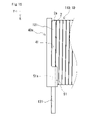
Thefirst holding member 40a is arranged between the end face of the body portion 110 on the first end portion 121 side and the first end core portion 310 of the magnetic core 30, as shown in FIG. The first holding member 40 a ensures electrical insulation between the body portion 110 and the first end core portion 310 . Hereinafter, the configuration of the first holding member 40a will be described in detail with reference to FIGS. 13 to 15. FIG. FIG. 13 is a diagram of the first holding member 40a viewed from the inside. FIG. 14 is a perspective view of the first holding member 40a as seen from the inside. The inner side of the first holding member 40a is the side facing the end face of the main body portion 110 on the first end portion 121 side shown in FIG. That is, the inner side of the first holding member 40a faces the first end turn 2a. The outer side of the first holding member 40 a faces the first end core portion 310 . The inner side of the first holding member 40a is the rear side. The outside of the first holding member 40a is the front side. In FIG. 13, the first terminal portion 131 and the first end turn 2a are indicated by two-dot chain lines. In FIG. 15, some turns 2 including the first end turn 2a are indicated by solid lines.
第一保持部材40aは、図2に示すように、本体部110の第一端部121側の端面と磁性コア30の第一エンドコア部310との間に配置される。第一保持部材40aは、本体部110と第一エンドコア部310との電気的絶縁を確保する。以下、図13から図15を参照して、第一保持部材40aの構成を詳しく説明する。図13は、第一保持部材40aを内側から見た図である。図14は、第一保持部材40aを内側から見た斜視図である。第一保持部材40aの内側とは、図3に示す本体部110の第一端部121側の端面と向かい合う側である。つまり、第一保持部材40aの内側は、第一端部ターン2aと向かい合う。第一保持部材40aの外側は、第一エンドコア部310と向かい合う。第一保持部材40aの内側は背面側である。第一保持部材40aの外側は正面側である。図13では、第一端末部131と第一端部ターン2aとを二点鎖線で示している。図15では、第一端部ターン2aを含む一部のターン2を実線で示している。 (First holding member)
The
図13、図14に示すように、第一保持部材40aは枠状の部材である。第一保持部材40aの形状は、本体部110の端面に対応した形状である。本実施形態では、第一保持部材40aは矩形枠状である。
As shown in FIGS. 13 and 14, the first holding member 40a is a frame-shaped member. The shape of the first holding member 40 a is a shape corresponding to the end face of the main body portion 110 . In this embodiment, the first holding member 40a has a rectangular frame shape.
〈第一面〉
第一保持部材40aは第一面41を有する。第一面41は、図13に示すように、本体部110の第一端部121側の端面を構成する第一端部ターン2aと向かい合う。 <First page>
The first retainingmember 40 a has a first surface 41 . As shown in FIG. 13, the first surface 41 faces the first end turn 2a forming the end surface of the main body 110 on the first end 121 side.
第一保持部材40aは第一面41を有する。第一面41は、図13に示すように、本体部110の第一端部121側の端面を構成する第一端部ターン2aと向かい合う。 <First page>
The first retaining
第一面41は第一領域42を有する。第一領域42は、第一面41のうち、第一端部ターン2aに接する領域である。第一領域42は、第一面41に接する第一端部ターン2aを、本体部110の軸方向の第二の方向に押圧する。第二の方向は、上述した第一の方向とは逆向きである。即ち、第二の方向は、第一端部121から第二端部122に向かう方向である。換言すれば、第二の方向は、第一端部ターン2aを隣り合うターン2に近づける方向である。第二の方向は、正面から背面に向かう方向と一致する。本実施形態では、図14に示すように、第一領域42が、第一端部ターン2aに対応するように螺旋状に傾斜している。図12に示すように第一保持部材40aをコイル10に組み付けたとき、第一領域42によって、第一端部ターン2aを第二の方向に押圧することが可能である。第一端部ターン2aが押圧されることで、第一端末部131が本体部110の軸方向と直交する方向に矯正される。
The first surface 41 has a first area 42 . The first region 42 is a region of the first surface 41 that contacts the first end turn 2a. The first region 42 presses the first end turn 2 a contacting the first surface 41 in the second axial direction of the body portion 110 . The second direction is opposite to the first direction described above. That is, the second direction is the direction from the first end 121 to the second end 122 . In other words, the second direction is the direction that brings the first end turn 2a closer to the adjacent turn 2. As shown in FIG. The second direction corresponds to the direction from the front to the back. In this embodiment, as shown in FIG. 14, the first region 42 is spirally inclined so as to correspond to the first end turn 2a. When the first retaining member 40a is assembled to the coil 10 as shown in FIG. 12, the first region 42 allows the first end turn 2a to be pressed in the second direction. By pressing the first end turn 2 a , the first end portion 131 is corrected in a direction perpendicular to the axial direction of the body portion 110 .
〈固定部〉
第一保持部材40aは固定部51を有する。固定部51は第一端末部131を保持する。固定部51は、第一端部ターン2aから第一端末部131が引き出される部分に形成されている。本実施形態では、図4に示すように、固定部51は、第一保持部材40aを正面から見たときの右上角部に設けられている。第一保持部材40aの右とは、例えば図4であれば、紙面右側である。図13であれば、紙面左側である。固定部51は、本体部110の第一端部121の外周面の一部を覆う。 <Fixed part>
The first holdingmember 40 a has a fixing portion 51 . The fixed portion 51 holds the first terminal portion 131 . The fixing portion 51 is formed at a portion where the first terminal portion 131 is pulled out from the first end turn 2a. In this embodiment, as shown in FIG. 4, the fixing portion 51 is provided at the upper right corner when the first holding member 40a is viewed from the front. The right side of the first holding member 40a is, for example, the right side of the paper surface in FIG. In the case of FIG. 13, it is on the left side of the paper surface. The fixing portion 51 covers part of the outer peripheral surface of the first end portion 121 of the main body portion 110 .
第一保持部材40aは固定部51を有する。固定部51は第一端末部131を保持する。固定部51は、第一端部ターン2aから第一端末部131が引き出される部分に形成されている。本実施形態では、図4に示すように、固定部51は、第一保持部材40aを正面から見たときの右上角部に設けられている。第一保持部材40aの右とは、例えば図4であれば、紙面右側である。図13であれば、紙面左側である。固定部51は、本体部110の第一端部121の外周面の一部を覆う。 <Fixed part>
The first holding
固定部51はスリット51sを有する。スリット51sは第一端末部131に貫通される。スリット51sは、本体部110の軸方向と直交する方向に延びている。スリット51sは、第一保持部材40aの側面に開口している。スリット51sの開口形状は、平角線1の断面に対応した形状である。スリット51sの開口形状とは、スリット51sの軸方向から見た、スリット51sの輪郭の形状である。本実施形態では、スリット51sの開口形状が矩形状である。スリット51sは、第一端末部131を挿入するためのクリアランスを有することを許容する。固定部51は、第一端末部131を完全に不動に保持することを意図していない。つまり、第一端末部131とバスバー61との接続に支障がない程度にスリット51s内で第一端末部131が本体部110の軸方向に移動することは許容される。
The fixed part 51 has a slit 51s. The slit 51s penetrates through the first terminal portion 131 . The slit 51 s extends in a direction orthogonal to the axial direction of the body portion 110 . The slit 51s opens on the side surface of the first holding member 40a. The shape of the opening of the slit 51s is a shape corresponding to the cross section of the flat wire 1 . The opening shape of the slit 51s is the shape of the contour of the slit 51s as seen from the axial direction of the slit 51s. In this embodiment, the opening shape of the slit 51s is rectangular. The slit 51s allows to have a clearance for inserting the first terminal portion 131 . The fixed portion 51 is not intended to hold the first terminal portion 131 completely immobile. That is, the first terminal portion 131 is allowed to move in the axial direction of the main body portion 110 within the slit 51s to the extent that the connection between the first terminal portion 131 and the busbar 61 is not hindered.
スリット51sは第一端末部131の全周を囲むように形成されている。図15に示すように、スリット51sの内周面のうち、第一面41側に位置する面は第一面41と面一になっている。
The slit 51 s is formed so as to surround the entire circumference of the first terminal portion 131 . As shown in FIG. 15, of the inner peripheral surfaces of the slit 51s, the surface located on the side of the first surface 41 is flush with the first surface 41. As shown in FIG.
〈貫通孔〉
第一保持部材40aは貫通孔43を有する。貫通孔43には、図12に示す内側コア部30iの端部が挿入される。貫通孔43の形状は、内側コア部30iの端部の外周形状に概ね対応した形状である。本実施形態では、貫通孔43の形状が矩形状である。 <Through hole>
The first holdingmember 40 a has a through hole 43 . An end portion of the inner core portion 30 i shown in FIG. 12 is inserted into the through hole 43 . The shape of the through hole 43 is a shape that generally corresponds to the outer peripheral shape of the end portion of the inner core portion 30i. In this embodiment, the shape of the through-hole 43 is rectangular.
第一保持部材40aは貫通孔43を有する。貫通孔43には、図12に示す内側コア部30iの端部が挿入される。貫通孔43の形状は、内側コア部30iの端部の外周形状に概ね対応した形状である。本実施形態では、貫通孔43の形状が矩形状である。 <Through hole>
The first holding
〈内側突起〉
更に、第一保持部材40aは内側突起45を有する。内側突起45は、本体部110と内側コア部30iとの間に配置される。内側突起45は、貫通孔43を構成する第一保持部材40aの内周面から貫通孔43の軸方向に突出する。図13に示すように本体部110の内側に内側コア部30iが配置されたとき、内側突起45によって、本体部110の内周面と内側コア部30iの外周面との間に隙間が形成される。その隙間により、本体部110とミドルコア部300との電気的絶縁を確保することができる。また、第一保持部材40aをコイル10に組み付けたとき、内側突起45によって、コイル10に対して第一保持部材40aを位置決めできる。内側突起45の数や位置は特に限定されない。内側突起45は、本体部110の内周面の各辺に対応する箇所に形成されていてもよい。本実施形態では、内側突起45は、第一保持部材40aの内周面のうち、上下の辺に1つずつ、両側の辺に2つずつ設けられている。 <Inner protrusion>
Further, the first retainingmember 40a has an inner projection 45. As shown in FIG. The inner projection 45 is arranged between the main body portion 110 and the inner core portion 30i. The inner protrusion 45 protrudes in the axial direction of the through-hole 43 from the inner peripheral surface of the first holding member 40 a forming the through-hole 43 . When the inner core portion 30i is arranged inside the main body portion 110 as shown in FIG. be. The gap can ensure electrical insulation between main body portion 110 and middle core portion 300 . Further, when the first holding member 40 a is assembled to the coil 10 , the inner protrusions 45 can position the first holding member 40 a with respect to the coil 10 . The number and positions of the inner protrusions 45 are not particularly limited. The inner protrusions 45 may be formed at locations corresponding to respective sides of the inner peripheral surface of the main body portion 110 . In this embodiment, the inner protrusions 45 are provided on the inner peripheral surface of the first holding member 40a, one on each of the upper and lower sides, and two on each of both sides.
更に、第一保持部材40aは内側突起45を有する。内側突起45は、本体部110と内側コア部30iとの間に配置される。内側突起45は、貫通孔43を構成する第一保持部材40aの内周面から貫通孔43の軸方向に突出する。図13に示すように本体部110の内側に内側コア部30iが配置されたとき、内側突起45によって、本体部110の内周面と内側コア部30iの外周面との間に隙間が形成される。その隙間により、本体部110とミドルコア部300との電気的絶縁を確保することができる。また、第一保持部材40aをコイル10に組み付けたとき、内側突起45によって、コイル10に対して第一保持部材40aを位置決めできる。内側突起45の数や位置は特に限定されない。内側突起45は、本体部110の内周面の各辺に対応する箇所に形成されていてもよい。本実施形態では、内側突起45は、第一保持部材40aの内周面のうち、上下の辺に1つずつ、両側の辺に2つずつ設けられている。 <Inner protrusion>
Further, the first retaining
(第一保持部材の組み付け方法)
図7、図12を参照して、第一保持部材40aの組み付け方法を説明する。図7に示すように、本体部110の第一端部121に対して、第一保持部材40aを本体部110の端面に沿う方向にスライドさせる。第一保持部材40aをスライドさせることによって、第一端末部131をスリット51sに挿通する。第一保持部材40aをスライドさせた後、第一保持部材40aを本体部110の第一端部121に押し付けて、第一保持部材40aを第一端部121に嵌め込む。これにより、図12に示すように、第一保持部材40aを本体部110の第一端部121に組み付けることができる。第一端部ターン2aが隣り合うターン2と離れていることで、第一端末部131をスリット51sに挿通し易い。第一保持部材40aをコイル10に組み付けた状態では、第一端部ターン2aが第一保持部材40aに押圧されることによって弾性変形し、第一端末部131が閉じた状態になる。図12では、第一端部ターン2aが隣り合うターン2と離れているように図示されているが、実際には、第一端部ターン2aが第一保持部材40aに押圧されることによって、第一端部ターン2aが隣り合うターン2と接している。 (Method of assembling the first holding member)
A method of assembling the first holdingmember 40a will be described with reference to FIGS. 7 and 12. FIG. As shown in FIG. 7 , the first holding member 40 a is slid along the end surface of the body portion 110 with respect to the first end portion 121 of the body portion 110 . By sliding the first holding member 40a, the first terminal portion 131 is inserted through the slit 51s. After sliding the first holding member 40 a , the first holding member 40 a is pressed against the first end portion 121 of the body portion 110 to fit the first holding member 40 a into the first end portion 121 . As a result, the first holding member 40a can be assembled to the first end portion 121 of the body portion 110, as shown in FIG. Since the first end portion turn 2a is separated from the adjacent turn 2, the first terminal portion 131 can be easily inserted into the slit 51s. When the first holding member 40a is assembled to the coil 10, the first end turn 2a is elastically deformed by being pressed by the first holding member 40a, and the first end portion 131 is closed. In FIG. 12, the first end turn 2a is shown separated from the adjacent turns 2, but in reality, the first end turn 2a is pressed against the first holding member 40a. The first end turn 2a is in contact with adjacent turns 2. As shown in FIG.
図7、図12を参照して、第一保持部材40aの組み付け方法を説明する。図7に示すように、本体部110の第一端部121に対して、第一保持部材40aを本体部110の端面に沿う方向にスライドさせる。第一保持部材40aをスライドさせることによって、第一端末部131をスリット51sに挿通する。第一保持部材40aをスライドさせた後、第一保持部材40aを本体部110の第一端部121に押し付けて、第一保持部材40aを第一端部121に嵌め込む。これにより、図12に示すように、第一保持部材40aを本体部110の第一端部121に組み付けることができる。第一端部ターン2aが隣り合うターン2と離れていることで、第一端末部131をスリット51sに挿通し易い。第一保持部材40aをコイル10に組み付けた状態では、第一端部ターン2aが第一保持部材40aに押圧されることによって弾性変形し、第一端末部131が閉じた状態になる。図12では、第一端部ターン2aが隣り合うターン2と離れているように図示されているが、実際には、第一端部ターン2aが第一保持部材40aに押圧されることによって、第一端部ターン2aが隣り合うターン2と接している。 (Method of assembling the first holding member)
A method of assembling the first holding
(第二保持部材)
第二保持部材40bは、図2に示すように、本体部110の第二端部122側の端面と磁性コア30の第二エンドコア部320との間に配置される。第二保持部材40bは、本体部110と第二エンドコア部320との電気的絶縁を確保する。以下、図16、図17を参照して、第二保持部材40bの構成を詳しく説明する。図16は、第二保持部材40bを外側から見た斜視図である。図17は、第二保持部材40bを内側から見た図である。第二保持部材40bの内側とは、図3に示す本体部110の第二端部122側の端面と向かい合う側である。つまり、第二保持部材40bの内側は、第二端部ターン2bと向かい合う。第二保持部材40bの外側は、第二エンドコア部320と向かい合う。第二保持部材40bの内側は正面側である。第二保持部材40bの外側は背面側である。図17では、第二端末部132と第二端部ターン2bとを二点鎖線で示している。第二保持部材40bの構成は、上述した第一保持部材40aの構成と同様である。以下では、第二保持部材40bについて、第一保持部材40aの相違点を中心に説明する。第一保持部材40aと共通する構成については、同一符号を付して詳細な説明を省略する。 (Second holding member)
Thesecond holding member 40b is arranged between the end surface of the body portion 110 on the side of the second end portion 122 and the second end core portion 320 of the magnetic core 30, as shown in FIG. The second holding member 40 b ensures electrical insulation between the body portion 110 and the second end core portion 320 . Hereinafter, the configuration of the second holding member 40b will be described in detail with reference to FIGS. 16 and 17. FIG. FIG. 16 is a perspective view of the second holding member 40b as seen from the outside. FIG. 17 is a view of the second holding member 40b as seen from the inside. The inside of the second holding member 40b is the side facing the end surface of the main body 110 on the side of the second end 122 shown in FIG. That is, the inner side of the second holding member 40b faces the second end turn 2b. The outer side of the second holding member 40 b faces the second end core portion 320 . The inside of the second holding member 40b is the front side. The outside of the second holding member 40b is the rear side. In FIG. 17, the second terminal portion 132 and the second end turn 2b are indicated by two-dot chain lines. The configuration of the second holding member 40b is the same as the configuration of the first holding member 40a described above. Below, the second holding member 40b will be described, focusing on the differences from the first holding member 40a. Configurations common to the first holding member 40a are denoted by the same reference numerals, and detailed description thereof is omitted.
第二保持部材40bは、図2に示すように、本体部110の第二端部122側の端面と磁性コア30の第二エンドコア部320との間に配置される。第二保持部材40bは、本体部110と第二エンドコア部320との電気的絶縁を確保する。以下、図16、図17を参照して、第二保持部材40bの構成を詳しく説明する。図16は、第二保持部材40bを外側から見た斜視図である。図17は、第二保持部材40bを内側から見た図である。第二保持部材40bの内側とは、図3に示す本体部110の第二端部122側の端面と向かい合う側である。つまり、第二保持部材40bの内側は、第二端部ターン2bと向かい合う。第二保持部材40bの外側は、第二エンドコア部320と向かい合う。第二保持部材40bの内側は正面側である。第二保持部材40bの外側は背面側である。図17では、第二端末部132と第二端部ターン2bとを二点鎖線で示している。第二保持部材40bの構成は、上述した第一保持部材40aの構成と同様である。以下では、第二保持部材40bについて、第一保持部材40aの相違点を中心に説明する。第一保持部材40aと共通する構成については、同一符号を付して詳細な説明を省略する。 (Second holding member)
The
図16、図17に示すように、第二保持部材40bは枠状の部材である。第二保持部材40bの形状は、第一保持部材40aと同様に、矩形枠状である。
As shown in FIGS. 16 and 17, the second holding member 40b is a frame-shaped member. The shape of the second holding member 40b is a rectangular frame like the first holding member 40a.
〈第一面〉
第二保持部材40bは第一面41を有する。第一面41は、図17に示すように、本体部110の第二端部122側の端面を構成する第二端部ターン2bと向かい合う。第一面41は、第一保持部材40aと同様に、第二端部ターン2bに接する第一領域42を有している。第一領域42は、第一面41に接する第二端部ターン2bを、本体部110の軸方向の第一の方向に押圧する。第一の方向は、第二端部122から第一端部121に向かう方向である。換言すれば、第一の方向は、第二端部ターン2bを隣り合うターン2に近づける方向である。ここでは、図示していないが、第一領域42は、第二端部ターン2bに対応するように螺旋状に傾斜している。図12に示すように第一保持部材40aをコイル10に組み付けたとき、第一領域42によって、第二端部ターン2bを第一の方向に押圧することが可能である。 <First page>
The second retainingmember 40 b has a first surface 41 . As shown in FIG. 17, the first surface 41 faces the second end turn 2b that forms the end surface of the main body 110 on the second end 122 side. The first face 41, like the first retaining member 40a, has a first region 42 that contacts the second end turn 2b. The first region 42 presses the second end turn 2 b contacting the first surface 41 in the first axial direction of the body portion 110 . The first direction is the direction from the second end 122 toward the first end 121 . In other words, the first direction is the direction that brings the second end turn 2b closer to the adjacent turn 2. As shown in FIG. Here, although not shown, the first region 42 is spirally inclined so as to correspond to the second end turn 2b. When the first retaining member 40a is assembled to the coil 10 as shown in FIG. 12, the first region 42 allows the second end turn 2b to be pressed in the first direction.
第二保持部材40bは第一面41を有する。第一面41は、図17に示すように、本体部110の第二端部122側の端面を構成する第二端部ターン2bと向かい合う。第一面41は、第一保持部材40aと同様に、第二端部ターン2bに接する第一領域42を有している。第一領域42は、第一面41に接する第二端部ターン2bを、本体部110の軸方向の第一の方向に押圧する。第一の方向は、第二端部122から第一端部121に向かう方向である。換言すれば、第一の方向は、第二端部ターン2bを隣り合うターン2に近づける方向である。ここでは、図示していないが、第一領域42は、第二端部ターン2bに対応するように螺旋状に傾斜している。図12に示すように第一保持部材40aをコイル10に組み付けたとき、第一領域42によって、第二端部ターン2bを第一の方向に押圧することが可能である。 <First page>
The second retaining
〈固定部〉
第二保持部材40bは固定部52を有する。固定部52は第二端末部132を保持する。固定部52は、第二端部ターン2bから第二端末部132が引き出される部分に形成されている。本実施形態では、図4に示すように、固定部52は、第二保持部材40bを正面から見たときの左上角部に設けられている。第二保持部材40bの左とは、例えば図16であれば、紙面右側である。図17であれば、紙面左側である。固定部52は、図16に示すように、第二保持部材40bの外側の面から軸方向に突出している。 <Fixed part>
The second holdingmember 40 b has a fixing portion 52 . The fixed portion 52 holds the second terminal portion 132 . The fixing portion 52 is formed at a portion where the second terminal portion 132 is pulled out from the second end turn 2b. In this embodiment, as shown in FIG. 4, the fixing portion 52 is provided at the upper left corner when the second holding member 40b is viewed from the front. The left side of the second holding member 40b is, for example, the right side of the drawing in FIG. In FIG. 17, it is on the left side of the paper surface. As shown in FIG. 16, the fixing portion 52 axially protrudes from the outer surface of the second holding member 40b.
第二保持部材40bは固定部52を有する。固定部52は第二端末部132を保持する。固定部52は、第二端部ターン2bから第二端末部132が引き出される部分に形成されている。本実施形態では、図4に示すように、固定部52は、第二保持部材40bを正面から見たときの左上角部に設けられている。第二保持部材40bの左とは、例えば図16であれば、紙面右側である。図17であれば、紙面左側である。固定部52は、図16に示すように、第二保持部材40bの外側の面から軸方向に突出している。 <Fixed part>
The second holding
固定部52はスリット52sを有する。スリット52sは第二端末部132に貫通される。スリット52sは、本体部110の軸方向に沿う方向に延びている。スリット51sは、第二保持部材40bの外側の面に開口している。スリット52sの開口形状は、平角線1の断面に対応した形状、即ち矩形状である。スリット52sは第二端末部132の全周を囲むように形成されている。図17に示すように、スリット52sは、第一面41にほぼ直交している。スリット52sは、第二端末部132を挿入するためのクリアランスを有することを許容する。固定部52は、上述した固定部51と同様に、第二端末部132を完全に不動に保持することを意図していない。
The fixed part 52 has a slit 52s. The slit 52s penetrates through the second terminal portion 132 . The slit 52s extends along the axial direction of the body portion 110 . The slit 51s opens on the outer surface of the second holding member 40b. The opening shape of the slit 52s is a shape corresponding to the cross section of the rectangular wire 1, that is, a rectangular shape. The slit 52 s is formed so as to surround the entire circumference of the second terminal portion 132 . As shown in FIG. 17, the slit 52s is substantially orthogonal to the first surface 41. As shown in FIG. The slit 52s allows to have clearance for inserting the second end portion 132 . The fixing portion 52 is not intended to hold the second terminal portion 132 completely immobile, like the fixing portion 51 described above.
〈貫通孔・内側突起〉
第二保持部材40bは、第一保持部材40aと同様に、貫通孔43と内側突起45とを有する。 <Through-hole/inside projection>
Thesecond holding member 40b has a through hole 43 and an inner projection 45, like the first holding member 40a.
第二保持部材40bは、第一保持部材40aと同様に、貫通孔43と内側突起45とを有する。 <Through-hole/inside projection>
The
(第二保持部材の組み付け方法)
図7、図12を参照して、第二保持部材40bの組み付け方法を説明する。図7に示すように、第二保持部材40bを本体部110の軸方向に沿う方向に移動させて、第二端末部132をスリット52sに挿通する。第二保持部材40bを本体部110の第二端部122に押し付けて、第二保持部材40bを第二端部122に嵌め込む。これにより、図12に示すように、第二保持部材40bを本体部110の第二端部122に組み付けることができる。 (Method of assembling the second holding member)
A method of assembling the second holdingmember 40b will be described with reference to FIGS. As shown in FIG. 7, the second holding member 40b is moved in the axial direction of the body portion 110 to insert the second terminal portion 132 into the slit 52s. The second holding member 40 b is pressed against the second end portion 122 of the body portion 110 to fit the second holding member 40 b into the second end portion 122 . Thereby, as shown in FIG. 12, the second holding member 40b can be assembled to the second end portion 122 of the body portion 110. As shown in FIG.
図7、図12を参照して、第二保持部材40bの組み付け方法を説明する。図7に示すように、第二保持部材40bを本体部110の軸方向に沿う方向に移動させて、第二端末部132をスリット52sに挿通する。第二保持部材40bを本体部110の第二端部122に押し付けて、第二保持部材40bを第二端部122に嵌め込む。これにより、図12に示すように、第二保持部材40bを本体部110の第二端部122に組み付けることができる。 (Method of assembling the second holding member)
A method of assembling the second holding
上述した実施形態のリアクトル100は、保持部材40によって、コイル10の端末部130の位置を規制できる。特に、本体部110の端面に沿う方向に引き出された第一端末部131が、第一保持部材40aの固定部51に形成されたスリット51sに挿入される。そのため、第一端末部131が本体部110の軸方向にずれることを効果的に抑制できる。よって、第一端末部131の位置が十分に規制される。
In the reactor 100 of the embodiment described above, the holding member 40 can regulate the position of the terminal portion 130 of the coil 10 . In particular, the first terminal portion 131 pulled out in the direction along the end surface of the main body portion 110 is inserted into the slit 51s formed in the fixed portion 51 of the first holding member 40a. Therefore, it is possible to effectively suppress the displacement of the first terminal portion 131 in the axial direction of the main body portion 110 . Therefore, the position of the first terminal portion 131 is sufficiently restricted.
第一保持部材40aは、本体部110の端面に沿う方向にスライドさせて、本体部110の第一端部121に組み付けられる。第一端末部131がスリット51sに挿入されることで、第一保持部材40aが第一端部121から外れ難くなる。また、スリット51sの内周面のうち、第一面41側に位置する面が第一面41と面一になっていることで、第一面41をガイドにして、第一端末部131をスリット51sに挿入し易い。
The first holding member 40a is assembled to the first end portion 121 of the main body portion 110 by sliding in the direction along the end surface of the main body portion 110. As shown in FIG. By inserting the first terminal portion 131 into the slit 51 s, the first holding member 40 a becomes difficult to come off from the first end portion 121 . In addition, of the inner peripheral surfaces of the slits 51s, the surface located on the first surface 41 side is flush with the first surface 41, so that the first terminal portion 131 can be moved by using the first surface 41 as a guide. It is easy to insert into the slit 51s.
コイル10における本体部110を構成する各ターン2は、平角線1の外周部1eが内周部1iに対して第一の方向に傾斜する。ターン2を形成する平角線1が幅方向の途中で屈曲されていることで、コイル10のみの状態で、第一端末部131を本体部110の軸方向の第一の方向に開いた状態にできる。第一保持部材40aをスライドさせて第一端部121に組み付ける際、第一端末部131をスリット51sに挿入し易い。第一保持部材40aを第一端部121に組み付け易い。
In each turn 2 that constitutes the body portion 110 of the coil 10, the outer peripheral portion 1e of the rectangular wire 1 is inclined in the first direction with respect to the inner peripheral portion 1i. Since the flat wire 1 forming the turn 2 is bent halfway in the width direction, the first terminal portion 131 is opened in the first axial direction of the body portion 110 in the state of only the coil 10. can. When the first holding member 40a is slid and attached to the first end portion 121, the first terminal portion 131 can be easily inserted into the slit 51s. It is easy to assemble the first holding member 40 a to the first end portion 121 .
更に、ターン2を形成する平角線1が幅方向の途中で屈曲されていることで、ターン2間の隙間2gを小さくできる。隙間2gが小さいので、本体部110が両端部から軸方向に押されたときに本体部110の全長が短くなり難い。コイル10に保持部材40を組み付けた後、第一端末部131の位置及び第二端末部132の位置がほぼ変わらない。
Furthermore, the rectangular wire 1 forming the turns 2 is bent in the middle in the width direction, so that the gap 2g between the turns 2 can be reduced. Since the gap 2g is small, the overall length of the body portion 110 is less likely to be shortened when the body portion 110 is pushed in the axial direction from both ends. After the holding member 40 is attached to the coil 10, the positions of the first terminal portion 131 and the second terminal portion 132 remain substantially unchanged.
ターン2における内周部1iと外周部1eとの変位量1dが0.1mm以上であることで、第一端末部131を第一の方向に開いた状態にし易く、また、隙間2gを低減し易い。変位量1dが0.5mm以下であることで、平角線1が幅方向の途中で折れ曲がっていることが一見して分かり難い。つまり、従来と遜色ない見栄えのよいコイル10とすることができる。
Since the amount of displacement 1d between the inner peripheral portion 1i and the outer peripheral portion 1e in the turn 2 is 0.1 mm or more, the first terminal portion 131 can be easily opened in the first direction, and the gap 2g can be reduced. easy. Since the amount of displacement 1d is 0.5 mm or less, it is difficult to understand at first glance that the rectangular wire 1 is bent in the middle in the width direction. In other words, the coil 10 can be made to look as good as the conventional one.
実施形態のリアクトル100は、第一端末部131の位置精度が向上するため、第一端末部131に対するバスバー61の接続作業性が向上する。第一端末部131の位置及び第二端末部132の位置がほぼ変わらないため、第一端末部131及び第二端末部132の各端末部130と各バスバー61,62との接続作業を行い易い。
In the reactor 100 of the embodiment, since the positional accuracy of the first terminal portion 131 is improved, the workability of connecting the busbar 61 to the first terminal portion 131 is improved. Since the position of the first terminal portion 131 and the position of the second terminal portion 132 are almost the same, it is easy to perform the work of connecting the terminal portions 130 of the first terminal portion 131 and the second terminal portion 132 to the bus bars 61 and 62. .
[試作例]
実施形態で説明したコイルの製造方法によって、コイル10を製造した。製造するコイル10の仕様は次のとおりとした。本体部110の形状は、四角筒状とした。本体部110の端面の形状は矩形状である。ターン2の数は16ターンとした。 [Prototype example]
Acoil 10 was manufactured by the coil manufacturing method described in the embodiment. The specifications of the coil 10 to be manufactured were as follows. The shape of the main body portion 110 was a square tube. The shape of the end surface of the body portion 110 is rectangular. The number of turns 2 was 16 turns.
実施形態で説明したコイルの製造方法によって、コイル10を製造した。製造するコイル10の仕様は次のとおりとした。本体部110の形状は、四角筒状とした。本体部110の端面の形状は矩形状である。ターン2の数は16ターンとした。 [Prototype example]
A
保持部810によって保持する平角線1の内周部1iの幅は、平角線1の幅の約60%とした。ガイド部820によって保持する平角線1の外周部1eの幅は、平角線1の幅の約30%とした。保持部810に対してガイド部820を下方に変位させた状態でターン2の形成を行った。ガイド部820の変位量Gdは0.2mmに設定した。製造したコイル10を試料No.1とする。
The width of the inner peripheral portion 1i of the flat wire 1 held by the holding portion 810 is about 60% of the width of the flat wire 1. The width of the outer peripheral portion 1e of the flat wire 1 held by the guide portion 820 was set to about 30% of the width of the flat wire 1. As shown in FIG. Turn 2 was formed in a state in which the guide portion 820 was displaced downward with respect to the holding portion 810 . The amount of displacement Gd of the guide portion 820 was set to 0.2 mm. The manufactured coil 10 is referred to as Sample No. 1.
試料No.1について、ターン2における内周部1iと外周部1eとの変位量1dを測定した。変位量1dの測定は、実施形態で説明した測定方法を用いて行った。そして、4つの角部20cにおけるそれぞれの変位量1dを測定して、その平均値を求めた。その結果、ターン2における角部20cでの変位量1dは、平均で0.2mm程度であった。また、4つの直線部20sの中間点におけるそれぞれの変位量を測定して、その平均値を求めた。直線部20sの中間点は、ターン2の周方向に沿った直線部20sの長さの中間点とした。その結果、ターン2における直線部20sでの変位量は、平均で0.1mm程度であった。
Sample No. 1, the amount of displacement 1d between the inner peripheral portion 1i and the outer peripheral portion 1e in the turn 2 was measured. The displacement amount 1d was measured using the measuring method described in the embodiment. Then, the displacement amount 1d of each of the four corners 20c was measured, and the average value was obtained. As a result, the displacement 1d at the corner 20c of the turn 2 was about 0.2 mm on average. In addition, the displacement amount was measured at each intermediate point of the four linear portions 20s, and the average value was obtained. The midpoint of the straight portion 20 s is the midpoint of the length of the straight portion 20 s along the circumferential direction of the turn 2 . As a result, the displacement amount at the straight portion 20s of the turn 2 was about 0.1 mm on average.
直線部20sでの変位量が角部20cでの変位量よりも小さくなった理由は、次のように考えられる。エッジワイズ曲げ加工時に平角線1の内周部1iを支持体812とフランジ813とで挟むので、内周部1iが固定される。そのため、角部20cでは、平角線1が折り曲げられ易い。これに対し、直線部20sでは、支持体812とフランジ813とが内周部1iとの間に隙間が形成されるような間隔で保持されているため、角部20cに比べて平角線1を折り曲げる力が加わり難い。このような、平角線1と、保持部810及びガイド部820との関係により、角部20cに比べて直線部20sの変位量が小さくなるものと考えられる。
The reason why the amount of displacement at the straight portion 20s is smaller than that at the corner portion 20c is considered as follows. Since the inner peripheral portion 1i of the rectangular wire 1 is sandwiched between the support 812 and the flange 813 during edgewise bending, the inner peripheral portion 1i is fixed. Therefore, the rectangular wire 1 is easily bent at the corner portion 20c. On the other hand, in the straight portion 20s, the supporting body 812 and the flange 813 are held at such a distance that a gap is formed between them and the inner peripheral portion 1i. It is difficult to apply bending force. Due to such a relationship between the flat wire 1, the holding portion 810, and the guide portion 820, it is considered that the displacement amount of the straight portion 20s is smaller than that of the corner portion 20c.
試料No.1の外観を目視で検査した。その結果、ターン2における平角線が幅方向の途中で折れ曲がっていることが一見して分からなかった。また、試料No.1では、本体部110の第一端部121において、第一端部ターン2aと、第一端部ターン2aに隣り合うターン2との間に隙間が形成されていた。つまり、第一端末部131が第一の方向に開いた状態になっていた。第一端部ターン2aと隣接するターン2との隙間は1.0mm程度である。この隙間は、第一端部ターン2aと隣接するターン2との隙間のうち、最も広い部分の隙間である。試料No.1について、本体部110の第一端部121に第一保持部材40aを組み付けたところ、容易に組み付けることができた。
Sample No. The appearance of No. 1 was visually inspected. As a result, it was not apparent at first glance that the flat wire in turn 2 was bent in the middle of the width direction. Moreover, sample no. 1, at the first end portion 121 of the body portion 110, a gap is formed between the first end turn 2a and the turn 2 adjacent to the first end turn 2a. In other words, the first terminal portion 131 was open in the first direction. The gap between the first end turn 2a and the adjacent turn 2 is about 1.0 mm. This gap is the widest part of the gap between the first end turn 2a and the adjacent turn 2. As shown in FIG. Sample no. 1, when the first holding member 40a was assembled to the first end portion 121 of the main body portion 110, the assembly could be easily performed.
試料No.1について、ターン2間の隙間2gを測定した。隙間2gの測定は、実施形態で説明した測定方法を用いて行った。その結果、隙間2gは0.03mmであった。
Sample No. 1, a gap of 2 g between turns 2 was measured. The measurement of the gap 2g was performed using the measurement method described in the embodiment. As a result, the gap 2g was 0.03 mm.
ガイド部820の変位量Gdを0mmにした以外は、試料No.1と同じ製造条件でコイルを製造した。このコイルを試料No.10とする。
Except for setting the displacement amount Gd of the guide portion 820 to 0 mm, the sample No. A coil was manufactured under the same manufacturing conditions as in 1. This coil is sample No. 10.
試料No.10では、試料No.1に比べて、本体部110の第一端部121において、第一端部ターン2aと、第一端部ターン2aに隣り合うターン2との間に隙間が小さかった。そのため、第一端末部131が第一の方向に十分に開いていなかった。試料No.10について、本体部110の第一端部121に第一保持部材40aを組み付けるには、第一端末部131を隣接するターン2から離れる方向に押し広げる必要があるなど、組み付け作業性が悪かった。第一端末部131を押し広げたときに、第一端末部131が曲がるおそれある。
Sample No. 10, sample no. 1, at the first end portion 121 of the main body portion 110, the gap between the first end turn 2a and the turn 2 adjacent to the first end turn 2a was smaller. Therefore, the first terminal portion 131 was not sufficiently opened in the first direction. Sample no. 10, in order to assemble the first holding member 40a to the first end portion 121 of the main body portion 110, the first terminal portion 131 needs to be pushed apart in the direction away from the adjacent turn 2, resulting in poor assembly workability. . When the first terminal portion 131 is spread, the first terminal portion 131 may bend.
また、試料No.10について、ターン2間の隙間2gを測定した。隙間2gの測定は、実施形態で説明した測定方法を用いて行った。その結果、隙間2gは0.06mmであった。試料No.1は、試料No.10に比べて、隙間2gが小さく、寸法安定性に優れる。
Also, sample No. 10, a gap of 2 g between turns 2 was measured. The measurement of the gap 2g was performed using the measurement method described in the embodiment. As a result, the gap 2g was 0.06 mm. Sample no. 1 is sample no. Compared to No. 10, the gap 2g is smaller and the dimensional stability is excellent.
<コンバータ・電力変換装置>
実施形態のリアクトル100は、以下の通電条件を満たす用途に利用できる。通電条件は、例えば、最大直流電流が100A以上1000A以下程度であり、平均電圧が100V以上1000V以下程度であり、使用周波数が5kHz以上100kHz以下程度である。実施形態のリアクトル100は、代表的には電気自動車やハイブリッド自動車などの車両などに搭載されるコンバータの構成部品や、このコンバータを備える電力変換装置の構成部品に利用できる。実施形態のリアクトル100は、コイル10の端末部130とバスバー61,62との接続作業性に優れるため、コンバータや電力変換装置の生産性を向上できる。 <Converters/power converters>
Thereactor 100 of the embodiment can be used for applications that satisfy the following energization conditions. The energization conditions are, for example, a maximum DC current of approximately 100 A or more and 1000 A or less, an average voltage of approximately 100 V or more and 1000 V or less, and a working frequency of approximately 5 kHz or more and 100 kHz or less. The reactor 100 of the embodiment can be typically used as a component of a converter mounted in a vehicle such as an electric vehicle or a hybrid vehicle, or as a component of a power conversion device including this converter. Since the reactor 100 of the embodiment has excellent connection workability between the end portions 130 of the coil 10 and the bus bars 61 and 62, productivity of converters and power converters can be improved.
実施形態のリアクトル100は、以下の通電条件を満たす用途に利用できる。通電条件は、例えば、最大直流電流が100A以上1000A以下程度であり、平均電圧が100V以上1000V以下程度であり、使用周波数が5kHz以上100kHz以下程度である。実施形態のリアクトル100は、代表的には電気自動車やハイブリッド自動車などの車両などに搭載されるコンバータの構成部品や、このコンバータを備える電力変換装置の構成部品に利用できる。実施形態のリアクトル100は、コイル10の端末部130とバスバー61,62との接続作業性に優れるため、コンバータや電力変換装置の生産性を向上できる。 <Converters/power converters>
The
ハイブリッド自動車や電気自動車などの車両1200は、図18に示すようにメインバッテリ1210と、メインバッテリ1210に接続される電力変換装置1100と、メインバッテリ1210からの供給電力により駆動して走行に利用されるモータ1220とを備える。モータ1220は、代表的には、3相交流モータであり、走行時、車輪1250を駆動し、回生時、発電機として機能する。ハイブリッド自動車の場合、車両1200は、モータ1220に加えてエンジン1300を備える。図18では、車両1200の充電箇所としてインレットを示すが、プラグを備える形態とすることができる。
A vehicle 1200 such as a hybrid vehicle or an electric vehicle is driven by a main battery 1210, a power conversion device 1100 connected to the main battery 1210, and power supplied from the main battery 1210 as shown in FIG. and a motor 1220 that Motor 1220 is typically a three-phase AC motor, drives wheels 1250 during running, and functions as a generator during regeneration. In the case of a hybrid vehicle, vehicle 1200 includes engine 1300 in addition to motor 1220 . In FIG. 18, an inlet is shown as the charging point of vehicle 1200, but it can be provided with a plug.
電力変換装置1100は、メインバッテリ1210に接続されるコンバータ1110と、コンバータ1110に接続されて、直流と交流との相互変換を行うインバータ1120とを有する。この例に示すコンバータ1110は、車両1200の走行時、200V以上300V以下程度のメインバッテリ1210の入力電圧を400V以上700V以下程度にまで昇圧して、インバータ1120に給電する。コンバータ1110は、回生時、モータ1220からインバータ1120を介して出力される入力電圧をメインバッテリ1210に適合した直流電圧に降圧して、メインバッテリ1210に充電させている。入力電圧は、直流電圧である。インバータ1120は、車両1200の走行時、コンバータ1110で昇圧された直流を所定の交流に変換してモータ1220に給電し、回生時、モータ1220からの交流出力を直流に変換してコンバータ1110に出力している。
A power conversion device 1100 has a converter 1110 connected to a main battery 1210, and an inverter 1120 connected to the converter 1110 for mutual conversion between direct current and alternating current. Converter 1110 shown in this example boosts the input voltage of main battery 1210 from approximately 200 V to 300 V to approximately 400 V to 700 V and supplies power to inverter 1120 when vehicle 1200 is running. During regeneration, converter 1110 steps down the input voltage output from motor 1220 via inverter 1120 to a DC voltage suitable for main battery 1210 to charge main battery 1210 . The input voltage is a DC voltage. Inverter 1120 converts the direct current boosted by converter 1110 into a predetermined alternating current and supplies power to motor 1220 when vehicle 1200 is running, and converts the alternating current output from motor 1220 into direct current during regeneration and outputs the direct current to converter 1110. is doing.
コンバータ1110は、図19に示すように複数のスイッチング素子1111と、スイッチング素子1111の動作を制御する駆動回路1112と、リアクトル1115とを備え、ON/OFFの繰り返しにより入力電圧の変換を行う。入力電圧の変換とは、ここでは昇降圧を行う。スイッチング素子1111には、電界効果トランジスタ、絶縁ゲートバイポーラトランジスタなどのパワーデバイスが利用される。リアクトル1115は、回路に流れようとする電流の変化を妨げようとするコイルの性質を利用し、スイッチング動作によって電流が増減しようとしたとき、その変化を滑らかにする機能を有する。リアクトル1115として、実施形態のリアクトル100を備える。
The converter 1110 includes a plurality of switching elements 1111, a drive circuit 1112 that controls the operation of the switching elements 1111, and a reactor 1115, as shown in FIG. 19, and converts the input voltage by repeating ON/OFF. Conversion of the input voltage means stepping up and down in this case. A power device such as a field effect transistor or an insulated gate bipolar transistor is used for the switching element 1111 . The reactor 1115 has a function of smoothing the change when the current increases or decreases due to the switching operation by using the property of the coil that prevents the change of the current to flow in the circuit. Reactor 100 of the embodiment is provided as reactor 1115 .
車両1200は、コンバータ1110の他、メインバッテリ1210に接続された給電装置用コンバータ1150や、補機類1240の電力源となるサブバッテリ1230とメインバッテリ1210とに接続され、メインバッテリ1210の高圧を低圧に変換する補機電源用コンバータ1160を備える。コンバータ1110は、代表的には、DC-DC変換を行うが、給電装置用コンバータ1150や補機電源用コンバータ1160は、AC-DC変換を行う。給電装置用コンバータ1150のなかには、DC-DC変換を行うものもある。給電装置用コンバータ1150や補機電源用コンバータ1160のリアクトルに、実施形態のリアクトル100と同様の構成を備え、適宜、大きさや形状などを変更したリアクトルを利用できる。また、入力電力の変換を行うコンバータであって、昇圧のみを行うコンバータや降圧のみを行うコンバータに、実施形態のリアクトル100を利用することもできる。
In addition to converter 1110, vehicle 1200 is connected to power feed device converter 1150 connected to main battery 1210, sub-battery 1230 serving as a power source for auxiliary equipment 1240, and main battery 1210 to supply the high voltage of main battery 1210. An accessory power supply converter 1160 for converting to low voltage is provided. Converter 1110 typically performs DC-DC conversion, but power supply device converter 1150 and auxiliary power supply converter 1160 perform AC-DC conversion. Some power supply converters 1150 perform DC-DC conversion. A reactor having the same configuration as the reactor 100 of the embodiment and having a different size, shape, etc., can be used as the reactor of the power supply device converter 1150 or the auxiliary power converter 1160 . In addition, the reactor 100 of the embodiment can also be used for a converter that converts input electric power, that is, a converter that only steps up or a converter that only steps down.
100 リアクトル
10 コイル
110 本体部
120 端部、121 第一端部、122 第二端部
130 端末部、131 第一端末部、132 第二端末部
1 平角線
1i 内周部、1e 外周部、1b 屈曲部
1d 変位量
2 ターン、20s 直線部、20c 角部
2a 第一端部ターン、2b 第二端部ターン
2g 隙間
30 磁性コア、31 第一コア、32 第二コア
30i 内側コア部、30g ギャップ部
300 ミドルコア部
301 第一ミドルコア部、302 第二ミドルコア部
310 第一エンドコア部、320 第二エンドコア部
330 第一サイドコア部、340 第二サイドコア部
40 保持部材、40a 第一保持部材、40b 第二保持部材
41 第一面、42 第一領域
43 貫通孔、45 内側突起
51、52 固定部、51s、52s スリット
61、62 バスバー
800 曲げ加工部
810 保持部、811 シャフト、812 支持体、813 フランジ
812f 第一面、813f 第二面
820 ガイド部、821 ガイド溝
1100 電力変換装置、1110 コンバータ
1111 スイッチング素子、1112 駆動回路
1115 リアクトル、1120 インバータ
1150 給電装置用コンバータ、1160 補機電源用コンバータ
1200 車両
1210 メインバッテリ、1220 モータ
1230 サブバッテリ、1240 補機類、1250 車輪、1300 エンジン
Gd 変位量
L1 本体部の長さReference Signs List 100 reactor 10 coil 110 body 120 end 121 first end 122 second end 130 terminal 131 first terminal 132 second terminal 1 flat wire 1i inner circumference 1e outer circumference 1b Bent portion 1d Displacement 2 turns 20s Straight portion 20c Corner 2a First end turn 2b Second end turn 2g Gap 30 Magnetic core 31 First core 32 Second core 30i Inner core 30g Gap Parts 300 Middle core part 301 First middle core part 302 Second middle core part 310 First end core part 320 Second end core part 330 First side core part 340 Second side core part 40 Holding member 40a First holding member 40b Second Holding member 41 first surface 42 first region 43 through hole 45 inner projection 51, 52 fixing part 51s, 52s slit 61, 62 bus bar 800 bending part 810 holding part 811 shaft 812 support 813 flange 812f First surface 813f Second surface 820 Guide part 821 Guide groove 1100 Power conversion device 1110 Converter 1111 Switching element 1112 Drive circuit 1115 Reactor 1120 Inverter 1150 Power supply device converter 1160 Auxiliary power supply converter 1200 Vehicle 1210 Main Battery 1220 Motor 1230 Sub-battery 1240 Auxiliary equipment 1250 Wheel 1300 Engine Gd Displacement L Length of 1 main body
10 コイル
110 本体部
120 端部、121 第一端部、122 第二端部
130 端末部、131 第一端末部、132 第二端末部
1 平角線
1i 内周部、1e 外周部、1b 屈曲部
1d 変位量
2 ターン、20s 直線部、20c 角部
2a 第一端部ターン、2b 第二端部ターン
2g 隙間
30 磁性コア、31 第一コア、32 第二コア
30i 内側コア部、30g ギャップ部
300 ミドルコア部
301 第一ミドルコア部、302 第二ミドルコア部
310 第一エンドコア部、320 第二エンドコア部
330 第一サイドコア部、340 第二サイドコア部
40 保持部材、40a 第一保持部材、40b 第二保持部材
41 第一面、42 第一領域
43 貫通孔、45 内側突起
51、52 固定部、51s、52s スリット
61、62 バスバー
800 曲げ加工部
810 保持部、811 シャフト、812 支持体、813 フランジ
812f 第一面、813f 第二面
820 ガイド部、821 ガイド溝
1100 電力変換装置、1110 コンバータ
1111 スイッチング素子、1112 駆動回路
1115 リアクトル、1120 インバータ
1150 給電装置用コンバータ、1160 補機電源用コンバータ
1200 車両
1210 メインバッテリ、1220 モータ
1230 サブバッテリ、1240 補機類、1250 車輪、1300 エンジン
Gd 変位量
L1 本体部の長さ
Claims (7)
- 平角線で構成されたエッジワイズ型のコイルと、
前記コイルが配置された磁性コアと、
前記コイルの少なくとも一方の端部に配置された保持部材とを備え、
前記コイルは、
複数のターンで構成された本体部と、
前記本体部の一方の端部から前記本体部の端面に沿う方向に引き出された第一端末部とを有し、
前記保持部材は、
前記本体部の端面と向かい合う第一面と、
前記第一端末部を保持する固定部とを有し、
前記固定部は、前記第一端末部に貫通されるスリットを有する、
リアクトル。 An edgewise coil made of rectangular wire,
a magnetic core on which the coil is arranged;
a holding member disposed at at least one end of the coil;
The coil is
a main body composed of a plurality of turns;
a first terminal portion pulled out from one end of the main body portion in a direction along the end surface of the main body portion;
The holding member is
a first surface facing the end surface of the main body;
a fixing portion that holds the first terminal portion;
The fixing part has a slit that penetrates the first terminal part,
Reactor. - 前記複数のターンの各々は、
前記平角線における前記ターンの内周側を構成する内周部と、
前記平角線における前記ターンの外周側を構成する外周部とを有し、
前記外周部は、前記内周部に対して前記本体部の軸方向の第一の方向に向かって傾くように曲げられている請求項1に記載のリアクトル。 each of the plurality of turns,
an inner peripheral portion forming an inner peripheral side of the turn in the rectangular wire;
and an outer peripheral portion that constitutes the outer peripheral side of the turn in the flat wire,
The reactor according to claim 1, wherein the outer peripheral portion is bent toward the first axial direction of the body portion with respect to the inner peripheral portion. - 前記複数のターンの各々は、前記平角線が屈曲された角部を有し、
前記角部における前記内周部と前記外周部との前記本体部の軸方向の変位量が0.1mm以上0.5mm以下である請求項2に記載のリアクトル。 each of the plurality of turns has a corner where the rectangular wire is bent,
3. The reactor according to claim 2, wherein the amount of displacement in the axial direction of the body between the inner peripheral portion and the outer peripheral portion at the corner is 0.1 mm or more and 0.5 mm or less. - 前記第一面は、第一領域を有し、
前記第一領域は、前記複数のターンのうちの前記第一面に接するターンを、前記本体部の軸方向の第二の方向に押圧する請求項1から請求項3のいずれか1項に記載のリアクトル。 The first surface has a first region,
4. The first region according to any one of claims 1 to 3, wherein the first region presses a turn in contact with the first surface among the plurality of turns in a second axial direction of the body portion. reactor. - 前記磁性コアは、前記本体部の内側に配置される内側コア部を有し、
前記保持部材は、
前記内側コア部の端部が挿入された貫通孔と、
前記本体部と前記内側コア部との間に配置された内側突起とを有する請求項1から請求項4のいずれか一項に記載のリアクトル。 The magnetic core has an inner core portion arranged inside the main body portion,
The holding member is
a through hole into which the end of the inner core portion is inserted;
The reactor according to any one of claims 1 to 4, further comprising an inner protrusion arranged between the main body portion and the inner core portion. - 請求項1から請求項5のいずれか1項に記載のリアクトルを備える、
コンバータ。 Equipped with the reactor according to any one of claims 1 to 5,
converter. - 請求項6に記載のコンバータを備える、
電力変換装置。 comprising a converter according to claim 6,
Power converter.
Priority Applications (1)
| Application Number | Priority Date | Filing Date | Title |
|---|---|---|---|
| CN202280038606.7A CN117396991A (en) | 2021-06-10 | 2022-06-08 | Reactor, converter, and power conversion device |
Applications Claiming Priority (2)
| Application Number | Priority Date | Filing Date | Title |
|---|---|---|---|
| JP2021-097095 | 2021-06-10 | ||
| JP2021097095A JP2022188850A (en) | 2021-06-10 | 2021-06-10 | Reactor, converter, and power conversion device |
Publications (1)
| Publication Number | Publication Date |
|---|---|
| WO2022260089A1 true WO2022260089A1 (en) | 2022-12-15 |
Family
ID=84426083
Family Applications (1)
| Application Number | Title | Priority Date | Filing Date |
|---|---|---|---|
| PCT/JP2022/023143 WO2022260089A1 (en) | 2021-06-10 | 2022-06-08 | Reactor, converter, and power conversion device |
Country Status (3)
| Country | Link |
|---|---|
| JP (1) | JP2022188850A (en) |
| CN (1) | CN117396991A (en) |
| WO (1) | WO2022260089A1 (en) |
Citations (4)
| Publication number | Priority date | Publication date | Assignee | Title |
|---|---|---|---|---|
| JPH1154335A (en) * | 1997-08-04 | 1999-02-26 | Hitachi Ferrite Electronics Ltd | Inductance element |
| JP2009206421A (en) * | 2008-02-29 | 2009-09-10 | Fdk Corp | Choke coil |
| JP2010219473A (en) * | 2009-03-19 | 2010-09-30 | Fdk Corp | Choke coil |
| JP2013026419A (en) * | 2011-07-20 | 2013-02-04 | Sumitomo Electric Ind Ltd | Reactor |
-
2021
- 2021-06-10 JP JP2021097095A patent/JP2022188850A/en active Pending
-
2022
- 2022-06-08 WO PCT/JP2022/023143 patent/WO2022260089A1/en active Search and Examination
- 2022-06-08 CN CN202280038606.7A patent/CN117396991A/en active Pending
Patent Citations (4)
| Publication number | Priority date | Publication date | Assignee | Title |
|---|---|---|---|---|
| JPH1154335A (en) * | 1997-08-04 | 1999-02-26 | Hitachi Ferrite Electronics Ltd | Inductance element |
| JP2009206421A (en) * | 2008-02-29 | 2009-09-10 | Fdk Corp | Choke coil |
| JP2010219473A (en) * | 2009-03-19 | 2010-09-30 | Fdk Corp | Choke coil |
| JP2013026419A (en) * | 2011-07-20 | 2013-02-04 | Sumitomo Electric Ind Ltd | Reactor |
Also Published As
| Publication number | Publication date |
|---|---|
| CN117396991A (en) | 2024-01-12 |
| JP2022188850A (en) | 2022-12-22 |
Similar Documents
| Publication | Publication Date | Title |
|---|---|---|
| US10720820B2 (en) | Rotating electric machine and method for manufacturing the rotating electric machine | |
| JP6098870B2 (en) | Reactor, converter, and power converter | |
| JP5087880B2 (en) | Reactor | |
| JP5109466B2 (en) | Stator for rotating electrical machine, bus bar unit used therefor, and connection structure between bus bar terminal and coil terminal | |
| JP4914287B2 (en) | Insulator, split stator, and stator for rotating electrical machine | |
| CN109075668B (en) | Method for manufacturing armature, method for manufacturing rotating electrical machine, armature, rotating electrical machine, and apparatus for manufacturing armature | |
| EP3540917B1 (en) | Rotary electric machine | |
| JP2011209158A (en) | Current sensor assembly and method for assembling the same | |
| JP2010110144A (en) | Wiring component for motor coil | |
| JP2009273216A (en) | Motor | |
| JP2014112612A (en) | Winding structure, coil winding, coil component, and method for manufacturing coil winding | |
| US8866580B2 (en) | Power converting apparatus | |
| EP3614542A1 (en) | Dynamo-electric machine | |
| JP5694748B2 (en) | Reactor unit for multi-phase converter | |
| WO2022260089A1 (en) | Reactor, converter, and power conversion device | |
| EP1072082A1 (en) | Construction of an electrical machine with individual pole windings | |
| WO2022255429A1 (en) | Coil, reactor, converter, power conversion device, and method for producing coil | |
| US7285892B2 (en) | Stator having teeth with a projecting portion extending outwardly from a winding portion and a yoke portion | |
| JP4465396B2 (en) | Distribution connection structure for rotating electrical machine and method for manufacturing distribution connection structure for rotating electrical machine | |
| JP5381213B2 (en) | Stator manufacturing method and rectangular wire manufacturing apparatus | |
| JP2015188019A (en) | Gap member, magnetic core and reactor | |
| DE112021000536T5 (en) | Anchor and manufacturing method therefor | |
| WO2022260088A1 (en) | Reactor, converter, and power conversion device | |
| WO2023008075A1 (en) | Reactor structure, converter, and electric power conversion device | |
| JP2010267780A (en) | Method of manufacturing coil for reactor |
Legal Events
| Date | Code | Title | Description |
|---|---|---|---|
| 121 | Ep: the epo has been informed by wipo that ep was designated in this application |
Ref document number: 22820268 Country of ref document: EP Kind code of ref document: A1 |
|
| DPE1 | Request for preliminary examination filed after expiration of 19th month from priority date (pct application filed from 20040101) | ||
| NENP | Non-entry into the national phase |
Ref country code: DE |