WO2022259804A1 - 肌処理装置 - Google Patents
肌処理装置 Download PDFInfo
- Publication number
- WO2022259804A1 WO2022259804A1 PCT/JP2022/019968 JP2022019968W WO2022259804A1 WO 2022259804 A1 WO2022259804 A1 WO 2022259804A1 JP 2022019968 W JP2022019968 W JP 2022019968W WO 2022259804 A1 WO2022259804 A1 WO 2022259804A1
- Authority
- WO
- WIPO (PCT)
- Prior art keywords
- head
- cutter unit
- skin treatment
- main body
- holder
- Prior art date
- Legal status (The legal status is an assumption and is not a legal conclusion. Google has not performed a legal analysis and makes no representation as to the accuracy of the status listed.)
- Ceased
Links
Images


Classifications
-
- A—HUMAN NECESSITIES
- A61—MEDICAL OR VETERINARY SCIENCE; HYGIENE
- A61N—ELECTROTHERAPY; MAGNETOTHERAPY; RADIATION THERAPY; ULTRASOUND THERAPY
- A61N1/00—Electrotherapy; Circuits therefor
- A61N1/18—Applying electric currents by contact electrodes
- A61N1/32—Applying electric currents by contact electrodes alternating or intermittent currents
- A61N1/328—Applying electric currents by contact electrodes alternating or intermittent currents for improving the appearance of the skin, e.g. facial toning or wrinkle treatment
-
- A—HUMAN NECESSITIES
- A61—MEDICAL OR VETERINARY SCIENCE; HYGIENE
- A61N—ELECTROTHERAPY; MAGNETOTHERAPY; RADIATION THERAPY; ULTRASOUND THERAPY
- A61N1/00—Electrotherapy; Circuits therefor
- A61N1/02—Details
- A61N1/04—Electrodes
- A61N1/0404—Electrodes for external use
- A61N1/0408—Use-related aspects
- A61N1/0428—Specially adapted for iontophoresis, e.g. AC, DC or including drug reservoirs
-
- A—HUMAN NECESSITIES
- A61—MEDICAL OR VETERINARY SCIENCE; HYGIENE
- A61N—ELECTROTHERAPY; MAGNETOTHERAPY; RADIATION THERAPY; ULTRASOUND THERAPY
- A61N1/00—Electrotherapy; Circuits therefor
- A61N1/02—Details
- A61N1/04—Electrodes
- A61N1/0404—Electrodes for external use
- A61N1/0408—Use-related aspects
- A61N1/0452—Specially adapted for transcutaneous muscle stimulation [TMS]
-
- B—PERFORMING OPERATIONS; TRANSPORTING
- B26—HAND CUTTING TOOLS; CUTTING; SEVERING
- B26B—HAND-HELD CUTTING TOOLS NOT OTHERWISE PROVIDED FOR
- B26B19/00—Clippers or shavers operating with a plurality of cutting edges, e.g. hair clippers, dry shavers
- B26B19/14—Clippers or shavers operating with a plurality of cutting edges, e.g. hair clippers, dry shavers of the rotary-cutter type; Cutting heads therefor; Cutters therefor
-
- B—PERFORMING OPERATIONS; TRANSPORTING
- B26—HAND CUTTING TOOLS; CUTTING; SEVERING
- B26B—HAND-HELD CUTTING TOOLS NOT OTHERWISE PROVIDED FOR
- B26B19/00—Clippers or shavers operating with a plurality of cutting edges, e.g. hair clippers, dry shavers
- B26B19/38—Details of, or accessories for, hair clippers, or dry shavers, e.g. housings, casings, grips, guards
-
- A—HUMAN NECESSITIES
- A61—MEDICAL OR VETERINARY SCIENCE; HYGIENE
- A61N—ELECTROTHERAPY; MAGNETOTHERAPY; RADIATION THERAPY; ULTRASOUND THERAPY
- A61N1/00—Electrotherapy; Circuits therefor
- A61N1/02—Details
- A61N1/04—Electrodes
- A61N1/0404—Electrodes for external use
- A61N1/0472—Structure-related aspects
- A61N1/0476—Array electrodes (including any electrode arrangement with more than one electrode for at least one of the polarities)
Definitions
- the present disclosure relates to a skin treatment device.
- a skin treatment apparatus in the form of an electric shaver with an iontophoresis device provided on the head is known.
- a specific action can be given to a target portion of a user when the head portion contacts the target portion of the user, an effect corresponding to the specific action (for example, hair removal related to shaving) can be achieved.
- the effect of improving efficiency and the effect of appropriate care for the skin after shaving can be expected.
- an object of the present disclosure is to provide a skin treatment device capable of applying a specific action to a target site.
- a head unit capable of contacting a user's target site
- the head section an electric cutter unit, and an action means for applying a specific action to a target portion of the user with which the head unit contacts based on power supplied from a power supply.
- a skin treatment device capable of applying a specific action to a target site.
- FIG. 1 is a front view schematically showing an example of an electric shaver according to the first embodiment
- FIG. FIG. 2 is a schematic diagram illustrating a preferred example of heating means according to Example 1
- 4 is a schematic diagram showing an example of an electrical system in the main body according to Example 1.
- FIG. FIG. 4 is an explanatory diagram of the principle of the heating effect according to Example 1
- 4 is a schematic flow chart showing an example of processing executed by a control unit according to Embodiment 1
- 8 is a schematic flow chart showing another example of processing executed by the control unit according to the first embodiment
- 2 is an exploded perspective view of the entire head portion according to Example 1.
- FIG. 4 is an exploded perspective view of part of the head portion according to Example 1.
- FIG. 4 is a perspective view showing a single main holder unit according to Example 1.
- FIG. FIG. 9 is an explanatory diagram (part 1) of the heating effect of the electric shaver shown in FIGS. 6 to 8;
- FIG. 9 is an explanatory diagram (part 2) of the heating effect of the electric shaver shown in FIGS. 6 to 8;
- FIG. 9 is an explanatory diagram (part 3) of the heating effect of the electric shaver shown in FIGS. 6 to 8;
- 1 is a plan view schematically showing a film heater according to Example 1;
- FIG. 4 is a diagram showing an example of a wiring structure in the head section according to Example 1.
- FIG. 4 is a diagram showing an example of a wiring structure in the head section according to Example 1.
- FIG. 4 is a diagram showing an example of a wiring structure in the head section according to Example 1.
- FIG. 4 is a perspective view showing a held portion of the base according to Example 1.
- FIG. FIG. 10 is a perspective view of the head portion of the electric shaver according to Example 2;
- FIG. 11 is another perspective view of the head portion of the electric shaver according to Example 2;
- FIG. 11 is a perspective view of the base of the electric shaver according to Example 2;
- FIG. 10 is an explanatory diagram of the wiring structure of the present embodiment according to Embodiment 2;
- FIG. 11 is a perspective view from below of the frame according to Example 2;
- FIG. 10 is a perspective view of an electrical connection structure for an electric shaver according to Example 2;
- FIG. 10 is an enlarged perspective view of a characteristic portion of the shaver holder according to Example 2;
- FIG. 10 is a perspective view showing the arrangement of light irradiation units and the like of the electric shaver according to Example 2;
- FIG. 10 is an explanatory diagram of a method for removing the cutter unit of the electric shaver according to Example 2;
- FIG. 10 is a perspective view of the frame of the electric shaver according to Example 2;
- FIG. 10 is a perspective view showing a connecting portion between the head portion and the body portion according to Example 2 from below;
- FIG. 11 is a perspective view of a connecting portion of a main body according to Example 2;
- FIG. 11 is another perspective view of the connecting portion of the main body according to Example 2;
- FIG. 11 is a perspective view of a connecting portion of a head portion according to Example 2;
- FIG. 11 is a perspective view showing a second connecting means according to Example 2;
- FIG. 1 is a front view schematically showing an example of an electric shaver 1, which is one form of a skin treatment apparatus according to this embodiment.
- the term "user” refers to the user of the electric shaver 1
- the user's target site is any site that can be touched by the electric shaver 1, typically including hair to be shaved. corresponds to the part.
- the hair removal efficiency means the hair removal efficiency related to shaving by the electric shaver 1 .
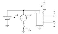
- the electric shaver 1 includes a body portion 10 and a head portion 20, as shown in FIG.
- the main body 10 accommodates the electric motor 11 and the battery 12 .
- the electric motor 11 is a driving source for driving the electric shaver 1 and operates based on electric power from the battery 12 .
- the electric motor 11 may be realized by a magnetic linear motor or the like.
- the battery 12 is an externally rechargeable battery and functions as an internal power supply. It should be noted that in a variant, the electric motor 11 may be operable by an external power source instead of or in addition to the internal battery 12 .
- the main body 10 may be provided with a user interface 15 that allows the user to make various inputs to the electric shaver 1 .
- the user interface 15 may include mechanical buttons, touch switches, and the like.
- the body portion 10 may be provided with a trimmer (not shown).
- the head part 20 has a form that can come into contact with the user's target site.
- the head section 20 may be detachably attached to the main body section 10 . When the head portion 20 is detachable from the main body portion 10, cleaning of the head portion 20 and the like are facilitated.
- the head part 20 may be supported displaceably with respect to the main body part 10 .
- the head portion 20 When the head portion 20 is displaceable with respect to the body portion 10, it becomes easy to bring the head portion 20 into close contact with the user's target site, and the hair removal efficiency can be effectively improved.
- the head portion 20 may be displaceable with various degrees of freedom with respect to the main body portion 10 .
- the head portion 20 may be supported with respect to the main body portion 10 via the shaft member 13.
- the head portion 20 may rotate within a predetermined angle range around any direction perpendicular to the axial direction of the shaft member 13. It may be tiltable or rotatable at .
- a ball joint may be used for the connection structure between the head portion 20 and the main body portion 10 .
- a cutter unit 21 and a heating means 22 are provided in the head portion 20 .
- the cutter unit 21 is provided on the head section 20 so as to contact the target site while the head section 20 is in contact with the user's target site. That is, the cutter unit 21 forms a portion of the head section 20 that comes into contact with the user's target portion. In a normal shaving usage mode, the cutter unit 21 may be the only portion of the head portion 20 that contacts the target portion of the user.
- the cutter unit 21 is an electric type driven by the electric motor 11 .
- the cutter unit 21 has a blade capable of cutting hair during operation (driving). Therefore, when the cutter unit 21 operates while the head unit 20 is in contact with the user's target site, the cutter unit 21 cuts the hair that may exist on the target site (that is, shaving is achieved).
- the cutter unit 21 may be of any type as long as it is electrically driven, and its movement is arbitrary.
- the cutter unit 21 may be of a rotary type, a vibration type (linear vibration), or a combination thereof.
- the heating means 22 heats the target portion of the user with which the cutter unit 21 contacts.
- the heating means 22 heats the user's target region that the cutter unit 21 contacts, thereby assisting the user's target region (particularly, the state of the hair) to reach a state suitable for shaving.
- the heating means 22 achieves the same effect as heating the target site with a steamed towel.
- such an effect of the heating means 22 is also referred to as a "heating effect”.
- the heating means 22 operates based on the power from the battery 12. That is, the power supply voltage for the heating means 22 is generated based on the battery 12 . It should be noted that, in a variant, the heating means 22 may be operable by an external power source instead of or in addition to the internal battery 12 .
- the heating means 22 may have any configuration as long as it can heat the target site, and may include, for example, a heating element (eg, heating wire) that generates heat by applying a direct current.
- a heating element eg, heating wire
- the heating means 22 may be in the form of a film heater, a nichrome wire heater, or the like.
- the heating means 22 may be means for applying a high frequency to the target site using a pair of electrodes 221 as described later.
- the heating means 22 may be realized by a means for irradiating a target site with radio waves such as microwaves (very short waves).
- the heating means 22 preferably heats a relatively wide area of the head portion 20 so that a relatively wide area of the target portion can be heated while the head portion 20 is in contact with the user's target portion.
- the heating means 22 may be arranged so as to occupy most of the portion of the head portion 20 that contacts the target portion of the user, excluding the cutter unit 21 .
- the heating means 22 may be provided so as to surround the cutter unit 21 .
- the heating means 22 is preferably provided in the head portion 20 in a manner that does not impede the adhesion between the cutter unit 21 and the target portion.
- the heating means 22 may be slightly offset from the cutter unit 21 toward the main body 10 (see ⁇ 1 in FIG. 1). As a result, the possibility that the adhesion between the cutter unit 21 and the target portion is lowered due to the heating means 22 can be reduced.
- FIG. 2 is a schematic diagram illustrating a preferred example of the heating means 22.
- FIG. FIG. 2A is a schematic diagram showing an example of an electrical system in the main body 10.
- FIG. FIG. 2 also shows an electrical connection mode between the heating means 22 and the controller 300 .
- the wiring is schematically shown by a solid line.
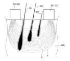
- FIG. 3 is an explanatory diagram of the principle of the heating effect, and is a sectional view schematically showing an electric field (high-frequency current) generated at the target portion 900 when a high-frequency voltage is applied.
- FIG. 3 schematically shows three hairs 901 at a target site 900 along with a pair of electrodes 221 .
- the state of the electric field generated at the target portion 900 by the application of the high-frequency voltage is schematically indicated by the dotted line E.
- FIG. 3 is an explanatory diagram of the principle of the heating effect, and is a sectional view schematically showing an electric field (high-frequency current) generated at the target portion 900 when a high
- the heating means 22 preferably includes a pair of electrodes 221, as shown in FIG. In this case, a high-frequency electric field is formed in the target portion 900 through the pair of electrodes 221, and the target portion 900 is heated by dielectric heating and/or Joule heating.
- the high-frequency electric field can act on a relatively deep portion of the target portion 900 (closer to the pores than the surface). Therefore, the pores are effectively opened, and the heat is transmitted to the hair roots, so that the hair 901 can be softened.
- the state of the user's target portion 900 (particularly, the state of the hair) can be improved compared to the case of using a heating element that generates heat by applying a direct current. state) can be efficiently brought to a state suitable for shaving. That is, the heating effect can be efficiently enhanced.
- the heating means 22 includes a pair of electrodes 221
- one of the pair of electrodes 221 may be realized by a component forming the cutter unit 21 (outer blade portion 2131 as described later).
- the pair of electrodes 221 on the side of the head section 20 are connected to the body section 10 via electrical connection between the electrical contacts 19 on the side of the body section 10 and the electrical contacts 29 on the side of the head section 20 . It is electrically connected to the side controller 300 (and the battery 12 not shown in FIG. 2). In this case, since there is no need to arrange the control unit 300 or a battery (for example, a battery different from the battery 12) on the head unit 20 side, the head unit 20 can be washed.
- the electrical contact 19 and the electrical contact 29 may be provided in pairs corresponding to the pair of electrodes 221 .
- the electrical contact 19 and the electrical contact 29 may be arranged, for example, at the connecting portion between the head portion 20 and the body portion 10 .
- the electrical contact 19 on the body portion 10 side is provided at or near a holding portion that detachably holds the head portion 20 in the body portion 10, and the head portion 20 side is provided at or near the held portion of the head portion 20.
- electrical contacts 29 may be provided.
- the electrical contact 19 and the electrical contact 29 are electrically connected when the head portion 20 is connected (mounted) to the body portion 10, and are electrically connected when the head portion 20 is detached from the body portion 10. can be electrically disconnected.
- the electrical contacts 19 and 29 may be arranged at locations other than the connecting portion between the head portion 20 and the main body portion 10 (positions away from the holding portion described above).
- the electrical contacts 19 and the electrical contacts 29 may be realized by magnetic contacts that come into contact when the head section 20 is connected (attached) to the body section 10 .
- the energization between the electrical contacts 19 and 29 may be achieved by contactless energization (non-contact energization).
- electrical contact 19 may be omitted and electrical contact 29 may be connectable to an external power source.
- the electrical connection between the electrical contact 29 and the external power supply may be realized by a USB (Universal Serial Bus) connection or the like.
- the controller 300 may be electrically connected to the battery 12 in parallel with the electric motor 11, as shown in FIG. 2A.
- the power of the battery 12, which is the power source for the electric motor 11, can be used to operate the heating means 22.
- switch SW is a shaving switch (one element of user interface 15) that turns electric motor 11 on.
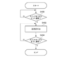
- FIG. 4 is a schematic flow chart showing an example of processing executed by the control unit 300.
- FIG. 4 is a schematic flow chart showing an example of processing executed by the control unit 300.
- the heating means 22 always operates in conjunction with the operation of the cutter unit 21.
- a shaving switch (not shown) is turned on (YES in step S400)
- power supply to the electric motor 11 and the controller 300 is started.
- the controller 300 starts applying the high frequency voltage to the pair of electrodes 221 of the heating means 22 (step S402).
- the user can operate the heating means 22 when shaving with the cutter unit 21 without performing any special operation on the heating means 22, and the operability is improved.
- the shaving switch (not shown) is turned off (YES in step S404)
- the electric motor 11 and the heating means 22 stop because the power supply from the battery 12 is interrupted. That is, when the electric motor 11 is stopped, the cutter unit 21 is stopped and the application of the high-frequency voltage to the pair of electrodes 221 of the heating means 22 is stopped.
- the operation of the heating means 22 is started at substantially the same timing as the operation of the electric motor 11 is started.
- a significant gap from the start timing may be set.
- the timing of starting the operation of the heating means 22 may be significantly earlier than the timing of starting the operation of the electric motor 11 so that shaving is achieved at the target site after it has been heated.
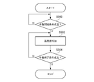
- FIG. 5 is a schematic flowchart showing another example of processing executed by the control unit 300.
- FIG. 5 is a schematic flowchart showing another example of processing executed by the control unit 300.
- the heating means 22 can operate independently of the operation of the cutter unit 21. Specifically, in step S500, control unit 300 determines whether or not the condition for starting the operation of heating means 22 is satisfied.
- the conditions for starting the operation of the heating means 22 are arbitrary and can be varied.
- the condition for starting operation of the heating means 22 may be satisfied by turning on a heating switch (not shown). In such a configuration, if the heating switch (not shown) is provided separately from the shaving switch (see switch SW in FIG. 2A), the heating means 22 is combined with the electric motor 11 which is activated when the shaving switch is turned on. can operate independently.
- the control unit 300 determines whether or not the operation end condition of the heating means 22 is satisfied. (Step S502).
- the conditions for terminating the operation of the heating means 22 are arbitrary and can be varied. For example, the operation termination condition of the heating means 22 may be satisfied by turning off a heating switch (not shown).
- the control unit 300 stops applying the high frequency voltage to the pair of electrodes 221 related to the heating means 22 (step S506).
- the plurality of operation modes include a shaving alone mode in which only the electric motor 11 operates, a shaving and heating mode in which both the electric motor 11 and the heating means 22 operate, and a heating alone mode in which only the heating means 22 operates. may contain.
- the head section 20 may include a temperature sensor for detecting the temperature of the heating means 22 or the target site.
- the control section 300 may perform The heating means 22 may be controlled.
- the controller 300 may control the heating means 22 so that the temperature indicated by the temperature information from the temperature sensor matches a predetermined target value.
- the predetermined target value may be constant, may be selectable by the user from one of a plurality of levels, or may be adjustable (customized) by the user.
- a current sensor may be provided in the head portion 20 or the main body portion 10 .
- the heating by the heating means 22 may be reduced or stopped, and if the temperature or current falls below another threshold, the heating means The degree of heating by 22 may be increased.
- the temperature sensor or the current sensor may be capable of detecting that a foreign substance is attached to the head portion 20, and may reduce the degree of operation of the electric shaver 1 or stop operation when the desired improvement in skin quality cannot be obtained. You may
- the head unit 20 may include a contact or proximity sensor that detects contact or proximity with the target site, in which case the control unit 300 detects the sensor from the contact or proximity sensor. Based on the information, the heating means 22 may be controlled. For example, the control unit 300 may activate the heating means 22 only when sensor information from the contact or proximity sensor indicates contact or proximity between the head unit 20 and the target site.
- the heating means 22 is provided in the head portion 20, a configuration that can transmit the operating state of the heating means 22 to the user can be useful.
- the head section 20 may be provided with a light irradiation section 70 (see FIG. 1).
- the light irradiation unit 70 may be configured to emit light for information transmission. For example, when having a plurality of operation modes as described above with reference to FIG. 5, the light irradiation section 70 may emit light in different colors for each operation mode.
- the light irradiation unit 70 may be realized by a light emitting diode or the like.
- the light irradiation unit 70 may apply light stimulation to the skin according to the frequency of the irradiated light, and is arranged so that the user can visually check the condition of the skin processed by irradiating visible light. good too.
- the light irradiation unit 70 may function as heating means separate from the heating means 22 .
- the light irradiator 70 may irradiate light of a frequency that acts to damage hair roots. In this case, the user may be able to adjust (customize) the on/off of the light irradiation unit 70 and the output when it is on.
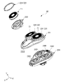
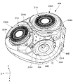
- FIG. 6 is an exploded perspective view of the entire head portion 20, and FIG. 7 is an exploded perspective view of part of the head portion 20.
- FIG. FIG. 8 is a perspective view showing the main holder portion 231 alone.
- FIGS. 6-8 show three orthogonal axes (X-, Y-, and Z-axes) in a right-handed coordinate system.
- the head section 20 includes a cutter unit 21 and heating means 22, and three cutter units 21 and three heating means 22 are provided.
- the number of sets other than three for example, one set, two sets, or four sets or more
- the pair of electrodes 221 of the heating means 22 are formed by an outer blade portion 2131 and a frame portion 224, as will be described later.
- the electrical connection between the three sets of heating means 22 and the control unit 300 (and the battery 12) may be realized by the electrical contacts 19, 29 as shown in FIG.
- Six sets of electrical contacts 19, 29 may be provided, but preferably two sets of electrical contacts 19, 29 are provided for a total of six electrodes 221 associated with the heating means 22 of FIG. In the case of two sets of electrical contacts 19, 29, the six electrodes 221 associated with the three sets of heating means 22 act in common. In this case, the electrical contact structure between the body portion 10 and the head portion 20 can be simplified.
- the head portion 20 includes a base portion 230, a main holder portion 231 (an example of the holder portion), and a shaver holder 232.
- a main holder portion 231 an example of the holder portion
- a shaver holder 232 In the example shown in FIGS. 6 to 8, three sets of shaver holders 232 are provided corresponding to the three sets of cutter units 21 together with frame portions 224 to be described later.
- FIG. 6 only one of the three sets is shown disassembled from the main holder portion 231 .
- Each of the three sets may have a similar configuration, and any one set will be described below unless otherwise specified.
- the base 230 can be detachably connected to the main body 10 (see FIG. 1). Note that the base portion 230 may be supported with respect to the body portion 10 in such a manner that the head portion 20 can be displaced with respect to the body portion 10 as described above.
- the base 230 has a rotary shaft 2301 that rotates as the electric motor 11 rotates.
- the rotating shaft portion 2301 may be provided for each cutter unit 21 . Therefore, in the examples shown in FIGS. 6 to 8, three rotating shafts 2301 are provided.
- Each of the rotating shaft portions 2301 can transmit power to the shaft member 13 (see FIG. 1) that rotates integrally with the rotating shaft of the electric motor 11 via a power transmission mechanism (not shown) such as a gear. may be connected to
- the main holder section 231 holds the cutter unit 21 and the frame section 224 via the shaver holder 232 .
- the main holder part 231 has an opening 2310 in which the shaver holder 232 is arranged.
- the main holder part 231 is attached to the base part 230 .
- the main holder part 231 may be fixed to the base part 230 , but is preferably detachably supported to the base part 230 or can be opened and closed.
- the main holder portion 231 is supported rotatably (openable and closable) around the opening/closing shaft 2302 of the base portion 230 .
- the main holder portion 231 can be opened and closed with respect to the base portion 230 by rotating around the opening/closing shaft 2302 .
- the closed state of the main holder part 231 is a normal use state, and the open state of the main holder part 231 is for removing hairs (cut hairs) that may accumulate between the main holder part 231 and the base part 230. may be realized.
- the shaver holder 232 is made of, for example, resin.
- the shaver holder 232 holds the cutter unit 21 and the frame portion 224 .
- the shaver holder 232 may have a stopper portion 2321 that restricts movement of the cutter unit 21 toward the negative side in the Y direction.
- the shaver holder 232 is attached to the main holder portion 231, as can be seen from FIG.
- the shaver holder 232 may be fixed integrally with the main holder portion 231 , but is preferably supported movably with respect to the main holder portion 231 .
- the cutter unit 21 can be easily brought into close contact with the user's target site, and the hair removal efficiency can be effectively increased.
- the main holder section 231 has a rotating shaft support section 2314 extending in one direction perpendicular to the rotating shaft section 2301 to rotate the shaver holder 232. It is rotatably supported around the shaft support 2314 .
- the cutter unit 21 is supported by the main holder portion 231 via the shaver holder 232 as described above.
- the cutter unit 21 includes an outer blade portion 2131 and a rotary inner blade portion 2132, as shown in FIG.
- the outer blade portion 2131 has a contact surface portion 21311 capable of contacting the target site on the positive side in the Y direction.
- the contact surface portion 21311 is formed with a plurality of fine holes into which hair can enter, and the edges of the holes form an outer blade.
- the contact surface portion 21311 has a function of making the hairs stand by putting the hairs into fine pores.
- the combination of the outer blade portion 2131 and the inner blade portion 2132 facilitates cutting the hair.
- the outer blade portion 2131 has a cylindrical peripheral wall portion 21312 , and the Y-direction positive side of the peripheral wall portion 21312 is covered with the contact surface portion 21311 .
- the inner blade portion 2132 is accommodated on the inner diameter side of the cylindrical peripheral wall portion 21312 .
- the outer blade portion 2131 is a conductor and is made of a conductive material.
- the outer blade portion 2131 then forms one of the pair of electrodes 221 of the heating means 22 described above with reference to FIGS.
- the outer blade portion 2131 has a contact surface portion 21311 that contacts the target site 900 forming one of the pair of electrodes 221 of the heating means 22 described above with reference to FIGS.
- the outer blade portion 2131 may be made of one or more materials, or may be made of two or more materials.
- the contact surface portion 21311 may be made of a relatively rigid conductive material such as metal
- the peripheral wall portion 21312 may be made of an insulating material such as resin.
- the inner blade portion 2132 is non-rotatably connected to the rotating shaft portion 2301 and rotates together with the rotating shaft portion 2301 .
- the inner blade portion 2132 is rotationally driven by the electric motor 11 around the rotation axis of the rotary shaft portion 2301 .
- the inner blade section 2132 has a plurality of cutter blades 21321 with cutting edges.
- a plurality of cutter blades 21321 are arranged adjacent to the contact surface portion 21311 of the outer blade portion 2131 in the Y direction. In this case, as the inner blade portion 2132 rotates, the hair 901 passing through the hole in the contact surface portion 21311 is cut by the combination of the outer blade and the cutter blade 21321 of the inner blade portion 2132 .
- the frame portion 224 forms an electrode ring provided around the cutter unit 21 . That is, the frame portion 224 is arranged on the outer diameter side of the cylindrical peripheral wall portion 21312 of the outer blade portion 2131 .
- the frame portion 224 is supported by the main holder portion 231 via the shaver holder 232 as described above.
- the frame 224 is a conductor and is made of a conductive material. Specifically, the frame 224 forms the other of the pair of electrodes 221 of the heating means 22 described above with reference to FIGS. That is, the frame portion 224 cooperates with the contact surface portion 21311 of the outer blade portion 2131 to form the pair of electrodes 221 of the heating means 22 described above with reference to FIGS.
- the heating effect is obtained over the entire range of contact with the contact surface portion 21311 of the target portion. can be given.
- the frame portion 224 is slightly separated from the outer blade portion 2131 so as not to cause an electrical short circuit with the outer blade portion 2131 .
- the frame portion 224 has an inner diameter larger than the outer diameter of the cylindrical peripheral wall portion 21312 and is radially spaced from the peripheral wall portion 21312 .
- the shaver holder 232 also has a ring-shaped peripheral wall 2324 protruding in the Y direction, and the peripheral wall 2324 is disposed between the frame portion 224 and the outer blade portion 2131 in the radial direction. This reliably prevents an electrical short circuit between the frame portion 224 and the outer blade portion 2131 .
- FIG. 9 to 11 are explanatory diagrams of the heating effect of the electric shaver 1 according to the examples shown in FIGS.
- FIG. 2 is a cross-sectional view schematically showing the relationship.
- FIG. 9 shows the state immediately before the head portion 20 of the electric shaver 1 is brought into contact with the target portion 900.
- a target portion 900 has many hairs 901 to be shaved and is coated with shaving gel 902 .
- shaving foam, lotion, or the like may be used instead of the shaving gel 902 .
- the shaving gel 902 or the like it is possible to efficiently enhance the heating effect due to the application of the high-frequency voltage.
- the pores are widened and the moisture permeates into and around the pores, thereby softening the hairs 901 and facilitating shaving of the hairs 901 (that is, reducing unshave).
- shaving loss can be suppressed.
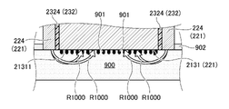
- FIG. 10 shows the state immediately after the head portion 20 of the electric shaver 1 contacts the target portion 900.
- the high frequency voltage is applied to the target site 900 with the frame portion 224 as the outer electrode 221 and the contact surface portion 21311 as the inner electrode 221 .
- the path of such a high-frequency current is schematically indicated by an arrow R1000.
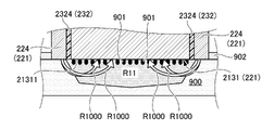
- FIG. 11 shows the state after the head portion 20 of the electric shaver 1 has come into contact with the target portion 900 and the heating means 22 has been activated.
- the heated range is schematically indicated by a hatched region R11.
- the heating effect of the heating means 22 can be efficiently imparted over a relatively wide range of the target site.
- the electric heating effect based on the high-frequency current by the heating means 22 is less likely to cause drying of the skin than external heating such as a heater or light irradiation, and an effect of keeping the skin moist can be expected.
- the electric shaver 1 configured to heat the target portion 900 can efficiently apply a heating effect over a relatively wide range of the target portion 900 . Thereby, the hair removal efficiency can be effectively enhanced.
- one of the pair of electrodes 221 of the heating means 22 is realized by the outer blade portion 2131 (contact surface portion 21311), and the other of the pair of electrodes 221 is realized by the frame portion. 224, the heating means 22 can be realized with a relatively small number of parts. That is, by using the outer blade portion 2131 which is an existing component, it is possible to reduce the number of additional components for providing the heating means 22 .
- one of the pair of electrodes 221 of the heating means 22 is implemented by the entire contact surface portion 21311, but may be implemented by only a part of the contact surface portion 21311. .
- the other of the pair of electrodes 221 of the heating means 22 is implemented by the entire frame 224, but may be implemented by a part of the frame 224.
- the frame portion 224 may be formed by insert molding with resin and metal material. In this case, the portion of metal material forms the electrode 221 .
- the light irradiation section 70 described above with reference to FIG. 1 may be provided around the cutter unit 21, that is, in the frame section 224.
- the light irradiation section 70 may be provided outside the frame section 224 .
- the light irradiation section 70 may be provided at the end of the peripheral wall 2324 on the positive side in the Y direction.
- the frame portion 224 may be provided with a film heater 240 as schematically shown in the plan view of FIG. 12 as another heating means 22.
- the film heater 240 may be arranged on the frame portion 224 in a manner that does not hinder the function of the frame portion 224 as the electrode 221 .
- the pair of electrodes 221 may be eliminated and the film heater 240 may function as the sole heating means 22 .
- the wiring from the battery 12 or the controller 300 may be as described above with reference to FIG.
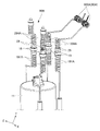
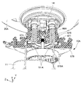
- FIGS. 13 and 14 an example of the wiring structure 90 in the head section 20 applicable to the examples shown in FIGS. 6 to 8 will be described.
- FIG. 14 shows a state in which one of the cutter units 21 is removed.
- FIG. 13 and 14 are diagrams showing an example of the wiring structure 90 in the head section 20.
- FIG. 13 and 14 are diagrams showing an example of the wiring structure 90 in the head section 20.
- the wiring structure 90 is an electrical connection structure that realizes electrical connection between the pair of electrical contacts 29 and the pair of electrodes 221 shown in FIG. has a contact holding portion 290 for holding the .
- the contact holding portion 290 can be attached to and detached from a contact holding portion (not shown) on the main body 10 side. In this case, a magnetic contact using a magnet may be realized.
- the contact holding portion 290 is attached to the contact holding portion on the main body 10 side, the pair of electrical contacts 29 are electrically connected to the pair of electrical contacts 19 (see FIG. 2).
- the wiring structure 90 includes a first wiring 91 (an example of wiring) whose one end is joined to one of the pair of electrical contacts 29 and a second wiring 92 whose one end is joined to the other of the pair of electrical contacts 29 .
- the other end of the first wiring 91 is joined to one of the pair of electrodes 221
- the other end of the second wiring 92 is joined to the other of the pair of electrodes 221 .
- the first wiring 91 includes a first lead-out portion 910 and two first bridging portions 911 and 912 (an example of wiring portions).
- the first drawer part 910 is passed from the outside to the inside of the main holder part 231 .
- the first lead-out portion 910 has one end on the outside of the main holder portion 231 joined to one of the pair of electrical contacts 29 as shown in FIG. 14, and the other end on the inside as shown in FIG. It is joined to the outer blade portion 2131 of the cutter unit 21(1).
- the first drawn-out portion 910 may be joined to the lower side (Y-direction negative side) of the outer blade portion 2131 .
- the first transition portion 911 has one end joined to the outer blade portion 2131 of one cutter unit 21(1) and the other end connected to the outer edge of the other cutter unit 21(2). It is joined to the blade portion 2131 . In this manner, the outer blade portion 2131 of one cutter unit 21(1) and the outer blade portion 2131 of the other cutter unit 21(2) are electrically connected via the first transition portion 911. be done.
- the first transition portion 912 has one end joined to the outer blade portion 2131 of another cutter unit 21 (2), and the other end connected to the other cutter unit 21 ( 3) is joined to the outer blade portion 2131 .
- the outer blade portion 2131 of another cutter unit 21(2) and the outer blade portion 2131 of still another cutter unit 21(3) are connected via the first transition portion 912. electrically connected.
- the first wiring 91 connects one of the pair of electrical contacts 29 and one of the pair of electrodes 221 via the first lead-out portion 910 and the two first bridging portions 911 and 912 to the three electrodes 221 . It is electrically connected to each outer blade portion 2131 of the cutter unit 21 . Thereby, the three cutter units 21 forming one of the pair of electrodes 221 can be simultaneously energized via one of the pair of electrical contacts 29 .
- the second wiring 92 includes a second lead-out portion 920 and two second bridging portions 921 and 922 .
- the second drawer part 920 is passed from the outside to the inside of the main holder part 231 .
- the second lead-out portion 920 has one end on the outside of the main holder portion 231 joined to one of the pair of electrical contacts 29 as shown in FIG. 14, and the other end on the inside as shown in FIG. It is joined to the frame portion 224 around the cutter unit 21(3).
- the second lead-out portion 920 may be joined to the lower side of the frame portion 224 (negative side in the Y direction).
- the second transition portion 921 has one end joined to the frame portion 224 around one cutter unit 21(3) and the other end joined to the other one cutter unit 21(2). It is joined to the frame portion 224 . In this manner, the frame portion 224 around one cutter unit 21(3) and the frame portion 224 around the other cutter unit 21(2) are electrically connected via the second transition portion 921. be done.
- the second bridge portion 922 has one end joined to a frame portion 224 around another cutter unit 21 (2), and the other end connected to a further cutter unit 21 (2). 1) It is joined to the surrounding frame portion 224 . In this way, the frame portion 224 around another cutter unit 21(2) and the frame portion 224 around still another cutter unit 21(1) are connected via the second transition portion 922. electrically connected.
- the second wiring 92 connects the other of the pair of electrical contacts 29 and the other of the pair of electrodes 221 via the second lead-out portion 920 and the two second bridging portions 921 and 922 to the three electrodes. It is electrically connected to each of the frame portions 224 . Thereby, the three frame portions 224 forming the other of the pair of electrodes 221 can be simultaneously energized via the other of the pair of electrical contacts 29 .
- each cutter unit 21 is supported so as to be displaceable with respect to the main holder portion 231, and the shape of the target portion 900 is changed when the electric shaver 1 is used. It can be displaced with respect to the main holder portion 231 in response to, for example.
- the first lead-out portion 910 of the first wiring 91 is preferably connected to one of the pair of electrodes 221 even when the cutter unit 21 is displaced with respect to the main holder portion 231.
- the lead-out portion 910 of the first wiring 91 preferably has appropriate looseness and flexibility so as to absorb the displacement of the cutter unit 21 ( 1 ) with respect to the main holder portion 231 .
- the first lead-out portion 910 may be composed of a single wire or stranded wire, a flat cable, a conductive spring, or the like.
- the first crossover portion 911 of the first wiring 91 is preferably displaced relative to the main holder portion 231 when the two cutter units 21 are displaced independently of each other.
- both ends of the first bridging portion 911 are configured to maintain the joint state with one of the pair of electrodes 221 .
- the first crossover portion 911 of the first wiring 91 preferably has appropriate looseness and flexibility so as to absorb independent displacement of the two cutter units 21 with respect to the main holder portion 231 .
- the first crossover portion 911 may be composed of a single wire or stranded wire, a flat cable, a conductive spring, or the like.
- the skin of the target portion 900 can be stably heated. .
- the frame portion 224 is not displaceable with respect to the main holder portion 231, so the second wiring 92 may have a configuration with relatively little slack or low flexibility.
- the pair of electrical contacts 29 on the side of the head portion 20 are held by a contact holding portion 290 separate from the connecting portion between the head portion 20 and the body portion 10.
- the pair of electrical contacts 29 on the head portion 20 side may be provided at the connecting portion between the head portion 20 and the body portion 10 as described above.
- a pair of electrical contacts 29 on the side of the head section 20 may be provided on the held section 2304 of the base section 230 as shown in FIG.
- the first lead-out portion 910 of the first wiring 91 and the second lead-out portion 920 of the second wiring 92 may be led out to the base portion 230 using the rotating shaft portion 2301 or the like.
- a portion of the first lead-out portion 910 of the first wiring 91 and a portion of the second lead-out portion 920 of the second wiring 92 are realized by conductor portions that may be embedded in the base portion 230 by insert molding or the like. good too.
- a portion of the first wiring 91 and a portion of the second wiring 92 may be implemented by conductor portions that may be embedded in the main holder portion 231 by insert molding or the like. .
- the first wiring 91 and/or the second wiring 92 may be composed of stainless steel wires.
- the surfaces of the first wiring 91 and/or the second wiring 92 may be plated with nickel or zinc.
- the first wiring 91 and/or the second wiring 92 are made of stainless steel whose surface is resistant to corrosion due to a passivation film and has high electrical resistance, and is plated with nickel, which has low electrical resistance. can do.
- electrical contacts 19 and/or electrical contacts 29 may similarly be plated on stainless steel.
- the surface material of the first wiring 91 and/or the second wiring 92 and the electrical contact 19 and/or the electrical contact 29 may be the same material such as nickel. Deterioration due to galvanic corrosion of dissimilar metals can be prevented.
- an insulating film may be provided on the surface of the first wiring 91 and the second wiring 92 so as not to cause an electrical short circuit, or the distance between the wirings may be widened.
- a wall may be provided between the wirings to increase the creepage distance and reduce the overall size of the head section 20 .
- the insulation resistance of the first wiring 91 and/or the second wiring 92 may be greater than the insulation resistance between the frame portion 224 and the outer blade portion 2131 .
- the distance may be widened.
- the insulation resistance between the first wiring 91 and the second wiring 92 and between the frame portion 224 and the outer blade portion 2131 is filled with a liquid such as water or a conductive substance such as gel. It is possible to make the current flow more easily.
- the insulation resistance between the first wiring 91 and the second wiring 92 to be 1 megohm or more when dry and 100 ohm or more when filled with gel, the battery 12 can be miniaturized while heating the skin by high frequency. can be ensured.
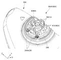
- FIG. 16 is a perspective view of the head portion 20A of the electric shaver 1A of this embodiment, showing the cutter unit 21A and shaver holder 232A in an exploded state.
- FIG. 17 is a perspective view of the head portion 20A of the electric shaver 1A of this embodiment, with one cutter unit 21A and shaver holder 232A removed, and one cutter unit 21A and one shaver holder 232A in cross section. shown visually.
- FIG. 18 is a perspective view of the base 230A of the electric shaver 1A of this embodiment.
- FIG. 19 is an explanatory diagram of the wiring structure 90A of this embodiment, and is a perspective view from the lower surface side of the head portion 20A of the electric shaver 1A of this embodiment. In FIG. 19, the base 230 is shown removed.
- FIG. 19A is a perspective view from below the frame portion 224A, which also shows a portion of the wiring structure 90A.
- FIG. 20 is a perspective view of the electrical connection structure of the electric shaver 1A of this embodiment.
- FIG. 21 is an enlarged perspective view of the features of the shaver holder 232A.
- FIG. 22 is a perspective view showing the arrangement of the light irradiation section 70A and the like of the electric shaver 1A of this embodiment.
- FIG. 23 is an explanatory diagram of a method for removing the cutter unit 21A of the electric shaver 1A of this embodiment.
- FIG. 24 is a perspective view of the cutter unit holding ring 223A of the electric shaver 1A of
- the main holder section 231A of the head section 20A swingably holds the cutter unit 21A and the frame section 224A through the shaver holder 232A.
- the shaver holder 232A rotates the cutter unit 21A so that the cutter unit 21A can swing with respect to the head section 20A, like the shaver holder 232 of the above-described embodiment.
- the main holder portion 231A has a rotating shaft support portion 2314 (see FIG. 17) extending in one direction perpendicular to the rotating shaft portion 2301 of the base portion 230A (an example of the second swing support mechanism). to rotatably support the shaver holder 232A around the rotary shaft support 2314.
- the frame portion 224A is provided on the upper surface of the outer peripheral portion of the shaver holder 232A, unlike the frame portion 224 according to the first embodiment.
- the frame portion 224A may be fixed to the shaver holder 232A by fitting or the like, or may be integrally formed by insert molding or the like.
- the outer blade portion 2131 (contact surface portion 21311) and the frame portion 224A of the cutter unit 21A are connected to the pair of electrodes 221 related to the heating means 22 (an example of the operating portion).
- the head section 20A accommodates a wiring structure 90A that realizes energization of the pair of electrodes 221.
- the wiring structure 90A is an electrical connection structure that realizes electrical connection between the pair of electrical contacts 29 and the pair of electrodes 221 shown in FIG.
- the wiring structure 90A includes a first wiring 91A having one end joined to one of the pair of electrical contacts 29 and a second wiring 92A having one end joined to the other of the pair of electrical contacts 29 .
- the other end of the first wiring 91A is joined to one of the pair of electrodes 221 and the other end of the second wiring 92A is joined to the other of the pair of electrodes 221 .
- the first wiring 91A includes a first lead-out portion 910A and two first transition portions 911A and 912A.
- the first drawer portion 910A is arranged inside the main holder portion 231A (the side facing the base portion 230A).
- the first lead-out portion 910A is joined to a first electrode 291A having one end electrically connected to one of the pair of electrical contacts 29, as shown in FIG.
- the other end of the first drawer portion 910A is electrically connected to the outer blade portion 2131 (see FIG. 17) of the one cutter unit 21A(1).
- the first drawn-out portion 910A is electrically connected to a pressure plate 2134A arranged below the outer blade portion 2131 of the one cutter unit 21A(1) via an energizing spring 94A (described later). good.
- the first transition portion 911A has one end electrically connected to the outer blade portion 2131 of the one cutter unit 21A(1) via an energizing spring 94A (described later), and the other end , is electrically connected to the outer blade portion 2131 of the other cutter unit 21A(2) via a conducting spring 94A (described later).
- the outer blade portion 2131 of one cutter unit 21A(1) and the outer blade portion 2131 of the other cutter unit 21A(2) are electrically connected via the first transition portion 911A. be done.
- one end of the first crossover portion 912A is electrically connected to the outer blade portion 2131 of the other cutter unit 21A(2) via an energizing spring 94A (described later).
- the end is electrically connected to the outer blade portion 2131 of still another cutter unit 21A(3) via an energizing spring 94A (described later).
- the outer blade portion 2131 of another cutter unit 21A(2) and the outer blade portion 2131 of still another cutter unit 21A(3) are connected via the first transition portion 912A. electrically connected.
- the first wiring 91A is connected to each of the outer blade portions of the three cutter units 21A forming one of the pair of electrodes 221 via the first lead-out portion 910A and the two first bridging portions 911A and 912A.
- 2131 is electrically connected to one of the pair of electrical contacts 29 .
- the three cutter units 21A forming one of the pair of electrodes 221 can be energized simultaneously via one of the pair of electrical contacts 29 .
- the second wiring 92A includes a second lead-out portion 920A and two second bridging portions 921A and 922A.
- the second drawer portion 920A is arranged inside the main holder portion 231A (the side facing the base portion 230A).
- the second lead-out portion 920A is joined to a second electrode 292A having one end electrically connected to the other of the pair of electrical contacts 29, as shown in FIG.
- the other end of the second lead-out portion 920A is electrically connected to a frame portion 224A around one cutter unit 21A(3).
- the second lead-out portion 920A is connected to the electrode portion 940 arranged below the frame portion 224A around the one cutter unit 21A(1) via an energizing spring 94B (described later). may be electrically connected to each other.
- one end of the second transition portion 922A is electrically connected to a frame portion 224A around the other cutter unit 21A(2) via an energizing spring 94B (described later).
- the end is electrically connected to a frame portion 224A around still another cutter unit 21A(1) via a conducting spring 94B (described later).
- the frame portion 224A around another cutter unit 21A(2) and the frame portion 224A around still another cutter unit 21A(1) are connected via the second transition portion 922A. electrically connected.
- the second wiring 92A is connected to each of the three frame portions 224A forming the other of the pair of electrodes 221 via the second lead portion 920A and the two second bridging portions 921A and 922A.
- the other of the electrical contacts 29 is electrically connected.
- the three frame portions 224 ⁇ /b>A forming the other of the pair of electrodes 221 can be energized simultaneously via the other of the pair of electrical contacts 29 .
- the first wiring 91A and/or the second wiring 92A may be composed of stainless steel wires as in the first embodiment described above.
- the surfaces of the first wiring 91A and/or the second wiring 92A may be plated with nickel or zinc.
- the first wiring 91A and/or the second wiring 92A is made of stainless steel, which has a passivation film that makes the surface resistant to corrosion and has high electrical resistance, and is plated with nickel, which has low electrical resistance. can do.
- electrical contacts 19 and/or electrical contacts 29 may similarly be plated on stainless steel.
- the surface material of the first wiring 91A and/or the second wiring 92A and the electrical contact 19 and/or the electrical contact 29 may be the same material such as nickel. Deterioration due to galvanic corrosion of dissimilar metals can be prevented.
- an insulating film may be provided on the surface of the first wiring 91A and the second wiring 92A so as not to cause an electrical short circuit, or the distance between the wirings may be widened.
- a wall may be provided between the wirings to increase the creepage distance and reduce the size of the entire head portion 20A.
- the insulation resistance of the first wiring 91A and/or the second wiring 92A may be greater than the insulation resistance between the frame portion 224A and the outer blade portion 2131.
- the distance may be widened.
- the battery 12 can be miniaturized while heating the skin by high frequency. can be ensured.
- the wiring structure 90A of the present embodiment includes conductive springs 94A and 94B (an example of a stretchable conductor element) at the ends of the first bridging portion 911A, the second bridging portion 921A, and the like.
- the conducting springs 94A and 94B are in the form of coil springs, and may be able to expand and contract in the direction along the rotating shaft portion 2301 .
- the conducting spring 94A has one end electrically connected to the outer blade portion 2131 in the cutter unit 21A and the other end electrically connected to the electrical contact 29 .
- the conducting spring 94B has one end electrically connected to the frame portion 224A and the other end electrically connected to the electrical contact 29 via a wiring spring 954A or the like, which will be described later.
- the conducting springs 94A and 94B do not need to be in direct contact with the lower surface of the outer blade portion 2131 and the lower surface of the frame portion 224A in the cutter unit 21A. Just do it.
- the conducting spring 94A may be electrically connected to the outer blade portion 2131 via a conductive pressure plate 2134A, as shown in FIG.
- the conducting spring 94B may be electrically connected to the frame portion 224A via the electrode portion 940 as described above with reference to FIG. 19A.
- the conductive springs 94A and 94B are configured to maintain electrical connection to the outer blade portion 2131 and the frame portion 224A of the cutter unit 21A even when the cutter unit 21A rotates with respect to the main holder portion 231A. and placed.
- the conduction springs 94A and 94B expand and contract correspondingly, thereby energizing the frame portion 224A and the outer blade portion 2131, which are the pair of electrodes 221.
- An electrical connection can be maintained between the springs 94A, 94B.
- the electric contact 29 on the side of the head portion 20A and the paired electrodes 221 can be maintained in a conductive state.
- the wiring structure 90A further includes a conductor torsion spring 950A provided around the opening/closing shaft 2302, as shown in FIGS.
- the torsion springs 950A are provided in pairs, and one end of each is electrically connected to the above-described first electrode 291A and second electrode 292A. 20, the torsion spring 950A has the other end connected to the electrical contact 29 (transmission means 294A to be described later).
- a wiring structure 90A as shown in FIG. 19, substantially all of the wiring structure 90A is arranged inside the head portion 20A (that is, on the side of the base portion 230A of the main holder portion 231A). Therefore, when the head portion 20A is open, as shown in FIG. 18, the wiring structure 90A is substantially not arranged on the base portion 230A.
- a member such as the contact holding portion 290 of the first embodiment as described above with reference to FIG. 14 is not required.
- a wiring structure 90B (partially shown in FIG. 20) may be arranged in the base portion 230A to conduct electricity to the light irradiation portion 70A and the temperature measuring means 72A arranged in the base portion 230A as shown in FIG.
- a cutter unit holding ring 223A is provided on the outer peripheral portion of the cutter unit 21A.
- the cutter unit holding ring 223A has a function of detachably holding the cutter unit 21A with respect to the head portion 20A.
- the cutter unit holding ring 223A holds the cutter unit 21A and the shaver holder 232A from above so that the wiring structure 90A can be easily arranged in the main holder portion 231A. Lock.
- the cutter unit holding ring 223A is arranged on the outer peripheral side of the cutter unit 21A (the outer peripheral side of the cylindrical peripheral wall portion 21312 of the outer blade portion 2131), and holds the cutter unit 21A to the shaver holder 232A from above.
- the cutter unit retaining ring 223A may be press-fitted to the outer peripheral portion of the cutter unit 21A, or may be integrally formed by insert molding. When the cutter unit holding ring 223A is integrated with the cutter unit 21A, attachment and detachment of the cutter unit 21A with respect to the head portion 20A is facilitated.
- the cutter unit 21A when removing the cutter unit 21A for cleaning or replacement, the cutter unit 21A is removed toward the inside of the head portion 20A.
- wires are installed inside the head portion 20A (that is, inside the main holder portion 231A) so that the user does not accidentally touch the cutter unit 21A and the energizing springs 94A and 94B that energize the heating means 22. is doing.
- the cutter unit 21A When the cutter unit 21A is removed from the main holder portion 231A for cleaning or replacement, it should be removed outside the main holder portion 231A where the current-carrying springs 94A and 94B are arranged (toward the base portion 230A), not inside.
- the cutter unit 21A can be removed from the shaver holder 232A (and from the main holder portion 231A accordingly) without opening the main holder portion 231A with respect to the base portion 230A.
- the cutter unit 21A is attached or detached, the user's fingers or the like do not hit the conducting springs 94A and 94B, so that the narrow space inside the head portion 20A can be effectively used for arranging the conducting springs 94A and 94B.
- the above-described skin treatment by energization can be realized while making the entire head portion 20A small and improving usability.
- the cutter unit holding ring 223A has a substantially cylindrical shape and is configured to rotate coaxially with the cutter unit 21A.
- the cutter unit holding ring 223A can also function as a cutter unit attaching/detaching means when removing the cutter unit 21A from the main holder portion 231 for cleaning or replacement of the cutter unit 21A.
- the cutter unit retaining ring 223A has a fixed angle at which the cutter unit 21A is fixed to the shaver holder 232A (and thus the head portion 20A), and an angle at which the cutter unit 21A can be separated from the shaver holder 232A (and thus the head portion 20A). angle with respect to the head portion 20A.
- a groove portion 2231A is provided on the upper side (user's skin side) of the cutter unit holding ring 223A. The groove portion 2231A is configured to be rotatable within an angle range between the fixed angle and the detachment angle.
- the cutter unit attachment/detachment means used when removing the cutter unit for cleaning or replacement is placed close to the cutter unit inside the head so that it can be attached and detached from the inside of the head. (the side facing the base).
- the cutter unit holding ring 223A has a cylindrical shape that rotates coaxially with the cutter unit 21A, and detachably fixes the cutter unit 21A from above the head portion 20A. Further, the cutter unit holding ring 223A is provided with a groove portion 2231A on the outside (upper side) of the head portion 20A, not inside.
- the cutter unit 21A is fixed when the groove portion 2231A is rotated clockwise, and is released when the groove portion 2231A is rotated counterclockwise.
- the cutter unit retaining ring 223A is arranged so that the contact surface portion 21311 of the cutter unit 21A, the upper surface (working surface) of the frame portion 224A, and the cutter unit retaining ring 223A become farther in this order. Because of this arrangement, the groove 2231A of the cutter unit holding ring 223A does not touch the user's skin while the head 20A is in contact with the user's skin.
- the cutter unit 21A As a result, it is possible to prevent the cutter unit 21A from being carelessly attached and detached while enabling a useful action on the skin via the head portion 20A.
- the cutter unit holding ring 223A is cylindrical and thin, the space between the cutter unit 21A and the frame portion 224A can be narrowed. can be maximized. Therefore, it is possible to optimize the effect on the skin while making the head portion 20A small and improving usability.
- the upper surface (working surface) of the frame portion 224A is preferably a gently curved surface that extends from the inner side (the side in contact with the cutter unit holding ring 223A) to the outer side so as to move away from the user's skin. Change.
- a slit 219 extends from the contact surface portion 21311 toward the side of the cutter unit 21A to guide the user's beard into the cutter unit 21A. Slits 219 may be in the form of linear holes for receiving whiskers.
- the contact surface portion 21311 and the upper surface of the frame portion 224A can be applied. Therefore, it is possible to optimize the effect on the skin while making the head portion 20A small and improving usability. More preferably, the step between the contact surface portion 21311 and the upper surface of the frame portion 224A is set to 0.2 mm or more and 2 mm or less. can.
- a cleaning means 50 in the form of a brush for cleaning the head portion 20A is provided.
- a protrusion 52 is provided facing 2231A.
- the cleaning means 50 for cleaning the cutter unit 21A is provided with the protrusion 52 facing the groove 2231A of the cutter unit holding ring 223A.
- the cutter unit 21A can be attached/detached to/from the head portion 20A simply by pressing against the groove portion 2231A and rotating. Therefore, unlike the conventional attachment/detachment means, there is no need for a projection for putting a finger on, and the head can be designed to be small, which improves usability.
- the main holder portion 231A of the head portion 20A which rotatably supports the shaver holder 232A (and the cutter unit 21A and frame portion 224A associated therewith) has a main holder portion 231A as shown in FIGS.
- a recess 206A is provided.
- the recess 206A may have, for example, a V-shaped cross section when viewed from the side.
- the recess 206A is provided between a plurality of shaver holders 232A that are adjacent in a direction perpendicular to the rotation axis of the rotation shaft support 2314. As shown in FIG.
- the concave portions 206A allow the shaver holders 232A to fall down toward the adjacent shaver holders 232A and toward the main holder portion 231A (lower side) between each pair of adjacent shaver holders 232A.
- a stopper portion 2061A for stopping excessive rotation of the shaver holder 232A (and accordingly the cutter unit 21A and the frame portion 224A) may be provided in the concave portion 206A.
- a shaver holder for supporting a plurality of cutter units with respect to the head portion when a shaver holder for supporting a plurality of cutter units with respect to the head portion is provided so that the plurality of cutter units can swing, the cutter units are placed on convex surfaces of the skin such as the cheeks and chin.
- the shape of the shaver holder side was changed so that it hits. That is, generally, the shaver holder is designed so that it becomes thinner toward the adjacent cutter unit and the surface of the adjacent cutter unit becomes concave.
- an electrode for skin treatment for example, the electrode 221 such as the frame portion 224A).
- the electrode 221 can be placed on the thick portion of the shaver holder, the electrode 221 cannot be placed on the thin portion. If the thickness of the shaver holder is increased so that the electrode 221 can be placed on the thin portion, the cutter unit cannot be fitted to the convex surface of the skin, creating a gap that prevents shaving.
- the upper surface of the main holder portion 231A of the head portion 20A is provided with a concave portion 206A on the side adjacent to each of the cutter units 21A so as to fall into the head portion 20A.
- a heating means 22 may be provided on the shaver holder 232A.
- the mechanical connection structure and electrical connection structure between the head portion 20A and the main body portion 10A can also be applied to various skin treatment devices other than the electric shaver 1A (e.g., facial equipment, etc.).
- the wiring structure 90A described above with reference to FIG. 19 and the like can also be applied to various skin treatment devices (for example, a facial device, etc.) other than the electric shaver 1A.
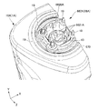
- FIG. 25 is a perspective view showing the connecting portion between the head portion 20A and the body portion 10A of the electric shaver 1A of this embodiment from below.
- FIG. 26 is a perspective view of a connecting portion of the body portion 10A of the electric shaver 1A of this embodiment, and FIG. 26 shows the body portion 10A in a partially cut state.
- FIG. 26A is a perspective view of the connecting portion of the body portion 10A of the electric shaver 1A of this embodiment, and is a perspective view from a different angle from that of FIG.
- FIG. 27 is a perspective view of the connecting portion of the head portion 20A of the electric shaver 1A of this embodiment, and FIG. 27 shows the head portion 20A in a partially cut state.
- FIG. 28 is a perspective view showing the second connecting means 67A.
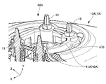
- the head portion 20A is rotatably connected to the body portion 10A by the first connecting means 66A so as to be swingable with respect to the body portion 10A.
- the first connecting means 66A may rotatably connect the head portion 20A to the main body portion 10A, for example, in such a manner that the head portion 20A can rotate about two axes orthogonal to the rotating shaft of the electric motor 11. As shown in FIG.
- the first connecting means 66A includes a connecting portion 662A on the main body portion 10A side and a connected portion 664A on the head portion 20A side.
- the connecting portion 662A has a spherical concave surface 6620A formed on the upper end surface of the shaft member 13 extending from the electric motor 11, as shown in FIG.
- a reduction mechanism (not shown) or the like may be provided between the shaft member 13 and the electric motor 11 .
- the connected portion 664A has a spherical convex surface 6640A formed on the lower end surface of the rotating shaft 14 for driving the cutter unit 21, as shown in FIG.
- the head portion 20A When the head portion 20A is attached to the main body portion 10A, the spherical concave surface 6620A of the connecting portion 662A is fitted into the spherical convex surface 6640A of the connected portion 664A. In this case, the head portion 20A can be rotated with respect to the main body portion 10A through sliding between the spherical concave surface 6620A of the connecting portion 662A and the spherical convex surface 6640A of the connected portion 664A.
- connection between the connecting portion 662A and the connected portion 664A is such that the rotational power from the electric motor 11 is transmitted to the rotating shaft 14 for driving the cutter unit 21 (and accordingly the rotating shaft portion 2301) (that is, so that the relative rotation about the axis of the shaft member 13 is restricted).
- the connecting portion 662A has a non-circular outer shape (three corners extending radially inward with respect to the axis of the shaft member 13) when viewed in the axial direction of the shaft member 13. 6621A) limits the extent of the spherical concave surface 6620A.
- the connected portion 664A has a non-circular outer shape when viewed in the axial direction of the shaft member 13 (three corner portions 6641A are arranged radially inward with respect to the shaft member 13). ) restricts the range of the spherical convex surface 6640A.
- the head portion 20A is rotatable with respect to the main body portion 10A by the second connecting means 67A (an example of the first swing support mechanism) so as to be swingable with respect to the main body portion 10A. concatenated.
- the second connecting means 67A may be formed from two rotating shafts 671, 672 and two bearings 676, 677 orthogonal to each other, as shown in FIG. Note that the rotating shafts 671 and 672 may be orthogonal to the shaft member 13 . In this case, as shown in FIG. 28, the rotating shaft 671 and the bearing 676 allow the head 20A to swing relative to the main body 10A in a direction perpendicular to both the shaft member 13 and the rotating shaft 671. .
- the rotating shaft 672 and the bearing 677 cause the head 20A to swing in a direction perpendicular to both the shaft member 13 and the rotating shaft 672 with respect to the main body 10A.
- the head 20A including the surface (working surface) of the frame portion 224A is supported by the main body portion 10A so as to be swingable in the front, rear, left, and right directions. distance does not change.
- the user does not need to hold the head 20A and the main body 10A separately, and simply holds the main body 10A and lightly touches the head 20A to an approximate position near the skin to be processed, and the complex curved surface of the skin is adjusted to the frame.
- the surface (working surface) of the portion 224A can be reliably applied.
- the user desires strong treatment or stimulation, he/she can apply the main body 10A strongly against the skin without touching the head 20A.
- the main body 10A can be gently applied to the skin.
- the two rotating shafts 671, 672 and the two bearings 676, 677 have a gap of 1 mm in this embodiment in the radial direction about each of the rotating shafts 671, 672 so as to facilitate rotation. good.
- the head 20A is urged in advance toward the skin by a transmission means 191A (a coil spring to be described later). Therefore, the head 20A can move up and down, for example, about 1 mm in the skin direction.
- the transmitting means 121A shrinks within a range of 1 mm to absorb the force without damaging the skin.
- the electrical contact 19 (see FIG. 2) on the main body 10A side includes a transmission means 191A including a coil spring that can expand and contract in the vertical direction (for example, the direction parallel to the axial direction of the shaft member 13).
- the transmission means 191A has one end connected to the body side and the other end forming the electrical contact 19 .
- the electrical contact 19 may be in the form of a conductor piece supported by a coil spring (an example of a stretchable conductor element) forming the transmission means 191A.
- the conductor piece may have a cylindrical or columnar shape, and may be fixedly supported by the coil spring forming the transmission means 191A such that a portion of the conductor piece protrudes from the upper portion of the coil spring.
- the electrical contact 19 is supported vertically movably with respect to the contact holder 670, as shown in FIGS. Specifically, the electrical contact 19 can move up and down with respect to the contact holder 670 with the position where the upper end face abuts the contact holder 670 as the upper limit position.
- the electrical contact 19 is urged upward by the transmission means 191A comprising the coil spring described above. Therefore, when the electrical contact 19 is in the upper limit position, the contact holder 670 is urged upward by the transmission means 191A through the electrical contact 19.
- the contact holder 670 forms part of the second coupling means 67A described above. Specifically, as shown in FIG.
- the contact holder 670 has a rotating shaft 671 and is supported by a bearing 676 of a swing plate 676A attached to the sub-holder 678 side.
- the sub-holder 678 has a rotating shaft 672 orthogonal to the rotating shaft 671 and is supported by a bearing 6776 on the bracket 679 side. Note that the bracket 679 is fixed to the main body portion 10A.
- the second connecting means 67A includes two rotating shafts 671 and 672, but the present invention is not limited to this. It may be realized by other connecting means as long as they can be kept at a distance and supported pivotally. Also, in this embodiment, the swinging mechanism related to the second connecting means 67A is provided on the main body portion 10A side, but may be provided on the head 20A side. In this case, the contact holder 298 on the side of the head 20A holding the electrical contact 29 is fixed to the head 20A, but may be supported so as to be able to swing.
- the electrical contact 29 (see FIG. 2) on the side of the head portion 20A includes a transmission means 294A including a coil spring that can expand and contract in the vertical direction.
- One end (upper end) of the transmission means 294A forms the electrical contact 29 on the head portion 20A side, and the other end (lower end) is a free end.
- the lower end portion (the lower end of the coil spring) of the transmission means 294A is connected to the upper end portion (the electrical contact 19) of the transmission means 191A.
- the electrical contact 19 and the electrical contact 29 are electrically connected by inserting the upper end of the electrical contact 19 in the form of a conductor piece radially inwardly of the coil spring of the transmission means 294A.
- the coil springs of the transmission means 191A and the transmission means 294A expand and contract correspondingly, thereby allowing the head portion 20A and the main body portion 10A to rotate. can maintain an electrical connection between (that is, electrical continuity between electrical contact 19 and electrical contact 29). That is, in the present embodiment, the electrical connection structure is such that the electrical contact 19 on the main body portion 10A side and the electrical contact 29 on the head portion 20A side are connected even when the head portion 20A swings with respect to the main body portion 10A. can maintain electrical connection.
- the first connecting means 66A and the second connecting means 67A for rotatably connecting the head portion 20A to the main body portion 10A (that is, the substantial connecting means between the head portion 20A and the main body portion 10A).
- a first connecting means 66A and a second connecting means 67A) that enable rotation in a manner in which the physical distance does not change, and spring contacts (extendable transmission means 191A and transmission means 294A) arranged in the vicinity thereof allow the head
- the skin treatment can be realized while swinging the unit 20A according to the uneven surface of the user's skin. That is, even if the head portion 20A swings, the electric power supply to the heating means 22 and the like can be continued. can be maintained. Therefore, it is possible to achieve effective skin treatment as described above while improving usability of the hand-held device.
- four pairs of transmission means 191A and transmission means 294A may be provided around the first connection means 66A (and the connection structure 40A, which will be described later).
- another two pairs of transmission means 191A and transmission means 294A may be connected to the wiring structure 90B for the light irradiation section 70A, as shown in FIG. This makes it possible to achieve two combinations of the combination of the positive electrode and the negative electrode for the heating means 22 and the combination of the positive electrode and the negative electrode for the light irradiation section 70A.
- a pair of transmission means 191A and transmission means 294A are provided around the first connection means 66A, or three or more pairs of transmission means 191A and transmission means 294A are provided around the first connection means 66A.
- one set or three or more sets of positive and negative electrodes may be arranged.
- the light irradiator 70A is arranged together with a temperature measuring means 72A such as a thermistor using the central space surrounded by the three cutter units 21A.
- a temperature measuring means 72A such as a thermistor using the central space surrounded by the three cutter units 21A.
- the heating means 22 can be appropriately controlled based on the measurement result by the temperature measuring means 72 .
- the head portion 20A has a connecting structure 40A that connects to the head portion 20A in a detachable manner with respect to the main body portion 10A.
- a connecting structure 40A that connects to the head portion 20A in a detachable manner with respect to the main body portion 10A.
- an attachment with another function for example, attachments for facial equipment.
- Alternative functional attachments may be attached to body portion 10A in a compatible fashion by having electrical contacts 29 similar to head portion 20A.
- the body portion 10A can rotatably and detachably hold the head portion 20A, so that various attachments that can swing and exert various actions on the skin can be used. Wearing (exchange) becomes possible, and convenience is improved.
- the controller 300 of the main body 10A may be able to specify (identify) the type of attached attachment.
- the type of attachment is specified (identified) by magnetic or electrical means such as changing the magnetic resistance value or electrical resistance value related to the electrical connection structure for each type of attachment, or by mechanical connection structure It may be realized by using mechanical means such as changing the shape of the connecting portion according to the type of attachment.
- the control unit 300 of the main unit 10A may specify (identify) the type of attachment in the worn state based on the input information from the user. In either case, the control unit 300 outputs (for example, the number of revolutions of the electric motor 11, optical stimulation, thermal stimulation, vibration stimulation, electrical stimulation, etc.) can be controlled.
- the connecting structure 40A includes a held portion 41A on the head portion 20A side and a holding portion 42A on the main body portion 10A side.
- the held portion 41A may be in the form of a convex claw that may be biased by a plate spring or the like, as shown in FIG. 41A (in the form of a convex claw) may be in the form of a concave claw that can be fitted.
- the head portion 20A can be easily attached to and detached from the main body portion 10A by the connection structure 40A including a fitting structure using claws.
- the lower end of the transmission means 294A on the head portion 20A side is detachably connected to the upper end (electrical contact 19) of the transmission means 191A. That is, when the head portion 20A and the main body portion 10A are separated from each other, the lower other end of the transmission means 294A and the upper end portion of the transmission means 191A are separated from each other, and the electrical contact 19 and electrical contact 29 are in a non-conducting state. Therefore, for example, when the head portion 20A and the main body portion 10A are separated from each other, the electrical contact 29 and the electrical contact 19 are maintained in a connected state by an electric wire or the like. , The electric wire etc. concerning wiring do not become an obstacle, and the convenience improves. In addition, attachment (exchange) of various attachments as described above is facilitated, and convenience is improved.
- the lower other end of the transmission means 294A and the upper end portion of the transmission means 191A are connected to each other. becomes. That is, the electrical contact 19 and the electrical contact 29 are in a conductive state. Therefore, when the head portion 20A and the main body portion 10A are separated from each other, the electric contact 29 and the electric contact 19 are kept connected by an electric wire or the like. can reliably prevent unintended operation (malfunction such as operation of the heating means 22 of the detached head portion 20A).
- control unit 300 may be capable of distinguishing (detecting) the attached state in which the head unit 20A is attached to the main body unit 10A and the non-attached state.
- control section 300 may realize such determination based on the electrical connection state between the electrical contacts 19 and 29 .
- control section 300 may operate the heating means 22 and the like only while the mounting state in which the head section 20A is mounted on the main body section 10A is detected.
- the heating means 22 is disclosed as an example of the action means for applying a specific action to the target portion 900 of the user with which the head unit 20 contacts.
- the action means for applying the specific action to the target site 900 is not limited to the heating means 22 . That is, in place of or in addition to the heating means 22, action means capable of imparting a specific action other than the heating action may be used.
- the means of action may comprise a pair of electrodes similar to the pair of electrodes 221 for generating electrical stimulation at the target site 900 of the user. Again, the working means can operate with the pair of electrodes being powered by the power source in the manner described above.
- the specific effect based on electrical stimulation is a heating effect by high frequency, an effect related to electrical muscle stimulation (EMS: Electrical Muscle Stimulation), an effect related to iontophoresis, an effect related to ion extraction, or any combination thereof.
- EMS is advantageous in that the target region 900 can be tightened and slack care can be performed.
- ion derivation has the advantage of being able to remove pore dirt on the skin at the target site 900
- iontophoresis has the advantage of being able to moisturize the skin at the target site 900 .
- Such a specific action is suitable for skin care after shaving.
- electric energy is supplied from the main body part 10A to the head part 20A via the transmission means 191A and the transmission means 294A, whereby electric heating, vibration,
- the energy to be supplied is not limited to electrical energy.
- Thermal energy or the like may be supplied instead of electrical energy.
- the electrical connection structure realized through the electrical contacts 19 and 29 described above transmits sensor information (electrical signals) from various sensors that may be provided in the head section 20A to the main body section 10A. It may be used as a communication line for supplying.
- the various sensors that may be provided in the head unit 20A include a temperature sensor (for example, the temperature measuring means 72 described in the second embodiment), a humidity sensor, and an image sensor (for example, an image sensor for measuring skin condition, etc.). sensor), etc.
- the electrical connection structure realized through the electrical contacts 19 and 29 described above is not limited to other elements (other than the light irradiation section 70A, other than the light irradiation section 70A) that may be provided in the main body section 10A. element).
- the other element may be a Peltier element, a communication module, or the like.
- the electric shaver 1A is an example of the skin treatment device in the above-described second embodiment (the same applies to the first embodiment), it is also applicable to other skin treatment devices such as facial equipment as described above.
- a head portion corresponding to the head portion 20A may be provided with a plurality of electrodes for applying various output waveforms to the skin instead of or in addition to the cutter unit 21A.
- the electrical connection structure according to Example 2 described above may be applied to the electrical connection structure between the plurality of electrodes and the main body portion 10A.
- some or all of the multiple electrodes may be removably fixed to a holder similar to the shaver holder 232A by a retaining ring similar to the cutter unit retaining ring 223A.
Landscapes
- Health & Medical Sciences (AREA)
- Engineering & Computer Science (AREA)
- Life Sciences & Earth Sciences (AREA)
- Nuclear Medicine, Radiotherapy & Molecular Imaging (AREA)
- Biomedical Technology (AREA)
- Radiology & Medical Imaging (AREA)
- Animal Behavior & Ethology (AREA)
- General Health & Medical Sciences (AREA)
- Public Health (AREA)
- Veterinary Medicine (AREA)
- Oral & Maxillofacial Surgery (AREA)
- Plastic & Reconstructive Surgery (AREA)
- Bioinformatics & Cheminformatics (AREA)
- Mechanical Engineering (AREA)
- Forests & Forestry (AREA)
- Dry Shavers And Clippers (AREA)
Priority Applications (4)
| Application Number | Priority Date | Filing Date | Title |
|---|---|---|---|
| CN202610144143.2A CN121777212A (zh) | 2021-06-07 | 2022-05-11 | 皮肤处理装置 |
| US18/041,018 US20230310846A1 (en) | 2021-06-07 | 2022-05-11 | Skin treatment device |
| EP22819988.1A EP4353429A4 (en) | 2021-06-07 | 2022-05-11 | Skin processing device |
| CN202280005681.3A CN116209552B (zh) | 2021-06-07 | 2022-05-11 | 皮肤处理装置 |
Applications Claiming Priority (2)
| Application Number | Priority Date | Filing Date | Title |
|---|---|---|---|
| JP2021094920A JP7460578B2 (ja) | 2021-06-07 | 2021-06-07 | 電気シェーバ |
| JP2021-094920 | 2021-06-07 |
Publications (1)
| Publication Number | Publication Date |
|---|---|
| WO2022259804A1 true WO2022259804A1 (ja) | 2022-12-15 |
Family
ID=84424853
Family Applications (1)
| Application Number | Title | Priority Date | Filing Date |
|---|---|---|---|
| PCT/JP2022/019968 Ceased WO2022259804A1 (ja) | 2021-06-07 | 2022-05-11 | 肌処理装置 |
Country Status (5)
| Country | Link |
|---|---|
| US (1) | US20230310846A1 (https=) |
| EP (1) | EP4353429A4 (https=) |
| JP (2) | JP7460578B2 (https=) |
| CN (2) | CN116209552B (https=) |
| WO (1) | WO2022259804A1 (https=) |
Families Citing this family (1)
| Publication number | Priority date | Publication date | Assignee | Title |
|---|---|---|---|---|
| EP4212295A1 (en) * | 2022-01-14 | 2023-07-19 | Koninklijke Philips N.V. | Electric shavers |
Citations (7)
| Publication number | Priority date | Publication date | Assignee | Title |
|---|---|---|---|---|
| JP2003310341A (ja) * | 2002-04-23 | 2003-11-05 | Matsushita Electric Works Ltd | 除毛装置 |
| JP2004000432A (ja) * | 2002-04-04 | 2004-01-08 | Vine:Kk | 除毛装置及びトリートメント装置 |
| JP2004254858A (ja) * | 2003-02-25 | 2004-09-16 | Ya Man Ltd | 剃毛装置および毛抜き装置 |
| CN101279449A (zh) * | 2007-04-05 | 2008-10-08 | 超人集团有限公司 | 具有负离子发生器的剃须刀 |
| JP2010510821A (ja) | 2006-11-24 | 2010-04-08 | コーニンクレッカ フィリップス エレクトロニクス エヌ ヴィ | イオン導入デバイス |
| JP2019534739A (ja) * | 2016-09-28 | 2019-12-05 | ブラウン ゲーエムベーハー | 電気シェーバー |
| KR20200017032A (ko) * | 2018-08-08 | 2020-02-18 | 오훈 | 롤러가 장착된 회전식 전기면도기 |
Family Cites Families (14)
| Publication number | Priority date | Publication date | Assignee | Title |
|---|---|---|---|---|
| US20050005453A1 (en) * | 2003-07-07 | 2005-01-13 | Zoltan Egeresi | Water pressure driven wet and dry shaver with beard trimmer, water clean out, and speed control |
| JP2005270120A (ja) * | 2004-03-22 | 2005-10-06 | Kikuboshi:Kk | 顔剃り装置 |
| US7897266B2 (en) * | 2007-02-09 | 2011-03-01 | Rovcal, Inc. | Personal grooming device having a tarnish resistant, hypoallergenic and/or antimicrobial silver alloy coating thereon |
| US7877880B2 (en) * | 2007-08-31 | 2011-02-01 | The Gillette Company | Hand held personal care appliance |
| EP2240105B1 (en) * | 2008-01-17 | 2012-09-26 | Syneron Medical Ltd. | A hair removal apparatus for personal use and the method of using same |
| DE102008032150A1 (de) | 2008-07-08 | 2010-01-14 | Braun Gmbh | Elektrischer Rasierer mit integrierter Kühlung |
| JP2012196380A (ja) * | 2011-03-23 | 2012-10-18 | Panasonic Corp | 光照射型美容装置 |
| JP5791457B2 (ja) | 2011-10-12 | 2015-10-07 | 日立マクセル株式会社 | 体毛処理装置 |
| US9084891B2 (en) * | 2012-02-06 | 2015-07-21 | David Aberizk | Pilomotor effect stimulating device and method |
| US8838232B1 (en) * | 2012-03-12 | 2014-09-16 | Thomas Edward Schwerin | Multifunction electric razor having an electrical stimulator |
| WO2015098427A1 (ja) | 2013-12-27 | 2015-07-02 | ヤーマン株式会社 | 美容器 |
| EP3300863B1 (en) | 2016-09-28 | 2020-06-17 | Braun GmbH | Electric shaver |
| CN108714917A (zh) * | 2018-07-09 | 2018-10-30 | 合肥凯石投资咨询有限公司 | 一种加热剃须刀 |
| EP3978212A1 (en) * | 2020-09-30 | 2022-04-06 | Koninklijke Philips N.V. | Shaving unit and electric shaver comprising a main body and a shaving unit |
-
2021
- 2021-06-07 JP JP2021094920A patent/JP7460578B2/ja active Active
-
2022
- 2022-05-11 US US18/041,018 patent/US20230310846A1/en active Pending
- 2022-05-11 CN CN202280005681.3A patent/CN116209552B/zh active Active
- 2022-05-11 WO PCT/JP2022/019968 patent/WO2022259804A1/ja not_active Ceased
- 2022-05-11 CN CN202610144143.2A patent/CN121777212A/zh active Pending
- 2022-05-11 EP EP22819988.1A patent/EP4353429A4/en active Pending
-
2024
- 2024-03-21 JP JP2024044489A patent/JP7749051B2/ja active Active
Patent Citations (7)
| Publication number | Priority date | Publication date | Assignee | Title |
|---|---|---|---|---|
| JP2004000432A (ja) * | 2002-04-04 | 2004-01-08 | Vine:Kk | 除毛装置及びトリートメント装置 |
| JP2003310341A (ja) * | 2002-04-23 | 2003-11-05 | Matsushita Electric Works Ltd | 除毛装置 |
| JP2004254858A (ja) * | 2003-02-25 | 2004-09-16 | Ya Man Ltd | 剃毛装置および毛抜き装置 |
| JP2010510821A (ja) | 2006-11-24 | 2010-04-08 | コーニンクレッカ フィリップス エレクトロニクス エヌ ヴィ | イオン導入デバイス |
| CN101279449A (zh) * | 2007-04-05 | 2008-10-08 | 超人集团有限公司 | 具有负离子发生器的剃须刀 |
| JP2019534739A (ja) * | 2016-09-28 | 2019-12-05 | ブラウン ゲーエムベーハー | 電気シェーバー |
| KR20200017032A (ko) * | 2018-08-08 | 2020-02-18 | 오훈 | 롤러가 장착된 회전식 전기면도기 |
Non-Patent Citations (1)
| Title |
|---|
| See also references of EP4353429A4 |
Also Published As
| Publication number | Publication date |
|---|---|
| EP4353429A1 (en) | 2024-04-17 |
| CN121777212A (zh) | 2026-04-03 |
| JP2022187098A (ja) | 2022-12-19 |
| US20230310846A1 (en) | 2023-10-05 |
| EP4353429A4 (en) | 2025-06-04 |
| JP7460578B2 (ja) | 2024-04-02 |
| CN116209552A (zh) | 2023-06-02 |
| JP2024061901A (ja) | 2024-05-08 |
| JP7749051B2 (ja) | 2025-10-03 |
| CN116209552B (zh) | 2026-02-17 |
Similar Documents
| Publication | Publication Date | Title |
|---|---|---|
| BRPI0407492B1 (pt) | Utensílio portátil, e, aparelho de barbear de segurança | |
| KR102546342B1 (ko) | 갈바닉 피부 마사지 장치 | |
| JP2019037451A (ja) | 美容器具 | |
| EP2952149A1 (en) | Therapeutic treatment device | |
| EP3978212A1 (en) | Shaving unit and electric shaver comprising a main body and a shaving unit | |
| JP2011041705A (ja) | 美容装置 | |
| JP6628504B2 (ja) | ヘアーアイロン | |
| JP2015029844A (ja) | 美容装置 | |
| WO2022259804A1 (ja) | 肌処理装置 | |
| JP7449976B2 (ja) | 肌処理装置 | |
| CN112336513B (zh) | 美容器具 | |
| JP5925512B2 (ja) | 温熱式の美容器具 | |
| JP2020062401A (ja) | ドライヤー及びドライヤー用アタッチメント | |
| EP4134211A1 (en) | Powering a functional unit and obtaining a measurement signal via a single pair of electrical connection paths | |
| JP2019005642A (ja) | ヘアーアイロン | |
| JP6490968B2 (ja) | 美容装置 | |
| JP2023173373A (ja) | 除毛装置、アタッチメントおよび除毛装置セット | |
| JP7291703B2 (ja) | 美容装置 | |
| JP2013198552A (ja) | 美容器具 | |
| CN219230097U (zh) | 便携温控式手术电凝笔 | |
| JP2016022017A (ja) | 美容装置 | |
| JP5739050B2 (ja) | 美容器具 | |
| JP5174524B2 (ja) | 電気かみそり | |
| JP2013172774A (ja) | 美容器具 | |
| KR20210091398A (ko) | 소형 피부 미용기기 |
Legal Events
| Date | Code | Title | Description |
|---|---|---|---|
| 121 | Ep: the epo has been informed by wipo that ep was designated in this application |
Ref document number: 22819988 Country of ref document: EP Kind code of ref document: A1 |
|
| WWE | Wipo information: entry into national phase |
Ref document number: 2022819988 Country of ref document: EP |
|
| NENP | Non-entry into the national phase |
Ref country code: DE |
|
| ENP | Entry into the national phase |
Ref document number: 2022819988 Country of ref document: EP Effective date: 20240108 |