WO2022254929A1 - アクチュエータ駆動装置 - Google Patents
アクチュエータ駆動装置 Download PDFInfo
- Publication number
- WO2022254929A1 WO2022254929A1 PCT/JP2022/015629 JP2022015629W WO2022254929A1 WO 2022254929 A1 WO2022254929 A1 WO 2022254929A1 JP 2022015629 W JP2022015629 W JP 2022015629W WO 2022254929 A1 WO2022254929 A1 WO 2022254929A1
- Authority
- WO
- WIPO (PCT)
- Prior art keywords
- actuator
- coil
- current
- waveform signal
- movable element
- Prior art date
- Legal status (The legal status is an assumption and is not a legal conclusion. Google has not performed a legal analysis and makes no representation as to the accuracy of the status listed.)
- Ceased
Links
Images


Classifications
-
- H—ELECTRICITY
- H01—ELECTRIC ELEMENTS
- H01F—MAGNETS; INDUCTANCES; TRANSFORMERS; SELECTION OF MATERIALS FOR THEIR MAGNETIC PROPERTIES
- H01F7/00—Magnets
- H01F7/06—Electromagnets; Actuators including electromagnets
- H01F7/08—Electromagnets; Actuators including electromagnets with armatures
- H01F7/18—Circuit arrangements for obtaining desired operating characteristics, e.g. for slow operation, for sequential energisation of windings, for high-speed energisation of windings
-
- H—ELECTRICITY
- H02—GENERATION; CONVERSION OR DISTRIBUTION OF ELECTRIC POWER
- H02P—CONTROL OR REGULATION OF ELECTRIC MOTORS, ELECTRIC GENERATORS OR DYNAMO-ELECTRIC CONVERTERS; CONTROLLING TRANSFORMERS, REACTORS OR CHOKE COILS
- H02P29/00—Arrangements for regulating or controlling electric motors, appropriate for both AC and DC motors
- H02P29/02—Providing protection against overload without automatic interruption of supply
- H02P29/024—Detecting a fault condition, e.g. short circuit, locked rotor, open circuit or loss of load
Definitions
- the present disclosure provides an actuator drive device, an electromagnetic valve device, an electromagnetic contactor, and an electromagnetic brake device.
- Devices such as electromagnetic valve devices, electromagnetic contactors, and electromagnetic brake devices are known that have an actuator element that moves a movable element between two predetermined points by magnetic force generated by current flowing through a coil.
- Actuator elements may not operate normally due to wear, foreign matter, or the like, and it is required to automatically determine abnormalities in their operation.
- Patent Document 1 discloses a device for diagnosing signs of failure of an electromagnetic brake device including a brake disc, an armature, an electromagnetic coil, and the like.
- the device of Patent Document 1 detects a current fluctuation component based on a back electromotive force due to changes in the sliding of the armature among changes in the current flowing through the electromagnetic coil, and detects an armature sliding abnormality from the current fluctuation component based on the back electromotive force. to observe.
- the device of Patent Document 1 measures the number of times the current flowing through the electromagnetic coil drops or the current value in order to observe the sliding abnormality of the armature. In this case, it is necessary to define in advance the conditions for determining that the armature has a sliding abnormality according to the number of drops in the current flowing through the electromagnetic coil and the various current values, which requires a great deal of time and effort. Therefore, it is required to be able to more easily determine the abnormality of the actuator element.
- An actuator drive device includes: an actuator element comprising a coil and a movable element, the actuator element moving the movable element between two predetermined points by a magnetic force generated by a current flowing through the coil; a current detector that measures a first current waveform signal that indicates temporal changes in the current flowing through the coil; a storage device for pre-storing a second current waveform signal indicating a temporal change in the current flowing through the coil when the actuator element is operating normally; a comparison circuit for calculating the difference between the first and second current waveform signals; a control circuit for outputting a control signal indicating that the actuator element is not operating normally when the absolute value of the difference between the first and second current waveform signals exceeds a predetermined threshold value.
- An actuator drive device includes: the current detector measures the first current waveform signal over a predetermined length of time including moments when the voltage applied to the coil transitions between zero and non-zero values; The storage device was measured over the predetermined length of time including the instants at which the voltage applied to the coil transitions between zero and non-zero values during normal operation of the actuator element.
- the second current waveform signal is stored in advance.
- An actuator drive device includes: An alarm device is further provided for generating a visual or audible alarm signal in accordance with the control signal.
- An actuator drive device includes: The actuator drive device further comprises a switch circuit that controls current supply to the coil, The current detector is integrated into the switch circuit.
- the size of the entire device can be reduced.
- a solenoid valve device includes: the actuator driving device; a conduit that is opened and closed by a movable element of the actuator driver.
- An electromagnetic contactor includes the actuator driving device; at least one pair of contacts that are opened and closed by a movable element of the actuator driving device.
- An electromagnetic brake device includes: the actuator driving device; and a brake device driven by the movable element of the actuator drive device.
- abnormality of the actuator element can be determined more easily and reliably than conventionally. Further, according to the actuator drive device according to one aspect of the present disclosure, it is possible to provide an electromagnetic valve device, an electromagnetic contactor, and an electromagnetic brake device that can more easily and reliably determine an abnormality of an actuator element than in the past. can.
- FIG. 1 is a block diagram showing the configuration of an actuator driving device according to a first embodiment
- FIG. 2 is a graph showing an example of a voltage applied to a coil 2 of FIG. 1 and a current flowing through the coil 2
- 3 is a graph explaining the operation of the actuator drive device when the actuator element 10 of FIG. 1 is operating normally
- 4 is a graph for explaining the operation of the actuator driving device when the actuator element 10 of FIG. 1 is malfunctioning
- It is a schematic diagram showing a part of composition of electromagnetic valve device 20 concerning a 2nd embodiment.
- It is a schematic diagram showing a part of composition of electromagnetic contactor 30 concerning a 3rd embodiment.
- FIG. 1 is a block diagram showing the configuration of an actuator driving device according to a first embodiment
- FIG. 2 is a graph showing an example of a voltage applied to a coil 2 of FIG. 1 and a current flowing through the coil 2
- 3 is a graph explaining the operation of the actuator drive device when the actuator element 10 of FIG. 1 is operating normally
- 4
- FIG. 11 is a schematic diagram showing a part of the configuration of an electromagnetic brake device 40 according to a fourth embodiment, and is a cross-sectional view showing a state in which the electromagnetic brake device 40 is in operation.
- FIG. 8 is a cross-sectional view showing a state in which the electromagnetic brake device 40 of FIG. 7 is released;
- FIG. 11 is a block diagram showing the configuration of an actuator driving device according to a fifth embodiment; FIG.
- FIG. 1 is a block diagram showing the configuration of the actuator driving device according to the first embodiment.
- the actuator drive device of FIG. 1 includes an actuator element 10, a current detector 11, a storage device 12, a comparison circuit 13, a control circuit 14, a drive circuit 15, and an alarm device 16.
- the actuator element 10 includes a movable element 1, a coil 2, a spring 3, and a housing 4. At least a part of the movable element 1 is made of a ferromagnetic material, and is held so as to move between two predetermined points (the position indicated by the solid line and the position indicated by the broken line in the example of FIG. 1).
- the movable element 1 is a rod-shaped plunger.
- the coil 2 causes the movable element 1 to move to the solid line position when current is flowing.
- coil 2 is a solenoid coil.
- a spring 3 causes the movable element 1 to move to the dashed position when the coil 2 is not energized.
- the housing 4 accommodates the movable element 1 and the coil 2 inside. As a result, the actuator element 10 moves the movable element 1 between two predetermined points by the magnetic force generated by the current flowing through the coil 2 .
- the current detector 11 is connected to a conductor that supplies current to the coil 2 via a current transformer 11a, and measures a current waveform signal I1 that indicates temporal changes in the current flowing through the coil 2.
- the storage device 12 stores in advance a current waveform signal I0 that indicates temporal changes in the current flowing through the coil 2 when the actuator element 10 is operating normally.
- the current waveform signal I0 pre-stored in the storage device 12 is also called "reference waveform signal I0".
- the comparison circuit 13 calculates the difference between the measured current waveform signal I1 and the reference waveform signal I0.
- the control circuit 14 outputs a control signal indicating that the actuator element 10 is not operating normally when the absolute value of the difference between the measured current waveform signal I1 and the reference waveform signal I0 exceeds a predetermined threshold value. to output
- the drive circuit 15 includes a power supply circuit, a switch circuit, etc., and supplies current to the coil 2 under the control of the control circuit 14 .
- the drive circuit 15 stops the operation of the actuator element 10 according to the control signal output from the control circuit 14 when the actuator element 10 is not operating normally.
- the alarm device 16 generates a visual or auditory alarm signal indicating that the actuator element 10 is not operating normally according to the control signal output from the control circuit 14. Thereby, the user is notified of the abnormality of the actuator element 10 .
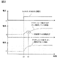
- FIG. 2 is a graph showing an example of the voltage applied to the coil 2 of FIG. 1 and the current flowing through the coil 2.
- the first row in FIG. 2 shows the voltage applied to the coil 2 .
- the second row in FIG. 2 shows the current flowing through the coil 2 when the actuator element 10 is operating correctly.
- the third row in FIG. 2 shows the current flowing through the coil 2 when an abnormality occurs in the actuator element 10 (for example, when the movable element 1 is fixed at the position indicated by the solid line or the position indicated by the broken line in FIG. 1). .
- a predetermined voltage is applied to the coil 2 at time t0 in order to move the movable element 1 from the position indicated by the dashed line in FIG. 1 to the position indicated by the solid line.
- the current flowing through the coil 2 gradually increases after the start of voltage application.
- the movable element 1 is in the position indicated by the dashed line in FIG. 1, the coil 2 has no core, so its inductance is small.
- the movable element 1 is at the position indicated by the solid line in FIG. 1, the magnetic flux of the coil 2 passes through the movable element 1, increasing its inductance. Therefore, if the actuator element 10 operates correctly, as shown in the second row of FIG. 1), it temporarily decreases.
- the movable element 1 is fixed at the solid line position or the broken line position in FIG. do.
- the stroke state of the movable element 1 can be monitored based on the current flowing through the coil 2 by using the characteristics of the solenoid coil whose inductance changes depending on the position of the movable element 1 .
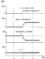
- FIG. 3 is a graph explaining the operation of the actuator driving device when the actuator element 10 of FIG. 1 is operating normally.
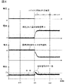
- FIG. 4 is a graph for explaining the operation of the actuator driving device when the actuator element 10 of FIG. 1 is abnormal.
- the first row in FIGS. 3 and 4 shows the voltage applied to the coil 2.
- FIG. 3 and 4 show the current waveform signal I1 measured by the current detector 11.
- FIG. 3 and 4 show an inverted signal of the reference waveform signal I0 stored in the storage device 12.
- FIG. 3 and 4 show the difference between the measured current waveform signal I1 and the reference waveform signal I0.
- the control circuit 14 determines that the actuator element 10 is not operating normally when the absolute value of the difference between the measured current waveform signal I1 and the reference waveform signal I0 exceeds a predetermined threshold value Th. can do.
- the current detector 11 measures the current waveform signal I1 over a predetermined length of time including the instant t11 when the voltage applied to the coil 2 transitions between zero and non-zero values.
- the storage device 12 was measured over a predetermined length of time including the instant t11 when the voltage applied to the coil 2 transitions between zero and non-zero values during normal operation of the actuator element 10.
- a current waveform signal is stored in advance as a reference waveform signal I0.
- the time interval for measuring the current waveform signal I1 or I0 may be set, for example, from t10 to t12, or from t11 to t12.
- the solenoid element 10 may experience an increase in sliding resistance, an increase in the gap between contacts, or an abnormality in stroke due to wear or foreign matter. According to the actuator driving device according to the first embodiment, by calculating the difference between the measured current waveform signal I1 and the reference waveform signal I0, abnormality of the actuator element 10 can be determined more easily and reliably than before. be able to.
- the actuator driving device according to the first embodiment can be applied to electromagnetic valve devices, electromagnetic contactors, electromagnetic brake devices, and the like.
- FIG. 5 is a schematic diagram showing a part of the configuration of the solenoid valve device 20 according to the second embodiment.
- the solenoid valve device 20 includes an actuator element 10A shown in FIG. 5 in place of the actuator element 10 of FIG.
- the actuator element 10A comprises a movable element 1A, a coil 2, a spring 3 and a housing 4.
- the electromagnetic valve device 20 includes a current detector 11, a storage device 12, a comparison circuit 13, a control circuit 14, a drive circuit 15, and an alarm device 16, as in FIG. 1, but illustration thereof is omitted in FIG.
- the coil 2 in FIG. 5 is connected to the current detector 11 and the driving circuit 15 as in FIG.
- a fluid 24 flows inside the conduit 21 .
- Fluid 24 may be a gas such as air or a liquid such as water.
- the conduit 21 comprises a wall 22 with small openings 23 to impede the flow of fluid 24 in part of its flow path.
- the movable element 1A is arranged to close the opening 23 at the dashed line position in FIG.
- the coil 2 moves the movable element 1A to the solid line position when current is flowing.
- the spring 3 moves the movable element 1A to the dashed line position when the coil 2 is not energized.
- the movable element In general, in a solenoid valve device, the movable element cannot operate within the range and speed as designed due to wear of parts or clogging of foreign matter. may not be able to be controlled to the desired value.
- the solenoid valve device 20 according to the second embodiment similarly to the actuator driving device according to the first embodiment, by calculating the difference between the measured current waveform signal I1 and the reference waveform signal I0, Abnormality of the actuator element 10A can be determined more easily and reliably than conventionally.
- the abnormality of the actuator element 10A can be determined more easily and reliably than before. Also, the abnormality of the solenoid valve device 20 can be determined.
- the electromagnetic valve device 20 according to the second embodiment can be applied to, for example, machining devices, welding devices, and cooling devices that supply air or coolant to control panels. Also, the electromagnetic valve device 20 according to the second embodiment can be applied to, for example, a coating device that sprays paint onto an object.
- 3rd Embodiment demonstrates the electromagnetic contactor provided with the actuator drive device which concerns on 1st Embodiment.
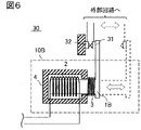
- FIG. 6 is a schematic diagram showing part of the configuration of the electromagnetic contactor 30 according to the third embodiment.
- the electromagnetic contactor 30 includes an actuator element 10B shown in FIG. 6 in place of the actuator element 10 of FIG. 1, and further includes contacts 31 and 32.
- the actuator element 10B comprises a movable element 1B, a coil 2, a spring 3 and a housing 4.
- the electromagnetic contactor 30 includes a current detector 11, a storage device 12, a comparison circuit 13, a control circuit 14, a drive circuit 15, and an alarm device 16, as in FIG. 1, but illustration thereof is omitted in FIG.
- the coil 2 in FIG. 6 is connected to the current detector 11 and the driving circuit 15 as in FIG.
- the contact 31 is fixed to the tip of the movable element 1B, and the contact 32 is provided at a position relatively fixed to the housing 4 of the actuator element 10B.
- the contacts 31 and 32 are connected to an external circuit and are arranged to contact each other when the movable element 1B is in the solid line position.
- the coil 2 moves the movable element 1B to the solid line position when current is flowing.
- a spring 3 causes the movable element 1B to move to the dashed position when the coil 2 is not energized.
- the movable element In general, in an electromagnetic contactor, the movable element cannot operate within the range and speed as designed due to wear of parts or clogging of foreign matter. You may lose control as desired.
- the electromagnetic contactor 30 according to the third embodiment similarly to the actuator driving device according to the first embodiment, by calculating the difference between the measured current waveform signal I1 and the reference waveform signal I0, Abnormalities in the actuator element 10B can be determined more easily and reliably than conventionally.
- the electromagnetic contactor 30 according to the third embodiment can be applied to belt conveyors, for example.
- the electromagnetic contactor 30 can be used to control the on and off of the motor of the belt conveyor.
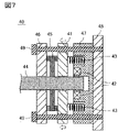
- FIG. 7 is a schematic diagram showing part of the configuration of the electromagnetic brake device 40 according to the fourth embodiment, and is a cross-sectional view showing a state in which the electromagnetic brake device 40 is in operation.
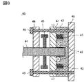
- FIG. 8 is a cross-sectional view showing a state in which the electromagnetic brake device 40 of FIG. 7 is released.
- the electromagnetic brake device 40 includes a movable element 41 , a coil 42 , a spring 43 , a rotating shaft 44 , a brake disk 45 , a receiving plate 46 , a core 47 , a substrate 48 and bolts 49 .
- the receiving plate 46 , core 47 and substrate 48 are fixed together by bolts 49 .
- Movable element 41 is held by bolt 49 between backing plate 46 and core 47 so as to be slidable in the longitudinal direction of bolt 49 .
- the rotating shaft 44 is rotatably held by a receiving plate 46 and a core 47 .
- a brake disc 45 is fixed to the rotating shaft 44 and inserted between the movable element 41 and the receiving plate 46 .
- a movable element 41, a coil 42, and a spring 43 correspond to the movable element 1, the coil 2, and the spring 3 in FIG. 1, respectively, and operate in the same manner as the actuator element 10 in FIG.
- the electromagnetic brake device 40 includes a current detector 11, a storage device 12, a comparison circuit 13, a control circuit 14, a drive circuit 15, and an alarm device 16, as in FIG. omitted.
- the coil 42 in FIGS. 7 and 8 is connected to the current detector 11 and drive circuit 15 as in FIG.
- the spring 43 moves the movable element 41 to the position shown in FIG. 7 when the coil 42 is not energized. As a result, the movable element 41 biases the brake disc 45 against the receiving plate 46 and the rotation of the rotating shaft 44 is prevented. On the other hand, the coil 42 causes the movable element 41 to move to the position of FIG. 8 when current is flowing. As a result, the brake disc 45 is released between the movable element 41 and the receiving plate 46, allowing the rotary shaft 44 to rotate freely.
- the movable element 41, the brake disc 45, and the receiving plate 46 are also collectively referred to as "brake device”.
- the movable element In general, in an electromagnetic brake device, the movable element cannot operate within the range and speed as designed due to wear of parts or clogging of foreign matter. You may not be able to stop properly.
- the electromagnetic brake device 40 according to the fourth embodiment similarly to the actuator drive device according to the first embodiment, by calculating the difference between the measured current waveform signal I1 and the reference waveform signal I0, Abnormalities in the electromagnetic brake device 40 can be determined more easily and reliably than conventionally.
- the electromagnetic brake device 40 according to the fourth embodiment can be applied to devices such as elevators, robot arms, and Automated Guided Vehicles (AGV), for example.
- the electromagnetic brake device 40 according to the fourth embodiment may be configured to stop motors included in these devices.
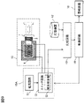
- FIG. 9 is a block diagram showing the configuration of an actuator driving device according to the fifth embodiment.
- the actuator drive device of FIG. 9 includes a drive circuit 15A instead of the current detector 11 and drive circuit 15 of FIG.
- the drive circuit 15A includes a power supply circuit 51 and a switch circuit 52.
- the switch circuit 52 selectively supplies the current supplied from the power supply circuit 51 to the coil 2 under the control of the control circuit 14 .
- Switch circuit 52 comprises, for example, a solid state relay.
- the switch circuit 52 is integrated with a current detector 53 that measures a current waveform signal I1 indicating a temporal change in the current flowing through the coil 2 .
- the control circuit 14 acquires the measured current waveform signal I1 from the current detector 53 .
- the abnormality of the actuator element 10 can be determined.
- the solenoid valve device 20 that closes the flow path when no current is flowing through the coil 2 and opens the flow path when the current is flowing through the coil 2 has been described.
- the driving device can also be applied to a solenoid valve device that closes the flow path when the coil 2 is energized and opens the flow path when the coil 2 is not energized.
- the electromagnetic contactor 30 that turns off when no current is flowing through the coil 2 and turns on when current is flowing through the coil 2 has been described. It can also be applied to an electromagnetic contactor that turns off when current is flowing through the coil 2 and turns on when no current is flowing through the coil 2 .
- the electromagnetic brake device 40 that stops rotation of the rotating shaft 44 when no current is flowing through the coil 2 and rotates the rotating shaft 44 when current is flowing through the coil 2 has been described.
- the actuator drive device according to the embodiment is also an electromagnetic brake device that stops rotation of the rotating shaft 44 when current is flowing through the coil 2 and rotates the rotating shaft 44 when current is not flowing through the coil 2. Applicable.
- the actuator drive device, the electromagnetic valve device, the electromagnetic contactor, and the electromagnetic brake device according to each aspect of the present disclosure may be expressed as follows.
- An actuator drive device includes an actuator element 10, a current detector 11, a storage device 12, a comparison circuit 13, and a control circuit 14.
- the actuator element 10 includes a coil 2 and a movable element 1 , and moves the movable element 1 between two predetermined points by magnetic force generated by current flowing through the coil 2 .
- a current detector 11 measures a first current waveform signal that indicates temporal changes in the current flowing through the coil 2 .
- the storage device 12 pre-stores a second current waveform signal indicating temporal changes in the current flowing through the coil 2 when the actuator element 10 is operating normally.
- Comparator circuit 13 calculates the difference between the first and second current waveform signals.
- the control circuit 14 outputs a control signal indicating that the actuator element 10 is not operating normally when the absolute value of the difference between the first and second current waveform signals exceeds a predetermined threshold.
- an actuator driver wherein the current detector 11 detects the first current for a predetermined length of time including the moment the voltage applied to the coil 2 transitions between zero and non-zero values. Measure a waveform signal.
- the storage device 12 stores the values measured over a predetermined length of time including the instants at which the voltage applied to the coil 2 transitions between zero and non-zero values during normal operation of the actuator element 10 . 2 current waveform signals are stored in advance.
- the actuator drive device further includes an alarm device 16 that generates a visual or auditory alarm signal according to the control signal.
- the actuator drive device further includes a switch circuit 52 that controls current supply to the coil 2 .
- the actuator driver comprises a current detector 53 integrated in the switch circuit 52 .
- a solenoid valve device includes the actuator drive device described above and a conduit 21 that is opened and closed by a movable element 1A of the actuator drive device.
- An electromagnetic contactor includes the actuator driving device described above and at least a pair of contacts 31 and 32 that are opened and closed by the movable element 1B of the actuator driving device.
- An electromagnetic brake device includes the actuator drive device described above and a brake device driven by the movable element 41 of the actuator drive device.
- An actuator drive device is applicable to any device that includes an actuator element. Deterioration of the actuator element can be determined to determine deterioration of the device, which is effective in reducing opportunity loss.
Landscapes
- Engineering & Computer Science (AREA)
- Power Engineering (AREA)
- Physics & Mathematics (AREA)
- Electromagnetism (AREA)
- Braking Arrangements (AREA)
- Control Of Electric Motors In General (AREA)
- Valves And Accessory Devices For Braking Systems (AREA)
- Magnetically Actuated Valves (AREA)
- Regulating Braking Force (AREA)
Applications Claiming Priority (2)
| Application Number | Priority Date | Filing Date | Title |
|---|---|---|---|
| JP2021-092455 | 2021-06-01 | ||
| JP2021092455A JP7663026B2 (ja) | 2021-06-01 | 2021-06-01 | アクチュエータ駆動装置、電磁弁装置、電磁接触器、及び電磁ブレーキ装置 |
Publications (1)
| Publication Number | Publication Date |
|---|---|
| WO2022254929A1 true WO2022254929A1 (ja) | 2022-12-08 |
Family
ID=84322973
Family Applications (1)
| Application Number | Title | Priority Date | Filing Date |
|---|---|---|---|
| PCT/JP2022/015629 Ceased WO2022254929A1 (ja) | 2021-06-01 | 2022-03-29 | アクチュエータ駆動装置 |
Country Status (3)
| Country | Link |
|---|---|
| JP (1) | JP7663026B2 (enExample) |
| TW (1) | TWI856302B (enExample) |
| WO (1) | WO2022254929A1 (enExample) |
Citations (6)
| Publication number | Priority date | Publication date | Assignee | Title |
|---|---|---|---|---|
| JPH07194175A (ja) * | 1993-12-28 | 1995-07-28 | Nippondenso Co Ltd | リニアソレノイドの駆動装置 |
| JP2009089072A (ja) * | 2007-09-28 | 2009-04-23 | Hitachi Ltd | 電磁負荷装置の制御装置 |
| JP3166788U (ja) * | 2011-01-07 | 2011-03-24 | 株式会社 アイチメンテナンス | 昇降機の診断装置 |
| US20140129159A1 (en) * | 2012-11-05 | 2014-05-08 | Siemens Industry, Inc. | Solenoid status determination methods and systems |
| JP6368007B1 (ja) * | 2017-05-26 | 2018-08-01 | 東芝エレベータ株式会社 | ブレーキ故障予兆診断装置 |
| US20200072892A1 (en) * | 2018-08-31 | 2020-03-05 | Eaton Intelligent Power Limited | System and method for spool fault detection of solenoid valves using electrical signature |
Family Cites Families (1)
| Publication number | Priority date | Publication date | Assignee | Title |
|---|---|---|---|---|
| DE102008029312B3 (de) * | 2008-06-20 | 2009-12-24 | Knorr-Bremse Systeme für Schienenfahrzeuge GmbH | Verfahren zur Wirküberwachung von Schienenbremsen |
-
2021
- 2021-06-01 JP JP2021092455A patent/JP7663026B2/ja active Active
-
2022
- 2022-03-25 TW TW111111218A patent/TWI856302B/zh active
- 2022-03-29 WO PCT/JP2022/015629 patent/WO2022254929A1/ja not_active Ceased
Patent Citations (6)
| Publication number | Priority date | Publication date | Assignee | Title |
|---|---|---|---|---|
| JPH07194175A (ja) * | 1993-12-28 | 1995-07-28 | Nippondenso Co Ltd | リニアソレノイドの駆動装置 |
| JP2009089072A (ja) * | 2007-09-28 | 2009-04-23 | Hitachi Ltd | 電磁負荷装置の制御装置 |
| JP3166788U (ja) * | 2011-01-07 | 2011-03-24 | 株式会社 アイチメンテナンス | 昇降機の診断装置 |
| US20140129159A1 (en) * | 2012-11-05 | 2014-05-08 | Siemens Industry, Inc. | Solenoid status determination methods and systems |
| JP6368007B1 (ja) * | 2017-05-26 | 2018-08-01 | 東芝エレベータ株式会社 | ブレーキ故障予兆診断装置 |
| US20200072892A1 (en) * | 2018-08-31 | 2020-03-05 | Eaton Intelligent Power Limited | System and method for spool fault detection of solenoid valves using electrical signature |
Also Published As
| Publication number | Publication date |
|---|---|
| TWI856302B (zh) | 2024-09-21 |
| JP7663026B2 (ja) | 2025-04-16 |
| TW202248111A (zh) | 2022-12-16 |
| JP2022184535A (ja) | 2022-12-13 |
Similar Documents
| Publication | Publication Date | Title |
|---|---|---|
| US11569017B2 (en) | Diagnostic device and method for solenoid valves | |
| JP4685803B2 (ja) | エレベーターブレーキ制御装置 | |
| KR102171954B1 (ko) | 로봇 제어 장치 및 이 제어 장치를 구비한 로봇 | |
| US11693436B2 (en) | Control systems for valve actuators, valve actuators and related systems and methods | |
| US20020069697A1 (en) | Method for testing the brake of an electric motor | |
| CN101900152A (zh) | 以电子方式确定阀门系统的磨损状态的方法及阀门系统 | |
| EP1736680B1 (en) | Electro-mechanical brake | |
| WO2022254929A1 (ja) | アクチュエータ駆動装置 | |
| CN113366252B (zh) | 气动电磁阀、具有电磁阀的现场设备和气动电磁阀的故障诊断方法 | |
| JP2021196001A (ja) | 流量調整弁 | |
| JPH11101359A (ja) | 電動遮断弁 | |
| KR102060097B1 (ko) | 스프링 리턴 스로틀 액추에이터, 스프링 리턴 스로틀 액추에이터의 제어 방법 및 스로틀 어셈블리 | |
| CN108352242A (zh) | 用于监测电磁执行器的运行情况的控制单元和方法 | |
| JP4009676B2 (ja) | 電磁弁の作動モニタリング方法及びその装置 | |
| US11901121B2 (en) | Electronic safety actuator and method of condition or state detection | |
| US11269017B2 (en) | Diagnostic for pulsed solenoid I/P functionality | |
| US20240229968A9 (en) | Method for compensating for tolerances, play and elasticity in a motor-driven hydraulic valve | |
| US11499341B2 (en) | Electrical assembly | |
| JP2022184535A5 (enExample) | ||
| JP2009212024A (ja) | 開閉装置 | |
| JPH0142388B2 (enExample) | ||
| CN121001920A (zh) | 操作单元、用于测试磁流变制动器的功能性的方法、计算机程序产品以及线控转向式系统 | |
| CN121001919A (zh) | 操作单元、用于磁流变制动器的功能检查的方法、计算机程序产品及线控转向系统 | |
| HK1120778B (en) | Brake control device for elevator |
Legal Events
| Date | Code | Title | Description |
|---|---|---|---|
| 121 | Ep: the epo has been informed by wipo that ep was designated in this application |
Ref document number: 22815686 Country of ref document: EP Kind code of ref document: A1 |
|
| NENP | Non-entry into the national phase |
Ref country code: DE |
|
| 122 | Ep: pct application non-entry in european phase |
Ref document number: 22815686 Country of ref document: EP Kind code of ref document: A1 |