WO2022250121A1 - レンズユニット及び撮像装置 - Google Patents
レンズユニット及び撮像装置 Download PDFInfo
- Publication number
- WO2022250121A1 WO2022250121A1 PCT/JP2022/021645 JP2022021645W WO2022250121A1 WO 2022250121 A1 WO2022250121 A1 WO 2022250121A1 JP 2022021645 W JP2022021645 W JP 2022021645W WO 2022250121 A1 WO2022250121 A1 WO 2022250121A1
- Authority
- WO
- WIPO (PCT)
- Prior art keywords
- lens
- temperature
- optical axis
- lens barrel
- direction along
- Prior art date
- Legal status (The legal status is an assumption and is not a legal conclusion. Google has not performed a legal analysis and makes no representation as to the accuracy of the status listed.)
- Ceased
Links
Images




Classifications
-
- H—ELECTRICITY
- H04—ELECTRIC COMMUNICATION TECHNIQUE
- H04N—PICTORIAL COMMUNICATION, e.g. TELEVISION
- H04N23/00—Cameras or camera modules comprising electronic image sensors; Control thereof
- H04N23/50—Constructional details
- H04N23/55—Optical parts specially adapted for electronic image sensors; Mounting thereof
-
- G—PHYSICS
- G02—OPTICS
- G02B—OPTICAL ELEMENTS, SYSTEMS OR APPARATUS
- G02B7/00—Mountings, adjusting means, or light-tight connections, for optical elements
- G02B7/02—Mountings, adjusting means, or light-tight connections, for optical elements for lenses
-
- G—PHYSICS
- G02—OPTICS
- G02B—OPTICAL ELEMENTS, SYSTEMS OR APPARATUS
- G02B7/00—Mountings, adjusting means, or light-tight connections, for optical elements
- G02B7/02—Mountings, adjusting means, or light-tight connections, for optical elements for lenses
- G02B7/021—Mountings, adjusting means, or light-tight connections, for optical elements for lenses for more than one lens
-
- G—PHYSICS
- G02—OPTICS
- G02B—OPTICAL ELEMENTS, SYSTEMS OR APPARATUS
- G02B7/00—Mountings, adjusting means, or light-tight connections, for optical elements
- G02B7/02—Mountings, adjusting means, or light-tight connections, for optical elements for lenses
- G02B7/028—Mountings, adjusting means, or light-tight connections, for optical elements for lenses with means for compensating for changes in temperature or for controlling the temperature; thermal stabilisation
-
- G—PHYSICS
- G02—OPTICS
- G02B—OPTICAL ELEMENTS, SYSTEMS OR APPARATUS
- G02B7/00—Mountings, adjusting means, or light-tight connections, for optical elements
- G02B7/02—Mountings, adjusting means, or light-tight connections, for optical elements for lenses
- G02B7/04—Mountings, adjusting means, or light-tight connections, for optical elements for lenses with mechanism for focusing or varying magnification
-
- H—ELECTRICITY
- H04—ELECTRIC COMMUNICATION TECHNIQUE
- H04N—PICTORIAL COMMUNICATION, e.g. TELEVISION
- H04N23/00—Cameras or camera modules comprising electronic image sensors; Control thereof
- H04N23/50—Constructional details
- H04N23/54—Mounting of pick-up tubes, electronic image sensors, deviation or focusing coils
Definitions
- the present disclosure relates to lens units and imaging devices.
- Patent Document 1 An optical sensor having a lens is known (see Patent Document 1, for example).
- a lens unit includes a lens having an optical axis, a lens frame that holds the lens, a lens barrel, and a temperature correction member.
- the lens barrel has a central axis along the optical axis, accommodates the lens frame on an inner peripheral side, and is configured to be connectable to a substrate on which an imaging device is mounted.
- the temperature compensating member has a first portion and a second portion spaced apart from each other in a direction along the optical axis.
- the temperature correction member contacts the lens barrel at the first portion and contacts the lens frame at the second portion.
- the lens frame is connected to the lens barrel via the temperature compensation member, so that when the length of the temperature compensation member in the direction along the optical axis changes, the lens frame is connected to the lens barrel.
- the length per unit temperature in the direction along the optical axis of the portion from the first portion to the second portion of the temperature correction member is determined by the first portion of the temperature correction member in the lens barrel.
- the portion located on the side connected to the substrate rather than the contact portion differs from the length per unit temperature that extends in the direction along the optical axis.
- An imaging device includes a lens unit and a substrate on which an imaging element is mounted.
- the lens unit includes a lens having an optical axis, a lens frame that holds the lens, a lens barrel, and a temperature correction member.
- the lens barrel has a central axis along the optical axis, accommodates the lens frame on an inner peripheral side, and is configured to be connectable to a substrate on which an imaging device is mounted.
- the temperature compensating member has a first portion and a second portion spaced apart from each other in a direction along the optical axis. The temperature correction member contacts the lens barrel at the first portion and contacts the lens frame at the second portion.
- the lens frame is connected to the lens barrel via the temperature compensation member, so that when the length of the temperature compensation member in the direction along the optical axis changes, the lens frame is connected to the lens barrel. It is configured to be movable in the direction along the optical axis.
- the length per unit temperature in the direction along the optical axis of the portion from the first portion to the second portion of the temperature correction member is determined by the first portion of the temperature correction member in the lens barrel.
- the portion located on the side connected to the substrate rather than the contact portion differs from the length per unit temperature that extends in the direction along the optical axis.
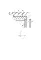
- FIG. 1 is a cross-sectional view showing a configuration example of an imaging device according to an embodiment
- FIG. FIG. 2 is an enlarged view of a portion enclosed by a dashed line in FIG. 1
- FIG. 10 is a diagram showing another configuration example of the temperature adjustment member; It is a figure which shows the structural example containing two lenses. It is a figure which shows the structural example from which the connection direction of a temperature control member differs.
- an imaging device 1 includes a lens unit 10 and an imaging device 80 .
- the lens unit 10 includes a lens 20 , a lens frame 30 , a lens barrel 40 and a temperature correction member 50 .
- the lens 20 has an optical axis 20A connecting a lens center 20C and a focal point 20F. It is assumed that the optical axis 20A extends along the Z-axis direction.
- Light from the subject of the imaging device 1 enters the lens 20 from the opposite side of the focal point 20F.
- Light from a subject is imaged in a focal plane including focal point 20F.
- the distance from the lens center 20C to the focal point 20F is represented as focal length F.
- the lens frame 30 holds the lens 20.
- the lens barrel 40 is configured in a cylindrical shape having a central axis along the optical axis 20A, and accommodates the lens 20 and the lens frame 30 on the inner peripheral side of the cylindrical configuration.
- the temperature correction member 50 connects the lens frame 30 and the lens barrel 40 .
- the temperature correction member 50 has a first portion 51 that contacts the lens barrel 40 and a second portion 52 that contacts the lens frame 30 .
- the first portion 51 and the second portion 52 are positioned apart from each other in the direction along the optical axis 20A.
- the temperature correction member 50 is fixed to the lens barrel 40 at the first portion 51 and fixed to the lens frame 30 at the second portion 52 .
- the temperature correction member 50 defines the positional relationship between the lens barrel 40 and the lens frame 30 by connecting the lens barrel 40 and the lens frame 30 .
- the temperature correction member 50 defines the distance in the Z-axis direction between the position where the lens barrel 40 contacts the first portion 51 and the position where the lens frame 30 contacts the second portion 52 .
- D represents the distance in the Z-axis direction between the position where the lens barrel 40 contacts the first portion 51 and the position where the lens frame 30 contacts the second portion 52 .
- the lens frame 30 is connected to the lens barrel 40 via the temperature correction member 50 .
- the lens frame 30 moves in the Z-axis direction with respect to the lens barrel 40 by changing the length of the temperature correction member 50 in the Z-axis direction. That is, the lens frame 30 is configured to be movable in the Z-axis direction with respect to the lens barrel 40 .
- the first portion 51 and the second portion 52 are configured as surfaces along the XY plane. That is, at least one of the first portion 51 and the second portion 52 may be configured as a plane that intersects the Z-axis direction corresponding to the direction of the optical axis 20A. D represents the distance between the surface corresponding to the first portion 51 and the surface corresponding to the second portion 52 .
- the first portion 51 and the second portion 52 are configured as surfaces along the YZ plane. That is, the first portion 51 and the second portion 52 may be configured as surfaces parallel to the Z-axis direction corresponding to the direction of the optical axis 20A (surfaces that do not intersect the Z-axis direction).
- D represents the distance in the Z-axis direction between the end of the first portion 51 on the positive side of the Z-axis and the end of the second portion 52 on the negative side of the Z-axis.
- the imaging device 80 is mounted on the substrate 82 .
- the imaging device 80 is arranged so that the focal point 20F of the lens 20 is positioned on the imaging plane of the imaging device 80 .
- the imaging device 80 is arranged such that its imaging plane is separated from the lens center 20C by the focal length F.
- the imaging device 80 can capture an image that is in focus.
- the lens barrel 40 is configured to be connectable to the substrate 82 .
- the positional relationship between the lens 20 and the imaging device 80 is defined by connecting the lens barrel 40 to the substrate 82 .
- the focal length F of the lens 20 changes.
- the higher the temperature the longer the focal length F of lens 20 may be.
- the higher the temperature the shorter the focal length F of the lens 20 may be.
- the focal length F may change due to deformation of the lens 20 itself in response to temperature changes.
- the focal length F may change due to changes in the refractive index of the material forming the lens 20 in response to temperature changes.
- the focal length F may change based on various factors other than the illustrated factors in response to temperature changes.
- the focal length F changes when the temperature changes from the predetermined temperature.
- the focal point 20F is shifted from the imaging plane in the Z-axis direction.
- A represents the distance in the Z-axis direction from the portion of the lens barrel 40 in contact with the first portion 51 of the temperature correction member 50 to the imaging surface of the imaging device 80 .
- B represents the distance in the Z-axis direction from the portion of the lens barrel 40 in contact with the first portion 51 of the temperature correction member 50 to the lens center 20C of the lens 20 .
- the state of the imaging apparatus 1 is such that the focal point 20F is located on the imaging surface of the imaging device 80.
- the lens unit 10 may be configured so that the focal point 20F of the lens 20 is aligned with the imaging surface of the imaging device 80 at least at a predetermined temperature when the lens barrel 40 is connected to the substrate 82 .
- the focal length F may change.
- the focal point 20F shifts from the imaging surface of the imaging element 80 in the Z-axis direction.
- the focal point 20F is positioned on the imaging surface of the imaging device 80 even when the temperature changes. A position can be maintained.
- the distance by which the focal point 20F deviates from the imaging plane is reduced by changing A or B so that the value of AB approaches F.
- the value of A corresponds to the sum of the length of the lens barrel 40 in the Z-axis direction and the distance from the end of the lens barrel 40 on the positive side of the Z-axis to the imaging surface of the image sensor 80. . Therefore, the amount of change in the value of A according to the temperature change includes the amount of change in the length of the lens barrel 40 in the Z-axis direction according to the temperature change.
- the amount of change in the length of the lens barrel 40 in the Z-axis direction in response to temperature changes is the original length of the lens barrel 40 in the Z-axis direction (the length at a predetermined temperature) and the linear expansion of the lens barrel 40 in the Z-axis direction. It is determined based on the coefficient.
- the value of B corresponds to the sum of the length in the Z-axis direction from the first portion 51 to the second portion 52 of the temperature correction member 50 and the distance from the second portion 52 of the temperature correction member 50 to the lens center 20C. . Therefore, the amount of change in the value of B according to the temperature change includes the amount of change in the Z-axis direction length of the temperature correction member 50 according to the temperature change.
- the amount of change in the length of the temperature correction member 50 in the Z-axis direction according to the temperature change is the original length of the temperature correction member 50 in the Z-axis direction (the length at a predetermined temperature) and the Z-axis direction of the temperature correction member 50. It is determined based on the coefficient of linear expansion of
- the amount of change in temperature is expressed as ⁇ T. Let ⁇ T>0 if the temperature increases. Let ⁇ T ⁇ 0 if the temperature is decreasing.
- the amount of change in the value of A when the temperature changes from a predetermined temperature by ⁇ T is expressed as ⁇ A.
- ⁇ A is the temperature per unit temperature in the Z-axis direction of a portion of the lens barrel 40 that is located closer to the substrate 82 than the portion that contacts the first portion 51 of the temperature correction member 50 (positive side of the Z-axis). corresponds to the length that extends to The sign of ⁇ A is assumed to be positive when A extends in the positive direction of the Z-axis with respect to the position of the first portion 51 . In the example of FIG.
- ⁇ A>0 holds if ⁇ T>0.
- ⁇ B corresponds to the length that the portion from the first portion 51 to the second portion 52 of the temperature correction member 50 extends in the Z-axis direction per unit temperature.
- the sign of ⁇ B is assumed to be positive when B extends in the positive direction of the Z-axis with the position of the first portion 51 as a reference.
- ⁇ F the amount of change in the focal length F when the temperature changes from a predetermined temperature by ⁇ T
- ⁇ F the amount of change in the focal length F when the temperature changes from a predetermined temperature by ⁇ T is expressed as ⁇ F.
- the sign of ⁇ F is assumed to be positive when the focal length F increases.
- the sign of ⁇ F as temperature increases depends on the configuration of lens 20 and can be either positive or negative.
- ⁇ A is determined based on the coefficient of linear expansion in the Z-axis direction of the lens barrel 40 and the value of A.
- ⁇ B is determined based on the coefficient of linear expansion in the Z-axis direction of the temperature correction member 50 and the value of B.
- ⁇ F is determined based on the configuration of lens 20 .
- the focus 20F shifts from the imaging surface of the imaging device 80 in the positive or negative direction of the Z axis unless the lens center 20C moves.
- the focal length F changes by ⁇ F
- the position of the lens center 20C moves in the Z-axis direction by ⁇ F, so that the focal point 20F is positioned on the imaging surface of the image sensor 80 even when the temperature changes. can.
- the lens center 20C moves in the negative direction of the Z-axis as A increases, and moves in the positive direction of the Z-axis as B increases. Therefore, the amount of movement of the position of the lens center 20C is represented by ⁇ B ⁇ A.
- the temperature stability condition is that the length of the portion from the first portion 51 to the second portion 52 of the temperature correction member 50 extending per unit temperature in the Z-axis direction is the temperature correction It includes that the portion of the member 50 located on the positive side of the Z-axis with respect to the portion in contact with the first portion 51 differs from the length extending per unit temperature in the Z-axis direction.
- a specific configuration example for satisfying the temperature stability condition when ⁇ F ⁇ 0 will be described below.
- the first portion 51 of the temperature correction member 50 is positioned farther (Z-axis is connected to the lens barrel 40 at a position shifted toward the negative direction of .
- lens unit 10 satisfies ⁇ A> ⁇ B. It is constructed so that the inequality holds.
- the amount of change in the length (D) from the first portion 51 to the second portion 52 of the temperature correction member 50 may be reduced.
- the linear expansion coefficient of the temperature correction member 50 in the Z-axis direction may be smaller than the linear expansion coefficient of the lens barrel 40 in the Z-axis direction.
- the lens unit 10 satisfies the inequality ⁇ A ⁇ B. configured as
- the amount of change in the length (D) from the first portion 51 to the second portion 52 of the temperature correction member 50 may be increased.
- the coefficient of linear expansion of the temperature correction member 50 in the Z-axis direction may be larger than that of the lens barrel 40 in the Z-axis direction.
- the ratio of B to A (B/A) may be increased.
- the temperature correction member 50 may be lengthened in the Z-axis direction.
- the portion (D) from the first portion 51 to the second portion 52 of the temperature correction member 50 is the Z axis.
- the length that extends per unit temperature in the direction of may be configured to be shorter than the length that extends per unit temperature in the Z-axis direction.
- the portion (D) from the first portion 51 to the second portion 52 of the temperature correction member 50 is adjusted to the Z-axis direction per unit temperature.
- the portion of the lens barrel 40 located closer to the substrate 82 (positive side of the Z axis) than the portion in contact with the first portion 51 of the temperature correction member 50 extends in the Z axis direction. It may be configured to be longer than the length it extends per unit temperature.
- the linear expansion coefficient of the temperature correction member 50 in the Z-axis direction and the linear expansion coefficient of the lens barrel 40 in the Z-axis direction are different in order to satisfy the temperature stability condition.
- the lens units 10 may be configured differently.
- the coefficient of linear expansion in the Z-axis direction of the temperature correction member 50 may be smaller than the coefficient of linear expansion in the Z-axis direction of the lens barrel 40 in order to satisfy the temperature stability condition.
- the linear expansion coefficient of the material used for the lens barrel 40 is It may be greater than the linear expansion coefficient of the material used for the temperature compensation member 50 .
- the linear expansion coefficient of the temperature correction member 50 in the Z-axis direction may be larger than that of the lens barrel 40 in order to satisfy the temperature stability condition.
- the imaging device 1 and the lens unit 10 control changes in the length of each component in the direction along the optical axis 20A in response to temperature changes. It is possible to reduce the influence of temperature change on the focus performance of 1. As a result, performance stability against environmental temperature changes can be improved.
- Lens 20 may include a first lens 21 and a second lens 22, as shown in FIG. It is assumed that the first lens 21 and the second lens 22 are held by the lens frame 30 .
- the configuration of the lens 20 is not limited to the examples shown in FIG. 1 or FIG. 4, and may include other various configurations.
- the number of lenses 20 is not limited to one or two, and may be three or more.
- the lens 20 is regarded as one lens 20 that is integrally configured.
- the lens 20 including the first lens 21 and the second lens 22 is considered to have one lens center 20C.
- the lens 20 including the first lens 21 and the second lens 22 is considered to have one focus 20F.
- the positions of the lens center 20C and the focal point 20F are determined at one point based on the optical characteristics of the first lens 21 and the second lens 22.
- FIG. The focal length F is regarded as the distance from the lens center 20C to the focal point 20F when the first lens 21 and the second lens 22 are regarded as one lens 20 . In other words, it can be said that the focal length F of the lens 20 including the first lens 21 and the second lens 22 is determined by the combination of the first lens 21 and the second lens 22 .
- the configuration of the lens unit 10 described above can be easily applied.
- the position of the lens barrel 30 can be adjusted by changing the values of A and B when the focal length F of the lens 20, considered as one piece, changes.
- the focal length F can be changed by changing the distance between the first lens 21 and the second lens 22 according to the temperature change. That is, the focal length F can change due to the change in the length of the lens frame 30 in the Z-axis direction according to the temperature change.
- the configuration such as the linear expansion coefficient in the Z-axis direction of the temperature correction member 50 in the lens unit 10 can be further determined based on the linear expansion coefficient in the Z-axis direction of the lens frame 30 . For example, when the temperature rises, the distance between the first lens 21 and the second lens 22 widens.
- the linear expansion coefficient of the temperature correction member 50 in the Z-axis direction may be determined in consideration of the effect of the increase in the distance between the first lens 21 and the second lens 22 on the amount of change ( ⁇ F) in the focal length F.
- the second lens 22 located on the imaging side (positive side of the Z axis) of the lens 20 and the imaging device 80 It may be configured such that the distance between them is large. In this case, the second portion 52 of the temperature correction member 50 pushes the lens frame 30 toward the imaging side (positive side of the Z axis), thereby reducing the distance between the second lens 22 and the imaging element 80. It may be configured as That is, the second portion 52 of the temperature correction member 50 pushes the lens frame 30 toward the imaging side (positive side of the Z axis), thereby canceling out the change in the distance between the second lens 22 and the image sensor 80. It may be configured as
- the first portion 51 of the temperature compensating member 50 may be positioned on the negative side of the Z-axis relative to the second portion 52 . That is, the first portion 51 may be connected to the lens barrel 40 at a position farther from the side where the lens barrel 40 is connected to the substrate 82 (positive side of the Z axis) than the second portion 52 is.
- the temperature correction member 50 extends in the negative direction of the Z-axis with the first portion 51 as the reference position. That is, ⁇ B ⁇ 0 is established when ⁇ T>0.
- the lens unit 10 adjusts the sum of the absolute values of ⁇ A and ⁇ B ( ⁇ A+
- the lens frame 30 and the lens barrel 40 may be configured to contain, for example, an aluminum alloy as a material.
- the lens frame 30 and the lens barrel 40 may each be configured to contain various materials other than aluminum alloy.
- the lens frame 30 and the barrel 40 may be configured to include different materials. That is, the lens unit 10 may be configured such that the material forming at least a portion of the lens frame 30 and the material forming at least a portion of the lens barrel 40 are different.
- the temperature correction member 50 may be configured to contain, for example, ABS (Acrylonitrile Butadiene Styrene) Novalloy as a material.
- the material of the temperature correction member 50 may be selected so that the linear expansion coefficient of the temperature correction member 50 in the Z-axis direction is different from the linear expansion coefficient of the lens barrel 40 in the Z-axis direction.
- imaging device 1 and lens unit 10 ⁇ Usage example of imaging device 1 and lens unit 10>
- the imaging device 1 and the lens unit 10 according to this embodiment may be used in equipment used in an environment where the temperature changes greatly.
- the imaging device 1 and the lens unit 10 may be mounted on a moving object such as an automobile, for example.
- Descriptions such as “first” and “second” in this disclosure are identifiers for distinguishing the configurations. Configurations that are differentiated in descriptions such as “first” and “second” in this disclosure may interchange the numbers in that configuration. For example, the first part 51 can exchange the identifiers “first” and “second” with the second part 52 . The exchange of identifiers is done simultaneously. The configurations are still distinct after the exchange of identifiers. Identifiers may be deleted. Configurations from which identifiers have been deleted are distinguished by codes. The description of identifiers such as “first” and “second” in this disclosure should not be used as a basis for interpreting the order of the configuration or the existence of lower numbered identifiers.
- X-axis, Y-axis, and Z-axis are provided for convenience of explanation and may be interchanged with each other.
- Configurations according to the present disclosure have been described using a Cartesian coordinate system formed by X, Y, and Z axes.
- the positional relationship of each configuration according to the present disclosure is not limited to an orthogonal relationship.
- imaging device 10 lens unit 20 lens (20A: optical axis, 20C: lens center, 20F: focal point, 21: first lens, 22: second lens) 30 lens frame 40 lens barrel 50 temperature correction member (51: first portion, 52: second portion) 80 image sensor (82: substrate)
Landscapes
- Physics & Mathematics (AREA)
- General Physics & Mathematics (AREA)
- Optics & Photonics (AREA)
- Engineering & Computer Science (AREA)
- Multimedia (AREA)
- Signal Processing (AREA)
- Lens Barrels (AREA)
Priority Applications (2)
| Application Number | Priority Date | Filing Date | Title |
|---|---|---|---|
| JP2023524234A JPWO2022250121A1 (https=) | 2021-05-27 | 2022-05-26 | |
| US18/562,015 US20240241341A1 (en) | 2021-05-27 | 2022-05-26 | Lens unit and imaging device |
Applications Claiming Priority (2)
| Application Number | Priority Date | Filing Date | Title |
|---|---|---|---|
| JP2021089572 | 2021-05-27 | ||
| JP2021-089572 | 2021-05-27 |
Publications (1)
| Publication Number | Publication Date |
|---|---|
| WO2022250121A1 true WO2022250121A1 (ja) | 2022-12-01 |
Family
ID=84228936
Family Applications (1)
| Application Number | Title | Priority Date | Filing Date |
|---|---|---|---|
| PCT/JP2022/021645 Ceased WO2022250121A1 (ja) | 2021-05-27 | 2022-05-26 | レンズユニット及び撮像装置 |
Country Status (3)
| Country | Link |
|---|---|
| US (1) | US20240241341A1 (https=) |
| JP (1) | JPWO2022250121A1 (https=) |
| WO (1) | WO2022250121A1 (https=) |
Cited By (1)
| Publication number | Priority date | Publication date | Assignee | Title |
|---|---|---|---|---|
| CN115857134A (zh) * | 2022-12-12 | 2023-03-28 | 舜宇光学(中山)有限公司 | 用于温漂补偿的光学镜头及其制造方法 |
Families Citing this family (2)
| Publication number | Priority date | Publication date | Assignee | Title |
|---|---|---|---|---|
| JP7273127B1 (ja) | 2021-11-15 | 2023-05-12 | 旭化成エレクトロニクス株式会社 | カメラモジュール、ポータブル電子機器、および、位置制御システム |
| US12401901B2 (en) * | 2022-01-20 | 2025-08-26 | Asahi Kasei Microdevices Corporation | Driving apparatus and driving method for driving lens with corrected tilt |
Citations (3)
| Publication number | Priority date | Publication date | Assignee | Title |
|---|---|---|---|---|
| JPS58203405A (ja) * | 1982-05-22 | 1983-11-26 | Minolta Camera Co Ltd | レンズ系の温度補償機構 |
| WO2017159859A1 (ja) * | 2016-03-18 | 2017-09-21 | 住友電気工業株式会社 | 赤外線レンズユニット |
| WO2020246265A1 (ja) * | 2019-06-07 | 2020-12-10 | オムロン株式会社 | 三次元計測装置用光学アセンブリおよびこれを備えた三次元計測装置 |
Family Cites Families (3)
| Publication number | Priority date | Publication date | Assignee | Title |
|---|---|---|---|---|
| JPWO2007063932A1 (ja) * | 2005-12-01 | 2009-05-07 | パナソニック株式会社 | レンズ鏡筒 |
| JP2018018013A (ja) * | 2016-07-29 | 2018-02-01 | 日本電産サンキョー株式会社 | 光学ユニット |
| CN113196164B (zh) * | 2019-02-26 | 2024-03-08 | 麦克赛尔株式会社 | 透镜单元和摄像机模块 |
-
2022
- 2022-05-26 WO PCT/JP2022/021645 patent/WO2022250121A1/ja not_active Ceased
- 2022-05-26 JP JP2023524234A patent/JPWO2022250121A1/ja active Pending
- 2022-05-26 US US18/562,015 patent/US20240241341A1/en active Pending
Patent Citations (3)
| Publication number | Priority date | Publication date | Assignee | Title |
|---|---|---|---|---|
| JPS58203405A (ja) * | 1982-05-22 | 1983-11-26 | Minolta Camera Co Ltd | レンズ系の温度補償機構 |
| WO2017159859A1 (ja) * | 2016-03-18 | 2017-09-21 | 住友電気工業株式会社 | 赤外線レンズユニット |
| WO2020246265A1 (ja) * | 2019-06-07 | 2020-12-10 | オムロン株式会社 | 三次元計測装置用光学アセンブリおよびこれを備えた三次元計測装置 |
Cited By (1)
| Publication number | Priority date | Publication date | Assignee | Title |
|---|---|---|---|---|
| CN115857134A (zh) * | 2022-12-12 | 2023-03-28 | 舜宇光学(中山)有限公司 | 用于温漂补偿的光学镜头及其制造方法 |
Also Published As
| Publication number | Publication date |
|---|---|
| US20240241341A1 (en) | 2024-07-18 |
| JPWO2022250121A1 (https=) | 2022-12-01 |
Similar Documents
| Publication | Publication Date | Title |
|---|---|---|
| WO2022250121A1 (ja) | レンズユニット及び撮像装置 | |
| US20220269043A1 (en) | Imaging lens set with plastic lens element, imaging lens module and electronic device | |
| US7609322B2 (en) | Imaging apparatus | |
| EP3062504A1 (en) | Image capturing device and image capturing module thereof | |
| JP7485665B2 (ja) | カメラモジュール | |
| CN212658925U (zh) | 相机模块 | |
| US9958635B2 (en) | Lens barrel and optical apparatus | |
| US10184606B2 (en) | Camera, stand, and camera unit having camera and stand | |
| JP2008286527A (ja) | 複眼測距装置 | |
| US12105278B2 (en) | Spacer and camera module | |
| JP6822912B2 (ja) | レンズユニット | |
| US11181712B2 (en) | Lens module and electronic device having the same | |
| JP2012022122A (ja) | 光学系レンズモジュール及びその組付方法 | |
| JP2019113753A (ja) | 鏡筒、レンズユニットおよびカメラモジュール | |
| US20250208375A1 (en) | Optical element driving mechanism | |
| CN115728894A (zh) | 相机模块 | |
| JP2006072059A (ja) | レンズ鏡筒の偏心調整装置 | |
| CN115128758A (zh) | 镜头组件、立体相机以及移动体 | |
| US20250020832A1 (en) | Lens assembly | |
| JP4140235B2 (ja) | レンズ装置 | |
| JP2019133113A (ja) | レンズ装置 | |
| CN116165771B (zh) | 车载投影光学系统 | |
| US20250028139A1 (en) | Actuator and optical unit | |
| JPH11174299A (ja) | レンズ鏡筒 | |
| KR20240082213A (ko) | 카메라 액추에이터 |
Legal Events
| Date | Code | Title | Description |
|---|---|---|---|
| 121 | Ep: the epo has been informed by wipo that ep was designated in this application |
Ref document number: 22811389 Country of ref document: EP Kind code of ref document: A1 |
|
| WWE | Wipo information: entry into national phase |
Ref document number: 2023524234 Country of ref document: JP |
|
| WWE | Wipo information: entry into national phase |
Ref document number: 18562015 Country of ref document: US |
|
| NENP | Non-entry into the national phase |
Ref country code: DE |
|
| 122 | Ep: pct application non-entry in european phase |
Ref document number: 22811389 Country of ref document: EP Kind code of ref document: A1 |