WO2022250033A1 - ヘッドアップディスプレイ装置 - Google Patents
ヘッドアップディスプレイ装置 Download PDFInfo
- Publication number
- WO2022250033A1 WO2022250033A1 PCT/JP2022/021190 JP2022021190W WO2022250033A1 WO 2022250033 A1 WO2022250033 A1 WO 2022250033A1 JP 2022021190 W JP2022021190 W JP 2022021190W WO 2022250033 A1 WO2022250033 A1 WO 2022250033A1
- Authority
- WO
- WIPO (PCT)
- Prior art keywords
- display panel
- light source
- fan
- unit
- display
- Prior art date
- Legal status (The legal status is an assumption and is not a legal conclusion. Google has not performed a legal analysis and makes no representation as to the accuracy of the status listed.)
- Ceased
Links
Images





Classifications
-
- B—PERFORMING OPERATIONS; TRANSPORTING
- B60—VEHICLES IN GENERAL
- B60R—VEHICLES, VEHICLE FITTINGS, OR VEHICLE PARTS, NOT OTHERWISE PROVIDED FOR
- B60R16/00—Electric or fluid circuits specially adapted for vehicles and not otherwise provided for; Arrangement of elements of electric or fluid circuits specially adapted for vehicles and not otherwise provided for
- B60R16/02—Electric or fluid circuits specially adapted for vehicles and not otherwise provided for; Arrangement of elements of electric or fluid circuits specially adapted for vehicles and not otherwise provided for electric constitutive elements
-
- B—PERFORMING OPERATIONS; TRANSPORTING
- B60—VEHICLES IN GENERAL
- B60K—ARRANGEMENT OR MOUNTING OF PROPULSION UNITS OR OF TRANSMISSIONS IN VEHICLES; ARRANGEMENT OR MOUNTING OF PLURAL DIVERSE PRIME-MOVERS IN VEHICLES; AUXILIARY DRIVES FOR VEHICLES; INSTRUMENTATION OR DASHBOARDS FOR VEHICLES; ARRANGEMENTS IN CONNECTION WITH COOLING, AIR INTAKE, GAS EXHAUST OR FUEL SUPPLY OF PROPULSION UNITS IN VEHICLES
- B60K35/00—Instruments specially adapted for vehicles; Arrangement of instruments in or on vehicles
- B60K35/20—Output arrangements, i.e. from vehicle to user, associated with vehicle functions or specially adapted therefor
- B60K35/21—Output arrangements, i.e. from vehicle to user, associated with vehicle functions or specially adapted therefor using visual output, e.g. blinking lights or matrix displays
- B60K35/23—Head-up displays [HUD]
-
- B—PERFORMING OPERATIONS; TRANSPORTING
- B60—VEHICLES IN GENERAL
- B60K—ARRANGEMENT OR MOUNTING OF PROPULSION UNITS OR OF TRANSMISSIONS IN VEHICLES; ARRANGEMENT OR MOUNTING OF PLURAL DIVERSE PRIME-MOVERS IN VEHICLES; AUXILIARY DRIVES FOR VEHICLES; INSTRUMENTATION OR DASHBOARDS FOR VEHICLES; ARRANGEMENTS IN CONNECTION WITH COOLING, AIR INTAKE, GAS EXHAUST OR FUEL SUPPLY OF PROPULSION UNITS IN VEHICLES
- B60K35/00—Instruments specially adapted for vehicles; Arrangement of instruments in or on vehicles
- B60K35/50—Instruments characterised by their means of attachment to or integration in the vehicle
-
- B—PERFORMING OPERATIONS; TRANSPORTING
- B60—VEHICLES IN GENERAL
- B60K—ARRANGEMENT OR MOUNTING OF PROPULSION UNITS OR OF TRANSMISSIONS IN VEHICLES; ARRANGEMENT OR MOUNTING OF PLURAL DIVERSE PRIME-MOVERS IN VEHICLES; AUXILIARY DRIVES FOR VEHICLES; INSTRUMENTATION OR DASHBOARDS FOR VEHICLES; ARRANGEMENTS IN CONNECTION WITH COOLING, AIR INTAKE, GAS EXHAUST OR FUEL SUPPLY OF PROPULSION UNITS IN VEHICLES
- B60K35/00—Instruments specially adapted for vehicles; Arrangement of instruments in or on vehicles
- B60K35/80—Arrangements for controlling instruments
- B60K35/81—Arrangements for controlling instruments for controlling displays
-
- G—PHYSICS
- G02—OPTICS
- G02B—OPTICAL ELEMENTS, SYSTEMS OR APPARATUS
- G02B27/00—Optical systems or apparatus not provided for by any of the groups G02B1/00 - G02B26/00, G02B30/00
- G02B27/01—Head-up displays
-
- B—PERFORMING OPERATIONS; TRANSPORTING
- B60—VEHICLES IN GENERAL
- B60K—ARRANGEMENT OR MOUNTING OF PROPULSION UNITS OR OF TRANSMISSIONS IN VEHICLES; ARRANGEMENT OR MOUNTING OF PLURAL DIVERSE PRIME-MOVERS IN VEHICLES; AUXILIARY DRIVES FOR VEHICLES; INSTRUMENTATION OR DASHBOARDS FOR VEHICLES; ARRANGEMENTS IN CONNECTION WITH COOLING, AIR INTAKE, GAS EXHAUST OR FUEL SUPPLY OF PROPULSION UNITS IN VEHICLES
- B60K2360/00—Indexing scheme associated with groups B60K35/00 or B60K37/00 relating to details of instruments or dashboards
- B60K2360/92—Manufacturing of instruments
- B60K2360/96—Manufacturing of instruments by assembling
Definitions
- the present invention relates to a head-up display device.
- the head-up display device described in Patent Document 1 includes a display panel that emits display light, a lighting device that illuminates the display panel, a blower that blows air toward the display panel, and the display panel and the blower.
- a control board for controlling, and a relay board connected between the control board, the display panel, and the air blower are provided.
- Patent Document 1 In the configuration of Patent Document 1, it was necessary to connect the display panel and the air blower to the control board via the relay board, making assembly difficult.
- the present invention has been made in view of the above-mentioned actual situation, and an object of the present invention is to provide a head-up display device that can be assembled more easily.
- a head-up display device includes: a light source emitting light; a display panel that receives light from the light source and emits display light; a blower that blows air toward the display panel; a light source substrate provided with the light source; a control board that controls the light source and the air blower; a first connection line electrically connecting between the control board and the light source board; and a second connection line electrically connecting between the air blower and the light source substrate.
- the head-up display device can be assembled more easily.
- FIG. 1 is a schematic diagram of a vehicle equipped with a head-up display device according to an embodiment of the present invention
- FIG. 1 is a schematic diagram of a head-up display device according to one embodiment of the present invention
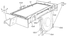
- FIG. 1 is a perspective view of a display panel, a fan, and a holder unit according to one embodiment of the present invention
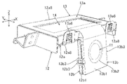
- FIG. 1 is a perspective view of a display panel, a fan, a holder unit and a cover unit according to one embodiment of the invention
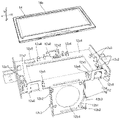
- FIG. 1 is a perspective view of a display panel and a holder unit according to an embodiment of the invention
- FIG. 1 is a perspective view of a display panel and a cover unit according to an embodiment of the invention
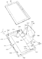
- FIG. 1 is a perspective view of a display panel and a cover unit according to an embodiment of the invention
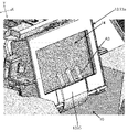
- FIG. 1 is a perspective view of part of a display unit according to an embodiment of the present invention
- FIG. 1 is a block diagram of a head-up display device according to an embodiment of the invention
- FIG. 1 is a perspective view of part of a display unit according to an embodiment of the present invention
- FIG. 1 is a cross-sectional view of a display section according to an embodiment of the present invention
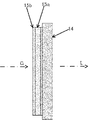
- FIG. 1 is a cross-sectional view of a display panel, a heat storage layer, and a polarizing plate according to one embodiment of the invention
- head-up display device 100 is installed in a dashboard of vehicle 200 .
- the head-up display device 100 emits display light L representing an image toward a windshield 201, which is an example of a projected member of the vehicle 200.
- the display light L is reflected by the windshield 201 and reaches the viewer 1 (for example, the driver of the vehicle 200).
- the virtual image V is displayed so that it can be visually recognized by the viewer 1 .
- the head-up display device 100 includes, as shown in FIG. 2, a display unit 10, a reflecting mirror 20, a concave mirror 30, a housing 60, a control board 70, and connection lines 91 and 92 as shown in FIG. , 93 and .
- the display unit 10 emits display light L representing an image under the control of the control board 70 .
- a specific configuration of the display unit 10 will be described later.
- the reflecting mirror 20 reflects the display light L emitted by the display unit 10 toward the concave mirror 30 .
- the concave mirror 30 magnifies and reflects the display light L reflected by the reflecting mirror 20 toward the windshield 201 (see FIG. 1).
- the housing 60 is made of non-translucent resin or metal and has a substantially hollow rectangular parallelepiped shape. Each component of the head-up display device 100 is housed in the housing 60 .
- the housing 60 includes a box-shaped lower case 60b that opens upward, an upper case 60a that closes the opening of the lower case 60b, a middle case 60c that is positioned inside the lower case 60b, and a display. and a cover 60 d that covers the part 10 .
- An opening 61 is formed at a position facing the windshield 201 in the upper case 60a.
- the upper case 60 a has a curved plate-like window 50 that closes the opening 61 .
- the window part 50 is made of translucent resin such as acrylic through which the display light L is transmitted.
- the lower case 60b has a box shape that opens upward.
- the display unit 10, the middle case 60c, the reflecting mirror 20, and the concave mirror 30 are accommodated in the lower case 60b.
- the middle case 60c is positioned within the lower case 60b so as to cover the display unit 10, and forms an optical path space Sp through which the display light L travels between the reflecting mirror 20 and the concave mirror 30.
- the display unit 10 emits display light L.
- the display unit 10 includes a backlight unit 10A that emits illumination light G, and a display unit 10B that emits display light L based on the illumination light G from the backlight unit 10A.
- the display unit 10 ⁇ /b>B includes a display panel 14 , a fan 11 that is an example of a blower, a holder unit 12 , and a cover unit 13 .
- the backlight unit 10A includes a lens holder 17, a plurality of light sources 18a, a light source substrate 18b, a lens group 19, a heat sink 16, and, as shown in FIG. 11, a heat storage layer 15a and a polarizing plate 15b. .
- the heat sink 16 is exposed to the outside of the head-up display device 100 (see FIG. 2) and absorbs and dissipates heat generated by the light source substrate 18b.
- a light source substrate 18 b is installed on the heat sink 16 .
- Each light source 18a is an LED (Light Emitting Diode) element that emits illumination light G, and is mounted on the surface of the light source substrate 18b (the surface opposite to the heat sink 16).
- the lens group 19 adjusts the light emitted from each light source 18a.
- the lens group 19 consists of a condenser lens, a field lens, and the like.
- the lens holder 17 has a cylindrical shape surrounding the light source substrate 18b and the lens group 19, and guides the illumination light G emitted from each light source 18a and passed through the lens group 19 to the display panel 14.
- FIG. A lens holder 17 holds a lens group 19 .
- An end portion 17a of the lens holder 17 near the display panel 14 is inclined in a direction non-perpendicular to the traveling direction of the illumination light G. As shown in FIG. End 17a slopes away from light source 18a as fan 11 is approached.
- a display panel installation portion 12 a of the holder unit 12 which will be described later, is fitted into the end portion 17 a of the lens holder 17 .
- the display panel 14 is a TFT (Thin Film Transistor) type liquid crystal display panel controlled by the control substrate 70 .
- the display panel 14 emits display light L upon receiving the illumination light G that has passed through the lens group 19 .
- the display panel 14 has a rectangular plate shape.
- the display panel 14 is held in a tilted posture with respect to the lens group 19 .
- the display panel 14 has a frame-shaped metal bezel 14 a surrounding the outer periphery of the display panel 14 .
- the heat storage layer 15a is adhered to the incident surface of the display panel 14 for the illumination light G with an optical adhesive.
- the heat storage layer 15 a is made of a material such as glass having a larger heat capacity than the display panel 14 .
- the heat storage layer 15 a has a function of suppressing or delaying the temperature rise of the display panel 14 by storing heat from the display panel 14 .
- the polarizing plate 15b is laminated on the surface of the heat storage layer 15a opposite to the display panel 14 side.
- the polarizing plate 15b is, for example, CMF (Cold Mirror Film), which is a type of optical film formed of a dielectric multilayer film.
- CMF has the property of transmitting only visible light polarized in a specific direction and reflecting polarized light in a direction different from this specific direction, infrared rays or ultraviolet rays.
- the polarizing plate 15b suppresses temperature rise of the display panel 14 by reflecting heat rays such as infrared rays contained in the illumination light G. As shown in FIG.
- the holder unit 12 includes a display panel installation portion 12a on which the display panel 14 is installed, and a fan installation portion 12b on which the fan 11 is installed.
- the display panel installation portion 12a and the fan installation portion 12b are integrally formed of resin, for example.
- the longitudinal direction of the display panel 14 is defined as the X direction
- the lateral direction of the display panel 14 is defined as the Y direction
- the thickness direction of the display panel 14 is defined as the Z direction.
- the display panel installation portion 12a includes a frame portion 12a1, an elastic support portion 12a2, pressing portions 12a3 and 12a4, stoppers 12a5, 12a6 and 12a7, and a locking portion 12a8.
- the frame portion 12 a 1 has a rectangular frame plate shape along the outer circumference of the display panel 14 .
- a display panel 14 is installed on the frame portion 12a1.
- An elastic support portion 12a2, pressing portions 12a3 and 12a4, and stoppers 12a5, 12a6 and 12a7 are provided on the surface of the frame portion 12a1 on which the display panel 14 is installed.
- a plurality of stoppers 12 a 5 two in this example, position the display panel 14 in the Z direction while the elastic support portions 12 a 2 are elastically deformed by the display panel 14 .
- the pressing portions 12 a 3 and 12 a 4 and the stoppers 12 a 6 and 12 a 7 are arranged so as to surround the outer circumference of the display panel 14 .
- a plurality of pressing portions 12a3, two in this example, are arranged so as to sandwich the display panel 14 from the X direction between two stoppers 12a7.
- the two pressing portions 12a3 elastically press the display panel 14 in the X direction toward the two stoppers 12a7.
- a plurality of pressing portions 12a4, two in this example, are arranged so as to sandwich the display panel 14 from the Y direction between two stoppers 12a6.
- the two pressing portions 12a4 elastically press the display panel 14 in the Y direction toward the two stoppers 12a6.
- Each locking portion 12a8 is locked to a convex portion 13a6 (see FIG. 4) of the cover unit 13, which will be described later.
- Each engaging portion 12a8 is a U-shaped hook extending in a direction orthogonal to the frame portion 12a1 on the outer periphery of the frame portion 12a1.
- Two of the three locking portions 12a8 are located at both ends of the frame portion 12a1 in the X direction.
- the remaining one locking portion 12a8 is located on the opposite side in the Y direction from the two locking portions 12a8, and is located in the center of the frame portion 12a1 in the X direction.
- the fan installation portion 12b is connected to the display panel installation portion 12a at an obtuse angle. As shown in FIG. 5, the fan installation portion 12b is provided at the center in the X direction of the outer peripheral edge of the frame portion 12a1.
- the fan installation portion 12b includes a base plate portion 12b1, a plurality of support pin portions 12b2, and a plurality of protrusions 12b3.
- the base plate portion 12b1 has a rectangular plate shape.
- a through hole 12b4 is formed in the central portion of the base plate portion 12b1.
- the upper side portion of the base plate portion 12b1 is connected to the outer peripheral portion of the frame portion 12a1.
- the convex portion 12b3 is a portion to be locked by the locking portion 13b3 (see FIG. 4) of the fan cover portion 13b.
- a plurality of protrusions 12b3, two in this example, are formed on the side surface of the base plate portion 12b1 and are arranged so as to sandwich the base plate portion 12b1 in the X direction.
- the two support pin portions 12b2 are portions that support the fan 11 (see FIG. 3), and are formed in a convex shape on the surface of the base plate portion 12b1 on which the fan 11 is installed.
- the two support pin portions 12b2 are positioned on a diagonal line of the rectangular plate-shaped base plate portion 12b1.
- the cover unit 13 is attached to the holder unit 12 so as to sandwich the display panel 14 and the fan 11 between itself and the holder unit 12 .
- the cover unit 13 includes a display panel cover portion 13a that covers the display panel 14 installed in the display panel installation portion 12a, and a fan cover portion 13b that covers the fan 11 installed in the fan installation portion 12b.
- the display panel cover portion 13a and the fan cover portion 13b are integrally formed of resin, for example.
- the display panel cover portion 13a includes a frame portion 13a1, positioning portions 13a2, 13a3, and 13a4, an air passing portion 13a5, a plurality of protrusions 13a6, and side walls 13a7.
- the frame portion 13 a 1 has a rectangular frame plate shape along the outer circumference of the display panel 14 .
- the side wall 13a7 is erected on the outer peripheral edge of the frame portion 13a1.
- a plurality of protrusions 13a6, three in this example, are provided on the outer surface of the side wall 13a7.
- Each locking portion 12a8 (see FIG. 4) of the display panel installation portion 12a is fitted to each convex portion 13a6.
- a plurality of positioning portions 13a2, 13a3, and 13a4 are provided on the surface of the frame portion 13a1 on which the display panel 14 is installed.
- the air passage portion 13a5 is located at a connecting portion of the display panel cover portion 13a and the fan cover portion 13b.
- the air passage portion 13a5 has a cavity for collecting the wind from the fan 11 on the surface (light emission surface) of the display panel 14 at the center in the X direction.
- the air passage portion 13a5 has a curved plate shape when viewed in the X direction, and is formed with a step with respect to the frame portion 13a1 so as to move away from the display panel .
- the air passage portion 13a5 is located in the center portion of the frame portion 13a1 in the X direction.
- the fan cover portion 13b includes a base plate portion 13b1 and a plurality of locking portions 13b3.
- the base plate portion 13b1 has a rectangular plate shape.
- the base plate portion 13b1 sandwiches the fan 11 with the base plate portion 12b1 of the fan installation portion 12b.
- a through hole 13b2 is formed in the central portion of the base plate portion 13b1.
- the through hole 13b2 is formed for the fan 11 to draw air.
- the locking portion 13b3 is locked to the convex portion 12b3 of the fan mounting portion 12b.
- a plurality of locking portions 13b3, two in this example, are formed on the side surface of the base plate portion 13b1 and arranged so as to sandwich the base plate portion 13b1 in the X direction.
- the locking portion 13b3 is, for example, a U-shaped hook.
- the fan 11 is a blower type fan and has a rectangular plate shape.
- the fan 11 is held between the fan mounting portion 12b and the fan cover portion 13b.
- the fan 11 includes an intake portion 11i for sucking air and an exhaust portion 11o for exhausting air.
- the intake portion 11 i is located on the main surface side of the fan 11 and faces the control board 70 .
- the exhaust portion 11o is positioned on the side surface of the fan 11 and is positioned to face the air passing portion 13a5.
- the fan 11 is provided along the height direction of the vehicle 200 (see FIG. 1). In this example, the fan 11 is located on the opposite side of the display section 10 to the optical path space Sp.
- An intake portion 11 i of the fan 11 is provided so as to face the control board 70 .
- the control board 70 consists of a printed circuit board on which various electronic components such as a CPU (Central Processing Unit) are mounted, and controls the fan 11 of the display section 10, the display panel 14 and the light source 18a.
- the control board 70 is fixed to the lower case 60b so as to face the intake portion 11i of the fan 11 and is covered with the cover 60d.
- Control board 70 is provided along the height direction of vehicle 200 (see FIG. 1).
- connection lines 91, 92, and 93 electrically connect the control board 70, the light source board 18b, the fan 11, and the display panel .
- the connection line 91 connects between the control board 70 and the light source board 18b.
- a connection line 92 connects between the light source board 18 b and the fan 11 .
- a connection line 93 connects between the control board 70 and the display panel 14 .
- Each connection line 91, 92, 93 is, for example, a flexible flat cable.
- the control board 70 outputs a control signal for controlling the light source 18a to the light source board 18b via the connection line 91.
- the control board 70 also outputs a control signal for controlling the fan 11 to the fan 11 via the connection line 91 , the light source board 18 b and the connection line 92 . That is, when the control board 70 controls the fan 11, the light source board 18b is used as a relay board for relaying control signals.
- the control board 70 outputs a control signal for controlling the display panel 14 to the display panel 14 via the connection line 93 .
- the air discharged from the exhaust portion 11o of the fan 11 is supplied along the Y direction to the light exit surface of the display panel 14 at the center in the X direction, as indicated by an arrow A3 in FIG. be. This makes it possible to intensively cool the central portion of the display panel 14, which is likely to be heated by sunlight.
- the display panel 14 is installed in the display panel installation portion 12 a of the holder unit 12 and the fan 11 is installed in the fan installation portion 12 b of the holder unit 12 .
- the cover unit 13 is attached to the holder unit 12 .
- each engaging portion 12a8 is fitted into the corresponding convex portion 13a6, and each engaging portion 13b3 is fitted into the corresponding convex portion 12b3. This completes the assembly of the display unit 10B.
- this display unit 10B is attached to the backlight unit 10A.
- the display panel installation portion 12a is attached to the end portion 17a of the lens holder 17 of the backlight unit 10A.
- the light source board 18b and the fan 11 are connected via a connection line 92
- the control board 70 and the light source board 18b are connected via a connection line 91
- the control board 70 is connected via a connection line 93. Connections between panels 14 are provided. Thus, the assembly of the display unit 10 is completed.
- the head-up display device 100 includes a light source 18a that emits light, a display panel 14 that receives illumination light G from the light source 18a and emits display light L, and a blower that blows air toward the display panel 14.
- a fan 11 as an example, a light source board 18b on which the light source 18a is provided, a control board 70 that controls the light source 18a and the fan 11, and a first connection line that electrically connects the control board 70 and the light source board 18b.
- a connection line 91 which is an example
- a connection line 92 which is an example of a second connection line that electrically connects between the fan 11 and the light source substrate 18b.
- the light source board 18b has a function as a relay board that relays between the fan 11 and the control board 70 in addition to functioning as a board on which the light source 18a is mounted. Therefore, there is no need to separately prepare a relay board, and the trouble of connecting the relay board to the fan 11, the control board 70, or the like can be reduced. Thereby, the head-up display device 100 can be assembled more easily. Moreover, since the relay board is not required, the degree of freedom in layout of the head-up display device 100, particularly the light source board 18b, the fan 11, the control board 70 and the display panel 14 increases.
- the head-up display device 100 includes a holder unit 12 having a display panel installation portion 12a where the display panel 14 is installed and a fan installation portion 12b which is an example of a ventilation installation portion where the fan 11 is installed, and a display panel.
- a cover unit 13 having a display panel cover portion 13a that sandwiches the display panel 14 between itself and the installation portion 12a, and a fan cover portion 13b that is an example of a ventilation cover portion that sandwiches the fan 11 between itself and the fan installation portion 12b.
- the fan 11 includes an intake portion 11i for sucking air and an exhaust portion 11o for discharging air.
- the control board 70 is provided at a position facing the intake portion 11 i of the fan 11 . According to this configuration, the temperature rise of the control board 70 can be suppressed.
- the processing section such as the CPU of the control board 70 that tends to reach high temperatures may be opposed to the intake section 11 i of the fan 11 .
- the fan 11 which is an example of the air blower, was a blower type fan, but it may be a fan other than the blower type. Also, the blower is not limited to the fan 11, and may be, for example, a compressor.
- the holder unit 12 and the cover unit 13 are made of resin in the above embodiment, at least one of the holder unit 12 and the cover unit 13 may be made of a magnetic shielding material such as metal. may This configuration is suitable for a display panel in which the bezel 14a is omitted.
- the fan 11 blows air to the light exit surface of the display panel 14, but the present invention is not limited to this, and air may be blown to the light entrance surface of the display panel 14. You may send wind to both a light-projection surface and a light-incidence surface.
- the fan 11 blows air to the central portion of the display panel 14 in the X direction. In addition, in the above embodiment, the fan 11 blows air to the display panel 14 along the Y direction.
- control board 70 was provided so as to face the intake portion 11i of the fan 11, but the installation position and installation direction of the control board 70 can be changed as appropriate.
- At least one of the heat storage layer 15a and the polarizing plate 15b in the above embodiment may be omitted.
- the display unit 10 has a TFT liquid crystal display panel, but may have an organic EL (Electro-Luminescence) display panel instead.
- the light source 18a is not limited to an LED, and may be a laser or the like.
- at least one of the reflecting mirror 20 and the concave mirror 30 may be omitted.
- the head-up display device 100 is mounted on the vehicle 200 in the above embodiment, it may be mounted on a vehicle other than the vehicle 200, such as an airplane or a ship. Further, the projected member is not limited to the windshield, and may be a dedicated combiner. Also, the window portion 50 may be omitted.
Landscapes
- Engineering & Computer Science (AREA)
- Mechanical Engineering (AREA)
- Chemical & Material Sciences (AREA)
- Combustion & Propulsion (AREA)
- Transportation (AREA)
- Physics & Mathematics (AREA)
- General Physics & Mathematics (AREA)
- Optics & Photonics (AREA)
- Instrument Panels (AREA)
- Devices For Indicating Variable Information By Combining Individual Elements (AREA)
Priority Applications (3)
| Application Number | Priority Date | Filing Date | Title |
|---|---|---|---|
| JP2023523476A JPWO2022250033A1 (https=) | 2021-05-25 | 2022-05-24 | |
| CN202290000446.2U CN220923816U (zh) | 2021-05-25 | 2022-05-24 | 平视显示装置 |
| DE112022002782.7T DE112022002782T5 (de) | 2021-05-25 | 2022-05-24 | Head-up-Display-Vorrichtung |
Applications Claiming Priority (2)
| Application Number | Priority Date | Filing Date | Title |
|---|---|---|---|
| JP2021087613 | 2021-05-25 | ||
| JP2021-087613 | 2021-05-25 |
Publications (1)
| Publication Number | Publication Date |
|---|---|
| WO2022250033A1 true WO2022250033A1 (ja) | 2022-12-01 |
Family
ID=84228840
Family Applications (1)
| Application Number | Title | Priority Date | Filing Date |
|---|---|---|---|
| PCT/JP2022/021190 Ceased WO2022250033A1 (ja) | 2021-05-25 | 2022-05-24 | ヘッドアップディスプレイ装置 |
Country Status (4)
| Country | Link |
|---|---|
| JP (1) | JPWO2022250033A1 (https=) |
| CN (1) | CN220923816U (https=) |
| DE (1) | DE112022002782T5 (https=) |
| WO (1) | WO2022250033A1 (https=) |
Cited By (2)
| Publication number | Priority date | Publication date | Assignee | Title |
|---|---|---|---|---|
| WO2024147333A1 (ja) * | 2023-01-05 | 2024-07-11 | 日本精機株式会社 | ヘッドアップディスプレイ装置 |
| JP2024163737A (ja) * | 2023-05-12 | 2024-11-22 | 矢崎総業株式会社 | 表示器、及び、車両用表示装置 |
Citations (3)
| Publication number | Priority date | Publication date | Assignee | Title |
|---|---|---|---|---|
| JPS63189827U (https=) * | 1987-05-29 | 1988-12-06 | ||
| JP2009288484A (ja) * | 2008-05-29 | 2009-12-10 | Nippon Seiki Co Ltd | 発光表示装置 |
| WO2016121269A1 (ja) * | 2015-01-27 | 2016-08-04 | 日本精機株式会社 | 車両用ヘッドアップディスプレイ装置 |
Family Cites Families (1)
| Publication number | Priority date | Publication date | Assignee | Title |
|---|---|---|---|---|
| DE112019005338T5 (de) | 2018-10-25 | 2021-07-08 | Nippon Seiki Co., Ltd. | Head-up-Display-Vorrichtung |
-
2022
- 2022-05-24 JP JP2023523476A patent/JPWO2022250033A1/ja active Pending
- 2022-05-24 DE DE112022002782.7T patent/DE112022002782T5/de active Pending
- 2022-05-24 WO PCT/JP2022/021190 patent/WO2022250033A1/ja not_active Ceased
- 2022-05-24 CN CN202290000446.2U patent/CN220923816U/zh active Active
Patent Citations (3)
| Publication number | Priority date | Publication date | Assignee | Title |
|---|---|---|---|---|
| JPS63189827U (https=) * | 1987-05-29 | 1988-12-06 | ||
| JP2009288484A (ja) * | 2008-05-29 | 2009-12-10 | Nippon Seiki Co Ltd | 発光表示装置 |
| WO2016121269A1 (ja) * | 2015-01-27 | 2016-08-04 | 日本精機株式会社 | 車両用ヘッドアップディスプレイ装置 |
Cited By (3)
| Publication number | Priority date | Publication date | Assignee | Title |
|---|---|---|---|---|
| WO2024147333A1 (ja) * | 2023-01-05 | 2024-07-11 | 日本精機株式会社 | ヘッドアップディスプレイ装置 |
| JP2024163737A (ja) * | 2023-05-12 | 2024-11-22 | 矢崎総業株式会社 | 表示器、及び、車両用表示装置 |
| JP7704803B2 (ja) | 2023-05-12 | 2025-07-08 | 矢崎総業株式会社 | 表示器、及び、車両用表示装置 |
Also Published As
| Publication number | Publication date |
|---|---|
| CN220923816U (zh) | 2024-05-10 |
| JPWO2022250033A1 (https=) | 2022-12-01 |
| DE112022002782T5 (de) | 2024-03-07 |
Similar Documents
| Publication | Publication Date | Title |
|---|---|---|
| JP6216307B2 (ja) | ヘッドアップディスプレイ装置及びバックライト装置 | |
| CN105074323B (zh) | 背光装置以及显示装置 | |
| JP5032650B2 (ja) | テレビおよび電子機器 | |
| US10036848B2 (en) | Lighting device, display device, and television device | |
| CN104185811A (zh) | 显示装置和电视接收装置 | |
| WO2022250033A1 (ja) | ヘッドアップディスプレイ装置 | |
| JP2003330377A (ja) | 電気光学装置および両面テープ、並びに電子機器 | |
| JP6303447B2 (ja) | 電気光学モジュールおよび投射型表示装置 | |
| JP4725116B2 (ja) | 表示モジュール | |
| CN218197927U (zh) | 平视显示装置 | |
| JPWO2019181927A1 (ja) | ヘッドアップディスプレイ | |
| JP7145699B2 (ja) | ヘッドアップディスプレイ装置 | |
| US20120281148A1 (en) | Lighting device, display device and television receiver | |
| JP2018028503A (ja) | 表示装置 | |
| CN112912946B (zh) | 平视显示装置 | |
| JP7474028B2 (ja) | ヘッドアップディスプレイ | |
| JP7143153B2 (ja) | 表示器、及び、表示器を備えるヘッドアップディスプレイ装置 | |
| WO2025220358A1 (ja) | 画像表示装置 | |
| US20250389956A1 (en) | Image display device | |
| US20250389957A1 (en) | Image display device | |
| JP7704803B2 (ja) | 表示器、及び、車両用表示装置 | |
| WO2025220359A1 (ja) | 画像表示装置 | |
| JP2020071941A (ja) | 照明装置および表示装置 | |
| JP2025009823A (ja) | ヘッドアップディスプレイ装置 | |
| JP2024089838A (ja) | バックライト装置 |
Legal Events
| Date | Code | Title | Description |
|---|---|---|---|
| 121 | Ep: the epo has been informed by wipo that ep was designated in this application |
Ref document number: 22811303 Country of ref document: EP Kind code of ref document: A1 |
|
| WWE | Wipo information: entry into national phase |
Ref document number: 2023523476 Country of ref document: JP |
|
| WWE | Wipo information: entry into national phase |
Ref document number: 202290000446.2 Country of ref document: CN |
|
| WWE | Wipo information: entry into national phase |
Ref document number: 112022002782 Country of ref document: DE |
|
| 122 | Ep: pct application non-entry in european phase |
Ref document number: 22811303 Country of ref document: EP Kind code of ref document: A1 |