WO2022250033A1 - ヘッドアップディスプレイ装置 - Google Patents
ヘッドアップディスプレイ装置 Download PDFInfo
- Publication number
- WO2022250033A1 WO2022250033A1 PCT/JP2022/021190 JP2022021190W WO2022250033A1 WO 2022250033 A1 WO2022250033 A1 WO 2022250033A1 JP 2022021190 W JP2022021190 W JP 2022021190W WO 2022250033 A1 WO2022250033 A1 WO 2022250033A1
- Authority
- WO
- WIPO (PCT)
- Prior art keywords
- display panel
- light source
- fan
- unit
- display
- Prior art date
Links
- 238000009434 installation Methods 0.000 claims description 30
- 239000000758 substrate Substances 0.000 claims description 12
- 238000007599 discharging Methods 0.000 claims description 2
- 238000007664 blowing Methods 0.000 claims 1
- 238000005286 illumination Methods 0.000 abstract description 11
- 238000005338 heat storage Methods 0.000 description 8
- 239000011347 resin Substances 0.000 description 5
- 229920005989 resin Polymers 0.000 description 5
- 230000003287 optical effect Effects 0.000 description 4
- 238000010586 diagram Methods 0.000 description 3
- 239000002184 metal Substances 0.000 description 3
- 238000012986 modification Methods 0.000 description 3
- 230000004048 modification Effects 0.000 description 3
- 230000002093 peripheral effect Effects 0.000 description 3
- 230000000694 effects Effects 0.000 description 2
- 238000005401 electroluminescence Methods 0.000 description 2
- 239000010408 film Substances 0.000 description 2
- 239000004973 liquid crystal related substance Substances 0.000 description 2
- 239000000463 material Substances 0.000 description 2
- 238000009423 ventilation Methods 0.000 description 2
- NIXOWILDQLNWCW-UHFFFAOYSA-N acrylic acid group Chemical group C(C=C)(=O)O NIXOWILDQLNWCW-UHFFFAOYSA-N 0.000 description 1
- 239000000853 adhesive Substances 0.000 description 1
- 230000001070 adhesive effect Effects 0.000 description 1
- 238000012217 deletion Methods 0.000 description 1
- 230000037430 deletion Effects 0.000 description 1
- 239000011521 glass Substances 0.000 description 1
- 238000000034 method Methods 0.000 description 1
- 239000012788 optical film Substances 0.000 description 1
- 239000010409 thin film Substances 0.000 description 1
Images


Classifications
-
- B—PERFORMING OPERATIONS; TRANSPORTING
- B60—VEHICLES IN GENERAL
- B60K—ARRANGEMENT OR MOUNTING OF PROPULSION UNITS OR OF TRANSMISSIONS IN VEHICLES; ARRANGEMENT OR MOUNTING OF PLURAL DIVERSE PRIME-MOVERS IN VEHICLES; AUXILIARY DRIVES FOR VEHICLES; INSTRUMENTATION OR DASHBOARDS FOR VEHICLES; ARRANGEMENTS IN CONNECTION WITH COOLING, AIR INTAKE, GAS EXHAUST OR FUEL SUPPLY OF PROPULSION UNITS IN VEHICLES
- B60K35/00—Instruments specially adapted for vehicles; Arrangement of instruments in or on vehicles
- B60K35/20—Output arrangements, i.e. from vehicle to user, associated with vehicle functions or specially adapted therefor
- B60K35/21—Output arrangements, i.e. from vehicle to user, associated with vehicle functions or specially adapted therefor using visual output, e.g. blinking lights or matrix displays
- B60K35/23—Head-up displays [HUD]
-
- B—PERFORMING OPERATIONS; TRANSPORTING
- B60—VEHICLES IN GENERAL
- B60R—VEHICLES, VEHICLE FITTINGS, OR VEHICLE PARTS, NOT OTHERWISE PROVIDED FOR
- B60R16/00—Electric or fluid circuits specially adapted for vehicles and not otherwise provided for; Arrangement of elements of electric or fluid circuits specially adapted for vehicles and not otherwise provided for
- B60R16/02—Electric or fluid circuits specially adapted for vehicles and not otherwise provided for; Arrangement of elements of electric or fluid circuits specially adapted for vehicles and not otherwise provided for electric constitutive elements
-
- G—PHYSICS
- G02—OPTICS
- G02B—OPTICAL ELEMENTS, SYSTEMS OR APPARATUS
- G02B27/00—Optical systems or apparatus not provided for by any of the groups G02B1/00 - G02B26/00, G02B30/00
- G02B27/01—Head-up displays
-
- B—PERFORMING OPERATIONS; TRANSPORTING
- B60—VEHICLES IN GENERAL
- B60K—ARRANGEMENT OR MOUNTING OF PROPULSION UNITS OR OF TRANSMISSIONS IN VEHICLES; ARRANGEMENT OR MOUNTING OF PLURAL DIVERSE PRIME-MOVERS IN VEHICLES; AUXILIARY DRIVES FOR VEHICLES; INSTRUMENTATION OR DASHBOARDS FOR VEHICLES; ARRANGEMENTS IN CONNECTION WITH COOLING, AIR INTAKE, GAS EXHAUST OR FUEL SUPPLY OF PROPULSION UNITS IN VEHICLES
- B60K2360/00—Indexing scheme associated with groups B60K35/00 or B60K37/00 relating to details of instruments or dashboards
- B60K2360/92—Manufacturing of instruments
- B60K2360/96—Manufacturing of instruments by assembling
Definitions
- the present invention relates to a head-up display device.
- the head-up display device described in Patent Document 1 includes a display panel that emits display light, a lighting device that illuminates the display panel, a blower that blows air toward the display panel, and the display panel and the blower.
- a control board for controlling, and a relay board connected between the control board, the display panel, and the air blower are provided.
- Patent Document 1 In the configuration of Patent Document 1, it was necessary to connect the display panel and the air blower to the control board via the relay board, making assembly difficult.
- the present invention has been made in view of the above-mentioned actual situation, and an object of the present invention is to provide a head-up display device that can be assembled more easily.
- a head-up display device includes: a light source emitting light; a display panel that receives light from the light source and emits display light; a blower that blows air toward the display panel; a light source substrate provided with the light source; a control board that controls the light source and the air blower; a first connection line electrically connecting between the control board and the light source board; and a second connection line electrically connecting between the air blower and the light source substrate.
- the head-up display device can be assembled more easily.
- FIG. 1 is a schematic diagram of a vehicle equipped with a head-up display device according to an embodiment of the present invention
- FIG. 1 is a schematic diagram of a head-up display device according to one embodiment of the present invention
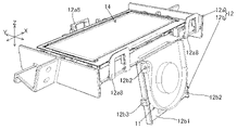
- FIG. 1 is a perspective view of a display panel, a fan, and a holder unit according to one embodiment of the present invention
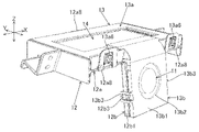
- FIG. 1 is a perspective view of a display panel, a fan, a holder unit and a cover unit according to one embodiment of the invention
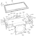
- FIG. 1 is a perspective view of a display panel and a holder unit according to an embodiment of the invention
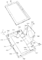
- FIG. 1 is a perspective view of a display panel and a cover unit according to an embodiment of the invention
- FIG. 1 is a perspective view of a display panel and a cover unit according to an embodiment of the invention
- FIG. 1 is a perspective view of part of a display unit according to an embodiment of the present invention
- FIG. 1 is a block diagram of a head-up display device according to an embodiment of the invention
- FIG. 1 is a perspective view of part of a display unit according to an embodiment of the present invention
- FIG. 1 is a cross-sectional view of a display section according to an embodiment of the present invention
- FIG. 1 is a cross-sectional view of a display panel, a heat storage layer, and a polarizing plate according to one embodiment of the invention
- head-up display device 100 is installed in a dashboard of vehicle 200 .
- the head-up display device 100 emits display light L representing an image toward a windshield 201, which is an example of a projected member of the vehicle 200.
- the display light L is reflected by the windshield 201 and reaches the viewer 1 (for example, the driver of the vehicle 200).
- the virtual image V is displayed so that it can be visually recognized by the viewer 1 .
- the head-up display device 100 includes, as shown in FIG. 2, a display unit 10, a reflecting mirror 20, a concave mirror 30, a housing 60, a control board 70, and connection lines 91 and 92 as shown in FIG. , 93 and .
- the display unit 10 emits display light L representing an image under the control of the control board 70 .
- a specific configuration of the display unit 10 will be described later.
- the reflecting mirror 20 reflects the display light L emitted by the display unit 10 toward the concave mirror 30 .
- the concave mirror 30 magnifies and reflects the display light L reflected by the reflecting mirror 20 toward the windshield 201 (see FIG. 1).
- the housing 60 is made of non-translucent resin or metal and has a substantially hollow rectangular parallelepiped shape. Each component of the head-up display device 100 is housed in the housing 60 .
- the housing 60 includes a box-shaped lower case 60b that opens upward, an upper case 60a that closes the opening of the lower case 60b, a middle case 60c that is positioned inside the lower case 60b, and a display. and a cover 60 d that covers the part 10 .
- An opening 61 is formed at a position facing the windshield 201 in the upper case 60a.
- the upper case 60 a has a curved plate-like window 50 that closes the opening 61 .
- the window part 50 is made of translucent resin such as acrylic through which the display light L is transmitted.
- the lower case 60b has a box shape that opens upward.
- the display unit 10, the middle case 60c, the reflecting mirror 20, and the concave mirror 30 are accommodated in the lower case 60b.
- the middle case 60c is positioned within the lower case 60b so as to cover the display unit 10, and forms an optical path space Sp through which the display light L travels between the reflecting mirror 20 and the concave mirror 30.
- the display unit 10 emits display light L.
- the display unit 10 includes a backlight unit 10A that emits illumination light G, and a display unit 10B that emits display light L based on the illumination light G from the backlight unit 10A.
- the display unit 10 ⁇ /b>B includes a display panel 14 , a fan 11 that is an example of a blower, a holder unit 12 , and a cover unit 13 .
- the backlight unit 10A includes a lens holder 17, a plurality of light sources 18a, a light source substrate 18b, a lens group 19, a heat sink 16, and, as shown in FIG. 11, a heat storage layer 15a and a polarizing plate 15b. .
- the heat sink 16 is exposed to the outside of the head-up display device 100 (see FIG. 2) and absorbs and dissipates heat generated by the light source substrate 18b.
- a light source substrate 18 b is installed on the heat sink 16 .
- Each light source 18a is an LED (Light Emitting Diode) element that emits illumination light G, and is mounted on the surface of the light source substrate 18b (the surface opposite to the heat sink 16).
- the lens group 19 adjusts the light emitted from each light source 18a.
- the lens group 19 consists of a condenser lens, a field lens, and the like.
- the lens holder 17 has a cylindrical shape surrounding the light source substrate 18b and the lens group 19, and guides the illumination light G emitted from each light source 18a and passed through the lens group 19 to the display panel 14.
- FIG. A lens holder 17 holds a lens group 19 .
- An end portion 17a of the lens holder 17 near the display panel 14 is inclined in a direction non-perpendicular to the traveling direction of the illumination light G. As shown in FIG. End 17a slopes away from light source 18a as fan 11 is approached.
- a display panel installation portion 12 a of the holder unit 12 which will be described later, is fitted into the end portion 17 a of the lens holder 17 .
- the display panel 14 is a TFT (Thin Film Transistor) type liquid crystal display panel controlled by the control substrate 70 .
- the display panel 14 emits display light L upon receiving the illumination light G that has passed through the lens group 19 .
- the display panel 14 has a rectangular plate shape.
- the display panel 14 is held in a tilted posture with respect to the lens group 19 .
- the display panel 14 has a frame-shaped metal bezel 14 a surrounding the outer periphery of the display panel 14 .
- the heat storage layer 15a is adhered to the incident surface of the display panel 14 for the illumination light G with an optical adhesive.
- the heat storage layer 15 a is made of a material such as glass having a larger heat capacity than the display panel 14 .
- the heat storage layer 15 a has a function of suppressing or delaying the temperature rise of the display panel 14 by storing heat from the display panel 14 .
- the polarizing plate 15b is laminated on the surface of the heat storage layer 15a opposite to the display panel 14 side.
- the polarizing plate 15b is, for example, CMF (Cold Mirror Film), which is a type of optical film formed of a dielectric multilayer film.
- CMF has the property of transmitting only visible light polarized in a specific direction and reflecting polarized light in a direction different from this specific direction, infrared rays or ultraviolet rays.
- the polarizing plate 15b suppresses temperature rise of the display panel 14 by reflecting heat rays such as infrared rays contained in the illumination light G. As shown in FIG.
- the holder unit 12 includes a display panel installation portion 12a on which the display panel 14 is installed, and a fan installation portion 12b on which the fan 11 is installed.
- the display panel installation portion 12a and the fan installation portion 12b are integrally formed of resin, for example.
- the longitudinal direction of the display panel 14 is defined as the X direction
- the lateral direction of the display panel 14 is defined as the Y direction
- the thickness direction of the display panel 14 is defined as the Z direction.
- the display panel installation portion 12a includes a frame portion 12a1, an elastic support portion 12a2, pressing portions 12a3 and 12a4, stoppers 12a5, 12a6 and 12a7, and a locking portion 12a8.
- the frame portion 12 a 1 has a rectangular frame plate shape along the outer circumference of the display panel 14 .
- a display panel 14 is installed on the frame portion 12a1.
- An elastic support portion 12a2, pressing portions 12a3 and 12a4, and stoppers 12a5, 12a6 and 12a7 are provided on the surface of the frame portion 12a1 on which the display panel 14 is installed.
- a plurality of stoppers 12 a 5 two in this example, position the display panel 14 in the Z direction while the elastic support portions 12 a 2 are elastically deformed by the display panel 14 .
- the pressing portions 12 a 3 and 12 a 4 and the stoppers 12 a 6 and 12 a 7 are arranged so as to surround the outer circumference of the display panel 14 .
- a plurality of pressing portions 12a3, two in this example, are arranged so as to sandwich the display panel 14 from the X direction between two stoppers 12a7.
- the two pressing portions 12a3 elastically press the display panel 14 in the X direction toward the two stoppers 12a7.
- a plurality of pressing portions 12a4, two in this example, are arranged so as to sandwich the display panel 14 from the Y direction between two stoppers 12a6.
- the two pressing portions 12a4 elastically press the display panel 14 in the Y direction toward the two stoppers 12a6.
- Each locking portion 12a8 is locked to a convex portion 13a6 (see FIG. 4) of the cover unit 13, which will be described later.
- Each engaging portion 12a8 is a U-shaped hook extending in a direction orthogonal to the frame portion 12a1 on the outer periphery of the frame portion 12a1.
- Two of the three locking portions 12a8 are located at both ends of the frame portion 12a1 in the X direction.
- the remaining one locking portion 12a8 is located on the opposite side in the Y direction from the two locking portions 12a8, and is located in the center of the frame portion 12a1 in the X direction.
- the fan installation portion 12b is connected to the display panel installation portion 12a at an obtuse angle. As shown in FIG. 5, the fan installation portion 12b is provided at the center in the X direction of the outer peripheral edge of the frame portion 12a1.
- the fan installation portion 12b includes a base plate portion 12b1, a plurality of support pin portions 12b2, and a plurality of protrusions 12b3.
- the base plate portion 12b1 has a rectangular plate shape.
- a through hole 12b4 is formed in the central portion of the base plate portion 12b1.
- the upper side portion of the base plate portion 12b1 is connected to the outer peripheral portion of the frame portion 12a1.
- the convex portion 12b3 is a portion to be locked by the locking portion 13b3 (see FIG. 4) of the fan cover portion 13b.
- a plurality of protrusions 12b3, two in this example, are formed on the side surface of the base plate portion 12b1 and are arranged so as to sandwich the base plate portion 12b1 in the X direction.
- the two support pin portions 12b2 are portions that support the fan 11 (see FIG. 3), and are formed in a convex shape on the surface of the base plate portion 12b1 on which the fan 11 is installed.
- the two support pin portions 12b2 are positioned on a diagonal line of the rectangular plate-shaped base plate portion 12b1.
- the cover unit 13 is attached to the holder unit 12 so as to sandwich the display panel 14 and the fan 11 between itself and the holder unit 12 .
- the cover unit 13 includes a display panel cover portion 13a that covers the display panel 14 installed in the display panel installation portion 12a, and a fan cover portion 13b that covers the fan 11 installed in the fan installation portion 12b.
- the display panel cover portion 13a and the fan cover portion 13b are integrally formed of resin, for example.
- the display panel cover portion 13a includes a frame portion 13a1, positioning portions 13a2, 13a3, and 13a4, an air passing portion 13a5, a plurality of protrusions 13a6, and side walls 13a7.
- the frame portion 13 a 1 has a rectangular frame plate shape along the outer circumference of the display panel 14 .
- the side wall 13a7 is erected on the outer peripheral edge of the frame portion 13a1.
- a plurality of protrusions 13a6, three in this example, are provided on the outer surface of the side wall 13a7.
- Each locking portion 12a8 (see FIG. 4) of the display panel installation portion 12a is fitted to each convex portion 13a6.
- a plurality of positioning portions 13a2, 13a3, and 13a4 are provided on the surface of the frame portion 13a1 on which the display panel 14 is installed.
- the air passage portion 13a5 is located at a connecting portion of the display panel cover portion 13a and the fan cover portion 13b.
- the air passage portion 13a5 has a cavity for collecting the wind from the fan 11 on the surface (light emission surface) of the display panel 14 at the center in the X direction.
- the air passage portion 13a5 has a curved plate shape when viewed in the X direction, and is formed with a step with respect to the frame portion 13a1 so as to move away from the display panel .
- the air passage portion 13a5 is located in the center portion of the frame portion 13a1 in the X direction.
- the fan cover portion 13b includes a base plate portion 13b1 and a plurality of locking portions 13b3.
- the base plate portion 13b1 has a rectangular plate shape.
- the base plate portion 13b1 sandwiches the fan 11 with the base plate portion 12b1 of the fan installation portion 12b.
- a through hole 13b2 is formed in the central portion of the base plate portion 13b1.
- the through hole 13b2 is formed for the fan 11 to draw air.
- the locking portion 13b3 is locked to the convex portion 12b3 of the fan mounting portion 12b.
- a plurality of locking portions 13b3, two in this example, are formed on the side surface of the base plate portion 13b1 and arranged so as to sandwich the base plate portion 13b1 in the X direction.
- the locking portion 13b3 is, for example, a U-shaped hook.
- the fan 11 is a blower type fan and has a rectangular plate shape.
- the fan 11 is held between the fan mounting portion 12b and the fan cover portion 13b.
- the fan 11 includes an intake portion 11i for sucking air and an exhaust portion 11o for exhausting air.
- the intake portion 11 i is located on the main surface side of the fan 11 and faces the control board 70 .
- the exhaust portion 11o is positioned on the side surface of the fan 11 and is positioned to face the air passing portion 13a5.
- the fan 11 is provided along the height direction of the vehicle 200 (see FIG. 1). In this example, the fan 11 is located on the opposite side of the display section 10 to the optical path space Sp.
- An intake portion 11 i of the fan 11 is provided so as to face the control board 70 .
- the control board 70 consists of a printed circuit board on which various electronic components such as a CPU (Central Processing Unit) are mounted, and controls the fan 11 of the display section 10, the display panel 14 and the light source 18a.
- the control board 70 is fixed to the lower case 60b so as to face the intake portion 11i of the fan 11 and is covered with the cover 60d.
- Control board 70 is provided along the height direction of vehicle 200 (see FIG. 1).
- connection lines 91, 92, and 93 electrically connect the control board 70, the light source board 18b, the fan 11, and the display panel .
- the connection line 91 connects between the control board 70 and the light source board 18b.
- a connection line 92 connects between the light source board 18 b and the fan 11 .
- a connection line 93 connects between the control board 70 and the display panel 14 .
- Each connection line 91, 92, 93 is, for example, a flexible flat cable.
- the control board 70 outputs a control signal for controlling the light source 18a to the light source board 18b via the connection line 91.
- the control board 70 also outputs a control signal for controlling the fan 11 to the fan 11 via the connection line 91 , the light source board 18 b and the connection line 92 . That is, when the control board 70 controls the fan 11, the light source board 18b is used as a relay board for relaying control signals.
- the control board 70 outputs a control signal for controlling the display panel 14 to the display panel 14 via the connection line 93 .
- the air discharged from the exhaust portion 11o of the fan 11 is supplied along the Y direction to the light exit surface of the display panel 14 at the center in the X direction, as indicated by an arrow A3 in FIG. be. This makes it possible to intensively cool the central portion of the display panel 14, which is likely to be heated by sunlight.
- the display panel 14 is installed in the display panel installation portion 12 a of the holder unit 12 and the fan 11 is installed in the fan installation portion 12 b of the holder unit 12 .
- the cover unit 13 is attached to the holder unit 12 .
- each engaging portion 12a8 is fitted into the corresponding convex portion 13a6, and each engaging portion 13b3 is fitted into the corresponding convex portion 12b3. This completes the assembly of the display unit 10B.
- this display unit 10B is attached to the backlight unit 10A.
- the display panel installation portion 12a is attached to the end portion 17a of the lens holder 17 of the backlight unit 10A.
- the light source board 18b and the fan 11 are connected via a connection line 92
- the control board 70 and the light source board 18b are connected via a connection line 91
- the control board 70 is connected via a connection line 93. Connections between panels 14 are provided. Thus, the assembly of the display unit 10 is completed.
- the head-up display device 100 includes a light source 18a that emits light, a display panel 14 that receives illumination light G from the light source 18a and emits display light L, and a blower that blows air toward the display panel 14.
- a fan 11 as an example, a light source board 18b on which the light source 18a is provided, a control board 70 that controls the light source 18a and the fan 11, and a first connection line that electrically connects the control board 70 and the light source board 18b.
- a connection line 91 which is an example
- a connection line 92 which is an example of a second connection line that electrically connects between the fan 11 and the light source substrate 18b.
- the light source board 18b has a function as a relay board that relays between the fan 11 and the control board 70 in addition to functioning as a board on which the light source 18a is mounted. Therefore, there is no need to separately prepare a relay board, and the trouble of connecting the relay board to the fan 11, the control board 70, or the like can be reduced. Thereby, the head-up display device 100 can be assembled more easily. Moreover, since the relay board is not required, the degree of freedom in layout of the head-up display device 100, particularly the light source board 18b, the fan 11, the control board 70 and the display panel 14 increases.
- the head-up display device 100 includes a holder unit 12 having a display panel installation portion 12a where the display panel 14 is installed and a fan installation portion 12b which is an example of a ventilation installation portion where the fan 11 is installed, and a display panel.
- a cover unit 13 having a display panel cover portion 13a that sandwiches the display panel 14 between itself and the installation portion 12a, and a fan cover portion 13b that is an example of a ventilation cover portion that sandwiches the fan 11 between itself and the fan installation portion 12b.
- the fan 11 includes an intake portion 11i for sucking air and an exhaust portion 11o for discharging air.
- the control board 70 is provided at a position facing the intake portion 11 i of the fan 11 . According to this configuration, the temperature rise of the control board 70 can be suppressed.
- the processing section such as the CPU of the control board 70 that tends to reach high temperatures may be opposed to the intake section 11 i of the fan 11 .
- the fan 11 which is an example of the air blower, was a blower type fan, but it may be a fan other than the blower type. Also, the blower is not limited to the fan 11, and may be, for example, a compressor.
- the holder unit 12 and the cover unit 13 are made of resin in the above embodiment, at least one of the holder unit 12 and the cover unit 13 may be made of a magnetic shielding material such as metal. may This configuration is suitable for a display panel in which the bezel 14a is omitted.
- the fan 11 blows air to the light exit surface of the display panel 14, but the present invention is not limited to this, and air may be blown to the light entrance surface of the display panel 14. You may send wind to both a light-projection surface and a light-incidence surface.
- the fan 11 blows air to the central portion of the display panel 14 in the X direction. In addition, in the above embodiment, the fan 11 blows air to the display panel 14 along the Y direction.
- control board 70 was provided so as to face the intake portion 11i of the fan 11, but the installation position and installation direction of the control board 70 can be changed as appropriate.
- At least one of the heat storage layer 15a and the polarizing plate 15b in the above embodiment may be omitted.
- the display unit 10 has a TFT liquid crystal display panel, but may have an organic EL (Electro-Luminescence) display panel instead.
- the light source 18a is not limited to an LED, and may be a laser or the like.
- at least one of the reflecting mirror 20 and the concave mirror 30 may be omitted.
- the head-up display device 100 is mounted on the vehicle 200 in the above embodiment, it may be mounted on a vehicle other than the vehicle 200, such as an airplane or a ship. Further, the projected member is not limited to the windshield, and may be a dedicated combiner. Also, the window portion 50 may be omitted.
Landscapes
- Engineering & Computer Science (AREA)
- Mechanical Engineering (AREA)
- Physics & Mathematics (AREA)
- General Physics & Mathematics (AREA)
- Optics & Photonics (AREA)
- Chemical & Material Sciences (AREA)
- Combustion & Propulsion (AREA)
- Transportation (AREA)
- Instrument Panels (AREA)
- Devices For Indicating Variable Information By Combining Individual Elements (AREA)
Abstract
より簡単に組み立てることができるヘッドアップディスプレイ装置を提供する。 ヘッドアップディスプレイ装置100は、光を放射する光源と、光源からの照明光を受けて表示光を出射する表示パネル14と、表示パネル14に向けて風を送るファン11と、光源が設けられる光源基板18bと、光源及びファン11を制御する制御基板70と、制御基板70及び光源基板18bの間を電気的に接続する接続線91と、ファン11及び光源基板18bの間を電気的に接続する接続線92と、を備える。
Description
本発明は、ヘッドアップディスプレイ装置に関する。
例えば、特許文献1に記載のヘッドアップディスプレイ装置は、表示光を出射する表示パネルと、表示パネルを照明する照明装置と、表示パネルに向けて風を送る送風部と、表示パネル及び送風部を制御する制御基板と、制御基板と表示パネル及び送風部の間に接続される中継基板と、を備える。
上記特許文献1の構成においては、表示パネル及び送風部を、中継基板を介して、制御基板に接続する必要があり、組み立てが困難であった。
本発明は、上記実状を鑑みてなされたものであり、より簡単に組み立てることができるヘッドアップディスプレイ装置を提供することを目的とする。
上記目的を達成するため、本発明の観点に係るヘッドアップディスプレイ装置は、
光を放射する光源と、
前記光源からの光を受けて表示光を出射する表示パネルと、
前記表示パネルに向けて風を送る送風部と、
前記光源が設けられる光源基板と、
前記光源及び前記送風部を制御する制御基板と、
前記制御基板及び前記光源基板の間を電気的に接続する第1接続線と、
前記送風部及び前記光源基板の間を電気的に接続する第2接続線と、を備える。
光を放射する光源と、
前記光源からの光を受けて表示光を出射する表示パネルと、
前記表示パネルに向けて風を送る送風部と、
前記光源が設けられる光源基板と、
前記光源及び前記送風部を制御する制御基板と、
前記制御基板及び前記光源基板の間を電気的に接続する第1接続線と、
前記送風部及び前記光源基板の間を電気的に接続する第2接続線と、を備える。
本発明によれば、ヘッドアップディスプレイ装置において、より簡単に組み立てることができる。
本発明に係るヘッドアップディスプレイ装置の一実施形態について、図面を参照して説明する。
図1に示すように、ヘッドアップディスプレイ装置100は、車両200のダッシュボード内に設置される。ヘッドアップディスプレイ装置100は、車両200の被投射部材の一例であるフロントガラス201に向けて像を表す表示光Lを出射する。表示光Lはフロントガラス201で反射して視認者1(例えば、車両200の運転者)に到達する。これにより、虚像Vが視認者1により視認可能に表示される。
図1に示すように、ヘッドアップディスプレイ装置100は、車両200のダッシュボード内に設置される。ヘッドアップディスプレイ装置100は、車両200の被投射部材の一例であるフロントガラス201に向けて像を表す表示光Lを出射する。表示光Lはフロントガラス201で反射して視認者1(例えば、車両200の運転者)に到達する。これにより、虚像Vが視認者1により視認可能に表示される。
ヘッドアップディスプレイ装置100は、図2に示すように、表示部10と、反射鏡20と、凹面鏡30と、筐体60と、制御基板70と、図7に示すように、接続線91,92,93と、を備える。
図2に示すように、表示部10は、制御基板70による制御のもと、像を表す表示光Lを出射する。表示部10の具体的な構成については後述する。
反射鏡20は、表示部10が出射した表示光Lを凹面鏡30に向けて反射させる。凹面鏡30は、反射鏡20で反射した表示光Lをフロントガラス201(図1参照)に向けて拡大させつつ反射させる。
図2に示すように、筐体60は、非透光性の樹脂又は金属で形成されるとともに、中空の略直方体をなす。筐体60内には、ヘッドアップディスプレイ装置100の各構成が収納されている。詳しくは、筐体60は、上方向に向けて開口する箱状をなす下ケース60bと、下ケース60bの開口部を塞ぐ上ケース60aと、下ケース60b内に位置する中ケース60cと、表示部10を覆うカバー60dと、を備える。
上ケース60aには、フロントガラス201に対向する位置に開口部61が形成されている。上ケース60aは、開口部61を塞ぐ湾曲板状の窓部50を備える。窓部50は、表示光Lが透過するアクリル等の透光性の樹脂からなる。
下ケース60bは、上方向に向けて開口した箱状をなす。下ケース60b内には、表示部10、中ケース60c、反射鏡20及び凹面鏡30が収容される。中ケース60cは、下ケース60b内で表示部10を覆うように位置し、反射鏡20と凹面鏡30の間で表示光Lが進む光路空間Spを形成する。
表示部10は、表示光Lを出射する。
表示部10は、図10に示すように、照明光Gを出射するバックライトユニット10Aと、バックライトユニット10Aからの照明光Gに基づき表示光Lを出射する表示ユニット10Bと、を備える。表示ユニット10Bは、表示パネル14と、送風部の一例であるファン11と、ホルダーユニット12と、カバーユニット13と、を備える。バックライトユニット10Aは、レンズホルダ17と、複数の光源18aと、光源基板18bと、レンズ群19と、ヒートシンク16と、図11に示すように、蓄熱層15aと、偏光板15bと、を備える。
表示部10は、図10に示すように、照明光Gを出射するバックライトユニット10Aと、バックライトユニット10Aからの照明光Gに基づき表示光Lを出射する表示ユニット10Bと、を備える。表示ユニット10Bは、表示パネル14と、送風部の一例であるファン11と、ホルダーユニット12と、カバーユニット13と、を備える。バックライトユニット10Aは、レンズホルダ17と、複数の光源18aと、光源基板18bと、レンズ群19と、ヒートシンク16と、図11に示すように、蓄熱層15aと、偏光板15bと、を備える。
図10に示すように、ヒートシンク16は、ヘッドアップディスプレイ装置100(図2参照)の外部に露出し、光源基板18bの発熱を吸収及び放熱する。ヒートシンク16には光源基板18bが設置される。
各光源18aは、照明光Gを出射するLED(Light Emitting Diode)素子であり、光源基板18bの表面(ヒートシンク16とは反対側の面)に実装される。
レンズ群19は、各光源18aから出射した光を調整する。レンズ群19は、コンデンサレンズ及びフィールドレンズ等からなる。
レンズホルダ17は、光源基板18b及びレンズ群19を周囲から囲む筒状をなし、各光源18aから出射されたレンズ群19を経た照明光Gを表示パネル14に導く。レンズホルダ17はレンズ群19を保持する。レンズホルダ17の表示パネル14に近い端部17aは、照明光Gの進行方向に対して非直角に交わる方向に傾斜している。端部17aは、ファン11に近づくにつれて光源18aから遠ざかるように傾斜する。レンズホルダ17の端部17aには、ホルダーユニット12の後述する表示パネル設置部12aが嵌め込まれている。
表示パネル14は、制御基板70により制御されるTFT(Thin Film Transistor)型の液晶表示パネルである。表示パネル14は、レンズ群19を経た照明光Gを受けて表示光Lを出射する。表示パネル14は、長方形の板状をなす。表示パネル14は、レンズ群19に対して傾斜した姿勢に保持される。
図6に示すように、表示パネル14は、表示パネル14の外周を囲む枠状の金属製のベゼル14aを有する。
図6に示すように、表示パネル14は、表示パネル14の外周を囲む枠状の金属製のベゼル14aを有する。
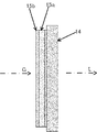
図11に示すように、蓄熱層15aは、表示パネル14の照明光Gの入射面に光学接着剤により接着されている。蓄熱層15aは、表示パネル14よりも熱容量の大きいガラス等の材質からなる。蓄熱層15aは、表示パネル14からの熱を溜めることにより、表示パネル14の温度上昇を抑制又は遅延させる機能を有する。
偏光板15bは、蓄熱層15aの表示パネル14とは反対面に積層される。偏光板15bは、例えば、誘電体多層膜で形成される光学フィルムの一種であるCMF(Cold Mirror Film)である。CMFは、特定方向の偏光の可視光のみを透過し、この特定方向とは異なる方向の偏光、赤外線又は紫外線を反射する特性を有する。偏光板15bは、照明光Gに含まれる赤外線等の熱線を反射することにより、表示パネル14の温度上昇を抑制する。
偏光板15bは、蓄熱層15aの表示パネル14とは反対面に積層される。偏光板15bは、例えば、誘電体多層膜で形成される光学フィルムの一種であるCMF(Cold Mirror Film)である。CMFは、特定方向の偏光の可視光のみを透過し、この特定方向とは異なる方向の偏光、赤外線又は紫外線を反射する特性を有する。偏光板15bは、照明光Gに含まれる赤外線等の熱線を反射することにより、表示パネル14の温度上昇を抑制する。
図3に示すように、ホルダーユニット12は、表示パネル14が設置される表示パネル設置部12aと、ファン11が設置されるファン設置部12bと、を備える。表示パネル設置部12aとファン設置部12bは、例えば、樹脂により一体形成されている。以下の説明では、表示パネル14の長手方向がX方向と規定され、表示パネル14の短手方向がY方向と規定され、表示パネル14の厚さ方向がZ方向と規定される。
図5に示すように、表示パネル設置部12aは、枠部12a1と、弾性支持部12a2と、押圧部12a3,12a4と、ストッパ12a5,12a6,12a7と、係止部12a8と、を備える。
枠部12a1は、表示パネル14の外周に沿う長方形の枠板状をなす。枠部12a1には、表示パネル14が設置される。枠部12a1における表示パネル14が設置される面には、弾性支持部12a2、押圧部12a3,12a4及びストッパ12a5,12a6,12a7が設けられる。複数、本例では3つの弾性支持部12a2は、表示パネル14をZ方向から弾性的に支持する。複数、本例では2つのストッパ12a5は、弾性支持部12a2が表示パネル14により弾性変形した状態で、表示パネル14をZ方向に位置決めする。
枠部12a1は、表示パネル14の外周に沿う長方形の枠板状をなす。枠部12a1には、表示パネル14が設置される。枠部12a1における表示パネル14が設置される面には、弾性支持部12a2、押圧部12a3,12a4及びストッパ12a5,12a6,12a7が設けられる。複数、本例では3つの弾性支持部12a2は、表示パネル14をZ方向から弾性的に支持する。複数、本例では2つのストッパ12a5は、弾性支持部12a2が表示パネル14により弾性変形した状態で、表示パネル14をZ方向に位置決めする。
押圧部12a3,12a4とストッパ12a6,12a7は、表示パネル14の外周を囲むように配置される。複数、本例では2つの押圧部12a3は、2つのストッパ12a7との間で表示パネル14をX方向から挟み込むように配置される。2つの押圧部12a3は、表示パネル14をX方向に2つのストッパ12a7に向けて弾性的に押す。
複数、本例では2つの押圧部12a4は、2つのストッパ12a6との間で表示パネル14をY方向から挟み込むように配置される。2つの押圧部12a4は、表示パネル14をY方向に2つのストッパ12a6に向けて弾性的に押す。
複数、本例では2つの押圧部12a4は、2つのストッパ12a6との間で表示パネル14をY方向から挟み込むように配置される。2つの押圧部12a4は、表示パネル14をY方向に2つのストッパ12a6に向けて弾性的に押す。
各係止部12a8は、カバーユニット13の後述する凸部13a6(図4参照)に係止する。各係止部12a8は、枠部12a1の外周に枠部12a1に直交する方向に延び、U字状のフックである。3つのうち2つの係止部12a8は、枠部12a1のX方向の両端に位置する。残りの1つの係止部12a8は、上記2つの係止部12a8とはY方向の反対側に位置し、枠部12a1のX方向の中央に位置する。
図10に示すように、ファン設置部12bは、表示パネル設置部12aに対して鈍角で連結される。図5に示すように、ファン設置部12bは、枠部12a1の外周縁部のX方向の中央部に設けられる。
図5に示すように、ファン設置部12bは、ベース板部12b1と、複数の支持ピン部12b2と、複数の凸部12b3と、を備える。ベース板部12b1は、矩形板状をなす。ベース板部12b1の中央部には貫通孔12b4が形成されている。ベース板部12b1の上辺部が枠部12a1の外周縁部に連結されている。
凸部12b3は、ファンカバー部13bの係止部13b3(図4参照)が係止する部位である。複数、本例では2つの凸部12b3は、ベース板部12b1の側面に形成され、X方向にベース板部12b1を挟み込むように配置される。
2つの支持ピン部12b2は、ファン11(図3参照)を支持する部位であり、ベース板部12b1におけるファン11が設置される面に凸状に形成される。2つの支持ピン部12b2は、矩形板状のベース板部12b1の対角線上に位置する。
凸部12b3は、ファンカバー部13bの係止部13b3(図4参照)が係止する部位である。複数、本例では2つの凸部12b3は、ベース板部12b1の側面に形成され、X方向にベース板部12b1を挟み込むように配置される。
2つの支持ピン部12b2は、ファン11(図3参照)を支持する部位であり、ベース板部12b1におけるファン11が設置される面に凸状に形成される。2つの支持ピン部12b2は、矩形板状のベース板部12b1の対角線上に位置する。
図4及び図6に示すように、カバーユニット13は、ホルダーユニット12との間で表示パネル14及びファン11を挟み込むようにホルダーユニット12に取り付けられる。カバーユニット13は、表示パネル設置部12aに設置された表示パネル14を覆う表示パネルカバー部13aと、ファン設置部12bに設置されたファン11を覆うファンカバー部13bと、を備える。表示パネルカバー部13aとファンカバー部13bは、例えば、樹脂により一体形成されている。
図6に示すように、表示パネルカバー部13aは、枠部13a1と、位置決め部13a2,13a3,13a4と、空気通過部13a5と、複数の凸部13a6と、側壁13a7と、を備える。
枠部13a1は、表示パネル14の外周に沿う長方形の枠板状をなす。
側壁13a7は、枠部13a1の外周縁部に立設される。側壁13a7の外面には、複数、本例では3つの凸部13a6が設けられる。各凸部13a6には、表示パネル設置部12aの各係止部12a8(図4参照)が嵌まる。
枠部13a1は、表示パネル14の外周に沿う長方形の枠板状をなす。
側壁13a7は、枠部13a1の外周縁部に立設される。側壁13a7の外面には、複数、本例では3つの凸部13a6が設けられる。各凸部13a6には、表示パネル設置部12aの各係止部12a8(図4参照)が嵌まる。
枠部13a1における表示パネル14が設置される面には、複数の位置決め部13a2,13a3,13a4が設けられる。
複数、本例では3つの位置決め部13a4は、表示パネル14をZ方向に位置決めするために、表示パネル14のベゼル14aに当接する凸状をなす。
複数、本例では4つの位置決め部13a2は、表示パネル14をX方向に位置決めするために、表示パネル14をX方向から挟み込む。
複数、本例では4つの位置決め部13a3は、表示パネル14をY方向に位置決めするために、表示パネル14をY方向から挟み込む。
複数、本例では3つの位置決め部13a4は、表示パネル14をZ方向に位置決めするために、表示パネル14のベゼル14aに当接する凸状をなす。
複数、本例では4つの位置決め部13a2は、表示パネル14をX方向に位置決めするために、表示パネル14をX方向から挟み込む。
複数、本例では4つの位置決め部13a3は、表示パネル14をY方向に位置決めするために、表示パネル14をY方向から挟み込む。
空気通過部13a5は、表示パネルカバー部13aにおけるファンカバー部13bとの連結部分に位置する。空気通過部13a5は、ファン11からの風を、表示パネル14の表面(光出射面)であって、X方向の中央部に集めるための空洞を有する。空気通過部13a5は、X方向から見て湾曲した板状をなし、表示パネル14から遠ざかるように枠部13a1に対して段差を持って形成される。空気通過部13a5は、X方向における枠部13a1の中央部に位置する。
図4に示すように、ファンカバー部13bは、ベース板部13b1と、複数の係止部13b3と、を備える。
ベース板部13b1は、矩形板状をなす。ベース板部13b1は、ファン設置部12bのベース板部12b1との間でファン11を挟み込む。ベース板部13b1の中央部には貫通孔13b2が形成されている。貫通孔13b2は、ファン11の吸気のために形成されている。
係止部13b3は、ファン設置部12bの凸部12b3に係止する。複数、本例では2つの係止部13b3は、ベース板部13b1の側面に形成され、X方向にベース板部13b1を挟み込むように配置される。係止部13b3は、例えば、U字状のフックである。
ベース板部13b1は、矩形板状をなす。ベース板部13b1は、ファン設置部12bのベース板部12b1との間でファン11を挟み込む。ベース板部13b1の中央部には貫通孔13b2が形成されている。貫通孔13b2は、ファン11の吸気のために形成されている。
係止部13b3は、ファン設置部12bの凸部12b3に係止する。複数、本例では2つの係止部13b3は、ベース板部13b1の側面に形成され、X方向にベース板部13b1を挟み込むように配置される。係止部13b3は、例えば、U字状のフックである。
図10に示すように、ファン11は、ブロア型のファンであり、矩形板状をなす。ファン11は、ファン設置部12bとファンカバー部13bの間に保持される。ファン11は、吸気する吸気部11iと、排気する排気部11oと、を備える。吸気部11iは、ファン11の主面側に位置し、制御基板70に対向する。排気部11oは、ファン11の側面に位置し、空気通過部13a5に対向して位置する。
図2に示すように、ファン11は、車両200(図1参照)の高さ方向に沿う向きに設けられる。本例では、ファン11は、表示部10における光路空間Spとは反対側に位置する。ファン11の吸気部11iは、制御基板70に対面するように設けられる。
図2に示すように、ファン11は、車両200(図1参照)の高さ方向に沿う向きに設けられる。本例では、ファン11は、表示部10における光路空間Spとは反対側に位置する。ファン11の吸気部11iは、制御基板70に対面するように設けられる。
制御基板70は、CPU(Central Processing Unit)等の各種電子部品が実装されたプリント回路基板からなり、表示部10のファン11、表示パネル14及び光源18aを制御する。制御基板70は、ファン11の吸気部11iに対向するように下ケース60bに固定された状態で、カバー60dにより覆われる。制御基板70は、車両200(図1参照)の高さ方向に沿う向きに設けられる。
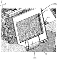
図7及び図8に示すように、接続線91,92,93は、制御基板70、光源基板18b、ファン11及び表示パネル14の間を電気的に接続する。
接続線91は、制御基板70と光源基板18bの間を接続する。接続線92は、光源基板18bとファン11の間を接続する。接続線93は、制御基板70と表示パネル14の間を接続する。各接続線91,92,93は、例えば、フレキシブルフラットケーブルである。
制御基板70は、光源18aを制御するための制御信号を接続線91を介して光源基板18bに出力する。また、制御基板70は、ファン11を制御するための制御信号を接続線91、光源基板18b及び接続線92を介してファン11に出力する。すなわち、制御基板70がファン11を制御するにあたって、光源基板18bは制御信号を中継する中継基板として利用される。制御基板70は、表示パネル14を制御するための制御信号を接続線93を介して表示パネル14に出力する。
次に、ファン11が作動した際の作用について説明する。
図10に示すように、ファン11が作動すると、矢印A1に示すように、ファン11の吸気部11iにより空気が吸入される。このとき、制御基板70のファン11に対応する側の空気がファン11により吸引される。これにより、制御基板70の温度上昇を抑制することができる。ファン11の排気部11oから供給された風は、矢印A2に示すように、空気通過部13a5に沿ってカバーユニット13とホルダーユニット12の間を進み、表示パネル14に供給される。このとき、ファン11の排気部11oから排出された空気は、図9の矢印A3に示すように、表示パネル14の光出射面であって、X方向の中央部にY方向に沿って供給される。これにより、太陽光で熱せられやすい表示パネル14の中央部を集中的に冷却することが可能となる。
図10に示すように、ファン11が作動すると、矢印A1に示すように、ファン11の吸気部11iにより空気が吸入される。このとき、制御基板70のファン11に対応する側の空気がファン11により吸引される。これにより、制御基板70の温度上昇を抑制することができる。ファン11の排気部11oから供給された風は、矢印A2に示すように、空気通過部13a5に沿ってカバーユニット13とホルダーユニット12の間を進み、表示パネル14に供給される。このとき、ファン11の排気部11oから排出された空気は、図9の矢印A3に示すように、表示パネル14の光出射面であって、X方向の中央部にY方向に沿って供給される。これにより、太陽光で熱せられやすい表示パネル14の中央部を集中的に冷却することが可能となる。
次に、表示部10、特に、表示ユニット10Bの組み立て方法について説明する。この組み立て作業は、人又はロボットにより行われる。
図3に示すように、ホルダーユニット12の表示パネル設置部12aに表示パネル14を設置し、ホルダーユニット12のファン設置部12bにファン11を設置する。そして、図4に示すように、カバーユニット13をホルダーユニット12に装着する。この際、各係止部12a8が対応する凸部13a6に、各係止部13b3が対応する凸部12b3に、それぞれ嵌め込まれる。これにより、表示ユニット10Bの組み立てが完了する。そして、図10に示すように、この表示ユニット10Bをバックライトユニット10Aに装着する。詳しくは、バックライトユニット10Aのレンズホルダ17の端部17aに表示パネル設置部12aが装着される。そして、接続線92を介して光源基板18bとファン11の間を接続し、接続線91を介して制御基板70と光源基板18bの間を接続し、接続線93を介して制御基板70と表示パネル14の間を接続する。
以上で、表示部10の組み立てが完了する。
(効果)
以上、説明した一実施形態によれば、以下の効果を奏する。
(1)ヘッドアップディスプレイ装置100は、光を放射する光源18aと、光源18aからの照明光Gを受けて表示光Lを出射する表示パネル14と、表示パネル14に向けて風を送る送風部の一例であるファン11と、光源18aが設けられる光源基板18bと、光源18a及びファン11を制御する制御基板70と、制御基板70及び光源基板18bの間を電気的に接続する第1接続線の一例である接続線91と、ファン11及び光源基板18bの間を電気的に接続する第2接続線の一例である接続線92と、を備える。
この構成によれば、光源基板18bは、光源18aが実装される基板としての機能に加えて、ファン11と制御基板70の間を中継する中継基板としての機能も有する。よって、別個に中継基板を用意する必要がなくなり、中継基板をファン11又は制御基板70等に接続する手間を減らすことができる。これにより、ヘッドアップディスプレイ装置100をより簡単に組み立てることができる。
また、中継基板が不要となるため、ヘッドアップディスプレイ装置100、特に、光源基板18b、ファン11、制御基板70及び表示パネル14のレイアウトの自由度が高まる。
(2)ヘッドアップディスプレイ装置100は、表示パネル14が設置される表示パネル設置部12a、及びファン11が設置される送風設置部の一例であるファン設置部12bを有するホルダーユニット12と、表示パネル設置部12aとの間で表示パネル14を挟み込む表示パネルカバー部13a、及びファン設置部12bとの間でファン11を挟み込む送風カバー部の一例であるファンカバー部13bを有するカバーユニット13と、を備える。
この構成によれば、ホルダーユニット12とカバーユニット13の間で表示パネル14とファン11が保持される。これにより、ファン11を保持する部材を別途用意する必要がなくなり、部品点数を減らすことができる。また、ヘッドアップディスプレイ装置100の組み立て工数を減らすことができる。
この構成によれば、ホルダーユニット12とカバーユニット13の間で表示パネル14とファン11が保持される。これにより、ファン11を保持する部材を別途用意する必要がなくなり、部品点数を減らすことができる。また、ヘッドアップディスプレイ装置100の組み立て工数を減らすことができる。
(3)ファン11は、空気を吸引する吸気部11iと、空気を吐き出す排気部11oと、を備える。制御基板70は、ファン11の吸気部11iに対面する位置に設けられる。
この構成によれば、制御基板70の温度上昇を抑制することができる。
この構成によれば、制御基板70の温度上昇を抑制することができる。
なお、本発明は以上の実施形態及び図面によって限定されるものではない。本発明の要旨を変更しない範囲で、適宜、変更(構成要素の削除も含む)を加えることが可能である。以下に、変形の一例を説明する。
(変形例)
上記実施形態において、制御基板70の高温となりやすいCPU等の処理部をファン11の吸気部11iに対向させてもよい。
上記実施形態において、制御基板70の高温となりやすいCPU等の処理部をファン11の吸気部11iに対向させてもよい。
上記実施形態においては、送風部の一例であるファン11はブロア型のファンであったが、ブロア型以外のファンであってもよい。また、送風部は、ファン11に限らず、例えば、コンプレッサであってもよい。
上記実施形態においては、ホルダーユニット12及びカバーユニット13は樹脂により形成されていたが、これに限らず、ホルダーユニット12及びカバーユニット13の少なくとも何れか一方は金属等の磁気シールド材により形成されていてもよい。この構成は、ベゼル14aが省略された表示パネルに好適である。
上記実施形態においては、ファン11は、表示パネル14の光出射面に風を送っていたが、これに限らず、表示パネル14の光入射面に風を送ってもよいし、表示パネル14の光出射面と光入射面の両方に風を送ってもよい。
上記実施形態においては、ファン11は、表示パネル14のX方向の中央部に風を送っていたが、これに限らず、表示パネル14のX方向の全域に風を送ってもよい。
また、上記実施形態においては、ファン11は、Y方向に沿って表示パネル14に風を送っていたが、これに限らず、X方向に沿って表示パネル14に風を送ってもよい。
また、上記実施形態においては、ファン11は、Y方向に沿って表示パネル14に風を送っていたが、これに限らず、X方向に沿って表示パネル14に風を送ってもよい。
上記実施形態においては、制御基板70は、ファン11の吸気部11iに対向するように設けられていたが、制御基板70の設置位置及び設置方向は適宜変更可能である。
上記実施形態における蓄熱層15aと偏光板15bの少なくとも何れか一方は省略されてもよい。
上記実施形態においては、表示部10は、TFT型の液晶表示パネルを備えていたが、これに代えて、有機EL(Electro-Luminescence)表示パネルを備えていてもよい。
また、光源18aは、LEDに限らず、レーザー等であってもよい。
さらに、反射鏡20と凹面鏡30の少なくとも何れか一方は省略されてもよい。
また、光源18aは、LEDに限らず、レーザー等であってもよい。
さらに、反射鏡20と凹面鏡30の少なくとも何れか一方は省略されてもよい。
上記実施形態においては、ヘッドアップディスプレイ装置100は車両200に搭載されていたが、車両200以外の飛行機、船等の乗り物に搭載されていてもよい。また、被投射部材はフロントガラスに限らず、専用のコンバイナであってもよい。
また、窓部50は省略されてもよい。
また、窓部50は省略されてもよい。
1 視認者
10 表示部
10A バックライトユニット
10B 表示ユニット
11 ファン
11i 吸気部
11o 排気部
12 ホルダーユニット
12a 表示パネル設置部
12b ファン設置部
12a1,13a1 枠部
12a2 弾性支持部
12b1,13b1 ベース板部
12b2 支持ピン部
12a3,12a4 押圧部
12b3,13a6 凸部
12a5,12a6,12a7 ストッパ
12b4,13b2 貫通孔
12a8,13b3 係止部
13 カバーユニット
13a 表示パネルカバー部
13b ファンカバー部
13a2,13a3,13a4 位置決め部
13a5 空気通過部
13a7 側壁
14 表示パネル
14a ベゼル
15a 蓄熱層
15b 偏光板
16 ヒートシンク
17 レンズホルダ
17a 端部
18a 光源
18b 光源基板
19 レンズ群
20 反射鏡
30 凹面鏡
50 窓部
60 筐体
60a 上ケース
60b 下ケース
60c 中ケース
60d カバー
61 開口部
70 制御基板
91,92,93 接続線
100 ヘッドアップディスプレイ装置
200 車両
201 フロントガラス
G 照明光
L 表示光
V 虚像
Sp 光路空間
Claims (3)
- 光を放射する光源と、
前記光源からの光を受けて表示光を出射する表示パネルと、
前記表示パネルに向けて風を送る送風部と、
前記光源が設けられる光源基板と、
前記光源及び前記送風部を制御する制御基板と、
前記制御基板及び前記光源基板の間を電気的に接続する第1接続線と、
前記送風部及び前記光源基板の間を電気的に接続する第2接続線と、を備える、
ヘッドアップディスプレイ装置。 - 前記表示パネルが設置される表示パネル設置部、及び前記送風部が設置される送風設置部を有するホルダーユニットと、
前記表示パネル設置部との間で前記表示パネルを挟み込む表示パネルカバー部、及び前記送風設置部との間で前記送風部を挟み込む送風カバー部を有するカバーユニットと、を備える、
請求項1に記載のヘッドアップディスプレイ装置。 - 前記送風部は、空気を吸引する吸気部と、空気を吐き出す排気部と、を備え、
前記制御基板は、前記送風部の前記吸気部に対面する位置に設けられる、
請求項1又は2に記載のヘッドアップディスプレイ装置。
Priority Applications (3)
| Application Number | Priority Date | Filing Date | Title |
|---|---|---|---|
| DE112022002782.7T DE112022002782T5 (de) | 2021-05-25 | 2022-05-24 | Head-up-Display-Vorrichtung |
| CN202290000446.2U CN220923816U (zh) | 2021-05-25 | 2022-05-24 | 平视显示装置 |
| JP2023523476A JPWO2022250033A1 (ja) | 2021-05-25 | 2022-05-24 |
Applications Claiming Priority (2)
| Application Number | Priority Date | Filing Date | Title |
|---|---|---|---|
| JP2021087613 | 2021-05-25 | ||
| JP2021-087613 | 2021-05-25 |
Publications (1)
| Publication Number | Publication Date |
|---|---|
| WO2022250033A1 true WO2022250033A1 (ja) | 2022-12-01 |
Family
ID=84228840
Family Applications (1)
| Application Number | Title | Priority Date | Filing Date |
|---|---|---|---|
| PCT/JP2022/021190 WO2022250033A1 (ja) | 2021-05-25 | 2022-05-24 | ヘッドアップディスプレイ装置 |
Country Status (4)
| Country | Link |
|---|---|
| JP (1) | JPWO2022250033A1 (ja) |
| CN (1) | CN220923816U (ja) |
| DE (1) | DE112022002782T5 (ja) |
| WO (1) | WO2022250033A1 (ja) |
Citations (3)
| Publication number | Priority date | Publication date | Assignee | Title |
|---|---|---|---|---|
| JPS63189827U (ja) * | 1987-05-29 | 1988-12-06 | ||
| JP2009288484A (ja) * | 2008-05-29 | 2009-12-10 | Nippon Seiki Co Ltd | 発光表示装置 |
| WO2016121269A1 (ja) * | 2015-01-27 | 2016-08-04 | 日本精機株式会社 | 車両用ヘッドアップディスプレイ装置 |
Family Cites Families (1)
| Publication number | Priority date | Publication date | Assignee | Title |
|---|---|---|---|---|
| DE112019005338T5 (de) | 2018-10-25 | 2021-07-08 | Nippon Seiki Co., Ltd. | Head-up-Display-Vorrichtung |
-
2022
- 2022-05-24 WO PCT/JP2022/021190 patent/WO2022250033A1/ja active Application Filing
- 2022-05-24 JP JP2023523476A patent/JPWO2022250033A1/ja active Pending
- 2022-05-24 DE DE112022002782.7T patent/DE112022002782T5/de active Pending
- 2022-05-24 CN CN202290000446.2U patent/CN220923816U/zh active Active
Patent Citations (3)
| Publication number | Priority date | Publication date | Assignee | Title |
|---|---|---|---|---|
| JPS63189827U (ja) * | 1987-05-29 | 1988-12-06 | ||
| JP2009288484A (ja) * | 2008-05-29 | 2009-12-10 | Nippon Seiki Co Ltd | 発光表示装置 |
| WO2016121269A1 (ja) * | 2015-01-27 | 2016-08-04 | 日本精機株式会社 | 車両用ヘッドアップディスプレイ装置 |
Also Published As
| Publication number | Publication date |
|---|---|
| JPWO2022250033A1 (ja) | 2022-12-01 |
| DE112022002782T5 (de) | 2024-03-07 |
| CN220923816U (zh) | 2024-05-10 |
Similar Documents
| Publication | Publication Date | Title |
|---|---|---|
| JP6216307B2 (ja) | ヘッドアップディスプレイ装置及びバックライト装置 | |
| US9195087B2 (en) | Display device and television device | |
| JP3620840B2 (ja) | 液晶表示装置 | |
| WO2014185227A1 (ja) | バックライト装置及び表示装置 | |
| US20150177453A1 (en) | Lighting device, display device, and television device | |
| EP3316029B1 (en) | Optical sheets in the backlight of a display | |
| WO2014196228A1 (ja) | 照明装置、表示装置、及びテレビ受信装置 | |
| JP2012138300A (ja) | テレビおよび電子機器 | |
| JP2003330377A (ja) | 電気光学装置および両面テープ、並びに電子機器 | |
| JP2008009010A (ja) | 表示装置 | |
| WO2015076181A1 (ja) | バックライト装置及び表示装置 | |
| JPWO2019181927A1 (ja) | ヘッドアップディスプレイ | |
| JP2018028503A (ja) | 表示装置 | |
| JP6303447B2 (ja) | 電気光学モジュールおよび投射型表示装置 | |
| US20120281148A1 (en) | Lighting device, display device and television receiver | |
| WO2016084233A1 (ja) | バックライト装置及び液晶表示装置 | |
| US9234996B2 (en) | Display device and television device having holding member | |
| WO2022250033A1 (ja) | ヘッドアップディスプレイ装置 | |
| KR20120112494A (ko) | 조명 장치 | |
| WO2020085160A1 (ja) | ヘッドアップディスプレイ装置 | |
| JP7145699B2 (ja) | ヘッドアップディスプレイ装置 | |
| WO2021246201A1 (ja) | 車両用表示装置 | |
| JP7143153B2 (ja) | 表示器、及び、表示器を備えるヘッドアップディスプレイ装置 | |
| JP5717675B2 (ja) | 表示装置、及びテレビ受信装置 | |
| JP2002040413A (ja) | バックライト及び液晶表示装置 |
Legal Events
| Date | Code | Title | Description |
|---|---|---|---|
| 121 | Ep: the epo has been informed by wipo that ep was designated in this application |
Ref document number: 22811303 Country of ref document: EP Kind code of ref document: A1 |
|
| WWE | Wipo information: entry into national phase |
Ref document number: 2023523476 Country of ref document: JP |
|
| WWE | Wipo information: entry into national phase |
Ref document number: 112022002782 Country of ref document: DE |