WO2022249712A1 - 固定具、電線切分工具、および、固定方法 - Google Patents
固定具、電線切分工具、および、固定方法 Download PDFInfo
- Publication number
- WO2022249712A1 WO2022249712A1 PCT/JP2022/014397 JP2022014397W WO2022249712A1 WO 2022249712 A1 WO2022249712 A1 WO 2022249712A1 JP 2022014397 W JP2022014397 W JP 2022014397W WO 2022249712 A1 WO2022249712 A1 WO 2022249712A1
- Authority
- WO
- WIPO (PCT)
- Prior art keywords
- lever
- gripping
- fixture
- operating
- pressing
- Prior art date
- Legal status (The legal status is an assumption and is not a legal conclusion. Google has not performed a legal analysis and makes no representation as to the accuracy of the status listed.)
- Ceased
Links
Images










Classifications
-
- F—MECHANICAL ENGINEERING; LIGHTING; HEATING; WEAPONS; BLASTING
- F16—ENGINEERING ELEMENTS AND UNITS; GENERAL MEASURES FOR PRODUCING AND MAINTAINING EFFECTIVE FUNCTIONING OF MACHINES OR INSTALLATIONS; THERMAL INSULATION IN GENERAL
- F16B—DEVICES FOR FASTENING OR SECURING CONSTRUCTIONAL ELEMENTS OR MACHINE PARTS TOGETHER, e.g. NAILS, BOLTS, CIRCLIPS, CLAMPS, CLIPS OR WEDGES; JOINTS OR JOINTING
- F16B2/00—Friction-grip releasable fastenings
- F16B2/02—Clamps, i.e. with gripping action effected by positive means other than the inherent resistance to deformation of the material of the fastening
- F16B2/06—Clamps, i.e. with gripping action effected by positive means other than the inherent resistance to deformation of the material of the fastening external, i.e. with contracting action
- F16B2/10—Clamps, i.e. with gripping action effected by positive means other than the inherent resistance to deformation of the material of the fastening external, i.e. with contracting action using pivoting jaws
-
- F—MECHANICAL ENGINEERING; LIGHTING; HEATING; WEAPONS; BLASTING
- F16—ENGINEERING ELEMENTS AND UNITS; GENERAL MEASURES FOR PRODUCING AND MAINTAINING EFFECTIVE FUNCTIONING OF MACHINES OR INSTALLATIONS; THERMAL INSULATION IN GENERAL
- F16B—DEVICES FOR FASTENING OR SECURING CONSTRUCTIONAL ELEMENTS OR MACHINE PARTS TOGETHER, e.g. NAILS, BOLTS, CIRCLIPS, CLAMPS, CLIPS OR WEDGES; JOINTS OR JOINTING
- F16B2/00—Friction-grip releasable fastenings
- F16B2/02—Clamps, i.e. with gripping action effected by positive means other than the inherent resistance to deformation of the material of the fastening
- F16B2/14—Clamps, i.e. with gripping action effected by positive means other than the inherent resistance to deformation of the material of the fastening using wedges
-
- F—MECHANICAL ENGINEERING; LIGHTING; HEATING; WEAPONS; BLASTING
- F16—ENGINEERING ELEMENTS AND UNITS; GENERAL MEASURES FOR PRODUCING AND MAINTAINING EFFECTIVE FUNCTIONING OF MACHINES OR INSTALLATIONS; THERMAL INSULATION IN GENERAL
- F16B—DEVICES FOR FASTENING OR SECURING CONSTRUCTIONAL ELEMENTS OR MACHINE PARTS TOGETHER, e.g. NAILS, BOLTS, CIRCLIPS, CLAMPS, CLIPS OR WEDGES; JOINTS OR JOINTING
- F16B2/00—Friction-grip releasable fastenings
- F16B2/02—Clamps, i.e. with gripping action effected by positive means other than the inherent resistance to deformation of the material of the fastening
- F16B2/18—Clamps, i.e. with gripping action effected by positive means other than the inherent resistance to deformation of the material of the fastening using cams, levers, eccentrics, or toggles
-
- H—ELECTRICITY
- H02—GENERATION; CONVERSION OR DISTRIBUTION OF ELECTRIC POWER
- H02G—INSTALLATION OF ELECTRIC CABLES OR LINES, OR OF COMBINED OPTICAL AND ELECTRIC CABLES OR LINES
- H02G1/00—Methods or apparatus specially adapted for installing, maintaining, repairing or dismantling electric cables or lines
- H02G1/02—Methods or apparatus specially adapted for installing, maintaining, repairing or dismantling electric cables or lines for overhead lines or cables
- H02G1/04—Methods or apparatus specially adapted for installing, maintaining, repairing or dismantling electric cables or lines for overhead lines or cables for mounting or stretching
Definitions
- the present invention relates to fixtures, wire cutting tools, and fixing methods.
- a technique for fixing a wire sorter, etc. to an object such as a telescopic rod is known.
- Patent Document 1 discloses an auxiliary tool for overhead wiring work.
- the auxiliary tool for overhead wiring work described in Patent Document 1 includes a pair of wire grippers for gripping a covered electric wire, a tubular main body having one wire gripper connected to its outer end, and another wire gripper connected to its outer end. and a telescopic device having a movable shaft portion.
- FIG. 4 of Patent Document 1 describes a sorting device having a through hole through which an expander is inserted.
- the distributor has a fixture for fixing the distributor at a desired position of the expander, and an operation part for operating the fixture by a remote controller.
- An object of the present invention is to provide a fixture that can be easily fixed to an object, a wire cutting tool equipped with the fixture, and a fixing method.
- the present invention relates to fixtures, wire cutting tools, and fixing methods described below.
- a gripping member having a first gripping portion and a second gripping portion and capable of gripping an object; a lever capable of pulling the second grip in a first direction toward the first grip; a pressing member that presses the lever by moving in a second direction different from the first direction and moves the lever in the first direction by pressing the lever; and an operating member having an operating portion and configured to move the pressing member in the second direction.
- the lever has a first engaging portion;
- the second gripping portion has a second engaging portion that can be engaged with the first engaging portion, By operating the operating portion in the first operating direction, the lever moves from the first position where the engagement between the first engaging portion and the second engaging portion is released to the first position. configured to move to a second position where the engaging portion and the second engaging portion engage with each other; (1) or ( 2) The fixture described in 2).
- the pressing member has a pressing portion that presses the pressed portion of the lever;
- the fixture according to any one of (1) to (4) above, wherein the pressing portion has a shape capable of pressing the pressed portion in both the first direction and the second direction.
- At least one of the pressing portion and the pressed portion decomposes the pressing force with which the pressing portion presses the pressed portion into a force component in the first direction and a force component in the second direction.
- At least one of the lever and the pressing member has a second guide that guides relative movement of the lever in the first direction with respect to the pressing member. Fixture as described in one.
- the fixing device according to any one of (1) to (10) above, further comprising a second biasing member. (12) further comprising a wire receiving portion;
- the wire receiving portion is a receiver body defining a space in which the electric wire is arranged and having an opening;
- (13) The fixture according to (12) above; a rod member gripped by the gripping member; a first wire gripper arranged at the first end of the rod member; a second wire gripper arranged at the second end of the bar member; and a wire cutting tool.
- a fixing method for fixing a fixture to an object is a gripping member having a first gripping portion and a second gripping portion; a lever; a pressing member capable of pressing the lever; an operating member having an operating portion; and
- the fixing method is a preparation step of preparing the fixture in which the object is placed between the first gripping portion and the second gripping portion; a pressing member moving step of moving the pressing member in a second direction by operating the operation unit; a conversion step of converting movement of the pressing member in the second direction into movement of the lever in a first direction different from the second direction; a displacement step of displacing the second gripping portion toward the first gripping portion by the lever pulling the second gripping portion in the first direction; An object gripping step of gripping the object by the first gripping portion and the second gripping portion displaced toward the first gripping portion.
- the fixing step includes a grip releasing step of releasing the grip of the object by the first gripping portion and the second gripping portion; an attitude changing step of changing the attitude of the fixture with respect to the object;
- the fixing method according to (14) above comprising: a second object gripping step of gripping the object by the first gripping portion and the second gripping portion displaced toward the first gripping portion.
- the present invention it is possible to provide a fixture that can be easily fixed to an object, a wire cutting tool equipped with the fixture, and a fixing method.
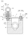
- FIG. 1 is a schematic cross-sectional view schematically showing a fixture in the first embodiment.
- FIG. 2 is a schematic cross-sectional view schematically showing the fixture in the first embodiment.
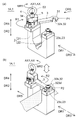
- FIG. 3 is a schematic perspective view schematically showing the fixture in the first embodiment.
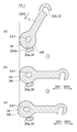
- FIG. 4 is a schematic plan view schematically showing the fixture in the first embodiment.
- FIG. 5 is a diagram schematically showing an example of the arrangement relationship between the lever and the rotation guide.
- FIG. 6 is a diagram schematically showing another example of the arrangement relationship between the lever and the rotation guide.
- FIG. 7 is a schematic cross-sectional view schematically showing part of the fixture in the first embodiment.
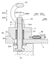
- FIG. 8 is a schematic cross-sectional view schematically showing a portion of the fixture in the first modified example of the first embodiment.
- FIG. 9 is a schematic cross-sectional view schematically showing part of a fixture in a second modified example of the first embodiment.
- FIG. 10 is a schematic two-sided view schematically showing an example of a lever.
- FIG. 11 is a schematic perspective view schematically showing an example of a lever.
- FIG. 12 is a schematic cross-sectional view schematically showing part of the fixture in the first embodiment.
- FIG. 13 is a schematic cross-sectional view schematically showing part of a fixture in a third modified example of the first embodiment;
- FIG. 14 is a schematic cross-sectional view schematically showing a fixture in a fourth modified example of the first embodiment;
- FIG. 15 is a schematic perspective view schematically showing a fixture in a fifth modified example of the first embodiment;
- FIG. 16 is a schematic perspective view schematically showing a fixture in the second embodiment.
- FIG. 17 is a schematic cross-sectional view schematically showing a fixture in the second embodiment.
- FIG. 18 is a schematic cross-sectional view schematically showing a fixture in the second embodiment.
- FIG. 19 is a schematic perspective view schematically showing an example of a lever.
- FIG. 20 is a schematic perspective view schematically showing a fixture in the first modified example of the second embodiment.
- FIG. 21 is a schematic front view schematically showing a wire cutting tool according to the third embodiment.
- FIG. 22 is a flow chart showing an example of a fixing method according to the embodiment.
- the fixture 1, the wire cutting tool 100, and the fixing method in the embodiment will be described in detail below with reference to the drawings.
- members having the same type of function are given the same or similar reference numerals. Further, repetitive descriptions of members denoted by the same or similar reference numerals may be omitted.
- first direction DR1 A direction opposite to the first direction DR1 is defined as a third direction DR3.
- the direction in which the pressing member 4 moves toward the lever 3 is defined as a second direction DR2. Also, the opposite direction of the second direction DR2 is defined as a fourth direction DR4.
- the direction from the distal end portion 31 of the lever 3 to the proximal end portion 34 of the lever 3 is defined as a fifth direction DR5.
- the fifth direction DR5 is parallel to the first direction DR1.
- FIG. 1 and 2 are schematic cross-sectional views schematically showing a fixture 1A according to the first embodiment.
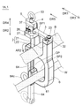
- FIG. 3 is a schematic perspective view schematically showing the fixture 1A in the first embodiment.
- FIG. 4 is a schematic plan view schematically showing the fixture 1A in the first embodiment.
- FIG. 5 is a diagram schematically showing an example of the arrangement relationship between the lever 3 and the rotation guide 26.
- FIG. 6 is a diagram schematically showing another example of the arrangement relationship between the lever 3 and the rotation guide 26.
- FIG. 7 is a schematic cross-sectional view schematically showing part of the fixture 1A in the first embodiment.
- FIG. 1 and 2 are schematic cross-sectional views schematically showing a fixture 1A according to the first embodiment.
- FIG. 3 is a schematic perspective view schematically showing the fixture 1A in the first embodiment.
- FIG. 4 is a schematic plan view schematically showing the fixture 1A in the first embodiment.
- FIG. 5 is a diagram schematically showing an example of the arrangement relationship between the lever 3 and the
- FIG. 8 is a schematic cross-sectional view schematically showing part of a fixture 1A in the first modified example of the first embodiment.
- FIG. 9 is a schematic cross-sectional view schematically showing part of a fixture 1A in a second modified example of the first embodiment.
- FIG. 10 is a schematic two-sided view schematically showing an example of the lever 3. As shown in FIG. The upper side of FIG. 10 shows a schematic plan view, and the lower side of FIG. 10 shows a cross-sectional view of the lever 3 (more specifically, a cross-sectional view taken along line AA).
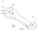
- FIG. 11 is a schematic perspective view schematically showing an example of the lever 3.
- FIG. 12 is a schematic cross-sectional view schematically showing part of the fixture 1A in the first embodiment.
- FIG. 13 is a schematic cross-sectional view schematically showing part of a fixture 1A in a third modified example of the first embodiment.
- FIG. 14 is a schematic cross-sectional view schematically showing fixture 1A in the fourth modification of the first embodiment.
- FIG. 15 is a schematic perspective view schematically showing a fixture 1A in the fifth modified example of the first embodiment.
- a fixture 1A in the first embodiment includes a gripping member 2 capable of gripping an object B, a lever 3, a pressing member 4, and an operating member 5.
- the gripping member 2 has a first gripping portion 21 and a second gripping portion 22 .
- the fixture 1A is fixed to the object B by gripping the object B with the first gripping portion 21 and the second gripping portion 22 .
- the lever 3 can pull the second gripping portion 22 in the first direction DR1 toward the first gripping portion 21 .
- the distance between the first gripping portion 21 and the second gripping portion 22 is reduced.
- the gripping member 2 (for example, the area indicated by the arrow AR) is elastically deformed to reduce the distance between the first gripping portion 21 and the second gripping portion 22 .
- the gripping member 2 as a whole may be elastically deformed.
- the pressing member 4 presses the lever 3 by moving in a second direction DR2 different from the first direction DR1.
- the second direction DR2 is a direction perpendicular to the first direction DR1.
- the pressing member 4 moves the lever 3 in the first direction DR1 by pressing the lever 3 .
- the pressing member 4 has a pressing portion 42 that presses the pressed portion 35 of the lever 3 .
- the pressing force with which the pressing portion 42 presses the pressed portion 35 has a force component F1 in the first direction DR1 in addition to the force component in the second direction DR2. Therefore, when the pressing portion 42 presses the pressed portion 35, the lever 3 moves in the first direction DR1.
- the operation member 5 has an operation portion 53 operated by a tool such as a remote control tool or by a user's hand. Further, the operating member 5 moves the pressing member 4 in the second direction DR2. In the example illustrated in FIG. 1 , the operating member 5 has a second contact portion 52 that contacts the first contact portion 44 of the pressing member 4 . When the operation portion 53 is operated in the first operation direction MR1, the second contact portion 52 presses the first contact portion 44 in the second direction DR2. As a result, the pressing member 4 moves in the second direction DR2.
- the fixture 1A can be easily fixed to the object B by utilizing the movement of the pressing member 4 and the lever 3.
- the moving direction (more specifically, the second direction DR2) of the pressing member 4 moved by the operation of the operating portion 53 differs from the moving direction of the lever 3 (more specifically, the first direction DR1). Therefore, the degree of freedom of arrangement of the operation unit 53 is high.
- the operation part 53 is rotatable around the operation axis AX, and the extending direction of the operation axis AX is perpendicular to the first direction DR1.
- FIG. 2 the example shown in FIG.
- the operation part 53 is arranged on the opposite side of the space SP1 in which the object B to be grasped by the grasping member 2 is arranged with respect to the plane PL passing through the lever 3 .
- the arrangement of the operating portion 53 in the fixture 1A is not limited to the example shown in FIG.
- the lever 3 is rotatable around the first axis AX1. More specifically, the lever 3 can move from the first position P1 to the second position P2 by rotating the lever 3 about the first axis AX1 in the first rotation direction R1. As illustrated in FIG. 3( a ), at the first position P1, the engagement between the first engaging portion 32 of the lever 3 and the second engaging portion 23 of the second grip portion 22 is released. corresponds to the position. Further, as illustrated in FIG. 3B, the second position P2 corresponds to the position where the first engaging portion 32 of the lever 3 and the second engaging portion 23 of the second grip portion 22 are engaged. do.
- the object B in other words, the object to be gripped
- the gripping member 2 can be removed from the object B.
- the fixture 1A is prevented from falling off from the object B (in other words, the grasped object).
- the lever 3 is moved in the first direction DR1 by operating the operation portion 53 in the first operation direction MR1. It is configured. More specifically, in the example shown in FIG. 1, when the operating member 5 is operated in the first operating direction MR1, the operating member 5 moves the pressing member 4 in the second direction DR2. When the pressing member 4 moves in the second direction DR2, the lever 3 moves in the first direction DR1 different from the second direction DR2. When the lever 3 moves in the first direction DR1, the lever 3 pulls the second gripping portion 22 in the first direction DR1, reducing the distance between the first gripping portion 21 and the second gripping portion 22 (see FIG. 2). ).
- the first engaging portion 32 and the second engaging portion 23 can be engaged with each other only by operating the operating portion 53 in the first operating direction MR1, and , the lever 3 can be moved in the first direction DR1.
- the lever 3 pulls the second grip portion 22 in the first direction DR1.
- the second gripping portion 22 pulled in the first direction DR1 is displaced toward the first gripping portion 21 (see FIG. 2).
- the work of fixing the fixture 1A to the object B can be carried out efficiently and easily.
- the fixture 1A includes a rotation guide 26 that guides the rotation of the lever 3 around the first axis AX1.
- the rotation guide 26 allows the lever 3 to move in the first direction DR1 in a state in which the longitudinal direction of the lever 3 is parallel to the first direction DR1. placed in an unobstructed position.
- the first engaging portion 32 provided at the distal end portion 31 of the lever 3 also moves in the first direction DR1 (see FIG. 4B). 4(c).).
- the second engaging portion 23 that engages with the first engaging portion 32 is pulled in the first direction DR1.
- the rotation guide 26 contacts the outer peripheral surface 34t of the base end portion 34 of the lever 3.
- the rotation guide 26 includes a first rotation guide 26a that contacts the outer peripheral surface 34t of the base end portion 34 of the lever 3, and a second rotation guide 26b that contacts the outer peripheral surface 34t of the base end portion 34 of the lever 3. good too.
- the rotation guide 26 includes the first rotation guide 26a and the second rotation guide 26b, the lever 3 is rotated along the first axis AX1 with the central portion of the base end portion 34 of the lever 3 positioned on the first axis AX1. can be rotated around.
- the outer peripheral surface of the first rotation guide 26a in the cross section perpendicular to the first axis AX1, has a curved shape 261a convex toward the outer peripheral surface 34t of the base end portion 34 of the lever 3.
- the outer peripheral surface of the second rotation guide 26b has a convex curved shape 261b toward the outer peripheral surface 34t of the base end portion 34 of the lever 3 .
- the outer peripheral surface of the first rotation guide 26a may have a circular shape
- the outer peripheral surface of the second rotation guide 26b may have a circular shape.
- the rotation guide 26 (more specifically, the first rotation guide 26a and/or the second rotation guide 26b) includes a guide support portion 262 and a guide support portion 262. It may have a rotatable roller 263 . Alternatively, the rotation guide 26 may be fixed to the guide support such that it cannot rotate relative to the guide support.
- the rotation guide 26 may have an arcuate surface 264a complementary to the outer peripheral surface 34t of the base end portion 34 of the lever 3, as illustrated in FIG. 6(a).
- the rotation guide 26 is composed only of the first rotation guide 26a.
- the fixture 1A has two rotation guides (26a, 26b), and in the example shown in FIG. 6A, the fixture 1A has rotation guides ( 26a) is one.
- the fixture 1A may have three or more rotation guides.
- the outer peripheral surface 34t of the base end portion 34 of the lever 3 when viewed in the direction along the first axis AX1, is an arc centered on the first axis AX1. composed of faces.
- the rotation guide 26 smoothly guides the outer peripheral surface 34 t of the base end portion 34 .
- the pressing member 4 has a pressing portion 42 that presses the pressed portion 35 of the lever 3 .
- the pressing portion 42 has a shape capable of pressing the pressed portion 35 in both the first direction DR1 and the second direction DR2. In this case, when the pressing portion 42 presses the pressed portion 35, the pressing force by the pressing portion 42 has a force component in the first direction DR1 and a force component in the second direction DR2. Therefore, when the pressing portion 42 presses the pressed portion 35, the pressing portion 42 can move the pressed portion 35 in the first direction DR1.
- the pressing member 4 includes a block 40 that can move relative to the lever 3 in a direction parallel to the second direction DR2.
- the block 40 and the pressing portion 42 may be integrally formed.
- the pressing portion 42 may be attached to a block 40 that is relatively movable with respect to the lever 3 in a direction parallel to the second direction DR2.
- the pressing member 4 has a through-hole portion 45h into which a shaft 55, which will be described later, is inserted. Further, the pressing member 4 may have a recess 46d that receives a first biasing member 81, which will be described later.
- First inclined surface 421 and/or second inclined surface 352 In the example illustrated in FIG. 7 , at least one of the pressing portion 42 and the pressed portion 35 applies the pressing force with which the pressing portion 42 presses the pressed portion 35 to a force component in the first direction DR1 and a force component in the second direction DR2. It has an inclined surface (421, 352) that decomposes into force components.
- the pressing member 4 has a first inclined surface 421 that presses the pressed portion 35 .
- the first inclined surface 421 decomposes the pressing force with which the pressing member 4 presses the lever 3 into a force component in the second direction DR2 and a force component in the first direction DR1.
- the first inclined surface 421 is an inclined surface that faces the second direction DR2 as it approaches the operation axis AX.
- the first inclined surface 421 may have a linear shape S1 or a curved shape.
- the first inclined surface 421 may be configured by a flat surface, or may be configured by a curved surface.
- the pressed portion 35 of the lever 3 has a second inclined surface 352 that is pressed by the pressing member 4 .
- the second inclined surface 352 decomposes the pressing force with which the pressing member 4 presses the lever 3 into a force component in the second direction DR2 and a force component in the first direction DR1.
- the second inclined surface 352 is an inclined surface that faces the second direction DR2 as it approaches the operation axis AX.
- the second inclined surface 352 may have a linear shape S2 or a curved shape.
- the pressing portion 42 of the pressing member 4 has a first inclined surface 421 that presses the pressed portion 35 , and the pressed portion 35 is a second inclined surface that is pressed by the pressing portion 42 . 352.
- one of the pressing portion 42 and the pressed portion 35 has an inclined surface
- the other of the pressing portion 42 and the pressed portion 35 has an arbitrary shape that contacts the inclined surface. It's okay.
- the pressed portion 35 has an inclined surface (more specifically, the second inclined surface 352)
- the tip of the pressing portion 42 has the inclined surface (more specifically, the , second inclined surface 352).
- the pressing portion 42 may have an inclined surface (more specifically, the first inclined surface 421)
- the pressed portion 35 may have a hemispherical surface that contacts the inclined surface.
- the pressed portion 35 has an inclined surface (more specifically, a second inclined surface 352)
- the pressing portion 42 has an inclined surface (more specifically, a second inclined surface 352).
- the roller 428 is supported by the body portion (more specifically, the block 40) of the pressing member 4 so as to be rotatable around the rotation axis AT.
- the pressing portion 42 may have an inclined surface (more specifically, the first inclined surface 421), and the pressed portion 35 may have a roller that contacts the inclined surface.
- lever 3 In the example shown in FIG. 2, the lever 3 has a distal end 31 and a proximal end 34 .
- a base end portion 34 of the lever 3 has a pressed portion 35 that is pressed by the pressing portion 42 of the pressing member 4 .
- the lever 3 has a second guide 37 that guides the relative movement of the lever 3 with respect to the pressing member 4 in the first direction DR1.
- the second guide 37 is two protrusions 37a and 37b arranged on both sides of the pressing member 4.
- the pressing member 4 may have a second guide that guides the relative movement of the lever 3 with respect to the pressing member 4 in the first direction DR1.
- the pressing member 4 may have two protrusions arranged on either side of the lever 3 .
- the second guide 37 has a protrusion disposed on one of the lever 3 and the pressing member 4 and a recess, groove, or long groove disposed on the other of the lever 3 and the pressing member 4. It may have a hole. In this case, the relative movement of the lever 3 in the first direction DR1 with respect to the pressing member 4 is guided by the projection, the recess, the groove, or the long hole.
- the second guide 37 may prevent the lever 3 from rotating relative to the pressing member 4 around the first axis AX1.
- a relative rotation preventing portion different from the second guide 37 may prevent relative rotation of the lever 3 with respect to the pressing member 4 .
- the lever 3 (more specifically, the tip 31 of the lever 3) has a first engaging portion 32, and the second grip portion 22 has a first engaging portion. It has a second engaging portion 23 that can be engaged with the portion 32 .
- the first engaging portion 32 is an engaging hook 32k.
- the engaging hook 32k has, for example, a substantially C shape.
- the second engaging portion 23 includes an elongated member 23c (for example, a screw member, a pin member, or a screw member and a collar rotatable relative to the screw member). It is composed by
- the engaging hook 32k includes a first opening edge 321 on the distal end portion 31 side, a second opening edge 322 on the base end portion 34 side, and It has a C-shaped inner edge 323 connecting the first opening edge 321 and the second opening edge 322 .
- the C-shaped inner edge 323 preferably has a recess 323 d that is recessed closer to the distal end 31 than the first opening edge 321 . In this case, when the second engaging portion 23 of the second grip portion 22 is engaged with the recess 323d, the second engaging portion 23 is less likely to come off from the recess 323d (see FIG. 3B).
- each of the first opening edge 321 and the second opening edge 322 is a substantially linear opening edge when viewed in a direction parallel to the second direction DR2. Also, the second opening edge 322 and the C-shaped inner edge 323 are smoothly connected. In this case, the engagement hook 32k can be smoothly removed from the second engagement portion 23 by rotating the lever 3 in the second rotation direction R2 around the first axis AX1.
- the fixture 1A has a shaft 55 that supports the operating member 5. As shown in FIG. The shaft 55 extends along the first axis AX1.
- the lever 3 has an elongated hole 33h into which the shaft 55 is inserted.
- the long hole portion 33h allows the lever 3 to move relative to the shaft 55 in a direction parallel to the first direction DR1. As illustrated in FIG. 10, the long axis of the elongated hole 33h is preferably parallel to the longitudinal direction of the lever 3. As shown in FIG.
- the shaft 55 When the shaft 55 is inserted into the elongated hole 33h, the shaft 55 may function as a rotation guide that guides the rotation of the lever 3 about the first axis AX1 from the inside (see the dashed line in FIG. 10).
- An inner surface 331 h of the long hole portion 33 h on the base end portion 34 side is preferably an arcuate surface having a shape complementary to the outer surface of the shaft 55 .
- the shaft 55 has a shaft body 550 and a collar 551 arranged between the shaft body 550 and the long hole portion 33h.
- the collar 551 reduces the frictional force that the long hole portion 33h receives from the shaft 55 when the lever 3 rotates around the first axis AX1.
- the fixture 1A has a support portion 27 that supports the lever 3 .
- the support portion 27 is attached to the first grip portion 21 .
- the support portion 27 and the first grip portion 21 may be integrally formed.
- the support portion 27 may be part of the first grip portion 21 .
- the support portion 27 may be formed with a hole portion 27h into which a portion of the shaft 55 can be inserted.
- the fixture 1A comprises a washer 71 arranged between the support 27 and the lever 3.
- the washer 71 reduces the frictional force that the lever 3 receives from the support portion 27 when the lever 3 rotates around the first axis AX1. More specifically, the washer 71 reduces the frictional force between the lever 3 and the washer 71 compared to the frictional force between the operating member 5 and the pressing member 4 . Therefore, when the fixture 1A includes the washer 71, slippage between the operating member 5 and the pressing member 4 is less likely to occur when the operating portion 53 is operated in the first operating direction MR1.
- the washer 71 is preferably a thrust washer that supports the load in the second direction DR2 received from the lever 3 .
- the fixture 1A includes a first biasing member 81 that biases the pressing member 4 toward the operating member 5 .
- the first biasing member 81 moves the pressing member 4 relative to the lever 3 in the fourth direction DR4.
- the lever 3 can move in the third direction DR3.
- the pulling force acting on the second gripping portion 22 from the lever 3 is released (in other words, the gripping of the object B by the gripping member 2 is released. ).
- the first biasing member 81 increases the frictional force between the pressing member 4 and the operating member 5 . Therefore, when the operating portion 53 is operated in the first operating direction MR1, slippage between the pressing member 4 and the operating member 5 is less likely to occur. Thus, when the operation portion 53 is operated in the first operation direction MR1, the pressing member 4 and the lever 3 rotate in the first rotation direction R1 (see FIG. 3A), and the lever 3 is moved to the first position. It moves smoothly from P1 to the second position P2 (see FIG. 3(b)).
- the operating member 5 has an operating portion 53 rotatable around the operating axis AX.
- the operating axis AX coincides with the first axis AX1 (in other words, the rotation axis of the lever 3).
- the operating portion 53 has a through hole portion 53h into which a tool such as a remote control tool can be inserted.
- the operating portion 53 is an annular operating portion.
- the operating member 5 has a female screw portion 5f that screws together with the male screw portion 55m of the shaft 55.
- the operating member 5 moves relative to the shaft 55 in the second direction DR2.
- the operating member 5 presses the pressing member 4 in the second direction DR2.
- the operating member 5 and the shaft 55 may be integrally configured to be rotatable around the operating axis AX.
- the operation member 5 and the shaft 55 are integrated. , and may be configured to rotate relative to the support portion 27 .
- the fixture 1A moves the lever 3 in the fifth direction DR5 (in other words, the direction from the distal end portion 31 to the proximal end portion 34) or in the direction opposite to the fifth direction DR5. It may have a second biasing member 85 that biases in the direction.
- the fixture 1A includes the second biasing member 85 that biases the lever 3 in the fifth direction DR5
- the first engagement of the lever 3 occurs when the operating portion 53 is operated in the second operating direction MR2. Unintentional disengagement of the portion 32 from the second engaging portion 23 of the second gripping portion 22 is prevented or suppressed.
- the fixture 1A includes the second biasing member 85 that biases the lever 3 in the direction opposite to the fifth direction DR5
- the operating portion 53 is operated in the second operating direction MR2
- the first engaging portion 32 of the lever 3 is easily disengaged from the second engaging portion 23 of the second grip portion 22 .
- Whether to make the first engaging portion 32 difficult to come off from the second engaging portion 23 or to make the first engaging portion 32 easy to come off from the second engaging portion 23 depends, for example, on the fixture 1A. Selection is made according to the type of object B and the like.
- the second biasing member 85 is arranged between the lever 3 and the pressing member 4 .
- the gripping member 2 has a notch 28 that assists the elastic deformation of the second gripping portion 22 toward the first gripping portion 21 .
- the notch 28 is arranged, for example, so as to face the space SP1 in which the object B is arranged.
- the gripping member 2 may be connected to In the example illustrated in FIG. 14 , the second gripping portion 22 is connected to the first gripping portion 21 via a hinge 29 .
- the fixture 1A has a wire receiving portion 6 capable of receiving the wire W.
- the wire receiving portion 6 has a receiving portion main body 61 and an opening/closing member 64 .
- the receiving portion main body 61 defines a space SP2 in which the electric wire W is arranged. Further, the receiving portion main body 61 has an opening OP through which the electric wire W can pass.
- the opening/closing member 64 can open and close the opening OP.
- the opening/closing member 64 has a second operating portion 64c for opening/closing the opening/closing member 64 .
- the electric wire W can be inserted into the space SP2 through the opening OP.
- the electric wire W can be removed from the space SP2 through the opening OP.
- the opening/closing member 64 is in the closed position (see the opening/closing member 64 indicated by the solid line in FIG. 15)
- the wire W is surrounded by the receiving portion main body 61 and the opening/closing member 64 . Therefore, the electric wire W does not come off from the electric wire receiving portion 6.
- the wire W arranged in the wire receiving portion 6 is positioned within a predetermined range by fixing the fixture 1A to the object B.
- the relative position of the wire W to the object B can be changed. can be done.
- the object B is, for example, an extendable rod member.
- FIG. 16 is a schematic perspective view schematically showing fixture 1B in the second embodiment.
- 17 and 18 are schematic cross-sectional views schematically showing fixture 1B in the second embodiment.
- FIG. 19 is a schematic perspective view schematically showing an example of the lever 3.
- FIG. 20 is a schematic perspective view schematically showing a fixture 1B in the first modified example of the second embodiment.
- the fixture 1B in the second embodiment differs from the fixture 1A in the first embodiment in that the lever 3 cannot rotate around the first axis AX1. Otherwise, the second embodiment is similar to the first embodiment.
- a fixture 1B in the second embodiment includes (1) a gripping member 2 having a first gripping portion 21 and a second gripping portion 22 and capable of gripping an object B; 2) the lever 3 capable of pulling the second grip portion 22 in a first direction DR1 toward the first grip portion 21; and (4) an operating member 5 having an operating portion 53 and moving the pressing member 4 in a second direction DR2. and
- the fixture 1B can be easily fixed to the object B by using the movement of the pressing member 4 and the lever 3.
- the moving direction (more specifically, the second direction DR2) of the pressing member 4 moved by the operation of the operating portion 53 differs from the moving direction of the lever 3 (more specifically, the first direction DR1). Therefore, the degree of freedom of arrangement of the operation unit 53 is high.
- the operation part 53 is not necessary to arrange the operation part 53 on the extension line of the lever 3 in the longitudinal direction.
- the operation portion 53 is rotatable around the operation axis AX, and the extending direction of the operation axis AX is perpendicular to the first direction DR1.
- FIG. 17 the example illustrated in FIG.
- the operation part 53 is arranged on the opposite side of the space SP1 in which the object B to be grasped by the grasping member 2 is arranged with respect to the plane PL passing through the lever 3 .
- the arrangement of the operating portion 53 in the fixture 1B is not limited to the examples shown in FIGS. 17 and 18.
- FIG. 17 the arrangement of the operating portion 53 in the fixture 1B is not limited to the examples shown in FIGS. 17 and 18.
- the lever 3 (more specifically, the tip 31 of the lever 3) has a first engagement portion 32 that engages the second engagement portion 23 of the second grip portion 22.
- the first engaging portion 32 is an engaging hole portion 32h.
- the engaging hole 32h is preferably an elongated hole having a long axis along the longitudinal direction of the lever 3. As shown in FIG.
- the second gripping portion 22 has a second engaging portion 23 that engages the first engaging portion 32 of the lever 3 .
- the second engaging portion 23 preferably has a shape that can be inserted into the engaging hole portion 32h.
- the second engaging portion 23 may be configured by an elongated member 23c such as a screw member or a pin member. Alternatively, the second engaging portion 23 may be formed by cutting a part of the second gripping portion 22 .
- first engaging portion 32 and the second engaging portion 23 is an engaging concave portion
- the other of the first engaging portion 32 and the second engaging portion 23 is an engaging convex portion.
- the first engaging portion 32 and the second engaging portion 23 may have any shape as long as they can be engaged with each other.
- the fixture 1B includes a wire receiving portion 6 capable of receiving the wire W.
- the wire receiving portion 6 has a receiving portion main body 61 and an opening/closing member 64 .
- the receiving portion main body 61 defines a space SP2 in which the electric wire W is arranged. Further, the receiving portion main body 61 has an opening portion OP through which an electric wire can pass.
- the opening/closing member 64 can open and close the opening OP.
- the opening/closing member 64 has a second operating portion 64c for opening/closing the opening/closing member 64 .
- the electric wire W can be inserted into the space SP2 through the opening OP.
- the electric wire W can be removed from the space SP2 through the opening OP.
- the opening/closing member 64 is in the closed position, the wire W is surrounded by the receiving portion main body 61 and the opening/closing member 64 . Therefore, the electric wire W does not come off from the electric wire receiving portion 6.
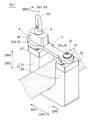
- FIG. 21 is a schematic front view schematically showing the wire cutting tool 100 according to the third embodiment.
- the points different from the first and second embodiments will be mainly described. omitted. Therefore, even if not explicitly described in the third embodiment, it goes without saying that the matters already described in the first embodiment or the second embodiment can be adopted in the third embodiment. .
- a wire cutting tool 100 according to the third embodiment includes a fixture 1, a bar member 110, a first wire gripper 120, and a second wire gripper 130.
- the object B mentioned above is a bar member 110 .
- the fixture 1A in the first embodiment may be adopted
- the fixture 1B in the second embodiment may be adopted
- others. of fasteners may be employed.
- the fixture 1 has (1) a first gripping portion 21 and a second gripping portion 22, and has a gripping member 2 that grips the rod member 110, and (2) a second gripping portion 22 that faces the first gripping portion 21. (3) the lever 3 is pushed by moving in a second direction DR2 different from the first direction DR1; (4) an operating member 5 having an operating portion 53 and moving the pressing member 4 in a second direction DR2; and (5) a wire receiving portion 6.
- the wire receiving portion 6 defines a space SP2 in which the wire W is arranged, and includes a receiving portion main body 61 having an opening OP, and an opening/closing member 64 capable of opening and closing the opening OP.
- the bar member 110 is gripped by the gripping member 2 .
- the fixture 1 is fixed to the rod member 110 while the rod member 110 is gripped by the gripping member 2 .
- the electric wire W arranged in the electric wire receiving portion 6 is positioned within a predetermined range.
- the fixture 1 can rotate around the longitudinal axis L1 of the rod member 110 when the gripping member 2 has loosened the grip of the rod member 110 . Rotation of the fixture 1 around the longitudinal axis L1 of the rod member 110 changes the position of the wire arranged in the wire receiving portion 6 .
- the rod member 110 be stretchable in the direction along the longitudinal axis L1.
- the distance between the first wire gripper 120 and the second wire gripper 130 can be changed by extending and retracting the rod member 110 .
- the first wire gripper 120 is arranged at the first end 110 a of the bar member 110 .
- the first wire gripper 120 grips the first portion of the wire W. As shown in FIG.
- the second wire gripper 130 is arranged at the second end portion 110b of the bar member 110 .
- the second wire gripper 130 grips the second portion of the wire W. As shown in FIG.
- the rod member 110 With the first wire gripper 120 gripping the first portion of the wire W and the second wire gripper 130 gripping the second portion of the wire W, the rod member 110 is moved along the longitudinal axis L1 of the rod member. Shrinking in the longitudinal direction reduces the distance between the first wire gripper 120 and the second wire gripper 130 . As a result, the portion of the wire W located between the first wire gripper 120 and the second wire gripper 130 is loosened.
- the rod member 110 includes an outer member 111, an inner member 112, and an operating portion 113.
- the operation part 113 is a part for operating the relative movement of the inner member 112 with respect to the outer member 111 .
- the operating portion 113 is connected to the rod member 110 and is rotatable around the second axis AX2.
- the operating portion 113 includes an engaging portion 113c with which the distal end of the remote control member engages.
- the operating portion 113 is provided with a first bevel gear that rotates around the second axis AX2 together with the operating portion, and (B) the outer member 111 is connected to the first bevel gear so as to be capable of transmitting load.
- the second bevel gear rotates about the longitudinal axis L1 of the rod member 110 with a threaded rod having external threads disposed on its outer periphery;
- the inner member 112 is screwed into the threaded rod.
- the first bevel gear rotates around the second axis AX2 and the second bevel gear rotates around the longitudinal axis L1 of the rod member 110. to rotate.
- Rotation of the second bevel gear about the longitudinal axis L1 causes the threaded rod to rotate about the longitudinal axis L1.
- the inner member 112 threadedly engaged with the threaded rod moves in a direction to be pulled into the outer member 111 .
- the bar member 110 contracts.
- the mechanism for contracting the rod member 110 is not limited to the mechanism described above.
- the wire cutting operation and the wire is executed.
- the slack portion of wire W is cut by any cutting tool.
- the wire W is formed with a first cut end and a second cut end.
- the first cut end and the second cut end are sorted (for example, sorted vertically).
- the above steps (more specifically, the first wire gripper 120 grips the first portion of the wire W and the second wire gripper 130 grips the second portion of the wire W, and the bar member 110 is contracted the step of contracting, the step of cutting the loose portion of the electric wire W formed by the contraction of the rod member 110 with a cutting tool, and the step of distributing the first cut end portion and the second cut end portion formed by the cutting), Wire cutting work is completed.
- the wire cutting tool 100 includes the above-described fixture 1 having the wire receiving portion 6 from the viewpoint of efficiently performing the work of separating the first cut end portion and the second cut end portion.
- the wire receiving portion 6 receives the wire W in the region between the first wire gripper 120 and the second wire gripper 130 and positions the wire W within a predetermined range.
- the fixture 1 When sorting the first cut end and the second cut end of the electric wire, for example, in a state where the electric wire connected to the first cut end is arranged in the space SP2 defined by the electric wire receiving portion 6, the fixture 1 can be rotated around the longitudinal axis L1 of the rod member 110 .
- the wire cutting tool 100 in the third embodiment may include a second fixture 1' in addition to the fixture 1.
- the fixture 1A in the first embodiment may be employed
- the fixture 1B in the second embodiment may be employed, or other fixtures may be employed. .
- FIG. FIG. 22 is a flow chart showing an example of a fixing method according to the embodiment.
- the fixture 1 used in the fixing method in the embodiment may be the fixture 1A in the first embodiment, the fixture 1B in the second embodiment, or other fixtures. may be
- the fixture 1 includes (1) a gripping member 2 having a first gripping portion 21 and a second gripping portion 22, (2) a lever 3, (3) a pressing member 4 capable of pressing the lever 3, and (5) and an operation member 5 having an operation portion 53 .
- the gripping member 2, the lever 3, the pressing member 4, and the operating member 5 have already been described in the first embodiment, the second embodiment, and the third embodiment. other explanations are omitted.
- the fixture 1 with the object B arranged between the first gripping part 21 and the second gripping part 22 is prepared.
- the first step ST1 is a preparatory step.
- the object B placed between the first gripping part 21 and the second gripping part 22 is a bar member (for example, the first wire gripper 120 is placed at the first end 110a, and the second wire gripper 130 is It may be a bar member 110) disposed at the second end 110b, or may be a member of another shape.
- the fixture 1 in which the object B is placed in advance may be prepared between the first gripping part 21 and the second gripping part 22 .
- the object B is placed in advance between the first gripping portion 21 and the second gripping portion 22, and the first engaging portion 32 of the lever 3 and the second gripping portion 22 of the second gripping portion 22 are arranged.
- a fixture 1B in a state of being engaged with the engaging portion 23 is prepared.
- the fixture 1 and the object B may be separately prepared, and then the object B may be placed between the first gripping portion 21 and the second gripping portion 22.
- a fixture 1A in which the object B is not arranged between the first gripping portion 21 and the second gripping portion 22 is prepared, and then the first gripping portion 21 and the second gripping portion 21 are prepared.
- the object B is placed between the holding portion 22 and the first engaging portion 32 of the lever 3 and the second engaging portion 23 of the second holding portion 22 are engaged (Fig. 3(b)). ).
- the engagement between the first engaging portion 32 and the second engaging portion 23 is performed by operating the operating portion 53 in the first operating direction MR1. . More specifically, when the operating portion 53 is operated in the first operating direction MR1 around the operating axis AX1, the lever 3 rotates in the first rotational direction R1 around the first axis AX1. By rotating the lever 3 in the first rotation direction R1, the lever 3 is moved to the first position P1 (see FIG. 3 ( a)) to the second position P2 (see FIG. 3B) where the first engaging portion 32 and the second engaging portion 23 are engaged with each other.
- the pressing member 4 is moved in the second direction DR2 by operating the operating portion 53.
- the second step ST2 is a pressing member moving step.
- the operating portion 53 is operated in the first operating direction MR1.
- the pressing member 4 moves in the second direction DR2. More specifically, when the operating portion 53 is operated in the first operating direction MR1 about the operating axis AX, the operating member 5 moves in the second direction DR2, and the operating member 5 pushes the pressing member 4 in the second direction. Press DR2. As a result, the pressing member 4 moves in the second direction DR2.
- the operation direction of the operation portion 53 when rotating the lever 3 around the first axis AX1 is the first operation direction MR1, and in FIG. 1, the pressing member 4 is moved in the second direction DR2.
- the operation direction of the operation portion 53 when the operation is performed is the first operation direction MR1. Therefore, by operating the operation portion 53 in the first operation direction MR1, the operation of rotating the lever 3 around the first axis AX1 and the operation of moving the pressing member 4 in the second direction DR2 are simultaneously or continuously performed. is executed.
- a third step ST3 is a conversion step.
- the pressing member 4 moves toward the pressed portion 35 of the lever 3 (more specifically, the base end portion 34 of the lever 3).
- the provided pressed portion 35) is pressed.
- the pressing force with which the pressing member 4 presses the lever 3 has a force component in the second direction DR2 and a force component F1 in the first direction DR1.
- the force component F1 in the first direction DR1 acts on the lever 3, the lever 3 moves in the first direction DR1.
- the pressing member 4 has a first inclined surface 421 that presses the pressed portion 35 .
- the first inclined surface 421 decomposes the pressing force with which the pressing member 4 presses the lever 3 into a force component in the second direction DR2 and a force component in the first direction DR1.
- the pressed portion 35 of the lever 3 has a second inclined surface 352 that is pressed by the pressing member 4. As shown in FIG.
- the second inclined surface 352 decomposes the pressing force with which the pressing member 4 presses the lever 3 into a force component in the second direction DR2 and a force component in the first direction DR1.
- a fourth step ST4 is a displacement step. In the displacement step, the second gripping portion 22 is displaced toward the first gripping portion 21 by the lever 3 pulling the second gripping portion 22 in the first direction DR1.
- the movement of the lever 3 in the first direction DR1 causes the first engaging portion 32 of the lever 3 to move the second engaging portion 23 of the second gripping portion 22 to the first position. Pull in direction DR1.
- the second gripping portion 22 is displaced toward the first gripping portion 21 .
- the displacement of the second gripping portion 22 in the direction toward the first gripping portion 21 may be achieved by elastic deformation of the gripping member 2, as illustrated in FIG.
- the displacement of the second gripping portion 22 in the direction toward the first gripping portion 21 is such that the second gripping portion 22 is hinged 29 relative to the first gripping portion 21, as illustrated in FIG. It may be realized by rotating about an axis.
- the object B is gripped by the first gripping part 21 and the second gripping part 22 displaced toward the first gripping part 21.
- the fixture 1 is fixed to the object B in this way.
- the fixture 1 can be easily fixed to the object B by operating the operating portion 53 in the first operating direction MR1.
- the fixing method in the embodiment may include a second fixing step (sixth step ST6) of fixing the fixture 1 to the object B.
- the second fixing step includes a grip release step (sub-step ST6-1) of releasing the grip of the object B by the first gripping unit 21 and the second gripping unit 22, and a posture of changing the posture of the fixture 1 with respect to the object B.
- the grip release step (in other words, sub-step ST6-1) is executed by operating the operation unit 53.
- the operation portion 53 is operated in the second operation direction MR2 (more specifically, the direction opposite to the first operation direction MR1) in the grip release step.
- the pressing member 4 becomes movable in the fourth direction DR4 (more specifically, the direction opposite to the second direction DR2), and the lever 3 is It becomes movable in the third direction DR3 (more specifically, the direction opposite to the first direction DR1).
- the second gripping portion 22 is displaced away from the first gripping portion 21, and the gripping of the object B by the first gripping portion 21 and the second gripping portion 22 is released.
- "release of the grip” means that the posture of the fixture 1 with respect to the object B can be changed. Therefore, it does not matter if some gripping force acts on the object B from the gripping member 2 in the "released" state.
- the fixture 1 may have a first biasing member 81 that biases the pressing member 4 in the fourth direction DR4.
- the biasing force of the first biasing member 81 causes the pressing member 4 to move in the fourth direction DR4.
- the posture changing step (in other words, sub-step ST6-2) is executed by moving the fixture 1 relative to the object B (for example, rotating the fixture 1 relative to the object B).
- the posture changing step includes rotating the fixture 1 relative to the object B (more specifically, the rod member 110) around the longitudinal axis L1 of the object B.
- the first cut end of the wire positioned in the predetermined range by the fixture 1 is replaced by the wire positioned in the predetermined range by the second fixture 1' by executing the posture changing process. is diverted from the second cut end of the .
- the posture changing process may include rotating the fixture 1 around the longitudinal axis L1 of the object B using a remote control tool.
- the second object gripping process (in other words, sub-step ST6-3) is executed by operating the operation unit 53.
- the operation part 53 is operated in the first operation direction MR1 in the second object gripping step.
- the pressing member 4 moves in the second direction DR2.
- the pressing member 4 presses the pressed portion 35 of the lever 3 .
- the pressing force with which the pressing member 4 presses the lever 3 has a force component in the second direction DR2 and a force component F1 in the first direction DR1.
- the force component F1 in the first direction DR1 acts on the lever 3, the lever 3 moves in the first direction DR1.
- the lever 3 moves in the first direction DR1
- the first engaging portion 32 of the lever 3 pulls the second engaging portion 23 of the second grip portion 22 in the first direction DR1.
- the second gripping portion 22 is displaced toward the first gripping portion 21 .
- the object B is gripped again by the first gripping portion 21 and the second gripping portion 22 displaced toward the first gripping portion 21 .
- the fixing method in the embodiment it is possible to easily change the posture of the fixture 1 with respect to the object B and fix the fixture 1 to the object B again. More specifically, by operating the operation portion 53 in the second operation direction MR2, the gripping of the object B by the first gripping portion 21 and the second gripping portion 22 can be released. Further, after the posture of the fixture 1 with respect to the object B is changed, the fixture 1 can be easily fixed to the object B again by operating the operation part 53 in the first operation direction MR1.
- the fixing method in the embodiment includes a converting step of converting movement of the pressing member 4 in the second direction DR2 into movement of the lever 3 in the first direction DR1 different from the second direction DR2. Therefore, it is not always necessary to arrange the operation part 53 on the extension line of the lever 3 in the longitudinal direction, and the flexibility of the arrangement of the operation part 53 in the fixture 1 is large.
- the fixture By using the fixture, wire cutting tool, and fixing method of the present invention, the fixture can be easily fixed to an object. Therefore, it is useful to those who work to secure fasteners to objects, and to manufacturers who manufacture fasteners or wire cutting tools.
Landscapes
- Engineering & Computer Science (AREA)
- General Engineering & Computer Science (AREA)
- Mechanical Engineering (AREA)
- Clamps And Clips (AREA)
- Scissors And Nippers (AREA)
- Perforating, Stamping-Out Or Severing By Means Other Than Cutting (AREA)
Priority Applications (3)
| Application Number | Priority Date | Filing Date | Title |
|---|---|---|---|
| KR1020237042615A KR20240013144A (ko) | 2021-05-28 | 2022-03-25 | 고정구, 전선 절분 공구 및 고정방법 |
| CN202290000456.6U CN222650272U (zh) | 2021-05-28 | 2022-03-25 | 固定器以及电线切割工具 |
| JP2023524045A JP7814760B2 (ja) | 2021-05-28 | 2022-03-25 | 固定具、電線切分工具、および、固定方法 |
Applications Claiming Priority (2)
| Application Number | Priority Date | Filing Date | Title |
|---|---|---|---|
| JP2021-090369 | 2021-05-28 | ||
| JP2021090369 | 2021-05-28 |
Publications (1)
| Publication Number | Publication Date |
|---|---|
| WO2022249712A1 true WO2022249712A1 (ja) | 2022-12-01 |
Family
ID=84228669
Family Applications (1)
| Application Number | Title | Priority Date | Filing Date |
|---|---|---|---|
| PCT/JP2022/014397 Ceased WO2022249712A1 (ja) | 2021-05-28 | 2022-03-25 | 固定具、電線切分工具、および、固定方法 |
Country Status (5)
| Country | Link |
|---|---|
| JP (1) | JP7814760B2 (https=) |
| KR (1) | KR20240013144A (https=) |
| CN (1) | CN222650272U (https=) |
| TW (1) | TWI820709B (https=) |
| WO (1) | WO2022249712A1 (https=) |
Citations (6)
| Publication number | Priority date | Publication date | Assignee | Title |
|---|---|---|---|---|
| JPS4317295Y1 (https=) * | 1965-08-28 | 1968-07-18 | ||
| JPS5142124B1 (https=) * | 1970-04-11 | 1976-11-13 | ||
| JPH0583415U (ja) * | 1992-04-09 | 1993-11-12 | 不二サッシ株式会社 | 引張クランプ具 |
| US20020060456A1 (en) * | 2000-11-01 | 2002-05-23 | Linares Rodolfo A. | Spring-loaded camlock |
| JP2010051081A (ja) * | 2008-08-20 | 2010-03-04 | Nagaki Seiki Co Ltd | 架線工事用補助具及び架線工事方法 |
| CN209956565U (zh) * | 2019-03-29 | 2020-01-17 | 江苏巨弘捆带制造有限公司 | 一种能快速调节松紧的捆带 |
Family Cites Families (3)
| Publication number | Priority date | Publication date | Assignee | Title |
|---|---|---|---|---|
| JPH047605Y2 (https=) * | 1986-03-14 | 1992-02-27 | ||
| KR102212646B1 (ko) * | 2018-12-06 | 2021-02-08 | 한국전력공사 | 가공송전선로의 점퍼 분리용 바이패스 장치 |
| CN216056035U (zh) * | 2021-10-21 | 2022-03-15 | 国网陕西省电力公司铜川供电公司 | 一种针式绝缘子扶正器 |
-
2022
- 2022-03-25 CN CN202290000456.6U patent/CN222650272U/zh active Active
- 2022-03-25 JP JP2023524045A patent/JP7814760B2/ja active Active
- 2022-03-25 KR KR1020237042615A patent/KR20240013144A/ko active Pending
- 2022-03-25 WO PCT/JP2022/014397 patent/WO2022249712A1/ja not_active Ceased
- 2022-05-16 TW TW111118243A patent/TWI820709B/zh active
Patent Citations (6)
| Publication number | Priority date | Publication date | Assignee | Title |
|---|---|---|---|---|
| JPS4317295Y1 (https=) * | 1965-08-28 | 1968-07-18 | ||
| JPS5142124B1 (https=) * | 1970-04-11 | 1976-11-13 | ||
| JPH0583415U (ja) * | 1992-04-09 | 1993-11-12 | 不二サッシ株式会社 | 引張クランプ具 |
| US20020060456A1 (en) * | 2000-11-01 | 2002-05-23 | Linares Rodolfo A. | Spring-loaded camlock |
| JP2010051081A (ja) * | 2008-08-20 | 2010-03-04 | Nagaki Seiki Co Ltd | 架線工事用補助具及び架線工事方法 |
| CN209956565U (zh) * | 2019-03-29 | 2020-01-17 | 江苏巨弘捆带制造有限公司 | 一种能快速调节松紧的捆带 |
Also Published As
| Publication number | Publication date |
|---|---|
| JPWO2022249712A1 (https=) | 2022-12-01 |
| JP7814760B2 (ja) | 2026-02-17 |
| KR20240013144A (ko) | 2024-01-30 |
| CN222650272U (zh) | 2025-03-21 |
| TWI820709B (zh) | 2023-11-01 |
| TW202304092A (zh) | 2023-01-16 |
Similar Documents
| Publication | Publication Date | Title |
|---|---|---|
| JP7138245B2 (ja) | 掴み工具 | |
| US5960689A (en) | Bar puller | |
| US6983522B2 (en) | Exchange device for grip heads comprising a plurality of clamping jaws | |
| US5067472A (en) | Bow string release | |
| US20200315739A1 (en) | Releasable Attachment Device for Coupling to Medical Devices and Related Systems and Methods | |
| US20250262722A1 (en) | Locking pliers and other gripping tools | |
| US5499800A (en) | Adjustable toggle action quick release locking bar clamp | |
| WO2021176973A1 (ja) | 掴み工具 | |
| JP4188719B2 (ja) | 掴線器 | |
| JP3015352B1 (ja) | 線状体把持器 | |
| WO2022249712A1 (ja) | 固定具、電線切分工具、および、固定方法 | |
| US11664634B2 (en) | Wire operating tool and component for wire operating tool | |
| CN116269802A (zh) | 手术器械及手术机器人 | |
| JP7686292B2 (ja) | 把持工具、および、把持工具の使用方法 | |
| WO2020261638A1 (ja) | 把持工具、および、把持工具の使用方法 | |
| JP3827393B2 (ja) | 線状体把持器 | |
| US20200282524A1 (en) | Pliers Tool | |
| JP2019030955A (ja) | ロック機能付きピンセット | |
| JP6464426B2 (ja) | 把持装置 | |
| JP7287711B2 (ja) | 掴線器、および、線材切分工具 | |
| CN222884185U (zh) | 远程操作用适配器 | |
| CN112493675B (zh) | 一种可翻转键盘托架 | |
| WO2022239533A1 (ja) | 掴線器、線材切分工具、および、掴線器の使用方法 | |
| KR100672106B1 (ko) | 전동 핀셋 | |
| JP2004290459A (ja) | 内視鏡のアングル操作装置 |
Legal Events
| Date | Code | Title | Description |
|---|---|---|---|
| 121 | Ep: the epo has been informed by wipo that ep was designated in this application |
Ref document number: 22810988 Country of ref document: EP Kind code of ref document: A1 |
|
| WWE | Wipo information: entry into national phase |
Ref document number: 2023524045 Country of ref document: JP |
|
| WWE | Wipo information: entry into national phase |
Ref document number: 202290000456.6 Country of ref document: CN |
|
| ENP | Entry into the national phase |
Ref document number: 20237042615 Country of ref document: KR Kind code of ref document: A |
|
| WWE | Wipo information: entry into national phase |
Ref document number: 1020237042615 Country of ref document: KR |
|
| NENP | Non-entry into the national phase |
Ref country code: DE |
|
| 122 | Ep: pct application non-entry in european phase |
Ref document number: 22810988 Country of ref document: EP Kind code of ref document: A1 |
|
| WWP | Wipo information: published in national office |
Ref document number: 202290000456.6 Country of ref document: CN |