WO2022249503A1 - 冷凍空調装置 - Google Patents
冷凍空調装置 Download PDFInfo
- Publication number
- WO2022249503A1 WO2022249503A1 PCT/JP2021/028898 JP2021028898W WO2022249503A1 WO 2022249503 A1 WO2022249503 A1 WO 2022249503A1 JP 2021028898 W JP2021028898 W JP 2021028898W WO 2022249503 A1 WO2022249503 A1 WO 2022249503A1
- Authority
- WO
- WIPO (PCT)
- Prior art keywords
- sensor
- temperature
- evaporator
- condenser
- outlet temperature
- Prior art date
- Legal status (The legal status is an assumption and is not a legal conclusion. Google has not performed a legal analysis and makes no representation as to the accuracy of the status listed.)
- Ceased
Links
Images





Classifications
-
- F—MECHANICAL ENGINEERING; LIGHTING; HEATING; WEAPONS; BLASTING
- F25—REFRIGERATION OR COOLING; COMBINED HEATING AND REFRIGERATION SYSTEMS; HEAT PUMP SYSTEMS; MANUFACTURE OR STORAGE OF ICE; LIQUEFACTION SOLIDIFICATION OF GASES
- F25B—REFRIGERATION MACHINES, PLANTS OR SYSTEMS; COMBINED HEATING AND REFRIGERATION SYSTEMS; HEAT PUMP SYSTEMS
- F25B49/00—Arrangement or mounting of control or safety devices
- F25B49/02—Arrangement or mounting of control or safety devices for compression type machines, plants or systems
Definitions
- the present disclosure relates to a refrigerating and air-conditioning device equipped with a temperature sensor.
- Patent Document 1 there is a technique for detecting anomalies in pressure sensors and temperature sensors provided in refrigeration and air conditioning equipment such as air conditioners (see Patent Document 1, for example).
- Patent document 1 obtains the evaporation pressure of the refrigerant based on the refrigerant temperature detected by the temperature sensor installed in the evaporator, compares the evaporation pressure with the refrigerant pressure detected by the pressure sensor, and determines that the calculated value falls within a predetermined range. When it is disconnected, it is determined that at least one of the pressure sensor and the temperature sensor is abnormal.
- Patent Document 1 can determine that at least one of the pressure sensor and the temperature sensor is abnormal, but cannot determine which sensor is abnormal. Therefore, there is a problem that even if the temperature sensor is abnormal, it cannot be specified.
- the present disclosure has been made to solve the above problems, and aims to provide a refrigerating and air-conditioning apparatus that can identify the occurrence of an abnormality in the temperature sensor.
- a refrigerating and air-conditioning apparatus includes a refrigerant circuit in which a compressor, a condenser, a throttle device, and an evaporator are connected by piping, in which refrigerant circulates, and an outlet temperature of one of the condenser and the evaporator.
- a first sensor for sensing a second sensor for sensing the ambient temperature of said one of said condenser and said evaporator, and a saturation temperature of said refrigerant flowing through said one of said condenser and said evaporator
- a third sensor that detects pressure for calculating the saturation temperature, and the temperature efficiency is calculated from the detection values of the first sensor, the second sensor, and the third sensor, or the second sensor and a control device that calculates an outlet temperature threshold from the detection value of the third sensor and a preset temperature efficiency threshold, wherein the control device calculates, when the temperature efficiency is higher than the temperature efficiency threshold,
- the outlet temperature of the condenser or evaporator is detected when the temperature efficiency is higher than the temperature efficiency threshold, or when the detection value of the first sensor and the outlet temperature threshold are compared. It is determined that the first sensor is abnormal. As described above, according to the refrigerating and air-conditioning apparatus according to the present disclosure, it is possible to identify that an abnormality has occurred in the first sensor, which is the temperature sensor.
- FIG. 1 is a diagram showing the configuration of a refrigerating and air-conditioning apparatus according to Embodiment 1;
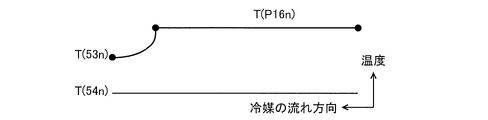
- FIG. FIG. 4 is a diagram showing detection values of each sensor when each sensor of the refrigerating and air-conditioning apparatus according to Embodiment 1 is normal;
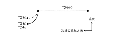
- 4 is a diagram showing detection values of each sensor when a condenser outlet temperature sensor of the refrigerating and air-conditioning apparatus according to Embodiment 1 is abnormal;
- FIG. 4 is a flow chart showing the flow of control in the sensor abnormality determination mode of the refrigerating and air-conditioning apparatus according to Embodiment 1; 7 is a flow chart showing the flow of control in the sensor abnormality determination mode according to the modified example of the refrigerating and air-conditioning apparatus according to Embodiment 1; FIG. 7 is a diagram showing the configuration of a refrigerating and air-conditioning apparatus according to Embodiment 2; FIG. 9 is a diagram showing detection values of each sensor when each sensor of the refrigerating and air-conditioning apparatus according to Embodiment 2 is normal; FIG.
- 10 is a diagram showing detection values of each sensor when an evaporator outlet temperature sensor of the refrigerating and air-conditioning apparatus according to Embodiment 2 is abnormal; 9 is a flow chart showing the flow of control in the sensor abnormality determination mode of the refrigerating and air-conditioning apparatus according to Embodiment 2; 10 is a flow chart showing the flow of control in a sensor abnormality determination mode according to a modified example of the refrigerating and air-conditioning apparatus according to Embodiment 2;
- FIG. 1 is a diagram showing the configuration of a refrigerating and air-conditioning apparatus 100 according to Embodiment 1.
- a refrigerating and air-conditioning apparatus 100 as shown in FIG. 1, one indoor unit 20 is provided with a liquid pipe 41 and a gas pipe 42 (hereinafter referred to as refrigerant pipes) for one outdoor unit 10. , and illustrates an air conditioner that performs cooling operation.
- FIG. 1 shows a configuration in which the refrigerating and air-conditioning apparatus 100 includes one indoor unit 20, a configuration including a plurality of indoor units 20 may be used. machines 20 are connected in parallel by refrigerant pipes.
- the outdoor unit 10 includes a compressor 11, a condenser 12, a high pressure sensor 16, a condenser outlet temperature sensor 53, and a condenser ambient temperature sensor 54.
- the condenser outlet temperature sensor 53 is also referred to as the first temperature sensor
- the condenser ambient temperature sensor 54 is also referred to as the second temperature sensor
- the high pressure sensor 16 is also referred to as the third sensor.
- the indoor unit 20 includes an expansion device 21 and an evaporator 22.
- a refrigerating and air-conditioning apparatus 100 includes a refrigerant circuit 1 in which a compressor 11, a condenser 12, an expansion device 21, and an evaporator 22 are sequentially connected in a circular manner by refrigerant pipes, and refrigerant circulates.
- the refrigerant circuit 1 contains an azeotropic refrigerant.
- the refrigerant circuit 1 may be configured to be connected to a channel switching device such as a four-way valve, and such a configuration enables heating operation in addition to cooling operation.
- the refrigerating and air-conditioning apparatus 100 also includes a control device 30, a notification unit 36, and an operation mode switching unit 37.
- the control device 30 is connected to the notification unit 36 and the operation mode switching unit 37, respectively.
- the notification unit 36 and the operation mode switching unit 37 may be provided in the control device 30 as part of the control device 30 .
- the compressor 11 is a fluid machine that draws in low-temperature, low-pressure gas refrigerant, compresses it, and discharges it as high-temperature, high-pressure gas refrigerant. When the compressor 11 operates, the refrigerant circulates through the refrigerant circuit 1 .
- the compressor 11 is, for example, an inverter-driven type whose operating frequency can be adjusted. Also, the operation of the compressor 11 is controlled by the control device 30 .
- the condenser 12 performs heat exchange between the refrigerant and the outdoor air.
- a fan (not shown) may be provided in the vicinity of the condenser 12. In this case, the rotation speed of the fan is changed to change the air volume, thereby changing the amount of heat released to the outdoor air, that is, the amount of heat exchange. be able to.
- the expansion device 21 adiabatically expands the refrigerant.
- the expansion device 21 is, for example, an electronic expansion valve or a thermal expansion valve.
- the degree of opening of the expansion device 21 is controlled by the control device 30 so that the degree of superheat at the outlet of the evaporator 22 approaches the target value.
- the evaporator 22 performs heat exchange between the refrigerant and the indoor air.
- a fan (not shown) may be provided in the vicinity of the evaporator 22. In this case, by changing the number of revolutions of the fan, the amount of air is changed, and the amount of heat absorbed from the indoor air, that is, the amount of heat exchange is changed. be able to.
- the high-pressure sensor 16 is provided on the discharge side of the compressor 11 to detect the pressure of the refrigerant on the discharge side of the compressor 11 and output a detection signal to the control device 30 .
- the high-pressure sensor 16 receives, for example, the pressure of a refrigerant with a diaphragm, detects it with a pressure-sensitive element via hydraulic pressure, converts it into an electrical signal corresponding to the pressure, and outputs it.
- the condensation temperature T(P16) is calculated from the pressure detected by the high-pressure sensor 16 .
- a condensation temperature sensor may be provided at an intermediate portion of the heat transfer tubes forming the condenser 12 to detect the temperature of the refrigerant flowing therethrough, that is, the condensation temperature T(P16). In the following, the condensation temperature is also referred to as saturation temperature.
- the condenser outlet temperature sensor 53 is provided between the condenser 12 and the expansion device 21, and detects the temperature T (53) of the refrigerant on the outlet side of the condenser 12 (hereinafter referred to as the condenser outlet temperature). and outputs a detection signal to the control device 30 .
- a condenser ambient temperature sensor 54 is provided in the vicinity of the condenser 12, detects a temperature T (54) around the condenser 12 (hereinafter referred to as condenser ambient temperature), and outputs a detection signal to the controller 30. output to The condenser outlet temperature sensor 53 and the condenser ambient temperature sensor 54 are, for example, thermistors whose resistance values change with temperature.
- the control device 30 is, for example, dedicated hardware, or a CPU (also referred to as a central processing unit, a central processing unit, a processing unit, an arithmetic unit, a microprocessor, or a processor) that executes a program stored in a storage unit 31, which will be described later. Configured.
- a CPU also referred to as a central processing unit, a central processing unit, a processing unit, an arithmetic unit, a microprocessor, or a processor
- control device 30 may be, for example, a single circuit, a composite circuit, an ASIC (Application Specific Integrated Circuit), an FPGA (Field-Programmable Gate Array), or a combination thereof. Applicable. Each functional unit implemented by the control device 30 may be implemented by separate hardware, or each functional unit may be implemented by one piece of hardware.
- ASIC Application Specific Integrated Circuit
- FPGA Field-Programmable Gate Array
- each function executed by the control device 30 is implemented by software, firmware, or a combination of software and firmware.
- Software and firmware are written as programs and stored in the storage unit 31 .
- the CPU implements each function of the control device 30 by reading and executing the programs stored in the storage unit 31 .
- control device 30 may be realized by dedicated hardware, and part of them may be realized by software or firmware.
- the control device 30 operates the compressor 11, the throttle device 21, etc., based on detection signals from various sensors provided in the refrigerating and air-conditioning apparatus 100 and operation signals from an operation unit (not shown) such as a remote controller. control and control the operation of the entire refrigerating and air-conditioning apparatus 100 .
- the control device 30 may be provided inside the outdoor unit 10 or the indoor unit 20 , or may be provided outside the outdoor unit 10 and the indoor unit 20 .
- the control device 30 includes a storage unit 31, an extraction unit 32, a calculation unit 33, a comparison unit 34, and a determination unit 35 as functional blocks related to sensor abnormality determination.
- the sensor abnormality determination is to determine whether or not the temperature sensor in the refrigerating and air-conditioning apparatus 100 is abnormal.
- the storage unit 31 stores various types of information, and includes, for example, rewritable non-volatile semiconductor memory such as flash memory, EPROM, and EEPROM. Note that the storage unit 31 may also include, for example, a non-volatile semiconductor memory in which data cannot be rewritten, such as a ROM, or a volatile semiconductor memory in which data can be rewritten, such as a RAM.
- the storage unit 31 stores, for example, temperature data and pressure data detected by each sensor. Note that these temperature data and pressure data are acquired periodically during operation of the refrigerating and air-conditioning apparatus 100 . In addition, the storage unit 31 stores each threshold, which will be described later.
- the extraction unit 32 extracts data necessary for sensor abnormality determination, such as detection values of each sensor, from the data stored in the storage unit 31 .
- data obtained when the compressor 11 is in operation is used for sensor abnormality determination. This is because when the compressor 11 is not in operation, it is not possible to correctly determine whether or not a sensor abnormality has occurred.
- the calculation unit 33 performs necessary calculations based on the data extracted by the extraction unit 32.
- the calculation unit 33 calculates the condensation temperature T(P16) from the pressure data detected by the high pressure sensor 16, for example.
- the comparison unit 34 compares the value obtained by the calculation in the calculation unit 33 with a preset threshold or the like, or compares the values obtained by the calculation in the calculation unit 33 with each other.
- the determination unit 35 determines, for example, whether or not the condenser outlet temperature sensor 53 is abnormal based on the comparison result of the comparison unit 34 .
- the notification unit 36 notifies various information such as the occurrence of an abnormality according to a command from the control device 30 .
- the notification unit 36 includes at least one of display means such as a display lamp or a monitor for visually notifying information, and audio output means such as a speaker for aurally notifying information.
- the operation mode switching unit 37 receives an operation mode switching operation by the user.
- the operation mode switching unit 37 can be provided, for example, in the operation unit described above.
- a signal is output from the operation mode switching unit 37 to the control device 30, and the control device 30 switches the operation mode based on the signal.
- the control device 30 has at least a normal operation mode and a sensor abnormality determination mode as operation modes.
- the high-temperature and high-pressure gas refrigerant discharged from the compressor 11 flows into the condenser 12 .
- the gas refrigerant that has flowed into the condenser 12 exchanges heat with the outdoor air there, condenses, becomes high-pressure liquid refrigerant, and flows out of the condenser 12 .
- the liquid refrigerant that has flowed out of the condenser 12 is depressurized by the expansion device 21 and flows into the evaporator 22 as a low-pressure two-layer refrigerant.
- the two-layer refrigerant that has flowed into the evaporator 22 exchanges heat with the indoor air, evaporates, and flows out of the evaporator 22 as a low-temperature, low-pressure gas refrigerant.
- the gas refrigerant that has flowed out of the evaporator 22 is sucked into the compressor 11, where it is discharged again as a high-temperature and high-pressure gas refrigerant.
- the condenser outlet temperature sensor 53 is in close contact with the piping on the outlet side of the condenser 12 (hereinafter referred to as outlet piping). Furthermore, the condenser outlet temperature sensor 53 is insulated with a heat insulating material together with the outlet side piping so as not to be affected by the ambient temperature of the condenser 12 .
- factors that cause an abnormality in the condenser outlet temperature sensor 53 include the deterioration of the heat insulating material due to deterioration over time, resulting in a decrease in heat insulating performance, the peeling of the heat insulating material, or the connection between the condenser outlet temperature sensor 53 and the outlet side piping. It is conceivable that the condenser 12 becomes susceptible to the ambient temperature due to the presence of a gap between them. When this abnormality occurs, the detection value of the condenser outlet temperature sensor 53 gradually decreases from the normal value, making it difficult to determine the abnormality.
- the ambient temperature of the condenser 12 slightly changes depending on the position. . Therefore, the degree of influence of the ambient temperature of the condenser 12 on the detection value of the condenser outlet temperature sensor 53 when the above abnormality occurs varies depending on the position of the condenser outlet temperature sensor 53 .
- FIG. 2 is a diagram showing detection values of each sensor when each sensor of the refrigerating and air-conditioning apparatus 100 according to Embodiment 1 is normal.
- FIG. 3 is a diagram showing detection values of each sensor when the condenser outlet temperature sensor 53 of the refrigerating and air-conditioning apparatus 100 according to Embodiment 1 is abnormal.
- T(54n), T(53n), and T(P16n) are as follows, as shown in FIG.
- T(54n) is the condenser ambient temperature detected by the condenser ambient temperature sensor 54 in normal conditions
- T(53n) is the condenser outlet temperature detected by the condenser outlet temperature sensor 53 in normal conditions.
- T(P16n) is the condensation temperature calculated from the pressure detected by the high-pressure sensor 16 during normal operation.
- the condenser 12 can be designed using an index of temperature efficiency ⁇ cond, and ⁇ cond can be expressed by the following equation (1).
- the condenser 12 is designed so that the temperature efficiency ⁇ cond is within a preset temperature efficiency threshold ⁇ c_th, for example, 0.7, when the detected values of the sensors are normal. This is because the heat exchange efficiency per unit heat exchange area is good because the temperature difference between the air heat-exchanging in the condenser 12 and the refrigerant can be large until the temperature efficiency ⁇ cond is about 0.7. However, when the temperature efficiency ⁇ cond is higher than 0.7, the temperature difference between the air and the refrigerant heat-exchanging in the condenser 12 becomes small, and the heat exchange efficiency per unit heat exchange area decreases. In order to obtain this, it is necessary to enlarge the condenser 12, which increases the cost. Therefore, in order to keep costs down, when designing the condenser 12, it is desirable to keep the temperature efficiency ⁇ cond within 0.7.
- ⁇ c_th for example, 0.7
- the temperature efficiency threshold ⁇ c_th is set and the temperature efficiency ⁇ cond is calculated in order to detect the abnormality of the condenser outlet temperature sensor 53 . If the temperature efficiency ⁇ cond is higher than the temperature efficiency threshold ⁇ c_th, it can be determined to be abnormal, and if the temperature efficiency ⁇ cond is equal to or less than the temperature efficiency threshold ⁇ c_th, it can be determined to be normal.
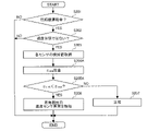
- FIG. 4 is a flow chart showing the control flow of the refrigerating and air-conditioning apparatus 100 according to Embodiment 1 in the sensor abnormality determination mode.
- the control device 30 switches from the normal operation mode to the sensor abnormality determination mode at predetermined time intervals, and performs the abnormality determination process described below.
- the control device 30 switches from the normal operation mode to the sensor abnormality determination mode, and performs the abnormality determination process described below.
- Step S101 Control device 30 determines whether compressor 11 is in operation. When the control device 30 determines that the compressor 11 is in operation (YES), the process proceeds to step S102. On the other hand, when the control device 30 determines that the compressor 11 is not in operation (NO), the sensor abnormality determination process ends. Thus, the reason why the sensor abnormality determination process ends when the compressor 11 is not in operation is that the sensor abnormality detection is correctly performed even if the sensor abnormality determination process is executed when the compressor 11 is not in operation. This is because it is not possible to
- Step S102 Control device 30 determines whether or not there is a transient state.
- the transient state is, for example, when the compressor 11 is started, or when the opening degree of the expansion device 21 fluctuates greatly and the amount of liquid refrigerant stored on the high pressure side fluctuates. It is in a state of not doing so.
- the control device 30 determines that the state is not in a transient state (YES)
- the process proceeds to step S103.
- the control device 30 determines that the state is in a transient state (NO)
- NO the sensor abnormality determination process ends. The reason why the sensor abnormality determination process is terminated in the transient state is that even if the sensor abnormality determination process is executed in the transient state, the sensor abnormality detection cannot be performed correctly.
- Step S103 Control device 30 acquires detection values from high pressure sensor 16, condenser outlet temperature sensor 53, and condenser ambient temperature sensor 54, respectively. Note that the process of step S103 is not limited to after step S102, and may be performed before step S101 or before step S102.
- Step S104A Controller 30 calculates temperature efficiency ⁇ cond based on the values detected by high pressure sensor 16 , condenser outlet temperature sensor 53 , and condenser ambient temperature sensor 54 . Note that the calculation of the temperature efficiency ⁇ cond is performed using the above equation (1). After that, the process proceeds to step S105A.
- Step S105A The control device 30 determines whether or not the temperature efficiency ⁇ cond is higher than a preset temperature efficiency threshold ⁇ c_th.
- a preset temperature efficiency threshold ⁇ c_th a preset temperature efficiency threshold
- the process proceeds to step S106.
- the control device 30 determines that the temperature efficiency ⁇ cond is not higher than the temperature efficiency threshold ⁇ c_th (NO)
- the process proceeds to step S107.
- Step S106 The controller 30 determines that the condenser outlet temperature sensor 53 is abnormal, and notifies that the condenser outlet temperature sensor 53 is abnormal by the notification unit 36 . After that, the sensor abnormality determination process ends.
- Step S107 Control device 30 determines that each sensor is normal, and terminates the sensor abnormality determination process.
- the condenser outlet temperature sensor 53 is an important sensor used for refrigerant leakage detection. Therefore, when the detection value of the condenser outlet temperature sensor 53 is abnormal, the control device 30 does not perform the refrigerant leakage detection process.
- the compressor 11 When the speed of the compressor 11 is increased when a sensor abnormality occurs, the refrigerant will be stored on the high pressure side and the high pressure will increase, which may cause the refrigerating and air-conditioning system 100 to malfunction.
- the sensor 53 detects an abnormality, the compressor frequency is not increased.
- the throttle device 21 is opened too much when the condenser outlet temperature sensor 53 becomes abnormal, the refrigerant may be sucked into the compressor 11 without being evaporated in the evaporator 22, and the refrigerating and air-conditioning apparatus 100 may break down.
- the control device 30 detects that the condenser outlet temperature sensor 53 has become abnormal, the control device 30 prevents the expansion device 21 from being excessively opened.
- the temperature efficiency ⁇ cond is used to perform the sensor abnormality determination process.
- Sensor abnormality determination processing is performed using the device outlet temperature threshold value Tcd_th.
- the condenser outlet temperature threshold Tcd_th can be calculated by the following formula (2).
- Tcd_th T(P16)- ⁇ c_th ⁇ (T(P16)-T(54)) (2) T (P16): condensation temperature [°C] T (54): Condenser ambient temperature [°C] ⁇ c_th: Temperature efficiency threshold [-]
- Equation (2) is obtained by inputting ⁇ c_th into ⁇ cond and Tcd_th into T(53) in equation (1).
- the temperature efficiency threshold ⁇ c_th is set and the condenser outlet temperature threshold Tcd_th is calculated in order to detect the abnormality of the condenser outlet temperature sensor 53 . If the detected value of the condenser outlet temperature sensor 53 is lower than the condenser outlet temperature threshold value Tcd_th, it is determined to be abnormal, and if the detected value of the condenser outlet temperature sensor 53 is equal to or higher than the condenser outlet temperature threshold value Tcd_th, it is determined to be normal. can be done.
- FIG. 5 is a flow chart showing the flow of control in the sensor abnormality determination mode according to the modified example of the refrigerating and air-conditioning apparatus 100 according to the first embodiment.
- steps S101 to S103 and S106 to S107 in FIG. 5 are the same processes as those already explained, so explanations thereof will be omitted.
- step S103 of FIG. 5 "the process proceeds to step S104A” in the above description of step S103 should be read as "the process proceeds to step S104B.”
- Step S104B The controller 30 calculates the condenser outlet temperature threshold Tcd_th.
- the calculation of the condenser outlet temperature threshold value Tcd_th is performed using the above equation (2). After that, the process proceeds to step S105B.
- Step S105B Controller 30 determines whether condenser outlet temperature T(53), which is a value detected by condenser outlet temperature sensor 53, is lower than condenser outlet temperature threshold Tcd_th.
- the controller 30 determines that the condenser outlet temperature T(53) is lower than the condenser outlet temperature threshold Tcd_th (YES)
- the process proceeds to step S106.
- the controller 30 determines that the condenser outlet temperature T(53) is not lower than the condenser outlet temperature threshold Tcd_th (NO)
- the process proceeds to step S107.
- the refrigerating and air-conditioning apparatus 100 includes the refrigerant circuit 1 in which the compressor 11, the condenser 12, the expansion device 21, and the evaporator 22 are connected by pipes, the refrigerant circulates, the condenser 12 and A first sensor sensing the outlet temperature of one of the evaporators 22, a second sensor sensing the ambient temperature of one of the condenser 12 and the evaporator 22, and flow through one of the condenser 12 and the evaporator 22.
- a third sensor that detects the saturation temperature of the refrigerant or detects the pressure for calculating the saturation temperature, and the temperature efficiency is calculated from the detection values of the first sensor, the second sensor, and the third sensor, or A control device 30 for calculating an outlet temperature threshold from the detection values of the second sensor and the third sensor and a preset temperature efficiency threshold. Then, the control device 30 determines that the first sensor is abnormal when the temperature efficiency is higher than the temperature efficiency threshold or based on the result of comparison between the detection value of the first sensor and the outlet temperature threshold.
- the condenser 12 or the evaporator 22 when the temperature efficiency is higher than the temperature efficiency threshold, or when the comparison result between the detection value of the first sensor and the outlet temperature threshold, the condenser 12 or the evaporator 22 It is determined that the first sensor that detects the outlet temperature of is abnormal. As described above, according to the refrigerating and air-conditioning apparatus 100 according to Embodiment 1, it is possible to identify that the first sensor, which is the temperature sensor, is abnormal.
- the first sensor detects the outlet temperature of the condenser 12
- the second sensor detects the ambient temperature of the condenser 12
- the third sensor detects the condensation It detects temperature. Then, when the detection value of the first sensor is lower than the outlet temperature threshold, the control device 30 determines that the first sensor is abnormal.
- the condenser outlet temperature sensor 53 which is the first sensor for detecting the outlet temperature of the condenser 12, is abnormal.
- control device 30 does not increase the compressor frequency when the first sensor is abnormal.
- the refrigerating and air-conditioning apparatus 100 According to the refrigerating and air-conditioning apparatus 100 according to Embodiment 1, it is possible to prevent the refrigerating and air-conditioning apparatus 100 from breaking down.
- Embodiment 2 will be described below, but descriptions of parts that overlap with those of Embodiment 1 will be omitted, and parts that are the same as or correspond to those of Embodiment 1 will be given the same reference numerals.
- FIG. 6 is a diagram showing the configuration of a refrigerating and air-conditioning apparatus 100 according to Embodiment 2. As shown in FIG. A refrigerating and air-conditioning apparatus 100 according to the second embodiment differs from that of the first embodiment in the provided sensors.
- the outdoor unit 10 includes a compressor 11, a condenser 12, and a low pressure sensor 18.
- the indoor unit 20 includes an expansion device 21, an evaporator 22, an evaporator outlet temperature sensor 63, and an evaporator ambient temperature sensor 64.
- the evaporator outlet temperature sensor 63 is also referred to as the first temperature sensor
- the evaporator ambient temperature sensor 64 is also referred to as the second temperature sensor
- the low pressure sensor 18 is also referred to as the third sensor.
- the low pressure sensor 18 is provided on the suction side of the compressor 11 to detect the pressure on the suction side of the compressor 11 and output a detection signal to the control device 30 .
- the low-pressure sensor 18 receives, for example, the pressure of a refrigerant with a diaphragm, detects it with a pressure-sensitive element via hydraulic pressure, converts it into an electric signal corresponding to the pressure, and outputs it. From the pressure detected by the low-pressure sensor 18, the evaporation temperature T(P18) is calculated.
- an evaporation temperature sensor may be provided in the intermediate portion of the heat transfer tube forming the evaporator 22 to detect the temperature of the refrigerant flowing therethrough, that is, the evaporation temperature T(P18). In the following, the evaporation temperature is also referred to as saturation temperature.
- the evaporator outlet temperature sensor 63 is provided between the evaporator 22 and the compressor 11, and detects the temperature T (63) of the refrigerant on the outlet side of the evaporator 22 (hereinafter referred to as the evaporator outlet temperature). and outputs a detection signal to the control device 30 .
- the evaporator ambient temperature sensor 64 is provided near the evaporator 22, detects the ambient temperature T (64) of the evaporator 22 (hereinafter referred to as the evaporator ambient temperature), and outputs a detection signal to the controller 30. output to The evaporator outlet temperature sensor 63 and the evaporator ambient temperature sensor 64 are, for example, thermistors whose resistance values change with temperature.
- the evaporator outlet temperature sensor 63 is in close contact with the pipe on the outlet side of the evaporator 22 (hereinafter referred to as outlet pipe) in order to accurately detect the temperature of the refrigerant on the outlet side of the evaporator 22 . Furthermore, the evaporator outlet temperature sensor 63 is insulated with a heat insulating material together with the outlet side pipe so as not to be affected by the ambient temperature of the evaporator 22 .
- the factors that cause an abnormality in the evaporator outlet temperature sensor 63 include deterioration of the heat insulating material due to deterioration over time, deteriorating the heat insulating performance, peeling off of the heat insulating material, or the connection between the evaporator outlet temperature sensor 63 and the outlet side piping. It is conceivable that the ambient temperature of the evaporator 22 may easily affect the evaporator 22 due to the presence of a gap between them. When this abnormality occurs, the detection value of the evaporator outlet temperature sensor 63 gradually rises from the normal value, making it difficult to determine the abnormality.
- the temperature of the air on the outlet side of the evaporator 22 is lower than the air on the inlet side of the evaporator 22 by the amount of heat exchanged by the evaporator 22, so the ambient temperature of the evaporator 22 changes somewhat depending on the position. . Therefore, the degree of influence of the ambient temperature of the evaporator 22 on the detection value of the evaporator outlet temperature sensor 63 when the above abnormality occurs varies depending on the position of the evaporator outlet temperature sensor 63 .
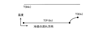
- FIG. 7 is a diagram showing detection values of each sensor when each sensor of the refrigerating and air-conditioning apparatus 100 according to Embodiment 2 is normal.
- FIG. 8 is a diagram showing detection values of each sensor when the evaporator outlet temperature sensor 63 of the refrigerating and air-conditioning apparatus 100 according to Embodiment 2 is abnormal.
- T(64n), T(63n), and T(P18n) are as follows, as shown in FIG.
- T(64n) is the evaporator ambient temperature detected by the evaporator ambient temperature sensor 64 under normal conditions
- T(63n) is the evaporator outlet temperature detected by the evaporator outlet temperature sensor 63 under normal conditions.
- T(P18n) is the evaporation temperature calculated from the pressure detected by the low-pressure sensor 18 during normal operation.
- T(63a) is the evaporator outlet temperature detected by the evaporator outlet temperature sensor 63 at the time of abnormality.
- the evaporator 22 can be designed using an index of temperature efficiency ⁇ eva, which can be expressed by the following formula (3).
- the evaporator 22 is designed so that the temperature efficiency ⁇ eva is within a preset temperature efficiency threshold ⁇ e_th, for example, 0.5, when the detection value of each sensor is normal. This is because if the exit state of the evaporator 22 is excessively superheated and gasified, the heat exchange efficiency is lowered, and since the evaporator 22 is mounted on the indoor unit 20, it is desirable that the size of the evaporator 22 is as small as possible. Therefore, in order to achieve both miniaturization and high performance of the evaporator 22, it is desirable to keep the temperature efficiency ⁇ eva within 0.5.
- ⁇ e_th for example, 0.5
- the temperature efficiency threshold ⁇ e_th is set to detect an abnormality in the evaporator outlet temperature sensor 63, and the temperature efficiency ⁇ eva is calculated. Then, if the temperature efficiency ⁇ eva is higher than the temperature efficiency threshold ⁇ e_th, it can be determined to be abnormal, and if the temperature efficiency ⁇ eva is equal to or less than the temperature efficiency threshold ⁇ e_th, it can be determined to be normal.
- FIG. 9 is a flow chart showing the flow of control in the sensor abnormality determination mode of the refrigerating and air-conditioning apparatus 100 according to the second embodiment.
- the control device 30 switches from the normal operation mode to the sensor abnormality determination mode at predetermined time intervals, and performs the abnormality determination process described below.
- the control device 30 switches from the normal operation mode to the sensor abnormality determination mode, and performs the abnormality determination process described below.
- Step S201 Control device 30 determines whether compressor 11 is in operation. When the control device 30 determines that the compressor 11 is in operation (YES), the process proceeds to step S202. On the other hand, when the control device 30 determines that the compressor 11 is not in operation (NO), the sensor abnormality determination process ends. Thus, the reason why the sensor abnormality determination process ends when the compressor 11 is not in operation is that the sensor abnormality detection is correctly performed even if the sensor abnormality determination process is executed when the compressor 11 is not in operation. This is because it is not possible to
- Step S202 Control device 30 determines whether or not there is a transient state.
- the transient state is, for example, when the compressor 11 is started, or when the opening degree of the expansion device 21 fluctuates greatly and the amount of liquid refrigerant stored on the high pressure side fluctuates. It is in a state of not doing so.
- the control device 30 determines that it is not in a transient state (YES)
- the process proceeds to step S203.
- the control device 30 determines that the state is in a transient state (NO)
- NO the sensor abnormality determination process ends. The reason why the sensor abnormality determination process is terminated in the transient state is that even if the sensor abnormality determination process is executed in the transient state, the sensor abnormality detection cannot be performed correctly.
- Step S203 Control device 30 acquires detection values from low pressure sensor 18, evaporator outlet temperature sensor 63, and evaporator ambient temperature sensor 64, respectively. Note that the process of step S203 is not limited to after step S202, and may be performed before step S201 or before step S202.
- Step S204A The control device 30 calculates the temperature efficiency ⁇ eva based on the detection values of the low pressure sensor 18 , the evaporator outlet temperature sensor 63 and the evaporator ambient temperature sensor 64 . Note that the calculation of the temperature efficiency ⁇ eva is performed using the above equation (3). After that, the process proceeds to step S205A.
- Step S205A The control device 30 determines whether the temperature efficiency ⁇ eva is higher than a preset temperature efficiency threshold ⁇ e_th. When the control device 30 determines that the temperature efficiency ⁇ eva is higher than the temperature efficiency threshold ⁇ e_th (YES), the process proceeds to step S206. On the other hand, when the control device 30 determines that the temperature efficiency ⁇ eva is not higher than the temperature efficiency threshold ⁇ e_th (NO), the process proceeds to step S207.
- Step S206 The control device 30 determines that the evaporator outlet temperature sensor 63 is abnormal, and notifies that the evaporator outlet temperature sensor 63 is abnormal by the notification unit 36 . After that, the sensor abnormality determination process ends.
- Step S207 Control device 30 determines that each sensor is normal, and terminates the sensor abnormality determination process.
- the evaporator outlet temperature sensor 63 is an important sensor used for detecting an abnormality in the expansion device 21 and a heat transfer failure in the evaporator 22. Therefore, when the detected value of the evaporator outlet temperature sensor 63 is abnormal, the control device 30 does not perform the processing of detecting the abnormality of the expansion device 21 and the poor heat transfer of the evaporator 22 .
- the compressor 11 When the speed of the compressor 11 is increased when a sensor abnormality occurs, the refrigerant will be stored on the high pressure side and the high pressure will increase, which may cause the refrigerating and air-conditioning system 100 to malfunction.
- the sensor 63 detects an abnormality, the compressor frequency is not increased.
- the expansion device 21 is opened too much when an abnormality occurs in the evaporator outlet temperature sensor 63, the refrigerant may be sucked into the compressor 11 without being evaporated in the evaporator 22, and the refrigerating and air-conditioning apparatus 100 may malfunction.
- the control device 30 detects that the evaporator outlet temperature sensor 63 has become abnormal, the control device 30 prevents the expansion device 21 from being excessively opened.
- the sensor abnormality determination process is performed using the temperature efficiency ⁇ eva.
- Sensor abnormality determination processing is performed using the device outlet temperature threshold Ted_th.
- the evaporator outlet temperature threshold Ted_th can be calculated by the following formula.
- the temperature efficiency threshold ⁇ e_th is set and the evaporator outlet temperature threshold Ted_th is calculated in order to detect an abnormality in the evaporator outlet temperature sensor 63 . If the detected value of the evaporator outlet temperature sensor 63 is higher than the evaporator outlet temperature threshold Ted_th, it is determined to be abnormal, and if the detected value of the evaporator outlet temperature sensor 63 is equal to or lower than the evaporator outlet temperature threshold Ted_th, it is determined to be normal. can be done.
- FIG. 10 is a flow chart showing the flow of control in the sensor abnormality determination mode according to the modified example of the refrigerating and air-conditioning apparatus 100 according to the second embodiment.
- steps S201 to S203 and S206 to S207 in FIG. 9 are the same processes as those already explained, so explanations thereof will be omitted.
- step S203 of FIG. 10 "the process proceeds to step S204A” in the above description of step S203 should be read as "the process proceeds to step S204B.”
- Step S204B The control device 30 calculates the evaporator outlet temperature threshold Ted_th.
- the calculation of the evaporator outlet temperature threshold Ted_th is performed using the above equation (4). After that, the process proceeds to step S205B.
- Step S205B The controller 30 determines whether the evaporator outlet temperature T(63), which is the value detected by the evaporator outlet temperature sensor 63, is higher than the evaporator outlet temperature threshold Ted_th.
- the control device 30 determines that the evaporator outlet temperature T(63) is higher than the evaporator outlet temperature threshold Ted_th (YES)
- the process proceeds to step S206.
- the controller 30 determines that the evaporator outlet temperature T(63) is not higher than the evaporator outlet temperature threshold Ted_th (NO)
- the process proceeds to step S207.
- the sensor abnormality determination process is performed using the evaporator outlet temperature threshold Ted_th. Therefore, when the refrigerating and air-conditioning apparatus 100 is a multi-type in which a plurality of indoor units 20 having a common temperature efficiency threshold ⁇ e_th are connected in parallel, the evaporator calculated from the temperature efficiency threshold ⁇ e_th, the evaporation temperature, and the ambient temperature If the outlet temperature threshold Ted_th is calculated once, the calculated evaporator outlet temperature threshold Ted_th can be used for determination of all the indoor units 20, so the amount of calculation can be reduced.
- the first sensor detects the outlet temperature of the evaporator 22
- the second sensor detects the ambient temperature of the evaporator 22
- the third sensor detects the evaporation temperature. It detects temperature. Then, when the detection value of the first sensor is lower than the outlet temperature threshold, the control device 30 determines that the first sensor is abnormal.
- an abnormality in the evaporator outlet temperature sensor 63 which is the first sensor that detects the outlet temperature of the evaporator 22, can be identified.
- 1 refrigerant circuit 10 outdoor unit, 11 compressor, 12 condenser, 16 high pressure sensor, 18 low pressure sensor, 20 indoor unit, 21 expansion device, 22 evaporator, 30 control device, 31 storage unit, 32 extraction unit, 33 Computing section, 34 Comparing section, 35 Judging section, 36 Reporting section, 37 Operation mode switching section, 41 Liquid pipe, 42 Gas pipe, 53 Condenser outlet temperature sensor, 54 Condenser ambient temperature sensor, 63 Evaporator outlet temperature sensor , 64 evaporator ambient temperature sensor, 100 refrigeration air conditioner.
Landscapes
- Engineering & Computer Science (AREA)
- Physics & Mathematics (AREA)
- Mechanical Engineering (AREA)
- Thermal Sciences (AREA)
- General Engineering & Computer Science (AREA)
- Air Conditioning Control Device (AREA)
Abstract
冷凍空調装置は、圧縮機、凝縮器、絞り装置、および、蒸発器が配管で接続され、冷媒が循環する冷媒回路と、凝縮器および蒸発器のうち一方の出口温度を検知する第一センサと、凝縮器および蒸発器のうち一方の周囲温度を検知する第二センサと、凝縮器および蒸発器のうち一方を流れる冷媒の飽和温度を検知、または飽和温度を算出するための圧力を検知する第三センサと、第一センサ、第二センサ、および、第三センサの検知値から温度効率を算出する、あるいは、第二センサおよび第三センサの検知値、並びに、あらかじめ設定された温度効率閾値から出口温度閾値を算出する制御装置と、を備え、制御装置は、温度効率が温度効率閾値よりも高い場合、あるいは、第一センサの検知値と出口温度閾値との比較結果により、第一センサが異常であると判定するものである。
Description
本開示は、温度センサを備えた冷凍空調装置に関するものである。
従来、空気調和装置などの冷凍空調装置に設けられた圧力センサおよび温度センサの異常検知を行う技術がある(例えば、特許文献1参照)。
特許文献1は、蒸発器に設置した温度センサが検知する冷媒温度に基づいて冷媒の蒸発圧力を求め、この蒸発圧力と圧力センサが検知する冷媒圧力とを比較し、その演算値が所定範囲を外れるとき、圧力センサおよび温度センサのうち少なくとも一方が異常であると判定する。
しかしながら、特許文献1は、圧力センサおよび温度センサのうち少なくとも一方が異常であると判定することができるが、どちらのセンサが異常であるかは判定できない。そのため、温度センサが異常であったとしてもその特定ができないという課題があった。
本開示は、以上のような課題を解決するためになされたもので、温度センサに異常が発生していることを特定することができる冷凍空調装置を提供することを目的としている。
本開示に係る冷凍空調装置は、圧縮機、凝縮器、絞り装置、および、蒸発器が配管で接続され、冷媒が循環する冷媒回路と、前記凝縮器および前記蒸発器のうち一方の出口温度を検知する第一センサと、前記凝縮器および前記蒸発器のうち前記一方の周囲温度を検知する第二センサと、前記凝縮器および前記蒸発器のうち前記一方を流れる前記冷媒の飽和温度を検知、または前記飽和温度を算出するための圧力を検知する第三センサと、前記第一センサ、前記第二センサ、および、前記第三センサの検知値から温度効率を算出する、あるいは、前記第二センサおよび前記第三センサの検知値、並びに、あらかじめ設定された温度効率閾値から出口温度閾値を算出する制御装置と、を備え、前記制御装置は、前記温度効率が前記温度効率閾値よりも高い場合、あるいは、前記第一センサの検知値と前記出口温度閾値との比較結果により、前記第一センサが異常であると判定するものである。
本開示に係る冷凍空調装置によれば、温度効率が温度効率閾値よりも高い場合、あるいは、第一センサの検知値と出口温度閾値との比較結果により、凝縮器または蒸発器の出口温度を検知する第一センサが異常であると判定する。このように、本開示に係る冷凍空調装置によれば、温度センサである第一センサに異常が発生していることを特定することができる。
以下、本開示の実施の形態を図面に基づいて説明する。なお、以下に説明する実施の形態によって本開示が限定されるものではない。また、以下の図面では各構成部材の大きさの関係が実際のものとは異なる場合がある。
実施の形態1.
図1は、実施の形態1に係る冷凍空調装置100の構成を示す図である。
実施の形態1では、冷凍空調装置100として、図1に示すように、1台の室外機10に対して1台の室内機20が液管41およびガス管42(以下、冷媒配管と称する)で接続され、冷房運転を行う空気調和装置を例示している。なお、図1では冷凍空調装置100が1台の室内機20を備えた構成を示しているが、複数の室内機20を備えた構成でもよく、その場合は、室外機10に対して各室内機20が冷媒配管で並列に接続される。
図1は、実施の形態1に係る冷凍空調装置100の構成を示す図である。
実施の形態1では、冷凍空調装置100として、図1に示すように、1台の室外機10に対して1台の室内機20が液管41およびガス管42(以下、冷媒配管と称する)で接続され、冷房運転を行う空気調和装置を例示している。なお、図1では冷凍空調装置100が1台の室内機20を備えた構成を示しているが、複数の室内機20を備えた構成でもよく、その場合は、室外機10に対して各室内機20が冷媒配管で並列に接続される。
室外機10は、圧縮機11と、凝縮器12と、高圧圧力センサ16と、凝縮器出口温度センサ53と、凝縮器周囲温度センサ54とを備えている。なお、以下において、凝縮器出口温度センサ53は第一温度センサとも称し、凝縮器周囲温度センサ54は第二温度センサとも称し、高圧圧力センサ16は第三センサとも称する。
室内機20は、絞り装置21と、蒸発器22とを備えている。
冷凍空調装置100は、圧縮機11、凝縮器12、絞り装置21、および、蒸発器22が冷媒配管で環状に順次接続され、冷媒が循環する冷媒回路1を備えている。冷媒回路1には、共沸冷媒が封入されている。なお、冷媒回路1には、四方弁などの流路切替装置が接続されている構成でもよく、そのような構成にすることで、冷房運転に加えて暖房運転を行うことが可能となる。
また、冷凍空調装置100は、制御装置30と、報知部36と、運転モード切替部37とを備えており、制御装置30には、報知部36および運転モード切替部37がそれぞれ接続されている。なお、報知部36および運転モード切替部37は、制御装置30の一部として制御装置30に備えられていてもよい。
圧縮機11は、低温低圧のガス冷媒を吸入して圧縮し、高温高圧のガス冷媒として吐出する流体機械である。圧縮機11が動作すると、冷媒回路1内を冷媒が循環する。圧縮機11は、例えば運転周波数の調整が可能なインバータ駆動式である。また、圧縮機11の動作は、制御装置30によって制御される。
凝縮器12は、冷媒と室外空気との熱交換を行うものである。なお、凝縮器12の近傍にファン(図示せず)を設けてもよく、その場合はファンの回転数を変化させることにより風量を変化させ、室外空気への放熱量つまり熱交換量を変化させることができる。
絞り装置21は、冷媒を断熱膨張させるものである。絞り装置21は、例えば電子式膨張弁あるいは温度式膨張弁などである。絞り装置21の開度は、蒸発器22の出口の過熱度が目標値に近づくように、制御装置30によって制御される。
蒸発器22は、冷媒と室内空気との熱交換を行うものである。なお、蒸発器22の近傍にファン(図示せず)を設けてもよく、その場合はファンの回転数を変化させることにより風量を変化させ、室内空気からの吸熱量つまり熱交換量を変化させることができる。
高圧圧力センサ16は、圧縮機11の吐出側に設けられており、圧縮機11の吐出側の冷媒の圧力を検知し、検知信号を制御装置30に出力する。高圧圧力センサ16は、例えば冷媒の圧力をダイヤフラムで受け、油圧を介して感圧素子で検知し、圧力に応じた電気信号に変換して出力するものである。この高圧圧力センサ16が検知した圧力の検知値から、凝縮温度T(P16)が算出される。なお、高圧圧力センサ16の代わりに凝縮器12を構成する伝熱管の中間部分に設けられ、そこを流れる冷媒の温度、つまり凝縮温度T(P16)を検知する凝縮温度センサを設けてもよい。また、以下において、凝縮温度は飽和温度とも称する。
凝縮器出口温度センサ53は、凝縮器12と絞り装置21との間に設けられており、凝縮器12の出口側の冷媒の温度T(53)(以下、凝縮器出口温度と称する)を検知し、検知信号を制御装置30に出力する。凝縮器周囲温度センサ54は、凝縮器12の近傍に設けられており、凝縮器12の周囲の温度T(54)(以下、凝縮器周囲温度と称する)を検知し、検知信号を制御装置30に出力する。凝縮器出口温度センサ53および凝縮器周囲温度センサ54は、例えば温度により抵抗値が変化するサーミスタである。
制御装置30は、例えば、専用のハードウェア、または後述する記憶部31に格納されるプログラムを実行するCPU(Central Processing Unit、中央処理装置、処理装置、演算装置、マイクロプロセッサ、プロセッサともいう)で構成される。
制御装置30が専用のハードウェアである場合、制御装置30は、例えば、単一回路、複合回路、ASIC(Application Specific Integrated Circuit)、FPGA(Field-Programmable Gate Array)、またはこれらを組み合わせたものが該当する。制御装置30が実現する各機能部のそれぞれを、個別のハードウェアで実現してもよいし、各機能部を一つのハードウェアで実現してもよい。
制御装置30がCPUの場合、制御装置30が実行する各機能は、ソフトウェア、ファームウェア、またはソフトウェアとファームウェアとの組み合わせにより実現される。ソフトウェアおよびファームウェアはプログラムとして記述され、記憶部31に格納される。CPUは、記憶部31に格納されたプログラムを読み出して実行することにより、制御装置30の各機能を実現する。
なお、制御装置30の機能の一部を専用のハードウェアで実現し、一部をソフトウェアまたはファームウェアで実現するようにしてもよい。
制御装置30は、冷凍空調装置100に設けられた各種センサからの検知信号、および、リモコンなどの操作部(図示せず)からの操作信号などに基づいて、圧縮機11および絞り装置21などを制御し、冷凍空調装置100全体の動作を制御する。なお、制御装置30は、室外機10あるいは室内機20の内部に設けられていてもよいし、室外機10および室内機20の外部に設けられていてもよい。
制御装置30は、センサ異常判定に関わる機能ブロックとして、記憶部31と、抽出部32と、演算部33と、比較部34と、判定部35とを備えている。ここで、センサ異常判定とは、冷凍空調装置100において、温度センサに異常が発生しているかどうかを判定することである。
記憶部31は、各種情報を記憶するものであり、例えば、フラッシュメモリ、EPROM、および、EEPROMなどの、データの書き換え可能な不揮発性の半導体メモリを備えている。なお、記憶部31は、その他に、例えばROMなどのデータの書き換え不可能な不揮発性の半導体メモリ、あるいは、RAMなどのデータの書き換え可能な揮発性の半導体メモリなどを備えていてもよい。記憶部31は、例えば各センサのそれぞれで検知された温度データおよび圧力データを記憶する。なお、これら温度データおよび圧力データは、冷凍空調装置100の運転中に定期的に取得される。また、記憶部31は、後述する各閾値を記憶する。
抽出部32は、記憶部31に記憶されたデータの中から、各センサの検知値などセンサ異常判定に必要となるデータを抽出するものである。ここで、センサ異常判定には、圧縮機11が運転しているときのデータが用いられる。これは、圧縮機11が運転していないときには、センサ異常が発生しているかどうかの判定を正しく行うことができないためである。
演算部33は、抽出部32で抽出されたデータに基づき、必要な演算を行うものである。この演算部33は、例えば、高圧圧力センサ16が検知した圧力データから、凝縮温度T(P16)を算出する。
比較部34は、演算部33での演算により得られた値とあらかじめ設定された閾値などとの比較、あるいは演算部33での演算により得られた値同士の比較を行うものである。
判定部35は、比較部34での比較結果に基づき、例えば凝縮器出口温度センサ53に異常が発生しているかどうかの判定などを行うものである。
報知部36は、制御装置30からの指令により、異常発生などの各種情報を報知するものである。報知部36は、表示灯あるいはモニターなどの情報を視覚的に報知する表示手段、および、スピーカーなどの情報を聴覚的に報知する音声出力手段のうち、少なくとも一方を備えている。
運転モード切替部37は、ユーザーによる運転モードの切替操作を受け付けるものである。運転モード切替部37は、例えば上記の操作部に設けることができる。運転モード切替部37で運転モードの切替操作が行われると、運転モード切替部37から制御装置30に対して信号が出力され、制御装置30は、その信号に基づいて運転モードを切り替える。制御装置30は、運転モードとして、少なくとも通常運転モードとセンサ異常判定モードとを有している。
次に、実施の形態1に係る冷凍空調装置100の通常運転モード時の運転動作について説明する。
圧縮機11から吐出した高温高圧のガス冷媒は、凝縮器12に流入する。凝縮器12に流入したガス冷媒は、そこで室外空気と熱交換し、凝縮して高圧の液冷媒となって凝縮器12から流出する。凝縮器12から流出した液冷媒は、絞り装置21によって減圧され、低圧の二層冷媒となって蒸発器22に流入する。そして、蒸発器22に流入した二層冷媒は、そこで室内空気と熱交換し、蒸発して低温低圧のガス冷媒となって蒸発器22から流出する。蒸発器22から流出したガス冷媒は、圧縮機11に吸入され、そこで再び高温高圧のガス冷媒となって吐出される。
次に、凝縮器出口温度センサ53の異常発生要因について説明する。
凝縮器出口温度センサ53は、凝縮器12の出口側の冷媒の温度を正確に検知するため、凝縮器12の出口側の配管(以下、出口側配管と称する)に密接している。さらに、凝縮器出口温度センサ53は、凝縮器12の周囲温度の影響を受けないように、出口側配管とともに断熱材によって断熱されている。そのため、凝縮器出口温度センサ53の異常発生要因としては、経年劣化により断熱材が劣化して断熱性能が低下したり、断熱材が剥がれ落ちたり、あるいは凝縮器出口温度センサ53と出口側配管との間に隙間が生じたりすることで、凝縮器12の周囲温度の影響を受けやすくなることが考えられる。この異常が発生すると、凝縮器出口温度センサ53の検知値が正常値から徐々に低下するため、異常判定しにくい。
なお、凝縮器12の入口側の空気に比べて凝縮器12の出口側の空気は、凝縮器12で熱交換した分だけ温度が高くなるため、凝縮器12の周囲温度は位置により多少変化する。このため、上記の異常が発生したときの、凝縮器出口温度センサ53の検知値への凝縮器12の周囲温度の影響の度合いは、凝縮器出口温度センサ53の位置により異なる。
次に、実施の形態1に係る冷凍空調装置100の凝縮器出口温度センサ53の異常検知方法について説明する。
図2は、実施の形態1に係る冷凍空調装置100の各センサが正常時の各センサの検知値を示す図である。図3は、実施の形態1に係る冷凍空調装置100の凝縮器出口温度センサ53が異常時の各センサの検知値を示す図である。
各センサの検知値が正常である場合、図2に示すように、T(54n)、T(53n)、T(P16n)の関係は、下記となる。ここで、T(54n)は、正常時の凝縮器周囲温度センサ54が検知した凝縮器周囲温度であり、T(53n)は、正常時の凝縮器出口温度センサ53が検知した凝縮器出口温度である。また、T(P16n)は、正常時の高圧圧力センサ16が検知した圧力から算出した凝縮温度である。
T(54n)≦T(53n)≦T(P16n)
次に、凝縮器出口温度センサ53が異常である場合、図3に示すように、T(53a)とT(53n)との関係は、下記となる。ここで、T(53a)は、異常時の凝縮器出口温度センサ53が検知した凝縮器出口温度である。
T(53a)<T(53n)
これは、凝縮器出口温度センサ53に上述のような異常が発生すると、凝縮器出口温度センサ53の検知値が、凝縮器周囲温度の影響を受け、凝縮器周囲温度センサ54の検知値に近づくように、正常値から徐々に低下するためである。
ここで、凝縮器12は、温度効率ηcondという指標を用いて設計することができ、ηcondは、下記の式(1)で表すことができる。
ηcond=(T(P16)-T(53))/(T(P16)-T(54))
・・・(1)
T(P16):凝縮温度[℃]
T(53):凝縮器出口温度[℃]
T(54):凝縮器周囲温度[℃]
・・・(1)
T(P16):凝縮温度[℃]
T(53):凝縮器出口温度[℃]
T(54):凝縮器周囲温度[℃]
なお、各センサの検知値が正常である場合、温度効率ηcondがあらかじめ設定された温度効率閾値ηc_th、例えば0.7以内になるように、凝縮器12は設計される。なぜならば、温度効率ηcondが0.7くらいまでは凝縮器12で熱交換される空気と冷媒との温度差を大きく取ることができるため単位熱交換面積当たりの熱交換効率はよい。しかし、温度効率ηcondが0.7より高くなると凝縮器12で熱交換される空気と冷媒との温度差が小さくなり単位熱交換面積当たりの熱交換効率が低下するので、所望の熱交換能力を得るためには凝縮器12を拡大する必要があり、コストが増加する。そのため、コストを抑えるためには、凝縮器12を設計する際に、温度効率ηcondを0.7以内にすることが望ましい。
そして、凝縮器出口温度センサ53が異常である場合、図3に示すように、T(53a)はT(54n)に近づき、その結果、温度効率ηcondは温度効率閾値ηc_thより高くなる。
以上より、実施の形態1において、凝縮器出口温度センサ53の異常検知を行うために温度効率閾値ηc_thを設定し、温度効率ηcondを算出する。そして、温度効率ηcondが温度効率閾値ηc_thよりも高い場合は異常、温度効率ηcondが温度効率閾値ηc_th以下であれば正常と判定することができる。
次に、実施の形態1に係る冷凍空調装置100のセンサ異常判定処理時の制御の流れについて説明する。
図4は、実施の形態1に係る冷凍空調装置100のセンサ異常判定モード時の制御の流れを示すフローチャートである。
制御装置30は、所定の時間間隔毎に通常運転モードからセンサ異常判定モードに切り替え、以下に説明する異常判定の処理を行う。または、制御装置30は、運転モード切替部37からユーザーによる異常検知モードへの切替操作を受け付けたら、通常運転モードからセンサ異常判定モードに切り替え、以下に説明する異常判定の処理を行う。
制御装置30は、所定の時間間隔毎に通常運転モードからセンサ異常判定モードに切り替え、以下に説明する異常判定の処理を行う。または、制御装置30は、運転モード切替部37からユーザーによる異常検知モードへの切替操作を受け付けたら、通常運転モードからセンサ異常判定モードに切り替え、以下に説明する異常判定の処理を行う。
(ステップS101)
制御装置30は、圧縮機11が運転中であるかどうかを判定する。制御装置30が、圧縮機11が運転中であると判定した場合(YES)、処理はステップS102に進む。一方、制御装置30が、圧縮機11が運転中ではないと判定した場合(NO)、センサ異常判定処理は終了する。このように、圧縮機11が運転中ではない場合にセンサ異常判定処理が終了するのは、圧縮機11の運転中以外にセンサ異常判定処理を実行しても、センサの異常検知を正しく行うことができないためである。
制御装置30は、圧縮機11が運転中であるかどうかを判定する。制御装置30が、圧縮機11が運転中であると判定した場合(YES)、処理はステップS102に進む。一方、制御装置30が、圧縮機11が運転中ではないと判定した場合(NO)、センサ異常判定処理は終了する。このように、圧縮機11が運転中ではない場合にセンサ異常判定処理が終了するのは、圧縮機11の運転中以外にセンサ異常判定処理を実行しても、センサの異常検知を正しく行うことができないためである。
(ステップS102)
制御装置30は、過渡状態でないかどうかを判定する。ここで、過渡状態とは、例えば圧縮機11の起動時、または、絞り装置21の開度が大きく変動して高圧側に貯留されている液冷媒量が変動する場合、などの運転動作が安定していない状態である。制御装置30が、過渡状態ではないと判定した場合(YES)、処理はステップS103に進む。一方、制御装置30が、過渡状態であると判定した場合(NO)、センサ異常判定処理は終了する。このように、過渡状態である場合にセンサ異常判定処理が終了するのは、過渡状態のときにセンサ異常判定処理を実行しても、センサの異常検知を正しく行うことができないためである。
制御装置30は、過渡状態でないかどうかを判定する。ここで、過渡状態とは、例えば圧縮機11の起動時、または、絞り装置21の開度が大きく変動して高圧側に貯留されている液冷媒量が変動する場合、などの運転動作が安定していない状態である。制御装置30が、過渡状態ではないと判定した場合(YES)、処理はステップS103に進む。一方、制御装置30が、過渡状態であると判定した場合(NO)、センサ異常判定処理は終了する。このように、過渡状態である場合にセンサ異常判定処理が終了するのは、過渡状態のときにセンサ異常判定処理を実行しても、センサの異常検知を正しく行うことができないためである。
(ステップS103)
制御装置30は、高圧圧力センサ16、凝縮器出口温度センサ53、および、凝縮器周囲温度センサ54から検知値をそれぞれ取得する。なお、ステップS103の処理は、ステップS102の後に限定されず、ステップS101の前あるいはステップS102の前に行ってもよい。
制御装置30は、高圧圧力センサ16、凝縮器出口温度センサ53、および、凝縮器周囲温度センサ54から検知値をそれぞれ取得する。なお、ステップS103の処理は、ステップS102の後に限定されず、ステップS101の前あるいはステップS102の前に行ってもよい。
(ステップS104A)
制御装置30は、高圧圧力センサ16、凝縮器出口温度センサ53、および、凝縮器周囲温度センサ54の検知値に基づいて、温度効率ηcondを算出する。なお、温度効率ηcondの算出は、上記の式(1)を用いて行われる。その後、処理はステップS105Aに進む。
制御装置30は、高圧圧力センサ16、凝縮器出口温度センサ53、および、凝縮器周囲温度センサ54の検知値に基づいて、温度効率ηcondを算出する。なお、温度効率ηcondの算出は、上記の式(1)を用いて行われる。その後、処理はステップS105Aに進む。
(ステップS105A)
制御装置30は、温度効率ηcondがあらかじめ設定された温度効率閾値ηc_thよりも高いかどうかを判定する。制御装置30が、温度効率ηcondが温度効率閾値ηc_thよりも高いと判定した場合(YES)、処理はステップS106に進む。一方、制御装置30が、温度効率ηcondが温度効率閾値ηc_thよりも高くないと判定した場合(NO)、処理はステップS107に進む。
制御装置30は、温度効率ηcondがあらかじめ設定された温度効率閾値ηc_thよりも高いかどうかを判定する。制御装置30が、温度効率ηcondが温度効率閾値ηc_thよりも高いと判定した場合(YES)、処理はステップS106に進む。一方、制御装置30が、温度効率ηcondが温度効率閾値ηc_thよりも高くないと判定した場合(NO)、処理はステップS107に進む。
(ステップS106)
制御装置30は、凝縮器出口温度センサ53が異常であると判定し、報知部36により、凝縮器出口温度センサ53が異常である旨を報知する。その後、センサ異常判定処理は終了する。
制御装置30は、凝縮器出口温度センサ53が異常であると判定し、報知部36により、凝縮器出口温度センサ53が異常である旨を報知する。その後、センサ異常判定処理は終了する。
(ステップS107)
制御装置30は、各センサが正常であると判定し、センサ異常判定処理は終了する。
制御装置30は、各センサが正常であると判定し、センサ異常判定処理は終了する。
次に、実施の形態1に係る冷凍空調装置100のセンサ異常検知後の処理について説明する。
凝縮器出口温度センサ53に異常が発生して検知値が低くなった場合、冷凍空調装置100への影響があるため、できるだけ早く凝縮器出口温度センサ53を交換あるいはメンテナンスすることが望ましい。ただし、凝縮器出口温度センサ53の交換あるいはメンテナンスを行えない場合は、以下の制限を設けて運転を行う。
凝縮器出口温度センサ53に異常が発生して検知値が低くなった場合、冷凍空調装置100への影響があるため、できるだけ早く凝縮器出口温度センサ53を交換あるいはメンテナンスすることが望ましい。ただし、凝縮器出口温度センサ53の交換あるいはメンテナンスを行えない場合は、以下の制限を設けて運転を行う。
凝縮器出口温度センサ53は、冷媒の漏洩検知に用いられる重要なセンサである。そのため、凝縮器出口温度センサ53の検知値が異常である場合、制御装置30は、上記の冷媒の漏洩検知の処理を行わない。
また、センサ異常の発生時に圧縮機11を増速させると冷媒が高圧側に貯留されて高圧圧力が高くなり、冷凍空調装置100が故障する恐れがあるため、制御装置30は、凝縮器出口温度センサ53の異常の発生を検知したら、圧縮機周波数を増速させないようにする。また、凝縮器出口温度センサ53の異常の発生時に絞り装置21を開きすぎると蒸発器22で冷媒が蒸発しないまま圧縮機11に吸入されてしまい、冷凍空調装置100が故障する恐れがあるため、制御装置30は、凝縮器出口温度センサ53の異常の発生を検知したら、絞り装置21を過剰に開かないようにする。
次に、実施の形態1に係る冷凍空調装置100の変形例について説明する。
実施の形態1に係る冷凍空調装置100では、センサ異常判定モードにおいて、温度効率ηcondを用いてセンサ異常判定処理を行っているが、実施の形態1に係る冷凍空調装置100の変形例では、凝縮器出口温度閾値Tcd_thを用いてセンサ異常判定処理を行う。
ここで、凝縮器出口温度閾値Tcd_thは、下記の式(2)によって算出することができる。
Tcd_th=T(P16)-ηc_th×(T(P16)-T(54))
・・・・・(2)
T(P16):凝縮温度[℃]
T(54):凝縮器周囲温度[℃]
ηc_th:温度効率閾値[-]
・・・・・(2)
T(P16):凝縮温度[℃]
T(54):凝縮器周囲温度[℃]
ηc_th:温度効率閾値[-]
なお、上記の式(2)は、式(1)においてηcondにηc_thを入力し、T(53)にTcd_thを入力することで得られる。
以上より、実施の形態1の変形例において、凝縮器出口温度センサ53の異常検知を行うためには温度効率閾値ηc_thを設定し、凝縮器出口温度閾値Tcd_thを算出する。そして、凝縮器出口温度センサ53の検知値が凝縮器出口温度閾値Tcd_thよりも低い場合は異常、凝縮器出口温度センサ53の検知値が凝縮器出口温度閾値Tcd_th以上であれば正常と判定することができる。
図5は、実施の形態1に係る冷凍空調装置100の変形例によるセンサ異常判定モード時の制御の流れを示すフローチャートである。
なお、図5のステップS101~S103、S106~S107についてはすでに説明したものと同じ処理のため、それらの説明を省略する。ただし、図5のステップS103では、上記のステップS103の説明において、「処理はステップS104Aに進む。」を「処理はステップS104Bに進む。」に読み替えるものとする。
(ステップS104B)
制御装置30は、凝縮器出口温度閾値Tcd_thを算出する。なお、凝縮器出口温度閾値Tcd_thの算出は、上記の式(2)を用いて行われる。その後、処理はステップS105Bに進む。
制御装置30は、凝縮器出口温度閾値Tcd_thを算出する。なお、凝縮器出口温度閾値Tcd_thの算出は、上記の式(2)を用いて行われる。その後、処理はステップS105Bに進む。
(ステップS105B)
制御装置30は、凝縮器出口温度センサ53の検知値である凝縮器出口温度T(53)が凝縮器出口温度閾値Tcd_thより低いかどうかを判定する。制御装置30が、凝縮器出口温度T(53)が凝縮器出口温度閾値Tcd_thよりも低いと判定した場合(YES)、処理はステップS106に進む。一方、制御装置30が、凝縮器出口温度T(53)が凝縮器出口温度閾値Tcd_thよりも低くないと判定した場合(NO)、処理はステップS107に進む。
制御装置30は、凝縮器出口温度センサ53の検知値である凝縮器出口温度T(53)が凝縮器出口温度閾値Tcd_thより低いかどうかを判定する。制御装置30が、凝縮器出口温度T(53)が凝縮器出口温度閾値Tcd_thよりも低いと判定した場合(YES)、処理はステップS106に進む。一方、制御装置30が、凝縮器出口温度T(53)が凝縮器出口温度閾値Tcd_thよりも低くないと判定した場合(NO)、処理はステップS107に進む。
以上、実施の形態1に係る冷凍空調装置100は、圧縮機11、凝縮器12、絞り装置21、および、蒸発器22が配管で接続され、冷媒が循環する冷媒回路1と、凝縮器12および蒸発器22のうち一方の出口温度を検知する第一センサと、凝縮器12および蒸発器22のうち一方の周囲温度を検知する第二センサと、凝縮器12および蒸発器22のうち一方を流れる冷媒の飽和温度を検知、または飽和温度を算出するための圧力を検知する第三センサと、第一センサ、第二センサ、および、第三センサの検知値から温度効率を算出する、あるいは、第二センサおよび第三センサの検知値、並びに、あらかじめ設定された温度効率閾値から出口温度閾値を算出する制御装置30と、を備えている。そして、制御装置30は、温度効率が温度効率閾値よりも高い場合、あるいは、第一センサの検知値と出口温度閾値との比較結果により、第一センサが異常であると判定するものである。
実施の形態1に係る冷凍空調装置100によれば、温度効率が温度効率閾値よりも高い場合、あるいは、第一センサの検知値と出口温度閾値との比較結果により、凝縮器12または蒸発器22の出口温度を検知する第一センサが異常であると判定する。このように、実施の形態1に係る冷凍空調装置100によれば、温度センサである第一センサに異常が発生していることを特定することができる。
また、実施の形態1に係る冷凍空調装置100において、第一センサは、凝縮器12の出口温度を検知し、第二センサは、凝縮器12の周囲温度を検知し、第三センサは、凝縮温度を検知するものである。そして、制御装置30は、第一センサの検知値が出口温度閾値よりも低い場合、第一センサが異常であると判定するものである。
実施の形態1に係る冷凍空調装置100によれば、凝縮器12の出口温度を検知する第一センサである凝縮器出口温度センサ53に異常が発生していることを特定することができる。
また、実施の形態1に係る冷凍空調装置100において、制御装置30は、第一センサが異常である場合、圧縮機周波数を増速させない。
実施の形態1に係る冷凍空調装置100によれば、冷凍空調装置100が故障するのを回避することができる。
実施の形態2.
以下、実施の形態2について説明するが、実施の形態1と重複するものについては説明を省略し、実施の形態1と同じ部分または相当する部分には同じ符号を付す。
以下、実施の形態2について説明するが、実施の形態1と重複するものについては説明を省略し、実施の形態1と同じ部分または相当する部分には同じ符号を付す。
図6は、実施の形態2に係る冷凍空調装置100の構成を示す図である。
実施の形態2に係る冷凍空調装置100は、設けられているセンサが実施の形態1とは異なる。
実施の形態2に係る冷凍空調装置100は、設けられているセンサが実施の形態1とは異なる。
室外機10は、圧縮機11と、凝縮器12と、低圧圧力センサ18とを備えている。
室内機20は、絞り装置21と、蒸発器22と、蒸発器出口温度センサ63と、蒸発器周囲温度センサ64とを備えている。なお、以下において、蒸発器出口温度センサ63は第一温度センサとも称し、蒸発器周囲温度センサ64は第二温度センサとも称し、低圧圧力センサ18は第三センサとも称する。
低圧圧力センサ18は、圧縮機11の吸入側に設けられており、圧縮機11の吸入側の圧力を検知し、検知信号を制御装置30に出力する。低圧圧力センサ18は、例えば冷媒の圧力をダイヤフラムで受け、油圧を介して感圧素子で検知し、圧力に応じた電気信号に変換して出力するものである。この低圧圧力センサ18が検知した圧力から、蒸発温度T(P18)が算出される。なお、低圧圧力センサ18の代わりに蒸発器22を構成する伝熱管の中間部分に設けられ、そこを流れる冷媒の温度、つまり蒸発温度T(P18)を検知する蒸発温度センサを設けてもよい。また、以下において、蒸発温度は飽和温度とも称する。
蒸発器出口温度センサ63は、蒸発器22と圧縮機11との間に設けられており、蒸発器22の出口側の冷媒の温度T(63)(以下、蒸発器出口温度と称する)を検知し、検知信号を制御装置30に出力する。蒸発器周囲温度センサ64は、蒸発器22の近傍に設けられており、蒸発器22の周囲の温度T(64)(以下、蒸発器周囲温度と称する)を検知し、検知信号を制御装置30に出力する。蒸発器出口温度センサ63および蒸発器周囲温度センサ64は、例えば温度により抵抗値が変化するサーミスタである。
次に、蒸発器出口温度センサ63の異常発生要因について説明する。
蒸発器出口温度センサ63は、蒸発器22の出口側の冷媒の温度を正確に検知するため、蒸発器22の出口側の配管(以下、出口側配管と称する)に密接している。さらに、蒸発器出口温度センサ63は、蒸発器22の周囲温度の影響を受けないように、出口側配管とともに断熱材によって断熱されている。そのため、蒸発器出口温度センサ63の異常発生要因としては、経年劣化により断熱材が劣化して断熱性能が低下したり、断熱材が剥がれ落ちたり、あるいは蒸発器出口温度センサ63と出口側配管との間に隙間が生じたりすることで、蒸発器22の周囲温度の影響を受けやすくなることが考えられる。この異常が発生すると、蒸発器出口温度センサ63の検知値が正常値から徐々に上昇するため、異常判定しにくい。
なお、蒸発器22の入口側の空気に比べて蒸発器22の出口側の空気は、蒸発器22で熱交換した分だけ温度が低くなるため、蒸発器22の周囲温度は位置により多少変化する。このため、上記の異常が発生したときの、蒸発器出口温度センサ63の検知値への蒸発器22の周囲温度の影響度合いは、蒸発器出口温度センサ63の位置により異なる。
次に、実施の形態2に係る冷凍空調装置100の蒸発器出口温度センサ63の異常検知方法について説明する。
図7は、実施の形態2に係る冷凍空調装置100の各センサが正常時の各センサの検知値を示す図である。図8は、実施の形態2に係る冷凍空調装置100の蒸発器出口温度センサ63が異常時の各センサの検知値を示す図である。
各センサの検知値が正常である場合、図7に示すように、T(64n)、T(63n)、T(P18n)の関係は、下記となる。ここで、T(64n)は、正常時の蒸発器周囲温度センサ64が検知した蒸発器周囲温度であり、T(63n)は、正常時の蒸発器出口温度センサ63が検知した蒸発器出口温度である。また、T(P18n)は、正常時の低圧圧力センサ18が検知した圧力から算出した蒸発温度である。
T(64n)≧T(63n)≧T(P18n)
次に、蒸発器出口温度センサ63が異常である場合、図8に示すように、T(63a)とT(63n)との関係は、下記となる。ここで、T(63a)は、異常時の蒸発器出口温度センサ63が検知した蒸発器出口温度である。
T(63a)>T(63n)
これは、蒸発器出口温度センサ63に上述のような異常が発生すると、蒸発器出口温度センサ63の検知値が、蒸発器周囲温度の影響を受け、蒸発器出口温度センサ63の検知値に近づくように正常値から徐々に上昇するためである。
ここで、蒸発器22は、温度効率ηevaという指標を用いて設計することができ、下記の式(3)で表すことができる。
ηeva=(T(63)-T(P18))/(T(64)-T(P18))
・・・(3)
T(P18):蒸発温度[℃]
T(63):蒸発器出口温度[℃]
T(64):蒸発器周囲温度[℃]
・・・(3)
T(P18):蒸発温度[℃]
T(63):蒸発器出口温度[℃]
T(64):蒸発器周囲温度[℃]
各センサの検知値が正常である場合、温度効率ηevaがあらかじめ設定された温度効率閾値ηe_th、例えば0.5以内になるように、蒸発器22は設計される。なぜならば、蒸発器22の出口状態を過熱ガス化しすぎると熱交換効率が低下してしまい、また、蒸発器22は室内機20に搭載されるためできるだけ小さい方が望ましい。そのため、蒸発器22の小型化と高性能化とを両立するためには、温度効率ηevaを0.5以内にすることが望ましい。
そして、蒸発器出口温度センサ63が異常である場合、図8に示すように、T(63a)はT(64n)に近づき、その結果、温度効率ηevaは温度効率閾値ηe_thより高くなる。
以上より、実施の形態2において、蒸発器出口温度センサ63の異常検知を行うために温度効率閾値ηe_thを設定し、温度効率ηevaを算出する。そして、温度効率ηevaが温度効率閾値ηe_thよりも高い場合は異常、温度効率ηevaが温度効率閾値ηe_th以下であれば正常と判定することができる。
次に、実施の形態2に係る冷凍空調装置100のセンサ異常判定処理時の制御の流れについて説明する。
図9は、実施の形態2に係る冷凍空調装置100のセンサ異常判定モード時の制御の流れを示すフローチャートである。
制御装置30は、所定の時間間隔毎に通常運転モードからセンサ異常判定モードに切り替え、以下に説明する異常判定の処理を行う。または、制御装置30は、運転モード切替部37からユーザーによる異常検知モードへの切替操作を受け付けたら、通常運転モードからセンサ異常判定モードに切り替え、以下に説明する異常判定の処理を行う。
制御装置30は、所定の時間間隔毎に通常運転モードからセンサ異常判定モードに切り替え、以下に説明する異常判定の処理を行う。または、制御装置30は、運転モード切替部37からユーザーによる異常検知モードへの切替操作を受け付けたら、通常運転モードからセンサ異常判定モードに切り替え、以下に説明する異常判定の処理を行う。
(ステップS201)
制御装置30は、圧縮機11が運転中であるかどうかを判定する。制御装置30が、圧縮機11が運転中であると判定した場合(YES)、処理はステップS202に進む。一方、制御装置30が、圧縮機11が運転中ではないと判定した場合(NO)、センサ異常判定処理は終了する。このように、圧縮機11が運転中ではない場合にセンサ異常判定処理が終了するのは、圧縮機11の運転中以外にセンサ異常判定処理を実行しても、センサの異常検知を正しく行うことができないためである。
制御装置30は、圧縮機11が運転中であるかどうかを判定する。制御装置30が、圧縮機11が運転中であると判定した場合(YES)、処理はステップS202に進む。一方、制御装置30が、圧縮機11が運転中ではないと判定した場合(NO)、センサ異常判定処理は終了する。このように、圧縮機11が運転中ではない場合にセンサ異常判定処理が終了するのは、圧縮機11の運転中以外にセンサ異常判定処理を実行しても、センサの異常検知を正しく行うことができないためである。
(ステップS202)
制御装置30は、過渡状態でないかどうかを判定する。ここで、過渡状態とは、例えば圧縮機11の起動時、または、絞り装置21の開度が大きく変動して高圧側に貯留されている液冷媒量が変動する場合、などの運転動作が安定していない状態である。制御装置30が、過渡状態ではないと判定した場合(YES)、処理はステップS203に進む。一方、制御装置30が、過渡状態であると判定した場合(NO)、センサ異常判定処理は終了する。このように、過渡状態である場合にセンサ異常判定処理が終了するのは、過渡状態のときにセンサ異常判定処理を実行しても、センサの異常検知を正しく行うことができないためである。
制御装置30は、過渡状態でないかどうかを判定する。ここで、過渡状態とは、例えば圧縮機11の起動時、または、絞り装置21の開度が大きく変動して高圧側に貯留されている液冷媒量が変動する場合、などの運転動作が安定していない状態である。制御装置30が、過渡状態ではないと判定した場合(YES)、処理はステップS203に進む。一方、制御装置30が、過渡状態であると判定した場合(NO)、センサ異常判定処理は終了する。このように、過渡状態である場合にセンサ異常判定処理が終了するのは、過渡状態のときにセンサ異常判定処理を実行しても、センサの異常検知を正しく行うことができないためである。
(ステップS203)
制御装置30は、低圧圧力センサ18、蒸発器出口温度センサ63、および、蒸発器周囲温度センサ64から検知値をそれぞれ取得する。なお、ステップS203の処理は、ステップS202の後に限定されず、ステップS201の前あるいはステップS202の前に行ってもよい。
制御装置30は、低圧圧力センサ18、蒸発器出口温度センサ63、および、蒸発器周囲温度センサ64から検知値をそれぞれ取得する。なお、ステップS203の処理は、ステップS202の後に限定されず、ステップS201の前あるいはステップS202の前に行ってもよい。
(ステップS204A)
制御装置30は、低圧圧力センサ18、蒸発器出口温度センサ63、および、蒸発器周囲温度センサ64の検知値に基づいて、温度効率ηevaを算出する。なお、温度効率ηevaの算出は、上記の式(3)を用いて行われる。その後、処理はステップS205Aに進む。
制御装置30は、低圧圧力センサ18、蒸発器出口温度センサ63、および、蒸発器周囲温度センサ64の検知値に基づいて、温度効率ηevaを算出する。なお、温度効率ηevaの算出は、上記の式(3)を用いて行われる。その後、処理はステップS205Aに進む。
(ステップS205A)
制御装置30は、温度効率ηevaがあらかじめ設定された温度効率閾値ηe_thよりも高いかどうかを判定する。制御装置30が、温度効率ηevaが温度効率閾値ηe_thよりも高いと判定した場合(YES)、処理はステップS206に進む。一方、制御装置30が、温度効率ηevaが温度効率閾値ηe_thよりも高くないと判定した場合(NO)、処理はステップS207に進む。
制御装置30は、温度効率ηevaがあらかじめ設定された温度効率閾値ηe_thよりも高いかどうかを判定する。制御装置30が、温度効率ηevaが温度効率閾値ηe_thよりも高いと判定した場合(YES)、処理はステップS206に進む。一方、制御装置30が、温度効率ηevaが温度効率閾値ηe_thよりも高くないと判定した場合(NO)、処理はステップS207に進む。
(ステップS206)
制御装置30は、蒸発器出口温度センサ63が異常であると判定し、報知部36により、蒸発器出口温度センサ63が異常である旨を報知する。その後、センサ異常判定処理は終了する。
制御装置30は、蒸発器出口温度センサ63が異常であると判定し、報知部36により、蒸発器出口温度センサ63が異常である旨を報知する。その後、センサ異常判定処理は終了する。
(ステップS207)
制御装置30は、各センサが正常であると判定し、センサ異常判定処理は終了する。
制御装置30は、各センサが正常であると判定し、センサ異常判定処理は終了する。
次に、実施の形態2に係る冷凍空調装置100のセンサ異常検知後の処理について説明する。
蒸発器出口温度センサ63に異常が発生して検知値が低くなった場合、冷凍空調装置100への影響があるため、できるだけ早く蒸発器出口温度センサ63を交換あるいはメンテナンスすることが望ましい。ただし、蒸発器出口温度センサ63の交換あるいはメンテナンスを行えない場合は、以下の制限を設けて運転を行う。
蒸発器出口温度センサ63に異常が発生して検知値が低くなった場合、冷凍空調装置100への影響があるため、できるだけ早く蒸発器出口温度センサ63を交換あるいはメンテナンスすることが望ましい。ただし、蒸発器出口温度センサ63の交換あるいはメンテナンスを行えない場合は、以下の制限を設けて運転を行う。
蒸発器出口温度センサ63は、絞り装置21の異常検知および蒸発器22の伝熱不良検知に用いられる重要なセンサである。そのため、蒸発器出口温度センサ63の検知値が異常である場合、制御装置30は、上記の絞り装置21の異常検知および蒸発器22の伝熱不良検知の処理を行わない。
また、センサ異常の発生時に圧縮機11を増速させると冷媒が高圧側に貯留されて高圧圧力が高くなり、冷凍空調装置100が故障する恐れがあるため、制御装置30は、蒸発器出口温度センサ63の異常の発生を検知したら、圧縮機周波数を増速させないようにする。また、蒸発器出口温度センサ63の異常の発生時に絞り装置21を開きすぎると蒸発器22で冷媒が蒸発しないまま圧縮機11に吸入されてしまい、冷凍空調装置100が故障する恐れがあるため、制御装置30は、蒸発器出口温度センサ63の異常の発生を検知したら、絞り装置21を過剰に開かないようにする。
次に、実施の形態2に係る冷凍空調装置100の変形例について説明する。
実施の形態2に係る冷凍空調装置100では、センサ異常判定モードにおいて、温度効率ηevaを用いてセンサ異常判定処理を行っているが、実施の形態2に係る冷凍空調装置100の変形例では、蒸発器出口温度閾値Ted_thを用いてセンサ異常判定処理を行う。
ここで、蒸発器出口温度閾値Ted_thは、下記の式によって算出することができる。
Ted_th=T(P18)+ηe_th×(T(64)-T(P18))
・・・・・(4)
T(P18):蒸発温度[℃]
T(64):蒸発器周囲温度[℃]
ηe_th:温度効率閾値[-]
・・・・・(4)
T(P18):蒸発温度[℃]
T(64):蒸発器周囲温度[℃]
ηe_th:温度効率閾値[-]
なお、上記の式(4)は、式(3)においてηevaにηe_thを入力し、T(63)にTed_thを入力することで得られる。
以上より、実施の形態2の変形例において、蒸発器出口温度センサ63の異常検知を行うためには温度効率閾値ηe_thを設定し、蒸発器出口温度閾値Ted_thを算出する。そして、蒸発器出口温度センサ63の検知値が蒸発器出口温度閾値Ted_thよりも高い場合は異常、蒸発器出口温度センサ63の検知値が蒸発器出口温度閾値Ted_th以下であれば正常と判定することができる。
図10は、実施の形態2に係る冷凍空調装置100の変形例によるセンサ異常判定モード時の制御の流れを示すフローチャートである。
なお、図9のステップS201~S203、S206~S207についてはすでに説明したものと同じ処理のため、それらの説明を省略する。ただし、図10のステップS203では、上記のステップS203の説明において、「処理はステップS204Aに進む。」を「処理はステップS204Bに進む。」に読み替えるものとする。
(ステップS204B)
制御装置30は、蒸発器出口温度閾値Ted_thを算出する。なお、蒸発器出口温度閾値Ted_thの算出は、上記の式(4)を用いて行われる。その後、処理はステップS205Bに進む。
制御装置30は、蒸発器出口温度閾値Ted_thを算出する。なお、蒸発器出口温度閾値Ted_thの算出は、上記の式(4)を用いて行われる。その後、処理はステップS205Bに進む。
(ステップS205B)
制御装置30は、蒸発器出口温度センサ63の検知値である蒸発器出口温度T(63)が蒸発器出口温度閾値Ted_thよりも高いかどうかを判定する。制御装置30が、蒸発器出口温度T(63)が蒸発器出口温度閾値Ted_thよりも高いと判定した場合(YES)、処理はステップS206に進む。一方、制御装置30が、蒸発器出口温度T(63)が蒸発器出口温度閾値Ted_thよりも高くないと判定した場合(NO)、処理はステップS207に進む。
制御装置30は、蒸発器出口温度センサ63の検知値である蒸発器出口温度T(63)が蒸発器出口温度閾値Ted_thよりも高いかどうかを判定する。制御装置30が、蒸発器出口温度T(63)が蒸発器出口温度閾値Ted_thよりも高いと判定した場合(YES)、処理はステップS206に進む。一方、制御装置30が、蒸発器出口温度T(63)が蒸発器出口温度閾値Ted_thよりも高くないと判定した場合(NO)、処理はステップS207に進む。
以上のように、実施の形態2に係る冷凍空調装置100の変形例では、蒸発器出口温度閾値Ted_thを用いてセンサ異常判定処理を行う。そのため、冷凍空調装置100が、共通の温度効率閾値ηe_thを有する複数の室内機20が並列に接続されたマルチ型である場合、温度効率閾値ηe_thと蒸発温度と周囲温度とで算出される蒸発器出口温度閾値Ted_thを1度計算すれば、その蒸発器出口温度閾値Ted_thを全ての室内機20の判定に使用できるので、演算量を減らすことができる。
以上、実施の形態2に係る冷凍空調装置100において、第一センサは、蒸発器22の出口温度を検知し、第二センサは、蒸発器22の周囲温度を検知し、第三センサは、蒸発温度を検知するものである。そして、制御装置30は、第一センサの検知値が出口温度閾値よりも低い場合、第一センサが異常であると判定するものである。
実施の形態2に係る冷凍空調装置100によれば、蒸発器22の出口温度を検知する第一センサである蒸発器出口温度センサ63の異常を特定することができる。
1 冷媒回路、10 室外機、11 圧縮機、12 凝縮器、16 高圧圧力センサ、18 低圧圧力センサ、20 室内機、21 絞り装置、22 蒸発器、30 制御装置、31 記憶部、32 抽出部、33 演算部、34 比較部、35 判定部、36 報知部、37 運転モード切替部、41 液管、42 ガス管、53 凝縮器出口温度センサ、54 凝縮器周囲温度センサ、63 蒸発器出口温度センサ、64 蒸発器周囲温度センサ、100 冷凍空調装置。
Claims (6)
- 圧縮機、凝縮器、絞り装置、および、蒸発器が配管で接続され、冷媒が循環する冷媒回路と、
前記凝縮器および前記蒸発器のうち一方の出口温度を検知する第一センサと、
前記凝縮器および前記蒸発器のうち前記一方の周囲温度を検知する第二センサと、
前記凝縮器および前記蒸発器のうち前記一方を流れる前記冷媒の飽和温度を検知、または前記飽和温度を算出するための圧力を検知する第三センサと、
前記第一センサ、前記第二センサ、および、前記第三センサの検知値から温度効率を算出する、あるいは、前記第二センサおよび前記第三センサの検知値、並びに、あらかじめ設定された温度効率閾値から出口温度閾値を算出する制御装置と、を備え、
前記制御装置は、
前記温度効率が前記温度効率閾値よりも高い場合、あるいは、前記第一センサの検知値と前記出口温度閾値との比較結果により、前記第一センサが異常であると判定する
冷凍空調装置。 - 前記第一センサは、前記凝縮器の出口温度を検知し、前記第二センサは、前記凝縮器の周囲温度を検知し、前記第三センサは、凝縮温度を検知するものであり、
前記制御装置は、
前記第一センサの検知値が前記出口温度閾値よりも低い場合、前記第一センサが異常であると判定する
請求項1に記載の冷凍空調装置。 - 前記第一センサは、前記蒸発器の出口温度を検知し、前記第二センサは、前記蒸発器の周囲温度を検知し、前記第三センサは、蒸発温度を検知するものであり、
前記制御装置は、
前記第一センサの検知値が前記出口温度閾値よりも高い場合、前記第一センサが異常であると判定する
請求項1に記載の冷凍空調装置。 - 前記第三センサは、
前記圧縮機の吐出側に設けられた圧力センサ、または前記凝縮器を構成する伝熱管に設けられた温度センサである
請求項2に記載の冷凍空調装置。 - 前記第三センサは、
前記圧縮機の吸入側に設けられた圧力センサ、または前記蒸発器を構成する伝熱管に設けられた温度センサである
請求項3に記載の冷凍空調装置。 - 前記制御装置は、
前記第一センサが異常である場合、
圧縮機周波数を増速させない
請求項1~5のいずれか一項に記載の冷凍空調装置。
Applications Claiming Priority (2)
| Application Number | Priority Date | Filing Date | Title |
|---|---|---|---|
| JP2021-086892 | 2021-05-24 | ||
| JP2021086892A JP7641475B2 (ja) | 2021-05-24 | 2021-05-24 | 冷凍空調装置 |
Publications (1)
| Publication Number | Publication Date |
|---|---|
| WO2022249503A1 true WO2022249503A1 (ja) | 2022-12-01 |
Family
ID=84229669
Family Applications (1)
| Application Number | Title | Priority Date | Filing Date |
|---|---|---|---|
| PCT/JP2021/028898 Ceased WO2022249503A1 (ja) | 2021-05-24 | 2021-08-04 | 冷凍空調装置 |
Country Status (2)
| Country | Link |
|---|---|
| JP (1) | JP7641475B2 (ja) |
| WO (1) | WO2022249503A1 (ja) |
Citations (2)
| Publication number | Priority date | Publication date | Assignee | Title |
|---|---|---|---|---|
| JPH09196525A (ja) * | 1996-01-23 | 1997-07-31 | Mitsubishi Heavy Ind Ltd | 冷凍装置における温度センサの異常検出装置 |
| JP2010210213A (ja) * | 2009-03-12 | 2010-09-24 | Fuji Koki Corp | 弁制御装置 |
-
2021
- 2021-05-24 JP JP2021086892A patent/JP7641475B2/ja active Active
- 2021-08-04 WO PCT/JP2021/028898 patent/WO2022249503A1/ja not_active Ceased
Patent Citations (2)
| Publication number | Priority date | Publication date | Assignee | Title |
|---|---|---|---|---|
| JPH09196525A (ja) * | 1996-01-23 | 1997-07-31 | Mitsubishi Heavy Ind Ltd | 冷凍装置における温度センサの異常検出装置 |
| JP2010210213A (ja) * | 2009-03-12 | 2010-09-24 | Fuji Koki Corp | 弁制御装置 |
Also Published As
| Publication number | Publication date |
|---|---|
| JP7641475B2 (ja) | 2025-03-07 |
| JP2022180016A (ja) | 2022-12-06 |
Similar Documents
| Publication | Publication Date | Title |
|---|---|---|
| EP3279591B1 (en) | Indoor air conditioning unit | |
| EP2204621B1 (en) | Air conditioner and method for detecting malfunction thereof | |
| CN114930096B (zh) | 制冷循环装置 | |
| US20140123685A1 (en) | Air conditioner and a method of controlling an air conditioner | |
| JP7257782B2 (ja) | 空気調和システム | |
| JP4985608B2 (ja) | 空気調和機 | |
| WO2022249502A1 (ja) | 冷凍空調装置 | |
| JP7479469B2 (ja) | 冷凍サイクル装置 | |
| WO2022249503A1 (ja) | 冷凍空調装置 | |
| US12007153B2 (en) | Refrigeration cycle apparatus | |
| JP7350151B2 (ja) | 冷凍サイクル装置 | |
| JP2002188874A (ja) | 冷凍装置 | |
| KR20110074106A (ko) | 공기조화기 및 그 운전 방법 | |
| KR20000073043A (ko) | 공기조화기의 송풍팬 고장감지방법 | |
| JP5199713B2 (ja) | マルチ型空気調和機、室内ユニットの室内側電子膨張弁の動作確認方法、コンピュータプログラムおよび故障診断装置 | |
| EP4343235B1 (en) | Refrigerant leakage detection system | |
| CN115789985B (zh) | 空调器 | |
| JP7654338B2 (ja) | 冷媒漏洩検知システム | |
| WO2021074991A1 (ja) | 空気調和装置 | |
| CN111503813B (zh) | 多联机系统及其控制方法和装置 | |
| KR101294738B1 (ko) | 공기조화기 및 그 운전 방법 | |
| KR100947606B1 (ko) | 공기조화 시스템 | |
| JP2020125885A (ja) | 冷凍サイクル装置 | |
| KR20110005159A (ko) | 공기조화기 및 공기조화기의 고장 판단 방법 |
Legal Events
| Date | Code | Title | Description |
|---|---|---|---|
| 121 | Ep: the epo has been informed by wipo that ep was designated in this application |
Ref document number: 21943137 Country of ref document: EP Kind code of ref document: A1 |
|
| NENP | Non-entry into the national phase |
Ref country code: DE |
|
| 122 | Ep: pct application non-entry in european phase |
Ref document number: 21943137 Country of ref document: EP Kind code of ref document: A1 |