WO2022249264A1 - タイヤバルブ - Google Patents
タイヤバルブ Download PDFInfo
- Publication number
- WO2022249264A1 WO2022249264A1 PCT/JP2021/019724 JP2021019724W WO2022249264A1 WO 2022249264 A1 WO2022249264 A1 WO 2022249264A1 JP 2021019724 W JP2021019724 W JP 2021019724W WO 2022249264 A1 WO2022249264 A1 WO 2022249264A1
- Authority
- WO
- WIPO (PCT)
- Prior art keywords
- electronic device
- tire
- tire valve
- ring member
- valve
- Prior art date
- Legal status (The legal status is an assumption and is not a legal conclusion. Google has not performed a legal analysis and makes no representation as to the accuracy of the status listed.)
- Ceased
Links
Images






Classifications
-
- B—PERFORMING OPERATIONS; TRANSPORTING
- B60—VEHICLES IN GENERAL
- B60C—VEHICLE TYRES; TYRE INFLATION; TYRE CHANGING; CONNECTING VALVES TO INFLATABLE ELASTIC BODIES IN GENERAL; DEVICES OR ARRANGEMENTS RELATED TO TYRES
- B60C23/00—Devices for measuring, signalling, controlling, or distributing tyre pressure or temperature, specially adapted for mounting on vehicles; Arrangement of tyre inflating devices on vehicles, e.g. of pumps or of tanks; Tyre cooling arrangements
- B60C23/02—Signalling devices actuated by tyre pressure
- B60C23/04—Signalling devices actuated by tyre pressure mounted on the wheel or tyre
- B60C23/0491—Constructional details of means for attaching the control device
- B60C23/0494—Valve stem attachments positioned inside the tyre chamber
-
- B—PERFORMING OPERATIONS; TRANSPORTING
- B60—VEHICLES IN GENERAL
- B60C—VEHICLE TYRES; TYRE INFLATION; TYRE CHANGING; CONNECTING VALVES TO INFLATABLE ELASTIC BODIES IN GENERAL; DEVICES OR ARRANGEMENTS RELATED TO TYRES
- B60C29/00—Arrangements of tyre-inflating valves to tyres or rims; Accessories for tyre-inflating valves, not otherwise provided for
- B60C29/02—Connection to rims
Definitions
- the present disclosure relates to a tire valve that is inserted from the inside of the rim into a through hole of the rim of the tire wheel.
- Patent Document 1 As this type of tire valve, one in which an electronic device is supported at the rear end is known (see Patent Document 1, for example).
- the tire valve of the present disclosure is a tire valve that is inserted into a through hole of a rim of a tire wheel from the inside of the rim. and a ring member that is rotatably fitted to the opening edge of the through hole, and an inner surface of the tire wheel that is formed on a part of the ring member in the circumferential direction and is closer to the rotating shaft than the through hole. a notch for avoiding interference with the electronic device, and an engaging portion provided on the electronic device and the ring member and engaging to restrict rotation of the ring member with respect to the electronic device. is.
- FIG. 2 is a side view of a state in which the tire valve according to the present disclosure is attached to the rim;
- Cross-sectional view of the tire valve attached to the rim Disassembled perspective view of tire valve
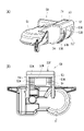
- A Perspective view of electronic device
- B Plan view of electronic device Cross-sectional view around the curved wall of electronic equipment
- Perspective view of the tire valve attached to the rim Perspective view of retainer washer
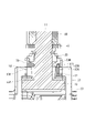
- Cross section of tire valve Cross-sectional view of a tire valve according to a modification
- FIG. 1 the tire valve 10 is attached to a rim 91 of a tire wheel 90 and used.
- the rim 91 includes a large-diameter portion 91A arranged on the outer side in the vehicle width direction, a small-diameter portion 91B arranged on the inner side in the vehicle-width direction, an upright portion 91C connecting the large-diameter portion 91A and the small-diameter portion 91B,
- a valve mounting hole 92 (corresponding to a "through hole” in the claims) is formed through the standing portion 91C.
- the right side of FIG. 1 is the distal end side of the tire valve 10, and the left side of FIG.
- the tire valve 10 has a metal valve stem 11.
- the valve stem 11 has a pair of rod-shaped locking portions 13 extending in a direction perpendicular to the central axis at the proximal end of a cylindrical valve body 12 .
- the valve body 12 has a large-diameter portion 12A on the proximal end side and a small-diameter portion 12B on the distal end side across a tapered portion 12C in the middle portion in the axial direction.
- Annular grooves 12M are formed in the axial intermediate portions of the outer surfaces of the large diameter portion 12A and the small diameter portion 12B.
- the outer surface of the rod-shaped engaging portion 13 has a flat surface 13A extending flush with the base end surface of the valve body 12 on the base end side, and an arc surface 13B having a semicircular cross section on the tip end side. .
- a valve core 20 is provided at the tip inside the valve stem 11 .
- the valve core 20 has a structure in which a direct-acting rod 22 passes through the central portion of a cylindrical core body 21 .
- a valve body 23 is provided at a portion of the direct-acting rod 22 protruding from the cylindrical core body 21 toward the proximal end.
- a coil spring (not shown) is arranged between the distal end of the cylindrical core body 21 and the distal end of the direct-acting rod 22, and the elastic force of the coil spring normally opens the base end opening 21C of the cylindrical core body 21. The valve body 23 is pressed against.
- valve stem 11 As a result, fluid cannot normally pass through the valve stem 11, and the direct-acting rod 22 is pushed from the distal end side, or the pressure on the distal end side of the valve core 20 in the valve stem 11 is the base pressure.
- the pressure on the end side becomes higher than the pressure on the end side by a certain pressure or more, the valve body 23 is separated from the base end side opening 21C of the cylindrical core body 21, and the fluid passes through the inside of the valve stem 11.
- a cap male screw portion 12D is formed on the outer peripheral surface of the tip portion of the valve stem 11, and a valve cap 25 is screwed thereon.
- An electronic device 50 is attached to the proximal end of the valve stem 11 .
- the electronic device 50 has a pressure sensor, a temperature sensor, and a wireless circuit (not shown), detects the pressure and temperature in the tire, and wirelessly transmits the detection results to a tire monitoring device (not shown) provided in the vehicle body. do.
- the tire monitoring device monitors whether there is an abnormality in the pressure and temperature in the tire based on the received detection results.
- the electronic device 50 has a case portion 51 containing a pressure sensor, a temperature sensor, and a wireless circuit, and a coupling portion 52 for coupling with the valve stem 11.
- the case portion 51 is flattened in the radial direction of the tire, and the plane shape of the case portion 51 has an irregular shape in which the tire circumferential direction is the longitudinal direction and the tire width direction is the lateral direction.
- the coupling portion 52 is arranged on a curved wall 53 that curves upward (upward in FIG. 2, outward in the tire radial direction) from the tip side surface of the case portion 51 toward the tip side, and on both side ends of the curved wall 53, A pair of connecting walls 54 connecting the curved wall 53 and the upper surface of the case portion 51 are provided.
- a long hole 53N is formed in the curved wall 53 at the center of the electronic device 50 in the longitudinal direction, the long hole 53N extending from the side surface of the tip side of the case portion 51 to a position close to the upper end.
- the width of the long hole 53N is larger than the width of the large-diameter portion 12A of the valve stem 11 and smaller than the length between the ends of the pair of rod-shaped locking portions 13.
- the inner curved surface 53A of the curved wall 53 is curved along the arcuate surface 13B of the rod-shaped engaging portion 13 of the valve stem 11. As shown in FIG.
- the curved wall 53 has metal plates 53K on both sides of the elongated hole 53N.
- the metal plate 53K has an arc shape extending along the cross-sectional shape of the curved wall 53 and is exposed on the inner curved surface 53A and the outer curved surface 53B of the curved wall 53 .
- the metal plate 53K has a plurality of through holes 53K1 and is embedded in the curved wall 53 by insert molding. It should be noted that the curved wall 53 may not be embedded with the metal plate 53K and may be composed only of resin.
- the long hole 53 ⁇ /b>N of the electronic device 50 is inserted between the pair of connecting walls 54 of the electronic device 50 while the pair of rod-shaped locking portions 13 of the valve stem 11 are accommodated between the pair of communication walls 54 of the electronic device 50 .
- the valve stem 11 is inserted through the .
- the angle of the electronic device 50 with respect to the valve stem 11 can be changed by rotating the valve stem 11 in the elongated hole 53N about the bar-shaped engaging portion 13 as an axis.
- the tire valve 10 has a retainer washer 30 (corresponding to a "ring member” in the claims) arranged on the outer surface of the valve stem 11 and a nut member 40. It is fixed to the rim 91 by sandwiching the opening edge of the valve mounting hole 92 of 91 . Specifically, the retainer washer 30 is arranged on the valve stem 11 next to the tip side of the electronic device 50 . As shown in FIGS. 2 and 7 , the retainer washer 30 has a shape having a side wall portion 32 projecting from the outer edge of the annular plate portion 31 to the tip side of the tire valve 10 .
- the retainer washer 30 is formed with an interference avoiding portion 33 (corresponding to a “notch” in the claims) that is cut linearly in a part in the circumferential direction.
- the interference avoiding portion 33 may be notched in another shape such as a curved shape instead of a straight shape.
- the retainer washer 30 is arranged in such a posture that the interference avoiding portion 33 is positioned closer to the rotation shaft side of the tire wheel 90 than the valve mounting hole 92 and is positioned at the corner portion formed by the small diameter portion 91B and the standing portion 91C of the rim 91. ing.
- a grommet 35 is attached to the inner side of the side wall portion 32 of the retainer washer 30 , and the tire valve 10 is sealed against the rim 91 by inserting the grommet 35 into the valve mounting hole 92 of the rim 91 . be.
- the nut member 40 has a tubular shape, and a female screw portion 40N is formed at the proximal end portion. Further, the nut member 40 is provided with an annular protruding portion 41 protruding from the female screw portion 40N toward the base end side. The inner surface of the annular projecting portion 41 extends flat in the axial direction and then slopes so as to connect with the female screw portion 40N. I am in touch.
- a nut male screw portion 12E is formed at the tip of the large diameter portion 12A of the valve stem 11, and a nut member 40 is screwed onto the nut male screw portion 12E.
- a washer 45 is provided on the outer surface of the valve stem 11 between the nut member 40 and the opening edge of the valve mounting hole 92 of the rim 91 .
- the tire valve 10 is attached to the rim 91 as follows. First, the valve core 20 is screwed inside the valve stem 11 . Next, the tip of the valve stem 11 is inserted into the elongated hole 53N of the electronic device 50 from the inner curved surface 53A side, and the arcuate surface 13B of the rod-shaped engaging portion 13 of the valve stem 11 is inserted into the curved wall 53 of the electronic device 50. It is brought into contact with the curved surface 53A (see FIG. 5).
- the valve stem 11 is inserted into the valve mounting hole 92 of the rim 91 from the inside.
- the lower surface of the case portion 51 of the electronic device 50 faces the small diameter portion 91B of the rim 91, and the interference avoiding portion 33 of the retainer washer 30 is positioned at the corner portion formed by the small diameter portion 91B and the standing portion 91C of the rim 91. (see Figure 2).
- the washer 45 is fitted to the valve stem 11 from the tip end side and is applied to the opening edge of the valve mounting hole 92 of the rim 91 from the outside, and the nut member 40 is screwed to the nut male screw portion 12E of the valve stem 11. do.
- the annular protrusion 41 of the nut member 40 comes into contact with the washer 45 and the washer 45 is pressed against the opening edge of the valve mounting hole 92 of the rim 91, and the grommet 35 of the retainer washer 30 is pushed. It digs into the valve mounting hole 92 .
- the opening edge of the valve mounting hole 92 of the rim 91 is sandwiched between the retainer washer 30 and the nut member 40 (the washer 45 pressed by the nut member 40 ), thereby fixing the tire valve 10 to the rim 91 .
- the metal plate 53K of the coupling portion 52 of the electronic device 50 is sandwiched between the annular plate portion 31 of the retainer washer 30 and the rod-shaped engaging portion 13 of the valve stem 11, thereby The angle of instrument 50 relative to valve stem 11 is fixed.
- the electronic device 50 is fixed at an angle such that the case portion 51 is parallel to the small diameter portion 91B of the rim 91 .
- the interference avoiding portion 33 of the retainer washer 30 consists of the small diameter portion 91B of the rim 91 and the standing portion 91C. It is necessary to rotate the retainer washer 30 so that the interference avoiding portion 33 is arranged on the lower surface side of the case portion 51 of the electronic device 50 so as to be oriented properly.
- the coupling portion 52 of the electronic device 50 is provided with the projection 53T (corresponding to the “engagement portion” in the claims), while the retainer washer 30 has a circular shape.
- the ring plate portion 31 is provided with an engagement groove 30M (corresponding to the “engagement portion” in the claims).
- one of the two metal plates 53K (the right side in FIG. 4B) is attached to the outer curved surface 53B of the curved wall 53 in the coupling portion 52 of the electronic device 50.
- a ridge 53T is arranged between the metal plate 53K) and the long hole 53N.
- the protrusion 53T extends along the elongated hole 53N, that is, along the rotational direction of the electronic device 50 with respect to the valve stem 11 .
- the annular plate portion 31 of the retainer washer 30 has an engagement member extending vertically on the right side thereof when the interference avoiding portion 33 is placed downward (the posture in FIG. 3).
- a matching groove 30M is arranged.
- the interference avoiding portion 33 of the retainer washer 30 is arranged on the lower surface side of the case portion 51 of the electronic device 50 (see FIG. 2, etc.)
- the engagement groove 30M of the retainer washer 30 is formed as shown in FIG.
- the ridges 53T of the electronic device 50 are received at this position, and the rotation of the retainer washer 30 with respect to the electronic device 50 is restricted.
- the interference avoidance portion 33 of the retainer washer 30 The electronic device 50 is arranged on the lower surface of the case portion 51 (see FIG. 2). Moreover, the protrusion 53T and the engagement groove 30M have a length that engages at any position within the rotation range of the electronic device 50 .
- the retainer washer for the electronic device 50 is engaged with the protrusion 53T and the engagement groove 30M. Since the rotation of the tire valve 10 is restricted, the retainer washer 30 can be attached to the opening edge of the valve mounting hole 92 of the rim 91 while the retainer washer 30 is arranged in the regular direction. work becomes easier.
- the retainer washer 30 and the electronic device 50 are assembled so that the interference avoiding portion 33 of the retainer washer 30 is arranged on the lower surface side of the case portion 51 of the electronic device 50, the protrusion 53T and the engagement groove 30M are formed. are engaged, the retainer washer 30 is naturally arranged in the regular direction when the protrusion 53T and the engagement groove 30M are engaged with each other.
- the retainer can be retained regardless of the angle of the electronic device 50 with respect to the valve stem 11.
- the washer 30 is oriented with respect to the electronic device 50 .
- the retainer washer 30 and the curved wall 53 of the electronic device 50 are provided with flat surfaces 30H and 53H that are adjacent to or face each other in the rotation axis direction of the electronic device 50. good too.
- the retainer washer 30 and the electronic device 50 can be assembled in only one specific orientation. It may be possible to assemble with Even in this case, once assembled at the correct position, the retainer washer 30 is attached to the rim 91 in the correct position. The mounting work of the tire valve 10 becomes easier.
- the protrusion 53T and the engagement groove 30M may be engaged only in a part of the rotation range of the electronic device 50 . Even in this case, the valve stem 11 is inserted into the valve mounting hole 92 of the rim 91 with the protrusion 53T and the engagement groove 30M engaged, and then the electronic device 50 is attached to the valve stem 11. By rotating, it is possible to assemble the retainer washer 30 and the electronic device 50 in the regular orientation.
- the electronic device 50 may be non-rotatably fixed to the valve stem 11 .
Landscapes
- Engineering & Computer Science (AREA)
- Mechanical Engineering (AREA)
- Check Valves (AREA)
Abstract
【課題】組み付け作業を容易にすることが求められている。 【解決手段】本開示のタイヤバルブ10では、電子機器50の結合部52に突条53Tが設けられる一方、リテーナワッシャ30の円環板部31に係合溝30Mが設けられていて、突条53Tと係合溝30Mとを係合させる向きで、バルブステム11に電子機器50とリテーナワッシャ30とを組み付けると、リテーナワッシャ30の干渉回避部33が電子機器50のケース部51の下面に配された状態となる。
Description
本開示は、タイヤホイールのリムの貫通孔にリムの内側から挿入されるタイヤバルブに関する。
従来、この種のタイヤバルブとして、後端部に電子機器が支持されたものが知られている(例えば、特許文献1参照)。
上述した従来のタイヤバルブにおいては、組み付け作業を容易にすることが求められている。
本開示のタイヤバルブは、タイヤホイールのリムの貫通孔に前記リムの内側から挿入されるタイヤバルブにおいて、タイヤバルブの後端部に支持される電子機器と、タイヤバルブのうち前記電子機器より前側に回転可能に嵌合されて、前記貫通孔の開口縁に宛がわれるリング部材と、前記リング部材の周方向の一部に形成され、前記タイヤホイールのうち前記貫通孔より回転軸側の内面との干渉を回避するための切欠部と、前記電子機器と前記リング部材とに設けられ、前記電子機器に対する前記リング部材の回転を規制するように係合する係合部と、を備えるタイヤバルブである。
以下、図1から図8を参照して、本開示のタイヤバルブ10について説明する。図1に示すように、タイヤバルブ10は、タイヤホイール90のリム91に取り付けられて使用される。リム91は、車幅方向の外側に配された大径部91Aと、車幅方向の内側に配された小径部91Bと、大径部91Aと小径部91Bとを接続する起立部91Cと、を有し、起立部91Cにバルブ取付孔92(特許請求の範囲中の「貫通孔」に相当する)が貫通形成されている。以降、特記しない限り、図1の右方をタイヤバルブ10の先端側、図1の左方をタイヤバルブ10の基端側とする。
図2及び図3に示すように、タイヤバルブ10は、金属製のバルブステム11を有している。バルブステム11は、円筒状のバルブ本体12の基端部に、中心軸と直交する方向に延びた1対の棒状係止部13を備えている。バルブ本体12は、軸方向の中間部のテーパ部12Cを挟んで基端側が大径部12Aとなっていて、先端側が小径部12Bとなっている。大径部12A及び小径部12Bの外側面には、軸方向の中間部に環状溝12Mがそれぞれ形成されている。棒状係止部13の外面は、基端部側が、バルブ本体12の基端面と面一に延びた平坦面13Aとなっていて、先端側が、断面半円状をなす円弧面13Bとなっている。
バルブステム11の内側には、先端部に、バルブコア20が備えられている。図2に示すように、バルブコア20は、筒形コア本体21の中心部を直動ロッド22が貫通した構造をなしている。直動ロッド22のうち筒形コア本体21から基端側に突出した部分には弁体23が備えられている。また、筒形コア本体21の先端と直動ロッド22の先端部との間には、図示しないコイルバネが配され、そのコイルバネの弾発力によって通常は筒形コア本体21の基端側開口21Cに弁体23が押し付けられている。これにより、通常は、バルブステム11内を流体が通過できないようになっていて、直動ロッド22が先端側から押されるか、或いは、バルブステム11内において、バルブコア20より先端側の圧力が基端側の圧力より一定圧以上高くなった場合に、弁体23が筒形コア本体21の基端側開口21Cから離間し、バルブステム11内を流体が通過する。また、バルブステム11の先端部の外周面にはキャップ用雄螺子部12Dが形成され、そこにバルブキャップ25が螺合装着されている。
バルブステム11の基端部には、電子機器50が取り付けられている。電子機器50は、圧力センサ、温度センサ及び無線回路(図示せず)を有し、タイヤ内の圧力及び温度を検出して、それら検出結果を車両本体に備えた図示しないタイヤ監視装置に無線送信する。タイヤ監視装置は、受信した検出結果に基づいてタイヤ内の圧力及び温度の異常の有無を監視する。
図2~図4に示すように、電子機器50は、圧力センサ、温度センサ及び無線回路を内蔵したケース部51と、バルブステム11と結合するための結合部52と、を有している。ケース部51は、タイヤの径方向に扁平になっていて、ケース部51の平面形状は、タイヤの周方向が長手方向で、タイヤ幅方向が短手方向となった異形状をなしている。
結合部52は、ケース部51の先端側側面から先端側へ向かうにつれて上方(図2における上方。タイヤ径方向の外方)へ湾曲した湾曲壁53と、湾曲壁53の両側端に配され、湾曲壁53とケース部51の上面とを連絡する1対の連絡壁54と、備える。湾曲壁53には、電子機器50の長手方向の中央に、ケース部51の先端側側面から、上端寄り位置まで延びた長孔53Nが形成されている。長孔53Nの幅は、バルブステム11の大径部12Aの幅より大きく、かつ、1対の棒状係止部13の端部同士の間の長さより小さくなっている。また、湾曲壁53の内側湾曲面53Aは、バルブステム11の棒状係止部13の円弧面13Bに沿って湾曲している。
図4及び図5に示すように、湾曲壁53には、長孔53Nの両側方に、金属板53Kが配されている。金属板53Kは、湾曲壁53の断面形状に沿って延びた円弧状をなし、湾曲壁53の内側湾曲面53Aと外側湾曲面53Bとに露出している。金属板53Kは、複数の貫通孔53K1を備え、インサート成形により湾曲壁53に埋設されている。なお、湾曲壁53に金属板53Kが埋設されず、樹脂のみから構成されていてもよい。
図6に示すように、タイヤバルブ10では、バルブステム11の1対の棒状係止部13が電子機器50の1対の連絡壁54間に収められた状態で、電子機器50の長孔53Nにバルブステム11が挿通されている。そして、バルブステム11を長孔53N内で棒状係止部13を軸に回動させることで、電子機器50のバルブステム11に対する角度を変更可能になっている。
図2及び図6に示すように、タイヤバルブ10は、バルブステム11の外側面に配されたリテーナワッシャ30(特許請求の範囲中の「リング部材」に相当する)とナット部材40とによりリム91のバルブ取付孔92の開口縁部を挟むことで、リム91に固定されている。詳細には、バルブステム11には、電子機器50の先端側の隣に、リテーナワッシャ30が配されている。図2及び図7に示すように、リテーナワッシャ30は、円環板部31の外縁からタイヤバルブ10の先端側へ突出した側壁部32を有する形状をなしている。また、リテーナワッシャ30には、周方向の一部に、直線状に切り欠かれた干渉回避部33(特許請求の範囲中の「切欠部」に相当する)が形成されている。なお、干渉回避部33は、直線状ではなく、曲線状等他の形状に切り欠かれていてもよい。
リテーナワッシャ30は、干渉回避部33が、バルブ取付孔92よりもタイヤホイール90の回転軸側に位置し、リム91の小径部91Bと起立部91Cとからなるコーナー部に位置する姿勢で配されている。また、リテーナワッシャ30には、側壁部32の内側にグロメット35が装着されていて、このグロメット35がリム91のバルブ取付孔92内に入り込むことで、タイヤバルブ10がリム91に対してシールされる。
図2に示すように、ナット部材40は、筒状をなし、基端部に雌螺子部40Nが形成されている。また、ナット部材40には、雌螺子部40Nより基端側へ突出した環状突出部41が設けられている。環状突出部41の内側面は、軸方向に平坦に延びたのち雌螺子部40Nに連なるように傾斜していて、環状突出部41の外側面は、拡径しながらナット部材40の外側面に連絡している。
バルブステム11の大径部12Aの先端部には、ナット用雄螺子部12Eが形成され、このナット用雄螺子部12Eにナット部材40が螺合されている。また、バルブステム11の外側面には、ナット部材40とリム91のバルブ取付孔92の開口縁部との間に、ワッシャ45が備えられている。
タイヤバルブ10は以下のようにしてリム91に取り付けられる。まず、バルブステム11の内側にバルブコア20を螺合する。次いで、バルブステム11の先端部を、電子機器50の長孔53Nに内側湾曲面53A側から挿入し、バルブステム11の棒状係止部13の円弧面13Bを電子機器50の湾曲壁53の内側湾曲面53Aに当接させる(図5参照)。
その後、グロメット35が装着されたリテーナワッシャ30をバルブステム11に先端側から嵌合させたのち、そのバルブステム11をリム91のバルブ取付孔92に内側から挿入する。このとき、電子機器50のケース部51の下面をリム91の小径部91Bに向けると共に、リテーナワッシャ30の干渉回避部33を、リム91の小径部91Bと起立部91Cとからなるコーナー部に位置させる(図2参照)。
次いで、バルブステム11にワッシャ45を先端側から嵌合させてリム91のバルブ取付孔92の開口縁部に外側から宛がい、ナット部材40をバルブステム11のナット用雄螺子部12Eに螺合する。ナット部材40を締め付けていくと、ナット部材40の環状突出部41がワッシャ45に当接してワッシャ45がリム91のバルブ取付孔92の開口縁部に押し付けられるとともに、リテーナワッシャ30のグロメット35がバルブ取付孔92内に食い込んでいく。これにより、リム91のバルブ取付孔92の開口縁部がリテーナワッシャ30とナット部材40(ナット部材40により押し付けられるワッシャ45)とに挟み付けられ、タイヤバルブ10がリム91に固定される。
また、ナット部材40を締め付けると、リテーナワッシャ30の円環板部31と、バルブステム11の棒状係止部13との間に、電子機器50の結合部52の金属板53Kが挟持され、電子機器50のバルブステム11に対する角度が固定される。本実施形態では、図2に示すように、電子機器50は、ケース部51がリム91の小径部91Bと平行になる角度で固定されている。
ところで、バルブステム11をリム91のバルブ取付孔92に挿入するときに、干渉回避部33が電子機器50のケース部51の下面側に配されていないと、以下のような問題が起こり得る。即ち、例えば、電子機器50のケース部51の下面がリム91の小径部91B側を向くように挿入すると、リテーナワッシャ30の干渉回避部33がリム91の小径部91Bと起立部91Cとからなるコーナー部に配されず、リテーナワッシャ30を回転させて正規の向き(干渉回避部33が電子機器50のケース部51の下面側に配される向き)に直す必要が生じる。
これに対し、本実施形態のタイヤバルブ10では、電子機器50の結合部52に突条53T(特許請求の範囲中の「係合部」に相当する)が設けられる一方、リテーナワッシャ30の円環板部31に係合溝30M(特許請求の範囲中の「係合部」に相当する)が設けられている。詳細には、図4に示すように、電子機器50における結合部52のうち、湾曲壁53の外側湾曲面53Bには、2つの金属板53Kのうちの1つ(図4(B)における右側の金属板53K)と長孔53Nとの間に、突条53Tが配されている。突条53Tは、長孔53Nに沿って、即ち、電子機器50のバルブステム11に対する回動方向に沿って延びている。
図3及び図7に示すように、リテーナワッシャ30の円環板部31には、干渉回避部33を下に配した姿勢(図3における姿勢)での右側部に、上下方向に延びた係合溝30Mが配されている。そして、リテーナワッシャ30の干渉回避部33が電子機器50のケース部51の下面側に配されている状態では(図2等参照)、図8に示すように、リテーナワッシャ30の係合溝30Mに電子機器50の突条53Tが受容され、電子機器50に対するリテーナワッシャ30の回転が規制される。換言すれば、突条53Tと係合溝30Mとを係合させる向きで、バルブステム11に電子機器50とリテーナワッシャ30とを組み付けると(図8参照)、リテーナワッシャ30の干渉回避部33が電子機器50のケース部51の下面に配された状態となる(図2参照)。また、突条53Tと係合溝30Mとは、電子機器50の回動範囲の任意の位置で係合する長さになっている。
本実施形態のタイヤバルブ10によれば、バルブステム11に電子機器50とリテーナワッシャ30とを組み付ける際に、突条53Tと係合溝30Mとを係合させることで、電子機器50に対するリテーナワッシャ30の回転が規制されるので、リテーナワッシャ30が正規の向きに配されたまま、リテーナワッシャ30をリム91のバルブ取付孔92の開口縁部に宛てがうことができ、タイヤバルブ10の組み付け作業が容易になる。
しかも、リテーナワッシャ30の干渉回避部33が電子機器50のケース部51の下面側に配される向きでリテーナワッシャ30と電子機器50とを組み付けたときにのみ突条53Tと係合溝30Mとが係合するので、突条53Tと係合溝30Mとを係合させると、自ずとリテーナワッシャ30が正規の向きに配される。
また、突条53Tと係合溝30Mとは、電子機器50の回動範囲の任意の位置で係合するので、電子機器50がバルブステム11に対してどのような角度に配されてもリテーナワッシャ30の電子機器50に対する向きが定められる。
[他の実施形態]
(1)図9に示すように、突条30Tがリテーナワッシャ30に配され、係合溝53Mが電子機器50の湾曲壁53に配された構成であってもよい。
(1)図9に示すように、突条30Tがリテーナワッシャ30に配され、係合溝53Mが電子機器50の湾曲壁53に配された構成であってもよい。
(2)図10に示すように、リテーナワッシャ30と電子機器50の湾曲壁53とに、電子機器50の回動軸方向で互いに隣接又は対向する平坦面30H,53Hを備えた構成であってもよい。
(3)上記実施形態では、リテーナワッシャ30と電子機器50とが、特定の一向きでのみ組み付け可能な構成であったが、リテーナワッシャ30の電子機器50に対する回転が規制されれば複数の向きで組み付け可能であってもよい。この場合であっても、一旦正規の位置で組み付けられると、リテーナワッシャ30が正規の位置に配された状態でリム91に取り付けられるので、リテーナワッシャ30が電子機器50に対して回転可能な構成よりもタイヤバルブ10の組み付け作業が容易になる。
(4)突条53Tと係合溝30Mとは、電子機器50の回動範囲の一部でのみ係合可能であってもよい。この場合であっても、突条53Tと係合溝30Mとを係合させた状態でバルブステム11をリム91のバルブ取付孔92に挿入し、その後、電子機器50をバルブステム11に対して回動させることで、リテーナワッシャ30と電子機器50とを正規の向きで組み付けることが可能となる。
(5)電子機器50がバルブステム11に対して回動不能に固定されていてもよい。
なお、本明細書及び図面には、特許請求の範囲に含まれる技術の具体例が開示されているが、特許請求の範囲に記載の技術は、これら具体例に限定されるものではなく、具体例を様々に変形、変更したものも含み、また、具体例から一部を単独で取り出したものも含む。
10 タイヤバルブ
11 バルブステム
12 バルブ本体
13 棒状係止部
30 リテーナワッシャ(リング部材)
30M 係合溝(係合部)
33 干渉回避部(切欠部)
40 ナット部材
50 電子機器
51 ケース部
52 結合部
53 湾曲壁
53K 金属板
53N 長孔
53T 突条(係合部)
91 リム
92 バルブ取付孔
11 バルブステム
12 バルブ本体
13 棒状係止部
30 リテーナワッシャ(リング部材)
30M 係合溝(係合部)
33 干渉回避部(切欠部)
40 ナット部材
50 電子機器
51 ケース部
52 結合部
53 湾曲壁
53K 金属板
53N 長孔
53T 突条(係合部)
91 リム
92 バルブ取付孔
Claims (5)
- タイヤホイールのリムの貫通孔に前記リムの内側から挿入されるタイヤバルブにおいて、
タイヤバルブの後端部に支持される電子機器と、
タイヤバルブのうち前記電子機器より前側に回転可能に嵌合されて、前記貫通孔の開口縁に宛がわれるリング部材と、
前記リング部材の周方向の一部に形成され、前記タイヤホイールのうち前記貫通孔より回転軸側の内面との干渉を回避するための切欠部と、
前記電子機器と前記リング部材とに設けられ、前記電子機器に対する前記リング部材の回転を規制するように係合する係合部と、を備えるタイヤバルブ。 - 前記電子機器及び前記リング部材の前記係合部は、タイヤバルブを前記タイヤホイールに取り付けたときに前記切欠部が前記タイヤホイールのうち前記貫通孔より回転軸側の内面に隣接する向きで、前記リング部材と前記電子機器とが組み付けられたときにのみ係合する請求項1に記載のタイヤバルブ。
- 前記電子機器は、前記貫通孔への挿入方向と直交する回転軸を中心に回動可能に支持され、
前記電子機器及び前記リング部材の前記係合部同士が、前記電子機器の任意の回動位置で係合する請求項1又は2に記載のタイヤバルブ。 - 前記電子機器及び前記リング部材の一方の前記係合部は、前記電子機器の回動方向に沿って延びる凹状又は突状をなし、
他方の係合部は、前記一方の係合部の長手方向の一部に係合する突状又は凹状をなしている請求項3に記載のタイヤバルブ。 - 前記電子機器及び前記リング部材の一方の前記係合部は、前記電子機器の回動半径方向と平行な面であり、他方の係合部が、前記一方の係合部に対して前記電子機器の回転軸方向から隣接している請求項3に記載のタイヤバルブ。
Priority Applications (1)
| Application Number | Priority Date | Filing Date | Title |
|---|---|---|---|
| PCT/JP2021/019724 WO2022249264A1 (ja) | 2021-05-25 | 2021-05-25 | タイヤバルブ |
Applications Claiming Priority (1)
| Application Number | Priority Date | Filing Date | Title |
|---|---|---|---|
| PCT/JP2021/019724 WO2022249264A1 (ja) | 2021-05-25 | 2021-05-25 | タイヤバルブ |
Publications (1)
| Publication Number | Publication Date |
|---|---|
| WO2022249264A1 true WO2022249264A1 (ja) | 2022-12-01 |
Family
ID=84229773
Family Applications (1)
| Application Number | Title | Priority Date | Filing Date |
|---|---|---|---|
| PCT/JP2021/019724 Ceased WO2022249264A1 (ja) | 2021-05-25 | 2021-05-25 | タイヤバルブ |
Country Status (1)
| Country | Link |
|---|---|
| WO (1) | WO2022249264A1 (ja) |
Cited By (1)
| Publication number | Priority date | Publication date | Assignee | Title |
|---|---|---|---|---|
| US12403731B2 (en) | 2021-09-15 | 2025-09-02 | Pacific Industrial Co., Ltd. | Tire valve |
Citations (3)
| Publication number | Priority date | Publication date | Assignee | Title |
|---|---|---|---|---|
| JP2004066848A (ja) * | 2002-08-01 | 2004-03-04 | Pacific Ind Co Ltd | タイヤ状態監視装置の送信機 |
| JP2007326384A (ja) * | 2006-06-06 | 2007-12-20 | Topy Ind Ltd | 車両のホイールアッセンブリ |
| JP2016132366A (ja) * | 2015-01-20 | 2016-07-25 | 本田技研工業株式会社 | クランプインバルブ付きホイール |
-
2021
- 2021-05-25 WO PCT/JP2021/019724 patent/WO2022249264A1/ja not_active Ceased
Patent Citations (3)
| Publication number | Priority date | Publication date | Assignee | Title |
|---|---|---|---|---|
| JP2004066848A (ja) * | 2002-08-01 | 2004-03-04 | Pacific Ind Co Ltd | タイヤ状態監視装置の送信機 |
| JP2007326384A (ja) * | 2006-06-06 | 2007-12-20 | Topy Ind Ltd | 車両のホイールアッセンブリ |
| JP2016132366A (ja) * | 2015-01-20 | 2016-07-25 | 本田技研工業株式会社 | クランプインバルブ付きホイール |
Cited By (1)
| Publication number | Priority date | Publication date | Assignee | Title |
|---|---|---|---|---|
| US12403731B2 (en) | 2021-09-15 | 2025-09-02 | Pacific Industrial Co., Ltd. | Tire valve |
Similar Documents
| Publication | Publication Date | Title |
|---|---|---|
| JP4522953B2 (ja) | タイヤバルブユニット | |
| US12403731B2 (en) | Tire valve | |
| CN113272159A (zh) | 适配器、轮胎参数监测系统和用于将轮胎参数监测系统安装到轮辋上的方法 | |
| WO2022249264A1 (ja) | タイヤバルブ | |
| EP1681477A1 (en) | Snap ring | |
| EP3450222B1 (en) | Tire condition detecting apparatus, clamp-in valve and tire valve unit | |
| US11724553B2 (en) | Valve system, tire parameter monitoring system and method for mounting a tire parameter monitoring system onto a wheel rim of a vehicle | |
| JP6704986B2 (ja) | タイヤ状態検出装置 | |
| JP2015042543A (ja) | タイヤバルブユニット | |
| US11385117B2 (en) | Tire pressure monitoring module with thru-valve construction | |
| JPH0988993A (ja) | 弾性軸継手 | |
| JP7255018B2 (ja) | タイヤバルブ及びタイヤ状態監視装置 | |
| JPH11294472A (ja) | 回転体固定具 | |
| JP2739456B2 (ja) | 管継手 | |
| WO2025163777A1 (ja) | タイヤバルブ及びカバースリーブ | |
| JP2557387B2 (ja) | 波形管接続具 | |
| JP2008008484A (ja) | ボールジョイント | |
| JP2008221974A (ja) | ステアリングロールコネクタ | |
| KR100764210B1 (ko) | 스티어링장치의 이너 볼 조인트용 볼 시트 | |
| JP2562633Y2 (ja) | スリーブクランプ | |
| JP3056707U (ja) | 軸止め機構 | |
| JPH0524812Y2 (ja) | ||
| JP3604363B2 (ja) | 配管用キャップ | |
| JP2008003804A (ja) | ツマミ本体、ツマミ及びツマミ装置 | |
| JPH10331832A (ja) | 戻り止め座金 |
Legal Events
| Date | Code | Title | Description |
|---|---|---|---|
| 121 | Ep: the epo has been informed by wipo that ep was designated in this application |
Ref document number: 21942920 Country of ref document: EP Kind code of ref document: A1 |
|
| NENP | Non-entry into the national phase |
Ref country code: DE |
|
| 122 | Ep: pct application non-entry in european phase |
Ref document number: 21942920 Country of ref document: EP Kind code of ref document: A1 |
|
| NENP | Non-entry into the national phase |
Ref country code: JP |