WO2022249257A1 - 狭帯域化モジュール、ガスレーザ装置、及び電子デバイスの製造方法 - Google Patents
狭帯域化モジュール、ガスレーザ装置、及び電子デバイスの製造方法 Download PDFInfo
- Publication number
- WO2022249257A1 WO2022249257A1 PCT/JP2021/019662 JP2021019662W WO2022249257A1 WO 2022249257 A1 WO2022249257 A1 WO 2022249257A1 JP 2021019662 W JP2021019662 W JP 2021019662W WO 2022249257 A1 WO2022249257 A1 WO 2022249257A1
- Authority
- WO
- WIPO (PCT)
- Prior art keywords
- mirror
- adhesive
- holding portion
- adjacent
- light
- Prior art date
- Legal status (The legal status is an assumption and is not a legal conclusion. Google has not performed a legal analysis and makes no representation as to the accuracy of the status listed.)
- Ceased
Links
Images












Classifications
-
- H—ELECTRICITY
- H01—ELECTRIC ELEMENTS
- H01S—DEVICES USING THE PROCESS OF LIGHT AMPLIFICATION BY STIMULATED EMISSION OF RADIATION [LASER] TO AMPLIFY OR GENERATE LIGHT; DEVICES USING STIMULATED EMISSION OF ELECTROMAGNETIC RADIATION IN WAVE RANGES OTHER THAN OPTICAL
- H01S3/00—Lasers, i.e. devices using stimulated emission of electromagnetic radiation in the infrared, visible or ultraviolet wave range
- H01S3/10—Controlling the intensity, frequency, phase, polarisation or direction of the emitted radiation, e.g. switching, gating, modulating or demodulating
- H01S3/13—Stabilisation of laser output parameters, e.g. frequency or amplitude
- H01S3/139—Stabilisation of laser output parameters, e.g. frequency or amplitude by controlling the mutual position or the reflecting properties of the reflectors of the cavity, e.g. by controlling the cavity length
-
- H—ELECTRICITY
- H01—ELECTRIC ELEMENTS
- H01S—DEVICES USING THE PROCESS OF LIGHT AMPLIFICATION BY STIMULATED EMISSION OF RADIATION [LASER] TO AMPLIFY OR GENERATE LIGHT; DEVICES USING STIMULATED EMISSION OF ELECTROMAGNETIC RADIATION IN WAVE RANGES OTHER THAN OPTICAL
- H01S3/00—Lasers, i.e. devices using stimulated emission of electromagnetic radiation in the infrared, visible or ultraviolet wave range
- H01S3/10—Controlling the intensity, frequency, phase, polarisation or direction of the emitted radiation, e.g. switching, gating, modulating or demodulating
- H01S3/13—Stabilisation of laser output parameters, e.g. frequency or amplitude
- H01S3/136—Stabilisation of laser output parameters, e.g. frequency or amplitude by controlling devices placed within the cavity
-
- G—PHYSICS
- G03—PHOTOGRAPHY; CINEMATOGRAPHY; ANALOGOUS TECHNIQUES USING WAVES OTHER THAN OPTICAL WAVES; ELECTROGRAPHY; HOLOGRAPHY
- G03F—PHOTOMECHANICAL PRODUCTION OF TEXTURED OR PATTERNED SURFACES, e.g. FOR PRINTING, FOR PROCESSING OF SEMICONDUCTOR DEVICES; MATERIALS THEREFOR; ORIGINALS THEREFOR; APPARATUS SPECIALLY ADAPTED THEREFOR
- G03F7/00—Photomechanical, e.g. photolithographic, production of textured or patterned surfaces, e.g. printing surfaces; Materials therefor, e.g. comprising photoresists; Apparatus specially adapted therefor
- G03F7/70—Microphotolithographic exposure; Apparatus therefor
- G03F7/70008—Production of exposure light, i.e. light sources
- G03F7/70025—Production of exposure light, i.e. light sources by lasers
-
- H—ELECTRICITY
- H01—ELECTRIC ELEMENTS
- H01S—DEVICES USING THE PROCESS OF LIGHT AMPLIFICATION BY STIMULATED EMISSION OF RADIATION [LASER] TO AMPLIFY OR GENERATE LIGHT; DEVICES USING STIMULATED EMISSION OF ELECTROMAGNETIC RADIATION IN WAVE RANGES OTHER THAN OPTICAL
- H01S3/00—Lasers, i.e. devices using stimulated emission of electromagnetic radiation in the infrared, visible or ultraviolet wave range
- H01S3/10—Controlling the intensity, frequency, phase, polarisation or direction of the emitted radiation, e.g. switching, gating, modulating or demodulating
- H01S3/106—Controlling the intensity, frequency, phase, polarisation or direction of the emitted radiation, e.g. switching, gating, modulating or demodulating by controlling devices placed within the cavity
-
- H—ELECTRICITY
- H01—ELECTRIC ELEMENTS
- H01S—DEVICES USING THE PROCESS OF LIGHT AMPLIFICATION BY STIMULATED EMISSION OF RADIATION [LASER] TO AMPLIFY OR GENERATE LIGHT; DEVICES USING STIMULATED EMISSION OF ELECTROMAGNETIC RADIATION IN WAVE RANGES OTHER THAN OPTICAL
- H01S3/00—Lasers, i.e. devices using stimulated emission of electromagnetic radiation in the infrared, visible or ultraviolet wave range
- H01S3/10—Controlling the intensity, frequency, phase, polarisation or direction of the emitted radiation, e.g. switching, gating, modulating or demodulating
- H01S3/13—Stabilisation of laser output parameters, e.g. frequency or amplitude
- H01S3/1305—Feedback control systems
-
- G—PHYSICS
- G02—OPTICS
- G02B—OPTICAL ELEMENTS, SYSTEMS OR APPARATUS
- G02B26/00—Optical devices or arrangements for the control of light using movable or deformable optical elements
- G02B26/08—Optical devices or arrangements for the control of light using movable or deformable optical elements for controlling the direction of light
- G02B26/0816—Optical devices or arrangements for the control of light using movable or deformable optical elements for controlling the direction of light by means of one or more reflecting elements
-
- G—PHYSICS
- G02—OPTICS
- G02B—OPTICAL ELEMENTS, SYSTEMS OR APPARATUS
- G02B27/00—Optical systems or apparatus not provided for by any of the groups G02B1/00 - G02B26/00, G02B30/00
- G02B27/42—Diffraction optics, i.e. systems including a diffractive element being designed for providing a diffractive effect
- G02B27/4233—Diffraction optics, i.e. systems including a diffractive element being designed for providing a diffractive effect having a diffractive element [DOE] contributing to a non-imaging application
-
- G—PHYSICS
- G02—OPTICS
- G02B—OPTICAL ELEMENTS, SYSTEMS OR APPARATUS
- G02B7/00—Mountings, adjusting means, or light-tight connections, for optical elements
- G02B7/18—Mountings, adjusting means, or light-tight connections, for optical elements for prisms; for mirrors
- G02B7/182—Mountings, adjusting means, or light-tight connections, for optical elements for prisms; for mirrors for mirrors
- G02B7/1821—Mountings, adjusting means, or light-tight connections, for optical elements for prisms; for mirrors for mirrors for rotating or oscillating mirrors
-
- H—ELECTRICITY
- H01—ELECTRIC ELEMENTS
- H01S—DEVICES USING THE PROCESS OF LIGHT AMPLIFICATION BY STIMULATED EMISSION OF RADIATION [LASER] TO AMPLIFY OR GENERATE LIGHT; DEVICES USING STIMULATED EMISSION OF ELECTROMAGNETIC RADIATION IN WAVE RANGES OTHER THAN OPTICAL
- H01S3/00—Lasers, i.e. devices using stimulated emission of electromagnetic radiation in the infrared, visible or ultraviolet wave range
- H01S3/02—Constructional details
-
- H—ELECTRICITY
- H01—ELECTRIC ELEMENTS
- H01S—DEVICES USING THE PROCESS OF LIGHT AMPLIFICATION BY STIMULATED EMISSION OF RADIATION [LASER] TO AMPLIFY OR GENERATE LIGHT; DEVICES USING STIMULATED EMISSION OF ELECTROMAGNETIC RADIATION IN WAVE RANGES OTHER THAN OPTICAL
- H01S3/00—Lasers, i.e. devices using stimulated emission of electromagnetic radiation in the infrared, visible or ultraviolet wave range
- H01S3/02—Constructional details
- H01S3/03—Constructional details of gas laser discharge tubes
- H01S3/034—Optical devices within, or forming part of, the tube, e.g. windows, mirrors
-
- H—ELECTRICITY
- H01—ELECTRIC ELEMENTS
- H01S—DEVICES USING THE PROCESS OF LIGHT AMPLIFICATION BY STIMULATED EMISSION OF RADIATION [LASER] TO AMPLIFY OR GENERATE LIGHT; DEVICES USING STIMULATED EMISSION OF ELECTROMAGNETIC RADIATION IN WAVE RANGES OTHER THAN OPTICAL
- H01S3/00—Lasers, i.e. devices using stimulated emission of electromagnetic radiation in the infrared, visible or ultraviolet wave range
- H01S3/05—Construction or shape of optical resonators; Accommodation of active medium therein; Shape of active medium
- H01S3/08—Construction or shape of optical resonators or components thereof
- H01S3/08004—Construction or shape of optical resonators or components thereof incorporating a dispersive element, e.g. a prism for wavelength selection
-
- H—ELECTRICITY
- H01—ELECTRIC ELEMENTS
- H01S—DEVICES USING THE PROCESS OF LIGHT AMPLIFICATION BY STIMULATED EMISSION OF RADIATION [LASER] TO AMPLIFY OR GENERATE LIGHT; DEVICES USING STIMULATED EMISSION OF ELECTROMAGNETIC RADIATION IN WAVE RANGES OTHER THAN OPTICAL
- H01S3/00—Lasers, i.e. devices using stimulated emission of electromagnetic radiation in the infrared, visible or ultraviolet wave range
- H01S3/05—Construction or shape of optical resonators; Accommodation of active medium therein; Shape of active medium
- H01S3/08—Construction or shape of optical resonators or components thereof
- H01S3/08004—Construction or shape of optical resonators or components thereof incorporating a dispersive element, e.g. a prism for wavelength selection
- H01S3/08009—Construction or shape of optical resonators or components thereof incorporating a dispersive element, e.g. a prism for wavelength selection using a diffraction grating
-
- H—ELECTRICITY
- H01—ELECTRIC ELEMENTS
- H01S—DEVICES USING THE PROCESS OF LIGHT AMPLIFICATION BY STIMULATED EMISSION OF RADIATION [LASER] TO AMPLIFY OR GENERATE LIGHT; DEVICES USING STIMULATED EMISSION OF ELECTROMAGNETIC RADIATION IN WAVE RANGES OTHER THAN OPTICAL
- H01S3/00—Lasers, i.e. devices using stimulated emission of electromagnetic radiation in the infrared, visible or ultraviolet wave range
- H01S3/10—Controlling the intensity, frequency, phase, polarisation or direction of the emitted radiation, e.g. switching, gating, modulating or demodulating
- H01S3/105—Controlling the intensity, frequency, phase, polarisation or direction of the emitted radiation, e.g. switching, gating, modulating or demodulating by controlling the mutual position or the reflecting properties of the reflectors of the cavity, e.g. by controlling the cavity length
-
- H—ELECTRICITY
- H01—ELECTRIC ELEMENTS
- H01S—DEVICES USING THE PROCESS OF LIGHT AMPLIFICATION BY STIMULATED EMISSION OF RADIATION [LASER] TO AMPLIFY OR GENERATE LIGHT; DEVICES USING STIMULATED EMISSION OF ELECTROMAGNETIC RADIATION IN WAVE RANGES OTHER THAN OPTICAL
- H01S3/00—Lasers, i.e. devices using stimulated emission of electromagnetic radiation in the infrared, visible or ultraviolet wave range
- H01S3/14—Lasers, i.e. devices using stimulated emission of electromagnetic radiation in the infrared, visible or ultraviolet wave range characterised by the material used as the active medium
- H01S3/22—Gases
-
- H—ELECTRICITY
- H01—ELECTRIC ELEMENTS
- H01S—DEVICES USING THE PROCESS OF LIGHT AMPLIFICATION BY STIMULATED EMISSION OF RADIATION [LASER] TO AMPLIFY OR GENERATE LIGHT; DEVICES USING STIMULATED EMISSION OF ELECTROMAGNETIC RADIATION IN WAVE RANGES OTHER THAN OPTICAL
- H01S3/00—Lasers, i.e. devices using stimulated emission of electromagnetic radiation in the infrared, visible or ultraviolet wave range
- H01S3/14—Lasers, i.e. devices using stimulated emission of electromagnetic radiation in the infrared, visible or ultraviolet wave range characterised by the material used as the active medium
- H01S3/22—Gases
- H01S3/223—Gases the active gas being polyatomic, i.e. containing two or more atoms
- H01S3/225—Gases the active gas being polyatomic, i.e. containing two or more atoms comprising an excimer or exciplex
Definitions
- the present disclosure relates to a band narrowing module, a gas laser device, and a method of manufacturing an electronic device.
- a KrF excimer laser device that outputs a laser beam with a wavelength of about 248.0 nm and an ArF excimer laser device that outputs a laser beam with a wavelength of about 193.4 nm are used.
- the spectral line width of the spontaneous oscillation light of the KrF excimer laser device and the ArF excimer laser device is as wide as 350 pm to 400 pm. Therefore, if the projection lens is made of a material that transmits ultraviolet light, such as KrF and ArF laser light, chromatic aberration may occur. As a result, resolution can be reduced. Therefore, it is necessary to narrow the spectral line width of the laser light output from the gas laser device to such an extent that the chromatic aberration can be ignored. Therefore, in the laser resonator of the gas laser device, a line narrow module (LNM) including a band narrowing element (etalon, grating, etc.) is provided in order to narrow the spectral line width.
- LNM line narrow module
- a gas laser device whose spectral line width is narrowed will be referred to as a band-narrowed gas laser device.
- a band narrowing module includes a prism, a reflecting surface that reflects light transmitted through the prism, a first adjacent surface and a second adjacent surface that are adjacent to the reflecting surface, and an opposing surface that faces the reflecting surface.
- a grating that disperses the wavelength of light reflected by the reflecting surface; a holding portion that holds the mirror; a first adhesive that adheres the mirror to the holder; a second adhesive that is provided between the holder and the second adjacent surface and adheres the mirror to the holder; and a drive unit that rotates the holding unit so that the mirror rotates around the axis, wherein the second adhesive is parallel to the axis and passes through the center of the mirror when the reflecting surface is viewed from the front. may be located on the side opposite to the first adhesive with respect to .
- a gas laser device includes a band narrowing module, and the band narrowing module includes a prism, a reflecting surface that reflects light passing through the prism, a first adjacent surface adjacent to the reflecting surface, and a second adjacent surface.
- a mirror including a surface and an opposing surface facing the reflecting surface; a grating that wavelength-disperses the light reflected by the reflecting surface; a holding portion that holds the mirror; a first adhesive provided between and the facing surface for adhering the mirror to the holding portion; and a second adhesive provided between the holding portion and the second adjacent surface for adhering the mirror to the holding portion; and a driving unit for rotating the holding unit so that the mirror rotates about the line perpendicular to the plane on which the light is wavelength-dispersed, and the second adhesive is arranged on the axis when the reflecting surface is viewed from the front.
- a driving unit for rotating the holding unit so that the mirror rotates about the line perpendicular to the plane on which the light is wavelength-dispersed, and the second adhesive is arranged on the axis when the reflecting surface is viewed from the front.
- a method for manufacturing an electronic device includes a prism, a reflective surface that reflects light transmitted through the prism, a first adjacent surface and a second adjacent surface that are adjacent to the reflective surface, and an opposing surface that faces the reflective surface.
- a grating for wavelength-dispersing light reflected by the reflecting surface includes a holding portion for holding the mirror; a first adhesive for adhering the mirror to the holding portion; a second adhesive provided between the holding portion and the second adjacent surface for adhering the mirror to the holding portion; a driving unit for rotating the holding unit so that the mirror rotates around the axis about the line, wherein the second adhesive has a center parallel to the axis and passing through the center of the mirror when the reflecting surface is viewed from the front.
- a laser beam is generated by a gas laser device having a band narrowing module located on the opposite side of the line from the first adhesive, and the laser beam is output to an exposure device to manufacture an electronic device.
- a laser beam may be exposed on the photosensitive substrate inside.
- FIG. 1 is a schematic diagram showing an example of the overall configuration of an electronic device manufacturing apparatus.
- FIG. 2 is a schematic diagram showing an example of the overall configuration of a gas laser device of a comparative example.
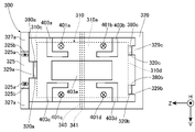
- FIG. 3 is a schematic diagram showing a first schematic configuration example of a mirror unit in a comparative example. 4 is a front view of the mirror unit shown in FIG. 3.
- FIG. 5 is a schematic diagram showing a second schematic configuration example of a mirror unit in a comparative example. 6 is a front view of the mirror unit shown in FIG. 5.
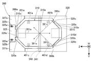
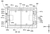
- FIG. FIG. 7 is a schematic diagram showing a schematic configuration example of a mirror unit according to the first embodiment.
- FIG. 8 is a front view of the mirror unit shown in FIG. 7.
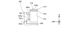
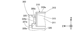
- FIG. 9 is a side view of the mirror unit viewed from the plate member side.
- 10 is a front view of a mirror unit in Modification 1 of Embodiment 1.
- FIG. 11 is a schematic diagram showing a schematic configuration example of a mirror unit in Modification 2 of Embodiment 1.
- FIG. 12 is a front view of the mirror unit shown in FIG. 11.
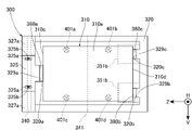
- FIG. 13 is a front view of a mirror unit according to Embodiment 2.
- FIG. 14 is a front view of a mirror unit in Modification 1 of Embodiment 2.
- FIG. 15 is a front view of a mirror unit in Modification 2 of Embodiment 2.
- FIG. 16 is a front view of a mirror unit according to Embodiment 3.
- FIG. 17 is a front view of a mirror unit in a modification of Embodiment 3.
- FIG. 18 is an enlarged view of the periphery of the adhesive in Embodiment 4.
- FIG. 19 is an enlarged view of the periphery of the adhesive in the modified example of Embodiment 4.
- FIG. 20 is a front view of a mirror unit according to Embodiment 5.
- FIG. 21A and 21B are diagrams for explaining the arrangement of the drive units according to the sixth embodiment.
- FIG. FIG. 22 is a schematic diagram showing a schematic configuration example of a mirror unit in a modified example of the sixth embodiment.
- 23A and 23B are diagrams for explaining the arrangement of the drive units in the modification of the sixth embodiment.
- FIG. 1 is a schematic diagram showing an example of the overall schematic configuration of an electronic device manufacturing apparatus used in an electronic device exposure process.
- the manufacturing apparatus used in the exposure process includes a gas laser device 100 and an exposure device 200.
- Exposure apparatus 200 includes an illumination optical system 210 including a plurality of mirrors 211 , 212 and 213 and a projection optical system 220 .
- the illumination optical system 210 illuminates the reticle pattern on the reticle stage RT with laser light incident from the gas laser device 100 .
- the projection optical system 220 reduces and projects the laser light transmitted through the reticle to form an image on a workpiece (not shown) placed on the workpiece table WT.
- the workpiece is a photosensitive substrate, such as a semiconductor wafer, to which photoresist is applied.
- the exposure apparatus 200 synchronously translates the reticle stage RT and the workpiece table WT to expose the workpiece to laser light reflecting the reticle pattern.
- a semiconductor device which is an electronic device, can be manufactured by transferring a device pattern onto a semiconductor wafer through the exposure process as described above.
- FIG. 2 is a schematic diagram showing an example of the overall configuration of the gas laser device 100 of this example.
- Gas laser device 100 is, for example, an ArF excimer laser device that uses a mixed gas containing argon (Ar), fluorine ( F2 ), and neon (Ne). In this case, the gas laser device 100 outputs pulsed laser light with a center wavelength of approximately 193.4 nm.
- the gas laser device 100 may be a gas laser device other than an ArF excimer laser device, for example, a KrF excimer laser device using a mixed gas containing krypton (Kr), F 2 and Ne. In this case, the gas laser device 100 emits pulsed laser light with a central wavelength of about 248.0 nm.
- a mixed gas containing Ar, F 2 and Ne as laser media and a mixed gas containing Kr, F 2 and Ne as laser media are sometimes called laser gas.
- High-purity nitrogen (N 2 ) or helium (He) may be used instead of Ne in the mixed gas used in each of the ArF excimer laser device and the KrF excimer laser device.
- the gas laser device 100 of this example includes a housing 110, and a laser oscillator 130, a detector 151, and a processor 190 arranged in the internal space of the housing 110 as main components.
- the laser oscillator 130 includes a chamber device CH, a charger (not shown), a pulsed power module (not shown), a band narrowing module 60, and an output coupling mirror 70 as main components.
- FIG. 2 shows the internal configuration of the chamber device CH viewed from a direction substantially perpendicular to the traveling direction of the laser light.
- the chamber device CH mainly includes a housing 30, a pair of windows 31a and 31b, and a pair of electrodes 32a and 32b.
- the direction parallel to the optical axis direction of the pulsed laser beam emitted from the chamber device CH will be described as the Z direction, the direction perpendicular to the Z direction as the H direction, and the direction perpendicular to the Z and H directions as the V direction.
- the housing 30 is supplied with the laser gas from a laser gas supply device (not shown) through a pipe (not shown) into the internal space of the housing 30, and seals the laser gas in the internal space. Light generated by excitation of the laser gas travels to windows 31a and 31b.
- the windows 31a and 31b are provided in the housing 30 at positions facing each other.
- the window 31a is positioned on the front side in the traveling direction of the laser light from the gas laser device 100 to the exposure device 200, and the window 31b is positioned on the rear side in the traveling direction.
- the windows 31a and 31b are tilted at a Brewster angle with respect to the traveling direction of the laser light so as to suppress the reflection of the P-polarized light of the laser light.
- the window 31a is arranged in a hole in the wall surface on the front side of the housing 30, and the window 31b is arranged in a hole in the wall surface on the rear side of the housing 30. As shown in FIG.
- the longitudinal direction of the electrodes 32a and 32b is along the traveling direction of the laser beam, and the electrodes 32a and 32b are arranged in the internal space of the housing 30 so as to face each other.
- the electrode 32b is positioned below the electrode 32a in the V direction, and is approximately the same size as the electrode 32a, although shown to be larger than the electrode 32a for ease of viewing.
- a space between electrodes 32a and 32b is sandwiched between windows 31a and 31b.
- the electrodes 32a and 32b are discharge electrodes for exciting the laser medium by glow discharge.
- electrode 32a is the cathode and electrode 32b is the anode.
- the electrode 32a is supported by an insulating portion (not shown).
- the insulating portion closes an opening (not shown) that continues to the housing 30 .
- the insulator includes an insulator. Examples of insulators include alumina ceramics, which have low reactivity with F 2 gas.
- a feedthrough (not shown) made of a conductive member is arranged in the insulating portion. A feedthrough applies the voltage supplied from the pulse power module to the electrode 32a.
- the electrode 32b is supported by an electrode holder portion (not shown) and is electrically connected to the electrode holder portion.
- a charger is a DC power supply that charges a capacitor (not shown) provided in the pulse power module with a predetermined voltage.
- the charger is located outside the housing 30 and is connected to the pulse power module.
- the pulse power module includes switches (not shown) controlled by processor 190 . When the switch is turned from OFF to ON under the control of the processor 190, the pulse power module boosts the voltage applied from the charger to generate a pulsed high voltage and applies this high voltage to the electrodes 32a, 32b. When a high voltage is applied, the insulation between the electrodes 32a and 32b is broken and discharge occurs. The energy of this discharge excites the laser gas in the housing 30 and shifts it to a high energy level. When the excited laser gas then shifts to a lower energy level, it emits light corresponding to the energy level difference. The emitted light passes through the windows 31 a and 31 b and exits the housing 30 .
- the band narrowing module 60 mainly includes a housing 68 , prisms 61 , 62 , 63 , 64 arranged in the internal space of the housing 68 , a mirror unit 300 and a grating 66 .
- the housing 68 is connected to the rear side of the housing 30 via an optical path tube 68a.
- one end of the optical path tube 68a is connected to the rear side of the housing 30 so as to surround the window 31b.
- the other end of the optical path tube 68a is connected to the housing 68 so as to surround an opening continuous with the housing 68. As shown in FIG.
- the prisms 61 , 62 , 63 , 64 expand the beam width of the light emitted from the window 31 b and allow the light to enter the grating 66 . Also, the prisms 61, 62, 63, 64 reduce the beam width of the reflected light from the grating 66 and return the light to the internal space of the housing 30 through the window 31b.
- Each prism 61, 62, 63, 64 is made of, for example, calcium fluoride, quartz, or a combination of calcium fluoride and quartz.
- the prisms 61, 62, 63, and 64 are in the shape of right-angled triangular prisms whose bases are in the shape of right-angled triangles.
- a film is formed on one of the three side surfaces of the prism 61, which includes the oblique side of the bottom surface, so as to suppress the reflection of the P-polarized light of the laser beam traveling to the side surface. The remaining two of the three sides are perpendicular to each other.
- a film is formed on the two side surfaces so as to suppress the reflection of the laser light traveling to the two side surfaces.
- These films may be films containing at least one of SiO 2 , MgF 2 , LaF 3 and GdF 3 .
- a fluoride-based material that is resistant to ultraviolet rays as the material of the film.
- a material similar to that of the prism 61 as the material of the film.
- the respective prisms 61, 62, 63, 64 are fixed to mounting portions 61D, 62D, 63D, 64D, which are stages.
- the mounting portions 61D, 62D, 64D are fixed to the bottom surface of the housing 68 in the internal space of the housing 68. As shown in FIG. Prisms 61 , 62 , 64 therefore do not move relative to housing 68 and grating 66 .
- the mounting portion 63D is fixed to the rotating stage 63a, and the rotating stage 63a is fixed to the bottom surface of the housing 68 in the internal space of the housing 68. As shown in FIG.
- the rotating stage 63a rotates the mounting portion 63D and the prism 63 about the V-axis perpendicular to the HZ plane where the light emitted from the prism 63 is wavelength-dispersed.
- the rotating stage 63 a is connected to a prism driving section (not shown) arranged outside the housing 68 .
- the prism driving section is a motor, and the rotating stage 63a is rotated under the control of the prism driving section.
- the prism driver is electrically connected to processor 190 .
- the processor 190 is electrically connected to the exposure device 200 and the detector 151 .
- a signal relating to the wavelength of light to be emitted by the gas laser device 100 is input from the exposure device 200 to the processor 190 .
- a signal indicating the pulse energy of the pulsed laser light measured by the detection unit 151 is input to the processor 190 from the detection unit 151 .
- the processor 190 controls the prism driver based on these signals. Therefore, the processor 190 can adjust the rotation angle of the rotation stage 63a by controlling the prism driving section.
- the mounting section 63D may be integrated with the rotating stage 63a.
- the mirror unit 300 mainly includes a mirror 310, a holding section 320, a rotating stage 330, a shaft 340, and driving sections 351a and 351b.
- the mirror 310 is arranged between the prisms 63 and 64 on the optical path of light in the band narrowing module 60 .
- Mirror 310 reflects light from prism 63 toward prism 64 and reflects light from prism 64 toward prism 63 . That is, the optical path of the light is adjusted so as to fit the limited space in the inner space of the housing 68 by turning back the light traveling in the inner space of the housing 68 by the mirror 310 .
- Mirror 310 may be placed between other prisms or between prism 64 and grating 66 as long as the optical path of light can be adjusted.
- the mirror 310 is held by the holding section 320 via an adhesive, and the holding section 320 is fixed to the rotating stage 330 .
- the shaft 340 is arranged along the V direction on the rotary stage 330 .
- the rotation stage 330 is connected to the driving units 351a and 351b, and rotates around the axis 340 under the control of the driving units 351a and 351b, thereby rotating the holding unit 320 and the mirror 310 around the axis 340. Rotate around.
- the drive units 351 a and 351 b are electrically connected to the processor 190 .
- the processor 190 controls the drive sections 351a and 351b based on the signal from the exposure apparatus 200 and the signal from the detection section 151, similarly to the rotation stage 63a. Therefore, the processor 190 can adjust the rotation angle of the rotation stage 330 by controlling the drive units 351a and 351b.
- the direction of the light emitted from the prism 63 and the mirror 310 changes, and the incident angle of the light entering the grating 66 is adjusted.
- the incident angle of the light to the grating 66 the wavelength of the light reflected by the grating 66 and entering the chamber device CH is adjusted. Therefore, the light emitted from the window 31b of the housing 30 is reflected by the grating 66 via the prisms 61, 62, 63, 64 and the mirror 310, so that the wavelength of the light entering the housing 30 is changed to the desired wavelength.
- the number of prisms is four in this example, it may be three or less, or may be five or more, provided that at least one rotating prism such as the prism 63 is included.
- the grating 66 is a dispersive optical element.
- the surface of the grating 66 is made of a highly reflective material, and a large number of grooves are provided on the surface at predetermined intervals.
- the cross-sectional shape of each groove is, for example, a right triangle.
- Light incident on the grating 66 from the prism 64 is wavelength-dispersed and reflected on the HZ plane by these grooves, and is also diffracted in directions according to the wavelength of the light.
- the grating 66 is Littrow arranged so that the incident angle of the light incident on the grating 66 from the prism 64 and the diffraction angle of the diffracted light of the desired wavelength match.
- grating 66 may be an Echer grating blazed for a wavelength of approximately 193.4 nm.
- the grating 66 is fixed to a mounting portion 66D, which is a stage, and the mounting portion 66D is fixed to the housing 68 in the internal space of the housing 68. As shown in FIG. Therefore, grating 66 does not move relative to housing 68 .
- the output coupling mirror 70 faces the window 31a.
- the output coupling mirror 70 is coated with a partially reflective film.
- the output coupling mirror 70 transmits part of the laser light from the window 31a and reflects another part to return to the internal space of the housing 30 through the window 31a.
- the output coupling mirror 70 is composed of, for example, an element in which a dielectric multilayer film is formed on a calcium fluoride substrate.
- the output coupling mirror 70 is connected to the front side of the housing 30 and fixed via a damper (not shown) in the inner space of the optical path tube 70a surrounding the window 31a.
- the grating 66 and the output coupling mirror 70 provided with the housing 30 interposed therebetween constitute a resonator in which the light emitted from the laser gas resonates.
- the housing 30 is arranged on the optical path of the resonator, and light emitted from the housing 30 reciprocates between the grating 66 and the output coupling mirror 70 .
- the round-trip light is amplified each time it passes through the laser gain space between electrodes 32a and 32b. Part of the amplified light passes through the output coupling mirror 70 as pulsed laser light and travels to the detector 151 .
- the detection unit 151 mainly includes a housing 151a, a beam splitter 151b, and an optical sensor 151c.
- An opening continues to the housing 151a, and the optical path tube 70a is connected so as to surround the opening. Therefore, the housing 151a communicates with the optical path tube 70a through this opening.
- the beam splitter 151b is arranged on the optical path of the pulsed laser light in the internal space of the housing 151a.
- the beam splitter 151b transmits part of the pulsed laser light traveling from the output coupling mirror 70 side to the emission window 161 with high transmittance.
- the beam splitter 151b also reflects another portion of the pulsed laser beam toward the light receiving surface of the optical sensor 151c.
- the optical sensor 151c is arranged in the internal space of the housing 151a.
- the optical sensor 151c measures the pulse energy of the pulsed laser beam incident on the light receiving surface of the optical sensor 151c.
- Optical sensor 151c is electrically connected to processor 190 and outputs a signal to processor 190 indicating the pulse energy to be measured.
- Processor 190 controls the voltage applied to electrodes 32a and 32b based on the signal.
- An opening is continuous on the opposite side of the housing 151a to the side to which the optical path tube 70a is connected, and the optical path tube 161a is connected so as to surround this opening. Therefore, the internal space of the housing 151a and the internal space of the optical path tube 161a communicate with each other. Also, the optical path tube 161 a is connected to the housing 110 . An exit window 161 is provided at a position surrounded by the optical path tube 161 a in the housing 110 . Light passing through the beam splitter 151 b of the detection unit 151 is emitted from the emission window 161 to the exposure apparatus 200 outside the housing 110 .
- the optical path tubes 68a, 70a, 161a and the internal spaces of the housings 68, 151a are filled with a purge gas via pipes (not shown).
- the purge gas contains an inert gas such as high-purity nitrogen containing few impurities such as oxygen.
- the purge gas is supplied from a purge gas supply source (not shown) arranged outside the housing 110 to the optical path tubes 68a, 70a, 161a and the internal spaces of the housings 68, 151a through pipes (not shown).
- the processor 190 of the present disclosure is a processing device that includes a storage device that stores control programs and a CPU that executes the control programs. Processor 190 is specially configured or programmed to perform the various processes contained in this disclosure. Processor 190 also controls the entire gas laser apparatus 100 . The processor 190 is also electrically connected to a processor (not shown) of the exposure apparatus 200, and transmits/receives various signals to/from the processor.
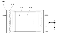
- FIG. 3 is a schematic diagram showing a first schematic configuration example of a mirror unit 300 of a comparative example
- FIG. 4 is a front view of the mirror unit 300 shown in FIG.
- the mirror unit 300 shown in FIGS. 3 and 4 is partially different in configuration from the mirror unit 300 shown in FIG. 360a and 360b are arranged, and a drive section 371 is arranged.
- portions of the mirror 310 and the holding portion 320 that are covered by the plate springs 360a and 360b are indicated by broken lines, and the axis 340 and the driving portion 371 arranged below the holding portion 320 in the H direction are indicated by the broken lines. It is indicated by another dashed line.
- the mirror 310 has a square prism shape.
- the mirror 310 includes a reflective surface 310a that reflects light transmitted through the prism and surfaces other than the reflective surface 310a.
- the reflecting surface 310a is the surface of the mirror 310, is along the VZ plane, and has a rectangular shape elongated in the Z direction on the VZ plane.
- the surfaces other than reflecting surface 310a include the side surface and the back surface of mirror 310 facing reflecting surface 310a.
- the side surface is an adjacent surface adjacent to the reflecting surface 310a, and the back surface is a surface facing the reflecting surface 310a.
- the holding portion 320 is a frame-shaped member having a bottom portion, and an opening is provided inside the peripheral wall, which is the frame of the holding portion 320, and the peripheral wall and the opening have a rectangular shape elongated in the Z direction on the VZ plane.
- the mirror 310 is placed on the bottom surface of the mirror 310 with the rear surface of the mirror 310 interposed therebetween.
- the peripheral wall of the holding portion 320 surrounds the side surface of the mirror 310 so that a gap is provided between the side surface of the mirror 310 and the inner peripheral surface of the peripheral wall of the holding portion 320 .
- the upper surface of the peripheral wall is positioned lower than the reflecting surface 310a.
- a V-groove is provided on the back surface of the bottom opposite to the surface on which the mirror 310 rests.
- An axis 340 is arranged in the V-groove, and the V-groove and the axis 340 are along the V-direction perpendicular to the HZ plane in which the light is wavelength-dispersed.
- the V-groove and shaft 340 are provided on the end side of the holding portion 320 in the Z direction.
- a shaft 340 shown in FIGS. 3 and 4 is a rod-shaped member.
- the main surfaces of the leaf springs 360a and 360b are rectangular and elongated in the V direction of the VZ plane.
- the plate springs 360a and 360b are arranged on both ends of the reflecting surface 310a in the Z direction, and press the mirror 310 against the bottom wall of the holder 320 to fix the mirror 310 to the holder 320. As shown in FIG.
- the driving portion 371 is arranged on the back surface of the bottom portion of the holding portion 320 , and the driving shaft of the driving portion 371 extends along the H direction and is fixed to the back surface of the bottom portion of the holding portion 320 .
- the driving portion 371 is arranged on the end side of the holding portion 320 on the side opposite to the shaft 340 in the Z direction. Further, the driving portion 371 is arranged substantially in the center of the holding portion 320 in the V direction.
- the drive unit 371 is, for example, a stepping motor.
- FIG. 5 is a schematic diagram showing a second schematic configuration example of the mirror unit 300 of the comparative example.
- 6 is a front view of the mirror unit 300 shown in FIG. 5.
- FIG. 6 the same reference numerals are assigned to the same configurations as those described above, and duplicate descriptions will be omitted unless otherwise specified.
- the adhesives 380a, 380b, 380c arranged below the mirror 310 in the H direction are indicated by dashed lines.
- a mirror unit 300 shown in FIGS. 5 and 6 is the mirror unit 300 shown in FIG. 2 and is a different mirror unit from the mirror unit 300 shown in FIG. In FIG. 2, adhesives 380a, 380b, and 380c are omitted for clarity.
- Adhesives 380a, 380b, and 380c are provided between the surface of the mirror 310 excluding the reflecting surface 310a and the holding portion 320, adhere the surface and the holding portion 320, and adhere the mirror 310 to the holding portion 320. .
- adhesives 380 a , 380 b , 380 c are provided in the VZ plane between the back surface of mirror 310 and the bottom surface of holder 320 to adhere mirror 310 to holder 320 .
- an epoxy resin can be used, and the adhesives 380a, 380b, 380c cure and shrink during adhesion.
- the heights of the adhesives 380a, 380b, 380c are approximately the same in the H direction.
- the adhesive 380a is provided on the opposite side to the adhesives 380b and 380c with respect to the axis 340, specifically with respect to a center line 341 parallel to the axis 340 and passing through the center of the mirror 310 as a reference.
- two adhesives may be used, three or more adhesives define the surface and fix the surface, so that the posture of the mirror 310 is stabilized.
- the reflective surface 310a may be distorted due to the difference in height of each adhesive. Therefore, it is preferable that there are three adhesives.
- the holding part 320 holds the mirror 310 via the adhesives 380a, 380b, 380c as described above. Moreover, the holding part 320 is placed on the surface of the rotating stage 330 and fixed to the rotating stage 330 by a fastening member (not shown). The mirror 310 can be exchanged with respect to the rotation stage 330 together with the holder 320 . Note that the rotating stage 330 may be integrated with the holding section 320 .
- a V-groove is provided on the back surface of the rotary stage 330, and a shaft 340 is arranged in the V-groove.
- the V-groove and axis 340 are along the V-direction.
- the shaft 340 shown in FIGS. 5 and 6 is a rod-shaped member, but it may be a virtual shaft without substance.
- the V-groove and axis 340 are provided approximately in the center of the mirror 310 and the rotary stage 330 in the Z direction, and pass through the center of the mirror 310 when the reflecting surface 310a is viewed from the front.
- Drive units 351 a and 351 b are arranged on the back surface of the rotation stage 330 .
- the drive units 351a and 351b are piezo elements.
- the drive units 351a and 351b are arranged symmetrically with respect to the center line 341. As shown in FIG.
- the drive units 351a and 351b are arranged substantially in the center of the rotary stage 330 in the V direction.
- the internal spaces of the optical path tubes 68a, 70a, 161a and the internal spaces of the housings 68, 151a are filled with a purge gas from a purge gas supply source (not shown).
- a laser gas is supplied to the internal space of the housing 30 from a laser gas supply device (not shown).
- the processor 190 sets a predetermined charging voltage in the charger and turns on the switch. Thereby, the pulse power module generates a pulsed high voltage from the electrical energy held in the charger, and the high voltage is applied between the electrodes 32a and 32b. When a high voltage is applied, the insulation between the electrodes 32a and 32b is broken and discharge occurs. When a discharge occurs, the laser medium contained in the laser gas between the electrodes 32a and 32b is excited by the energy of this discharge, and emits spontaneous emission light when returning to the ground state. Part of this light is ultraviolet rays and passes through the window 31b.
- the width is expanded in the direction in which the light travels, and the wavelength is dispersed.
- Light from prism 63 is reflected by mirror 310 toward prism 64 and guided to grating 66 via prism 64 .
- the light reflected by the grating 66 propagates through the prisms 61 , 62 , 63 , 64 and the mirror 310 to the inner space of the housing 30 from the window 31 b again.
- Light propagating in the internal space of the housing 30 has a narrow band. This narrowed-band light causes stimulated emission in the laser medium in an excited state, and the light is amplified.
- the light travels through window 31 a to output coupling mirror 70 . Part of the light is transmitted through the output coupling mirror 70, and the remaining part of the light is reflected by the output coupling mirror 70, transmitted through the window 31a, and propagates into the internal space of the housing 30.
- the light propagated into the internal space of the housing 30 travels to the grating 66 via the window 31b, prisms 61, 62, 63, 64 and mirror 310 as described above.
- light of a given wavelength travels back and forth between grating 66 and output coupling mirror 70 .
- the light is amplified each time it passes through the discharge space in the internal space of the housing 30, causing laser oscillation.
- a portion of the laser light passes through the output coupling mirror 70 as pulsed laser light and travels to the beam splitter 151b.
- the windows 31a and 31b are inclined at Brewster's angle with respect to the traveling direction of the laser light so as to suppress the reflection of the P-polarized light of the laser light.
- reflection of the P-polarized laser light traveling toward these side surfaces from the outside of the respective prisms 61, 62, 63, and 64 is suppressed on the side surfaces of the prisms 61, 62, 63, and 64. As such, a film is deposited. Therefore, the pulsed laser light traveling to the beam splitter 151b has a narrow band, and the polarization component in the H direction is increased.
- a part of the pulsed laser light traveling to the beam splitter 151b is reflected by the beam splitter 151b.
- the reflected pulsed laser beam is received by the optical sensor 151c, and the optical sensor 151c measures the pulse energy of the received pulsed laser beam.
- Optical sensor 151c outputs a signal to processor 190 indicating the pulse energy to be measured.
- the processor 190 also receives a signal from the exposure device 200 that indicates the wavelength of the light to be emitted by the gas laser device 100 .
- the processor 190 controls the prism drive section and the drive sections 351a and 351b based on signals from the optical sensor 151c and the exposure apparatus 200 to rotate the rotation stages 63a and 330.
- the driving sections 351 a and 351 b rotate the holding section 320 via the rotating stage 330 so that the mirror 310 rotates around the axis 340 .
- the rotary stage 330 is pushed and pulled by the driving portions 351a and 351b, and rotates about the shaft 340 together with the holding portion 320.
- the rotation angles of the rotation stages 63a and 330 are, for example, within a range of approximately ⁇ 2.5 degrees.
- the orientations of the prism 63 and the mirror 310 change as the rotary stages 63a and 330 rotate.
- the drive units 351a and 351b drive in opposite directions, so that the rotation stage 330 is pushed and pulled by the drive units 351a and 351b. It rotates about the axis together with the holding part 320 .
- the processor 190 adjusts the rotation angles of the prism 63 and the mirror 310 based on the signals from the optical sensor 151c and the exposure apparatus 200 so that the difference between the pulse energy and the target pulse energy is within the allowable range. Feedback control of the charging voltage of the charger.
- the beam passes through the beam splitter 151b and the exit window 161 and enters the exposure apparatus 200.
- This pulsed laser light is ArF laser light, which is ultraviolet light with a center wavelength of 193.4 nm.
- the gas laser device 100 of this example performs dual-wavelength oscillation in which the oscillation wavelength of the pulsed laser light emitted from the gas laser device 100 toward the exposure device 200 is repeatedly switched to two wavelengths every one to several pulses.
- two wavelengths are switched by adjusting the rotation angle of the mirror 310 to change the angle of incidence on the grating 66 .
- the two-wavelength oscillation irradiates the workpiece with two pulsed laser beams having different focal depths.
- the focal depths of the two pulsed laser beams are shifted between shallow and deep portions of the work piece, compared to single-wavelength oscillation with the same focal depth.
- the mirror 310 When the gas laser device 100 oscillates with two wavelengths, the mirror 310 needs to rotate at high speed in order to repeatedly switch the oscillation wavelength to two wavelengths.
- the rotational speed of the mirror 310 rotated by the stepping motor is the speed required for the two-wavelength oscillation. sometimes slower than If the rotation speed is slow, the gas laser device 100 may not be able to oscillate with two wavelengths. Therefore, in the drive unit 371, a piezo element is used instead of a stepping motor, and the piezo element rotates the mirror 310 at a speed required for the two-wavelength oscillation.
- the mirror unit 300 shown in FIGS. 5 and 6 is used in which adhesives 380a, 380b, 380c are provided instead of leaf springs 360a, 360b.
- the adhesives 380a, 380b, and 380c pull the mirror 310 toward the rotation stage 330 in the H direction perpendicular to the reflecting surface 310a due to their curing shrinkage during adhesion.
- the tensile force of the adhesives 380a, 380b, and 380c may be applied to the mirror 310 and propagated through the mirror 310 to the reflecting surface 310a.
- the reflective surface 310a may become distorted.
- the adhesives 380a, 380b, and 380c adhere to the rear surface of the mirror 310 and the bottom surface of the holder 320, the stability of the mirror 310 increases, but the distortion increases.
- the amount of adhesives 380a, 380b, and 380c can be reduced.
- the adhesive strength of each decreases.
- the load applied to the adhesives 380a, 380b, and 380c during rotation of the mirror 310 may cause the mirror 310 to separate from the adhesives 380a, 380b, and 380c.
- the holding part 320 may be deformed by the fastening force of the fastening member. In this deformation, the holding portion 320 may warp around the fastening member.
- the stress generated by the deformation may propagate to the adhesives 380a, 380b, and 380c.
- the stress may propagate from the adhesives 380a, 380b, and 380c to the reflecting surface 310a via the mirror 310, resulting in distortion of the reflecting surface 310a. Due to the distortion of the reflecting surface 310a and the peeling off of the mirror 310 as described above, the gas laser device 100 does not emit a pulsed laser beam that satisfies the performance required by the exposure device 200, and there is concern that the reliability of the gas laser device 100 is lowered. occurs.
- a band narrowing module 60 capable of suppressing deterioration in reliability of the gas laser device 100 is exemplified.
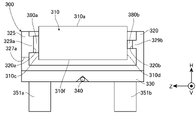
- FIG. 7 is a schematic diagram showing a schematic configuration example of the mirror unit 300 of this embodiment.
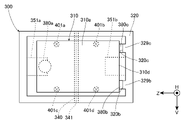
- 8 is a front view of the mirror unit 300 shown in FIG. 7.
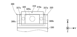
- FIG. 9 is a side view of the mirror unit 300 viewed from the plate member 325 side.
- the mirror unit 300 of this embodiment is different from the mirror unit 300 shown in FIGS.
- the plate member 325 is used as an example of the member, but a wall member or the like may be used.
- the adhesive 380a adheres to the side surface of the mirror 310 and the plate member 325 included in the peripheral wall of the holding portion 320
- the adhesives 380b and 380c adhere to the side surface of the mirror 310 and the inner peripheral surface of the peripheral wall of the holding portion 320. It is different from the mirror unit 300 shown in FIGS. 5 and 6 in that it is adhered to the .
- the plate member 325 is arranged in a notch portion 327 a provided in the peripheral wall of the holding portion 320 .
- the notch 327a is provided in one of the wall portions along the HV plane of the peripheral wall, penetrates the peripheral wall in the Z direction, and is longer than the mirror 310 in the V direction.
- the plate member 325 is shorter than the notch 327a and the mirror 310 in the V direction.
- the plate member 325 has a square prism shape and is made of the same material as the holding portion 320 .
- a side surface of the plate member 325 along the HV plane faces one side surface of the mirror 310 along the HV plane.
- the plate member 325 is arranged on the holding portion 320 in a state where the adhesive 380a adheres to a later-described pedestal 329a of the plate member 325.
- the plate member 325 is a wall to which the adhesive 380a adheres, and the plate member 325 is provided with a pair of through holes 325a.
- the through hole 325a is longer in the Z direction than in the V direction, and penetrates the plate member 325 in the H direction.
- the plate member 325 is fixed to the holding portion 320 by adjusting the position in the thickness direction of the adhesive 380a by fastening the fastening member 325b, which is a screw, to the holding portion 320 through the through hole 325a.
- the thickness direction is the Z direction connecting the mirror 310, the adhesive 380a, and the plate member 325 of the holding portion 320, and is the direction orthogonal to the axis 340 when the reflecting surface 310a is viewed from the front.
- the thickness direction is the direction perpendicular to the axis perpendicular to the reflecting surface 310a and the center line 341, and is the direction connecting the adhesive surface between the plate member 325 and the adhesive 380a and the adhesive surface between the mirror 310 and the adhesive 380a. is.
- the method of fixing the plate member 325 is not limited to the above, and the plate member 325 may be fixed to the holding portion 320 by adhesion.
- the plate member 325 is provided with a pedestal 329a.
- Pedestals 329 b and 329 c are also provided on the inner peripheral surface of the peripheral wall of the holding portion 320 .
- the pedestals 329b and 329c are provided on the opposite side of the center line 341 from the pedestal 329a.
- the holding portion 320 includes holding surfaces 320 a , 320 b , 320 c to which adhesives 380 a , 380 b , 380 c adhere to hold the mirror 310 .
- the holding surfaces 320a, 320b, 320c are surfaces different from each other.
- the holding surface 320a is a surface of the pedestal 329a to which the adhesive 380a, which is the first adhesive, adheres.
- the holding surface 320b is a surface of the pedestal 329b to which the adhesive 380b, which is the second adhesive, adheres.
- the holding surface 320c is a surface of the pedestal 329c to which the adhesive 380c, which is the third adhesive, adheres.
- the holding surfaces 320a, 320b, and 320c of this embodiment intersect the VZ plane along the in-plane direction of the reflecting surface 310a and are along the HV plane.
- the holding surface 320a is provided on the opposite side of the center line 341 from the holding surfaces 320b and 320c.
- the holding surfaces 320a, 320b, and 320c are circular, but the shape is not particularly limited.
- the shaft 340 is a rod-shaped member, but may be a virtual shaft without substance.
- Axis 340 also includes a line perpendicular to the HZ plane along which light exiting prism 63 is wavelength-dispersed.
- the adhesive 380 a adheres to the holding surface 320 a of the pedestal 329 a and the side surface of the mirror 310 facing the holding surface 320 a to adhere the mirror 310 to the plate member 325 .
- the adhesive 380 b adheres to the holding surface 320 b of the pedestal 329 b and the side surface of the mirror 310 facing the holding surface 320 b to adhere the mirror 310 to the holding portion 320 .
- the adhesive 380 c adheres to the holding surface 320 c of the base 329 c and the side surface of the mirror 310 facing the holding surface 320 c to adhere the mirror 310 to the holding portion 320 .
- the adhesives 380b and 380c are located on the opposite side of the adhesive 380a with respect to the axis 340, specifically the center line 341, when the reflective surface 310a is viewed from the front.
- a front view indicates viewing the reflecting surface 310a along the H direction perpendicular to the reflecting surface 310a.
- the center of the mirror 310 of this embodiment is the intersection of the diagonal lines of the reflecting surface 310a when the reflecting surface 310a is viewed from the front.
- the side surface of the mirror 310 to which the adhesive 380a adheres is different from the side surface of the mirror 310 to which the adhesives 380b and 380c adhere and faces the side surface.
- the side surface of the mirror 310 to which the adhesive 380a adheres is the first adjacent surface 310c adjacent to the reflecting surface 310a
- the side surface of the mirror 310 to which the adhesives 380b and 380c adhere is the reflecting surface 310a.
- the first adjacent surface 310c of this embodiment faces the second adjacent surface 310d.
- the adhesive 380b and the pedestal 329b are located in the same HV plane as the adhesive 380c and the pedestal 329c, but are offset in the V direction. Therefore, the adhesive 380b is provided at a position different from the adhesive 380c on the second adjacent surface 310d.
- mirror 310 is held in one place on the left side of axis 340 by adhesive 380a and in two places on the right side of axis 340 by adhesives 380b and 380c.
- the adhesives 380a, 380b, 380c and the pedestals 329a, 329b, 329c are located closer to the reflective surface 310a than the bottom surface of the holding part 320 in the H direction perpendicular to the reflective surface 310a.
- the mirror 310 is held by the holding portion 320 with the adhesives 380a, 380b, and 380c in a state in which the back surface 310f, which is the opposite surface facing the reflecting surface 310a, is separated from the bottom surface of the holding portion 320.
- the respective centers of the adhesives 380a, 380b, 380c and the pedestals 329a, 329b, 329c are positioned at approximately the same height in the H direction perpendicular to the reflecting surface 310a. In the Z direction, the adhesives 380a, 380b, 380c and the pedestals 329a, 329b, 329c have approximately the same length.
- Pedestal 329a is provided such that adhesive 380a adheres approximately to the center of mirror 310 in the V direction.
- Pedestals 329b and 329c are provided so that adhesives 380b and 380c adhere to both end sides of mirror 310 in the V direction.
- the adhesive 380a and the pedestal 329a are positioned above the driving portion 351a, and the adhesives 380b and 380c and the pedestals 329b and 329c are positioned above the driving portion 351b.
- the upper side is the reflecting surface 310a side.
- the adhesive 380a and the base 329a are arranged above the driving portion 351a, and the driving portion 351b is arranged between the adhesive 380b and the base 329b and the adhesive 380c and the base 329c.
- the adhesive 380b and the pedestal 329b are provided on the side opposite to the adhesive 380c and the pedestal 329c with respect to the driving portion 351b. Further, the adhesive 380b and the base 329b and the adhesive 380c and the base 329c are provided symmetrically with respect to the driving portion 351b.
- the area of the holding surface 320a on the pedestal 329a is approximately the same as the sum of the area of the holding surface 320b on the pedestal 329b and the area of the holding surface 320c on the pedestal 329c. Further, the area of the holding surface 320a is approximately twice the area of each of the holding surfaces 320b and 320c.
- Each of the adhesives 380a, 380b, 380c adheres entirely to each of the holding surfaces 320a, 320b, 320c.
- the area of the bonding surface between the holding surface 320a and the adhesive 380a is approximately the same as the sum of the area of the bonding surface between the holding surface 320a and the adhesive 380b and the area of the bonding surface between the holding surface 320a and the adhesive 380c. be. Further, the area of the bonding surface between the holding surface 320a and the adhesive 380a is approximately 2 of the area of the bonding surface between the holding surface 320a and the adhesive 380b and the area of the bonding surface between the holding surface 320a and the adhesive 380c. Double.
- the mirror unit 300 further includes fastening members 401 a, 401 b, 401 c, and 401 d that fix the rotating stage 330 to the holding portion 320 . Since the fastening members 401a, 401b, 401c, and 401d are arranged below the mirror 310 in the bottom portion of the holding portion 320, they are indicated by dashed lines in FIG. The longitudinal direction of the fastening members 401a, 401b, 401c, 401d extends in the H direction. The fastening members 401a, 401b, 401c, and 401d are arranged so as to be positioned at the vertices of the quadrangle.
- the fastening member 401a is disposed on the opposite side of the fastening member 401b with respect to the center line 341, and the fastening member 401c is disposed on the opposite side of the fastening member 401d with respect to the center line 341.
- the fastening member 401a is arranged on the opposite side of the fastening member 401c with respect to the HZ plane
- the fastening member 401b is arranged on the opposite side of the fastening member 401d with respect to the HZ plane.
- the number and positions of fastening members are not limited to the above.
- the adhesive 380 a that is the first adhesive is provided between the first adjacent surface 310 c that is the side surface of the mirror 310 and the holding portion 320 .
- Adhesive 380 b that is the second adhesive is provided between second adjacent surface 310 d that is the side surface of mirror 310 and holding portion 320 .
- the adhesive 380 a and the adhesive 380 b adhere the mirror 310 to the holding portion 320 .
- the tensile force of the adhesive 380b is applied to the mirror 310 in the in-plane direction.
- the adhesive 380b adheres to the back surface 310f and the bottom surface of the retainer 320, and the tensile force propagates to the reflective surface 310a compared to when the tensile force is applied to the mirror 310 in the H direction perpendicular to the reflective surface 310a. can be reduced. Reducing the tensile force may reduce distortion of the reflective surface 310a.
- the distortion of the reflective surface 310a since the distortion of the reflective surface 310a is suppressed, it may not be necessary to reduce the amount of the adhesives 380a and 380b in order to suppress the distortion of the reflective surface 310a. It is possible to suppress the decrease in each adhesive force due to. When the decrease in adhesive force is suppressed, the resistance to the load applied to the adhesives 380a and 380b during the rotation of the mirror 310 can be improved compared to the case where the adhesive force is decreased, and peeling of the mirror 310 can be suppressed. . As described above, when the distortion of the reflecting surface 310 a and the peeling of the mirror 310 are suppressed, the gas laser device 100 can emit pulsed laser light that satisfies the performance required by the exposure device 200 . Therefore, deterioration in reliability of the gas laser device 100 can be suppressed.
- the adhesive 380b is located on the opposite side of the adhesive 380a with respect to a center line 341 parallel to the axis 340 and passing through the center of the mirror 310 when the reflecting surface 310a is viewed from the front.
- the adhesives 380a and 380b are less likely to be removed from the adhesives 380a and 380b than if the adhesives 380a and 380b were provided on the same side of the center line 341. Peeling of the mirror 310 can be suppressed.
- the holding part 320 may be deformed by the fastening force of the fastening members 401a, 401b, 401c, 401d.
- the holding portion 320 may warp around the fastening members 401a, 401b, 401c, and 401d.
- the stress may propagate from the adhesives 380a, 380b, and 380c to the reflecting surface 310a via the mirror 310, and the reflecting surface 310a may be distorted.
- the adhesive 380b of this embodiment adheres to the holding surface 320b and the side surface of the mirror 310 .
- the stress caused by the deformation is applied to the reflecting surface 310a through the adhesive 380b and the mirror 310, compared to the case where the adhesive 380b adheres to the back surface 310f and the holding portion 320. can be difficult to propagate to When the stress becomes difficult to propagate, the distortion of the reflective surface 310a can be suppressed.
- the number of the fastening members 401a, 401b, 401c, and 401d can be reduced.
- the distortion of the reflecting surface 310a due to the fastening force is suppressed by the adhesive 380b.
- the first adjacent surface 310c faces the second adjacent surface 310d. Therefore, the adhesives 380a and 380b are provided on both sides of the mirror 310 in the Z direction, and the mirror 310 is held by the holders 320 from both sides. In this case, peeling of mirror 310 can be suppressed compared to the case where adhesives 380 a and 380 b are not provided on both sides of mirror 310 .
- the band narrowing module 60 of the present embodiment is provided between the second adjacent surface 310d, which is the side surface of the mirror 310 to which the adhesive 380b is adhered, and the holding portion 320, and the mirror 310 is adhered to the holding portion 320.
- It further comprises an adhesive 380c, which is a third adhesive.
- peeling of the mirror 310 can be suppressed compared to the case where the adhesive 380c is not provided.
- the adhesive 380c does not necessarily have to be provided. If adhesive 380c is not provided, adhesive 380a is preferably provided symmetrically with adhesive 380b with respect to center line 341. FIG.
- the adhesives 380a, 380b, and 380c are positioned at the same height position in the H direction perpendicular to the reflecting surface 310a. In this case, peeling of the mirror 310 can be suppressed compared to the case where the adhesives 380a, 380b, and 380c are not positioned at the same height position in the H direction. Note that the adhesives 380a, 380b, and 380c do not have to be positioned at the same height position in the H direction.
- the area of the bonding surface between the base 329a and the adhesive 380a is approximately the same as the sum of the area of the bonding surface between the base 329b and the adhesive 380b and the area of the bonding surface between the base 329c and the adhesive 380c.
- the area on the side of adhesive 380a may not be substantially the same as the sum of the areas of the adhesives 380b and 380c. Also, the area on the side of the adhesive 380a may not be approximately twice the area on the sides of the adhesives 380b and 380c.
- the adhesives 380a, 380b, 380c adhere to the holding surfaces 320a, 320b, 320c of the pedestals 329a, 329b, 329c.
- Spreading of the adhesive 380a from the holding surface 320a can be restrained by the edge of the holding surface 320a and the surface tension of the adhesive 380a. Therefore, the area of the bonding surface between the holding surface 320a and the adhesive 380a can be approximately the same as the area of the holding surface 320a.
- by suppressing spreading as described above spreading of the adhesive 380a on the first adjacent surface 310c can be suppressed.
- the area of the bonding surface between the mirror 310 and the adhesive 380a can be approximately the same as the area of the bonding surface between the holding surface 320a and the adhesive 380a. Therefore, the area of the bonding surface between the pedestal 329a side and the mirror 310 side of the adhesive 380a can be adjusted by the holding surface 320a.
- the adhesive 380a has been described above, the same applies to the adhesives 380b and 380c. As a result, the area of the bonding surface between the mirror 310 and the adhesive 380a is approximately the same as the sum of the area of the bonding surface between the mirror 310 and the adhesive 380b and the area of the bonding surface between the mirror 310 and the adhesive 380c. .
- the area on the adhesive 380a side is not substantially the same as the sum of the areas on the adhesives 380b and 380c side, variations in the loads applied to the adhesives 380a and 380b and 380c can be suppressed. . Suppressing variations can suppress variations in deterioration of the adhesives 380a, 380b, and 380c. Also, the area of the bonding surface between the mirror 310 and the adhesive 380a is approximately twice the area of the bonding surface between the mirror 310 and the adhesive 380b and the area of the bonding surface between the mirror 310 and the adhesive 380c. .
- the plate member 325 is fixed to the holding portion 320 after adjusting the position in the Z direction, which is the thickness direction of the adhesive 380a. Therefore, the plate member 325 can absorb the dimensional tolerance of the mirror 310 and the processing tolerance of the holding portion 320 in the Z direction. When the plate member 325 absorbs the dimensional tolerance and processing tolerance, deformation of the adhesives 380a, 380b, 380c due to the dimensional tolerance and processing tolerance can be suppressed. Thereby, displacement of the mirror 310 can be suppressed.
- the plate member 325 absorbs the dimensional tolerance and processing tolerance, the change in the length of the adhesives 380a, 380b, and 380c in the Z direction due to the dimensional tolerance and processing tolerance is suppressed, and the change in adhesive force due to the length change is suppressed. can be suppressed.
- the plate member 325 of this embodiment is provided on the adhesive 380a side, it may be provided on the adhesives 380b and 380c side. In this case, one plate member 325 may be provided for the adhesives 380b and 380c, or may be provided for each of the adhesives 380b and 380c. Therefore, the plate member 325 may be fixed to the holding portion 320 by adjusting the position in the thickness direction of one of the adhesives 380a, 380b, and 380c. Also, the spread of the adhesive 380a that adheres to the plate member 325 and the mirror 310 may be adjusted by, for example, a frame member (not shown) other than the pedestal 329a.
- the adhesive 380a is provided inside the frame member and hardened, thereby adjusting the area of the adhesive surface between the holding portion 320 and the adhesive 380a. If a frame member is used, the pedestal 329a may not be required.
- the method for adjusting the area of the bonding surface is not particularly limited. Although the adjustment of the area of the bonding surface has been described using the adhesive 380a, the same applies to the adhesives 380b and 380c.
- the pedestal 329a is integrated with the plate member 325, but may be separate. Also, the pedestals 329b and 329c are integrated with the peripheral wall, but may be separate. Pedestals 329 a , 329 b , 329 c may be provided on mirror 310 .
- the positions of the adhesives 380a, 380b, 380c and the pedestals 329a, 329b, 329c are particularly limited. not.
- the shape of the mirror 310 may be any columnar shape.
- the adhesives 380a, 380b, and 380c are provided on the HV plane, but are not limited to this.
- Other examples of arrangement positions of the adhesives 380a, 380b, and 380c will be described using Modified Examples 1 and 2 below.
- FIG. 10 is a front view of the mirror unit 300 in Modification 1 of Embodiment 1.
- the plate member 325 and the notch portion 327a are provided on one of the wall portions along the HZ plane of the peripheral wall of the holding portion 320, unlike the mirror unit 300 of the first embodiment. is different.
- the third adjacent surface 310e which is the side surface to which the adhesive 380c of the mirror 310 adheres, faces the second adjacent surface 310d, which is the side surface to which the adhesive 380b adheres.
- the third adjacent surface 310e is a surface adjacent to the reflecting surface 310a.
- the mirror unit 300 of this modified example differs from the mirror unit 300 of the first embodiment in that the adhesive 380b adheres to the plate member 325 and the mirror 310 .
- the plate member 325 and the notch 327a are provided on the end side of the mirror 310 opposite to the adhesive 380a in the Z direction.
- the notch 327a penetrates the peripheral wall in the V direction.
- the notch 327a is shorter than the mirror 310 in the Z direction together with the plate member 325.
- a pedestal 329b is provided on the plate member 325, and a holding surface 320b of the pedestal 329b extends along the HZ plane.
- the pedestal 329c is provided on the opposite side of the pedestal 329b with respect to the mirror 310, and the holding surface 320c of the pedestal 329c extends along the HZ plane.
- the adhesive 380b is provided on the opposite side of the mirror 310 from the adhesive 380c.
- the adhesives 380b and 380c are provided symmetrically with respect to the mirror 310. As shown in FIG. The plate member 325 and the notch 327a and the base 329c may be positioned opposite to each other, and the base 329b of the plate member 325 may be adhered with the adhesive 380c.
- the holding part 320 further includes a notch 327b through which the mirror 310 passes because the mirror 310 is arranged inside the peripheral wall.
- the notch portion 327b is provided on the wall portion of the peripheral wall of the holding portion 320 along the HV plane, which is opposite to the wall portion to which the adhesive 380a adheres with respect to the center line 341 .
- the notch 327b penetrates the peripheral wall in the Z direction and is longer than the mirror 310 in the V direction.
- the peripheral wall of the holding portion 320 is provided at that position instead of the plate member 325 and the notch portion 327a.
- a pedestal 329a is provided on the peripheral wall, and a holding surface 320a is provided on the pedestal 329a.
- the adhesive 380a adheres to the holding surface 320a and is located on the opposite side of the center line 341 from the adhesives 380b and 380c.
- the bonding surface between the mirror 310 and the adhesive 380a is along the HV plane, and the respective bonding surfaces between the mirror 310 and the adhesives 380b and 380c are along the HZ plane.
- a first normal 391a on the bonding surface between mirror 310 and adhesive 380a intersects a second normal 391b on the bonding surface between mirror 310 and adhesive 380b inside mirror 310 .
- the first normal 391a further intersects the third normal 391c at the bonding surface between the mirror 310 and the adhesive 380c inside the mirror 310 .
- the first normal 391a intersects the third normal 391c at an intersection 391e between the first normal 391a and the second normal 391b.
- the intersection point 391e is located on the opposite side of the center line 341 from the adhesive 380a.
- the adhesive 380a pulls the mirror 310 in the Z direction as in the first embodiment.
- the side surface of the mirror 310 to which the adhesive 380c adheres faces the side surface to which the adhesive 380b adheres. Shear in the Z direction. Therefore, the thickness direction of the adhesives 380b and 380c is the V direction, the shearing direction of the adhesives 380b and 380c is the Z direction, and a combined oblique force between the V and Z directions is applied to the mirror 310.
- FIG. In this case, the rigidity of the entire mirror unit 300 can be improved compared to the case where the combined force is not applied to the mirror 310 .
- the first normal line 391 a intersects the second normal line 391 b inside the mirror 310 .
- the rigidity of the mirror unit 300 as a whole can be improved, and the rotational responsiveness of the mirror 310 can be improved.
- the first normal 391a intersects the third normal 391c at the intersection 391e between the first normal 391a and the second normal 391b.
- the rigidity of the mirror unit 300 as a whole can be improved, and the rotational responsiveness of the mirror 310 can be improved.
- FIG. 11 is a schematic diagram showing a schematic configuration example of the mirror unit 300 of Modification 2 of Embodiment 1.
- FIG. 12 is a front view of the mirror unit 300 shown in FIG. 11.
- an adhesive 380a is provided between the back surface 310f and the bottom surface of the holding portion 320 facing the back surface 310f, similarly to the comparative example, to adhere the mirror 310 to the holding portion 320. It differs from the mirror unit 300 of the first embodiment in this point. Further, the mirror unit 300 of this modified example differs from the mirror unit 300 of the first embodiment in that the plate member 325 and the notch portion 327a are not provided.
- FIG. 11 is a schematic diagram showing a schematic configuration example of the mirror unit 300 of Modification 2 of Embodiment 1.
- FIG. 12 is a front view of the mirror unit 300 shown in FIG. 11.
- an adhesive 380a is provided between the back surface 310f and the bottom surface of the holding portion 320 facing the back surface 310f, similarly to the comparative example, to adhere the
- the adhesive 380a arranged below the mirror 310 is indicated by a dashed line.
- Adhesives 380b and 380c are provided in the same manner as in the first embodiment. Therefore, the mirror 310 is held by the back surface 310f and the second adjacent surface 310d, which is the side surface.
- the pedestal 329a is provided on the surface of the bottom portion of the holding portion 320 .
- a holding surface 320a of the base 329a extends along the VZ plane. Therefore, the bonding surface of the adhesive 380a to the mirror 310 and holding surface 320a is along the VZ plane.
- the pedestal 329a and the adhesive 380a are provided approximately in the center of the mirror 310 in the V direction.
- the adhesive 380a adheres to the back surface 310f and the holding surface 320a of the pedestal 329a at the bottom of the holding portion 320 facing the back surface 310f.
- Adhesives 380b and 380c are provided in the same manner as in the first embodiment, and adhere to the second adjacent surface 310d, which is the side surface of the mirror 310, and the holding surfaces 320b and 320c of the holding portion 320 facing the side surface. Accordingly, the adhesive surface of the adhesive 380a to the mirror 310 and the holding surface 320a is along the VZ plane, and the adhesive surfaces of the adhesives 380b and 380c to the mirror 310 and the holding surface 320a are along the HV plane.
- the rigidity of the mirror unit 300 as a whole can be improved compared to the case where the respective shearing directions are not perpendicular.
- the distortion of the reflecting surface 310a is suppressed by the adhesives 380b and 380c compared to the case where all the adhesives 380a, 380b, and 380c are adhered to the back surface 310f and the bottom surface of the holding portion 320 as in the comparative example.
- the adhesive 380a eliminates the need for the plate member 325 to absorb the dimensional tolerance of the mirror 310 and the processing tolerance of the holding portion 320, the plate member 325 may be unnecessary, and the processing of the cutout portion 327a in the holding portion 320 is not required. can be unnecessary. Note that even if the mirror 310 is tilted due to curing shrinkage of the adhesive 380a, the tilt is allowed by rotation control of the rotation stage 330 by the drive units 351a and 351b.
- the first normal 391a of the adhesive 380a when viewed from the direction V, is three-dimensionally aligned with the second normal 391b of the adhesive 380b in the mirror 310. cross. Although not shown, the first normal 391a three-dimensionally intersects the third normal 391c of the adhesive 380c within the mirror 310 as well. In such a case, the rigidity of the mirror unit 300 as a whole can be improved compared to the case where the respective normal lines of the adhesives 380a, 380b, and 380c do not three-dimensionally intersect.
- the rigidity of the mirror unit 300 as a whole can be improved compared to the case where the mirror 310 is fixed only on the HV plane. Therefore, the natural frequency of mirror 310 may be improved.
- FIG. 13 is a front view of the mirror unit 300 according to this embodiment.
- the shape of the mirror 310 is different from the shape of the mirror 310 of the first embodiment.
- Adjacent surfaces 310d and 310e which are the side surfaces to which the adhesives 380b and 380c of the mirror 310 of this embodiment adhere, are chamfered.
- Chamfering is, for example, C-chamfering.
- the normals 391b and 391c are inclined toward the axis 340 due to the chamfering compared to the case where the chamfering is not performed. 391f.
- the intersection point 391e is closer to the shaft 340 than when chamfering is not performed.
- the intersection 391e is positioned between the axis 340 and the line 391f on the VZ plane.
- the rigidity of the mirror unit 300 as a whole can be improved and the responsiveness of the rotation of the mirror 310 can be improved as compared with the case where the intersection point 391e is positioned on the line 391f.
- FIG. 14 is a front view of the mirror unit 300 in Modification 1 of Embodiment 2.
- FIG. 14 the intersection point 391e may overlap the axis 340 when the reflective surface 310a is viewed from the front.
- the rigidity of the mirror unit 300 as a whole can be improved and the rotational responsiveness of the mirror 310 can be improved compared to the case where the intersection 391e is located between the axis 340 and the line 391f.
- FIG. 15 is a front view of a mirror unit 300 in Modification 2 of Embodiment 2.
- the mirror 310 has a cylindrical shape, and the adhesives 380a, 380b, and 380c adhere to the same side of the mirror 310 at different positions.
- intersection point 391e can easily overlap axis 340 when reflecting surface 310a is viewed from the front, compared to when mirror 310 does not have a cylindrical shape. Note that the intersection 391e may be positioned between the shaft 340 and the adhesive 380a when the reflecting surface 310a is viewed from the front.
- FIG. 16 is a front view of the mirror unit 300 in this embodiment.
- the mirror 310 is indicated by dotted lines
- the fastening members 401a, 401b, 401c, and 401d are indicated by solid lines
- the drive units 351a and 351b are omitted.
- the mirror unit 300 of the present embodiment differs from the holding section 320 of the first embodiment in that the holding section 320 further includes slits 403a, 403b, 403c, 403d, and 403e.
- the slits 403a, 403b, 403c, and 403d have the same size and are L-shaped, and the slit 403e has a rectangular shape elongated in the Z direction.
- Each of the slits 403 a , 403 b , 403 c , 403 d surrounds portions of fastening members 401 a , 401 b , 401 c , 401 d that fasten the holding part 320 to the rotation stage 330 .
- the slit 403a is provided between the fastening member 401a and the adhesive 380a, and the slit 403b is provided between the fastening member 401b and the adhesive 380c.
- the slit 403c is provided between the fastening member 401c and the adhesive 380a, and the slit 403d is provided between the fastening member 401d and the adhesive 380b.
- the slit 403a is located on the opposite side of the slit 403b with respect to the center line 341, and the slit 403c is located on the opposite side of the slit 403d with respect to the center line 341.
- the slit 403a is located on the opposite side of the slit 403c with respect to the HZ plane, and the slit 403b is located on the opposite side of the slit 403d with respect to the HZ plane. Also, the slit 403e is positioned between the slits 403a, 403b and the slits 403c, 403d.
- the slits 403a, 403b, 403c, 403d, and 403e reduce the stress generated in the holding portion 320 in the H direction by the fastening forces of the fastening members 401a, 401b, 401c, and 401d. can be reduced.
- the stress is reduced, deformation of the holding portion 320 due to the stress can be suppressed.
- the slits 403a, 403b, 403c, 403d, and 403e can suppress propagation of the stress to the adhesives 380a, 380b, and 380c, and can suppress deformation of the adhesives 380a, 380b, and 380c. Therefore, distortion of the reflecting surface 310a can be suppressed.
- At least one of the slits 403a, 403b, 403c, and 403d may be provided.
- FIG. 17 is a front view of a mirror unit 300 in a modified example of this embodiment.
- the slits 403a, 403b, 403c, and 403d are of the same size and have a rectangular shape elongated in the V direction, and the slit 403e has a triangular shape.
- One of the three vertices of the slit 403e is provided toward the adhesive 380a side, and the remaining two vertices are provided toward the adhesives 380b and 380c.
- the holding portion 320 is further provided with a rectangular slit 403f elongated in the V direction.
- the slit 403f is longer than the slit 403a and is provided on the opposite side of the center line 341 from the slit 403e.
- One end of the slit 403f is positioned between the slits 403a and 403b, and the other end of the slit 403f is positioned between the slits 403c and 403d.
- the slit 403f may be connected with the slit 403e.
- FIG. 18 is an enlarged view of the periphery of the adhesive 380a of the fourth embodiment.
- the mirror 310 includes a base material 311, a reflective film 313 that reflects part of the light transmitted through the prism 63 toward the grating 66, and a light shielding film that blocks light that passes through the reflective film 313 and advances to the adhesive 380a. 315 and , as main components.
- the reflective film 313 includes a reflective surface 310a. Although illustration of the adhesives 380b and 380c is omitted in FIG. 18, the light shielding film 315 also blocks light that passes through the reflective film 313 and advances to the adhesives 380b and 380c.
- the base material 311 includes, for example, glass, and adhesives 380a, 380b, and 380c adhere to the side surfaces of the base material 311.
- the light shielding film 315 is made of aluminum, for example, and is deposited on the surface of the base material 311 by vapor deposition. Since the reflective film 313 is laminated on the light shielding film 315 , the light shielding film 315 is provided between the base material 311 and the reflective film 313 .
- the reflective film 313 is provided on the side opposite to the base material 311 with respect to the light shielding film 315 .
- the reflective film 313 is a laminated film in which silicon layers and molybdenum layers are alternately laminated. The outermost layer of the reflective film 313 is a silicon layer. A film other than the silicon layer and the molybdenum layer may be used for the reflective film 313, and for example, a single layer film of ruthenium may be provided.
- the light shielding film 315 blocks the light passing through the reflecting film 313, so that the light traveling to the adhesives 380a, 380b, and 380c can be suppressed. Suppressing the propagation of light can suppress deterioration of the adhesives 380a, 380b, and 380c due to irradiation of light. Further, for example, it may not be necessary to widen the area of the respective bonding surfaces of the mirror 310 and the adhesives 380a, 380b, 380c on the assumption that the adhesives 380a, 380b, 380c will deteriorate. , 380c can be reduced.
- the light shielding film 315 is provided between the base material 311 and the reflective film 313 .
- the light shielding film 315 can be attached more easily than when the light shielding film 315 surrounds the adhesives 380a, 380b, and 380c.
- the light shielding film 315 When the light shielding film 315 absorbs light, the light shielding film 315 becomes a heat source, and the heat degrades the adhesives 380a, 380b, 380c and the reflective film 313, and the reflective film 313 may be distorted by the heat. Therefore, the light shielding film 315 preferably reflects light.
- the light shielding film 315 may be laminated on at least part of the surface of the base material 311 .
- the light shielding film 315 may block light traveling to at least one of the adhesives 380a, 380b, and 380c.
- FIG. 19 is an enlarged view of the vicinity of the adhesive 380a in the modified example of this embodiment.
- the light shielding film 315 may be provided between the base material 311 and the adhesive 380a.
- the light shielding film 315 is provided, for example, on the entire side surface of the base material 311 facing the adhesive 380a.
- the light shielding film 315 may be provided on at least part of the surface facing the adhesive 380a.
- FIG. 19 has been described using the adhesive 380a, the same applies to the adhesives 380b and 380c.
- the light shielding film 315 may be arranged between at least one of the adhesive 380 a , the adhesive 380 b , and the adhesive 380 c and the base material 311 .
- FIG. 20 is a front view of the mirror unit 300 according to the fifth embodiment.
- the holding portion 320 includes slits 417a, 417b, 417c adjacent to the adhesives 380a, 380b, 380c, respectively.
- the slit 417 a is provided in the plate member 325
- the slits 417 b and 417 c are provided in the peripheral wall of the holding portion 320 .
- the longitudinal direction of slits 417a, 417b, 417c extends along axis 340, ie along the V-direction.
- the slit 417a is longer than the adhesive 380a in the V direction.
- the slit 417a When viewed from the H-axis perpendicular to the reflecting surface 310a and the Z-direction perpendicular to the longitudinal direction, the slit 417a overlaps at least a portion of the adhesive 380a.
- the relationship between the slit 417a and the adhesive 380a has been described above, the same applies to the relationship between the slit 417b and the adhesive 380b and the relationship between the slit 417c and the adhesive 380c.
- the slits 417a, 417b, 417c are positioned at the same height as the adhesives 380a, 380b, 380c in the H direction perpendicular to the reflecting surface 310a.
- the plate member 325 and the holding portion 320 move toward the mirror 310 due to the tensile forces of the adhesives 380a, 380b, and 380c. pulled.
- the slits 417a, 417b, 417c are deformed in the Z direction. Such deformation can suppress deformation of the plate member 325 and the holding portion 320 due to the tensile force.
- the holder 320 and the mirror 310 may be deformed by the heat of the light.
- the slits 417a, 417b, and 417c deform in the Z direction, and the deformation of the plate member 325 and the holding portion 320 can be suppressed by the deformation of the slits 417a, 417b, and 417c. Therefore, the slits 417 a , 417 b , 417 c absorb stress in the Z direction caused by tensile force and heat, and suppress deformation of the plate member 325 and the holding portion 320 .
- deformation of the plate member 325 and the holding portion 320 is suppressed as described above, distortion of the reflecting surface 310a can be suppressed.
- the mirror unit 300 of the present embodiment may not have the slits 417b and 417c, or the slit 417a. Therefore, the holding portion 320 overlaps at least a portion of the adhesive among the adhesives 380a, 380b, and 380c that adheres to the side surface of the mirror 310 in the thickness direction, and the adhesive of the holding portion 320 is It is sufficient to include a slit provided in the wall to be adhered.
- the slits 417a, 417b, 417c may be grooves or through holes.
- FIG. 21 is a diagram for explaining the arrangement of the drive units according to the sixth embodiment.
- four drive sections specifically, a pair of drive sections 351a and a pair of drive sections 351b are arranged.
- the pair of drive portions 351a are arranged on the opposite side of the center line 341 from the pair of drive portions 351b.
- a pair of driving portions 351a and a pair of driving portions 351b are arranged so as to be positioned at the vertices of the quadrangle.
- the pair of driving portions 351a and the pair of driving portions 351b are arranged in parallel with a gap in the V direction, which is the axial direction.
- One of the pair of driving portions 351a is arranged on the opposite side to the other of the pair of driving portions 351a with respect to the adhesive 380a and the pedestal 329a.
- One of the pair of driving portions 351b is arranged below the adhesive 380b and the pedestal 329b, and the other of the driving portions 351b is arranged below the adhesive 380c and the pedestal 329c.
- the pair of driving sections 351a and 351b rotate the mirror 310 around the axis 340 by driving the pair of driving sections 351a in the direction opposite to the pair of driving sections 351b in the H direction.
- a pair of driving portions 351a and a pair of driving portions 351b are arranged.
- pitching that occurs in the V direction can be reduced, and the rotation of the mirror 310 can be stabilized.
- the pitching motion can be further reduced.
- the mirror 310 may rotate about the Z axis.
- the rotation can be suppressed and the stability of mirror 310 can be improved.
- the pair of drive portions 351a need not be arranged in parallel with a gap in the V direction, which is the axial direction, and may be arranged with a gap in the Z direction.
- the pair of driving portions 351a has been described, the same applies to the pair of driving portions 351b.
- the number of drive units 351a and 351b is preferably the same, but may be different.
- FIG. 22 is a schematic diagram showing a schematic configuration example of the mirror unit 300 in the modified example of this embodiment.
- 23A and 23B are diagrams for explaining the arrangement of the drive units in this modified example.
- the shaft 340 is provided on the end side of the holding portion 320 in the V direction and below the plate member 325 .
- the pair of drive portions 351a is not arranged, and only the pair of drive portions 351b are arranged.
- the pair of drive portions 351b are arranged at positions shifted from the center line 341 in the Z direction orthogonal to the axis 340, and are arranged in parallel with a gap in the V direction, which is the axial direction.
- the number of parts can be reduced and a finer width of amplitude can be realized, compared to the case where a pair of drive portions 351a and a pair of drive portions 351b are provided.
- the arrangement positions of the shaft 340 and the pair of drive portions 351b may be reversed.
- the indefinite article “a” should be taken to mean “at least one” or “one or more.” Also, the term “at least one of A, B and C” should be interpreted as “A”, “B”, “C”, “A+B”, “A+C”, “B+C” or “A+B+C”. Further, it should be construed to include combinations of them with anything other than “A,””B,” and “C.”
Landscapes
- Physics & Mathematics (AREA)
- Electromagnetism (AREA)
- Engineering & Computer Science (AREA)
- Plasma & Fusion (AREA)
- Optics & Photonics (AREA)
- Automation & Control Theory (AREA)
- General Physics & Mathematics (AREA)
- Exposure And Positioning Against Photoresist Photosensitive Materials (AREA)
- Lasers (AREA)
Abstract
狭帯域化モジュールは、プリズムと、プリズムを透過する光を反射する反射面と、反射面に隣接する第1隣接面及び第2隣接面と、反射面に対向する対向面とを含むミラーと、反射面が反射する光を波長分散するグレーティングと、ミラーを保持する保持部と、保持部と第1隣接面との間または保持部と対向面との間に設けられ、ミラーを保持部に接着する第1接着剤と、保持部と第2隣接面との間に設けられ、ミラーを保持部に接着する第2接着剤と、光が波長分散する平面に垂直な線を軸に軸周りにミラーが回転するように、保持部を回転させる駆動部と、を備え、第2接着剤は、反射面を正面視する場合に軸に平行でミラーの中心を通る中心線を基準にして第1接着剤とは反対側に位置する。
Description
本開示は、狭帯域化モジュール、ガスレーザ装置、及び電子デバイスの製造方法に関する。
近年、半導体露光装置においては、半導体集積回路の微細化及び高集積化につれて、解像力の向上が要請されている。このため、露光用光源から放出される光の短波長化が進められている。例えば、露光用のガスレーザ装置としては、波長約248.0nmのレーザ光を出力するKrFエキシマレーザ装置、ならびに波長約193.4nmのレーザ光を出力するArFエキシマレーザ装置が用いられる。
KrFエキシマレーザ装置及びArFエキシマレーザ装置の自然発振光のスペクトル線幅は、350pm~400pmと広い。そのため、KrF及びArFレーザ光のような紫外線を透過する材料で投影レンズを構成すると、色収差が発生してしまう場合がある。その結果、解像力が低下し得る。そこで、ガスレーザ装置から出力されるレーザ光のスペクトル線幅を、色収差が無視できる程度となるまで狭帯域化する必要がある。そのため、ガスレーザ装置のレーザ共振器内には、スペクトル線幅を狭帯域化するために、狭帯域化素子(エタロンやグレーティング等)を含む狭帯域化モジュール(Line Narrow Module:LNM)が備えられる場合がある。以下では、スペクトル線幅が狭帯域化されるガスレーザ装置を狭帯域化ガスレーザ装置という。
本開示の一態様による狭帯域化モジュールは、プリズムと、プリズムを透過する光を反射する反射面と、反射面に隣接する第1隣接面及び第2隣接面と、反射面に対向する対向面とを含むミラーと、反射面が反射する光を波長分散するグレーティングと、ミラーを保持する保持部と、保持部と第1隣接面との間または保持部と対向面との間に設けられ、ミラーを保持部に接着する第1接着剤と、保持部と第2隣接面との間に設けられ、ミラーを保持部に接着する第2接着剤と、光が波長分散する平面に垂直な線を軸に軸周りにミラーが回転するように、保持部を回転させる駆動部と、を備え、第2接着剤は、反射面を正面視する場合に軸に平行でミラーの中心を通る中心線を基準にして第1接着剤とは反対側に位置してもよい。
本開示の一態様によるガスレーザ装置は狭帯域化モジュールを備え、狭帯域化モジュールは、プリズムと、プリズムを透過する光を反射する反射面と、反射面に隣接する第1隣接面及び第2隣接面と、反射面に対向する対向面とを含むミラーと、反射面が反射する光を波長分散するグレーティングと、ミラーを保持する保持部と、保持部と第1隣接面との間または保持部と対向面との間に設けられ、ミラーを保持部に接着する第1接着剤と、保持部と第2隣接面との間に設けられ、ミラーを保持部に接着する第2接着剤と、光が波長分散する平面に垂直な線を軸に軸周りにミラーが回転するように、保持部を回転させる駆動部と、を備え、第2接着剤は、反射面を正面視する場合に軸に平行でミラーの中心を通る中心線を基準にして第1接着剤とは反対側に位置してもよい。
本開示の一態様による電子デバイスの製造方法は、プリズムと、プリズムを透過する光を反射する反射面と、反射面に隣接する第1隣接面及び第2隣接面と、反射面に対向する対向面とを含むミラーと、反射面が反射する光を波長分散するグレーティングと、ミラーを保持する保持部と、保持部と第1隣接面との間または保持部と対向面との間に設けられ、ミラーを保持部に接着する第1接着剤と、保持部と第2隣接面との間に設けられ、ミラーを保持部に接着する第2接着剤と、光が波長分散する平面に垂直な線を軸に軸周りにミラーが回転するように、保持部を回転させる駆動部と、を備え、第2接着剤は、反射面を正面視する場合に軸に平行でミラーの中心を通る中心線を基準にして第1接着剤とは反対側に位置する狭帯域化モジュールを備えるガスレーザ装置によってレーザ光を生成し、レーザ光を露光装置に出力し、電子デバイスを製造するために、露光装置内で感光基板上にレーザ光を露光してもよい。
本開示のいくつかの実施形態を、単なる例として、添付の図面を参照して以下に説明する。
図1は、電子デバイスの製造装置の全体の概略構成例を示す模式図である。
図2は、比較例のガスレーザ装置の全体の概略構成例を示す模式図である。
図3は、比較例におけるミラーユニットの第1概略構成例を示す模式図である。
図4は、図3に示すミラーユニットの正面図である。
図5は、比較例におけるミラーユニットの第2概略構成例を示す模式図である。
図6は、図5に示すミラーユニットの正面図である。
図7は、実施形態1におけるミラーユニットの概略構成例を示す模式図である。
図8は、図7に示すミラーユニットの正面図である。
図9は、板部材側から見るミラーユニットの側面図である。
図10は、実施形態1の変形例1におけるミラーユニットの正面図である。
図11は、実施形態1の変形例2におけるミラーユニットの概略構成例を示す模式図である。
図12は、図11に示すミラーユニットの正面図である。
図13は、実施形態2におけるミラーユニットの正面図である。
図14は、実施形態2の変形例1におけるミラーユニットの正面図である。
図15は、実施形態2の変形例2におけるミラーユニットの正面図である。
図16は、実施形態3におけるミラーユニットの正面図である。
図17は、実施形態3の変形例におけるミラーユニットの正面図である。
図18は、実施形態4における接着剤の周辺の拡大図である。
図19は、実施形態4の変形例における接着剤の周辺の拡大図である。
図20は、実施形態5におけるミラーユニットの正面図である。
図21は、実施形態6における駆動部の配置を説明する図である。
図22は、実施形態6の変形例におけるミラーユニットの概略構成例を示す模式図である。
図23は、実施形態6の変形例における駆動部の配置を説明する図である。
1.電子デバイスの露光工程で使用される電子デバイスの製造装置の説明
2.比較例のガスレーザ装置の説明
2.1 構成
2.2 動作
2.3 課題
3.実施形態1の狭帯域化モジュールの説明
3.1 構成
3.2 作用・効果
4.実施形態2の狭帯域化モジュールの説明
4.1 構成
4.2 作用・効果
5.実施形態3の狭帯域化モジュールの説明
5.1 構成
5.2 作用・効果
6.実施形態4の狭帯域化モジュールの説明
6.1 構成
6.2 作用・効果
7.実施形態5の狭帯域化モジュールの説明
7.1 構成
7.2 作用・効果
8.実施形態6の狭帯域化モジュールの説明
8.1 構成
8.2 作用・効果
2.比較例のガスレーザ装置の説明
2.1 構成
2.2 動作
2.3 課題
3.実施形態1の狭帯域化モジュールの説明
3.1 構成
3.2 作用・効果
4.実施形態2の狭帯域化モジュールの説明
4.1 構成
4.2 作用・効果
5.実施形態3の狭帯域化モジュールの説明
5.1 構成
5.2 作用・効果
6.実施形態4の狭帯域化モジュールの説明
6.1 構成
6.2 作用・効果
7.実施形態5の狭帯域化モジュールの説明
7.1 構成
7.2 作用・効果
8.実施形態6の狭帯域化モジュールの説明
8.1 構成
8.2 作用・効果
以下、本開示の実施形態について、図面を参照しながら詳しく説明する。
以下に説明される実施形態は、本開示のいくつかの例を示すものであって、本開示の内容を限定するものではない。また、各実施形態で説明される構成及び動作の全てが本開示の構成及び動作として必須であるとは限らない。なお、同一の構成要素には同一の参照符号を付して、重複する説明を省略する。
以下に説明される実施形態は、本開示のいくつかの例を示すものであって、本開示の内容を限定するものではない。また、各実施形態で説明される構成及び動作の全てが本開示の構成及び動作として必須であるとは限らない。なお、同一の構成要素には同一の参照符号を付して、重複する説明を省略する。
1.電子デバイスの露光工程で使用される電子デバイスの製造装置の説明
図1は、電子デバイスの露光工程で使用される電子デバイスの製造装置の全体の概略構成例を示す模式図である。図1に示すように、露光工程で使用される製造装置は、ガスレーザ装置100及び露光装置200を含む。露光装置200は、複数のミラー211,212,213を含む照明光学系210と、投影光学系220とを含む。照明光学系210は、ガスレーザ装置100から入射するレーザ光によって、レチクルステージRTのレチクルパターンを照明する。投影光学系220は、レチクルを透過するレーザ光を、縮小投影してワークピーステーブルWT上に配置される不図示のワークピースに結像させる。ワークピースは、フォトレジストが塗布される半導体ウエハ等の感光基板である。露光装置200は、レチクルステージRTとワークピーステーブルWTとを同期して平行移動させることにより、レチクルパターンを反映するレーザ光をワークピースに露光する。以上のような露光工程によって半導体ウエハにデバイスパターンを転写することで電子デバイスである半導体デバイスを製造することができる。
図1は、電子デバイスの露光工程で使用される電子デバイスの製造装置の全体の概略構成例を示す模式図である。図1に示すように、露光工程で使用される製造装置は、ガスレーザ装置100及び露光装置200を含む。露光装置200は、複数のミラー211,212,213を含む照明光学系210と、投影光学系220とを含む。照明光学系210は、ガスレーザ装置100から入射するレーザ光によって、レチクルステージRTのレチクルパターンを照明する。投影光学系220は、レチクルを透過するレーザ光を、縮小投影してワークピーステーブルWT上に配置される不図示のワークピースに結像させる。ワークピースは、フォトレジストが塗布される半導体ウエハ等の感光基板である。露光装置200は、レチクルステージRTとワークピーステーブルWTとを同期して平行移動させることにより、レチクルパターンを反映するレーザ光をワークピースに露光する。以上のような露光工程によって半導体ウエハにデバイスパターンを転写することで電子デバイスである半導体デバイスを製造することができる。
2.比較例のガスレーザ装置の説明
2.1 構成
比較例のガスレーザ装置100について説明する。なお、本開示の比較例とは、出願人のみによって知られていると出願人が認識している形態であって、出願人が自認している公知例ではない。
2.1 構成
比較例のガスレーザ装置100について説明する。なお、本開示の比較例とは、出願人のみによって知られていると出願人が認識している形態であって、出願人が自認している公知例ではない。
図2は、本例のガスレーザ装置100の全体の概略構成例を示す模式図である。ガスレーザ装置100は、例えば、アルゴン(Ar)、フッ素(F2)、及びネオン(Ne)を含む混合ガスを使用するArFエキシマレーザ装置である。この場合、ガスレーザ装置100は、中心波長が約193.4nmのパルスレーザ光を出力する。ガスレーザ装置100は、ArFエキシマレーザ装置以外のガスレーザ装置であってもよく、例えば、クリプトン(Kr)、F2、及びNeを含む混合ガスを使用するKrFエキシマレーザ装置であってもよい。この場合、ガスレーザ装置100は、中心波長が約248.0nmのパルスレーザ光を出射する。レーザ媒質であるAr、F2、及びNeを含む混合ガスやレーザ媒質であるKr、F2、及びNeを含む混合ガスは、レーザガスと呼ばれる場合がある。なお、ArFエキシマレーザ装置及びKrFエキシマレーザ装置のそれぞれで使用される混合ガスでは、Neの代わりに、高純度の窒素(N2)、またはヘリウム(He)が用いられてもよい。
本例のガスレーザ装置100は、筐体110と、筐体110の内部空間に配置されるレーザ発振器130、検出部151、及びプロセッサ190と、を主な構成として含む。
レーザ発振器130は、チャンバ装置CHと、不図示の充電器と、不図示のパルスパワーモジュールと、狭帯域化モジュール60と、出力結合ミラー70と、を主な構成として含む。
図2においては、レーザ光の進行方向に略垂直な方向から見るチャンバ装置CHの内部構成が示されている。チャンバ装置CHは、筐体30と、一対のウインドウ31a,31bと、一対の電極32a,32bとを主な構成として備える。以下では、チャンバ装置CHから出射するパルスレーザ光の光軸方向と平行な方向をZ方向、Z方向に直交する方向をH方向、Z方向及びH方向に直交する方向をV方向として説明する。
筐体30は、不図示のレーザガス供給装置から不図示の配管を介して筐体30の内部空間に上記のレーザガスを供給され、内部空間においてレーザガスを封入する。レーザガスの励起によって発生する光は、ウインドウ31a,31bに進行する。
ウインドウ31a及びウインドウ31bは、筐体30における互いに対向する位置に設けられている。ウインドウ31aはガスレーザ装置100から露光装置200へのレーザ光の進行方向におけるフロント側に位置し、ウインドウ31bは当該進行方向におけるリア側に位置している。ウインドウ31a,31bは、レーザ光のP偏光の反射が抑制されるように、レーザ光の進行方向に対してブリュースター角をなすように傾けられている。ウインドウ31aは筐体30のフロント側の壁面の孔に配置され、ウインドウ31bは筐体30のリア側の壁面の孔に配置される。
電極32a,32bの長手方向はレーザ光の進行方向に沿っており、電極32a,32bは筐体30の内部空間において互いに対向して配置されている。電極32bは、V方向において電極32aの下方に位置しており、見易さのため電極32aより大きく図示されているが、電極32aと概ね同じ大きさである。電極32aと電極32bとの間の空間は、ウインドウ31aとウインドウ31bとにより挟まれている。電極32a,32bは、グロー放電によりレーザ媒質を励起するための放電電極である。本例では、電極32aがカソードであり、電極32bがアノードである。
電極32aは、不図示の絶縁部によって支持されている。絶縁部は、筐体30に連続する不図示の開口を塞いでいる。絶縁部は、絶縁体を含む。絶縁体には、例えば、F2ガスとの反応性が低いアルミナセラミックスを挙げることができる。また、絶縁部には、導電部材からなる不図示のフィードスルーが配置されている。フィードスルーは、パルスパワーモジュールから供給される電圧を電極32aに印加する。電極32bは、不図示の電極ホルダ部に支持されていると共に、電極ホルダ部に電気的に接続されている。
不図示の充電器は、パルスパワーモジュールの中に設けられる不図示のコンデンサを所定の電圧で充電する直流電源装置である。充電器は、筐体30の外部に配置されており、パルスパワーモジュールに接続されている。パルスパワーモジュールは、プロセッサ190によって制御される不図示のスイッチを含む。スイッチがプロセッサ190の制御によってOFFからONになると、パルスパワーモジュールは、充電器から印加される電圧を昇圧してパルス状の高電圧を生成し、この高電圧を電極32a,32bに印加する。高電圧が印加されると、電極32aと電極32bとの間の絶縁が破壊され、放電が起こる。この放電のエネルギーにより、筐体30内のレーザガスが励起されて高エネルギー準位に移行する。励起されるレーザガスが、その後低エネルギー準位に移行するとき、そのエネルギー準位差に応じた光を放出する。放出される光は、ウインドウ31a,31bを透過して筐体30の外部に出射する。
狭帯域化モジュール60は、筐体68と、筐体68の内部空間に配置されるプリズム61,62,63,64、ミラーユニット300、及びグレーティング66と、を主な構成として含む。筐体68は、光路管68aを介して筐体30のリア側に接続されている。具体的には、光路管68aの一端は、ウインドウ31bを囲むように筐体30のリア側に接続されている。また、光路管68aの他端は、筐体68に連続している開口を囲むように筐体68に接続されている。
プリズム61,62,63,64は、ウインドウ31bから出射する光のビーム幅を拡大させて、当該光をグレーティング66に入射させる。また、プリズム61,62,63,64は、グレーティング66からの反射光のビーム幅を縮小させると共に、当該光をウインドウ31bを介して筐体30の内部空間に戻す。
それぞれのプリズム61,62,63,64は、例えば、フッ化カルシウム、石英、或いはフッ化カルシウム及び石英の組み合わせによって構成される。プリズム61,62,63,64は、それぞれの底面が直角三角形の形状である直角三角柱状の形状をしている。プリズム61の3つの側面のうちの底面の斜辺を含む側面には、側面に進行するレーザ光のP偏光の反射が抑制されるように、膜が成膜される。3つの側面のうちの残りの2つの側面は互いに垂直である。当該2つの側面には、当該2つの側面に進行するレーザ光の反射が抑制されるように、膜が成膜される。これら膜は、SiO2、MgF2、LaF3、及びGdF3のうち少なくとも1つを含む膜であってもよい。特に、膜の材料には、紫外線に強いフッ化物系の材料が用いられるとよい。また、膜の材料には、プリズム61の材料と同系の材料が用いられるとよい。上記において、プリズム61の底面及び側面について説明したが、他のプリズム62,63,64についても同じである。
それぞれのプリズム61,62,63,64は、ステージである載置部61D,62D,63D,64Dに固定されている。載置部61D,62D,64Dは筐体68の内部空間において筐体68の底面に固定されている。従って、プリズム61,62,64は、筐体68及びグレーティング66に対して動かない。一方、載置部63Dは回転ステージ63aに固定され、回転ステージ63aは筐体68の内部空間において筐体68の底面に固定されている。回転ステージ63aは、プリズム63から出射する光が波長分散するHZ平面に垂直なV軸を軸に軸周りに載置部63D及びプリズム63を回転させる。回転ステージ63aは、筐体68の外部に配置されている不図示のプリズム駆動部に接続されている。プリズム駆動部はモータであり、回転ステージ63aはプリズム駆動部の制御によって回転する。プリズム駆動部は、プロセッサ190に電気的に接続されている。プロセッサ190は露光装置200及び検出部151に電気的に接続されている。プロセッサ190には、ガスレーザ装置100が出射すべき光の波長に係る信号が露光装置200から入力される。また、プロセッサ190には、検出部151が計測するパルスレーザ光のパルスエネルギーを示す信号が検出部151から入力される。プロセッサ190は、これら信号を基にプリズム駆動部を制御する。従って、プロセッサ190は、プリズム駆動部を制御することで、回転ステージ63aの回転角を調整することができる。なお、載置部63Dは、回転ステージ63aと一体となっていてもよい。
ミラーユニット300は、ミラー310と、保持部320と、回転ステージ330と、軸340と、駆動部351a,351bと、を主な構成として含む。
ミラー310は、狭帯域化モジュール60における光の光路上において、プリズム63とプリズム64との間に配置される。ミラー310は、プリズム63からの光をプリズム64に向けて反射すると共に、プリズム64からの光をプリズム63に向けて反射する。すなわち、ミラー310は筐体68の内部空間を進行する光を折り返すことによって、筐体68の内部空間において限られたスペースに合うように光の光路が調整される。ミラー310は、光の光路を調整できれば、他のプリズムの間に配置されてもよいし、プリズム64とグレーティング66との間に配置されてもよい。
ミラー310は接着剤を介して保持部320に保持され、保持部320は回転ステージ330に固定される。軸340は、回転ステージ330にV方向に沿って配置されている。回転ステージ330は、駆動部351a,351bに接続されており、駆動部351a,351bの制御によって軸340を軸に軸周りに回転することで、保持部320及びミラー310を軸340を軸に軸周りに回転させる。駆動部351a,351bは、プロセッサ190に電気的に接続されている。プロセッサ190は、回転ステージ63aと同様に、露光装置200からの信号及び検出部151からの信号を基に、駆動部351a,351bを制御する。従って、プロセッサ190は、駆動部351a,351bを制御することで、回転ステージ330の回転角を調整することができる。ミラーユニット300の構成の詳細な説明は、図5及び図6を用いて後述する。
プリズム63及びミラー310が僅かに回転して向きが変化することで、プリズム63及びミラー310から出射する光の向きが変化し、グレーティング66へ入射する光の入射角が調整される。グレーティング66への光の入射角が調整されることで、グレーティング66で反射されてチャンバ装置CHに入射する光の波長が調整される。従って、筐体30のウインドウ31bから出射する光がプリズム61,62,63,64及びミラー310を介してグレーティング66で反射されることで、筐体30に入射する光の波長は、所望の波長に調整される。なお、プリズムの数は、本例では4つであるが、プリズム63のように回転するプリズムを少なくとも1つを含めば、3つ以下であってもよく、5つ以上であってもよい。
グレーティング66は、分散光学素子である。グレーティング66の表面は高反射率の材料によって構成され、表面に多数の溝が所定間隔で設けられている。各溝の断面形状は、例えば、直角三角形である。プリズム64からグレーティング66に入射する光は、これらの溝によってHZ平面に波長分散して反射されると共に、光の波長に応じた方向に回折させられる。グレーティング66は、プリズム64からグレーティング66に入射する光の入射角と、所望波長の回折光の回折角とが一致するようにリトロー配置されている。これにより、所望の波長付近の光がプリズム61,62,63,64及びミラー310を介して筐体30に戻される。本例では、グレーティング66は、約193.4nmの波長に対してブレーズドされたエシェールグレーティングであってもよい。グレーティング66はステージである載置部66Dに固定されており、載置部66Dは筐体68の内部空間において筐体68に固定されている。従って、グレーティング66は、筐体68に対して動かない。
出力結合ミラー70は、ウインドウ31aと対向している。出力結合ミラー70には、部分反射膜がコートされている。出力結合ミラー70は、ウインドウ31aからのレーザ光のうちの一部を透過させて、他の一部を反射させてウインドウ31aを介して筐体30の内部空間に戻す。出力結合ミラー70は、例えば、フッ化カルシウムの基板に誘電体多層膜が成膜された素子で構成される。出力結合ミラー70は、筐体30のフロント側に接続されると共にウインドウ31aを囲う光路管70aの内部空間に不図示のダンパを介して固定される。
筐体30を挟んで設けられるグレーティング66と出力結合ミラー70とで、上記のレーザガスから放出される光が共振する共振器が構成される。筐体30は共振器の光路上に配置されており、筐体30から出射する光はグレーティング66と出力結合ミラー70との間を往復する。往復する光は、電極32aと電極32bとの間のレーザゲイン空間を通過する度に増幅される。増幅される光の一部は、パルスレーザ光として出力結合ミラー70を透過し、検出部151に進行する。
検出部151は、筐体151aと、ビームスプリッタ151bと、光センサ151cと、を主な構成として含む。筐体151aには開口が連続しており、この開口を囲むように光路管70aが接続されている。このため、筐体151aは、この開口を通じて光路管70aと連通している。
ビームスプリッタ151bは、筐体151aの内部空間においてパルスレーザ光の光路上に配置される。ビームスプリッタ151bは、出力結合ミラー70側から進行するパルスレーザ光の一部を高い透過率で出射ウインドウ161に透過させる。また、ビームスプリッタ151bは、当該パルスレーザ光の他の一部を光センサ151cの受光面に向けて反射する。
光センサ151cは、筐体151aの内部空間に配置される。光センサ151cは、光センサ151cの受光面に入射するパルスレーザ光のパルスエネルギーを計測する。光センサ151cは、プロセッサ190に電気的に接続されており、計測するパルスエネルギーを示す信号をプロセッサ190に出力する。プロセッサ190は、当該信号を基に電極32a,32bに印加する電圧を制御する。
筐体151aにおける光路管70aが接続される側と反対側には、開口が連続しており、この開口を囲むように光路管161aが接続されている。このため、筐体151aの内部空間と光路管161aの内部空間とは、互いに連通している。また、光路管161aは、筐体110に接続されている。筐体110における光路管161aに囲まれる位置には、出射ウインドウ161が設けられている。検出部151のビームスプリッタ151bを透過する光は、出射ウインドウ161から筐体110の外部の露光装置200に出射する。
光路管68a,70a,161aや、筐体68,151aの内部空間には、不図示の配管を介してパージガスが充填されている。パージガスには、酸素等の不純物の少ない高純度窒素等の不活性ガスが含まれる。パージガスは、筐体110の外に配置されている不図示のパージガス供給源から、不図示の配管を通じて光路管68a,70a,161aや、筐体68,151aの内部空間に供給される。
本開示のプロセッサ190は、制御プログラムが記憶される記憶装置と、制御プログラムを実行するCPUとを含む処理装置である。プロセッサ190は、本開示に含まれる各種処理を実行するために特別に構成又はプログラムされている。また、プロセッサ190は、ガスレーザ装置100全体を制御する。また、プロセッサ190は、露光装置200の不図示のプロセッサに電気的に接続されており、当該プロセッサとの間で各種信号を送受信する。
次に、比較例のミラーユニット300の第1概略構成例について説明する。図3は比較例のミラーユニット300の第1概略構成例を示す模式図であり、図4は図3に示すミラーユニット300の正面図である。図3及び図4に示すミラーユニット300では、図2に示すミラーユニット300とは構成の一部が異なっており、回転ステージ330及び駆動部351a,351bが配置されておらず、一対の板ばね360a,360bが配置され、駆動部371が配置される。図4では、ミラー310及び保持部320のうちの板ばね360a,360bによって覆われる部分を破線で示し、H方向において保持部320の下方に配置される軸340及び駆動部371を当該破線とは別の破線で示している。
ミラー310は、四角柱状の形状をしている。ミラー310は、プリズムを透過する光を反射する反射面310a及び反射面310aを除く面を含む。反射面310aは、ミラー310の表面でありVZ平面に沿っており、VZ平面においてZ方向に長い長方形状である。反射面310aを除く面は、側面と、反射面310aに対向するミラー310の裏面とを含む。側面は反射面310aに隣接する隣接面であり、裏面は反射面310aに対向する対向面である。
保持部320は底部を備える枠状の部材であり、保持部320のうちの枠である周壁の内側には開口が設けられ、周壁及び開口はVZ平面においてZ方向に長い長方形状である。保持部320において、ミラー310はミラー310の裏面を介して底部の表面に載置される。また、保持部320の周壁は、ミラー310の側面と保持部320の周壁の内周面との間に隙間が設けられるように、ミラー310の側面を囲う。H方向において、周壁の上面は、反射面310aよりも低い位置に位置する。ミラー310が載置される上記表面とは反対側の底部の裏面には、V溝が設けられる。当該V溝には軸340が配置され、V溝及び軸340は光が波長分散するHZ平面に垂直なV方向に沿っている。また、V溝及び軸340は、Z方向において保持部320の端側に設けられる。図3及び図4に示す軸340は、棒状の部材である。
板ばね360a,360bの主面は、VZ平面のうちのV方向に長い長方形状である。それぞれの板ばね360a,360bは、Z方向における反射面310aの両端側に配置され、ミラー310を保持部320の底壁である底部に押し付けてミラー310を保持部320に固定する。
駆動部371は保持部320の底部の裏面に配置され、駆動部371の駆動軸はH方向に沿っており保持部320の底部の裏面に固定される。駆動部371は、Z方向において軸340とは反対側における保持部320の端側に配置される。また、駆動部371は、V方向において保持部320の概ね中央に配置される。駆動部371は、例えば、ステッピングモータである。駆動部371の駆動によって駆動軸が保持部320をH方向に押し引きすると、保持部320は軸340を軸に軸周りに回転する。これにより、ミラー310は軸340を軸に軸周りに回転し、ミラー310の回転角が調整される。
次に、比較例のミラーユニット300の第2概略構成例について説明する。図5は、比較例のミラーユニット300の第2概略構成例を示す模式図である。図6は、図5に示すミラーユニット300の正面図である。図5及び図6では、上記において説明した構成と同様の構成については同一の符号を付し、特に説明する場合を除き、重複する説明は省略する。図6では、H方向においてミラー310の下方に配置される接着剤380a,380b,380cを破線で示している。図5及び図6に示すミラーユニット300は、図2に示すミラーユニット300であって、図3に示すミラーユニット300とは別のミラーユニットである。図2では、接着剤380a,380b,380cは見易さのため省略されている。
接着剤380a,380b,380cは、ミラー310のうち反射面310aを除く面と保持部320との間に設けられ、当該面と保持部320とに接着し、ミラー310を保持部320に接着する。比較例では、接着剤380a,380b,380cは、ミラー310の裏面と保持部320の底部の表面との間のVZ平面に設けられ、ミラー310を保持部320に接着する。接着剤380a,380b,380cには例えばエポキシ樹脂を挙げることができ、接着剤380a,380b,380cは接着時に硬化収縮する。接着剤380a,380b,380cの高さは、H方向において概ね同じである。接着剤380aは、軸340を基準にして、具体的には軸340に平行でミラー310の中心を通る中心線341を基準にして、接着剤380b,380cとは反対側に設けられる。接着剤は2つでもよいが、3つ以上の方が接着剤によって面が規定されると共に当該面が固定されるためミラー310の姿勢が安定する。また、4つ以上の接着剤がVZ平面に設けられる場合、それぞれの接着剤の高さの違いによって反射面310aが歪んでしまうことがある。従って、接着剤は3つであることが好ましい。
保持部320は、上記のように、接着剤380a,380b,380cを介してミラー310を保持する。また、保持部320は、回転ステージ330の表面に載置され、不図示の締結部材によって回転ステージ330に固定される。ミラー310は、保持部320と共に回転ステージ330に対して交換可能となる。なお、回転ステージ330は、保持部320と一体となってもよい。
回転ステージ330の裏面にはV溝が設けられ、V溝には軸340が配置される。V溝及び軸340は、V方向に沿っている。図5及び図6に示す軸340は、棒状の部材であるが、実体のない仮想的な軸であってもよい。また、V溝及び軸340は、Z方向においてミラー310及び回転ステージ330の概ね中央に設けられ、反射面310aを正面視する場合にミラー310の中心を通る。
また、回転ステージ330の裏面には、駆動部351a,351bが配置される。駆動部351a,351bは、ピエゾ素子である。駆動部351a,351bは、中心線341を基準にして対称に配置される。駆動部351a,351bは、V方向において回転ステージ330の概ね中央に配置される。
2.2 動作
次に、比較例のガスレーザ装置100の動作について説明する。なお、以下では、図5及び図6に示すミラーユニット300を用いて説明する。
次に、比較例のガスレーザ装置100の動作について説明する。なお、以下では、図5及び図6に示すミラーユニット300を用いて説明する。
ガスレーザ装置100がパルスレーザ光を出射する前の状態で、光路管68a,70a,161aの内部空間や、筐体68,151aの内部空間には、不図示のパージガス供給源からパージガスが充填される。また、筐体30の内部空間には、不図示のレーザガス供給装置からレーザガスが供給される。
ガスレーザ装置100がパルスレーザ光を出射する際には、プロセッサ190は、充電器に所定の充電電圧を設定すると共に、スイッチをONにする。これにより、パルスパワーモジュールは、充電器に保持されている電気エネルギーからパルス状の高電圧を生成し、電極32aと電極32bとの間に高電圧が印加される。高電圧が印加されると、電極32aと電極32bとの間の絶縁が破壊され放電が起こる。放電が起こると、この放電のエネルギーにより、電極32aと電極32bとの間のレーザガスに含まれるレーザ媒質は励起状態となり、基底状態に戻る際に自然放出光を放出する。この光の一部は、紫外線であり、ウインドウ31bを透過する。透過した光は、プリズム61,62,63,64を透過すると光の進行方向に幅を拡大されると共に、波長分散される。また、プリズム63からの光は、ミラー310によってプリズム64に向かって反射され、プリズム64を介してグレーティング66に導かれる。光は所定の角度でグレーティング66に入射して回折し、所望波長の光が入射角と同じ反射角でグレーティング66によって反射される。グレーティング66によって反射された光は、プリズム61,62,63,64及びミラー310を介して、再びウインドウ31bから筐体30の内部空間に伝搬する。筐体30の内部空間に伝搬する光は、狭帯域化されている。この狭帯域化された光により、励起状態のレーザ媒質は誘導放出を起こし、光が増幅される。光は、ウインドウ31aを透過して、出力結合ミラー70に進行する。光の一部は出力結合ミラー70を透過して、光の残りの一部は出力結合ミラー70によって反射されてウインドウ31aを透過して筐体30の内部空間に伝搬する。筐体30の内部空間に伝搬した光は、上記したようにウインドウ31b、プリズム61,62,63,64、及びミラー310を介してグレーティング66に進行する。こうして、所定の波長の光がグレーティング66と出力結合ミラー70との間を往復する。光は筐体30の内部空間における放電空間を通過するたびに増幅され、レーザ発振が起こる。そして、レーザ光の一部は、パルスレーザ光として出力結合ミラー70を透過して、ビームスプリッタ151bに進行する。ところで、上記のようにウインドウ31a,31bは、レーザ光のP偏光の反射が抑制されるように、レーザ光の進行方向に対してブリュースター角をなすように傾けられている。また、上記したようにプリズム61,62,63,64のそれぞれの側面には、それぞれのプリズム61,62,63,64の外部からこれら側面に進行するレーザ光のP偏光の反射が抑制されるように、膜が成膜される。従って、ビームスプリッタ151bに進行するパルスレーザ光は狭帯域化され、H方向の偏光成分が高くなる。
ビームスプリッタ151bに進行するパルスレーザ光のうちの一部は、ビームスプリッタ151bで反射される。反射されるパルスレーザ光は光センサ151cで受光され、光センサ151cは受光するパルスレーザ光のパルスエネルギーを計測する。光センサ151cは、計測するパルスエネルギーを示す信号をプロセッサ190に出力する。また、プロセッサ190には、ガスレーザ装置100が出射すべき光の波長を示す信号が露光装置200から入力されている。プロセッサ190は、光センサ151c及び露光装置200からの信号に基づいてプリズム駆動部及び駆動部351a,351bを制御し、回転ステージ63a,330を回転させる。回転ステージ330の回転において、駆動部351a,351bは、軸340を軸に軸周りにミラー310が回転するように回転ステージ330を介して保持部320を回転させる。具体的には、駆動部351a,351bが互いに逆方向に駆動すると、回転ステージ330は、駆動部351a,351bによって押し引きされ、保持部320と共に軸340を軸に軸周りに回転する。回転ステージ63a,330の回転角は、例えば、概ね±2.5度の範囲である。回転ステージ63a,330が回転することで、プリズム63及びミラー310の向きが変化する。なお、軸340が実体のない仮想的な軸である場合であっても、駆動部351a,351bが互いに逆方向に駆動することで、回転ステージ330は、駆動部351a,351bによって押し引きされ、保持部320と共に当該軸を軸に軸周りに回転する。
プリズム63及びミラー310の向きが変化することで、グレーティング66で反射されてチャンバ装置CHの筐体30内に戻る光の波長が調整される。つまり、プロセッサ190は、光センサ151c及び露光装置200からの信号を基に、プリズム63及びミラー310の回転角を調整し、パルスエネルギーと目標パルスエネルギーとの差が許容範囲内となるように、充電器の充電電圧をフィードバック制御する。差が許容範囲内となると、ビームスプリッタ151b及び出射ウインドウ161を透過して露光装置200に入射する。このパルスレーザ光は、中心波長193.4nmの紫外線であるArFレーザ光である。
2.3 課題
本例のガスレーザ装置100は、ガスレーザ装置100から露光装置200に向けて出射するパルスレーザ光の発振波長を1~数パルス毎に2つの波長に繰り返し切り替える2波長発振を行う。2波長発振では、ミラー310の回転角の調整によってグレーティング66への入射角が変わることで2つの波長が切り替わる。この2波長発振によって、ワークピースには互いに異なる焦点深度を持つ2つのパルスレーザ光が照射される。2つのパルスレーザ光の焦点深度は、焦点深度が変わらない1波長発振の場合に比べて、ワークピースに対して浅い部分と深い部分とでずれている。これらの2つのパルスレーザ光がワークピースの同一箇所に照射されることで、1波長発振の場合に比べて、例えば、ワークピースに対して細く深い均一な穴が加工される。
本例のガスレーザ装置100は、ガスレーザ装置100から露光装置200に向けて出射するパルスレーザ光の発振波長を1~数パルス毎に2つの波長に繰り返し切り替える2波長発振を行う。2波長発振では、ミラー310の回転角の調整によってグレーティング66への入射角が変わることで2つの波長が切り替わる。この2波長発振によって、ワークピースには互いに異なる焦点深度を持つ2つのパルスレーザ光が照射される。2つのパルスレーザ光の焦点深度は、焦点深度が変わらない1波長発振の場合に比べて、ワークピースに対して浅い部分と深い部分とでずれている。これらの2つのパルスレーザ光がワークピースの同一箇所に照射されることで、1波長発振の場合に比べて、例えば、ワークピースに対して細く深い均一な穴が加工される。
ガスレーザ装置100が2波長発振を行う場合、発振波長を2つの波長に繰り返し切り替えるために、ミラー310が高速で回転する必要がある。ところで、図3及び図4に示すミラーユニット300の第1概略構成例において、駆動部371としてステッピングモータが用いられる場合、ステッピングモータによって回転するミラー310の回転速度が2波長発振で求められる速度に比べて遅いことがある。回転速度が遅いと、ガスレーザ装置100が2波長発振を行えないことがある。このため、駆動部371では、ステッピングモータの代わりにピエゾ素子が用いられ、ピエゾ素子によってミラー310の回転速度は2波長発振で求められる速度となる。
ところで、ミラー310の回転速度が速くなると、ミラー310の回転によって板ばね360a,360bにかかる荷重が大きくなり、荷重によって板ばね360a,360bに位置ずれが発生し、板ばね360a,360bの固定力が低下してしまうことがある。固定力が低下すると、ミラーユニット300全体の剛性が低下してしまうことがある。剛性が低下すると、ミラー310の回転の応答性、つまりミラー310の回転の制御性が低下してしまう。このため、板ばね360a,360bの代わりに接着剤380a,380b,380cが設けられる図5及び図6に示すミラーユニット300が用いられる。
接着剤380a,380b,380cは、接着の際、それぞれの硬化収縮によってミラー310を反射面310aに垂直なH方向において回転ステージ330側に引っ張る。これにより、接着剤380a,380b,380cの引張力がミラー310にかかると共にミラー310を介して反射面310aに伝搬することがある。引張力が反射面310aに伝搬すると、反射面310aが歪んでしまうことがある。特に、接着剤380a,380b,380cがミラー310の裏面と保持部320の底部の表面とに接着する場合、ミラー310の安定性は高くなるが、歪みは大きくなってしまう。歪みを抑制するためには、接着剤380a,380b,380cの量を少なくすることが挙げられる。しかしながら、接着剤380a,380b,380cの量が少なくなると、それぞれの接着力が低下してしまう。接着力が低下すると、ミラー310の回転の際に接着剤380a,380b,380cにかかる負荷によって、ミラー310が接着剤380a,380b,380cから剥がれてしまうことがある。また、保持部320及び回転ステージ330の固定に締結部材が用いられる場合、保持部320が締結部材の締結力によって変形することがある。当該変形において、保持部320は、締結部材を中心に反り返ることがある。保持部320が上記のように変形すると、変形によって生じる応力が接着剤380a,380b,380cに伝搬することがある。また、当該応力は接着剤380a,380b,380cからミラー310を介して反射面310aに伝搬し、反射面310aが歪んでしまうことがある。上記のような、反射面310aの歪み及びミラー310の剥がれによって、ガスレーザ装置100は露光装置200から要求される性能を満たすパルスレーザ光を出射せず、ガスレーザ装置100の信頼性が低下するという懸念が生じる。
そこで、以下の実施形態では、ガスレーザ装置100の信頼性の低下が抑制され得る狭帯域化モジュール60が例示される。
3.実施形態1の狭帯域化モジュールの説明
次に、実施形態1の狭帯域化モジュール60について説明する。なお、上記において説明した構成と同様の構成については同一の符号を付し、特に説明する場合を除き、重複する説明は省略する。
次に、実施形態1の狭帯域化モジュール60について説明する。なお、上記において説明した構成と同様の構成については同一の符号を付し、特に説明する場合を除き、重複する説明は省略する。
3.1 構成
図7は、本実施形態のミラーユニット300の概略構成例を示す模式図である。図8は、図7に示すミラーユニット300の正面図である。図9は、板部材325側から見るミラーユニット300の側面図である。
図7は、本実施形態のミラーユニット300の概略構成例を示す模式図である。図8は、図7に示すミラーユニット300の正面図である。図9は、板部材325側から見るミラーユニット300の側面図である。
本実施形態のミラーユニット300では、保持部320が保持部320に脱着可能な部材を含む点で、図5及び図6に示すミラーユニット300とは異なる。以下では、当該部材の一例として、板部材325を用いて説明するが、壁部材等であってもよい。また、接着剤380aがミラー310の側面と保持部320の周壁に含まれる板部材325とに接着する点と、接着剤380b,380cがミラー310の側面と保持部320の周壁の内周面とに接着する点とで、図5と図6に示すミラーユニット300とは異なる。
板部材325は、保持部320の周壁に設けられる切り欠き部327aに配置される。切り欠き部327aは、周壁のうちのHV平面に沿う壁部のうちの一方に設けられ、Z方向において周壁を貫通し、V方向においてミラー310よりも長くされる。板部材325は、V方向において切り欠き部327a及びミラー310よりも短くされる。板部材325は、四角柱状の形状をしており、保持部320と同じ材質である。板部材325のうちのHV平面に沿う側面は、ミラー310のHV平面に沿う一方の側面に向かい合う。板部材325は、ミラー310が切り欠き部327aを通り抜けて周壁の内側に配置された後に、接着剤380aが板部材325における後述する台座329aに接着する状態で、保持部320に配置される。ところで、板部材325は接着剤380aが接着する壁であり、板部材325には一対の貫通孔325aが設けられる。貫通孔325aは、V方向よりもZ方向において長くされ、H方向において板部材325を貫通している。板部材325は、ねじである締結部材325bが貫通孔325aを通過して保持部320に締結することによって、接着剤380aの厚み方向における位置を調整されて、保持部320に固定される。厚み方向は、ミラー310と接着剤380aと保持部320の板部材325とを結ぶZ方向であり、反射面310aを正面視する場合に軸340に直交する方向である。また、厚み方向は、反射面310aに垂直な軸と中心線341とに直交する方向であり、板部材325と接着剤380aとの接着面及びミラー310と接着剤380aとの接着面を結ぶ方向である。なお、板部材325の固定の仕方は上記に限定されず、板部材325は接着によって保持部320に固定されてもよい。
板部材325には、台座329aが設けられる。また、保持部320の周壁の内周面にも、台座329b,329cが設けられる。台座329b,329cは、中心線341を基準にして台座329aとは反対側に設けられる。
保持部320は、ミラー310を保持するために接着剤380a,380b,380cが接着する保持面320a,320b,320cを含む。保持面320a,320b,320cは、互いに異なる面である。保持面320aは、台座329aのうちの第1接着剤である接着剤380aが接着する面である。保持面320bは、台座329bのうちの第2接着剤である接着剤380bが接着する面である。また、保持面320cは、台座329cのうちの第3接着剤である接着剤380cが接着する面である。本実施形態の保持面320a,320b,320cは、反射面310aの面内方向に沿うVZ平面に交差し、HV平面に沿っている。保持面320aは、中心線341を基準にして、保持面320b,320cとは反対側に設けられる。保持面320a,320b,320cは円形形状であるが、形状は特に限定されない。軸340は、棒状の部材であるが、実体のない仮想的な軸であってもよい。また、軸340は、プリズム63から出射する光が波長分散するHZ平面に垂直な線を含む。
接着剤380aは、台座329aにおける保持面320a及び保持面320aに向かい合うミラー310の側面に接着してミラー310を板部材325に接着する。接着剤380bは、台座329bにおける保持面320b及び保持面320bに向かい合うミラー310の側面に接着してミラー310を保持部320に接着する。また、接着剤380cは台座329cにおける保持面320c及び保持面320cに向かい合うミラー310の側面に接着してミラー310を保持部320に接着する。従って、接着剤380b,380cは、反射面310aを正面視する場合に、軸340を基準にして、具体的には中心線341を基準にして、接着剤380aとは反対側に位置する。正面視とは、反射面310aに垂直なH方向に沿って反射面310aを視ることを示す。また、本実施形態のミラー310の中心とは、反射面310aを正面視する場合における反射面310aの対角線の交点である。また、接着剤380aが接着するミラー310の側面は、接着剤380b,380cが接着するミラー310の側面とは異なる側面であり当該側面に対向する。本実施形態のミラーユニット300では、接着剤380aが接着するミラー310の側面は反射面310aに隣接する第1隣接面310cであり、接着剤380b,380cが接着するミラー310の側面は反射面310aに隣接する第2隣接面310dである。本実施形態の第1隣接面310cは、第2隣接面310dに対向する。接着剤380b及び台座329bは、接着剤380c及び台座329cと同じHV平面に位置するがV方向においてずれて位置する。このため、接着剤380bは、第2隣接面310dにおいて接着剤380cとは異なる位置にて設けられる。従って、ミラー310は、軸340の左側にて接着剤380aによって1カ所にて保持され、軸340の右側にて接着剤380b,380cによって2カ所にて保持される。
接着剤380a,380b,380c及び台座329a,329b,329cは、反射面310aに垂直なH方向において、保持部320の底部の表面よりも反射面310a側に位置している。これにより、ミラー310は、反射面310aに対向する対向面である裏面310fが保持部320の底部の表面から離間している状態で接着剤380a,380b,380cによって保持部320に保持される。接着剤380a,380b,380c及び台座329a,329b,329cのそれぞれの中心は、反射面310aに垂直なH方向において概ね同じ高さ位置に位置する。Z方向において、接着剤380a,380b,380c及び台座329a,329b,329cは、概ね同じ長さである。台座329aは、接着剤380aがV方向においてミラー310の概ね中央に接着するように、設けられる。台座329b,329cは、接着剤380b,380cがV方向においてミラー310の両端側に接着するように、設けられる。
V方向に沿って見る場合、接着剤380a及び台座329aは駆動部351aの上方に位置し、接着剤380b,380c及び台座329b,329cは駆動部351bの上方に位置する。上方とは、反射面310a側である。また、H方向に沿って見る場合、接着剤380a及び台座329aは駆動部351aの上方に配置され、駆動部351bは接着剤380b及び台座329bと接着剤380c及び台座329cとの間に配置される。接着剤380b及び台座329bは、駆動部351bを基準にして接着剤380c及び台座329cとは反対側に設けられる。また、接着剤380b及び台座329bと接着剤380c及び台座329cとは、駆動部351bを基準にして対称に設けられる。
台座329aにおける保持面320aの面積は、台座329bにおける保持面320bの面積と台座329cにおける保持面320cの面積との和と概ね同じである。また、保持面320aの面積は、保持面320bの面積と保持面320cの面積とのそれぞれの概ね2倍である。接着剤380a,380b,380cのそれぞれは、保持面320a,320b,320cのそれぞれの全体に接着する。従って、保持面320aと接着剤380aとの接着面の面積は、保持面320aと接着剤380bとの接着面の面積と保持面320aと接着剤380cとの接着面の面積と和と概ね同じである。また、保持面320aと接着剤380aとの接着面の面積は、保持面320aと接着剤380bとの接着面の面積と保持面320aと接着剤380cとの接着面の面積とのそれぞれの概ね2倍である。上記において保持面320a,320b,320cと接着剤380a,380b,380cとの接着面の面積のそれぞれの関係について説明したが、ミラー310と接着剤380a,380b,380cとの接着面の面積のそれぞれの関係についても同様である。
ミラーユニット300は、回転ステージ330を保持部320に固定する締結部材401a,401b,401c,401dをさらに備える。締結部材401a,401b,401c,401dは保持部320の底部のうちのミラー310の下方に配置されるため、図8ではそれぞれを破線で示している。締結部材401a,401b,401c,401dの長手方向は、H方向に延在している。締結部材401a,401b,401c,401dは、それぞれが四角形の頂点に位置するように配置される。締結部材401aは中心線341を基準に締結部材401bの反対側に配置され、締結部材401cは中心線341を基準にして締結部材401dの反対側に配置される。また、締結部材401aはHZ平面を基準にして締結部材401cの反対側に配置され、締結部材401bはHZ平面を基準にして締結部材401dの反対側に配置される。締結部材の数や位置は、上記に限定されない。
3.2 作用・効果
本実施形態の狭帯域化モジュール60では、第1接着剤である接着剤380aは、ミラー310の側面である第1隣接面310cと保持部320との間に設けられる。第2接着剤である接着剤380bは、ミラー310の側面である第2隣接面310dと保持部320との間に設けられる。また、接着剤380a及び接着剤380bは、ミラー310を保持部320に接着する。
本実施形態の狭帯域化モジュール60では、第1接着剤である接着剤380aは、ミラー310の側面である第1隣接面310cと保持部320との間に設けられる。第2接着剤である接着剤380bは、ミラー310の側面である第2隣接面310dと保持部320との間に設けられる。また、接着剤380a及び接着剤380bは、ミラー310を保持部320に接着する。
接着剤380bは接着の際にミラー310の面内方向においてミラー310を保持部320側に向かって引っ張るため、接着剤380bの引張力が面内方向においてミラー310にかかる。この場合、接着剤380bが裏面310f及び保持部320の底部の表面に接着し、引張力が反射面310aに垂直なH方向においてミラー310にかかる場合に比べて、反射面310aに伝搬する引張力が低減し得る。引張力が低減すると、反射面310aの歪みが抑制され得る。また、反射面310aの歪みが抑制されるため、反射面310aの歪みを抑制するために接着剤380a,380bの量を少なくすることが不要となり得、接着剤380a,380bの量を少なくすることによるそれぞれの接着力の低下が抑制され得る。接着力の低下が抑制されると、低下する場合に比べて、ミラー310の回転の際に接着剤380a,380bにかかる負荷に対するそれぞれの耐久力が向上し得、ミラー310の剥がれが抑制され得る。上記のように、反射面310aの歪み及びミラー310の剥がれが抑制されると、ガスレーザ装置100は露光装置200から要求される性能を満すパルスレーザ光を出射し得る。従って、ガスレーザ装置100の信頼性の低下が抑制され得る。
また、接着剤380bは、反射面310aを正面視する場合に、軸340に平行でミラー310の中心を通る中心線341を基準にして接着剤380aとは反対側に位置する。この場合、ミラー310の回転によって接着剤380a,380bに負荷がかかっても、接着剤380a,380bが中心線341を基準にして同じ側に設けられる場合に比べて、接着剤380a,380bからのミラー310の剥がれが抑制され得る。
ところで、締結部材401a,401b,401c,401dが保持部320及び回転ステージ330の固定に用いられる場合、保持部320が締結部材401a,401b,401c,401dの締結力によって変形することがある。当該変形において、保持部320は、締結部材401a,401b,401c,401dを中心に反り返ることがある。比較例のように接着剤380a,380b,380cが裏面310f及び保持部320に接着する場合に保持部320が上記のように変形すると、変形によって生じる応力が接着剤380a,380b,380cに伝搬することがある。また、当該応力は接着剤380a,380b,380cからミラー310を介して反射面310aに伝搬し、反射面310aが歪むことがある。ところで、本実施形態の接着剤380bは、保持面320b及びミラー310の側面に接着する。この場合、締結力によって保持部320が変形したとしても、接着剤380bが裏面310f及び保持部320に接着する場合に比べて、変形によって生じる応力が接着剤380b及びミラー310を介して反射面310aに伝搬し難くなり得る。応力が伝搬し難くなると、反射面310aの歪みが抑制され得る。また、締結力による反射面310aの歪みを抑制するために、締結部材401a,401b,401c,401dの削減が挙げられる。しかしながら、上記のように、締結力による反射面310aの歪みが接着剤380bによって抑制されるため、締結部材401a,401b,401c,401dの削減が不要となり得る。また、締結部材401a,401b,401c,401dの削減による回転ステージ330に対する保持部320のずれの発生が抑制され得る。
また、本実施形態の狭帯域化モジュール60では、第1隣接面310cは第2隣接面310dに対向する。従って、接着剤380a,380bがZ方向においてミラー310の両側に設けられ、ミラー310は両側から保持部320によって保持される。この場合、接着剤380a,380bがミラー310の両側に設けられない場合に比べて、ミラー310の剥がれが抑制され得る。
また、本実施形態の狭帯域化モジュール60は、ミラー310のうちの接着剤380bが接着する側面である第2隣接面310d及び保持部320の間に設けられ、ミラー310を保持部320に接着する第3接着剤である接着剤380cをさらに備える。この場合、接着剤380cが設けらない場合に比べて、ミラー310の剥がれが抑制され得る。なお、接着剤380cは、必ずしも設けられる必要はない。接着剤380cが設けられない場合、接着剤380aは、中心線341を基準にして接着剤380bと対称に設けられることが好ましい。
また、本実施形態の狭帯域化モジュール60では、接着剤380a,380b,380cは、反射面310aに垂直なH方向において同じ高さ位置に位置する。この場合、接着剤380a,380b,380cがH方向において同じ高さ位置に位置しない場合に比べて、ミラー310の剥がれが抑制され得る。なお、接着剤380a,380b,380cのそれぞれは、H方向において同じ高さ位置に位置しなくてもよい。
また、本実施形態の狭帯域化モジュール60では、ミラー310及び保持部320が軸340を軸に軸周りに回転すると、Z方向において負荷が接着剤380a,380b,380cにかかる。また、ミラー310は、図8における軸340の左側にて接着剤380aによって1カ所にて保持され、軸340の右側にて接着剤380b,380cによって2カ所にて保持される。ところで、台座329aと接着剤380aとの接着面の面積は、台座329bと接着剤380bとの接着面の面積と台座329cと接着剤380cとの接着面の面積との和と概ね同じである。この場合、接着剤380a側の面積が接着剤380b,380c側の面積の和と概ね同じではない場合に比べて、接着剤380a及び接着剤380b,380cのそれぞれにかかる負荷のばらつきが抑制され得る。ばらつきが抑制されると、接着剤380a,380b,380cの劣化のばらつきが抑制され得る。また、台座329aと接着剤380aとの接着面の面積は、台座329bと接着剤380bとの接着面の面積と台座329cと接着剤380cとの接着面の面積とのそれぞれの概ね2倍である。この場合、接着剤380a側の面積が接着剤380b,380c側の面積のそれぞれの2倍ではない場合に比べて、接着剤380a,380b,380cにかかる負荷のばらつき及び接着剤380a,380b,380cの劣化のばらつきがより抑制され得る。なお、保持部320との接着において、接着剤380a側の面積は、接着剤380b,380c側のそれぞれの面積の和と概ね同じでなくてもよい。また、接着剤380a側の面積は、接着剤380b,380c側のそれぞれの面積の概ね2倍でなくてもよい。
また、本実施形態の狭帯域化モジュール60では、接着剤380a,380b,380cは、台座329a,329b,329cの保持面320a,320b,320cに接着する。保持面320aからの接着剤380aの広がりは、保持面320aの縁と接着剤380aの表面張力とによって抑制され得る。従って、保持面320aと接着剤380aとの接着面の面積は、概ね保持面320aの面積と概ね同じになり得る。また、上記の広がりの抑制によって、第1隣接面310cにおける接着剤380aの広がりが抑制され得る。当該抑制によって、ミラー310と接着剤380aとの接着面の面積は、保持面320aと接着剤380aとの接着面の面積と概ね同じとなり得る。従って、接着剤380aのうちの台座329a側とミラー310側との接着面の面積は保持面320aによって調整され得る。上記において接着剤380aについて説明したが、接着剤380b,380cについても同様である。これにより、ミラー310と接着剤380aとの接着面の面積は、ミラー310と接着剤380bとの接着面の面積とミラー310と接着剤380cとの接着面の面積との和と概ね同じとなる。この場合、接着剤380a側の面積が接着剤380b,380c側の面積の和と概ね同じではない場合に比べて、接着剤380a及び接着剤380b,380cのそれぞれにかかる負荷のばらつきが抑制され得る。ばらつきが抑制されると、接着剤380a,380b,380cの劣化のばらつきが抑制され得る。また、ミラー310と接着剤380aとの接着面の面積は、ミラー310と接着剤380bとの接着面の面積とミラー310と接着剤380cとの接着面の面積とのそれぞれの概ね2倍となる。この場合、接着剤380a及び接着剤380b,380cのそれぞれにかかる負荷のばらつきがより抑制され得、接着剤380a,380b,380cの劣化のばらつきがより抑制され得る。なお、ミラー310と接着剤380a,380b,380cとの接着において、接着剤380a側の接着面の面積は、接着剤380b,380c側のそれぞれの接着面の面積の和と概ね同じでなくてもよい。また、接着剤380a側の接着面の面積が接着剤380b,380c側のそれぞれの接着面の面積の概ね2倍でなくてもよい。
また、本実施形態の狭帯域化モジュール60では、板部材325は、接着剤380aの厚み方向であるZ方向における位置を調整されて保持部320に固定される。従って、板部材325は、Z方向におけるミラー310の寸法公差及び保持部320の加工公差を吸収し得る。板部材325が寸法公差及び加工公差を吸収すると、寸法公差及び加工公差による接着剤380a,380b,380cの変形が抑制され得る。これにより、ミラー310のずれが抑制され得る。また、板部材325が寸法公差及び加工公差を吸収すると、寸法公差及び加工公差によるZ方向における接着剤380a,380b,380cの長さの変化が抑制され、長さの変化による接着力の変化が抑制され得る。
なお、本実施形態の板部材325は、接着剤380a側に設けられているが、接着剤380b,380c側に設けられてもよい。この場合、板部材325は、接着剤380b,380cに対して1つ設けられてもよいし、接着剤380b,380cのそれぞれに設けられてもよい。従って、板部材325は、接着剤380a,380b,380cのうちの1つの接着剤の厚み方向における位置を調整されて保持部320に固定されてもよい。また、板部材325及びミラー310に接着する接着剤380aの広がりは、台座329a以外の例えば不図示の枠部材によって調整されてもよい。この場合、接着剤380aが枠部材の内側に設けられて硬化することによって、保持部320と接着剤380aとの接着面の面積が調整される。枠部材が用いられる場合、台座329aが不要となり得る。このように、接着面の面積の調整の方法は特に限定されない。接着面の面積の調整について、接着剤380aを用いて説明したが、接着剤380b,380cについても同様である。台座329aは、板部材325と一体であるが別体であってもよい。また、台座329b,329cは、周壁と一体であるが別体であってもよい。台座329a,329b,329cは、ミラー310に設けられてもよい。ミラー310、保持部320、及び板部材325に対する接着剤380a,380b,380cの接着面がHV平面に沿っていれば、接着剤380a,380b,380c及び台座329a,329b,329cの位置は特に限定されない。ミラー310の形状は、柱形状であればよい。
本実施形態の接着剤380a,380b,380cの配置位置において、接着剤380a,380b,380cはHV平面に設けられているが、これに限定されない。接着剤380a,380b,380cの配置位置の他の例について以下の変形例1,2を用いて説明する。
図10は、実施形態1の変形例1におけるミラーユニット300の正面図である。本変形例のミラーユニット300では、板部材325及び切り欠き部327aが保持部320の周壁のうちのHZ平面に沿う壁部のうちの一方に設けられる点で、実施形態1のミラーユニット300とは異なる。また、本変形例のミラーユニット300では、ミラー310のうちの接着剤380cが接着する側面である第3隣接面310eは、接着剤380bが接着する側面である第2隣接面310dに対向する点で、実施形態1のミラーユニット300とは異なる。第3隣接面310eは、反射面310aに隣接する面である。また、本変形例のミラーユニット300では、接着剤380bが板部材325及びミラー310に接着する点で、実施形態1のミラーユニット300とは異なる。
板部材325及び切り欠き部327aは、Z方向において接着剤380aとは反対側のミラー310の端側に設けられる。切り欠き部327aは、V方向において周壁を貫通する。また、切り欠き部327aは、板部材325と共にZ方向においてミラー310よりも短くされる。板部材325には台座329bが設けられ、台座329bの保持面320bはHZ平面に沿う。また、台座329cは、ミラー310を基準にして台座329bの反対側に設けられ、台座329cの保持面320cはHZ平面に沿う。従って、接着剤380bは、ミラー310を基準にして接着剤380cとは反対側に設けられる。また、接着剤380b,380cは、ミラー310を基準にして対称に設けられる。なお、板部材325及び切り欠き部327aと、台座329cとは互いに逆に位置し、板部材325の台座329bには接着剤380cが接着してもよい。
保持部320は、ミラー310が周壁の内側に配置されるためにミラー310が通過する切り欠き部327bをさらに含む。切り欠き部327bは、保持部320の周壁のうちのHV平面に沿う壁部において、中心線341を基準にして接着剤380aが接着する壁部とは反対側の壁部に設けられる。切り欠き部327bは、Z方向において周壁を貫通し、V方向においてミラー310よりも長くされる。
板部材325及び切り欠き部327aが実施形態1で説明した位置に設けられていないため、当該位置には板部材325及び切り欠き部327aの代わりに保持部320の周壁が設けられる。周壁には台座329aが設けられ、台座329aには保持面320aが設けられる。接着剤380aは、保持面320aに接着し、中心線341を基準にして接着剤380b,380c側とは反対側に位置する。ミラー310と接着剤380aとの接着面はHV平面に沿い、ミラー310と接着剤380b,380cとのそれぞれの接着面はHZ平面に沿う。また、ミラー310と接着剤380aとの接着面における第1法線391aは、ミラー310の内部において、ミラー310と接着剤380bとの接着面における第2法線391bと交差する。また、第1法線391aは、ミラー310の内部においてミラー310と接着剤380cとの接着面における第3法線391cとさらに交差する。また第1法線391aは、第1法線391aと第2法線391bとの交点391eにおいて第3法線391cと交差する。交点391eは、中心線341を基準にして接着剤380aとは反対側に位置する。
本変形例のミラーユニット300では、接着剤380aは実施形態1と同様にミラー310をZ方向に引っ張る。また、ミラー310のうちの接着剤380cが接着する側面は接着剤380bが接着する側面に対向し、接着剤380b,380cは、ミラー310を挟み込むように設けられ、ミラー310をV方向に引っ張ると共にZ方向に剪断する。従って、接着剤380b,380cの厚み方向はV方向となり、接着剤380b,380cの剪断方向はZ方向となり、V方向及びZ方向の間の斜め方向に合成される力がミラー310にかかる。この場合、合成される力がミラー310にかからない場合に比べて、ミラーユニット300全体の剛性が向上し得る。
また、本変形例のミラーユニット300では、第1法線391aがミラー310の内部において第2法線391bと交差する。この場合、法線391a,391bが交差しない場合に比べて、ミラーユニット300全体の剛性が向上し、ミラー310の回転の応答性が向上し得る。また、本変形例のミラーユニット300では、第1法線391aは、第1法線391aと第2法線391bとの交点391eで第3法線391cと交差する。この場合、第1法線391aが交点391eで第3法線391cと交差しない場合に比べて、ミラーユニット300全体の剛性が向上し、ミラー310の回転の応答性が向上し得る。
次に、実施形態1の変形例2について説明する。図11は、実施形態1の変形例2のミラーユニット300の概略構成例を示す模式図である。また、図12は、図11に示すミラーユニット300の正面図である。本変形例のミラーユニット300では、接着剤380aが比較例と同様に裏面310f及び保持部320のうちの裏面310fに向かい合う底部の表面との間に設けられ、ミラー310を保持部320に接着する点で、実施形態1のミラーユニット300とは異なる。また、本変形例のミラーユニット300では、板部材325及び切り欠き部327aが設けられていない点で、実施形態1のミラーユニット300とは異なる。図12では、ミラー310の下方に配置される接着剤380aを破線で示している。なお、接着剤380b,380cは、実施形態1と同様に設けられる。従って、ミラー310は、裏面310f及び側面である第2隣接面310dにおいて保持される。
本変形例のミラーユニット300では、台座329aは、保持部320の底部の表面に設けられる。台座329aの保持面320aは、VZ平面に沿っている。従って、ミラー310及び保持面320aに対する接着剤380aの接着面はVZ平面に沿っている。台座329a及び接着剤380aは、V方向においてミラー310の概ね中央に設けられる。
また、本変形例のミラーユニット300では、接着剤380aは、裏面310f及び保持部320のうちの裏面310fに向かい合う底部における台座329aの保持面320aに接着する。また、接着剤380b,380cは、実施形態1と同様に設けられ、ミラー310の側面である第2隣接面310d及び保持部320のうちの当該側面に向かい合う保持面320b,320cに接着する。これにより、ミラー310及び保持面320aに対する接着剤380aの接着面はVZ平面に沿い、ミラー310及び保持面320aに対する接着剤380b,380cの接着面はHV平面に沿う。従って、接着剤380aの剪断方向が接着剤380b,380cの剪断方向に直交するため、それぞれの剪断方向が直交しない場合に比べて、ミラーユニット300全体の剛性が向上し得る。また、接着剤380b,380cによって、比較例のように全ての接着剤380a,380b,380cが裏面310fと保持部320の底部の表面とに接着する場合に比べて、反射面310aの歪みが抑制され得る。また、接着剤380aによって、板部材325によるミラー310の寸法公差及び保持部320の加工公差の吸収が不要となるため、板部材325が不要となり得、保持部320における切り欠き部327aの加工が不要となり得る。なお、接着剤380aの硬化収縮によってミラー310が傾いたとしても、当該傾きは駆動部351a,351bによる回転ステージ330の回転制御によって許容される。
本変形例のミラーユニット300では、図11に示すように、V方向から見る場合に、接着剤380aの第1法線391aが接着剤380bの第2法線391bにミラー310内において立体的に交差する。不図示ではあるが、第1法線391aは接着剤380cの第3法線391cともミラー310内において立体的に交差する。このような場合、接着剤380a,380b,380cのそれぞれの法線が立体的に交差しない場合に比べて、ミラーユニット300全体の剛性が向上し得る。また、接着剤380aによってミラー310のH方向における振動が抑制されるため、HV平面のみにおいてミラー310が固定される場合に比べて、ミラーユニット300全体の剛性が向上し得る。従って、ミラー310の固有振動数が向上し得る。
4.実施形態2の狭帯域化モジュールの説明
次に、実施形態2の狭帯域化モジュール60について説明する。なお、上記において説明した構成と同様の構成については同一の符号を付し、特に説明する場合を除き、重複する説明は省略する。
次に、実施形態2の狭帯域化モジュール60について説明する。なお、上記において説明した構成と同様の構成については同一の符号を付し、特に説明する場合を除き、重複する説明は省略する。
4.1 構成
図13は、本実施形態におけるミラーユニット300の正面図である。本実施形態におけるミラーユニット300では、ミラー310の形状が実施形態1のミラー310の形状とは異なる。
図13は、本実施形態におけるミラーユニット300の正面図である。本実施形態におけるミラーユニット300では、ミラー310の形状が実施形態1のミラー310の形状とは異なる。
本実施形態のミラー310のうちの接着剤380b,380cが接着する側面である隣接面310d,310eは、面取りされる。面取りは、例えばC面取りである。この場合、法線391b,391cは、面取りされない場合に比べて面取りによって軸340側に傾き、交点391eは反射面310aの面内方向に沿うVZ平面において軸340と接着剤380b,380cを結ぶ線391fとの間に位置する。また、面取りされない場合に比べて、交点391eは、軸340側に近づく。
4.2 作用・効果
本実施形態のミラーユニット300では、交点391eはVZ平面において軸340と線391fとの間に位置する。この場合、交点391eが線391f上に位置する場合に比べてミラーユニット300全体の剛性が向上し、ミラー310の回転の応答性が向上し得る。
本実施形態のミラーユニット300では、交点391eはVZ平面において軸340と線391fとの間に位置する。この場合、交点391eが線391f上に位置する場合に比べてミラーユニット300全体の剛性が向上し、ミラー310の回転の応答性が向上し得る。
本実施形態の狭帯域化モジュール60では、交点391eは軸340と線391fとの間に位置するが、これに限定されない。図14は、実施形態2の変形例1におけるミラーユニット300の正面図である。図14に示すように、交点391eは、反射面310aを正面視する場合に軸340に重なってもよい。この場合、交点391eが軸340と線391fとの間に位置する場合に比べて、ミラーユニット300全体の剛性が向上し、ミラー310の回転の応答性が向上し得る。図15は、実施形態2の変形例2におけるミラーユニット300の正面図である。ミラー310は円柱形状であり、接着剤380a,380b,380cは、ミラー310の同じ側面において異なる位置に接着する。ミラー310が円柱形状である場合、ミラー310が円柱形状ではない場合に比べて、交点391eは、反射面310aを正面視する場合に軸340に容易に重なり得る。なお、交点391eは、反射面310aを正面視する場合に軸340と接着剤380aとの間に位置してもよい。
5.実施形態3の狭帯域化モジュールの説明
次に、実施形態3の狭帯域化モジュール60について説明する。なお、上記において説明した構成と同様の構成については同一の符号を付し、特に説明する場合を除き、重複する説明は省略する。
次に、実施形態3の狭帯域化モジュール60について説明する。なお、上記において説明した構成と同様の構成については同一の符号を付し、特に説明する場合を除き、重複する説明は省略する。
5.1 構成
図16は、本実施形態におけるミラーユニット300の正面図である。図16では、見易さのため、ミラー310を点線で示し、締結部材401a,401b,401c,401dを実線で示し、駆動部351a,351bの図示を省略している。本実施形態のミラーユニット300では、保持部320がスリット403a,403b,403c,403d,403eをさらに含む点が、実施形態1の保持部320とは異なる。
図16は、本実施形態におけるミラーユニット300の正面図である。図16では、見易さのため、ミラー310を点線で示し、締結部材401a,401b,401c,401dを実線で示し、駆動部351a,351bの図示を省略している。本実施形態のミラーユニット300では、保持部320がスリット403a,403b,403c,403d,403eをさらに含む点が、実施形態1の保持部320とは異なる。
スリット403a,403b,403c,403dはそれぞれ同じ大きさであると共にL字形状であり、スリット403eはZ方向に長い長方形状である。それぞれのスリット403a,403b,403c,403dは、保持部320を回転ステージ330に締結する締結部材401a,401b,401c,401dの一部を囲う。反射面310aを正面視する場合において、スリット403aは締結部材401aと接着剤380aとの間に、スリット403bは締結部材401bと接着剤380cとの間に、それぞれ設けられる。また、スリット403cは締結部材401cと接着剤380aとの間に、スリット403dは締結部材401dと接着剤380bとの間に、それぞれ設けられる。スリット403aは中心線341を基準にスリット403bの反対側に位置し、スリット403cは中心線341を基準にしてスリット403dの反対側に位置する。また、スリット403aはHZ平面を基準にしてスリット403cの反対側に位置し、スリット403bはHZ平面を基準にしてスリット403dの反対側に位置する。また、スリット403eは、スリット403a,403bとスリット403c,403dとの間に位置する。
5.2 作用・効果
本実施形態のミラーユニット300では、スリット403a,403b,403c,403d,403eによって、締結部材401a,401b,401c,401dの締結力によって保持部320にH方向に生じる応力が低減し得る。応力が低減すると、当該応力による保持部320の変形が抑制され得る。また、スリット403a,403b,403c,403d,403eによって、接着剤380a,380b,380cへの当該応力の伝搬が抑制され得、接着剤380a,380b,380cの変形が抑制され得る。従って、反射面310aの歪みが抑制され得る。なお、スリット403a,403b,403c,403dの少なくとも1つが設けられてもよい。
本実施形態のミラーユニット300では、スリット403a,403b,403c,403d,403eによって、締結部材401a,401b,401c,401dの締結力によって保持部320にH方向に生じる応力が低減し得る。応力が低減すると、当該応力による保持部320の変形が抑制され得る。また、スリット403a,403b,403c,403d,403eによって、接着剤380a,380b,380cへの当該応力の伝搬が抑制され得、接着剤380a,380b,380cの変形が抑制され得る。従って、反射面310aの歪みが抑制され得る。なお、スリット403a,403b,403c,403dの少なくとも1つが設けられてもよい。
なお、スリット403a,403b,403c,403d,403eの形状は、上記に限定されない。図17は、本実施形態の変形例におけるミラーユニット300の正面図である。図17に示すように、スリット403a,403b,403c,403dはそれぞれ同じ大きさであると共にV方向に長い長方形状であり、スリット403eは三角形状である。スリット403eの3つの頂点のうち1つの頂点は接着剤380a側に向かって設けられ、残りの2つの頂点は接着剤380b,380c側に向かって設けられる。また、保持部320には、V方向に長い長方形状のスリット403fがさらに設けられる。スリット403fは、スリット403aよりも長く、中心線341を基準にしてスリット403eとは反対側に設けられる。スリット403fの一端はスリット403aとスリット403bとの間に位置し、スリット403fの他端はスリット403cとスリット403dとの間に位置する。スリット403fは、スリット403eと繋がっていてもよい。
6.実施形態4の狭帯域化モジュールの説明
次に、実施形態4の狭帯域化モジュール60について説明する。なお、上記において説明した構成と同様の構成については同一の符号を付し、特に説明する場合を除き、重複する説明は省略する。
次に、実施形態4の狭帯域化モジュール60について説明する。なお、上記において説明した構成と同様の構成については同一の符号を付し、特に説明する場合を除き、重複する説明は省略する。
6.1 構成
図18は、実施形態4の接着剤380aの周辺の拡大図である。ミラー310は、基材311と、プリズム63を透過する光の一部をグレーティング66に向けて反射する反射膜313と、反射膜313を透過して接着剤380aに進行する光を遮光する遮光膜315と、を主な構成として含む。反射膜313は、反射面310aを含む。図18では、接着剤380b,380cの図示を省略しているが、遮光膜315は反射膜313を透過して接着剤380b,380cに進行する光も遮光する。
図18は、実施形態4の接着剤380aの周辺の拡大図である。ミラー310は、基材311と、プリズム63を透過する光の一部をグレーティング66に向けて反射する反射膜313と、反射膜313を透過して接着剤380aに進行する光を遮光する遮光膜315と、を主な構成として含む。反射膜313は、反射面310aを含む。図18では、接着剤380b,380cの図示を省略しているが、遮光膜315は反射膜313を透過して接着剤380b,380cに進行する光も遮光する。
基材311には例えばガラスが挙げられ、基材311の側面には接着剤380a,380b,380cが接着する。遮光膜315には例えばアルミニウムが挙げられ、遮光膜315は蒸着によって基材311の表面に成膜される。遮光膜315には反射膜313が積層しているため、遮光膜315は基材311と反射膜313との間に設けられる。反射膜313は、遮光膜315を基準にして基材311とは反対側に設けられる。反射膜313は、シリコン層とモリブデン層とが交互に積層される積層膜である。反射膜313の最表面の層は、シリコン層である。なお、反射膜313には、シリコン層及びモリブデン層以外の膜が用いられてもよく、例えばルテニウムの単層膜が設けられてもよい。
6.2 作用・効果
本実施形態のミラーユニット300では、遮光膜315が反射膜313を透過する光を遮光するため、接着剤380a,380b,380cへの光の進行が抑制され得る。光の進行が抑制されると、光の照射による接着剤380a,380b,380cの劣化が抑制され得る。また、例えばミラー310と接着剤380a,380b,380cとのそれぞれの接着面の面積を接着剤380a,380b,380cの劣化を前提にして広げることが不要となり得、広げることによる接着剤380a,380b,380cの無駄が抑制され得る。また、遮光膜315は、基材311と反射膜313との間に設けられる。この場合、遮光膜315が接着剤380a,380b,380cのそれぞれを囲う場合に比べて、遮光膜315の取り付けが容易になり得る。
本実施形態のミラーユニット300では、遮光膜315が反射膜313を透過する光を遮光するため、接着剤380a,380b,380cへの光の進行が抑制され得る。光の進行が抑制されると、光の照射による接着剤380a,380b,380cの劣化が抑制され得る。また、例えばミラー310と接着剤380a,380b,380cとのそれぞれの接着面の面積を接着剤380a,380b,380cの劣化を前提にして広げることが不要となり得、広げることによる接着剤380a,380b,380cの無駄が抑制され得る。また、遮光膜315は、基材311と反射膜313との間に設けられる。この場合、遮光膜315が接着剤380a,380b,380cのそれぞれを囲う場合に比べて、遮光膜315の取り付けが容易になり得る。
なお、遮光膜315が光を吸収すると、遮光膜315が熱源となり、当該熱によって接着剤380a,380b,380c及び反射膜313が劣化し、反射膜313が熱によって歪んでしまうことがある。このため、遮光膜315は、光を反射することが好ましい。遮光膜315は、基材311の表面の少なくとも一部に積層してもよい。遮光膜315は、接着剤380a,380b,380cの少なくとも1つに進行する光を遮光してもよい。
遮光膜315の位置は上記に限定されない。図19は、本実施形態の変形例における接着剤380aの周辺の拡大図である。図19に示すように、遮光膜315は、基材311と接着剤380aとの間に設けられてもよい。この場合、遮光膜315は、例えば基材311のうちの接着剤380aに向かい合う側面全体に設けられる。遮光膜315は、接着剤380aに向かい合う面の少なくとも一部に設けられてもよい。図19では接着剤380aを用いて説明したが、接着剤380b,380c側についても同様である。また、遮光膜315は、接着剤380a,接着剤380b,接着剤380cの少なくとも1つと基材311との間に配置されてもよい。
7.実施形態5の狭帯域化モジュールの説明
次に、実施形態5の狭帯域化モジュール60について説明する。なお、上記において説明した構成と同様の構成については同一の符号を付し、特に説明する場合を除き、重複する説明は省略する。
次に、実施形態5の狭帯域化モジュール60について説明する。なお、上記において説明した構成と同様の構成については同一の符号を付し、特に説明する場合を除き、重複する説明は省略する。
7.1 構成
図20は、実施形態5におけるミラーユニット300の正面図である。本実施形態のミラーユニット300では、保持部320は、接着剤380a,380b,380cのそれぞれに隣り合うスリット417a,417b,417cを含む。スリット417aは板部材325に設けられ、スリット417b,417cは保持部320の周壁に設けられる。スリット417a,417b,417cの長手方向は、軸340に沿って、つまりV方向沿って延在する。V方向においてスリット417aは、接着剤380a以上の長さである。また、反射面310aに垂直なH軸及び上記長手方向に直交するZ方向から視る場合において、スリット417aは、接着剤380aの少なくとも一部に重なる。上記においてスリット417a及び接着剤380aの関係について説明したが、スリット417b及び接着剤380bの関係と、スリット417c及び接着剤380cの関係とについても同様である。スリット417a,417b,417cは、反射面310aに垂直なH方向において接着剤380a,380b,380cと同じ高さ位置に位置する。
図20は、実施形態5におけるミラーユニット300の正面図である。本実施形態のミラーユニット300では、保持部320は、接着剤380a,380b,380cのそれぞれに隣り合うスリット417a,417b,417cを含む。スリット417aは板部材325に設けられ、スリット417b,417cは保持部320の周壁に設けられる。スリット417a,417b,417cの長手方向は、軸340に沿って、つまりV方向沿って延在する。V方向においてスリット417aは、接着剤380a以上の長さである。また、反射面310aに垂直なH軸及び上記長手方向に直交するZ方向から視る場合において、スリット417aは、接着剤380aの少なくとも一部に重なる。上記においてスリット417a及び接着剤380aの関係について説明したが、スリット417b及び接着剤380bの関係と、スリット417c及び接着剤380cの関係とについても同様である。スリット417a,417b,417cは、反射面310aに垂直なH方向において接着剤380a,380b,380cと同じ高さ位置に位置する。
7.2 作用・効果
本実施形態のミラーユニット300では、接着剤380a,380b,380cが硬化収縮すると、接着剤380a,380b,380cの引張力によって板部材325及び保持部320はミラー310に向かって引っ張られる。板部材325及び保持部320がミラー310に向かって引っ張られると、スリット417a,417b,417cがZ方向に変形する。当該変形によって、引張力による板部材325及び保持部320の変形が抑制され得る。また、光がミラー310を照射すると、保持部320及びミラー310が光の熱によって変形することがある。保持部320及びミラー310が変形しようとすると、スリット417a,417b,417cがZ方向に変形し、スリット417a,417b,417cの変形によって、板部材325及び保持部320の変形が抑制され得る。従って、スリット417a,417b,417cは、引張力や熱によって生じるZ方向の応力を吸収し、板部材325及び保持部320の変形を抑制する。上記のように板部材325及び保持部320の変形が抑制されると、反射面310aの歪みが抑制され得る。
本実施形態のミラーユニット300では、接着剤380a,380b,380cが硬化収縮すると、接着剤380a,380b,380cの引張力によって板部材325及び保持部320はミラー310に向かって引っ張られる。板部材325及び保持部320がミラー310に向かって引っ張られると、スリット417a,417b,417cがZ方向に変形する。当該変形によって、引張力による板部材325及び保持部320の変形が抑制され得る。また、光がミラー310を照射すると、保持部320及びミラー310が光の熱によって変形することがある。保持部320及びミラー310が変形しようとすると、スリット417a,417b,417cがZ方向に変形し、スリット417a,417b,417cの変形によって、板部材325及び保持部320の変形が抑制され得る。従って、スリット417a,417b,417cは、引張力や熱によって生じるZ方向の応力を吸収し、板部材325及び保持部320の変形を抑制する。上記のように板部材325及び保持部320の変形が抑制されると、反射面310aの歪みが抑制され得る。
なお、本実施形態のミラーユニット300では、スリット417b,417cが設けられてなくてもよいし、或いはスリット417aが設けられていなくてもよい。従って、保持部320は、接着剤380a,380b,380cのうちのミラー310の側面に接着する接着剤の厚み方向において当該接着剤の少なくとも一部に重なり、保持部320のうちの当該接着剤が接着する壁に設けられるスリットを含めばよい。スリット417a,417b,417cは、溝や貫通孔であってもよい。
8.実施形態6の狭帯域化モジュールの説明
次に、実施形態6の狭帯域化モジュール60について説明する。なお、上記において説明した構成と同様の構成については同一の符号を付し、特に説明する場合を除き、重複する説明は省略する。
次に、実施形態6の狭帯域化モジュール60について説明する。なお、上記において説明した構成と同様の構成については同一の符号を付し、特に説明する場合を除き、重複する説明は省略する。
8.1 構成
図21は、実施形態6における駆動部の配置を説明する図である。本実施形態のミラーユニット300では、4つの駆動部、具体的には一対の駆動部351a及び一対の駆動部351bのそれぞれが配置される。一対の駆動部351aは中心線341を基準にして一対の駆動部351bとは反対側に配置される。一対の駆動部351a及び一対の駆動部351bは、四角形の頂点に位置するように配置される。一対の駆動部351a及び一対の駆動部351bは、軸方向であるV方向に間隔をあけて並列に配置される。一対の駆動部351aの一方は、接着剤380a及び台座329aを基準にして一対の駆動部351aの他方とは反対側に配置される。一対の駆動部351bの一方は接着剤380b及び台座329bの下方に配置され、駆動部351bの他方は接着剤380c及び台座329cの下方に配置される。一対の駆動部351aがH方向において一対の駆動部351bと逆方向に駆動することで、一対の駆動部351a及び一対の駆動部351bは軸340を軸に軸周りにミラー310を回転させる。
図21は、実施形態6における駆動部の配置を説明する図である。本実施形態のミラーユニット300では、4つの駆動部、具体的には一対の駆動部351a及び一対の駆動部351bのそれぞれが配置される。一対の駆動部351aは中心線341を基準にして一対の駆動部351bとは反対側に配置される。一対の駆動部351a及び一対の駆動部351bは、四角形の頂点に位置するように配置される。一対の駆動部351a及び一対の駆動部351bは、軸方向であるV方向に間隔をあけて並列に配置される。一対の駆動部351aの一方は、接着剤380a及び台座329aを基準にして一対の駆動部351aの他方とは反対側に配置される。一対の駆動部351bの一方は接着剤380b及び台座329bの下方に配置され、駆動部351bの他方は接着剤380c及び台座329cの下方に配置される。一対の駆動部351aがH方向において一対の駆動部351bと逆方向に駆動することで、一対の駆動部351a及び一対の駆動部351bは軸340を軸に軸周りにミラー310を回転させる。
8.2 作用・効果
本実施形態のミラーユニット300では、一対の駆動部351a及び一対の駆動部351bのそれぞれが配置される。これにより一対の駆動部351a及び一対の駆動部351bのうちのどちらか一方が配置される場合に比べて、V方向に発生する縦揺れが低減し得、ミラー310の回転性が安定し得る。また、一対の駆動部351a及び一対の駆動部351bのそれぞれを個別に制御することで、縦揺れがより低減し得る。一対の駆動部351a,351bが配置される場合において、ミラー310がZ軸を軸に軸周りに回転してしまうことがある。しかしながら、駆動部351a,351bが二対設けられる場合、当該回転が抑制され得、ミラー310の安定性が向上し得る。なお、一対の駆動部351aは、軸方向であるV方向に間隔をあけて並列に配置される必要はなく、Z方向にずれて配置されてもよい。一対の駆動部351aについて説明したが、一対の駆動部351bについても同様である。駆動部351a,351bのそれぞれの数は、互いに同数であることが好ましいが、互いに異なっていてもよい。
本実施形態のミラーユニット300では、一対の駆動部351a及び一対の駆動部351bのそれぞれが配置される。これにより一対の駆動部351a及び一対の駆動部351bのうちのどちらか一方が配置される場合に比べて、V方向に発生する縦揺れが低減し得、ミラー310の回転性が安定し得る。また、一対の駆動部351a及び一対の駆動部351bのそれぞれを個別に制御することで、縦揺れがより低減し得る。一対の駆動部351a,351bが配置される場合において、ミラー310がZ軸を軸に軸周りに回転してしまうことがある。しかしながら、駆動部351a,351bが二対設けられる場合、当該回転が抑制され得、ミラー310の安定性が向上し得る。なお、一対の駆動部351aは、軸方向であるV方向に間隔をあけて並列に配置される必要はなく、Z方向にずれて配置されてもよい。一対の駆動部351aについて説明したが、一対の駆動部351bについても同様である。駆動部351a,351bのそれぞれの数は、互いに同数であることが好ましいが、互いに異なっていてもよい。
駆動部の配置は、上記に限定されない。図22は、本実施形態の変形例におけるミラーユニット300の概略構成例を示す模式図である。図23は、本変形例における駆動部の配置を説明する図である。本変形例のミラーユニット300では、軸340は、V方向において保持部320の端側に設けられ、板部材325の下方に設けられる。また、本変形例のミラーユニット300では、一対の駆動部351aが配置されておらず、一対の駆動部351bのみが配置されている。一対の駆動部351bは、軸340に直交するZ方向において中心線341からずれた位置に配置されると共に、軸方向であるV方向に間隔をあけて並列に配置される。本変形例のミラーユニット300では、一対の駆動部351a及び一対の駆動部351bが設けられる場合に比べて、部品点数が少なくなり得、より微細な振幅の幅が実現し得る。なお、本変形例では、軸340及び一対の駆動部351bの配置位置は、逆になってもよい。
上記の説明は、制限ではなく単なる例示を意図している。従って、請求の範囲を逸脱することなく本開示の実施形態に変更を加えることができることは、当業者には明らかである。また、本開示の実施形態を組み合わせて使用することも当業者には明らかである。
本明細書及び請求の範囲全体で使用される用語は、明記が無い限り「限定的でない」用語と解釈されるべきである。たとえば、「含む」又は「含まれる」という用語は、「含まれるものとして記載されたものに限定されない」と解釈されるべきである。「有する」という用語は、「有するものとして記載されたものに限定されない」と解釈されるべきである。また、不定冠詞「1つの」は、「少なくとも1つ」又は「1又はそれ以上」を意味すると解釈されるべきである。また、「A、B及びCの少なくとも1つ」という用語は、「A」「B」「C」「A+B」「A+C」「B+C」又は「A+B+C」と解釈されるべきである。さらに、それらと「A」「B」「C」以外のものとの組み合わせも含むと解釈されるべきである。
本明細書及び請求の範囲全体で使用される用語は、明記が無い限り「限定的でない」用語と解釈されるべきである。たとえば、「含む」又は「含まれる」という用語は、「含まれるものとして記載されたものに限定されない」と解釈されるべきである。「有する」という用語は、「有するものとして記載されたものに限定されない」と解釈されるべきである。また、不定冠詞「1つの」は、「少なくとも1つ」又は「1又はそれ以上」を意味すると解釈されるべきである。また、「A、B及びCの少なくとも1つ」という用語は、「A」「B」「C」「A+B」「A+C」「B+C」又は「A+B+C」と解釈されるべきである。さらに、それらと「A」「B」「C」以外のものとの組み合わせも含むと解釈されるべきである。
Claims (19)
- プリズムと、
前記プリズムを透過する光を反射する反射面と、前記反射面に隣接する第1隣接面及び第2隣接面と、前記反射面に対向する対向面とを含むミラーと、
前記反射面が反射する前記光を波長分散するグレーティングと、
前記ミラーを保持する保持部と、
前記保持部と前記第1隣接面との間または前記保持部と前記対向面との間に設けられ、前記ミラーを前記保持部に接着する第1接着剤と、
前記保持部と前記第2隣接面との間に設けられ、前記ミラーを前記保持部に接着する第2接着剤と、
前記光が波長分散する平面に垂直な線を軸に軸周りに前記ミラーが回転するように、前記保持部を回転させる駆動部と、
を備え、
前記第2接着剤は、前記反射面を正面視する場合に前記軸に平行で前記ミラーの中心を通る中心線を基準にして前記第1接着剤とは反対側に位置する
狭帯域化モジュール。 - 請求項1に記載の狭帯域化モジュールであって、
前記第1隣接面は、前記第2隣接面に対向する。 - 請求項1に記載の狭帯域化モジュールであって、
前記第1隣接面に接着する前記第1接着剤と前記ミラーとの接着面における第1法線は、前記第2接着剤と前記ミラーとの接着面における第2法線と前記ミラーの内部において交差する。 - 請求項3に記載の狭帯域化モジュールであって、
前記反射面を正面視する場合に前記中心線を基準にして前記第1接着剤とは反対側に位置し、前記ミラーのうちの前記反射面に隣接する第3隣接面と前記保持部との間に設けられ、前記ミラーを前記保持部に接着する第3接着剤をさらに備え、
前記第1法線は、前記第3接着剤と前記ミラーとの接着面における第3法線と前記ミラーの内部において交差する。 - 請求項4に記載の狭帯域化モジュールであって、
前記第1法線は、前記第1法線と前記第2法線との交点において前記第3法線と交差する。 - 請求項1に記載の狭帯域化モジュールであって、
前記第2隣接面と前記保持部との間に設けられ、前記ミラーを前記保持部に接着する第3接着剤をさらに備える。 - 請求項1に記載の狭帯域化モジュールであって、
前記反射面を正面視する場合に前記中心線を基準にして前記第1接着剤とは反対側に位置し、前記ミラーのうちの前記反射面に隣接すると共に前記第2隣接面に対向する第3隣接面と前記保持部との間に設けられ、前記ミラーを前記保持部に接着する第3接着剤をさらに備える。 - 請求項1に記載の狭帯域化モジュールであって、
前記第1隣接面に接着する前記第1接着剤及び前記第2隣接面に接着する前記第2接着剤は、前記反射面に垂直な方向において同じ高さ位置に位置する。 - 請求項1に記載の狭帯域化モジュールであって、
前記反射面を正面視する場合に前記中心線を基準にして前記第1接着剤とは反対側に位置し、前記第2隣接面と前記保持部との間に設けられ、前記ミラーを前記保持部に接着する第3接着剤をさらに備え、
前記ミラーと前記第1接着剤との接着面の面積は、前記ミラーと前記第2接着剤との接着面の面積と前記ミラーと前記第3接着剤との接着面の面積との和と同じである。 - 請求項1に記載の狭帯域化モジュールであって、
前記保持部は、前記保持部に脱着可能で前記第1接着剤及び前記第2接着剤のうちの一方の接着剤が接着する部材をさらに備え、
前記部材は、前記反射面に垂直な軸と前記中心線とに直交する前記接着剤の厚み方向における位置を調整されて前記保持部に固定される。 - 請求項1に記載の狭帯域化モジュールであって、
前記保持部が載置される回転ステージと、
前記保持部を前記回転ステージに締結する締結部材と、
をさらに備え、
前記保持部には、前記反射面を正面視する場合に前記第1接着剤及び前記第2接着剤の少なくとも一方と前記締結部材との間にスリットが設けられる。 - 請求項1に記載の狭帯域化モジュールであって、
前記ミラーは、前記反射面を透過して前記第1接着剤及び前記第2接着剤の少なくとも一方に進行する前記光を遮光する遮光膜をさらに備える。 - 請求項12に記載の狭帯域化モジュールであって、
前記ミラーは、前記反射面を含む反射膜と、前記反射膜が設けられる基材とをさらに備え、
前記遮光膜は、前記基材と前記反射膜との間に設けられる。 - 請求項12に記載の狭帯域化モジュールであって、
前記ミラーは、前記反射面を含む反射膜と、前記反射膜が設けられる基材とをさらに備え、
前記遮光膜は、前記基材と前記第1接着剤との間と、前記基材と前記第2接着剤との間との少なくとも一方に設けられる。 - 請求項1に記載の狭帯域化モジュールであって、
前記保持部は、前記第1隣接面に接着する前記第1接着剤及び前記第2隣接面に接着する前記第2接着剤の少なくとも一方の接着剤が接着する前記保持部のうちの壁に設けられるスリットを備え、
前記スリットの長手方向は、前記軸に沿って延在し、
前記反射面に垂直な軸と前記スリットの長手方向とに直交する方向から視る場合に、前記スリットは前記接着剤の少なくとも一部に重なる。 - 請求項1に記載の狭帯域化モジュールであって、
前記駆動部は4つ配置され、4つ前記駆動部のうちの一対の前記駆動部は前記中心線を基準にして4つの前記駆動部のうちの別の一対の前記駆動部とは反対側に配置され、
前記一対の駆動部及び前記別の一対の駆動部のそれぞれは、軸方向に間隔をあけて並列に配置される。 - 請求項1に記載の狭帯域化モジュールであって、
前記駆動部は2つ配置され、それぞれの前記駆動部は、前記中心線からずれた位置において、軸方向に間隔をあけて並列に配置される。 - 狭帯域化モジュールを備えるガスレーザ装置であって、
前記狭帯域化モジュールは、
プリズムと、
前記プリズムを透過する光を反射する反射面と、前記反射面に隣接する第1隣接面及び第2隣接面と、前記反射面に対向する対向面とを含むミラーと、
前記反射面が反射する前記光を波長分散するグレーティングと、
前記ミラーを保持する保持部と、
前記保持部と前記第1隣接面との間または前記保持部と前記対向面との間に設けられ、前記ミラーを前記保持部に接着する第1接着剤と、
前記保持部と前記第2隣接面との間に設けられ、前記ミラーを前記保持部に接着する第2接着剤と、
前記光が波長分散する平面に垂直な線を軸に軸周りに前記ミラーが回転するように、前記保持部を回転させる駆動部と、
を備え、
前記第2接着剤は、前記反射面を正面視する場合に前記軸に平行で前記ミラーの中心を通る中心線を基準にして前記第1接着剤とは反対側に位置する。 - 電子デバイスの製造方法であって、
プリズムと、
前記プリズムを透過する光を反射する反射面と、前記反射面に隣接する第1隣接面及び第2隣接面と、前記反射面に対向する対向面とを含むミラーと、
前記反射面が反射する前記光を波長分散するグレーティングと、
前記ミラーを保持する保持部と、
前記保持部と前記第1隣接面との間または前記保持部と前記対向面との間に設けられ、前記ミラーを前記保持部に接着する第1接着剤と、
前記保持部と前記第2隣接面との間に設けられ、前記ミラーを前記保持部に接着する第2接着剤と、
前記光が波長分散する平面に垂直な線を軸に軸周りに前記ミラーが回転するように、前記保持部を回転させる駆動部と、
を備え、
前記第2接着剤は、前記反射面を正面視する場合に前記軸に平行で前記ミラーの中心を通る中心線を基準にして前記第1接着剤とは反対側に位置する狭帯域化モジュールを備えるガスレーザ装置によってレーザ光を生成し、
前記レーザ光を露光装置に出力し、
電子デバイスを製造するために、前記露光装置内で感光基板上に前記レーザ光を露光すること
を含む電子デバイスの製造方法。
Priority Applications (3)
| Application Number | Priority Date | Filing Date | Title |
|---|---|---|---|
| PCT/JP2021/019662 WO2022249257A1 (ja) | 2021-05-24 | 2021-05-24 | 狭帯域化モジュール、ガスレーザ装置、及び電子デバイスの製造方法 |
| CN202180096913.6A CN117157844A (zh) | 2021-05-24 | 2021-05-24 | 窄带化模块、气体激光装置和电子器件的制造方法 |
| US18/483,903 US20240039236A1 (en) | 2021-05-24 | 2023-10-10 | Line narrowing module, gas laser device, and electronic device manufacturing method |
Applications Claiming Priority (1)
| Application Number | Priority Date | Filing Date | Title |
|---|---|---|---|
| PCT/JP2021/019662 WO2022249257A1 (ja) | 2021-05-24 | 2021-05-24 | 狭帯域化モジュール、ガスレーザ装置、及び電子デバイスの製造方法 |
Related Child Applications (1)
| Application Number | Title | Priority Date | Filing Date |
|---|---|---|---|
| US18/483,903 Continuation US20240039236A1 (en) | 2021-05-24 | 2023-10-10 | Line narrowing module, gas laser device, and electronic device manufacturing method |
Publications (1)
| Publication Number | Publication Date |
|---|---|
| WO2022249257A1 true WO2022249257A1 (ja) | 2022-12-01 |
Family
ID=84229749
Family Applications (1)
| Application Number | Title | Priority Date | Filing Date |
|---|---|---|---|
| PCT/JP2021/019662 Ceased WO2022249257A1 (ja) | 2021-05-24 | 2021-05-24 | 狭帯域化モジュール、ガスレーザ装置、及び電子デバイスの製造方法 |
Country Status (3)
| Country | Link |
|---|---|
| US (1) | US20240039236A1 (ja) |
| CN (1) | CN117157844A (ja) |
| WO (1) | WO2022249257A1 (ja) |
Cited By (1)
| Publication number | Priority date | Publication date | Assignee | Title |
|---|---|---|---|---|
| WO2025022507A1 (ja) * | 2023-07-21 | 2025-01-30 | ギガフォトン株式会社 | ガスレーザ装置、及び電子デバイスの製造方法 |
Citations (9)
| Publication number | Priority date | Publication date | Assignee | Title |
|---|---|---|---|---|
| JPH05283785A (ja) * | 1992-04-02 | 1993-10-29 | Komatsu Ltd | 狭帯域レーザ装置 |
| JPH0590402U (ja) * | 1992-04-30 | 1993-12-10 | 株式会社三協精機製作所 | ミラー装置 |
| JPH09243316A (ja) * | 1996-03-08 | 1997-09-19 | Canon Inc | 移動ステージ装置 |
| JP2003031881A (ja) * | 2001-07-16 | 2003-01-31 | Gigaphoton Inc | レーザ装置用波長制御装置及び制御方法 |
| JP2006216984A (ja) * | 2006-04-12 | 2006-08-17 | Komatsu Ltd | 狭帯域発振エキシマレーザの波面最適化方法 |
| US20070036183A1 (en) * | 2005-08-05 | 2007-02-15 | Jang-Sun Kim | Line narrowing module, light source of exposure apparatus comprising the same, and method of producing exposure light using line narrowing |
| JP2013106017A (ja) * | 2011-11-17 | 2013-05-30 | Nikon Corp | 光学素子保持装置、光学装置、及び露光装置 |
| WO2018100638A1 (ja) * | 2016-11-29 | 2018-06-07 | ギガフォトン株式会社 | レーザ加工システム及びレーザ加工方法 |
| WO2020174582A1 (ja) * | 2019-02-26 | 2020-09-03 | ギガフォトン株式会社 | 狭帯域化モジュール、ガスレーザ装置、及び電子デバイスの製造方法 |
Family Cites Families (5)
| Publication number | Priority date | Publication date | Assignee | Title |
|---|---|---|---|---|
| JP2002100062A (ja) * | 2000-09-22 | 2002-04-05 | Yamaha Corp | 光ピックアップ装置 |
| JP2003234269A (ja) * | 2002-02-07 | 2003-08-22 | Nikon Corp | 反射ミラーの保持方法、反射ミラーの保持部材及び露光装置 |
| JP3837356B2 (ja) * | 2002-04-01 | 2006-10-25 | 株式会社小松製作所 | 狭帯域レーザ装置 |
| JP2004240140A (ja) * | 2003-02-05 | 2004-08-26 | Olympus Corp | 光学素子保持機構 |
| US7581305B2 (en) * | 2004-04-12 | 2009-09-01 | Carl Zeiss Smt Ag | Method of manufacturing an optical component |
-
2021
- 2021-05-24 CN CN202180096913.6A patent/CN117157844A/zh active Pending
- 2021-05-24 WO PCT/JP2021/019662 patent/WO2022249257A1/ja not_active Ceased
-
2023
- 2023-10-10 US US18/483,903 patent/US20240039236A1/en active Pending
Patent Citations (9)
| Publication number | Priority date | Publication date | Assignee | Title |
|---|---|---|---|---|
| JPH05283785A (ja) * | 1992-04-02 | 1993-10-29 | Komatsu Ltd | 狭帯域レーザ装置 |
| JPH0590402U (ja) * | 1992-04-30 | 1993-12-10 | 株式会社三協精機製作所 | ミラー装置 |
| JPH09243316A (ja) * | 1996-03-08 | 1997-09-19 | Canon Inc | 移動ステージ装置 |
| JP2003031881A (ja) * | 2001-07-16 | 2003-01-31 | Gigaphoton Inc | レーザ装置用波長制御装置及び制御方法 |
| US20070036183A1 (en) * | 2005-08-05 | 2007-02-15 | Jang-Sun Kim | Line narrowing module, light source of exposure apparatus comprising the same, and method of producing exposure light using line narrowing |
| JP2006216984A (ja) * | 2006-04-12 | 2006-08-17 | Komatsu Ltd | 狭帯域発振エキシマレーザの波面最適化方法 |
| JP2013106017A (ja) * | 2011-11-17 | 2013-05-30 | Nikon Corp | 光学素子保持装置、光学装置、及び露光装置 |
| WO2018100638A1 (ja) * | 2016-11-29 | 2018-06-07 | ギガフォトン株式会社 | レーザ加工システム及びレーザ加工方法 |
| WO2020174582A1 (ja) * | 2019-02-26 | 2020-09-03 | ギガフォトン株式会社 | 狭帯域化モジュール、ガスレーザ装置、及び電子デバイスの製造方法 |
Cited By (1)
| Publication number | Priority date | Publication date | Assignee | Title |
|---|---|---|---|---|
| WO2025022507A1 (ja) * | 2023-07-21 | 2025-01-30 | ギガフォトン株式会社 | ガスレーザ装置、及び電子デバイスの製造方法 |
Also Published As
| Publication number | Publication date |
|---|---|
| US20240039236A1 (en) | 2024-02-01 |
| CN117157844A (zh) | 2023-12-01 |
Similar Documents
| Publication | Publication Date | Title |
|---|---|---|
| US7154928B2 (en) | Laser output beam wavefront splitter for bandwidth spectrum control | |
| KR101235047B1 (ko) | 라인 내로우잉 모듈 | |
| CN113287236B (zh) | 窄带化模块、气体激光装置和电子器件的制造方法 | |
| KR20040099376A (ko) | 고 정점 파워의 레이저 공동 및, 그러한 공동의 몇 개의조립체 | |
| US20240039236A1 (en) | Line narrowing module, gas laser device, and electronic device manufacturing method | |
| CN110383606B (zh) | 窄带化模块 | |
| US12224549B2 (en) | Line narrowing module, gas laser apparatus, and method for manufacturing electronic devices | |
| US20230108886A1 (en) | Gas laser apparatus and electronic device manufacturing method | |
| US20250070526A1 (en) | Line narrowing module, manufacturing method of line narrowing module, and electronic device manufacturing method | |
| CN117616649A (zh) | 气体激光装置以及电子器件的制造方法 | |
| CN1233092A (zh) | 没有频差闭锁的双折射双频激光器及其频差精度控制方法 | |
| US20250210926A1 (en) | Method for manufacturing optical module, method for manufacturing gas laser device, and manufacturing jig for optical module | |
| US20250309602A1 (en) | Gas laser device and electronic device manufacturing method | |
| US20250264642A1 (en) | Output mirror for ultraviolet laser beam, ultraviolet laser apparatus, and electronic device manufacturing method | |
| JP3831798B2 (ja) | プリズムユニット及びレーザ装置 | |
| US20260106425A1 (en) | Gas laser device and electronic device manufacturing method | |
| US20250246865A1 (en) | Laser apparatus and electronic device manufacturing method | |
| JP3636303B2 (ja) | ガスレーザ装置及びガスレーザ装置の狭帯域化ユニットのアライメント方法 | |
| CN120677601A (zh) | 气体激光装置以及电子器件的制造方法 | |
| WO2024227820A1 (en) | Excimer laser with improved beam uniformity and stability | |
| WO2024252498A1 (ja) | ガスレーザ装置、及び電子デバイスの製造方法 | |
| JPH05102559A (ja) | 狭帯域レ−ザ装置 |
Legal Events
| Date | Code | Title | Description |
|---|---|---|---|
| 121 | Ep: the epo has been informed by wipo that ep was designated in this application |
Ref document number: 21942914 Country of ref document: EP Kind code of ref document: A1 |
|
| NENP | Non-entry into the national phase |
Ref country code: DE |
|
| 122 | Ep: pct application non-entry in european phase |
Ref document number: 21942914 Country of ref document: EP Kind code of ref document: A1 |
|
| NENP | Non-entry into the national phase |
Ref country code: JP |