WO2022244693A1 - 義歯床用材料包装体および義歯の作製方法 - Google Patents
義歯床用材料包装体および義歯の作製方法 Download PDFInfo
- Publication number
- WO2022244693A1 WO2022244693A1 PCT/JP2022/020191 JP2022020191W WO2022244693A1 WO 2022244693 A1 WO2022244693 A1 WO 2022244693A1 JP 2022020191 W JP2022020191 W JP 2022020191W WO 2022244693 A1 WO2022244693 A1 WO 2022244693A1
- Authority
- WO
- WIPO (PCT)
- Prior art keywords
- denture
- point
- line segment
- string
- base material
- Prior art date
- Legal status (The legal status is an assumption and is not a legal conclusion. Google has not performed a legal analysis and makes no representation as to the accuracy of the status listed.)
- Ceased
Links
Images

Classifications
-
- A—HUMAN NECESSITIES
- A61—MEDICAL OR VETERINARY SCIENCE; HYGIENE
- A61C—DENTISTRY; APPARATUS OR METHODS FOR ORAL OR DENTAL HYGIENE
- A61C13/00—Dental prostheses; Making same
- A61C13/01—Palates or other bases or supports for the artificial teeth; Making same
-
- A—HUMAN NECESSITIES
- A61—MEDICAL OR VETERINARY SCIENCE; HYGIENE
- A61C—DENTISTRY; APPARATUS OR METHODS FOR ORAL OR DENTAL HYGIENE
- A61C13/00—Dental prostheses; Making same
- A61C13/01—Palates or other bases or supports for the artificial teeth; Making same
- A61C13/04—Palates or other bases or supports for the artificial teeth; Making same made by casting
-
- A—HUMAN NECESSITIES
- A61—MEDICAL OR VETERINARY SCIENCE; HYGIENE
- A61C—DENTISTRY; APPARATUS OR METHODS FOR ORAL OR DENTAL HYGIENE
- A61C13/00—Dental prostheses; Making same
- A61C13/0003—Making bridge-work, inlays, implants or the like
- A61C13/0022—Blanks or green, unfinished dental restoration parts
-
- A—HUMAN NECESSITIES
- A61—MEDICAL OR VETERINARY SCIENCE; HYGIENE
- A61C—DENTISTRY; APPARATUS OR METHODS FOR ORAL OR DENTAL HYGIENE
- A61C13/00—Dental prostheses; Making same
- A61C13/10—Fastening of artificial teeth to denture palates or the like
-
- A—HUMAN NECESSITIES
- A61—MEDICAL OR VETERINARY SCIENCE; HYGIENE
- A61C—DENTISTRY; APPARATUS OR METHODS FOR ORAL OR DENTAL HYGIENE
- A61C19/00—Dental auxiliary appliances
- A61C19/02—Protective casings, e.g. boxes for instruments; Bags
-
- A—HUMAN NECESSITIES
- A61—MEDICAL OR VETERINARY SCIENCE; HYGIENE
- A61C—DENTISTRY; APPARATUS OR METHODS FOR ORAL OR DENTAL HYGIENE
- A61C13/00—Dental prostheses; Making same
- A61C13/0001—In-situ dentures; Trial or temporary dentures
-
- A—HUMAN NECESSITIES
- A61—MEDICAL OR VETERINARY SCIENCE; HYGIENE
- A61C—DENTISTRY; APPARATUS OR METHODS FOR ORAL OR DENTAL HYGIENE
- A61C2202/00—Packaging for dental appliances
-
- A—HUMAN NECESSITIES
- A61—MEDICAL OR VETERINARY SCIENCE; HYGIENE
- A61C—DENTISTRY; APPARATUS OR METHODS FOR ORAL OR DENTAL HYGIENE
- A61C2202/00—Packaging for dental appliances
- A61C2202/01—Packaging for light-curable material
-
- B—PERFORMING OPERATIONS; TRANSPORTING
- B65—CONVEYING; PACKING; STORING; HANDLING THIN OR FILAMENTARY MATERIAL
- B65D—CONTAINERS FOR STORAGE OR TRANSPORT OF ARTICLES OR MATERIALS, e.g. BAGS, BARRELS, BOTTLES, BOXES, CANS, CARTONS, CRATES, DRUMS, JARS, TANKS, HOPPERS, FORWARDING CONTAINERS; ACCESSORIES, CLOSURES, OR FITTINGS THEREFOR; PACKAGING ELEMENTS; PACKAGES
- B65D1/00—Rigid or semi-rigid containers having bodies formed in one piece, e.g. by casting metallic material, by moulding plastics, by blowing vitreous material, by throwing ceramic material, by moulding pulped fibrous material or by deep-drawing operations performed on sheet material
- B65D1/34—Trays or like shallow containers
-
- B—PERFORMING OPERATIONS; TRANSPORTING
- B65—CONVEYING; PACKING; STORING; HANDLING THIN OR FILAMENTARY MATERIAL
- B65D—CONTAINERS FOR STORAGE OR TRANSPORT OF ARTICLES OR MATERIALS, e.g. BAGS, BARRELS, BOTTLES, BOXES, CANS, CARTONS, CRATES, DRUMS, JARS, TANKS, HOPPERS, FORWARDING CONTAINERS; ACCESSORIES, CLOSURES, OR FITTINGS THEREFOR; PACKAGING ELEMENTS; PACKAGES
- B65D81/00—Containers, packaging elements, or packages, for contents presenting particular transport or storage problems, or adapted to be used for non-packaging purposes after removal of contents
- B65D81/18—Containers, packaging elements, or packages, for contents presenting particular transport or storage problems, or adapted to be used for non-packaging purposes after removal of contents providing specific environment for contents, e.g. temperature above or below ambient
Definitions
- the present invention relates to a denture base material package and a method for manufacturing a denture.
- dentures refer to restoration of oral functions such as mastication when natural teeth and surrounding tissues such as gingiva and alveolar bone are lost, along with facial morphological changes, tooth loss, and surrounding tissue damage.
- a removable prosthetic device that prevents disability caused by loss.
- artificial teeth are used to replace missing (natural) teeth
- denture bases are used to replace lost surrounding tissues.
- the surface that is in close contact with the alveolar ridge mucosa (the surface that is not polished from the viewpoint of compatibility in denture fabrication) is generally called the “mucosal surface” (or the basal surface), and the buccal mucosa and the buccal mucosa on the opposite side.
- a surface that can come into contact with at least one side of the tongue (a surface that is polished in the fabrication of dentures) is generally called a “polished surface”, and a portion that serves as a boundary between the two is called a "floor edge”.
- the boundary between the gum-corresponding part of the denture base and the artificial tooth is called the “cervical part”, and the wing-shaped part with the cervical part as the base end and the base edge as the tip is It's called a "floor wing”.
- the part of the denture base to which the artificial teeth are fixed is called an "alveolar part”.
- dentures are made by manually making fine adjustments one by one according to the shape of the patient's oral cavity, but as a technique for making dentures by reducing the above-mentioned manual labor, the technique of using a reference denture is used.
- the reference denture is a "pre-made" denture-like member used for facilitating the fabrication of dentures, and is composed of a reference denture base and artificial teeth fixed and held thereon. .
- this reference denture When this reference denture is attached in the oral cavity of an individual patient (who will be the wearer) or in a model thereof, there is a space between the mucosal surface of the reference denture base and the intraoral mucosa of the individual patient (this space is , hereinafter also referred to as “reference denture non-conforming space”) is formed.
- a space By filling the space with a curable denture base material such as a lining material, a denture that fits an individual patient can be produced.
- a curable denture base material such as a lining material
- a reference denture consisting of an existing denture-like member usually does not require many variations in the arrangement of teeth, etc., and can be composed of a plurality of types of members that differ only in relative size. many. For example, it is often provided as a reference denture in several standard sizes such as S size, M size, and L size. In addition, as the reference denture, a reference denture for a complete denture (full denture) in which all dentitions are fixed is often used.
- Patent Literature 4 describes a method for manufacturing a denture, comprising: (A) a reference denture preparing step of preparing a reference denture, which is a reference denture member including a reference denture base member and an artificial tooth; The reference denture is placed in an appropriate position on a virtual occlusal plane that is assumed to be the occlusal plane that is medically positioned in the patient's oral cavity, and (1) is inserted into the patient's oral cavity. or (2) insert the patient's intraoral model into an articulator to which the patient's intraoral model is attached, and contact the patient's intraoral model with the reference denture.
- a reference denture having a different shape that does not cause the inappropriate contact is selected, or the above-mentioned (C) the reference denture base member in the reference denture decided to be used in the reference denture deciding step;
- An uncured hardening denture base material for forming the adjustment member is built up on the mucosal surface of the patient, and then the reference denture with the hardening denture base material built up is placed in the oral cavity of the patient. Alternatively, it is placed at an appropriate position on the virtual occlusal plane in the articulator to transfer the shape of the mucous membrane in the patient's oral cavity or the shape of the patient's intraoral model to the hardening denture base material and to form a margin.
- (C ) In the build-up/transfer step, (C1) builds up an uncured hardenable denture base material on the base central region of the reference denture base member to transfer the shape of the patient's oral cavity or the patient's intraoral model.
- Central build-up/transfer step, (C2) Build up an uncured hardenable denture base material on the front region of the base of the reference denture base member to transfer the shape of the patient's oral cavity or the patient's intraoral model.
- a method of making a denture characterized by:
- the present invention has been made in view of the above circumstances. It is an object of the present invention to provide a denture base material package and a method for manufacturing a denture using the same, which can improve work efficiency while securing a certain level of quality without being subjected to damage.
- the denture base material package (hereinafter sometimes abbreviated as "package") of the present invention comprises a string-shaped molded body obtained by molding a plastically deformable photocurable denture base material into a string, and an airtight a light-shielding member having a retained inner space and accommodating the string-like molded body in the inner space, wherein the light-shielding member includes (i) a groove for accommodating the string-shaped molded body; and (ii) at least one member selected from the group consisting of a bag body for housing the tray therein, and a cover member for sealing the opening of the groove. Characterized by
- the cross-sectional area of the string-like molded body is within the range of 20 to 65 mm 2 .
- Another embodiment of the denture base material package of the present invention preferably has a semicircular or crescent cross-sectional shape in a cross section perpendicular to the longitudinal direction of the string-shaped formed body.
- the planar shape of the string-shaped formed body defined by the groove is linear or loop-shaped.
- the denture base material package of the present invention comprises the string-shaped formed body, (i) a mucous membrane surface facing the alveolar ridge mucosa, and (ii) at least one of the buccal mucosa and the tongue.
- the denture defined by the groove It is preferable that the planar shape of the string-shaped molded body to be applied has a shape corresponding to at least a part of the planar shape of the base edge of the reference denture.
- the planar shape of the string-shaped molded body defined by the groove is a loop shape corresponding to the planar shape of the base edge of the reference denture. Preferably.
- the reference denture includes a maxillary reference denture, and in the maxillary reference denture, (1) the left pterygoid maxillary notch of the floor edge on the throat side
- the length of the line segment PQ connecting the point P corresponding to the floor edge on the throat side and the point Q corresponding to the right pterygomaxillary notch of the floor edge on the throat side is 1, the upper lip corresponding to the median of the floor edge on the labial side
- the length of the line segment OM connecting the point O corresponding to the frenulum and the midpoint M of the line segment PQ is 0.76 to 0.98;
- the points that equally divide the line segment OP connecting the points are defined as points P1, P2, and P3 from the side of the point O, and perpendicular lines from the points P1, P2, and P3 on the line segment OP intersect with the floor edge on the left cheek side as point D1, point D2, and point D3, respectively, and divide the line segment OQ connecting
- Point Q1, point Q2, and point Q3, and the points where the vertical lines from point Q1, point Q2, and point Q3 on line segment OQ intersect the floor edge on the right cheek side are point E1, point E2, and point E2, respectively.
- the lengths of line segment P1D1 and line segment Q1E1 are respectively 0.11 to 0.36
- line segment P2D2 and line segment Q2E2 are respectively 0.19 to 0.45
- line segments P3D3 and Preferably, the length of each line segment Q3E3 is between 0.16 and 0.45.
- the reference denture includes a reference denture for the mandible, and in the reference denture for the mandible, (1) corresponds to the left retromolar protuberance of the floor margin on the throat side.
- the lengths of line segment p1d1 and line segment q1e1 are respectively 0.11 to 0.32
- line segment p2d2 and line segment q2e2 are respectively 0.13 to 0.34
- line segment p3d3 and line segment q3e3 are (3) a point where a vertical line from the point p1, the point p2, and the point p3 on the line segment op intersects the floor edge on the throat side; are points b1, b2, and b3, respectively
- points c1 and c2 are points at which vertical lines from the points q1, q2, and q3 on the line segment oq intersect the floor edge on the throat side, respectively.
- line segment d1b1 and line segment e1c1 are respectively 0.14 to 0.40
- line segment d2b2 and line segment e2c2 are respectively 0.19 to 0.41
- line segment d3b3 and line segment e3c3 preferably have lengths of 0.21 to 0.42, respectively.
- the method for producing a denture of the present invention includes (A) (i) a mucous membrane surface that faces the alveolar ridge mucosa, and (ii) a polished surface that can be in contact with at least one of the buccal mucosa and the tongue. , and (iii) a floor edge forming a boundary between the mucosal surface and the polishing surface, and plastically deforming to at least one build-up target region selected from at least a portion of the floor edge and at least a portion of the mucosal surface of the reference denture.
- (B1) the reference denture on which the photocurable denture base material is built up is placed at an appropriate position in the oral cavity of the patient, and then the The shape of the mucous membrane in the patient's oral cavity is transferred to the photocurable denture base material and margin formation is performed to remove the excess photocurable denture base material, or (B2) the photocurable denture After placing the reference denture on which the base material is built up at an appropriate position on the virtual occlusal plane in the articulator to which the patient's intraoral model is attached, the shape of the patient's intraoral model is adjusted to the photocurable denture base.
- the denture base material package according to claim 1 which is used as the photocurable denture base material when building up the photocurable denture base material on the build-up target area. It is characterized by using the string-shaped molded body taken out from.
- the shape corresponds to the planar shape of at least a portion of the floor edge.
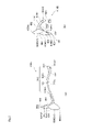
- FIG. 1(a) shows a plan view of the maxillary reference denture and corresponds to FIG. 12 of Patent Document 4
- FIG. 1(b) shows a plan view of the mandibular reference denture.
- FIG. 13 of Patent Document 4 shows a cross-sectional view of a complete denture type maxillary denture and a mandibular denture produced by the method described in Patent Document 4 using the maxillary reference denture and the mandibular reference denture shown in FIG. , corresponds to FIG. 1 of Patent Document 4.
- FIG. 1(a) shows a plan view of the maxillary reference denture and corresponds to FIG. 12 of Patent Document 4
- FIG. 1(b) shows a plan view of the mandibular reference denture.
- FIG. 2(a) shows a vertical sectional view at approximately the center of the canine teeth of the maxillary denture
- FIG. 2(b) shows a vertical sectional view at approximately the center of the canine teeth of the mandibular denture.
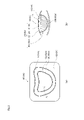
- This figure shows a package containing a loop-shaped string-shaped molded body corresponding to the planar shape of the base edge of the maxillary reference denture described in Patent Document 4, according to an embodiment of the package of the present invention. It is a figure shown typically.
- FIG. 3(a) is a perspective plan view of the package
- FIG. 3(b) is an end view showing the cross-sectional structure between the symbols Z A and Z A ' shown in FIG. 3( a). be.
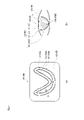
- FIG. 4(a) is a perspective plan view of the package
- FIG. 4(b) is an end view showing the cross-sectional structure between the reference numerals Z B -Z B ' shown in FIG. 4(a). be.
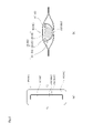
- FIG. 3 is a diagram schematically showing a wrapped package.
- FIG. 5(a) is a perspective plan view of the package
- FIG. 5(b) is an end view showing the cross-sectional structure between the symbols Z C -Z C ' shown in FIG. 5(a). be.
- the (uncured) curable denture base material is applied to the region (build-up/transfer region) where the base denture non-conforming space It is preferable to serve slightly more than the volume of .
- the curable denture base material a chemically polymerized block material prepared by mixing a powder material and a liquid agent at the time of use, or a prepackaged photopolymerized block material can be used.
- the curable denture base material piled up in the build-up/transfer area is scraped off little by little using a spatula or spatula, thereby removing the curable denture material. It is necessary to repeat the operation of shaping the flooring material. In this case, it is likely that the amount of food served partially becomes excessive or insufficient. In addition, if the amount to be applied at one time is too small, it is necessary to repeat the application many times to form a layer, which may cause gaps or partial peeling at the interface between the laminated layers. Become.
- the present inventors believe that it is effective to satisfy the following conditions (i) and (ii) in order to solve the above problems. found the body (i) A photocurable denture base material is used as the curable denture base material. (ii) Provide the operator with a string-shaped photocurable denture base material so that a certain amount of the photocurable denture base material can be easily applied to the build-up/transfer area.
- the package of the present embodiment is used in the method of manufacturing a denture using a reference denture exemplified in Patent Document 4, etc.
- the build-up/transfer process is preferably used to improve work efficiency while ensuring a certain level of quality regardless of the skill level of the operator.
- the form of use of the packaging body of the present embodiment is not limited to use in manufacturing dentures using the reference dentures exemplified in Patent Document 4, etc., and other than the reference dentures exemplified in Patent Document 4, Of course, it can also be suitably used in the case of performing the build-up/transfer step in the method of manufacturing a denture using the "other reference denture".
- the method of use is not particularly limited.
- the packaging body of the present embodiment is used when performing the build-up/transfer process in a method of manufacturing a denture using a reference denture. Remarkable effects are obtained when used in the build-up/transfer step (C2) and/or (C3) in the denture manufacturing method using the reference denture described in Patent Document 4. Therefore, prior to describing the details of the packaging body of the present embodiment, a brief description of the technical content described in Patent Document 4 regarding a reference denture and a method for producing a denture using the reference denture (particularly, the build-up/transfer step) will be given. to explain. Based on these explanations, the details of the package of the present embodiment will be explained. However, the description of the technical content described in Patent Document 4 is merely provided for the purpose of facilitating the understanding of the package of the present embodiment by the readers of the specification of the present application.
- the notation "x to y" using numerical values x and y means “x or more and y or less”. In such notation, when only the numerical value y is given a unit, the unit is also applied to the numerical value x.
- the term “(meth)acrylic” means both “acrylic” and “methacrylic”.
- the term “(meth)acrylate” means both “acrylate” and “methacrylate”
- the term “(meth)acryloyl” means both “acryloyl” and "methacryloyl”.
- the reference denture is composed of a reference denture base member and an artificial tooth fixed and held by the reference denture base member, and has a mucosal surface facing the alveolar ridge mucosa and at least one of the buccal mucosa and the tongue. It is a member having a polishing surface that is a contactable surface and a floor rim forming a boundary between the mucosal surface and the polishing surface.
- the string-like molded body which is the object to be packaged in the packaging body of the present embodiment, is used to improve the workability when building up the curable denture base material on the reference denture.
- the reference denture described in Patent Document 4 will be described below with reference to FIG. The disclosure of Patent Document 4 is incorporated herein by reference.
- FIG. 1(a) is a diagram showing a planar view of the maxillary reference denture described in Patent Document 4, and is a diagram for explaining the length of each part that defines a suitable planar shape.
- FIG. 1(b) is a plan view showing the shape of the lower jaw reference denture described in Patent Document 4, and is a diagram for explaining the length of each part that defines a suitable planar shape.
- left-right direction refers to the direction viewed from the patient side.
- right side refers to the left side in FIG. ” refers to the right side in FIG. 1(a) and the left side in FIG. 1(b).
- the maxillary reference denture 1A corresponds to the left pterygomaxillary notch on the trailing edge of the floor (the floor edge on the throat side).
- the point corresponding to the left postmolar prominence of the rear edge of the floor is defined as the first reference point for the maxilla (for the mandible): P(p). do.
- the point corresponding to the right postmolar prominence be the second reference point for the upper jaw (for the lower jaw): Q(q).
- the point corresponding to the upper (lower) labial frenulum corresponding to the median of the labial floor edges 3A1 and 3B1 is defined as a third reference point for the upper jaw (for the lower jaw): O(o).
- a line segment connecting P(p) and Q(q): PQ(pq) is defined as a reference length.
- a suitable planar shape is defined at predetermined positions on two reference line segments OP (op) and OQ (oq) connecting the third reference point, the first reference point and the second reference point, respectively. Lengths from points P1 (p1), P2 (p2), P3 (p3), Q1 (q1), Q2 (q2), Q3 (q3) to floor edges 3A and 3B (details will be described later), and It means a shape in which the ratio of the length of the line segment OM (om) when the midpoint of the line segment PQ (pq) is M (m) to the reference length is within a predetermined range.
- the reference point and the plurality of points (points) do not necessarily exist on the same plane. treated as
- the plurality of points P1 (p1), P2 (p2), P3 (p3), Q1 (q1), Q2 (q2), Q3 (q3) are divided into the maxillary reference denture 1A and the mandibular reference denture 1B.
- the relative length normalized in the case will be described.
- the points on the line segment OP are determined to intersect the left side of the floor edge 3A (right side in the figure), and the points on the line segment OQ are determined to intersect the right side of the floor edge 3A (left side in the figure).
- points D1, D2 and D3 are determined as points corresponding to points P1, P2 and P3, and points E1, E2 and E3 are determined as points corresponding to points Q1, Q2 and Q3.
- the length from each point P1, P2, P3, Q1, Q2, Q3 to the floor edge 3A is the line segment P1D1, the line segment P2D2, the line segment P3D3, the line segment Q1E1, the line segment Q2E2, and the line segment Q3E3. It means the relative length to the minute PQ.
- the preferred planar shape of the maxillary reference denture 1A is such that the relative length of the line segment OM is 0.76 to 0.98, and the relative lengths of P1D1 and Q1E1 are respectively 0.11 to 0.98. 0.36, the relative lengths of the line segment P2D2 and the line segment Q2E2 are respectively 0.19 to 0.45, and the relative lengths of the line segment P3D3 and the line segment Q3E3 are respectively 0.16 to 0.45.
- the maxillary reference denture 1A having such a shape is suitable for producing dentures using the package of the present embodiment.
- the Preferred Planar Shape of the Mandibular Reference Denture 1B As shown in FIG. are points corresponding to points P1, P2, P3, Q1, Q2, Q3, and M, which are points of .
- the length from each point p1, p2, p3, q1, q2, q3, m to the floor edge 3B includes the length between each point and the front floor edge 3B, The length between the front floor edge 3B and the rear floor edge 3B is included.
- the length between each point and the front floor edge 3B is the line segment P1D1, the line segment P2D2, and the line segment Line segment p1d1, line segment p2d2, line segment p3d3, line segment q1e1, line segment q2e2, line segment q3e3, and line segment corresponding to P3P3, line segment Q1E1, line segment Q2E2, line segment Q3E3, and line segment OM, respectively. om. Also, the length between the front floor edge 3B and the rear floor edge 3B with the points p1, p2, p3, q1, q2, and q3 as passing points is defined as follows.
- a perpendicular line to the line segment op or line segment oq on which the points p1, p2, p3, q1, q2, and q3 are present is determined to intersect with the rear floor edge 3B.
- b1, b2 and b3 are determined as points corresponding to p1, p2 and p3, and c1, c2 and c3 are determined as points corresponding to q1, q2 and q3.
- the length between the front floor edge 3B and the rear floor edge 3B is defined by connecting points p1, p2, p3, q1, q2, q3 and the intersections with the floor edges 3B on both sides thereof.
- a preferable planar shape of the reference denture 1B for the mandible is specifically that the relative length of the line segment om is 0.74 to 0.94, and the relative lengths of the line segment p1d1 and the line segment q1e1 are respectively 0.74 to 0.94. 11 to 0.32, the relative lengths of the line segment p2d2 and the line segment q2e2 are respectively 0.13 to 0.34, and the relative lengths of the line segment p3d3 and the line segment q3e3 are respectively 0.14 to 0.32.
- the relative lengths of the line segment d1b1 and the line segment e1c1 are respectively 0.14 to 0.40
- the relative lengths of the line segment d2b2 and the line segment e2c2 are respectively 0.19 to 0.41
- the lower jaw reference denture 1B having such a shape is suitable for producing dentures using the package of the present embodiment.
- the reference dentures 1A and 1B and the dentures 4A and 4B have reference denture base members 7A and 7B and artificial teeth 60A and 60B held and fixed to the gum-corresponding portions of the reference denture base members 7A and 7B. They have a common structure in terms of points.
- the adjustment member 9 is a hardened material obtained by curing the string-shaped molding (light-curing denture base material) built up and transferred to the reference dentures 1A and 1B in the (C) build-up/transfer step. .
- the tips of the floor edges 4A3 and 4B3 face the mucosal surfaces 4A1 and 4B1, and the tips of the floor rims 3A and 3B also face the mucosal surfaces.
- the reference denture base members 7A and 7B are used in the (C) build-up/transfer step. After building up the curable denture base material at a predetermined position on the mucosal surfaces 4A1 and 4B1, transferring the shape of the patient's oral cavity, and further forming the margin (D) in the curing step, the curable denture base material to cure. And thereby, a denture as shown in FIG. 2 is produced.
- the (C) step includes (C1) base central regions 5A1 and 5B1, (C2) base front regions (front base wing portions) 5A2 and 5B2, and (C3) base rear region 5A3 of the reference denture base members 7A and 7B. , 5B3, and the curable denture base material cured in each region is applied to each adjustment member 9 in the denture 4A, 4B, namely (C1) central adjustment members 9A1, 9B1, (C2) front adjustment members 9A2, 9B2. and (C3) the rear adjustment members 9A3 and 9B3, and the dentures 4A and 4B fitted to the oral cavity shape of each patient are manufactured.
- the amount of the curable denture base material applied is small, it is necessary to repeat the operation of applying additional material after the transfer and then performing the transfer again.
- the amount of partial filling may be excessive or insufficient, voids may occur at the interface between layers when laminating hardenable denture base materials, and partial peeling may occur during transfer. becomes.
- the amount of filling is too large, it is difficult to transfer, so it is necessary to repeat the operation of reducing the amount of filling and performing transfer again. Furthermore, even if the transfer can be performed, the overhanging portion is wasted, which is not economical, and furthermore, there are cases where a difference occurs in the state of transfer.
- the package of the present embodiment is a plastically deformable photocurable denture base material that is to be packaged and is molded into a string-like molded body to prepare a denture. It has a major feature in that it can be supplied at any time. By using the string-shaped molded body, anyone can easily grasp the exact amount of the photocurable denture base material used for build-up/transfer as the length of the string-shaped molded body. Therefore, it becomes very easy to build up and transfer an optimum amount of the photocurable denture base material to the building up/transferring surface regardless of the skill level of the operator.
- the reference dentures used for making dentures are often provided in several standard sizes such as S size, M size, and L size.
- S size the amount of photocurable denture base material required for the build-up/transfer process
- M size the amount of photocurable denture base material required for the build-up/transfer process
- L size the amount of photocurable denture base material required for the build-up/transfer process
- the string-shaped molded body should have a predetermined cross-sectional area so that it is easy to build up and transfer an appropriate amount of photocurable denture base material to each size of standard denture. is preferred.
- cross-sectional area means the cross-sectional area of the cross section orthogonal to the length direction of a string-shaped molded object.
- the present inventors further studied a particularly suitable range as a predetermined cross-sectional area in order to improve work efficiency while ensuring quality above a certain level without being affected by the skill level of workers. did. Therefore, when a denture is produced using a reference denture, the inventors of the present invention avoid excessive use of the photocurable denture base material (while eliminating waste), and make it easier to perform transfer and margin formation. From this point of view, the amount of the photocurable denture base material required in (C) the build-up/transfer process was examined.
- (C) the amount of the photocurable denture base material required in the build-up/transfer process is the maximum value of the cross-sectional area of each adjustment member 9 (filling the non-conforming space of the reference denture) in the denture to be manufactured. It was found that it is preferable to set it to about 1.1 to 1.5 times. Then, this knowledge was applied to (C2) and/or (C3) the build-up/transfer process and further studies were conducted.
- the present inventors found that if the cross-sectional area of the string-shaped molded body is 20 to 65 mm 2 , even if the amount of the photocurable denture base material used in these steps is somewhat excessive, , it has been confirmed that the need to replenish the photocurable denture base material (that is, the shortage of the amount used) is less likely to occur.
- the cross-sectional area of the string-like molded body is preferably 20 to 65 mm 2 , more preferably 22 to 60 mm 2 , even more preferably 24 to 55 mm 2 .
- the entire range from the lower limit value to the upper limit value of the cross-sectional area can be divided into a plurality of narrower ranges, and each division can be assigned to correspond to a reference denture of each size.
- a string-shaped molded body having a lower limit or a cross-sectional area slightly larger than the lower limit is used as an S-size reference denture
- a string-shaped molded body having a cross-sectional area between the lower limit and the median is used as an S size and a slightly larger cross-sectional area. It can be used as a reference denture for M size.
- the string-like forming body is a linear member
- the front build-up/transfer step and/or (C3) the rear build-up/transfer step if the length of the linear string-like formed body is long, it is appropriately cut, and if the length is insufficient. The operation is simplified by using it by adding it appropriately.
- the cross-sectional area of the string-shaped molded body is set to 20 to 65 mm 2 , even if it is used for any of several standard sizes of reference dentures such as S size, M size, and L size, light It becomes easier to perform the building-up/transferring steps (C2) and/or (C3) without replenishing the curable denture base material. For this reason, variations among workers in the quality of the build-up/transferred portion are further suppressed.
- planar shape of the string-like molded body defined by the grooves of the tray which will be described later, can be selected from any shape such as a linear shape or a loop shape.
- the planar shape of the string-shaped body is the shape shown in (1) or (2) above, for example, the reference dentures 1A and 1B are placed on the tray while the string-shaped body is accommodated in the tray.
- the string-like molded body is arranged and brought into close contact with the lines along the tops of the floor edges 3A and 3B by placing them.
- the string-shaped molded article (photocurable denture base material) can be uniformly arranged without being deviated from the line. Therefore, the build-up/transfer step (C2) and/or (C3) can be performed more easily.
- the cross-sectional area of the string-shaped molded body does not necessarily have to be constant in the length direction of the string-shaped molded body, but from the viewpoint of manufacturing efficiency of the package, it is constant in the length direction. is preferred.
- “constant” means (1) completely constant (variation in cross-sectional area in the longitudinal direction is 0%), or (2) substantially constant (variation in cross-sectional area in the longitudinal direction is within ⁇ 10%, preferably means within ⁇ 5% (excluding exactly 0%).
- the length (L) of the string-like molded body is not particularly limited, but it is usually preferably 50 to 400 mm, more preferably 50 to 400 mm.
- the string-like forming body is a loop-shaped member that is assumed to be used up after one use
- its length (L) corresponds to the total length of the base rims 3A and 3B of the reference dentures 1A and 1B. length is preferred.
- the ratio (L/D) of the length (L) of the string-like molded body to the maximum width (D) of the cross section perpendicular to the longitudinal direction of the string-shaped molded body (L/D) is usually preferably 4 or more, and 4 to 48. is preferred, and 5 to 36 are more preferred.
- the cross-sectional shape of the cross section perpendicular to the longitudinal direction of the string-shaped molded body is not particularly limited, and may be, for example, circular. It is preferable that the shape approximates the cross-sectional shape of the cured product (adjusting member 9 referred to in FIG. 2).
- Such cross-sectional shapes include a semicircular shape or a crescent shape.
- semiconductor shape means not only (i) a semicircular shape with a central angle of 180 degrees, but also Preferably, a substantially semicircular shape with a center angle of about 170 to 190 degrees (excluding exactly 180 degrees at each center), (iii) a center angle of about 160 to 200 degrees (excluding exactly 180 degrees at each center), preferably It also means a substantially semi-elliptical shape of about 170 to 190° (except that each center is exactly 180°), and (iv) a shape similar to any of (i) to (iii).
- “crescent shape” means that when two circles, which may have different diameters, are arranged so that the centers of the circles are shifted so that they partially overlap, the shape of the non-overlapping portion or an approximation thereof shape. If the cross-sectional shape is semi-circular or crescent-shaped, transfer and edging can be made easier.
- the semi-circular or crescent-shaped cross-sectional shape is particularly useful when building up and transferring the string-shaped molded body along the floor edges 3A and 3B of the reference dentures 1A and 1B in comparison with the circular cross-sectional shape.
- the contour line of the semicircular cross-sectional shape is composed of an arc portion such as a circular arc or an elliptical arc, which is a curved line projecting in one direction, and a straight line, V-shaped or V-shaped connecting both ends of the arc portion.
- the outline of the crescent-shaped cross-section is composed of an arc portion composed of a curved line protruding in one direction, such as a circular arc or an elliptical arc. , and a chord portion formed by a curved line connecting both ends of the arc.
- the base edge of the reference denture has a convex cross-sectional shape that protrudes toward the mucous membrane surface. Therefore, a string-shaped molded body having a circular cross-sectional shape is arranged at the top of the floor edges 3A and 3B, and the edge is formed by deforming the string-shaped molded body so as to cover the vicinity of the top of the floor edges 3A and 3B. When doing so, a large deformation operation is required.
- a string-like molded body having a semicircular or crescent-shaped cross section is placed on the floor edges 3A, 3B so that the central part of the chord part of the cross-sectional outline faces the top part of the floor edges 3A, 3B.
- the edge by deforming the string-like molded body so as to cover the vicinity of the top of the floor edges 3A and 3B, the deformation operation can be further reduced. Therefore, the semicircular or crescent shape of the cross section can improve the workability in forming the margin more than the circular shape of the cross section.
- a plastically deformable photocurable material is used as the curable denture base material. Since the material is usually in the form of a paste containing a liquid component, the string-like molded body is accommodated in the inner space of the light-shielding member having an airtight inner space. If the member that accommodates the string-like molded body does not have a light-shielding property, the photocurable denture base material will inevitably be cured by ambient light. In addition, if the member for housing the string-like molded body is not airtight, there is a possibility that volatile components will decrease and liquid leakage will occur.
- airtightness means that solid or liquid foreign matter cannot enter from the outside and loss or evaporation of the contents stored in the internal space is prevented during normal handling, transportation, or storage conditions. It means to make it possible. However, it is permissible for a very small amount of gas (oxygen in the air, etc.) to permeate through members such as films and partitions constituting the light-shielding member, which do not adversely affect the storage of the contents.
- gas oxygen in the air, etc.
- the light-shielding member used in the packaging body of the present embodiment includes (i) a tray having a groove for accommodating the string-shaped molded body, (ii) a bag body for accommodating the tray inside, and the opening of the groove. and at least one member selected from the group consisting of a lid material that seals the part.
- This tray is characterized in that it has grooves for accommodating the string-like molded body, defining the planar shape of the string-like molded body, and preventing deformation of the cross-sectional shape of the string-shaped molded body. By using such a tray, it is possible to prevent deformation of the cross-sectional shape of the string-like formed body during manufacturing and distribution of the package of the present embodiment.
- the package of this embodiment it is necessary to accommodate the string-shaped molded body in a space in which light blocking and airtightness are ensured. Therefore, (a) when the light-shielding member is composed of a tray and a bag, a light-shielding and airtight bag is used. Incidentally, the tray may or may not have a light shielding property. (b) When the light-shielding member is composed of a tray and a lid member, a light-shielding tray and a light-shielding lid member are used. Airtightness is ensured by sealing the opening of the groove of the tray with a cover member.
- the light-shielding member is composed of a bag body, a tray, and a lid material
- the light-shielding property and airtightness can be obtained according to any of the first to fourth aspects described below.
- a first mode there is a mode using a light-shielding and airtight bag (for example, a black vinyl bag having a sealing mechanism such as a chuck).
- the tray and lid may or may not have a light blocking effect.
- the airtightness of the internal space formed by the tray and the lid member may be ensured, or may not be ensured.
- a second mode there is a mode using an airtight bag body (for example, a transparent vinyl bag having a sealing mechanism such as a chuck) which does not have a light shielding property.
- an airtight bag body for example, a transparent vinyl bag having a sealing mechanism such as a chuck
- a light-shielding tray and a light-shielding lid are used.
- the opening of the groove of the tray is sealed with a lid member, if the inner space formed by the tray and the lid member can be sealed so as not to enter the external light, the inner space can be sealed. Airtightness may or may not be ensured.
- a third mode there is a mode that uses a bag that has a light-shielding property but is not airtight (for example, a black plastic bag that does not have a sealing mechanism such as a zipper). In this case, airtightness is ensured by sealing the opening of the groove of the tray with a cover member. In addition, the tray and lid material may or may not have a light shielding property.
- a fourth mode there is a mode using a bag body that does not have light-shielding properties and airtightness (for example, a transparent plastic bag that does not have a sealing mechanism such as a chuck). In this case, a light-shielding tray and a light-shielding lid are used. Airtightness is ensured by sealing the opening of the groove of the tray with a cover member.
- a light-shielding tray and a lid material are arranged in a light-shielding and airtight bag body, and the opening of the groove of the tray is sealed by the lid material.
- the lid material is particularly preferred.
- both the light-shielding property and the airtightness can be ensured in each of the bag body and the member in which the tray and the lid member are combined. Therefore, even if the bag is damaged during storage or transportation of the package, the tray and the lid member can still ensure light blocking and airtightness.
- FIG. 3A and 3B are diagrams schematically showing a package in which a loop-shaped string-shaped molded body corresponding to the planar shape of the floor edge 3A of the maxillary reference denture 1A is accommodated, and FIG. 3A is a plan view thereof.
- 3B is a perspective view
- FIG. 3B is a cross-sectional view of a portion indicated by reference numeral Z A -Z A ' in FIG. 3A.
- 4A and 4B are diagrams schematically showing a package in which a loop-shaped string-shaped molded body corresponding to the planar shape of the floor edge 3B of the lower jaw reference denture 1B is accommodated
- FIG. 4A is a plan view thereof.
- FIG. 4B is a perspective view
- FIG. 4B is a cross-sectional view of a portion indicated by reference numeral Z B -Z B ′ in FIG. 4A.
- FIG. 5 schematically shows a package containing a linear (that is, bar-shaped) cord-shaped formed body that can be used for making a denture 4 using either the maxillary reference denture 1A or the mandibular reference denture 1B.
- 5(a) is a perspective plan view thereof
- FIG. 5(b) is a cross-sectional view of a portion indicated by reference numeral Z C -Z C ' in FIG. 5(a).
- the dimensional ratio of each component in these drawings does not necessarily match the dimensional ratio of the actual package.
- the thickness of the bag body 12 is drawn thicker than the actual one.
- the packaging body 10 of the present embodiment has a string-shaped molded body 11 and an airtight internal space, and a light shielding device that accommodates the string-shaped molded body 11 in this internal space. and an elastic member 15 .
- the string-like molded body 11 is a member obtained by molding a paste-like photocurable denture base material having plastic deformation property into a string-like shape having a predetermined cross-sectional area, cross-sectional shape and length.
- the light-shielding member 15 has a bag body 12 , a tray 151 and a lid member 14 .
- a tray 151 and a lid member 14 for sealing the opening of the groove 150 of the tray 151 are arranged inside the bag body 12 .
- the tray 151 has a groove 150 for accommodating the string-like molded body 11, defining the planar shape of the string-shaped molded body 11, and preventing deformation of the cross-sectional shape of the string-shaped molded body 11.
- the photocurable denture base material constituting the string-shaped molded body 11 is not particularly limited as long as it is a photocurable denture base material.
- the material disclosed in Patent Document 4 is particularly limited. can be used without Such photocurable denture base materials are usually ⁇ 1>, for example, methyl (meth) acrylate, ethyl (meth) acrylate, 2-(meth) acryloxyethyl propionate, ethylene glycol di(meth)
- a polymerizable monomer (monomer component) composed of a (meth)acrylate monomer such as acrylate, nonaethylene glycol di(meth)acrylate, trimethylolpropane tri(meth)acrylate, ⁇ 2> such as camphorquinone, benzyl, At least a photopolymerization initiator such as diacetyl or cyclobutenedione, ⁇ 3> for example, an organic filler such as polymethyl (meth)acrylate or polyethyl (me
- such a plastically deformable property is, for example, that a part of the organic filler such as polymethyl (meth) acrylate (i) dissolves in the polymerizable monomer, or (ii) dissolves due to the polymerizable monomer. It is expressed by swelling and softening, or (iii) an interaction similar to (ii) above occurs.
- the photocurable denture base material is preferably a material whose cured body has an elastic modulus of 0.50 to 3.0 GPa. This allows the denture to follow the deflection of the jawbone when the patient opens and closes the mouth while minimizing the deformation of the denture due to the stress generated when the patient masticates, making it extremely easy to obtain a comfortable fit. becomes.
- the photocurable denture base material contains 20 to 80 parts by mass of an organic filler having a molecular weight of 50,000 to 1,000,000 per 100 parts by mass of the polymerizable monomer. is preferred. In this case, it is preferable to use a polymerizable monomer having a molecular weight of 500 or less, from the viewpoint of facilitating the production of a plastically deformable photocurable denture base material. .
- the tray 151 is covered with the lid member 14 in the state where the string-shaped molded body 11 is housed in the groove 150 .
- the lid member 14 may cover the opening of the tray 151, that is, the entire groove 150 in plan view.
- Materials for the tray 151, the lid member 14, and the bag body 12 are appropriately selected from resin materials and metal materials according to the form of light shielding and sealing. Resin is used. When imparting a light-shielding property to these, a vapor-deposited film or sheet obtained by vapor-depositing aluminum or a laminated film or sheet obtained by laminating an aluminum film is preferably used. Such a laminate film or sheet preferably has a sealant layer because it can be sealed or hermetically sealed by heat sealing. It is further preferred to have a layer of material that is impermeable to the body.
- the oxygen existing in the space S in the bag 12 has the function of inhibiting the polymerization of the string-like molded body 11 (photocurable denture base material) during storage.
- general-purpose thermoplastic resins such as polyethylene, polypropylene, and polyethylene terephthalate, which have a certain degree of oxygen permeability, as materials for the tray 151 and the lid member 14 .
- the tray 151 and the lid member 14 are made of, for example, polyethylene terephthalate. It is preferably composed of a material having a low permeability to volatile polymerizable monomers and a certain degree of oxygen permeability. This makes it easy to suppress deterioration in the plastic deformability of the string-like formed body 11 due to permeation of the volatile polymerizable monomer through the tray 151 and the lid member 14 .
- the thickness of the bag 12, the tray 151, and the lid member 14 may be appropriately determined within a range that does not easily break and does not hinder the operation of taking out the string-like molded body 11.
- the tray 151 preferably has appropriate flexibility or elasticity so that it can be easily pushed out (pressed) with a finger and deformed to push out and take out the cord-like molded body 11 inside. From this point of view, the thickness of tray 151 is preferably in the range of 100 to 2000 ⁇ m.
- the thickness of the lid member 14 is preferably 5 to 250 ⁇ m from the viewpoint of ease of operation for removing the lid member 14 from the tray 151 .
- the thickness of the bag 12 is preferably 5 to 250 ⁇ m from the viewpoint that the bag 12 can be easily opened.
- cross-sectional shape is (i) semicircular, (ii) approximately semicircular, (iii) semielliptical, and (iv) A substantially semielliptical shape or a shape approximating any of (v) (i) to (iv) is preferred.
- 3(a), 4(a) and 5(a) which are cross-sectional views represented by Z A -Z A ' cross-section, Z B -Z B ' cross-section and Z C -Z C 'cross-section; 3(b), FIG. 4(b), and FIG.
- the groove 150 has a substantially semicircular cross-sectional shape.
- the cross-sectional width (chord length) of the groove 150A is preferably 8 to 12 mm, and the height is 5. ⁇ 7 mm is preferred.
- the cross-sectional shape of the groove 150B preferably has a width of 5 to 8 mm and a height of 5 to 8 mm. preferable.
- the string-shaped molded body 11 can be easily obtained by, for example, extruding or press-molding a photocurable denture base material.
- the cross-sectional area and cross-sectional shape of the string-like molded body 11 perpendicular to the longitudinal direction, and the length of the string-shaped molded body 11 can be adjusted by appropriately selecting molding conditions. For example, if a die is used in extrusion molding, a string-like molded body 11 having a desired cross-sectional area and cross-sectional shape and an arbitrary length can be obtained. do it.
- the string-shaped molded body 11 is appropriately bent so as to have a loop shape consisting of a desired planar shape, and then both ends of the string-shaped molded body 11 are connected.
- the groove 150 of the tray 151 defines the planar shape of the string-shaped molded body 11 housed in the light-shielding member 15 and prevents deformation of the cross-sectional shape. Therefore, the cross-sectional shape of the string-like formed body 11 (however, the shape of the arc portion of the cross-sectional outline of the cross-sectional shape) has a shape that “matches” the cross-sectional shape of the groove 150 .
- the cross-sectional shape of the string-like formed body 11 has a semicircular shape with a central angle of 180 degrees in the examples shown in FIGS. 3(b), 4(b) and 5(b).
- the cross-sectional shape of the string-shaped molded body 11 (however, the shape of the chord part of the cross-sectional contour line of the cross-sectional shape) It is more preferred to have a shape that "matches" the cross-sectional shape of the inner wall surface of the .
- “match” means perfect match or approximate match.
- the cross-sectional shape of the string-like molded body 11 completely matches the cross-sectional shape of the groove 150 and the inner wall surface of the lid member 14, and the entire surface of the arc of the cross-sectional outline of the string-shaped molded body 11 is A mode is shown in which the cord portion of the cross-sectional outline of the string-like molded body 11 is in close contact with the inner wall surface of the lid member 14 as well as in close contact with the inner wall surface of the groove 150 .
- the outer peripheral surface of the string-shaped molded body 11, the lid member 14, and the inner wall surface of the groove 150 are partially A mode of contact (in other words, a mode in which a gap is partially generated) may be used.
- the planar shape of the string-shaped molded body 11 is preferably linear or loop-shaped.
- the loop-shaped string-shaped molded bodies 11A and 11B have a length suitable for building up on the peripheral edge of the mucosal surface of the reference dentures 1A and 1B (that is, the floor edges 3A and 3B) used to fabricate the dentures 4A and 4B.
- the circumferential length X of the loop-shaped string-shaped formed bodies 11A and 11B is the same as the circumferential length Y of the floor rims 3A and 3B, or slightly longer than the circumferential length of the floor rims 3A and 3B (peripheral length Y It is preferable to set the length to exceed 100% and 130% or less).
- circumferential lengths Y that is, circumferential lengths Y1, Y2, Y3, . . .
- a looped string is attached to each of the perimeter lengths Y1, Y2, ... Yn.
- the peripheral lengths X1, X2, . . . Xn of the shaped bodies 11A, 11B can be set.
- n is an integer of 1 or more.
- the length of the linear string-shaped molded body 11C is not particularly limited.
- the linear string-shaped molded body 11C has the following drawbacks: (1) By using one string-shaped molded body 11C, the rims of the mucosa surfaces of the reference dentures 1A and 1B (that is, the floor edges 3A and 3B) are built up. or (2) by combining two string-shaped molded bodies 11C, the peripheral edges of the mucosa surfaces of the reference dentures 1A and 1B (that is, the floor edges 3A and 3B) It preferably has a length suitable for building up.
- the length X of the string-shaped molded body 11C is the same as the peripheral length Y of the base rims 3A and 3B of the reference dentures 1A and 1B used for making the denture, or It is preferable to set the circumference slightly longer than the circumferences of 3A and 3B (more than 100% and 130% or less of the circumference Y).
- planar shape of the string-like molded body 11C is linear or rod-shaped as shown in FIG. It can also be filled without gaps.
- planar shape, cross-sectional shape and length of the groove 150C match the planar shape, cross-sectional shape and length of the string-like formed body 11C, respectively.
- Method of using the packaging body of the present embodiment In the case of producing a denture using the packaging body of the present embodiment, the following procedure can be carried out. That is, (A) build up a plastically deformable photocurable denture base material on at least one build-up target region selected from at least a portion of the base rim and at least a portion of the mucosal surface of the reference denture, and then ( B1) After placing the reference denture on which the photocurable denture base material is built up at an appropriate position in the patient's oral cavity, the shape of the mucous membrane in the patient's oral cavity is transferred to the photocurable denture base material and margin formation is performed.
- (B2) The reference denture on which the photocurable denture base material is built up is placed in a virtual articulator to which the patient's intraoral model is attached. After placing in an appropriate position on the occlusal plane, the shape of the patient's intraoral model is transferred to the photocurable denture base material and margin formation is performed to remove excess photocurable denture base material. - After passing through the transfer step; and the build-up/transfer step, a hardening step for hardening the curable denture base material is carried out.
- the photocurable denture base material is applied to the area to be built up, the string-like molded body taken out from the package of the present embodiment is used as the photocurable denture base material.
- the planar shape of the string-like formed body defined by the groove corresponds to the planar shape of at least a portion of the base edge.
- a shape is preferred.
- the bags 12A and 12B shown in FIGS. 3 and 4 are taken out.
- the string-like formed bodies 11A and 11B having loop-shaped planar shapes accommodated in the grooves 150A and 150B are taken out.
- the (C) build-up/transfer step is performed on the reference dentures 1A and 1B using the string-shaped formed bodies 11A and 11B that have been taken out.
- the packaging body 10C shown in FIG. 5 the same procedure as when using the packaging bodies 10A and 10B shown in FIGS. ) is taken out.
- the length and planar shape of the string-shaped molded body 11C are adjusted so that the string-shaped molded body 11C taken out has a shape suitable for building up the standard dentures 1A and 1B.
- the length is adjusted by appropriately cutting or connecting the string-shaped body 11C
- the planar shape is adjusted by appropriately curving the string-shaped body 11C.
- (C) build-up/transfer step is carried out in the same manner as in the case of using the packages 10A and 10B shown in FIGS.
- the linear (that is, bar-shaped) cord-shaped body 11C shown in FIG. 5 can be preferably used.
- the linear (that is, bar-shaped) cord-shaped formed body 11C (or part thereof) is placed in the base central region 5A1 (or the base central region 5B1) shown in FIG. 2(a) (or FIG. 2(b)).
- the chord part of the cross-sectional outline of the linear string-shaped molded body 11 faces the lower side in FIG. 2(a) (or the upper side in FIG. 2(b)).
- the reference denture 1A (or the reference denture 1B) on which the string-shaped formed body 11C is built up is arranged at an appropriate position on the virtual occlusal plane in the patient's oral cavity or in the articulator, and the shape of the mucosa in the patient's oral cavity or The shape of the patient's intraoral model is transferred to the photocurable denture base material (the build-up string-like molding 11C).
- the loop-shaped string-like formed bodies 11A and 11B shown in FIGS. 3 and 4 can be particularly preferably used.
- the reference dentures 1A and 1B are placed on the upper surfaces of the string-like molded bodies 11A and 11B accommodated in the grooves 150A and 150B so that the mucous membrane surface faces downward, and the reference is made to the string-shaped molded bodies 11A and 11B.
- the base edges 3A and 3B of the dentures 1A and 1B are brought into close contact.
- (2) the procedure shown in (1) above is performed with the positional relationship between the trays 151A and 151B and the reference dentures 1A and 1B reversed in the vertical direction.
- a linear (that is, rod-like) string-like molded body 11C shown in FIG. 5 can be used for building up the string-shaped molded body 11 on the floor edges 3A and 3B of the reference dentures 1A and 1B.
- the string-shaped molded body 11C can be cut (or two or more string-shaped molded bodies 11C can be connected) so as to have a shape suitable for building up on the reference dentures 1A and 1B, and used in a curved state. can.
- the planar shape and length of the string-shaped formed body 11C are curved so as to correspond to the planar shape and length of the peripheral portions (floor margins 3A and 3B) of the mucosa surfaces of the reference dentures 1A and 1B, and the length to adjust.
- the reference dentures 1A and 1B on which the string-shaped molded body 11 is built up by any of the building procedures shown in (1) to (3) above, are placed on an appropriate virtual occlusal plane in the patient's oral cavity or in the articulator. Then, the shape of the mucosa in the patient's oral cavity or the shape of the model in the patient's oral cavity is transferred to the photocurable denture base material (the built-up string-like molded body 11). Then, margin formation is performed substantially at the same time as the transfer, and excess hardening denture base material is removed.
- Reference denture of Patent Document 4 1A Reference denture for upper jaw of Patent Document 4 1B
- Reference denture for lower jaw of Patent Document 4 2A Reference denture base for upper jaw (corresponding to reference denture member for upper jaw) 2B
- Standard denture base for mandible corresponding to standard denture component for mandible
- 3A, 3B Floor edge 3A1, 3B1... Labial edge 3A2, 3B2... Buccal edge 4
- Denture 4A... Maxillary denture 4B Mandibular denture 4A1, 4B1... Mucous membrane surface 4A2, 4B2... Polished surface 4A3, 4B3 ... base edge 4A4, 4B4 ... neck 4A5, 4B5 ... base wing 5 ...
- denture base 5A maxillary denture base 5B ... maxillary denture base 5A1, 5B1 ... base central region 5A2, 5B2 ... base front region (front base wing part) 5A3 ... Base posterior region (palatal floor) 5B3 ... Base posterior region (lingual floor wing) 7 Reference denture base member 7A Reference denture base member for upper jaw 7B Reference denture base member for lower jaw 8 Reference denture member 8A Reference denture member for upper jaw 8B Reference denture member for lower jaw 9 Adjustment member 9A1, 9B1 Center Adjustment members 9A2, 9B2... Front adjustment member 9A3... Back adjustment member (palatal floor adjustment part) 9B3... Rear adjustment member (lingual floor wing adjustment part) 60, 60A, 60B...
- Light shielding member 15A An Light shielding member (maxillary loop shape) 15B...Light shielding member (lower jaw loop shape) 15C...Light shielding member (linear shape for upper and lower jaws) 150... Groove 150A... Groove (loop shape for upper jaw) 150B... Groove (loop shape for lower jaw) 150C... Groove (linear shape for upper and lower jaw) 151... Tray 151A... Tray (loop shape for upper jaw) 151B... Tray (loop shape for lower jaw) 151C... Tray (linear shape for upper and lower jaw) S... Gap
Landscapes
- Health & Medical Sciences (AREA)
- Oral & Maxillofacial Surgery (AREA)
- Dentistry (AREA)
- Epidemiology (AREA)
- Life Sciences & Earth Sciences (AREA)
- Animal Behavior & Ethology (AREA)
- General Health & Medical Sciences (AREA)
- Public Health (AREA)
- Veterinary Medicine (AREA)
- Dental Prosthetics (AREA)
- Dental Tools And Instruments Or Auxiliary Dental Instruments (AREA)
- Dental Preparations (AREA)
Priority Applications (6)
| Application Number | Priority Date | Filing Date | Title |
|---|---|---|---|
| EP22804605.8A EP4342419B1 (en) | 2021-05-18 | 2022-05-13 | Denture base material package and method for creating denture |
| CN202280027951.0A CN117119996B (zh) | 2021-05-18 | 2022-05-13 | 义齿基托用材料包装体及义齿的制造方法 |
| JP2023522632A JPWO2022244693A1 (cg-RX-API-DMAC7.html) | 2021-05-18 | 2022-05-13 | |
| BR112023021569A BR112023021569A2 (pt) | 2021-05-18 | 2022-05-13 | Embalagem de material de base de prótese dentária e método de produção para prótese dentária |
| US18/285,805 US20240366348A1 (en) | 2021-05-18 | 2022-05-13 | Denture base material package and method for creating denture |
| KR1020237034697A KR20240008829A (ko) | 2021-05-18 | 2022-05-13 | 의치상용 재료 포장체 및 의치의 제작 방법 |
Applications Claiming Priority (2)
| Application Number | Priority Date | Filing Date | Title |
|---|---|---|---|
| JP2021-083894 | 2021-05-18 | ||
| JP2021083894 | 2021-05-18 |
Publications (1)
| Publication Number | Publication Date |
|---|---|
| WO2022244693A1 true WO2022244693A1 (ja) | 2022-11-24 |
Family
ID=84140440
Family Applications (1)
| Application Number | Title | Priority Date | Filing Date |
|---|---|---|---|
| PCT/JP2022/020191 Ceased WO2022244693A1 (ja) | 2021-05-18 | 2022-05-13 | 義歯床用材料包装体および義歯の作製方法 |
Country Status (7)
| Country | Link |
|---|---|
| US (1) | US20240366348A1 (cg-RX-API-DMAC7.html) |
| EP (1) | EP4342419B1 (cg-RX-API-DMAC7.html) |
| JP (1) | JPWO2022244693A1 (cg-RX-API-DMAC7.html) |
| KR (1) | KR20240008829A (cg-RX-API-DMAC7.html) |
| CN (1) | CN117119996B (cg-RX-API-DMAC7.html) |
| BR (1) | BR112023021569A2 (cg-RX-API-DMAC7.html) |
| WO (1) | WO2022244693A1 (cg-RX-API-DMAC7.html) |
Cited By (1)
| Publication number | Priority date | Publication date | Assignee | Title |
|---|---|---|---|---|
| US20250134633A1 (en) * | 2023-10-27 | 2025-05-01 | Ivoclar Vivadent Ag | Method For Determining An Internal Structure Of A Dental Prosthesis Base, Method For The Production Of A Dental Prosthesis Base, Dental Prosthesis Base, Data-Processing Device, Computer Program And Computer-Readable Medium |
Citations (3)
| Publication number | Priority date | Publication date | Assignee | Title |
|---|---|---|---|---|
| JPH01120819U (cg-RX-API-DMAC7.html) * | 1988-02-05 | 1989-08-16 | ||
| JPH05192353A (ja) * | 1991-10-01 | 1993-08-03 | Ube Ind Ltd | 補綴義歯前駆体及び補綴義歯作成方法 |
| JP2017512613A (ja) * | 2014-03-20 | 2017-05-25 | ウルトラデント プロダクツ インコーポレイテッド | 犠牲組成物を含む包装システム |
Family Cites Families (13)
| Publication number | Priority date | Publication date | Assignee | Title |
|---|---|---|---|---|
| JPH0446491Y2 (cg-RX-API-DMAC7.html) | 1985-12-06 | 1992-11-02 | ||
| JPH0714401B2 (ja) * | 1986-08-13 | 1995-02-22 | 而至歯科工業株式会社 | 歯科用トレ− |
| JPH0650715B2 (ja) * | 1987-11-04 | 1994-06-29 | キヤノン株式会社 | 露光方法及びそれを用いた素子製造方法 |
| WO2002089696A2 (en) * | 2001-05-03 | 2002-11-14 | D-Tec-Dent Corporation | Duplication of lost dentures |
| US6730246B2 (en) * | 2001-05-03 | 2004-05-04 | William Raymond Price | Duplication of lost dentures |
| JP2004285023A (ja) * | 2003-03-25 | 2004-10-14 | Takahito Kanie | 義歯床用レジン補強材、それを用いた義歯床の製作方法 |
| US20090130624A1 (en) * | 2007-11-20 | 2009-05-21 | Benjamin Jiemin Sun | Methods and kits for making flexible dental guards |
| JP2017506528A (ja) * | 2014-01-09 | 2017-03-09 | ロンジウム アイピー リミテッド | 歯修復装置及び歯修復装置の使用方法 |
| JP2017064012A (ja) * | 2015-09-30 | 2017-04-06 | 株式会社DentalBank | 義歯床、人工歯、義歯および義歯の製造方法 |
| JP7036810B2 (ja) * | 2016-06-20 | 2022-03-15 | デンツプライ シロナ インコーポレイテッド | 層状歯科用製品を製造するための3次元造形材料系および方法 |
| RU2771108C2 (ru) | 2017-05-10 | 2022-04-26 | Токуяма Дентал Корпорейшн | Выравнивающее устройство для стандартных зубных протезов, набор для изготовления зубного протеза и способ изготовления зубного протеза с использованием такого выравнивающего устройства и такого набора |
| US12232913B2 (en) | 2019-03-28 | 2025-02-25 | Tokuyama Dental Corporation | Denture, reference denture, and denture manufacturing method |
| KR102950368B1 (ko) * | 2019-09-20 | 2026-04-09 | 소후 인코포레이티드 | 3d 프린터의 광조형 후의 포스트 큐어 방법 |
-
2022
- 2022-05-13 WO PCT/JP2022/020191 patent/WO2022244693A1/ja not_active Ceased
- 2022-05-13 BR BR112023021569A patent/BR112023021569A2/pt unknown
- 2022-05-13 KR KR1020237034697A patent/KR20240008829A/ko active Pending
- 2022-05-13 CN CN202280027951.0A patent/CN117119996B/zh active Active
- 2022-05-13 JP JP2023522632A patent/JPWO2022244693A1/ja active Pending
- 2022-05-13 US US18/285,805 patent/US20240366348A1/en active Pending
- 2022-05-13 EP EP22804605.8A patent/EP4342419B1/en active Active
Patent Citations (3)
| Publication number | Priority date | Publication date | Assignee | Title |
|---|---|---|---|---|
| JPH01120819U (cg-RX-API-DMAC7.html) * | 1988-02-05 | 1989-08-16 | ||
| JPH05192353A (ja) * | 1991-10-01 | 1993-08-03 | Ube Ind Ltd | 補綴義歯前駆体及び補綴義歯作成方法 |
| JP2017512613A (ja) * | 2014-03-20 | 2017-05-25 | ウルトラデント プロダクツ インコーポレイテッド | 犠牲組成物を含む包装システム |
Non-Patent Citations (1)
| Title |
|---|
| See also references of EP4342419A4 * |
Cited By (1)
| Publication number | Priority date | Publication date | Assignee | Title |
|---|---|---|---|---|
| US20250134633A1 (en) * | 2023-10-27 | 2025-05-01 | Ivoclar Vivadent Ag | Method For Determining An Internal Structure Of A Dental Prosthesis Base, Method For The Production Of A Dental Prosthesis Base, Dental Prosthesis Base, Data-Processing Device, Computer Program And Computer-Readable Medium |
Also Published As
| Publication number | Publication date |
|---|---|
| US20240366348A1 (en) | 2024-11-07 |
| CN117119996B (zh) | 2026-06-09 |
| EP4342419C0 (en) | 2025-12-17 |
| BR112023021569A2 (pt) | 2023-12-19 |
| JPWO2022244693A1 (cg-RX-API-DMAC7.html) | 2022-11-24 |
| EP4342419A4 (en) | 2024-10-23 |
| KR20240008829A (ko) | 2024-01-19 |
| CN117119996A (zh) | 2023-11-24 |
| EP4342419A1 (en) | 2024-03-27 |
| EP4342419B1 (en) | 2025-12-17 |
Similar Documents
| Publication | Publication Date | Title |
|---|---|---|
| US11382717B2 (en) | Devices and a seamless, single load cavity preparation and filing technique | |
| US7217131B2 (en) | Method for dental restoration and kit | |
| US8753114B2 (en) | Method for dental restoration and related kit | |
| US8366445B2 (en) | Method for dental restoration and related kit | |
| US8393897B2 (en) | Methods and devices for diastema closure | |
| US6386865B1 (en) | System for fabrication of indirect dental restoratives | |
| US20100062394A1 (en) | Preformed malleable multilayer dental articles | |
| US20100021868A1 (en) | Dental crown forms and methods | |
| CN101516288A (zh) | 预成形延展性实心牙冠 | |
| US20050042576A1 (en) | Dental article forms and methods | |
| US20040053189A1 (en) | Dental light curing member and method | |
| JP7531529B2 (ja) | ブレーシングボディ(bracing body)を有する付加製造義歯床 | |
| JP2020534096A (ja) | 歯間隙間を閉鎖するための方法と装置 | |
| US5695340A (en) | Dental restoration system and method | |
| KR20240008829A (ko) | 의치상용 재료 포장체 및 의치의 제작 방법 | |
| JPH0254741B2 (cg-RX-API-DMAC7.html) | ||
| EP3206624B1 (en) | Method of curing a dental article | |
| RU2851718C2 (ru) | Комплект материалов для базиса зубного протеза и способ изготовления зубного протеза | |
| KR20220072370A (ko) | 미리 성형되어 제공되는 변형 가능한 치아 모양의 보철물 및 그 제조방법 | |
| JPWO2022244693A5 (cg-RX-API-DMAC7.html) | ||
| Julian et al. | Building natural contacts and contours while restoring teeth-a narrative review | |
| JPH05192353A (ja) | 補綴義歯前駆体及び補綴義歯作成方法 | |
| JP2017046728A (ja) | 基準義歯床、基準義歯、義歯作製キット及びこれを用いる義歯作製方法 |
Legal Events
| Date | Code | Title | Description |
|---|---|---|---|
| 121 | Ep: the epo has been informed by wipo that ep was designated in this application |
Ref document number: 22804605 Country of ref document: EP Kind code of ref document: A1 |
|
| WWE | Wipo information: entry into national phase |
Ref document number: 2023522632 Country of ref document: JP |
|
| REG | Reference to national code |
Ref country code: BR Ref legal event code: B01A Ref document number: 112023021569 Country of ref document: BR |
|
| WWE | Wipo information: entry into national phase |
Ref document number: 2023133155 Country of ref document: RU Ref document number: 2022804605 Country of ref document: EP |
|
| ENP | Entry into the national phase |
Ref document number: 112023021569 Country of ref document: BR Kind code of ref document: A2 Effective date: 20231017 |
|
| NENP | Non-entry into the national phase |
Ref country code: DE |
|
| ENP | Entry into the national phase |
Ref document number: 2022804605 Country of ref document: EP Effective date: 20231218 |
|
| WWP | Wipo information: published in national office |
Ref document number: 2023133155 Country of ref document: RU |
|
| WWG | Wipo information: grant in national office |
Ref document number: 2023133155 Country of ref document: RU |
|
| WWG | Wipo information: grant in national office |
Ref document number: 2022804605 Country of ref document: EP |