WO2022244645A1 - 撮像装置 - Google Patents
撮像装置 Download PDFInfo
- Publication number
- WO2022244645A1 WO2022244645A1 PCT/JP2022/019754 JP2022019754W WO2022244645A1 WO 2022244645 A1 WO2022244645 A1 WO 2022244645A1 JP 2022019754 W JP2022019754 W JP 2022019754W WO 2022244645 A1 WO2022244645 A1 WO 2022244645A1
- Authority
- WO
- WIPO (PCT)
- Prior art keywords
- light
- spectrum
- excitation light
- filter
- transmission
- Prior art date
- Legal status (The legal status is an assumption and is not a legal conclusion. Google has not performed a legal analysis and makes no representation as to the accuracy of the status listed.)
- Ceased
Links
Images








Classifications
-
- H—ELECTRICITY
- H04—ELECTRIC COMMUNICATION TECHNIQUE
- H04N—PICTORIAL COMMUNICATION, e.g. TELEVISION
- H04N23/00—Cameras or camera modules comprising electronic image sensors; Control thereof
- H04N23/10—Cameras or camera modules comprising electronic image sensors; Control thereof for generating image signals from different wavelengths
- H04N23/11—Cameras or camera modules comprising electronic image sensors; Control thereof for generating image signals from different wavelengths for generating image signals from visible and infrared light wavelengths
-
- G—PHYSICS
- G01—MEASURING; TESTING
- G01J—MEASUREMENT OF INTENSITY, VELOCITY, SPECTRAL CONTENT, POLARISATION, PHASE OR PULSE CHARACTERISTICS OF INFRARED, VISIBLE OR ULTRAVIOLET LIGHT; COLORIMETRY; RADIATION PYROMETRY
- G01J3/00—Spectrometry; Spectrophotometry; Monochromators; Measuring colours
- G01J3/28—Investigating the spectrum
- G01J3/30—Measuring the intensity of spectral lines directly on the spectrum itself
- G01J3/36—Investigating two or more bands of a spectrum by separate detectors
-
- G—PHYSICS
- G01—MEASURING; TESTING
- G01J—MEASUREMENT OF INTENSITY, VELOCITY, SPECTRAL CONTENT, POLARISATION, PHASE OR PULSE CHARACTERISTICS OF INFRARED, VISIBLE OR ULTRAVIOLET LIGHT; COLORIMETRY; RADIATION PYROMETRY
- G01J3/00—Spectrometry; Spectrophotometry; Monochromators; Measuring colours
- G01J3/28—Investigating the spectrum
- G01J3/443—Emission spectrometry
-
- G—PHYSICS
- G01—MEASURING; TESTING
- G01N—INVESTIGATING OR ANALYSING MATERIALS BY DETERMINING THEIR CHEMICAL OR PHYSICAL PROPERTIES
- G01N21/00—Investigating or analysing materials by the use of optical means, i.e. using sub-millimetre waves, infrared, visible or ultraviolet light
- G01N21/62—Systems in which the material investigated is excited whereby it emits light or causes a change in wavelength of the incident light
- G01N21/63—Systems in which the material investigated is excited whereby it emits light or causes a change in wavelength of the incident light optically excited
- G01N21/64—Fluorescence; Phosphorescence
-
- H—ELECTRICITY
- H04—ELECTRIC COMMUNICATION TECHNIQUE
- H04N—PICTORIAL COMMUNICATION, e.g. TELEVISION
- H04N23/00—Cameras or camera modules comprising electronic image sensors; Control thereof
- H04N23/10—Cameras or camera modules comprising electronic image sensors; Control thereof for generating image signals from different wavelengths
- H04N23/12—Cameras or camera modules comprising electronic image sensors; Control thereof for generating image signals from different wavelengths with one sensor only
-
- H—ELECTRICITY
- H04—ELECTRIC COMMUNICATION TECHNIQUE
- H04N—PICTORIAL COMMUNICATION, e.g. TELEVISION
- H04N23/00—Cameras or camera modules comprising electronic image sensors; Control thereof
- H04N23/10—Cameras or camera modules comprising electronic image sensors; Control thereof for generating image signals from different wavelengths
- H04N23/13—Cameras or camera modules comprising electronic image sensors; Control thereof for generating image signals from different wavelengths with multiple sensors
- H04N23/16—Optical arrangements associated therewith, e.g. for beam-splitting or for colour correction
-
- H—ELECTRICITY
- H04—ELECTRIC COMMUNICATION TECHNIQUE
- H04N—PICTORIAL COMMUNICATION, e.g. TELEVISION
- H04N23/00—Cameras or camera modules comprising electronic image sensors; Control thereof
- H04N23/56—Cameras or camera modules comprising electronic image sensors; Control thereof provided with illuminating means
Definitions
- the present disclosure relates to imaging devices.
- Fluorescence imaging for acquiring the fluorescence image is widely used mainly in the fields of biology and medicine.
- observation targets having specific molecules, tissues, or structures can be visualized by attaching a fluorescent dye (eg, Non-Patent Document 1).
- US Pat. No. 6,200,000 discloses an imaging device that obtains hyperspectral images of an object using the technique of compressed sensing.
- the present disclosure provides an imaging device that more accurately obtains hyperspectral images of fluorescence using compressed sensing techniques in fluorescence imaging.
- An imaging device includes at least one light source that emits excitation light for illuminating an object that includes at least one light emitter, and a coded filter array that includes a plurality of filters having different transmission spectra.
- an image sensor that captures an image of object light generated by irradiation of the excitation light through the encoding filter array and generates compressed image data; and a processing circuit that generates hyperspectral image data based on the compressed image data.
- the object light includes emitted light generated by absorption of the excitation light by the at least one light emitter and reflected light of the excitation light reflected by the object
- the plurality of filters have a transmission spectrum includes two filters different from each other, and the spectrum of the excitation light overlaps the transmission range in the transmission spectra of each of the two filters.
- Computer-readable recording media include non-volatile recording media such as CD-ROMs (Compact Disc-Read Only Memory).
- a device may consist of one or more devices. When the device is composed of two or more devices, the two or more devices may be arranged in one device, or may be divided and arranged in two or more separate devices. As used herein and in the claims, a "device” can mean not only one device, but also a system of multiple devices. A plurality of devices included in the "system” may include devices installed remotely from other devices and connected via a communication network.
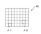
- FIG. 1A is a diagram schematically showing an example of a filter array.
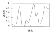
- FIG. 1B is a diagram showing an example of a transmission spectrum of a first filter among the multiple filters included in the filter array of FIG. 1A.
- FIG. 1C is a diagram showing an example of a transmission spectrum of a second filter among the multiple filters included in the filter array of FIG. 1A.
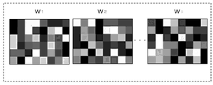
- FIG. 1D is a diagram schematically showing the relationship between a target wavelength range and multiple wavelength bands included therein.
- FIG. 1E is a diagram showing an example of spatial distribution of transmittance of light in each of the plurality of wavelength bands shown in FIG. 1D.
- FIG. 2 is a graph showing an example of transmission spectra of 4 types of filters out of 16 types of filters included in the filter array.
- FIG. 3 shows (a) the spectrum of reflected light and fluorescence of excitation light that occurs in conventional fluorescence imaging, (b) the transmission spectrum of a filter, and (c) the spectrum of reflected light and fluorescence of excitation light after transmission through the filter. It is a figure which shows a spectrum typically.
- FIG. 4 is a diagram schematically showing the configuration of an imaging device according to exemplary Embodiment 1 of the present disclosure.
- FIG. 5 is a graph showing the central wavelength dependence of the average transmittance when the filter is irradiated with excitation light having a rectangular spectrum.
- FIG. 6 shows (a) the spectrum of the reflected light and fluorescence of the excitation light generated in fluorescence imaging in Embodiment 1, (b) the transmission spectrum of the filter, and (c) the reflected light of the excitation light after passing through the filter and
- FIG. 4 is a diagram schematically showing a spectrum of fluorescence;
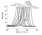
- FIG. 7 is a graph showing examples of absorption spectra of nine common fluorescent dyes.
- 8A shows (a) the spectrum of reflected light and fluorescence of excitation light that occurs in fluorescence imaging in Embodiment 1, (b) the transmission spectrum of filter 1, (c) the transmission spectrum of filter 2, and (d) the spectrum of filter 3. It is a figure which shows a transmission spectrum typically.
- FIG. 8B is a diagram schematically showing (a) the spectrum of reflected light and fluorescence of excitation light that occurs in fluorescence imaging in Embodiment 1, (b) the transmission spectrum of filter 4, and (c) the transmission spectrum of filter 5.
- FIG. 9A is a graph showing the absorption spectrum of Cy3.
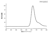
- FIG. 9B is a graph showing the fluorescence spectrum of Cy3.
- FIG. 10A is a graph showing the absorption spectrum of Cy5.
- FIG. 10B is a graph showing the fluorescence spectrum of Cy5.
- FIG. 11 is a diagram schematically showing the configuration of an imaging device according to exemplary Embodiment 2 of the present disclosure.
- FIG. 12A is a graph showing the absorption spectrum of Cy5.5.
- FIG. 12B is a graph showing the fluorescence spectrum of Cy5.5.
- FIG. 13 is a diagram schematically showing (a) the spectrum of the excitation light from the first LED, (b) the spectrum of the excitation light from the second LED, and (c) the spectrum of
- all or part of a circuit, unit, device, member or section, or all or part of a functional block in a block diagram is, for example, a semiconductor device, a semiconductor integrated circuit (IC), or an LSI (large scale integration). ) may be performed by one or more electronic circuits.
- An LSI or IC may be integrated on one chip, or may be configured by combining a plurality of chips.
- functional blocks other than memory elements may be integrated into one chip.
- LSIs or ICs may be called system LSIs, VLSIs (very large scale integration), or ULSIs (ultra large scale integration) depending on the degree of integration.
- a Field Programmable Gate Array (FPGA), which is programmed after the LSI is manufactured, or a reconfigurable logic device that can reconfigure the connection relationships inside the LSI or set up the circuit partitions inside the LSI can also be used for the same purpose.
- FPGA Field Programmable Gate Array
- circuits, units, devices, members or parts can be executed by software processing.
- the software is recorded on one or more non-transitory storage media, such as ROMs, optical discs, hard disk drives, etc., such that when the software is executed by a processor, the functions specified in the software are performed. It is executed by processors and peripherals.
- a system or apparatus may include one or more non-transitory storage media on which software is recorded, a processor, and required hardware devices such as interfaces.
- fluorescence imaging may be switched to normal transmission imaging or reflection imaging.
- normal transmission image photography or reflection image photography a light image in which fluorescence and reflected light of excitation light are superimposed is obtained. In this case, it is necessary to remove the optical element that cuts off the excitation light or replace the optical element with a half mirror for normal transmission image capturing or reflection image capturing.
- a hyperspectral imaging device capable of obtaining hyperspectral images can also be used for fluorescence imaging.
- a hyperspectral image is image data that has more wavelength information than a typical RGB image.
- a hyperspectral image shows an image for each of the four or more wavelength bands contained in the wavelength range of interest.
- fluorescence imaging when the fluorescence spectrum has a wavelength range that does not overlap with the spectrum of the reflected light of the excitation light, in the wavelength band included in the wavelength range, a fluorescence image can be obtained without removing the reflected light of the excitation light. can be done. Therefore, there is no need to use an optical element that blocks excitation light, and there is no need to change the optical element for each type of fluorescent dye.
- the hyperspectral imaging devices used for fluorescence imaging include a line-scanning hyperspectral camera and a camera with a liquid crystal tunable filter.
- a line-shaped reflected light image is obtained by irradiating an object with line-shaped light. Each band is separated into line-shaped images.
- a hyperspectral image of the object can be obtained by scanning the illumination position of the object with line-shaped light and sequentially capturing the images. Since scanning takes time, it is not easy to capture moving images with a line-scanning hyperspectral camera.
- a camera with a liquid crystal tunable filter can change the wavelength band of light that passes through the filter according to the value of the voltage applied to the filter. By applying different values of voltage to the filter and imaging the object multiple times, a hyperspectral image of the object is obtained.
- White-light transmission and reflection images are used for overall observation of an object. In a liquid crystal tunable filter, it is not easy to achieve a state of white transmission.
- a hyperspectral image can also be obtained using the compressed sensing technique disclosed in Patent Document 1.
- an image sensor detects light reflected by an object through a coded filter array called a coded element.
- the filter array includes a plurality of filters arranged two-dimensionally. Each of these filters has a unique transmission spectrum. Imaging using such a filter array yields a compressed image in which image information of a plurality of bands is compressed as one two-dimensional image.
- the spectral information of the object is compressed and recorded as one pixel value for each pixel.
- FIG. 1A is a diagram schematically showing an example of the filter array 40.
- FIG. Filter array 40 includes a plurality of filters arranged two-dimensionally. Each filter has an individually set transmission spectrum. The transmission spectrum is represented by a function T( ⁇ ), where ⁇ is the wavelength of incident light. The transmission spectrum T( ⁇ ) can take a value of 0 or more and 1 or less.
- the filter array 40 has 48 rectangular filters arranged in 6 rows and 8 columns. This is only an example and in actual applications more filters may be provided. The number of filters included in the filter array 40 may be approximately the same as the number of pixels of the image sensor.
- FIG. 1B and 1C are diagrams showing examples of transmission spectra of the first filter A1 and the second filter A2, respectively, among the plurality of filters included in the filter array 40 of FIG. 1A.
- the transmission spectrum of the first filter A1 and the transmission spectrum of the second filter A2 are different from each other.
- the transmission spectrum of filter array 40 differs depending on the filter. However, it is not necessary that all filters have different transmission spectra.
- the filter array 40 at least two filters out of the plurality of filters have different transmission spectra. That is, the filter array 40 includes two or more filters with different transmission spectra.
- the number of transmission spectral patterns of the plurality of filters included in filter array 40 can be equal to or greater than the number i of wavelength bands included in the wavelength band of interest.
- Filter array 40 may be designed such that more than half of the filters have different transmission spectra.
- FIG. 1D is a diagram schematically showing the relationship between a target wavelength range W and a plurality of wavelength bands W 1 , W 2 , . . . , W i included therein.
- the target wavelength band W can be set in various ranges depending on the application.
- the target wavelength range W can be, for example, a visible light wavelength range from about 400 nm to about 700 nm, a near-infrared wavelength range from about 700 nm to about 2500 nm, or a near-ultraviolet wavelength range from about 10 nm to about 400 nm.
- the target wavelength range W may be a mid-infrared or far-infrared wavelength range.
- the wavelength range used is not limited to the visible light range. In this specification, not only visible light but also electromagnetic waves with wavelengths outside the visible light wavelength range, such as ultraviolet rays and near-infrared rays, are referred to as "light" for convenience.
- i is an arbitrary integer equal to or greater than 4, and the respective wavelength ranges obtained by equally dividing the target wavelength range W into i are defined as bands W 1 , W 2 , . . . , W i .
- a plurality of bands included in the target wavelength band W may be set arbitrarily.
- the bands may have uneven widths. There may be gaps between adjacent bands. If the number of bands is four or more, more information can be obtained from the hyperspectral image than from the RGB image.
- FIG. 1E is a diagram showing an example of the spatial distribution of light transmittance in each of the plurality of wavelength bands W 1 , W 2 , . . . , W i shown in FIG. 1D.
- the difference in shade of each filter represents the difference in light transmittance.
- a lighter filter has a higher transmittance, and a darker filter has a lower transmittance.
- the spatial distribution of light transmittance differs depending on the wavelength band.
- a filter array 40 that is actually used includes, for example, one million filters.
- the one million filters include, for example, 16 types of filters that are two-dimensionally arranged randomly or quasi-randomly.
- a definition of random and quasi-random is given in US Pat.
- FIG. 2 is a graph showing an example of transmission spectra of 4 types of filters out of 16 types of filters included in the filter array 40.
- the transmission spectrum of each filter has multiple transmission peaks within the wavelength range of interest from 450 nm to 550 nm. For two adjacent transmission peaks, the peak wavelength spacing is about 50 nm.
- Each transmission peak has a maximum transmittance of 90% or more and a half width of about 10 nm.
- transmission peak means a convex shape containing a maximum in a transmission spectrum
- peak wavelength means a wavelength corresponding to a maximum contained in a convex shape in a spectrum.
- a transmission spectrum as shown in FIG. 2 can be realized, for example, by a filter including two dielectric multilayer films and a transparent layer positioned therebetween.
- a dielectric multilayer film has a wavelength band with high reflectance called a stop band.
- a standing wave is formed in the transparent layer located between the two dielectric multilayer films, and as a result, multiple transmission peaks appear in the stopband wavelength region.
- multiple transmission peaks can be shifted along the wavelength axis.
- a hyperspectral image can be restored from a compressed image using data indicating the spatial distribution of light transmittance for each wavelength band in the filter array 40 .
- Compressive sensing techniques are used for reconstruction.
- Data indicating the spatial distribution of light transmittance for each wavelength band in the filter array, which is used in the restoration process, is called a "restoration table.”
- the restoration table is determined based on the spatial distribution of the transmission spectra of the multiple types of filters included in the filter array 40 .
- Compressive sensing technology does not require the use of a spectroscopic element such as a prism or a grating, so the size of the imaging device can be reduced.
- compressed images can reduce the amount of data to process.
- the compressed image data g, the restoration table H, and the hyperspectral image data f acquired by the image sensor satisfy the following formula (1).
- the compressed image data g and the hyperspectral image data f are vector data
- the restoration table H is matrix data. Assuming that the number of pixels of the compressed image data g is Ng, the compressed image data g is expressed as a one-dimensional array or vector having Ng elements. Assuming that the number of pixels of the hyperspectral image data f is N f and the number of wavelength bands is M, the hyperspectral image data f is expressed as a one-dimensional array or vector having N f ⁇ M elements.
- the reconstruction table H is represented as a matrix with N g rows (N f ⁇ M) columns of elements. N g and N f can be designed to the same value.
- f' represents the estimated data of f.
- the first term in parentheses in the above formula represents the amount of deviation between the estimation result Hf and the acquired data g, ie, the so-called residual term.
- the sum of squares is used as the residual term here, the absolute value or the square root of the sum of squares may be used as the residual term.
- the second term in parentheses is a regularization term or a stabilization term, which will be described later.
- Equation (2) means finding f that minimizes the sum of the first and second terms.
- the arithmetic processing circuit can converge the solution by recursive iterative arithmetic and calculate the final solution f.
- the first term in the parenthesis of formula (2) means an operation for obtaining the sum of the squares of the difference between the obtained data g and Hf obtained by system-transforming f in the estimation process using the matrix H.
- the second term, ⁇ (f), is a constraint on the regularization of f, and is a function that reflects the sparse information of the estimated data. As a function, it has the effect of smoothing or stabilizing the estimated data.
- the regularization term may be represented by, for example, the Discrete Cosine Transform (DCT), Wavelet Transform, Fourier Transform, or Total Variation (TV) of f. For example, when the total variation is used, it is possible to acquire stable estimated data that suppresses the influence of noise in the observed data g.
- DCT Discrete Cosine Transform
- TV Total Variation
- the sparsity of an object in the space of each regularization term depends on the texture of the object.
- a regularization term may be chosen that makes the texture of the object more spars in the space of regularization terms.
- multiple regularization terms may be included in the operation.
- ⁇ is a weighting factor. The larger the weighting factor ⁇ , the larger the reduction amount of redundant data and the higher the compression ratio. The smaller the weighting factor ⁇ , the weaker the convergence to the solution.
- the weighting factor ⁇ is set to an appropriate value with which f converges to some extent and does not become over-compressed.
- Patent Document 1 A more detailed method of obtaining hyperspectral images by the technique of compressed sensing is disclosed in Patent Document 1. The entire disclosure of Patent Document 1 is incorporated herein by reference.
- a laser light source is often used to excite fluorescence.
- the spectrum width of laser light emitted from a laser light source is about several nanometers.
- mercury lamps are often used rather than laser light sources.
- the spectral width of light emitted from a mercury lamp is also about the same as or narrower than the spectral width of laser light.
- the half width of the transmission peak of each filter is about 10 nm, and the transmittance of the transmission peak of each filter is 90% or more. .
- FIG. 3 shows (a) the reflected light and fluorescence spectra of excitation light that occur in conventional fluorescence imaging, (b) the transmission spectrum of a filter (referred to as filter P), and (c) the filter (i.e., filter P).
- FIG. 4 is a diagram schematically showing reflected light and fluorescence spectra of excitation light after transmission.
- the spectrum of the reflected light of the excitation light has the same shape as the spectrum of the excitation light, except for the difference in intensity.
- the reflected light of the excitation light has relatively high intensity and the fluorescence has relatively low intensity.
- the spectral width of the reflected light of the excitation light is relatively narrow, and the spectral width of the fluorescence is relatively wide.
- the transmission spectrum of filter P has two transmission peaks.
- the peak wavelength of the transmission peak located on the low wavelength side matches the peak wavelength of the reflected light of the excitation light.
- the peak wavelength of the transmission peak located on the high wavelength side corresponds to the wavelength of the highest fluorescence intensity.
- the spectral width of the reflected excitation light is almost unchanged before and after passing through the filter P, and the spectral width of the fluorescence is narrow after passing through the filter P.
- the dashed line shown in (c) of FIG. 3 represents the fluorescence spectrum shown in (a) of FIG.
- the filter array 40 includes multiple types of filters with different transmission spectra so that various spectra can be restored. If the peak wavelength of the excitation light is changed, the transmittance of the reflected light of the excitation light through the filter will be low for some filters but high for other filters. That is, even if the peak wavelength of the excitation light is changed, the reflected light of the excitation light is transmitted through any one of the filters with high efficiency.
- the fluorescence intensity is lower than the excitation light intensity, as shown in (a) of FIG.
- the excitation light intensity is increased to the extent that sufficiently high fluorescence intensity is obtained, the reflected light of the excitation light is efficiently transmitted through the filter, and luminance saturation often occurs in pixels corresponding to the filter.
- luminance is saturated, the information necessary for the restoration operation described above is missing, and an accurate hyperspectral image may not be obtained.
- the present inventor has conceived of an imaging device that can more accurately generate a hyperspectral image using compression sensing technology in fluorescence imaging.
- the filter array includes at least two filters with different transmission spectra, and the spectrum of the excitation light overlaps the transmission regions of the transmission spectra of at least the two filters.
- a transmitted component of the reflected light of the excitation light transmitted through the filter array is distributed to at least the two filters.
- luminance saturation can be suppressed in pixels corresponding to each filter, and a hyperspectral image can be generated more accurately.
- the imaging device includes at least one light source that emits excitation light for illuminating an object that includes at least one light emitter, a coded filter array that includes a plurality of filters having different transmission spectra, An image sensor that captures object light generated by irradiation of the excitation light through the encoding filter array and generates compressed image data, and a processing circuit that generates hyperspectral image data based on the compressed image data.
- the object light includes emitted light generated by absorption of the excitation light by the at least one luminous body and reflected light of the excitation light reflected by the object.
- the plurality of filters includes two filters having different transmission spectra. The spectrum of the excitation light overlaps the transmission regions of the transmission spectra of the two filters.
- luminance saturation can be suppressed in pixels corresponding to each filter, and a hyperspectral image can be generated more accurately.
- the imaging device is the imaging device according to the first item, wherein the two filters include a first filter.
- the wavelength range having an intensity equal to or greater than half the maximum intensity in the spectrum of the excitation light includes a wavelength range having an intensity equal to or greater than half the maximum intensity at the first transmission peak in the transmission spectrum of the first filter.
- the spectrum of the excitation light can be superimposed on the transmission regions of the transmission spectra of the two filters.
- the imaging device is the imaging device according to the first item, wherein the two filters include a first filter, and the half width of the spectrum of the excitation light is the second filter in the transmission spectrum of the first filter. It is wider than the half-value width of one transmission peak.
- the spectrum of the excitation light can be superimposed on the transmission regions of the transmission spectra of the two filters.
- An imaging device is the imaging device according to the first item, wherein the two filters are a first filter and a second filter, and the spectrum of the excitation light is the transmission spectrum of the first filter. A first transmission peak and a second transmission peak in the transmission spectrum of the second filter overlap.
- the spectrum of the excitation light can be superimposed on the transmission regions of the transmission spectra of the two filters.
- An imaging device is the imaging device according to any one of the first to fourth items, wherein the spectrum of the excitation light has a wavelength region that overlaps the absorption spectrum of the at least one light emitter, The emission spectrum of the at least one light emitter has a wavelength range that does not overlap the spectrum of the reflected light of the excitation light.
- the luminous body can be excited by the excitation light, and the emission spectrum of the luminous body does not overlap the spectrum of the reflected light of the excitation light. It is possible to obtain an object beam that does not contain
- the imaging device is the imaging device according to any one of the first to fifth items, wherein the light source includes an LED or a superluminescent diode.
- excitation light with a broad spectrum can be emitted from the light source.
- An imaging device is the imaging device according to any one of the first to sixth items, wherein the at least one light source comprises a first light source that emits first excitation light and a second excitation light that emits second excitation light. and a second light source that emits.
- the spectrum of the first excitation light and the spectrum of the second excitation light are different from each other.
- the processing circuit switches between an operation of causing the first light source to emit the first excitation light and an operation of causing the second light source to emit the second excitation light.
- the object can be illuminated with the first excitation light or the second excitation light depending on the application.
- the imaging device is the imaging device according to the seventh item, wherein the at least one light emitter includes a first light emitter and a second light emitter.
- the first absorption spectrum of the first light emitter and the second absorption spectrum of the second light emitter are different from each other.
- the first excitation light is light capable of exciting the first light emitter.
- the second excitation light is light capable of exciting the second light emitter.
- the imaging device according to the ninth item is the imaging device according to the seventh item, wherein the first excitation light is white light, and the second excitation light can excite the at least one luminous body. It is the light that is.
- the first excitation light can be used to observe a transmitted image and/or a reflected image
- the second excitation light can be used to observe a fluorescent image
- FIG. 4 is a diagram schematically showing the configuration of the imaging device 100 according to exemplary Embodiment 1 of the present disclosure.
- FIG. 4 shows an object 10 containing different fluorescent dyes.
- the number of types of fluorescent dyes may be one.
- a substance that absorbs excitation light and produces emission light is referred to herein as a "emitter.” If the emitter is a fluorochrome, the emitted light is fluorescence.
- the emitters may be phosphorescent dyes or quantum dots instead of fluorescent dyes.
- the imaging device 100 shown in FIG. 4 includes a light source 20 , an optical system 30 , a filter array 40 , an image sensor 50 , and a processing circuit 60 that controls the light source 20 and the image sensor 50 .
- the light source 20 emits excitation light 20L 1 for illuminating the object 10 . Illuminating the object 10 with the excitation light 20L 1 results in an object light 20L 2 .
- the object light 20L 2 includes fluorescence emitted by the fluorescent dye absorbing part of the excitation light 20L 1 and reflected light of the excitation light 20L 1 reflected by the object 10 .
- the excitation light 20L 1 can excite the fluorochrome if the spectrum of the excitation light 20L 1 has a wavelength region that overlaps the absorption spectrum of the fluorochrome.
- the phrase "the spectrum of X has a wavelength range overlapping the spectrum of Y” means that the wavelength range of the spectrum of X includes at least part of the wavelength range of the spectrum of Y.
- spectrum wavelength range means a wavelength range having an intensity of 1/10 or more of the maximum intensity in the spectrum.
- Spectrum width means the width of the wavelength band. However, in the following description, depending on the case, the half width of the spectrum may be used instead of the spectrum width.
- the spectrum of the excitation light overlaps with the transmission region of the transmission spectrum of the filter means that "the wavelength region showing an intensity of 1/10 or more of the maximum intensity in the spectrum of the excitation light is the maximum transmittance in the transmission spectrum of the filter. It may also mean that it overlaps with a wavelength region having a transmittance of 1/10 or more.
- X spectrum has a wavelength range that does not overlap with Y spectrum means that the wavelength range of X spectrum has a portion that is not included in the wavelength range of Y spectrum.
- Optical system 30 includes at least one lens. Although shown as one lens in FIG. 4, the optical system 30 may be configured by a combination of a plurality of lenses. The optical system 30 forms an image of the object light 20L2 on the imaging surface of the image sensor 50 via the filter array 40. FIG.
- the filter array 40 is as described with reference to FIGS. 1A to 2.
- Filter array 40 may be placed near or directly above image sensor 50 .
- Near means that the image of the light from the optical system 30 is close enough to be formed on the surface of the filter array 40 in a somewhat clear state.
- Directly above means that they are so close to each other that there is almost no gap.
- Filter array 40 and image sensor 50 may be integrated.
- the image sensor 50 includes a plurality of pixels arranged two-dimensionally, that is, a pixel array, and generates and outputs compressed image data according to the intensity of light incident on the pixel array.
- a plurality of filters included in the filter array 40 may correspond to a plurality of pixels included in the image sensor 50, respectively. That is, each of the multiple filters corresponds to one of the multiple pixels. However, the plurality of filters does not necessarily have to correspond to the plurality of pixels on a one-to-one basis.
- the processing circuit 60 causes the light source 20 to emit the excitation light 20L1 . Based on the compressed image data generated and output by the image sensor 50 and the decompression table, the processing circuitry 60 generates and outputs hyperspectral image data representing an image for each of the plurality of wavelength bands. The method of generating hyperspectral image data is as described above.
- a computer program executed by the processing circuit 60 is stored in a memory (not shown) such as ROM or RAM (Random Access Memory).
- the imaging device 100 includes a processing unit including processing circuitry 60 and memory.
- the processing circuitry 60 and memory may be integrated on one circuit board or provided on separate circuit boards.
- the functionality of processing circuitry 60 may be distributed over multiple circuitry.
- the restoration table may be stored in the memory described above.
- the average transmittance T satisfies the following formula.
- ⁇ is the wavelength
- I( ⁇ ) is the spectrum of the irradiation excitation light
- t( ⁇ ) is the spectral transmission spectrum of the filter.
- ⁇ indicates integration over the entire wavelength range, substantially the wavelength range where the filter is not zero.
- the actual excitation light 20L1 often has a Gaussian function-shaped spectrum
- the half-value width dependence of the average transmittance is similar between the rectangular-shaped spectrum and the Gaussian-function-shaped spectrum. Therefore, a description will be given here using a rectangular spectrum.
- a rectangular excitation light spectrum can be represented by a center wavelength and a half width.
- FIG. 5 is a graph showing the center wavelength dependence of the average transmittance when the filter is irradiated with excitation light having a rectangular spectrum.
- the half width is 5.2 nm
- the value at 510 nm on the horizontal axis is the transmittance when light having an intensity distribution in the wavelength range of 507.4 nm to 512.6 nm is irradiated.
- the value at 515 nm on the horizontal axis for the value width of 5.2 nm is the transmittance when irradiated with light having an intensity distribution in the wavelength range of 512.4 nm to 517.6 nm.
- FIG. 5 is a graph showing the center wavelength dependence of the average transmittance when the filter is irradiated with excitation light having a rectangular spectrum.
- RAW indicates the average transmittance when the filter is irradiated with excitation light having a spectrum with a half-value width of approximately 0, and 5.2 nm indicates the filter with excitation light having a spectrum with a half-value width of 5.2 nm.
- 9.6 nm indicates the average transmittance when the filter is irradiated with excitation light having a spectrum with a half-value width of 9.6 nm, and 18.4 nm indicates a spectrum with a half-value width of 18.4 nm.
- 27.3 nm indicates the average transmittance when the filter is irradiated with excitation light having a spectrum with a half-value width of 27.3 nm
- 36.1 nm indicates the average transmittance when the filter is irradiated with excitation light having a spectrum of 27.3 nm.
- the average transmittance when the filter is irradiated with excitation light having a spectrum with a value width of 36.1 nm is shown.
- the peak indicating the relationship between the center wavelength of the excitation light 20L1 and the average transmittance is the transmission peak of the filter. match.
- the peak shown in FIG. 5 becomes broader and the highest average transmittance decreases. If the spectral half-width of the excitation light 20L 1 is narrower or comparable to the half-width of the transmission peak of the filter, i.e. RAW (approximately 0 nm), 5.2 nm and 9.6 nm, the highest average transmission is 80% or more.
- the maximum average transmission is 80 % and decreases significantly.
- the half-value width of the spectrum of the excitation light 20L1 is about twice the half-value width of the transmission peak of the filter, that is, 18.4 nm, the maximum average transmittance is 60% or less. If the half-value width of the spectrum of the excitation light 20L1 is about three times the half-value width of the transmission peak of the filter, ie, 27.3 nm, the maximum average transmittance will be 50% or less.
- the spectrum of the excitation light 20L 1 can be selected as follows. That is, the wavelength region (referred to as the “first wavelength band”) having an intensity equal to or greater than half the maximum intensity in the spectrum of the excitation light 20L1 is the wavelength region having an intensity equal to or greater than half the maximum intensity at the transmission peak of the filter (“ (referred to as the second wavelength band)).
- the minimum wavelength value included in the first wavelength band is smaller than the minimum wavelength value included in the second wavelength band
- the maximum wavelength value included in the first wavelength band is the maximum wavelength value included in the second wavelength band. bigger than In this case, the half-value width of the spectrum of the excitation light 20L1 is wider than the half-value width of the transmission peak of the filter.
- the highest average transmittance decreases as shown in FIG. 5, and luminance saturation in pixels can be suppressed.
- the spectrum of the excitation light 20L 1 is broad means that the half width of the spectrum of the excitation light 20L 1 is wider than the half width of the transmission peak of the filter.
- FIG. 6 shows (a) the spectrum of the reflected light and fluorescence of the excitation light 20L 1 that occurs in fluorescence imaging in Embodiment 1, (b) the transmission spectrum of the filter (referred to as filter Q), and (c) the filter (that is, FIG. 4 is a diagram schematically showing spectra of reflected light 20L1 of excitation light and fluorescence after passing through a filter Q).
- the spectrum of the reflected light of the excitation light 20L1 shown in (a) of FIG. is lower.
- the fluorescence spectrum shown in (a) of FIG. 6 has substantially the same spectral width and the maximum intensity of the spectrum as compared with the fluorescence spectrum shown in (a) of FIG.
- FIG. 7 is a graph showing examples of absorption spectra of nine common fluorescent dyes.
- the half width of the absorption spectrum of each fluorescent dye is 30 nm or more and 50 nm or less. If the half width of the spectrum of the excitation light 20L 1 is wider than the half width of the absorption spectrum of the fluorescent dye, the fluorescent dye can be excited by the excitation light 20L 1 with high efficiency.
- the half-width of the absorption spectrum of each fluorochrome is wider than the half-width of the transmission peak of the filter.
- the half-value width of the spectrum of the excitation light 20L 1 is selected to be wider than the half-value width of the absorption spectrum of the fluorescent dye, the half-value width of the spectrum of the excitation light 20L 1 is necessarily wider than the half-value width of the transmission peak of the filter. get wider.
- the fluorescent dye can be excited with high efficiency, and the average transmittance of the reflected light of the excitation light after passing through the filter can be reduced.
- a high fluorescence intensity can be obtained by exciting the fluorescent dye with high efficiency.
- By lowering the average transmittance of the reflected light of the excitation light it is possible to suppress the luminance saturation in the pixels. From the above, a hyperspectral image can be generated more accurately.
- Fluorescence intensity is strongly dependent on the number of photons excited within the fluorochrome and less dependent on the wavelength of the excited photons. Therefore, even if the half width of the spectrum of the excitation light 20L1 is widened to reduce the intensity of the excitation light 20L1 per unit wavelength, high fluorescence intensity can be obtained. This property is also effective in reducing the average transmittance of the excitation light 20L1 passing through the filter.
- the filter array 40 includes multiple types of filters with different transmission spectra. Any kind of filter has a certain or more transmittance in any wavelength band so that an image for each of a plurality of wavelength bands can be obtained.
- the transmission component of the reflected light of the excitation light 20L 1 transmitted through the filter array 40 is necessarily In addition, rather than concentrating on only one filter included in filter array 40, it is distributed to other filters included in filter array 40 as well. As a result, the transmitted component of the reflected light of the excitation light 20L1 is distributed to a plurality of filters, and it is possible to suppress saturation of luminance in pixels corresponding to one filter included in the filter array 40 .
- FIGS. 8A and 8B show (a) the spectrum of reflected light and fluorescence of excitation light that occurs in fluorescence imaging in Embodiment 1, (b) the transmission spectrum of filter 1, (c) the transmission spectrum of filter 2, and (d) the spectrum of filter 3. It is a figure which shows a transmission spectrum typically. A region sandwiched by two vertical dashed lines shown in FIG. 8A represents the wavelength region of the spectrum of the reflected light of the excitation light 20L1 . The transmission spectrum of each filter exhibits multiple transmission peaks.
- the transmission peak with filter 2 overlaps a portion of the transmission peak with filter 1 and a portion of the transmission peak with filter 3 .
- the transmission peak overlap can be defined by the wavelength range of the transmission peaks. "A certain transmission peak overlaps a part of another transmission peak” means that the wavelength range of a certain transmission peak includes a part of the wavelength range of the other transmission peak. “Wavelength range of transmission peak” means a wavelength range having a transmittance of 1/10 or more of the maximum transmittance at the transmission peak.
- the reflected light of excitation light 20L1 is distributed to filter 1 , filter 2, and filter 3.
- the spectrum of the reflected light of excitation light 20L 1 overlaps part of the transmission peak with filter 1, all of the transmission peak with filter 2, and part of the transmission peak with filter 3.
- the spectrum of X overlaps a portion of the transmission peak of the filter means that the spectral wavelength range of X includes a portion of the wavelength range of the transmission peak of the filter.
- the spectrum of X overlaps the entire transmission peak of the filter means that the spectral wavelength range of X includes the entire wavelength range of the transmission peak of the filter.
- the spectrum of X overlaps the transmission peak of the filter means that the spectrum of X overlaps some or all of the transmission peak of the filter.
- FIG. 8B is a diagram schematically showing (a) the spectrum of reflected light and fluorescence of excitation light that occurs in fluorescence imaging in Embodiment 1, (b) the transmission spectrum of filter 4, and (c) the transmission spectrum of filter 5.
- the transmission peaks with filter 4 and the transmission peaks with filter 5 partially overlap each other.
- the reflected light of excitation light 20L1 is distributed to filters 4 and 5.
- the spectrum of the reflected light of excitation light 20L 1 overlaps part of the transmission peak with filter 4 and part of the transmission peak with filter 5 .
- the spectrum of the reflected light of excitation light 20L 1 need not overlap all of one transmission peak of one filter included in filter array 40 .
- the spectrum of the reflected light of excitation light 20L1 overlaps the transmission peaks of at least two filters.
- the plurality of types of filters in the filter array 40 include at least two filters with different transmission spectra, and the spectrum of the excitation light 20L1 is at least that of the two filters. It overlaps with the transmission region in the transmission spectrum.
- a "transmission range in a transmission spectrum” means a wavelength range of a certain transmission peak in a transmission spectrum.
- a transmitted component of the reflected light of the excitation light 20L1 transmitted through the filter array 40 is distributed to at least the two filters. Of the reflected light of the excitation light 20L1, the average transmittance of the portion that passes through each filter can be, for example, 5% or more and 60% or less.
- the object 10 contains multiple types of fluorescent dyes and the spectrum of the reflected light of the excitation light 20L1 overlaps the fluorescence spectrum of each type of fluorescent dye, it is not easy to identify the fluorescent dyes by observing the fluorescence.
- the spectrum of the excitation light 20L1 may be appropriately selected such that the fluorescence spectrum has a wavelength range that does not overlap the spectrum of the reflected light of the excitation light 20L1 .
- FIGS. 9A to 10B are graphs showing the absorption spectrum and fluorescence spectrum of Cy3, respectively.
- 10A and 10B are graphs showing the absorption spectrum and fluorescence spectrum of Cy5, respectively.
- the absorption spectra of Cy3 and Cy5 have effective absorbance in the wavelength range of 500 nm or more and 600 nm or less. Therefore, when the wavelength range of the spectrum of the excitation light 20L1 is 500 nm or more and 600 nm or less, the excitation light 20L1 can excite both at the same time.
- the wavelength range of the spectrum of the excitation light 20L1 is 500 nm or more and 600 nm or less.
- the fluorescence spectrum of Cy3 has effective fluorescence intensity in the wavelength range of 550 nm or more and 650 nm or less.
- the fluorescence spectrum does not overlap the absorption spectrum in the wavelength range of 600 nm or more and 650 nm or less. Therefore, by irradiating the object 10 with the excitation light 20L1, it is possible to obtain the object light 20L2 that contains fluorescence in the wavelength range of 600 nm or more and 650 nm or less but does not contain the reflected light of the excitation light 20L1 .
- the fluorescence spectrum of Cy5 has effective fluorescence intensity in the wavelength range of 625 nm or more and 750 nm or less.
- the fluorescence spectrum does not overlap the absorption spectrum in the wavelength range of 700 nm or more and 750 nm or less. Therefore, by irradiating the object 10 with the excitation light 20L1, it is possible to obtain the object light 20L2 that contains fluorescence in the wavelength range of 700 nm or more and 750 nm or less but does not contain the reflected light of the excitation light 20L1 .
- a fluorescence image of Cy3 can be obtained in a wavelength band included in the wavelength range of 600 nm or more and 625 nm or less, and a fluorescence image of Cy5 can be obtained in a wavelength band included in the wavelength range of 625 nm or more and 750 nm or less.
- a fluorescence image can be obtained.
- the wavelength range of the fluorescence spectrum differs for each type of fluorescent dye. Therefore, the light source 20 may be changed for each type of fluorescent dye.
- the spectrum of the excitation light 20L1 has a high intensity in a specific wavelength range, and its half width can be, for example, 20 nm or more and 50 nm or less.
- a light source 20 emitting such excitation light 20L 1 may include, for example, an LED or a superluminescent diode.
- light source 20 may include a white light source that emits white light and an optical element that blocks part of the spectrum of the white light.
- the white light source can be, for example, a halogen lamp, and the optical element can be, for example, a bandpass filter or a dichroic mirror.
- the optical element blocks at least a portion of the components of the spectrum of white light in a wavelength range that overlaps the spectrum of fluorescence.
- FIG. 11 is a diagram schematically showing the configuration of an imaging device 200 according to exemplary Embodiment 2 of the present disclosure.
- FIG. 11 shows an object 10 containing multiple types of fluorescent dyes.
- the imaging device 200 shown in FIG. 11 includes a first light source 20a, a second light source 20b, an optical element 21, an irradiation optical system 22, an optical system 30, a filter array 40, an image sensor 50, and a first light source. 20 a , a second light source 20 b , and processing circuitry 60 for controlling the image sensor 50 .
- the imaging device 200 shown in FIG. 11 differs from the imaging device 100 shown in FIG. 4 in that the imaging device 200 is not the light source 20 shown in FIG. It is provided with the element 21 and the irradiation optical system 22 .
- the number of light sources shown in FIG. 11 is two, it may be three or more depending on the purpose and application.
- the first light source 20a emits a first excitation light 20L1a .
- the second light source 20b emits a second excitation light 20L1b .
- the spectrum of the first excitation light 20L1a and the spectrum of the second excitation light 20L1b are different from each other. As in Embodiment 1, both spectra are broad. The meaning of broad is as explained in the first embodiment.
- the first excitation light 20L 1a is light that can excite a first fluorochrome that is a type of fluorochrome contained in the object 10 .
- the second excitation light 20L1b is light that can excite the second fluorochrome that is another type of fluorochrome contained in the object 10 .
- the absorption spectrum of the first fluorochrome and the absorption spectrum of the second fluorochrome are different from each other.
- the fluorescence spectrum of the first fluorochrome and the fluorescence spectrum of the second fluorochrome are different from each other.
- the first object light 20L- 2a consists of the first fluorescence emitted by the first fluorescent dye contained in the object 10 absorbing the first excitation light 20L- 1a and the reflected light of the first excitation light 20L- 1a reflected by the object 10. including.
- illuminating the object 10 with a second excitation light 20L 1b results in a second object light 20L 2b .
- the second object light 20L- 2b consists of the second fluorescence emitted by the second fluorescent dye contained in the object 10 after absorbing the second excitation light 20L- 1b and the reflected light of the second excitation light 20L- 1b reflected by the object 10. including.
- the optical element 21 passes the first excitation light 20L 1 a toward the irradiation optical system 22 and reflects the second excitation light 20 L 1 b toward the irradiation optical system 22 .
- Optical element 21 can be, for example, a dichroic mirror or a half mirror.
- the illumination optical system 22 illuminates the object 10 with the first excitation light 20L1a or the second excitation light 20L1b .
- Illumination optics 22 may include, for example, at least one of a lens, a curved mirror, or a light diffuser.
- the processing circuit 60 switches between a first operation of causing the first light source 20a to emit the first excitation light 20L- 1a and a second operation of causing the second light source 20b to emit the second excitation light 20L- 1b .
- No mechanical drive is required to switch between the first and second motions.
- the imaging apparatus 200 according to the second embodiment can emit excitation light suitable for multiple types of fluorescent dyes contained in the object 10 by switching between the first operation and the second operation.
- the object 10 includes Cy5.5 in addition to Cy3 and Cy5 described above.
- a combination of Cy3, Cy5, and Cy5.5 fluorochromes is common, for example, in m-FISH methods utilized for genetic testing.
- said first fluorochrome is Cy3 or Cy5 and said second fluorochrome is Cy5.5.
- FIG. 12A and 12B are graphs showing the absorption spectrum and fluorescence spectrum of Cy5.5, respectively.
- the absorption spectrum of Cy5.5 does not have effective absorbance in the wavelength range of 500 nm or more and 600 nm or less. Therefore, the excitation light whose spectrum has a wavelength range of 500 nm or more and 600 nm or less cannot efficiently excite Cy5.5, and the fluorescent image of Cy5.5 cannot be observed.
- the absorption spectrum of Cy5.5 has effective absorbance in the wavelength range of 600 nm or more and 700 nm or less.
- the fluorescence spectrum of Cy5.5 does not have significant fluorescence intensity at wavelengths shorter than 675 nm. If the excitation light has a spectral wavelength range of 600 nm or more and 675 nm or less, Cy5.5 can be efficiently excited and a fluorescence image of Cy5.5 can be observed. However, excitation light having a high intensity in the wavelength range cannot efficiently excite Cy3.
- the wavelength range of the spectrum of the first excitation light 20L1a is 500 nm or more and 600 nm or less
- the wavelength range of the spectrum of the second excitation light 20L1b is 600 nm or more and 675 nm or less.
- the imaging apparatus 200 In conventional fluorescence imaging, optical elements that block excitation light, such as dichroic mirrors or long-pass filters, are physically replaced for each type of fluorescent dye to be observed.
- switching between the first operation and the second operation is performed by electrical control of the processing circuit 60, so that many types of fluorescent elements can be observed at a higher speed. And the risk of physical damage such as wear can be reduced.
- the imaging device 200 according to the second embodiment can be easily installed in an imaging system with a limited physical size, such as an endoscope.
- the first excitation light 20L 1a may be used for observation of transmission images and/or reflection images
- the second excitation light 20L 1b may be used for observation of fluorescence images.
- the first excitation light 20L 1a is white light
- the second excitation light 20L 1b is light capable of exciting the fluorescent dye contained in the object 10.
- FIG. In the imaging device 200 according to the second embodiment the entire object 10 can be observed by observing the transmitted image and/or the reflected image of the object 10 by the first operation. Furthermore, by observing the fluorescent image through the second operation, a specific region within the object 10 can be emphasized.
- a reflected image using white light is effective for observing the stomach wall and/or the entire intestinal tract, and a fluorescent image obtained by accumulating a fluorescent dye in a tumor site and exciting the fluorescent dye. is effective in highlighting and identifying tumor sites.
- the first operation and the second operation can be switched at high speed. A fluorescence image can be obtained.
- FIG. 13 is a diagram schematically showing (a) the spectrum of the excitation light from the first LED, (b) the spectrum of the excitation light from the second LED, and (c) the spectrum of the excitation light with which the object is irradiated.
- a light source that emits excitation light with a broad spectrum can be configured by combining multiple light sources. For example, by simultaneously irradiating an object with excitation light from a plurality of light sources with different spectra, it can function as a broad light source.
- an object is simultaneously irradiated with excitation light from a first LED having a first spectrum 1301 as shown in FIG. 13(a) and excitation light from a second LED having a second spectrum 1302 as shown in FIG. 13(b).
- excitation light from a first LED having a first spectrum 1301 as shown in FIG. 13(a) and excitation light from a second LED having a second spectrum 1302 as shown in FIG. 13(b).
- the excitation light of the two LEDs may be applied to the object via separate optical systems.
- the excitation light from the two LEDs may be applied to the object after combining the respective light fluxes using a half mirror, a dichroic mirror, or the like.
- the first spectrum of the first LED and the second spectrum of the second LED may or may not overlap.
- three or more light sources having different spectra may be provided, and the combination of the light sources to be lit simultaneously may be changed according to the type of object.
- a light source that emits excitation light with a broad spectrum can be substantially configured by switching and lighting a plurality of light sources as described above.
- the image sensor 50 in the above-described embodiment normally outputs charges accumulated during a period called exposure time as a light reception signal. Therefore, the change in luminance of the incident light occurring within this exposure time is averaged into the received light signal. Therefore, by irradiating an object with excitation light from a plurality of light sources with different spectra while switching within the exposure time, it is possible to obtain substantially the same effect as irradiating the object with excitation light having an average spectrum of those spectra. can.
- a wavelength tunable light source such as a wavelength tunable laser, whose spectrum can be temporally changed may be used instead of the plurality of light sources described above.
- a wavelength tunable laser By changing the spectrum of the tunable laser within the exposure time, it is possible to obtain an effect equivalent to switching between a plurality of light sources.
- An imaging method according to an aspect of the present disclosure may be as described below.
- the imaging device 100 includes a memory that stores multiple instructions.
- Processing circuitry 60 includes one or more computers that retrieve and process the instructions.
- the plurality of commands include causing the light source 20 to emit excitation light.
- the excitation light illuminates the object 10
- the first light from the object 10 irradiated with the excitation light enters the filter array 40
- the first light enters the filter array 40.
- the second light enters the image sensor 50 .
- the first light includes third light output by the object absorbing part of the excitation light and fourth light resulting from reflection of part of the excitation light on the object 10 .
- the plurality of instructions include causing the processing circuitry 60 to generate a plurality of images corresponding to a plurality of wavelength regions based on the second light incident on the image sensor 50 .
- the filter array 40 includes a first filter and a second filter.
- All wavelengths corresponding to a first transmittance or more in the transmission spectrum of the first filter are included in the first range, and all wavelengths corresponding to a second transmittance or more in the transmission spectrum of the second filter is included in a second range, and the first range is different from the second range.
- the first spectrum of the excitation light has a rectangular shape, and all wavelengths corresponding to intensities greater than or equal to the first intensity in the first spectrum are included in the third range.
- a fourth range that is part of the third range overlaps part or all of the first area, and a fifth range that is part of the third range overlaps part or all of the second area. , the fourth range is different from the fifth range.
- the first transmittance is a value of 1/10 of the maximum transmittance in the transmission spectrum of the first filter
- the second transmittance is a value of 1/10 of the maximum transmittance in the transmission spectrum of the second filter.
- the first intensity may be 1/10 of the maximum intensity in the first spectrum.
- the technology of the present disclosure can be used, for example, in the biotechnology research field or the medical field for diagnosing cancer or intractable diseases.
Landscapes
- Engineering & Computer Science (AREA)
- Multimedia (AREA)
- Signal Processing (AREA)
- Physics & Mathematics (AREA)
- Spectroscopy & Molecular Physics (AREA)
- General Physics & Mathematics (AREA)
- Health & Medical Sciences (AREA)
- Nuclear Medicine, Radiotherapy & Molecular Imaging (AREA)
- Life Sciences & Earth Sciences (AREA)
- Chemical & Material Sciences (AREA)
- Analytical Chemistry (AREA)
- Biochemistry (AREA)
- General Health & Medical Sciences (AREA)
- Immunology (AREA)
- Pathology (AREA)
- Investigating, Analyzing Materials By Fluorescence Or Luminescence (AREA)
Priority Applications (3)
| Application Number | Priority Date | Filing Date | Title |
|---|---|---|---|
| CN202280031044.3A CN117321408A (zh) | 2021-05-20 | 2022-05-10 | 摄像装置 |
| JP2023522610A JPWO2022244645A1 (https=) | 2021-05-20 | 2022-05-10 | |
| US18/499,287 US12501123B2 (en) | 2021-05-20 | 2023-11-01 | Imaging apparatus |
Applications Claiming Priority (2)
| Application Number | Priority Date | Filing Date | Title |
|---|---|---|---|
| JP2021085319 | 2021-05-20 | ||
| JP2021-085319 | 2021-05-20 |
Related Child Applications (1)
| Application Number | Title | Priority Date | Filing Date |
|---|---|---|---|
| US18/499,287 Continuation US12501123B2 (en) | 2021-05-20 | 2023-11-01 | Imaging apparatus |
Publications (1)
| Publication Number | Publication Date |
|---|---|
| WO2022244645A1 true WO2022244645A1 (ja) | 2022-11-24 |
Family
ID=84140587
Family Applications (1)
| Application Number | Title | Priority Date | Filing Date |
|---|---|---|---|
| PCT/JP2022/019754 Ceased WO2022244645A1 (ja) | 2021-05-20 | 2022-05-10 | 撮像装置 |
Country Status (4)
| Country | Link |
|---|---|
| US (1) | US12501123B2 (https=) |
| JP (1) | JPWO2022244645A1 (https=) |
| CN (1) | CN117321408A (https=) |
| WO (1) | WO2022244645A1 (https=) |
Cited By (2)
| Publication number | Priority date | Publication date | Assignee | Title |
|---|---|---|---|---|
| WO2025142500A1 (ja) * | 2023-12-27 | 2025-07-03 | 国立大学法人奈良先端科学技術大学院大学 | 複数蛍光色素定量方法および装置 |
| WO2025249102A1 (ja) * | 2024-05-29 | 2025-12-04 | パナソニックIpマネジメント株式会社 | 撮像方法および撮像システム |
Citations (5)
| Publication number | Priority date | Publication date | Assignee | Title |
|---|---|---|---|---|
| JP2000097859A (ja) * | 1998-09-24 | 2000-04-07 | Olympus Optical Co Ltd | 蛍光観察方法及び装置 |
| JP2014531032A (ja) * | 2011-10-25 | 2014-11-20 | センター フォー スペース サイエンス アンド アプライド リサーチ、 チャイニーズ アカデミー オブ サイエンスズCenter For Space Science And Applied Research, Chinese Academy Of Sciences | 時間分解単一光子又は極微弱光多次元イメージングスペクトルシステム及び方法 |
| US20150105668A1 (en) * | 2013-10-15 | 2015-04-16 | Karl Storz Gmbh & Co. Kg | Endoscopic, Exoscopic Or Microscopic Apparatus For Fluorescence Diagnosis |
| JP2016156801A (ja) * | 2014-11-19 | 2016-09-01 | パナソニックIpマネジメント株式会社 | 撮像装置および分光システム |
| JP2019200208A (ja) * | 2018-05-17 | 2019-11-21 | カール・ツアイス・メディテック・アーゲー | プロトポルフィリンixを観察するためのフィルタセット、システムおよび方法 |
Family Cites Families (13)
| Publication number | Priority date | Publication date | Assignee | Title |
|---|---|---|---|---|
| JP4554944B2 (ja) | 2004-01-15 | 2010-09-29 | Hoya株式会社 | 内視鏡装置 |
| JP4971816B2 (ja) * | 2007-02-05 | 2012-07-11 | 三洋電機株式会社 | 撮像装置 |
| JP2009258618A (ja) * | 2008-03-27 | 2009-11-05 | Olympus Corp | フィルタ切替装置、撮影レンズ、カメラ、および撮影システム |
| KR101061004B1 (ko) * | 2008-12-10 | 2011-09-01 | 한국전기연구원 | 광역학 치료 및 광 검출을 위한 장치 |
| JP2010193421A (ja) | 2009-01-26 | 2010-09-02 | Fujifilm Corp | 固体撮像素子、内視鏡装置、及び固体撮像素子の駆動方法 |
| JP2013250365A (ja) * | 2012-05-31 | 2013-12-12 | Sony Corp | 撮像装置および撮像方法 |
| WO2015080215A1 (ja) * | 2013-11-28 | 2015-06-04 | オリンパス株式会社 | 蛍光観察装置 |
| CN105934191B (zh) * | 2014-01-31 | 2018-01-02 | 奥林巴斯株式会社 | 荧光观察装置 |
| CN106572792B (zh) | 2014-06-05 | 2020-03-06 | 海德堡大学 | 用于多光谱成像的方法和部件 |
| CN106331442B (zh) * | 2015-07-02 | 2021-01-15 | 松下知识产权经营株式会社 | 摄像装置 |
| CA2996476A1 (en) | 2015-09-01 | 2017-03-09 | Qiagen Instruments Ag | Systems and methods for color detection in high-throughput nucleic acid sequencing systems |
| JP6967689B2 (ja) * | 2016-03-15 | 2021-11-17 | パナソニックIpマネジメント株式会社 | 光源装置及び投写型映像表示装置 |
| JP2019197031A (ja) | 2018-05-11 | 2019-11-14 | 国立大学法人旭川医科大学 | 撮像装置および撮影方法 |
-
2022
- 2022-05-10 WO PCT/JP2022/019754 patent/WO2022244645A1/ja not_active Ceased
- 2022-05-10 CN CN202280031044.3A patent/CN117321408A/zh active Pending
- 2022-05-10 JP JP2023522610A patent/JPWO2022244645A1/ja active Pending
-
2023
- 2023-11-01 US US18/499,287 patent/US12501123B2/en active Active
Patent Citations (5)
| Publication number | Priority date | Publication date | Assignee | Title |
|---|---|---|---|---|
| JP2000097859A (ja) * | 1998-09-24 | 2000-04-07 | Olympus Optical Co Ltd | 蛍光観察方法及び装置 |
| JP2014531032A (ja) * | 2011-10-25 | 2014-11-20 | センター フォー スペース サイエンス アンド アプライド リサーチ、 チャイニーズ アカデミー オブ サイエンスズCenter For Space Science And Applied Research, Chinese Academy Of Sciences | 時間分解単一光子又は極微弱光多次元イメージングスペクトルシステム及び方法 |
| US20150105668A1 (en) * | 2013-10-15 | 2015-04-16 | Karl Storz Gmbh & Co. Kg | Endoscopic, Exoscopic Or Microscopic Apparatus For Fluorescence Diagnosis |
| JP2016156801A (ja) * | 2014-11-19 | 2016-09-01 | パナソニックIpマネジメント株式会社 | 撮像装置および分光システム |
| JP2019200208A (ja) * | 2018-05-17 | 2019-11-21 | カール・ツアイス・メディテック・アーゲー | プロトポルフィリンixを観察するためのフィルタセット、システムおよび方法 |
Non-Patent Citations (2)
| Title |
|---|
| AMIN M. JUNAID; PETRY SABINE; YANG HAW; SHAEVITZ JOSHUA W.: "Intensity uniformity optimization in spatial-light-modulator-based multifocal microscope", PROGRESS IN BIOMEDICAL OPTICS AND IMAGING, vol. 11649, 5 March 2021 (2021-03-05), BELLINGHAM, WA, US , pages 1 - 6, XP060142077, ISSN: 1605-7422, ISBN: 978-1-5106-0027-0, DOI: 10.1117/12.2578859 * |
| JI XIANGYANG, MIAO CHANGLONG, ZHANG YONGBING, LIN XING, DAI QIONGHAI: "Separating reflective and fluorescent components for dynamic scenes", OPTICS COMMUNICATIONS, vol. 404, 1 December 2017 (2017-12-01), AMSTERDAM, NL , pages 11 - 17, XP093007199, ISSN: 0030-4018, DOI: 10.1016/j.optcom.2017.05.075 * |
Cited By (2)
| Publication number | Priority date | Publication date | Assignee | Title |
|---|---|---|---|---|
| WO2025142500A1 (ja) * | 2023-12-27 | 2025-07-03 | 国立大学法人奈良先端科学技術大学院大学 | 複数蛍光色素定量方法および装置 |
| WO2025249102A1 (ja) * | 2024-05-29 | 2025-12-04 | パナソニックIpマネジメント株式会社 | 撮像方法および撮像システム |
Also Published As
| Publication number | Publication date |
|---|---|
| CN117321408A (zh) | 2023-12-29 |
| US20240073495A1 (en) | 2024-02-29 |
| JPWO2022244645A1 (https=) | 2022-11-24 |
| US12501123B2 (en) | 2025-12-16 |
Similar Documents
| Publication | Publication Date | Title |
|---|---|---|
| JP7457952B2 (ja) | 光検出装置、光検出システム、およびフィルタアレイ | |
| RU2616653C2 (ru) | Способы и устройство для соосного формирования изображения с множеством длин волн | |
| JP6939000B2 (ja) | 撮像装置及び撮像方法 | |
| US12501123B2 (en) | Imaging apparatus | |
| US11686618B2 (en) | Hyperspectral imaging method and device | |
| KR20160098222A (ko) | 화상 해석 장치, 화상 해석 방법, 및 프로그램, 및 조명 장치 | |
| CN107080594A (zh) | 多光谱荧光显微镜及其照明滤波器系统和观察系统 | |
| CN108605086B (zh) | 摄像装置 | |
| EP3284396B1 (en) | Observation apparatus and method for visual enhancement of an observed object | |
| JP6481762B2 (ja) | 撮像装置 | |
| US11835700B2 (en) | Illumination system for a microscope, system, method and computer program for a microscope, and microscope system | |
| US20240119645A1 (en) | Signal processing apparatus and signal processing method | |
| WO2023176492A1 (ja) | 撮像システム | |
| JPWO2022244645A5 (https=) | ||
| CN115103625A (zh) | 用于组织目标的辨别的系统和方法 | |
| JP2023510505A (ja) | スペクトルライブラリトレーニングのためのシステムおよび方法 | |
| US20240175826A1 (en) | Wafer defect inspection apparatus | |
| WO2022176621A1 (ja) | 撮像システム、および撮像システムによって実行される方法 | |
| JP2022175008A (ja) | 撮像システム | |
| CN217162062U (zh) | 一种激光多光谱医用内窥镜照明装置 | |
| US20180209777A1 (en) | Lighting unit and optical coherence tomography system using the same | |
| KR102282644B1 (ko) | 파장 가변 광원 시스템 | |
| WO2025249102A1 (ja) | 撮像方法および撮像システム | |
| WO2025100176A1 (ja) | 画像を補正する方法およびシステム | |
| CN120712782A (zh) | 摄像系统、矩阵数据及矩阵数据的生成方法 |
Legal Events
| Date | Code | Title | Description |
|---|---|---|---|
| 121 | Ep: the epo has been informed by wipo that ep was designated in this application |
Ref document number: 22804558 Country of ref document: EP Kind code of ref document: A1 |
|
| WWE | Wipo information: entry into national phase |
Ref document number: 202280031044.3 Country of ref document: CN |
|
| WWE | Wipo information: entry into national phase |
Ref document number: 2023522610 Country of ref document: JP |
|
| NENP | Non-entry into the national phase |
Ref country code: DE |
|
| 122 | Ep: pct application non-entry in european phase |
Ref document number: 22804558 Country of ref document: EP Kind code of ref document: A1 |