WO2022176621A1 - 撮像システム、および撮像システムによって実行される方法 - Google Patents
撮像システム、および撮像システムによって実行される方法 Download PDFInfo
- Publication number
- WO2022176621A1 WO2022176621A1 PCT/JP2022/004003 JP2022004003W WO2022176621A1 WO 2022176621 A1 WO2022176621 A1 WO 2022176621A1 JP 2022004003 W JP2022004003 W JP 2022004003W WO 2022176621 A1 WO2022176621 A1 WO 2022176621A1
- Authority
- WO
- WIPO (PCT)
- Prior art keywords
- image data
- light
- imaging system
- image
- data
- Prior art date
Links
- 238000003384 imaging method Methods 0.000 title claims abstract description 158
- 238000000034 method Methods 0.000 title claims description 41
- 238000012545 processing Methods 0.000 claims abstract description 72
- 238000000411 transmission spectrum Methods 0.000 claims abstract description 35
- 238000009826 distribution Methods 0.000 claims abstract description 13
- 230000003595 spectral effect Effects 0.000 claims description 63
- 238000003860 storage Methods 0.000 claims description 53
- 238000012937 correction Methods 0.000 claims description 36
- 238000005516 engineering process Methods 0.000 abstract description 10
- 239000011159 matrix material Substances 0.000 description 56
- 238000010586 diagram Methods 0.000 description 46
- 230000003287 optical effect Effects 0.000 description 30
- 238000002834 transmittance Methods 0.000 description 18
- 230000004048 modification Effects 0.000 description 11
- 238000012986 modification Methods 0.000 description 11
- 238000001228 spectrum Methods 0.000 description 9
- 239000013598 vector Substances 0.000 description 9
- 230000006835 compression Effects 0.000 description 6
- 238000007906 compression Methods 0.000 description 6
- 230000006870 function Effects 0.000 description 6
- 238000004458 analytical method Methods 0.000 description 5
- 238000001514 detection method Methods 0.000 description 4
- 230000010354 integration Effects 0.000 description 4
- 230000005540 biological transmission Effects 0.000 description 3
- 238000004364 calculation method Methods 0.000 description 3
- 238000004590 computer program Methods 0.000 description 3
- 239000000470 constituent Substances 0.000 description 3
- 238000007689 inspection Methods 0.000 description 3
- 238000004519 manufacturing process Methods 0.000 description 3
- 230000004044 response Effects 0.000 description 3
- 239000004065 semiconductor Substances 0.000 description 3
- 230000007423 decrease Effects 0.000 description 2
- 230000006866 deterioration Effects 0.000 description 2
- 229910052724 xenon Inorganic materials 0.000 description 2
- FHNFHKCVQCLJFQ-UHFFFAOYSA-N xenon atom Chemical compound [Xe] FHNFHKCVQCLJFQ-UHFFFAOYSA-N 0.000 description 2
- 238000003491 array Methods 0.000 description 1
- 230000008859 change Effects 0.000 description 1
- 238000004891 communication Methods 0.000 description 1
- 230000000295 complement effect Effects 0.000 description 1
- 230000000694 effects Effects 0.000 description 1
- 235000013305 food Nutrition 0.000 description 1
- 238000009499 grossing Methods 0.000 description 1
- 238000005286 illumination Methods 0.000 description 1
- 230000007774 longterm Effects 0.000 description 1
- 229910044991 metal oxide Inorganic materials 0.000 description 1
- 150000004706 metal oxides Chemical class 0.000 description 1
- 238000005192 partition Methods 0.000 description 1
- 230000002093 peripheral effect Effects 0.000 description 1
- 230000008569 process Effects 0.000 description 1
- 238000011084 recovery Methods 0.000 description 1
- 230000009467 reduction Effects 0.000 description 1
- 238000000985 reflectance spectrum Methods 0.000 description 1
- 238000011160 research Methods 0.000 description 1
- 238000004611 spectroscopical analysis Methods 0.000 description 1
- 230000006641 stabilisation Effects 0.000 description 1
- 238000011105 stabilization Methods 0.000 description 1
- 230000000087 stabilizing effect Effects 0.000 description 1
- 239000000126 substance Substances 0.000 description 1
Images


Classifications
-
- H—ELECTRICITY
- H04—ELECTRIC COMMUNICATION TECHNIQUE
- H04N—PICTORIAL COMMUNICATION, e.g. TELEVISION
- H04N23/00—Cameras or camera modules comprising electronic image sensors; Control thereof
- H04N23/10—Cameras or camera modules comprising electronic image sensors; Control thereof for generating image signals from different wavelengths
-
- G—PHYSICS
- G01—MEASURING; TESTING
- G01J—MEASUREMENT OF INTENSITY, VELOCITY, SPECTRAL CONTENT, POLARISATION, PHASE OR PULSE CHARACTERISTICS OF INFRARED, VISIBLE OR ULTRAVIOLET LIGHT; COLORIMETRY; RADIATION PYROMETRY
- G01J3/00—Spectrometry; Spectrophotometry; Monochromators; Measuring colours
- G01J3/12—Generating the spectrum; Monochromators
-
- G—PHYSICS
- G01—MEASURING; TESTING
- G01J—MEASUREMENT OF INTENSITY, VELOCITY, SPECTRAL CONTENT, POLARISATION, PHASE OR PULSE CHARACTERISTICS OF INFRARED, VISIBLE OR ULTRAVIOLET LIGHT; COLORIMETRY; RADIATION PYROMETRY
- G01J3/00—Spectrometry; Spectrophotometry; Monochromators; Measuring colours
- G01J3/28—Investigating the spectrum
- G01J3/2823—Imaging spectrometer
-
- G—PHYSICS
- G06—COMPUTING; CALCULATING OR COUNTING
- G06T—IMAGE DATA PROCESSING OR GENERATION, IN GENERAL
- G06T7/00—Image analysis
- G06T7/80—Analysis of captured images to determine intrinsic or extrinsic camera parameters, i.e. camera calibration
-
- H—ELECTRICITY
- H04—ELECTRIC COMMUNICATION TECHNIQUE
- H04N—PICTORIAL COMMUNICATION, e.g. TELEVISION
- H04N23/00—Cameras or camera modules comprising electronic image sensors; Control thereof
- H04N23/10—Cameras or camera modules comprising electronic image sensors; Control thereof for generating image signals from different wavelengths
- H04N23/12—Cameras or camera modules comprising electronic image sensors; Control thereof for generating image signals from different wavelengths with one sensor only
-
- G—PHYSICS
- G01—MEASURING; TESTING
- G01J—MEASUREMENT OF INTENSITY, VELOCITY, SPECTRAL CONTENT, POLARISATION, PHASE OR PULSE CHARACTERISTICS OF INFRARED, VISIBLE OR ULTRAVIOLET LIGHT; COLORIMETRY; RADIATION PYROMETRY
- G01J3/00—Spectrometry; Spectrophotometry; Monochromators; Measuring colours
- G01J3/12—Generating the spectrum; Monochromators
- G01J2003/1213—Filters in general, e.g. dichroic, band
- G01J2003/1217—Indexed discrete filters or choppers
-
- G—PHYSICS
- G01—MEASURING; TESTING
- G01J—MEASUREMENT OF INTENSITY, VELOCITY, SPECTRAL CONTENT, POLARISATION, PHASE OR PULSE CHARACTERISTICS OF INFRARED, VISIBLE OR ULTRAVIOLET LIGHT; COLORIMETRY; RADIATION PYROMETRY
- G01J3/00—Spectrometry; Spectrophotometry; Monochromators; Measuring colours
- G01J3/28—Investigating the spectrum
- G01J3/2823—Imaging spectrometer
- G01J2003/2826—Multispectral imaging, e.g. filter imaging
-
- G—PHYSICS
- G06—COMPUTING; CALCULATING OR COUNTING
- G06T—IMAGE DATA PROCESSING OR GENERATION, IN GENERAL
- G06T2200/00—Indexing scheme for image data processing or generation, in general
- G06T2200/24—Indexing scheme for image data processing or generation, in general involving graphical user interfaces [GUIs]
Definitions
- the present disclosure relates to imaging systems and methods performed by imaging systems.
- a hyperspectral camera can obtain more wavelength information about an object than a general RBG camera. Based on the hyperspectral image of the object captured by the hyperspectral camera, the spectral properties of the object can be accurately analyzed.
- Hyperspectral cameras are expected to be used in a variety of applications such as analysis, research, and product inspection. There are two types of hyperspectral cameras: a system using a spectral element such as a prism or a grating, and a system using a compression sensing technique disclosed in Japanese Unexamined Patent Application Publication No. 2002-200012.
- Patent Literature 2 discloses an example of calibration of a spectroscopic device using spectroscopic elements.
- the present disclosure provides an imaging system that facilitates calibration of imaging devices that employ compressed sensing techniques.
- An imaging system is an imaging system that uses compression sensing technology, and includes a filter array including a plurality of types of filters having different transmission spectra, and image data based on light passing through the filter array.
- a processing circuit that generates hyperspectral image data including a light source that emits reference light having a wavelength of at least one of the four or more bands, which is used for calibration for correcting the reconstruction table; wherein the processing circuit corrects the restoration table based on reference image data generated by the image sensor detecting the reference light.
- Computer-readable recording media include non-volatile recording media such as CD-ROMs (Compact Disc-Read Only Memory).
- a device may consist of one or more devices. When the device is composed of two or more devices, the two or more devices may be arranged in one device, or may be divided and arranged in two or more separate devices. As used herein and in the claims, a "device” can mean not only one device, but also a system of multiple devices. A plurality of devices included in the "system” may include devices installed remotely from other devices and connected via a communication network.
- FIG. 1A is a diagram for explaining the relationship between a target wavelength range and multiple bands included therein.
- FIG. 1B is a diagram schematically showing an example of a hyperspectral image.
- FIG. 2A is a diagram schematically showing an example of a filter array.
- 2B is a diagram showing an example of a transmission spectrum of a first filter included in the filter array shown in FIG. 2A;
- FIG. 2C is a diagram showing an example of a transmission spectrum of a second filter included in the filter array shown in FIG. 2A;
- FIG. 2D is a diagram showing an example of the spatial distribution of the light transmittance of each of a plurality of bands W 1 , W 2 , . . . , W i included in the target wavelength range.
- FIG. 1A is a diagram for explaining the relationship between a target wavelength range and multiple bands included therein.
- FIG. 1B is a diagram schematically showing an example of a hyperspectral image.
- FIG. 2A is a
- FIG. 3 is a block diagram that schematically illustrates the configuration of an imaging system according to an exemplary embodiment of the present disclosure
- FIG. 4A is a diagram schematically showing a first example of a spectrum of reference light emitted from a light source
- FIG. 4B is a diagram schematically showing a second example of the spectrum of the reference light emitted from the light source
- FIG. 5 is a flow chart showing an example of operations performed by the processing circuit during imaging.
- FIG. 6 is a flow chart showing an example of calibration operation for correcting the restoration table.
- FIG. 7A is a diagram illustrating a first example of data stored in a storage device
- FIG. 7B is a diagram illustrating a second example of data stored in the storage device;
- FIG. 7C is a diagram illustrating a third example of data stored in the storage device
- FIG. 8A is a diagram schematically showing a first example of a GUI displayed on a display device
- FIG. 8B is a diagram schematically showing a second example of the GUI displayed on the display device.
- FIG. 9A is a perspective view schematically showing an example of the appearance shape of the imaging system. 9B is a perspective view when the light source shown in FIG. 9A is viewed from the light exit surface side.
- FIG. 10A is a diagram schematically showing an example of an imaging system according to Modification 1 of the embodiment of the present disclosure.
- FIG. 10B is a diagram schematically illustrating an example of an imaging system according to Modification 2 of the embodiment of the present disclosure;
- FIG. 1 is a diagram schematically showing a first example of a GUI displayed on a display device
- FIG. 8B is a diagram schematically showing a second example of the GUI displayed on the display device.
- FIG. 9A is a perspective view
- FIG. 11A is a diagram showing the first image and the image data g1 expressed in a matrix format.
- FIG. 11B is a diagram showing the image Im11 and the image data f21 expressed in a matrix format.
- FIG. 11C is a diagram showing an image Im22 and image data f22 expressed in a matrix format.
- FIG. 11D is a diagram showing an image Im23 and image data f23 expressed in a matrix format.
- FIG. 11E is a diagram showing an image Im24 and image data f24 expressed in a matrix format.
- FIG. 12 is a diagram showing spectrum data of the third light.
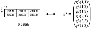
- FIG. 13A is a diagram showing the third image and the image data g3 expressed in a matrix format.
- FIG. 13B is a diagram showing an image Im41 and image data f41 expressed in a matrix format.
- FIG. 13C is a diagram showing an image Im42 and image data f42 expressed in a matrix format.
- FIG. 13D is a diagram showing an image Im43 and image data f43 expressed in a matrix format.
- FIG. 13E is a diagram showing an image Im44 and image data f44 expressed in a matrix format.
- FIG. 14A is a diagram showing the fifth image and the image data g5 expressed in a matrix format.
- FIG. 14B is a diagram showing image Im61 and image data f61 expressed in a matrix format.
- FIG. 14C is a diagram showing an image Im62 and image data f62 expressed in a matrix format.
- FIG. 14D is a diagram showing an image Im63 and image data f63 expressed in a matrix format.
- FIG. 14E is a diagram showing the image Im64 and the image data f64 expressed in a matrix format.
- all or part of a circuit, unit, device, member or section, or all or part of a functional block in a block diagram is, for example, a semiconductor device, a semiconductor integrated circuit (IC), or an LSI (large scale integration). ) may be performed by one or more electronic circuits.
- An LSI or IC may be integrated on one chip, or may be configured by combining a plurality of chips.
- functional blocks other than memory elements may be integrated into one chip.
- LSIs or ICs may be called system LSIs, VLSIs (very large scale integration), or ULSIs (ultra large scale integration) depending on the degree of integration.
- a Field Programmable Gate Array (FPGA), which is programmed after the LSI is manufactured, or a reconfigurable logic device that can reconfigure the connection relationships inside the LSI or set up the circuit partitions inside the LSI can also be used for the same purpose.
- FPGA Field Programmable Gate Array
- circuits, units, devices, members or parts can be executed by software processing.
- the software is recorded on one or more non-transitory storage media, such as ROMs, optical discs, hard disk drives, etc., such that when the software is executed by a processor, the functions specified in the software are performed. It is executed by processors and peripherals.
- a system or apparatus may include one or more non-transitory storage media on which software is recorded, a processor, and required hardware devices such as interfaces.
- a hyperspectral image is image data that has more wavelength information than a typical RGB image.
- An RGB image has values for each of three bands, red (R), green (G), and blue (B), for each pixel.
- a hyperspectral image has values for more bands per pixel than the number of bands in an RGB image.
- "hyperspectral image” means image data that includes a plurality of images corresponding to each of four or more bands contained in a predetermined wavelength range of interest.
- a value that each pixel has for each band is referred to as a "pixel value" in the following description.
- the number of bands in a hyperspectral image is typically 10 or more, and may exceed 100 in some cases.
- a "hyperspectral image” is sometimes referred to as a “hyperspectral datacube” or “hyperspectral cube.”
- FIG. 1A is a diagram for explaining the relationship between a target wavelength band W and a plurality of bands W 1 , W 2 , . . . , W i included therein.
- the target wavelength band W can be set in various ranges depending on the application.
- the target wavelength range W can be, for example, a visible light wavelength range from about 400 nm to about 700 nm, a near-infrared wavelength range from about 700 nm to about 2500 nm, or a near-ultraviolet wavelength range from about 10 nm to about 400 nm.
- the target wavelength range W may be a mid-infrared or far-infrared wavelength range.
- the wavelength range used is not limited to the visible light range. In this specification, not only visible light but also electromagnetic waves with wavelengths outside the visible light wavelength range, such as ultraviolet rays and near-infrared rays, are referred to as "light" for convenience.
- i is an arbitrary integer equal to or greater than 4, and the respective wavelength ranges obtained by equally dividing the target wavelength range W into i are defined as bands W 1 , W 2 , . . . , W i .
- a plurality of bands included in the target wavelength band W may be set arbitrarily.
- the bands may have uneven widths. There may be gaps between adjacent bands. If the number of bands is four or more, more information can be obtained from the hyperspectral image than from the RGB image.
- FIG. 1B is a diagram schematically showing an example of the hyperspectral image 22.
- the imaging target is an apple.
- Hyperspectral image 22 includes image 22W 1 for band W 1 , image 22W 2 for band W 2 , . . . , image 22W i for band W i .
- Each of these images includes a plurality of pixels arranged two-dimensionally.
- FIG. 1B exemplifies vertical and horizontal dashed lines indicating divisions of pixels.
- the actual number of pixels per image can be a large value, such as tens of thousands to tens of millions, but in FIG.
- each photodetector element in the image sensor It is Reflected light generated when an object is irradiated with light is detected by each photodetector element in the image sensor.
- a signal indicating the amount of light detected by each photodetector represents the pixel value of the pixel corresponding to that photodetector.
- Each pixel in the hyperspectral image 22 has a pixel value for each band. Therefore, by acquiring the hyperspectral image 22, it is possible to obtain information on the two-dimensional distribution of the spectrum of the object. Based on the spectrum of the object, the optical properties of the object can be accurately analyzed.
- the hyperspectral image data includes a plurality of pixel values of a plurality of pixels included in the image 22W1 , a plurality of pixel values of a plurality of pixels included in the image 22W2 , . It may be a plurality of pixel values, or information indicating the reflectance of the subject obtained by standardizing the plurality of pixel values.
- a hyperspectral image can be acquired by imaging using a spectroscopic element such as a prism or grating, for example.
- a spectroscopic element such as a prism or grating
- the light is emitted from the emission surface of the prism at an emission angle corresponding to the wavelength.
- a grating when reflected light or transmitted light from an object enters the grating, the light is diffracted at a diffraction angle according to the wavelength.
- a hyperspectral image can be obtained by splitting the light from the object into bands using a prism or grating and detecting the separated light for each band.
- a hyperspectral image can also be obtained using the compressed sensing technique disclosed in Patent Document 1.
- an image sensor detects light reflected from an object through a filter array called an encoding element or an encoding mask.
- the filter array includes a plurality of filters arranged two-dimensionally. Each of these filters has a unique transmission spectrum. Imaging using such a filter array yields a compressed image in which image information of a plurality of bands is compressed as one two-dimensional image.
- the spectral information of the object is compressed and recorded as one pixel value for each pixel.
- each pixel contained in the compressed image contains information corresponding to multiple bands.
- FIG. 2A is a diagram schematically showing an example of the filter array 10.
- the filter array 10 includes a plurality of filters arranged two-dimensionally. Each filter has an individually set transmission spectrum.
- the transmission spectrum is represented by a function T( ⁇ ), where ⁇ is the wavelength of incident light.
- the transmission spectrum T( ⁇ ) can take a value of 0 or more and 1 or less.
- the filter array 10 has 48 rectangular filters arranged in 6 rows and 8 columns. This is only an example and in actual applications more filters may be provided.
- the number of filters included in the filter array 10 may be approximately the same as the number of pixels of the image sensor.
- 2B and 2C are diagrams showing examples of transmission spectra of the first filter A1 and the second filter A2, respectively, among the plurality of filters included in the filter array 10 of FIG. 2A.
- the transmission spectrum of the first filter A1 and the transmission spectrum of the second filter A2 are different from each other.
- the transmission spectrum of the filter array 10 differs depending on the filters. However, it is not necessary that all filters have different transmission spectra.
- the filter array 10 includes multiple types of filters with different transmission spectra.
- the number of transmission spectrum patterns of the plurality of types of filters included in the filter array 10 can be equal to or greater than the number i of bands included in the target wavelength band.
- Filter array 10 may be designed such that more than half of the filters have different transmission spectra.
- FIG. 2D is a diagram showing an example of the spatial distribution of the light transmittance of each of a plurality of bands W 1 , W 2 , . . . , W i included in the target wavelength range.
- the difference in shade of each filter represents the difference in light transmittance.
- a lighter filter has a higher transmittance, and a darker filter has a lower transmittance.
- the spatial distribution of light transmittance differs depending on the band.
- the data representing the spatial distribution of light transmittance for each band in the filter array is referred to as a "restoration table".
- Compressed sensing techniques can reconstruct hyperspectral images from compressed images using reconstruction tables.
- compressed sensing techniques do not require the use of prisms or gratings, hyperspectral cameras can be made smaller. Furthermore, compressed sensing techniques can reduce the amount of data processed by the processing circuitry by compressing multiple spectral information into a single compressed image. Details of how to obtain hyperspectral images by compressed sensing techniques are disclosed in US Pat. The entire disclosure of Patent Document 1 is incorporated herein by reference.
- a restoration table corresponding to the filter array 10 is defined as a matrix by calibration before imaging.
- the accuracy of the reconstruction table has a great influence on the accuracy of the actual reconstructed image. Therefore, it is required to calibrate the restoration table accurately. For this reason, hyperspectral cameras are shipped after generating an accurate reconstruction table through careful calibration at the time of manufacture.
- a reconstruction table can be obtained, for example, in a tightly temperature-controlled optical chamber using a tunable laser source and an integrating sphere as follows.
- the wavelength tunable laser light source emits light with a wavelength corresponding to any one band included in the target wavelength range. By inputting the light emitted from the wavelength tunable laser light source into the integrating sphere and diffusing and reflecting the light, planarly uniform light is generated.
- the planarly uniform light is detected by the image sensor through the filter array 10 .
- a reconstruction table is generated by performing the above operations for all bands included in the target wavelength band. If the wavelength range of interest includes 10 bands, 10 photodetections are performed in the calibration of the reconstruction table.
- the restoration accuracy of the hyperspectral image will deteriorate. decreases.
- the deviation of the restoration table is defined by how much each element of the matrix constituting the restoration table acquired at the time of manufacture differs from the actual light transmittance of the filter array 10 . If there is a deviation in the reconstruction table, the user typically sends the hyperspectral camera back to the manufacturer. The manufacturer performs the above calibration again and creates a new restoration table. It is time consuming and costly to send the hyperspectral camera back to the manufacturer each time the reconstruction table drifts.
- the hyperspectral camera can be used stably in the long term.
- an imaging system that allows the user to easily calibrate the reconstruction table on site.
- Patent Document 2 discloses a method of calibrating a spectroscopic device at a work site. In this calibration, the wavelength deviation of the spectral profile obtained by the spectroscopic device is corrected.
- the system used for calibration includes an integrating sphere, a white plate, and a grating in addition to the xenon lamp and sensor array.
- the integrating sphere diffusely reflects and homogenizes the light emitted from the xenon lamp.
- a white plate is attached to the aperture of the integrating sphere and reflects the light homogenized within the integrating sphere.
- the grating separates the light reflected by the white plate into bands and makes the light incident on each pixel of the sensor array.
- a spectral profile is obtained from the intensity of light incident on each pixel of the sensor array for each band.
- the deviation of the wavelength of the spectral profile obtained by the spectroscopic device is corrected.
- the system does not correct for deviations in the reconstruction table used in compressed sensing techniques.
- the system is still bulky with the integrating sphere and grating.
- An imaging system includes an imaging device that employs compression sensing technology and a light source that emits reference light used for calibration to correct a reconstruction table.
- the imaging system according to this embodiment does not require a grating for band spectroscopy and an integrating sphere that diffusely reflects and homogenizes light, so it is compact and inexpensive.
- the imaging system according to this embodiment does not require strict temperature control.
- the user can easily perform calibration for correcting the restoration table under the actual usage environment. Imaging systems and methods performed by imaging systems according to embodiments of the present disclosure are described below.
- An imaging system is an imaging system using compression sensing technology, which generates image data based on a filter array including a plurality of types of filters having different transmission spectra, and light passing through the filter array.
- a processing circuit that generates hyperspectral image data including: Prepare. The processing circuit corrects the reconstruction table based on reference image data generated by the image sensor detecting the reference light.
- This imaging system facilitates the calibration of imaging devices that use compressed sensing technology.
- the imaging system according to the second item is the imaging system according to the first item, further comprising a storage device for storing spectral data of the reference light.
- the processing circuit generates reference restored image data based on the restoration table and the reference image data, and corrects the restoration table based on the spectral data stored in the storage device and the reference restored image data. do.
- the restoration table can be easily corrected based on the spectral data of the reference light and the reference restoration image data.
- the imaging system according to the third item is the imaging system according to the second item, wherein the processing circuit stores the corrected restoration table in the storage device.
- An imaging system is the imaging system according to any one of the first to third items, wherein the processing circuit converts information about the usage status of the imaging system before correction to the corrected restoration table. and stored in the storage device.
- the post-correction restoration table associated with the above information can be used as a use case.
- the imaging system according to the fifth item is the imaging system according to any one of the first to fourth items, wherein the reference light has wavelengths in at least two bands among the four or more bands.
- the imaging system according to the sixth item is the imaging system according to any one of the first to fifth items, wherein the reference light has all wavelengths of the four or more bands.
- the imaging system according to the seventh item is the imaging system according to the fifth or sixth item, wherein the reference image data includes data of a plurality of pixels. Data for each of the plurality of pixels includes information corresponding to wavelengths of two or more bands of the reference light.
- the reference image data is compressed image data.
- An imaging system is the imaging system according to any one of the first to seventh items, wherein the number of the bands included in the target wavelength range in the calibration is less than the number of the bands included in the image sensor.
- the reference image data is generated by detecting the reference light a number of times.
- the reference image data can be efficiently generated by detecting the reference light a smaller number of times than the number of bands included in the target wavelength range.
- the imaging system according to the ninth item is the imaging system according to any one of the first to eighth items, wherein the light source is a surface light source having a light exit surface.
- the image sensor generates the reference image data by imaging the light exit surface through the filter array.
- the photodetection surface of the image sensor can be uniformly illuminated with reference light.
- An imaging system is the imaging system according to any one of the first to ninth items, wherein the processing circuit causes a display device to display a GUI for a user to instruct the start of the calibration. .
- calibration can be started according to user instructions via the GUI.
- the imaging system according to the eleventh item is the imaging system according to the tenth item, wherein the processing circuit causes a display device to display a GUI for inputting information about the usage status of the imaging system before the calibration. .
- correction data with the same or similar usage conditions can be read from past correction data.
- the imaging system according to the twelfth item is the imaging system according to any one of the first to eleventh items, wherein the reference image data is emitted from the light source toward a reference object and reflected by the reference object. It is generated by the image sensor detecting the reference light.
- reference light can be detected through a reference object to generate reference image data.
- the imaging system according to the thirteenth item is the imaging system according to any one of the first to twelfth items, wherein the correction of the restoration table causes the deviation of the element corresponding to the transmission spectrum included in the restoration table. including correcting
- An imaging system is an imaging system using compressed sensing technology, wherein image data is generated by a filter array including a plurality of types of filters having mutually different transmission spectra, and imaging through the filter array.
- a storage device for storing spectral data for the reference object. The processing circuit corrects the reconstruction table based on reference image data generated by imaging the reference object whose spectral data is stored in the storage device.
- the restoration table can be corrected based on the reference data generated by detecting the light generated by the ambient light reflected by the reference object.
- the method according to the fifteenth item is a computer-implemented method of processing data related to the technique of compressed sensing.
- an image sensor that generates image data based on light passing through a filter array including a plurality of types of filters with different transmission spectra is at least one of four or more bands included in the target wavelength range.
- obtaining reference image data generated by detecting reference light having a band of wavelengths obtaining a reconstruction table determined based on the spatial distribution of the transmission spectra of the plurality of types of filters; and calibrating the reconstruction table based on reference image data.
- This method facilitates the calibration of imaging devices that use compressed sensing techniques.
- the method according to the sixteenth item is the method according to the fifteenth item, comprising obtaining spectral data of the reference light and generating reference restored image data based on the restoration table and the reference image data. and correcting the reconstruction table based on the spectral data and the reference reconstructed image data.
- the restoration table can be easily corrected based on the spectral data of the reference light and the reference restored image data.
- the method according to the seventeenth item, in the method according to the sixteenth item, further includes storing the corrected restoration table in a storage device.
- the hyperspectral image data of the object can be generated more accurately based on the stored corrected restoration table.
- FIG. 3 is a block diagram that schematically illustrates the configuration of an imaging system according to an exemplary embodiment of the present disclosure
- An imaging system 200 shown in FIG. 3 includes an imaging device 100 and a light source 70 .
- the imaging device 100 includes a filter array 10 , an image sensor 20 , an optical system 30 , a storage device 40 , a display device 50 , a processing circuit 60 and a memory 62 .
- the imaging device 100 functions as a hyperspectral camera.
- the imaging device 100 shown in FIG. 3 may be part of the configuration of, for example, a mobile terminal or a personal computer.
- the filter array 10 has a light incident surface 10s.
- the filter array 10 modulates the intensity of the light incident on the light incident surface 10s for each filter and emits the light. Details of the filter array 10 are as described above.
- the image sensor 20 has a photodetection surface 20s and includes a plurality of photodetection elements arranged two-dimensionally along the photodetection surface 20s.
- the width of the light detection surface 20s of the image sensor 20 is approximately equal to the width of the light incident surface 10s of the filter array 10.
- FIG. The image sensor 20 is arranged at a position that receives light that has passed through the filter array 10 .
- a plurality of photodetecting elements included in the image sensor 20 correspond to a plurality of filters included in the filter array 10, respectively.
- Image sensor 20 generates image data based on light passing through filter array 10 .
- the image sensor 20 can be, for example, a CCD (Charge-Coupled Device) sensor, a CMOS (Complementary Metal Oxide Semiconductor) sensor, or an infrared array sensor.
- Photodetector elements may include, for example, photodiodes.
- the image sensor 20 can be, for example, a monochrome type sensor or a color type sensor.
- the optical system 30 is located between the filter array 10 and the light source 70. Filter array 10 and light source 70 are positioned on the optical axis of optical system 30 .
- Optical system 30 includes at least one lens. In the example shown in FIG. 3, the optical system 30 is composed of one lens, but may be composed of a combination of a plurality of lenses. The optical system 30 forms an image on the photodetection surface 20 s of the image sensor 20 via the filter array 10 .
- the storage device 40 stores a restoration table corresponding to the transmission characteristics of the filter array 10. If the user has never calibrated, the restoration table is the table created by the manufacturer.
- the storage device 40 may further store past correction data for the restoration table, as will be described later.
- the storage device 40 may further store spectral data of the reference light emitted from the light source 70, as will be described later.
- the display device 50 displays a GUI (Graphic User Interface) for the user to instruct to start imaging an object and a GUI for the user to instruct to start calibration.
- GUI Graphic User Interface
- the display device 50 may be, for example, the display of a mobile terminal or personal computer.
- the processing circuit 60 controls the operations of the image sensor 20, the storage device 40, and the display device 50. Processing circuitry 60 generates hyperspectral image data based on the reconstruction table and the image data generated by image sensor 20 . In addition, processing circuitry 60 performs the necessary processing for calibration to correct the reconstruction table. A computer program executed by the processing circuitry 60 is stored in a memory 62 such as ROM or RAM (Random Access Memory). Thus, imaging device 100 includes a processing unit including processing circuitry 60 and memory 62 . The processing circuitry 60 and memory 62 may be integrated on one circuit board or provided on separate circuit boards. The functionality of processing circuitry 60 may be distributed over multiple circuitry.
- the light source 70 is used for calibration for correcting the restoration table.
- the light source 70 emits reference light having a wavelength of at least one of four or more bands included in the target wavelength region W.
- FIG. The at least one band may be, for example, a band in which the reconstruction table is considered to be out of alignment.
- a dashed line with an arrow shown in FIG. 3 represents the optical path of the reference light that passes through the optical system 30 and enters the light incident surface 10 s of the filter array 10 . Filter array 10 and optical system 30 are positioned on the optical path of the reference light.
- the light source 70 may be, for example, a surface light source having a light exit surface 70s.
- the reference light is uniformly emitted from the entire light emission surface 70s.
- the width of the light exit surface 70s of the light source 70, the lens diameter of the optical system 30, and the width of the light entrance surface 10s of the filter array 10 are appropriately designed so that the reference light emitted from the light exit surface 70s of the light source 70 The light passes through the optical system 30 and enters the entire light incident surface 10 s of the filter array 10 . With such a configuration, the entire light incident surface 10s of the filter array 10 can be uniformly illuminated with the reference light.
- FIGS. 4A and 4B are diagrams schematically showing examples of spectra of reference light emitted from the light source 70 in this embodiment.
- the vertical axis shown in FIGS. 4A and 4B represents the intensity of the reference light, and the horizontal axis represents the wavelength.
- the target wavelength range W is from 400 nm to 600 nm.
- the wavelength range of interest W is divided into ten bands W1 to W10 at intervals of 20 nm. In the example shown in FIG.
- the reference beams have wavelengths in bands W4, W5 , and W7.
- the reference light is effective when there is a deviation of the restoration table in bands W 4 , W 5 and W 7 .
- the reference light has wavelengths for all bands W1 to W10. This reference light is effective when there is a deviation of the restoration table in all bands W1 to W10 .
- the light source 70 may emit reference light having wavelengths of all bands W1 to W10 . If it is known in advance that there is a deviation in the restoration table for only one band, the light source 70 may emit only the light of the wavelength of that band as the reference light.
- the light source 70 includes light of the wavelength of the one band and does not include light of the wavelength of the other band. Light may be emitted as reference light.
- the hyperspectral image data of the reference light when there is no deviation in the restoration table can have, for example, the same pixel values in the image data for each band.
- the image data for each of bands W 4 , W 5 and W 7 are all identical and have pixel values greater than zero. Image data for other bands have pixel values near zero.
- Spectral data of the reference light emitted from the light source 70 can be obtained, for example, by any of the following methods (1) to (3).
- the data obtained by any of the methods (1)-(3) may be provided as a data set from the manufacturer of the light source 70.
- the methods (1) and (2) may be performed by the user himself/herself.
- the spectral data of the reference light may be stored in the storage device 40 before calibration for correcting the restoration table.
- the user may input the spectral data of the reference light using the input device before or during the calibration that corrects the reconstruction table.
- the processing circuit 60 acquires spectral data of the input reference light from the input device.
- the image data g and the hyperspectral image data f are vector data
- the restoration table A is matrix data.
- the image data g is represented as a one-dimensional array or vector having Ng elements.
- the hyperspectral image includes multiple images
- the hyperspectral image data f includes multiple pixel values of multiple pixels included in each of the multiple images.
- the hyperspectral image data f is represented as a one-dimensional array or vector having N f ⁇ M elements.
- the reconstruction table A is represented as a matrix with N g rows (N f ⁇ M) columns of elements.
- N g and N f can be designed to the same value.
- the number of bands M is equal to the number of images included in the hyperspectral image.
- the processing circuit 60 utilizes the redundancy of the images contained in the data f to find the solution using the technique of compressed sensing. Specifically, the desired data f is estimated by solving the following equation (2).
- Equation (2) means finding f that minimizes the sum of the first and second terms.
- the processing circuit 60 can converge the solution by recursive iteration and calculate the final solution f.
- the first term in parentheses in formula (2) means an operation for obtaining the sum of squares of differences between acquired data g and Af obtained by system-transforming f in the estimation process using matrix A.
- the second term, ⁇ (f), is a constraint on the regularization of f, and is a function that reflects the sparse information of the estimated data. As a function, it has the effect of smoothing or stabilizing the estimated data.
- the regularization term may be represented by, for example, the Discrete Cosine Transform (DCT), Wavelet Transform, Fourier Transform, or Total Variation (TV) of f. For example, when the total variation is used, it is possible to acquire stable estimated data that suppresses the influence of noise in the observed data g.
- DCT Discrete Cosine Transform
- TV Total Variation
- the sparsity of an object in the space of each regularization term depends on the texture of the object.
- a regularization term may be chosen that makes the texture of the object more spars in the space of regularization terms.
- multiple regularization terms may be included in the operation.
- ⁇ is a weighting factor. The larger the weighting factor ⁇ , the larger the reduction amount of redundant data and the higher the compression ratio. The smaller the weighting factor ⁇ , the weaker the convergence to the solution.
- the weighting factor ⁇ is set to an appropriate value with which f converges to some extent and does not become over-compressed.
- the actual restoration table is represented by A s represented by A.
- the deviation of the reconstruction table is the deviation of the element corresponding to the transmission spectrum contained in the reconstruction table.
- the imaging device 100 has a light guiding wall that separates an optical path i of light i that is emitted from a filter i and is incident on a pixel i and an optical path j of light j that is emitted from a filter j and is incident on a pixel j. (1 ⁇ j ⁇ N f , i ⁇ j). That is, the plurality of filters included in the filter array 10 and the plurality of pixels included in the image sensor 20 may be in one-to-one correspondence. In this case matrix A is a diagonal matrix.
- the shift component As can be calculated.
- the restoration table before correction can be corrected to the actual restoration table A s A.
- FIG. 5 is a flow chart showing an example of operations performed by the processing circuitry 60 when imaging an object.
- the "HS image” shown in the following figures represents the hyperspectral image.
- the user sends a signal to the processing circuit 60 to start imaging the object via the GUI displayed on the display device 50 .
- the processing circuit 60 receives the signal and executes the operations of steps S101 to S103 below.
- Step S101> The processing circuit 60 issues an imaging command to the image sensor 20 .
- Image sensor 20 in response to this command, images the object through filter array 10 and produces compressed image data thereof.
- Step S102> The processing circuit 60 acquires the compressed image data of the object from the image sensor 20 and acquires the restoration table from the storage device 40 .
- Processing circuitry 60 restores the hyperspectral image data of the object based on equations (1) and (2) based on the compressed image data and the restoration table obtained in step S102. Processing circuitry 60 may store the reconstructed hyperspectral image data in storage device 40 .
- the reconstructed hyperspectral image data can be used for various purposes, such as inspection of foreign substances contained in objects such as industrial products or foods, or analysis of the components of objects. If the accuracy of analysis or inspection is low for some or all of the bands included in the target wavelength region W, the user considers what the cause is. As a result of examination, if it is found that there is a deviation between the restoration table and the characteristics of the optical element such as the filter array 10, the user performs calibration to correct the deviation of the restoration table as follows. .
- the storage device 40 stores past correction data for the restoration table, the user uses that correction data. For example, when an error occurs in the restoration result due to replacement of a lens included in the optical system 30, the cause is considered to be a change in lens characteristics. Therefore, if the same type of lens was used in the past, the restoration table can be corrected using past correction data. Lenses of the same type have, for example, the same lens focal length and F-number. By associating the past correction data with the use case, the user can use the past correction data based on the use case.
- Use case information is, for example, case A: "lens focal length: 100 mm, F value: 2.4, installed on factory belt conveyor No.
- the use case information may include information about the usage of the imaging system, such as the focal length and f-number of the lens, and the location of the lens.
- the user places the light source 70 in front of the imaging device 100 as shown in FIG. 3 and performs calibration for correcting the restoration table.
- FIG. 6 is a flow chart showing an example of operations performed by the processing circuitry 60 during calibration.
- the user After causing the light source 70 to emit the reference light, the user performs an operation to start calibration via the GUI displayed on the display device 50 .
- a signal is sent to processing circuitry 60 to initiate calibration.
- the processing circuit 60 receives the signal and executes the operations of steps S201 to S206 below.
- the processing circuit 60 may execute the operations of steps S201 to S206 below.
- the processing circuitry 60 causes the image sensor 20 to detect the reference light through the filter array 10 and generate its compressed image data.
- this data is called "reference image data”.
- the image sensor 20 images the light exit surface 70s through the filter array 10 to generate reference image data.
- the reference light may contain light of wavelengths in all bands included in the target wavelength range, or may contain only light of wavelengths in some bands of the target wavelength range.
- the reference light includes only light of wavelengths in some bands of the target wavelength range
- the reference light includes light of wavelengths in some bands of the target wavelength range and other wavelengths of the target wavelength range.” It does not include the light of the wavelengths of the bands.
- the wavelength range of interest consists of some bands and other bands.”
- the reference light of the wavelengths of different bands may be divided into multiple times and detected for the multiple bands in which the restoration table is shifted. For example, if there is a deviation in the restoration table in three bands included in the target wavelength range, the reference light of the wavelengths of two bands is first detected among the three bands, and then the reference light of the remaining one band is detected. A wavelength reference beam may be detected.
- the number of times of detection is two.
- the reference light emitted for each band may be individually detected.
- the number of times of detection is three.
- the image sensor 20 can generate reference image data by detecting the reference light a number of times less than the number of all bands included in the target wavelength range W.
- the image sensor 20 can generate reference image data by detecting the reference light a number of times less than the number of bands in the reconstruction table to be corrected.
- Step S202> The processing circuit 60 acquires the reference image data from the image sensor 20 and acquires the reconstruction table from the storage device 40 .
- the processing circuitry 60 restores the hyperspectral image data of the reference light from the data acquired in step S202.
- the data has a pixel value greater than zero in the image data for at least one band included in the reference light, and has a pixel value substantially zero in the image data for the other bands.
- image data for at least one band included in the reference light is referred to as "reference restored image data”.
- the processing circuitry 60 may cause the storage device 40 to store the reference restored image data.
- steps S201 to S203 are the same as the operations from steps S101 to S103 shown in FIG.
- Processing circuitry 60 acquires spectral data of the reference light. If the storage device 40 stores reference beam spectral data, the processing circuit 60 retrieves the reference beam spectral data from the storage device 40 . Alternatively, when the user inputs the spectral data of the reference light using an external input device, the processing circuit 60 acquires the spectral data of the reference light from the input device.
- Step S205> The processing circuit 60 corrects the deviation of the restoration table based on the restored reference image data generated in step S203 and the spectral data of the reference light acquired in step S204.
- the specific calculation for the correction is as described above.
- Processing circuitry 60 updates the restoration table stored in storage device 40 to the restoration table corrected in step S205.
- the processing circuit 60 causes the storage device 40 to newly store the corrected restoration table in place of the uncorrected restoration table.
- the corrected restoration table may be separately stored in the storage device 40 while the restoration table before correction remains in the storage device 40 .
- the restoration table is corrected as described above.
- the user executes steps S101 to S103 shown in FIG. 5 to regenerate the hyperspectral image data of the object.
- Hyperspectral image data can be generated more accurately if the reconstruction table shifts are correctly corrected. Therefore, it can be expected that the regenerated hyperspectral image data will improve the accuracy of the analysis. If the accuracy of the analysis does not improve, the user may return the imaging device 100 to the manufacturer, as the reconstruction table may not have been properly corrected for deviation.
- the imaging system 200 according to the present embodiment there is no need to split the reference light into bands, nor to homogenize the reference light by diffusely reflecting it. Therefore, the imaging system 200 according to this embodiment does not need to be provided with a spectroscopic element or an integrating sphere, and is compact and inexpensive. Furthermore, the imaging system according to this embodiment does not require strict temperature control. With the imaging system according to this embodiment, the user can easily perform calibration for correcting the restoration table under the actual use environment.
- FIGS. 7A to 7C are diagrams schematically showing examples of data stored in the storage device 40.
- FIG. 7A represents an example of a restoration table.
- FIG. 7B represents an example of spectral data of reference light emitted from the light source 70.
- FIG. 7C represents an example of past correction data for the restoration table. When there are multiple use cases, multiple past correction data corresponding to the multiple use cases can be stored in the storage device 40 .
- the restoration table shown in FIG. 7A includes information on the light transmittance of a plurality of filters arranged two-dimensionally in each band.
- Filter numbers such as filter 1 and filter 2 shown in FIG. 7A are identification numbers of a plurality of filters included in the filter array 10 .
- Numerical values from 0 to 1 shown in FIG. 7A represent the light transmittance of each filter.
- the spectral data of the reference light shown in FIG. 7B includes spectral intensity information for each band.
- the light source 70 is a surface light source
- the past correction data for the reconstruction table shown in FIG. 7C represents the correction ratio of the light transmittance of the multiple filters in each band.
- each correction ratio shown in FIG. 7C is multiplied by the corresponding light transmittance in the restoration table shown in FIG. 7A.
- FIG. 8A is a diagram schematically showing a first example of a GUI displayed on the display device 50.
- the user selects either the hyperspectral image capture button located on the upper left side of the GUI shown in FIG. 8A or the calibration button located on the upper right side, depending on the purpose.
- FIG. 8A shows an example of the GUI when the button for calibration is selected.
- the GUI shown in FIG. 8A includes a load button for reading spectral data of reference light and a start button for starting calibration. The user selects the load button to load the spectral data of the reference light. The user then selects the start button to initiate calibration.
- the GUI shown in FIG. 8A further includes a save button for saving the correction data after calibration and a load button for reading the saved correction data. After calibration, the user selects the save button to save the correction data after linking it with the use case.
- correction data suitable for calibration may be read from the past correction data as follows.
- the user inputs information on the usage status of the imaging system to be calibrated, for example, into the GUI, and selects the load button to read the past correction data.
- the load button By this operation, it is possible to read, from among past correction data, correction data whose use situation is the same as or similar to that of the imaging system to be calibrated from now on.
- the user selects the start button to initiate calibration. As described above, calibration is performed based on the read correction data.
- FIG. 8B is a diagram schematically showing a second example of the GUI displayed on the display device 50.
- the GUI shown in FIG. 8B includes pull-down lists for imaging targets, calibration wavelengths, and lenses used.
- the “lighting”, “white board” and “color chart” included in the imaging target list will be described later.
- the user selects from among the use cases included in the list a use case that has the same or similar usage conditions as the imaging system to be calibrated.
- the user selects the start button to initiate calibration. As described above, calibration is performed based on the selected use case.
- FIG. 9A is a perspective view schematically showing an example of the external shape of the imaging system 200 according to this embodiment.
- FIG. 9B is a perspective view when the light source 70 shown in FIG. 9A is viewed from the light exit surface 70s side.
- the light source 70 is attached as an attachment to the optical system 30 of the imaging device 100 in the direction of the arrow. Since the light source 70 does not need to have a spectroscopic element, it can be a small attachment.
- light source 70 has the shape of a bottomed cylinder.
- the inner bottom surface is the light exit surface 70s.
- optical system 30 fits within the cylindrical portion of light source 70 .
- the reference light emitted from the light emission surface 70 s of the light source 70 can be efficiently incident on the optical system 30 .
- FIG. 9A since the light source 70 is simply attached to the optical system 30, there is no need to move the imaging device 100 from the site for calibration.
- FIG. 10A is a diagram schematically showing an example of an imaging system according to Modification 1 of the embodiment of the present disclosure.
- An imaging system 210 shown in FIG. 10A includes an imaging device 100, a light source 72, and a white board 74 as a reference object.
- a region surrounded by dashed lines shown in FIG. 10A schematically represents the range of light emitted from the light source 72 toward the white plate 74 .
- Light emitted from the light source 72 and reflected by the white plate 74 enters the optical system 30 as reference light.
- the reflectance spectrum of the white plate 74 can be, for example, substantially flat in the wavelength range of interest, or can vary slowly.
- the processing circuitry 60 causes the image sensor 20 to detect the reference light through the filter array 10 and generate reference image data.
- the spectral data of the reference light used for correcting the restoration table may be stored in the storage device 40 before calibration for correcting the restoration table.
- the user may input the spectral data of the reference light using the input device before or during the calibration that corrects the reconstruction table.
- the spectral data of the reference light stored in the storage device 40 or input by the user may be, for example, spectral data of light obtained under the same conditions as the calibration described above.
- the information regarding the type and/or model number of the light source 72 and the type of the white plate 74 may be associated with the spectral data of the reference light.
- FIG. 10B is a diagram schematically showing an example of an imaging system according to modification 2 of the embodiment of the present disclosure.
- An imaging system 220 shown in FIG. 10B includes an imaging device 100 and a color chart 76 as a reference object.
- the color chart 76 includes a plurality of color samples arranged two-dimensionally. Light generated by reflection of ambient light such as sunlight or illumination light on the color chart 76 enters the optical system 30 as reference light.
- the processing circuitry 60 causes the image sensor 20 to detect the reference light through the filter array 10 and generate reference image data.
- the spectral data of the reference light used for correcting the restoration table may be stored in the storage device 40 before calibration for correcting the restoration table.
- the user may input the spectral data of the color chart 76 using an input device before or during the calibration that corrects the reconstruction table.
- the spectral data of the reference light stored in the storage device 40 or input by the user may be, for example, spectral data of light obtained under the same conditions as the calibration described above.
- the type and/or model number of the color chart 76 and the spectral data of the reference light may be linked and stored.
- An imaging system may be as follows.
- the imaging system includes an imaging device,
- the imaging device includes a filter including a plurality of regions, an image sensor, a memory for storing a first matrix, and circuitry,
- the plurality of regions exhibit a plurality of transmittance characteristics in a wavelength range,
- the plurality of transmittance characteristics and the plurality of regions have a one-to-one correspondence, the plurality of transmittance characteristics are different from each other,
- the plurality of wavelength bands include a first wavelength band, to n-th wavelength bands, and n is There are natural numbers greater than or equal to 4, (a) in a first period, which is a period before calibration of the imaging device, (a-1)
- the filter receives first light including light from a first subject and outputs second light, and the image sensor responds to the second light incident on the image sensor.
- the filter receives fifth light including light from a second object and outputs sixth light, and the image sensor responds to the sixth light incident on the image sensor.
- the circuit generates a plurality of sixth image data based on the first matrix, the second matrix, and the fifth image data;
- Image data corresponds one to one
- g5 indicates a column vector in which a plurality of pixel values included in the fifth image data are a plurality of components
- f61, ⁇ , f6n are a plurality of column vectors indicating the plurality of sixth image data
- the first light includes light in the first wavelength band, to light in the n-th wavelength band
- the fifth light includes light in the first wavelength band, to light in the nth wavelength band
- the third light includes light in the i-th wavelength band; the third light does not include the light in the first wavelength band, to the light in the (i-1)th wavelength band, the third light does not include light in the (i+1)-th wavelength band, to light in the n-th wavelength band
- the period before the imaging device 100 is calibrated is the first period
- the period during the calibration of the imaging device 100 is the second period
- the period after the imaging device 100 is calibrated is the third period.
- the target wavelength band W includes multiple wavelength bands.
- the plurality of wavelength bands are a first wavelength band, . . . , an n-th wavelength band.
- the i-th wavelength band and the j-th wavelength band do not contain the same wavelength (1 ⁇ i ⁇ j ⁇ n).
- Filter array 10 includes a plurality of regions.
- the plurality of regions exhibit a plurality of transmittance characteristics in the target wavelength region W.
- the multiple transmittance characteristics are different from each other.
- a plurality of regions and a plurality of transmittance characteristics correspond one-to-one.
- a plurality of wavelength bands included in the target wavelength band W are wavelength band W 1 , wavelength band W 2 , wavelength band W 3 , and wavelength band W 4 .
- Image sensor 20 outputs a compressed image.
- the filter array 10 receives first light including light from a first object and outputs second light.
- the first light includes light in the first wavelength band, to light in the fourth wavelength band.
- the image sensor 20 receives the second light and outputs the first image including the first image data g1 to the processing circuit 50.
- FIG. 11A shows the first image and the image data g1 expressed in a matrix format.
- the first image includes a pixel located at the coordinates (1,1) indicating the pixel value g1(1,1), and a pixel located at the coordinates (2,3) indicating the pixel value g1(2,3).
- Image data g1 corresponding to the first image includes pixel values g1(1,1), . . . , pixel values g1(2,3).
- the processing circuit 50 generates a plurality of second image data corresponding to a plurality of wavelength bands included in the target wavelength region W based on the first image data g1 and the first matrix A1 stored in the storage device 40.
- the plurality of wavelength bands are wavelength band W1, wavelength band W2 , wavelength band W3, and wavelength band W4, and the plurality of second image data are image data f21, image data f22, image data f23, and image data f24 .
- the first image is an image in which an image Im21 corresponding to the wavelength band W1, an image Im22 corresponding to the wavelength band W2 , an image Im23 corresponding to the wavelength band W3, and an image Im24 corresponding to the wavelength band W4 are superimposed. You can think of it (see eg FIG. 1B).
- Image data f21 corresponds to image Im21
- image data f22 corresponds to image Im22
- image data f23 corresponds to image Im23
- image data f24 corresponds to image Im24.
- the plurality of filters included in the filter array 10 and the plurality of pixels included in the image sensor 20 may correspond one-to-one.
- A1 is a diagonal matrix.
- FIG. 11B shows the image Im21 and the image data f21 expressed in a matrix format.
- Image Im21 includes a pixel positioned at coordinates (1,1) indicating pixel value f21(1,1), a pixel positioned at coordinates (2,3) indicating pixel value f21(2,3).
- Image data f21 corresponding to image Im21 includes pixel values f21(1,1), . . . , pixel values f21(2,3).
- FIG. 11C shows the image Im22 and the image data f22 expressed in a matrix format.
- the image Im22 includes a pixel positioned at coordinates (1,1) indicating a pixel value f22(1,1) to a pixel positioned at coordinates (2,3) indicating a pixel value f22(2,3).
- Image data f22 corresponding to image Im22 includes pixel values f22(1,1), . . . , pixel values f22(2,3).
- FIG. 11D shows the image Im23 and the image data f23 expressed in a matrix format.
- Image Im23 includes a pixel positioned at coordinates (1,1) indicating pixel value f23(1,1), a pixel positioned at coordinates (2,3) indicating pixel value f23(2,3).
- Image data f23 corresponding to image Im23 includes pixel values f23(1,1), . . . , pixel values f23(2,3).
- FIG. 11E shows the image Im24 and the image data f24 expressed in matrix form.
- Image Im24 includes a pixel positioned at coordinates (1,1) indicating pixel value f24(1,1), a pixel positioned at coordinates (2,3) indicating pixel value f24(2,3).
- Image data f24 corresponding to image Im24 includes pixel values f24(1,1), . . . , pixel values f24(2,3).
- the filter array 10 receives the third light emitted from the light source 70 and outputs the fourth light.
- the third light may be the reference light described in the embodiment (see FIGS. 4A, 4B, etc.).
- FIG. 12 shows spectrum data of the third light.
- the third light includes light in wavelength band W1, does not include light in wavelength band W2 , does not include light in wavelength band W3, and does not include light in wavelength band W4 .
- the image sensor 20 receives the third light and outputs to the processing circuit 50 a third image including the third image data g3.
- FIG. 13A shows the third image and the image data g3 expressed in matrix format.
- the third image includes a pixel located at coordinates (1,1) indicating a pixel value g3(1,1), a pixel located at coordinates (2,3) indicating a pixel value g3(2,3).
- Image data g3 corresponding to the third image includes pixel values g3(1,1), . . . , pixel values g3(2,3).
- the processing circuit 50 determines the second matrix As based on the first matrix A1, the third image data g3, and the fourth data I.
- the processing circuitry 50 causes the storage device 40 to store the second matrix As.
- the third image is an image in which an image Im41 corresponding to the wavelength band W1, an image Im42 corresponding to the wavelength band W2 , an image Im43 corresponding to the wavelength band W3, and an image Im44 corresponding to the wavelength band W4 are superimposed. You can think of it (see eg FIG. 1B).
- the plurality of wavelength bands are wavelength band W1, wavelength band W2 , wavelength band W3, and wavelength band W4, and the plurality of fourth image data are image data f41, image data f42, image data f43, and image data f44.
- FIG. 13B shows an image Im41 and image data f41 expressed in a matrix format.
- Image Im41 includes a pixel positioned at coordinates (1,1) indicating pixel value f41(1,1), a pixel positioned at coordinates (2,3) indicating pixel value f41(2,3).
- Image data f41 corresponding to image Im41 includes pixel values f41(1,1), . . . , pixel values f41(2,3). Since the third light exhibits spectral data as shown in FIG. 12, all pixels included in the image Im41 have the same pixel value, eg, p (p is a value of 0 or more).
- FIG. 13C shows an image Im42 and image data f42 expressed in a matrix format.
- Image Im42 includes a pixel positioned at coordinates (1,1) indicating pixel value f42(1,1), a pixel positioned at coordinates (2,3) indicating pixel value f42(2,3).
- Image data f42 corresponding to image Im42 includes pixel values f42(1,1), . . . , pixel values f42(2,3). Since the third light exhibits spectral data as shown in FIG. 12, the pixel values of all the pixels included in the image Im42 are zero.
- FIG. 13D shows the image Im43 and the image data f43 expressed in a matrix format.
- Image Im43 includes a pixel positioned at coordinates (1,1) indicating pixel value f43(1,1), a pixel positioned at coordinates (2,3) indicating pixel value f43(2,3).
- Image data f43 corresponding to image Im43 includes pixel values f43(1,1), . . . , pixel values f43(2,3). Since the third light exhibits spectral data as shown in FIG. 12, the pixel values of all the pixels included in the image Im43 are zero.
- FIG. 13E shows the image Im44 and the image data f44 expressed in a matrix format.
- Image Im44 includes a pixel positioned at coordinates (1,1) indicating pixel value f44(1,1), a pixel positioned at coordinates (2,3) indicating pixel value f44(2,3).
- Image data f44 corresponding to image Im44 includes pixel values f44(1,1), . . . , pixel values f44(2,3). Since the third light exhibits spectral data as shown in FIG. 12, the pixel values of all the pixels included in the image Im44 are zero.
- the filter array 10 receives fifth light including light from the second object and outputs sixth light.
- the fifth light includes light in the first wavelength band, to light in the fourth wavelength band.
- the second subject may be the first subject.
- the image sensor 20 receives the sixth light and outputs to the processing circuit 50 a fifth image including the fifth image data g5.
- FIG. 14A shows the fifth image and the image data g5 expressed in matrix form.
- the fifth image includes a pixel located at coordinates (1,1) indicating a pixel value g5(1,1), a pixel located at coordinates (2,3) indicating a pixel value g5(2,3).
- Image data g5 corresponding to the fifth image includes pixel values g5(1,1), . . . , pixel values g5(2,3).
- the processing circuit 50 generates a plurality of sixth image data corresponding to a plurality of wavelength bands included in the target wavelength band W based on the fifth image data g5 and the first matrix A1 and the second matrix As stored in the storage device 40. to generate
- the plurality of wavelength bands are wavelength band W1, wavelength band W2 , wavelength band W3, and wavelength band W4, and the plurality of sixth image data are image data f61 , image data f62, image data f63, and image data f64.
- the fifth image is an image in which an image Im61 corresponding to the wavelength band W1, an image Im62 corresponding to the wavelength band W2 , an image Im63 corresponding to the wavelength band W3, and an image Im64 corresponding to the wavelength band W4 are superimposed. You can think of it (see eg FIG. 1B).
- Image data f61 corresponds to image Im61
- image data f62 corresponds to image Im62
- image data f63 corresponds to image Im63
- image data f64 corresponds to image Im64.
- FIG. 14B shows an image Im61 and image data f61 expressed in a matrix format.
- the image Im61 includes a pixel positioned at coordinates (1,1) indicating a pixel value f61(1,1) to a pixel positioned at coordinates (2,3) indicating a pixel value f61(2,3).
- Image data f61 corresponding to image Im61 includes pixel values f61(1,1), . . . , pixel values f61(2,3).
- FIG. 14C shows an image Im62 and image data f62 expressed in a matrix format.
- Image Im62 includes a pixel positioned at coordinates (1,1) indicating pixel value f62(1,1), a pixel positioned at coordinates (2,3) indicating pixel value f62(2,3).
- Image data f62 corresponding to image Im62 includes pixel values f62(1,1), . . . , pixel values f62(2,3).
- FIG. 14D shows an image Im63 and image data f63 expressed in a matrix format.
- Image Im63 includes a pixel positioned at coordinates (1,1) indicating pixel value f63(1,1), a pixel positioned at coordinates (2,3) indicating pixel value f63(2,3).
- Image data f63 corresponding to image Im63 includes pixel values f63(1,1), . . . , pixel values f63(2,3).
- FIG. 14E shows the image Im64 and the image data f64 expressed in matrix format.
- Image Im64 includes a pixel positioned at coordinates (1,1) indicating pixel value f64(1,1), a pixel positioned at coordinates (2,3) indicating pixel value f64(2,3).
- Image data f64 corresponding to image Im64 includes pixel values f64(1,1), . . . , pixel values f64(2,3).
- the imaging system according to the present disclosure can be applied to calibration of imaging devices that use compression sensing technology.
- REFERENCE SIGNS LIST 10 filter array 10s light incident surface 20 image sensor 20s light detection surface 30 optical system 40 storage device 50 display device 60 processing device 62 memory 70 light source 70s light exit surface 100 imaging device 200 imaging system
Landscapes
- Physics & Mathematics (AREA)
- Spectroscopy & Molecular Physics (AREA)
- Engineering & Computer Science (AREA)
- General Physics & Mathematics (AREA)
- Multimedia (AREA)
- Signal Processing (AREA)
- Computer Vision & Pattern Recognition (AREA)
- Theoretical Computer Science (AREA)
- Spectrometry And Color Measurement (AREA)
Abstract
撮像システム(200)は、圧縮センシングの技術を用いる撮像システムであって、透過スペクトルが互いに異なる複数種類のフィルタを含むフィルタアレイ(10)と、前記フィルタアレイ(10)を通過する光に基づく画像データを生成するイメージセンサ(20)と、前記複数種類のフィルタの前記透過スペクトルの空間分布に基づいて決定される復元テーブル、および前記画像データに基づいて、対象波長域に含まれる4つ以上のバンドに対応する画像を含むハイパースペクトル画像データを生成する処理回路(60)と、前記復元テーブルを補正するキャリブレーションに用いられる、前記4つ以上のバンドのうちの少なくとも1つのバンドの波長を有する参照光を出射する光源(70)と、を備え、前記処理回路(60)は前記イメージセンサ(20)が前記参照光を検出することによって生成した参照画像データに基づいて前記復元テーブルを補正する。
Description
本開示は、撮像システム、および撮像システムによって実行される方法に関する。
ハイパースペクトルカメラは、一般的なRBGカメラと比較して、対象物についてより多くの波長情報を得ることができる。ハイパースペクトルカメラによって撮像された対象物のハイパースペクトル画像に基づいて、対象物のスペクトル特性を正確に分析することができる。ハイパースペクトルカメラは、分析、研究、および製品の検査などの様々な用途に用いられることが期待されている。ハイパースペクトルカメラには、プリズムまたはグレーティングなどの分光素子を用いる方式と、特許文献1に開示されている圧縮センシングの技術が用いる方式とがある。
ハイパースペクトルカメラが例えば経年劣化すると、ハイパースペクトル画像から得られる波長情報の精度が低下する可能性がある。この場合、ハイパースペクトルカメラのキャリブレーションが行われる。特許文献2は、分光素子を用いる分光装置のキャリブレーションの例を開示している。
本開示は、圧縮センシングの技術を用いる撮像装置のキャリブレーションを容易にする撮像システムを提供する。
本開示の一態様に係る撮像システムは、圧縮センシングの技術を用いる撮像システムであって、透過スペクトルが互いに異なる複数種類のフィルタを含むフィルタアレイと、前記フィルタアレイを通過する光に基づく画像データを生成するイメージセンサと、前記複数種類のフィルタの前記透過スペクトルの空間分布に基づいて決定される復元テーブル、および前記画像データに基づいて、対象波長域に含まれる4つ以上のバンドに対応する画像を含むハイパースペクトル画像データを生成する処理回路と、前記復元テーブルを補正するキャリブレーションに用いられる、前記4つ以上のバンドのうちの少なくとも1つのバンドの波長を有する参照光を出射する光源と、を備え、前記処理回路は、前記イメージセンサが前記参照光を検出することによって生成した参照画像データに基づいて、前記復元テーブルを補正する。
本開示の包括的または具体的な態様は、システム、装置、方法、集積回路、コンピュータプログラムまたはコンピュータ読み取り可能な記録媒体で実現されてもよく、システム、装置、方法、集積回路、コンピュータプログラムおよび記録媒体の任意の組み合わせで実現されてもよい。コンピュータ読み取り可能な記録媒体は、例えばCD-ROM(Compact Disc‐Read Only Memory)等の不揮発性の記録媒体を含む。装置は、1つ以上の装置で構成されてもよい。装置が2つ以上の装置で構成される場合、当該2つ以上の装置は、1つの機器内に配置されてもよく、分離した2つ以上の機器内に分かれて配置されてもよい。本明細書および特許請求の範囲では、「装置」とは、1つの装置を意味し得るだけでなく、複数の装置からなるシステムも意味し得る。「システム」に含まれる複数の装置の中には、他の装置とは遠隔地に設置され、通信ネットワーク介して接続される装置も含み得る。
本開示の技術によれば、圧縮センシングの技術を用いる撮像装置のキャリブレーションを容易にする撮像システムを実現することができる。
本開示において、回路、ユニット、装置、部材または部の全部または一部、またはブロック図における機能ブロックの全部または一部は、例えば、半導体装置、半導体集積回路(IC)、またはLSI(large scale integration)を含む1つまたは複数の電子回路によって実行され得る。LSIまたはICは、1つのチップに集積されてもよいし、複数のチップを組み合わせて構成されてもよい。例えば、記憶素子以外の機能ブロックは、1つのチップに集積されてもよい。ここでは、LSIまたはICと呼んでいるが、集積の度合いによって呼び方が変わり、システムLSI、VLSI(very large scale integration)、もしくはULSI(ultra large scale integration)と呼ばれるものであってもよい。LSIの製造後にプログラムされる、Field Programmable Gate Array(FPGA)、またはLSI内部の接合関係の再構成またはLSI内部の回路区画のセットアップができるreconfigurable logic deviceも同じ目的で使うことができる。
さらに、回路、ユニット、装置、部材または部の全部または一部の機能または操作は、ソフトウェア処理によって実行することが可能である。この場合、ソフトウェアは1つまたは複数のROM、光学ディスク、ハードディスクドライブなどの非一時的記録媒体に記録され、ソフトウェアが処理装置(processor)によって実行されたときに、そのソフトウェアで特定された機能が処理装置(processor)および周辺装置によって実行される。システムまたは装置は、ソフトウェアが記録されている1つまたは複数の非一時的記録媒体、処理装置(processor)、および必要とされるハードウェアデバイス、例えばインターフェースを備えていてもよい。
以下、本開示の例示的な実施形態を説明する。なお、以下で説明する実施形態は、いずれも包括的又は具体的な例を示すものである。以下の実施形態で示される数値、形状、構成要素、構成要素の配置位置及び接続形態、ステップ、ステップの順序などは、一例であり、本開示を限定する主旨ではない。また、以下の実施形態における構成要素のうち、最上位概念を示す独立請求項に記載されていない構成要素については、任意の構成要素として説明される。また、各図は模式図であり、必ずしも厳密に図示されたものではない。さらに、各図において、実質的に同一の構成要素に対しては同一の符号を付しており、重複する説明は省略又は簡略化される場合がある。
本開示の実施形態を説明する前に、本開示の基礎となった知見を説明する。
まず、図1Aおよび図1Bを参照して、ハイパースペクトル画像の例を簡単に説明する。ハイパースペクトル画像は、一般的なRGB画像よりも多くの波長の情報を有する画像データである。RGB画像は、画素ごとに、赤(R)、緑(G)、および青(B)の3つのバンドのそれぞれについての値を有する。これに対し、ハイパースペクトル画像は、RGB画像のバンド数よりも多くのバンドについての値を画素ごとに有する。本明細書において、「ハイパースペクトル画像」は、予め定められた対象波長域に含まれる4つ以上のバンドのそれぞれに対応する複数の画像を含む画像データを意味する。各画素がバンドごとに有する値を、以下の説明において、「画素値」と称する。ハイパースペクトル画像におけるバンド数は、典型的には10以上であり、場合によっては100を超えることもある。「ハイパースペクトル画像」は、「ハイパースペクトルデータキューブ」または「ハイパースペクトルキューブ」と呼ばれることもある。
図1Aは、対象波長域Wと、それに含まれる複数のバンドW1、W2、・・・、Wiとの関係を説明するための図である。対象波長域Wは、用途によって様々な範囲に設定され得る。対象波長域Wは、例えば、約400nmから約700nmの可視光の波長域、約700nmから約2500nmの近赤外線の波長域、または約10nmから約400nmの近紫外線の波長域であり得る。あるいは、対象波長域Wは、中赤外または遠赤外の波長域であってもよい。このように、使用される波長域は可視光域とは限らない。本明細書では、可視光に限らず、紫外線および近赤外線などの可視光の波長域に含まれない波長の電磁波も便宜上「光」と称する。
図1Aに示す例では、iを4以上の任意の整数として、対象波長域Wをi等分したそれぞれの波長域をバンドW1、W2、・・・、Wiとしている。ただしこのような例に限定されない。対象波長域Wに含まれる複数のバンドは任意に設定してもよい。例えば、バンドによって幅を不均一にしてもよい。隣接するバンドの間にギャップがあってもよい。バンドの数が4つ以上であれば、RGB画像よりも多くの情報をハイパースペクトル画像から得ることができる。
図1Bは、ハイパースペクトル画像22の例を模式的に示す図である。図1Bに示す例において、撮像対象はりんごである。ハイパースペクトル画像22は、バンドW1についての画像22W1、バンドW2についての画像22W2、・・・、バンドWiについての画像22Wiを含む。これらの画像の各々は、2次元的に配列された複数の画素を含む。図1Bには、画素の区切りを示す縦横の破線が例示されている。1画像当たりの実際の画素数は、例えば数万から数千万のように大きい値であり得るが、図1Bにおいては、わかり易さのため、画素数が極端に少ないものとして画素の区切りが示されている。対象物を光で照射した場合に生じる反射光は、イメージセンサにおける光検出素子ごとに検出される。各光検出素子によって検出される光量を示す信号が、その光検出素子に対応する画素の画素値を表す。ハイパースペクトル画像22における各画素は、バンドごとに画素値を有する。したがって、ハイパースペクトル画像22を取得することにより、対象物のスペクトルの2次元分布の情報を得ることができる。対象物のスペクトルに基づいて、対象物の光に関する特性を正確に分析することができる。
ハイパースペクトル画像データは、画像22W1に含まれる複数の画素の複数の画素値、画像22W2に含まれる複数の画素の複数の画素値、・・・、画像22Wiに含まれる複数の画素の複数の画素値であってもよいし、当該複数の画素値を規格化した被写体の反射率を示す情報であってもよい。
次に、ハイパースペクトル画像を生成する方法の例を簡単に説明する。ハイパースペクトル画像は、例えばプリズムまたはグレーティングなどの分光素子を用いた撮像によって取得することができる。プリズムを用いる場合、対象物からの反射光または透過光がプリズムを通過すると、当該光はプリズムの出射面から波長に応じた出射角で出射される。グレーティングを用いる場合、対象物からの反射光または透過光がグレーティングに入射すると、当該光は波長に応じた回折角で回折される。対象物からの光をプリズムまたはグレーティングによってバンドごとに分光し、分離された光をバンドごとに検出することにより、ハイパースペクトル画像を得ることができる。
ハイパースペクトル画像は、特許文献1に開示された圧縮センシングの技術を利用して取得することもできる。特許文献1に開示された圧縮センシングの技術では、符号化素子または符号化マスクと呼ばれるフィルタアレイを通して、対象物で反射された光がイメージセンサによって検出される。フィルタアレイは、2次元的に配列された複数のフィルタを含む。それらのフィルタは、それぞれに固有の透過スペクトルを有する。そのようなフィルタアレイを用いた撮像により、複数のバンドの画像情報が1つの2次元画像として圧縮された圧縮画像が得られる。当該圧縮画像には、対象物のスペクトル情報が画素ごとに1つの画素値として圧縮されて記録される。換言すると、圧縮画像に含まれる各々の画素が、複数のバンドに対応する情報を含む。
図2Aは、フィルタアレイ10の例を模式的に示す図である。フィルタアレイ10は、2次元的に配列された複数のフィルタを含む。各フィルタは、個別に設定された透過スペクトルを有する。透過スペクトルは、入射光の波長をλとして、関数T(λ)で表される。透過スペクトルT(λ)は、0以上1以下の値を取り得る。図2Aに示す例において、フィルタアレイ10は、6行8列に配列された48個の矩形状のフィルタを有している。これはあくまで例示であり、実際の用途では、これよりも多くのフィルタが設けられ得る。フィルタアレイ10に含まれるフィルタの個数は、イメージセンサの画素数と同程度であってもよい。
図2Bおよび図2Cは、それぞれ、図2Aのフィルタアレイ10に含まれる複数のフィルタのうち、第1フィルタA1および第2フィルタA2の透過スペクトルの例を示す図である。第1フィルタA1の透過スペクトルと第2フィルタA2の透過スペクトルとは、互いに異なっている。このように、フィルタアレイ10の透過スペクトルは、フィルタによって異なる。ただし、必ずしもすべてのフィルタの透過スペクトルが異なっている必要はない。フィルタアレイ10において、複数のフィルタのうちの少なくとも2つ以上のフィルタの透過スペクトルが互いに異なる。すなわち、フィルタアレイ10は、透過スペクトルが互いに異なる複数種類のフィルタを含む。ある例では、フィルタアレイ10に含まれる複数種類のフィルタの透過スペクトルのパターンの数は、対象波長域に含まれるバンドの数iと同じか、それ以上であり得る。フィルタアレイ10は、半数以上のフィルタの透過スペクトルが異なるように設計されていてもよい。
図2Dは、対象波長域に含まれる複数のバンドW1、W2、・・・、Wiのそれぞれの光の透過率の空間分布の例を示す図である。図2Dに示す例において、各フィルタの濃淡の違いは、光透過率の違いを表している。淡いフィルタほど透過率が高く、濃いフィルタほど透過率が低い。図2Dに示すように、バンドによって光透過率の空間分布が異なっている。本明細書では、フィルタアレイにおけるバンドごとの光透過率の空間分布を示すデータを「復元テーブル」と称する。圧縮センシングの技術により、復元テーブルを用いて圧縮画像からハイパースペクトル画像を復元することができる。圧縮センシングの技術ではプリズムまたはグレーティングを用いる必要がないので、ハイパースペクトルカメラを小型化することができる。さらに、圧縮センシングの技術では、複数のスペクトルの情報が1つの圧縮画像として圧縮されることにより、処理回路が処理するデータ量を低減することができる。圧縮センシングの技術によってハイパースペクトル画像を得る方法の詳細は、特許文献1に開示されている。特許文献1の開示内容の全体を本明細書に援用する。
フィルタアレイ10に対応する復元テーブルは、撮影前にキャリブレーションによって行列として定義される。復元テーブルの正確度は、実際の復元画像の精度に大きな影響を与える。したがって、復元テーブルのキャリブレーションを正確に行うことが求められる。このため、ハイパースペクトルカメラは、製造時に綿密なキャリブレーションを行うことによって正確な復元テーブルを生成した後に出荷される。復元テーブルは、例えば、厳格に温度管理された光学室において、波長可変レーザー光源および積分球を用いて以下のようにして取得され得る。波長可変レーザー光源は、対象波長域に含まれる任意の1つのバンドに対応する波長の光を出射する。波長可変レーザー光源から出射された光を積分球に入力して拡散反射させることにより、面状に均一な光が生成される。面状に均一な光は、フィルタアレイ10を介してイメージセンサによって検出される。以上の動作を対象波長域に含まれるすべてのバンドについてそれぞれ行うことにより、復元テーブルが生成される。対象波長域が10バンドを含む場合、復元テーブルのキャリブレーションにおいて10回の光検出が行われる。
製造時に高い正確度の復元テーブルを生成したとしても、出荷後に例えば経年劣化またはレンズ交換によって復元テーブルとフィルタアレイなどの光学素子の透過特性との間にずれが生じると、ハイパースペクトル画像の復元精度が低下してしまう。復元テーブルのずれは、製造時に取得された復元テーブルを構成する行列の各要素が、実際のフィルタアレイ10の光透過率からどれだけ異なっているかによって定義される。復元テーブルにずれが生じた場合、通常、ユーザはハイパースペクトルカメラを製造元に送り返す。製造元では、上記のキャリブレーションが再度行われ、復元テーブルが新たに作成される。復元テーブルにずれが生じるたびにハイパースペクトルカメラを製造元に送り返すのは、時間およびコストの点で問題がある。製造元に送り返すことなく、あらゆる撮影現場においてユーザが復元テーブルを補正することができれば、ハイパースペクトルカメラを長期的に安定して使用することができる。以上のことから、ユーザが現場において復元テーブルのキャリブレーションを簡易に行うことができる撮像システムが求められている。
特許文献2は、作業現場において分光装置のキャリブレーションを行う方法を開示している。このキャリブレーションでは、分光装置によって得られる分光プロファイルの波長のずれが補正される。特許文献2の方法において、キャリブレーションに用いられるシステムは、キセノンランプおよびセンサアレイに加えて、積分球、白色板、およびグレーティングを備える。積分球は、キセノンランプから発せられた光を拡散反射させて均一にする。白色板は積分球の開口に取り付けられ、積分球内で均一化された光を反射する。グレーティングは、白色板で反射された光をバンドごとに分光してセンサアレイの各画素に入射させる。センサアレイの各画素に入射したバンドごとの光の強度から分光プロファイルが得られる。このようにして得られた分光プロファイルと予め記憶された基準の分光プロファイルとを比較することにより、分光装置によって得られる分光プロファイルの波長のずれが補正される。当該システムは、圧縮センシングの技術に用いられる復元テーブルのずれを補正するものではない。当該システムは、積分球およびグレーティングを備えるので依然として大型である。
本発明者らは、上記の検討により、復元テーブルのキャリブレーションを簡易に行うことができる本開示の実施形態による撮像システムに想到した。本開示のある実施形態による撮像システムは、圧縮センシングの技術を用いる撮像装置と、復元テーブルを補正するためのキャリブレーションに使用される参照光を出射する光源とを備える。本実施形態による撮像システムは、バンド分光のためのグレーティング、および光を拡散反射させて均一化する積分球を備える必要ないので小型かつ安価である。さらに、本実施形態による撮像システムには、厳格な温度管理が必要ない。以上のことから、本実施形態による撮像システムにより、ユーザは、実際の使用環境下で、復元テーブルを補正するキャリブレーションを簡易に行うことができる。以下に、本開示の実施形態による撮像システム、および撮像システムによって実行される方法を説明する。
第1の項目に係る撮像システムは、圧縮センシングの技術を用いる撮像システムであって、透過スペクトルが互いに異なる複数種類のフィルタを含むフィルタアレイと、前記フィルタアレイを通過する光に基づく画像データを生成するイメージセンサと、前記複数種類のフィルタの前記透過スペクトルの空間分布に基づいて決定される復元テーブル、および前記画像データに基づいて、対象波長域に含まれる4つ以上のバンドに対応する画像を含むハイパースペクトル画像データを生成する処理回路と、前記復元テーブルを補正するキャリブレーションに用いられる、前記4つ以上のバンドのうちの少なくとも1つのバンドの波長を有する参照光を出射する光源と、を備える。前記処理回路は、前記イメージセンサが前記参照光を検出することによって生成した参照画像データに基づいて、前記復元テーブルを補正する。
この撮像システムでは、圧縮センシングの技術を用いる撮像装置のキャリブレーションが容易になる。
第2の項目に係る撮像システムは、第1の項目に係る撮像システムにおいて、前記参照光のスペクトルデータを記憶する記憶装置をさらに備える。前記処理回路は、前記復元テーブルおよび前記参照画像データに基づいて、参照復元画像データを生成し、前記記憶装置に記憶された前記スペクトルデータと前記参照復元画像データとに基づいて前記復元テーブルを補正する。
この撮像システムでは、参照光のスペクトルデータおよび参照復元画像データに基づいて、復元テーブルを簡易に補正することができる。
第3の項目に係る撮像システムは、第2の項目に係る撮像システムにおいて、前記処理回路が、補正された前記復元テーブルを前記記憶装置に記憶させる。
この撮像システムでは、記憶された補正後の復元テーブルに基づいて、対象物のハイパースペクトル画像データをより正確に生成することができる。
第4の項目に係る撮像システムは、第1から第3の項目のいずれかに係る撮像システムにおいて、前記処理回路が、補正前における前記撮像システムの使用状況に関する情報を、補正された前記復元テーブルと対応付けて前記記憶装置に記憶させる。
この撮像システムでは、上記の情報が対応付けられた補正後の復元テーブルをユースケースとして使用することができる。
第5の項目に係る撮像システムは、第1から第4の項目のいずれかに係る撮像システムにおいて、前記参照光が、前記4つ以上のバンドのうちの少なくとも2つのバンドの波長を有する。
この撮像システムでは、対象波長域に含まれる少なくとも2つのバンドについての復元テーブルのずれを補正することができる。
第6の項目に係る撮像システムは、第1から第5の項目のいずれかに係る撮像システムにおいて、前記参照光が、前記4つ以上のバンドのすべての波長を有する。
この撮像システムでは、対象波長域に含まれるすべてのバンドについての復元テーブルのずれを補正することができる。
第7の項目に係る撮像システムは、第5または第6の項目に係る撮像システムにおいて、前記参照画像データが複数の画素のデータを含む。前記複数の画素の各々のデータは、前記参照光が有する2つ以上のバンドの波長に対応する情報を含む。
この撮像システムでは、参照画像データは圧縮画像データである。
第8の項目に係る撮像システムは、第1から第7の項目のいずれかに係る撮像システムにおいて、前記イメージセンサが、前記キャリブレーションにおいて、前記対象波長域に含まれる前記バンドの数よりも少ない回数で前記参照光を検出することにより、前記参照画像データを生成する。
この撮像システムでは、対象波長域に含まれるバンドの数よりも少ない回数で参照光を検出することにより、参照画像データを効率的に生成することができる。
第9の項目に係る撮像システムは、第1から第8の項目のいずれかに係る撮像システムにおいて、前記光源が光出射面を有する面光源であり。前記イメージセンサは、前記フィルタアレイを介して前記光出射面を撮像することにより、前記参照画像データを生成する。
この撮像システムでは、イメージセンサの光検出面を参照光で均一に照射することができる。
第10の項目に係る撮像システムは、第1から第9の項目のいずれかに係る撮像システムにおいて、前記処理回路が、前記キャリブレーションの開始をユーザが指示するためのGUIを表示装置に表示させる。
この撮像システムでは、GUIを介したユーザの指示によってキャリブレーションを開始することができる。
第11の項目に係る撮像システムは、第10の項目に係る撮像システムにおいて、前記処理回路が、前記キャリブレーション前における前記撮像システムの使用状況に関する情報を入力するためのGUIを表示装置に表示させる。
この撮像システムでは、上記の情報を入力することにより、過去の補正データの中から、使用状況が同一または類似の補正データを読み込むことができる。
第12の項目に係る撮像システムは、第1から第11の項目のいずれかに係る撮像システムにおいて、前記参照画像データが、前記光源から参照物体に向けて出射され、前記参照物体で反射された前記参照光を前記イメージセンサが検出することによって生成される。
この撮像システムでは、参照物体を介した参照光を検出して参照画像データを生成することができる。
第13の項目に係る撮像システムは、第1から第12の項目のいずれかに係る撮像システムにおいて、前記復元テーブルの前記補正が、前記復元テーブルに含まれる、前記透過スペクトルに対応する要素のずれを補正することを含む。
この撮像システムでは、復元テーブルに含まれる、透過スペクトルに対応する要素のずれを補正することができる。
第14の項目に係る撮像システムは、圧縮センシングの技術を用いる撮像システムであって、透過スペクトルが互いに異なる複数種類のフィルタを含むフィルタアレイと、前記フィルタアレイを介した撮像により、画像データを生成するイメージセンサと、前記複数種類のフィルタの前記透過スペクトルの空間分布に基づいて決定される復元テーブル、および前記画像データに基づいて、対象波長域に含まれる4つ以上のバンドに対応する画像を含むハイパースペクトル画像データを生成する処理回路と、参照物体についてのスペクトルデータを記憶する記憶装置と、を備える。前記処理回路は、前記記憶装置に前記スペクトルデータが記憶されている前記参照物体を撮像することにより生成された参照画像データに基づいて、前記復元テーブルを補正する。
この撮像システムでは、環境光が参照物体で反射されて生じた光を検出して生成された参照データに基づいて、復元テーブルを補正することができる。
第15の項目に係る方法は、コンピュータによって実行される、圧縮センシングの技術に関連するデータを処理する方法である。前記方法は、透過スペクトルが互いに異なる複数種類のフィルタを含むフィルタアレイを通過する光に基づいて画像データを生成するイメージセンサが、対象波長域に含まれる4つ以上のバンドのうち、少なくとも1つのバンドの波長を有する参照光を検出することによって生成した参照画像データを取得することと、前記複数種類のフィルタの前記透過スペクトルの空間分布に基づいて決定される復元テーブルを取得することと、前記参照画像データに基づいて前記復元テーブルを補正することと、を含む。
この方法では、圧縮センシングの技術を用いる撮像装置のキャリブレーションが容易になる。
第16の項目に係る方法は、第15の項目に係る方法において、前記参照光のスペクトルデータを取得することと、前記復元テーブルおよび前記参照画像データに基づいて、参照復元画像データを生成することと、前記スペクトルデータと前記参照復元画像データとに基づいて前記復元テーブルを補正することと、をさらに含む。
この方法では、参照光のスペクトルデータおよび参照復元画像データに基づいて、復元テーブルを簡易に補正することができる。
第17の項目に係る方法は、第16の項目に係る方法において、補正された前記復元テーブルを記憶装置に記憶させることをさらに含む。
この方法では、記憶された補正後の復元テーブルに基づいて、対象物のハイパースペクトル画像データをより正確に生成することができる。
(実施形態)
[撮像システムの構成]
まず、図3を参照して、本開示の例示的な実施形態による撮像システムの構成を説明する。本実施形態による撮像システムは、圧縮センシングの技術を用いて対象物を撮像する撮像装置のキャリブレーションに用いられる。キャリブレーションでは、撮像装置に含まれるフィルタアレイに対応する復元テーブルが補正される。図3は、本開示の例示的な実施形態による撮像システムの構成を模式的に示すブロック図である。図3に示す撮像システム200は、撮像装置100と、光源70とを備える。撮像装置100は、フィルタアレイ10と、イメージセンサ20と、光学系30と、記憶装置40と、表示装置50と、処理回路60と、メモリ62とを備える。撮像装置100は、ハイパースペクトルカメラとして機能する。図3に示す撮像装置100は、例えば、モバイル端末またはパーソナルコンピュータの構成の一部であってもよい。
フィルタアレイ10は光入射面10sを有する。フィルタアレイ10は、光入射面10sに入射した光の強度をフィルタごとに変調して出射する。フィルタアレイ10の詳細については前述した通りである。
イメージセンサ20は光検出面20sを有し、光検出面20sに沿って2次元的に配列された複数の光検出素子を含む。イメージセンサ20が有する光検出面20sの広さは、フィルタアレイ10の光入射面10sの広さにほぼ等しい。イメージセンサ20は、フィルタアレイ10を通過した光を受ける位置に配置される。イメージセンサ20に含まれる複数の光検出素子は、フィルタアレイ10に含まれる複数のフィルタにそれぞれ対応する。イメージセンサ20は、フィルタアレイ10を通過する光に基づく画像データを生成する。イメージセンサ20は、例えばCCD(Charge-Coupled Device)センサ、CMOS(Complementary Metal Oxide Semiconductor)センサ、または赤外線アレイセンサであり得る。光検出素子は、例えばフォトダイオードを含み得る。イメージセンサ20は、例えばモノクロタイプのセンサ、またはカラータイプのセンサであり得る。
光学系30は、フィルタアレイ10と光源70との間に位置する。光学系30の光軸上に、フィルタアレイ10および光源70が位置する。光学系30は、少なくとも1つのレンズを含む。図3に示す例において、光学系30は1つのレンズによって構成されているが、複数のレンズの組み合わせによって構成されていてもよい。光学系30は、フィルタアレイ10を介して、イメージセンサ20の光検出面20s上に像を形成する。
記憶装置40は、フィルタアレイ10の透過特性に応じた復元テーブルを記憶する。ユーザがキャリブレーションを一度も行っていない場合、当該復元テーブルは製造元で作成されたテーブルである。記憶装置40は、後述するように、復元テーブルについての過去の補正データをさらに記憶していてもよい。記憶装置40は、後述するように、光源70から出射される参照光のスペクトルデータをさらに記憶していてもよい。
表示装置50は、対象物の撮像を開始することをユーザが指示するためのGUI(Graphic User Interface)、およびキャリブレーションを開始することをユーザが指示するためのGUIを表示する。表示装置50は、例えばモバイル端末またはパーソナルコンピュータのディスプレイであってもよい。
処理回路60は、イメージセンサ20、記憶装置40、および表示装置50の動作を制御する。処理回路60は、復元テーブルと、イメージセンサ20によって生成された画像データとに基づいて、ハイパースペクトル画像データを生成する。さらに、処理回路60は、復元テーブルを補正するキャリブレーションのための必要な処理を行う。処理回路60によって実行されるコンピュータプログラムは、ROMまたはRAM(Random Access Memory)などのメモリ62に格納されている。このように、撮像装置100は、処理回路60およびメモリ62を含む処理装置を備えている。処理回路60およびメモリ62は、1つの回路基板に集積されていてもよいし、別々の回路基板に設けられていてもよい。処理回路60の機能が複数の回路に分散していてもよい。
光源70は、復元テーブルを補正するためのキャリブレーションに用いられる。光源70は、対象波長域Wに含まれる4つ以上のバンドのうち、少なくとも1つのバンドの波長を有する参照光を出射する。当該少なくとも1つのバンドは、例えば、復元テーブルにずれが生じていると考えられるバンドであり得る。図3に示す矢印付きの破線は、光学系30を通過してフィルタアレイ10の光入射面10sに入射する参照光の光路を表す。フィルタアレイ10および光学系30は、参照光の光路上に位置する。光源70は、例えば、光出射面70sを有する面光源であり得る。光出射面70sの全体から参照光が均一に出射される。光源70の光出射面70sの広さ、光学系30のレンズ径、およびフィルタアレイ10の光入射面10sの広さは適切に設計されており、光源70の光出射面70sから出射された参照光は光学系30を通過し、フィルタアレイ10が有する光入射面10sの全体に入射する。そのような構成により、フィルタアレイ10の光入射面10sの全体を参照光で均一に照射することができる。
[参照光のスペクトルデータ]
次に、図4Aおよび図4Bを参照して、本実施形態における光源70から出射される参照光のスペクトルの例を説明する。図4Aおよび図4Bは、本実施形態における光源70から出射される参照光のスペクトルの例を模式的に示す図である。図4Aおよび図4Bに示す縦軸は参照光の強度を表し、横軸は波長を表す。図4Aおよび図4Bに示す例において、対象波長域Wは400nm以上600nm以下である。対象波長域Wは、20nm間隔で10個のバンドW1からW10に分割されている。図4Aに示す例において、参照光は、バンドW4、W5、およびW7の波長を有する。当該参照光は、バンドW4、W5、およびW7において復元テーブルのずれが生じている場合に有効である。図4Bに示す例において、参照光は、全バンドW1からW10の波長を有する。当該参照光は、全バンドW1からW10において復元テーブルのずれが生じている場合に有効である。どのバンドで復元テーブルのずれが生じているかが予めわからない場合、光源70は、全バンドW1からW10の波長を有する参照光を出射してもよい。1つのバンドについてのみ復元テーブルのずれが生じていることが予めわかっている場合、光源70は、そのバンドの波長の光のみを参照光として出射してもよい。1つのバンドについて復元テーブルのずれが生じ、他のバンドについて復元テーブルのずれが生じていない場合、光源70は当該1つのバンドの波長の光を含み、当該他のバンドの波長の光を含まない光を参照光として出射してもよい。
次に、図4Aおよび図4Bを参照して、本実施形態における光源70から出射される参照光のスペクトルの例を説明する。図4Aおよび図4Bは、本実施形態における光源70から出射される参照光のスペクトルの例を模式的に示す図である。図4Aおよび図4Bに示す縦軸は参照光の強度を表し、横軸は波長を表す。図4Aおよび図4Bに示す例において、対象波長域Wは400nm以上600nm以下である。対象波長域Wは、20nm間隔で10個のバンドW1からW10に分割されている。図4Aに示す例において、参照光は、バンドW4、W5、およびW7の波長を有する。当該参照光は、バンドW4、W5、およびW7において復元テーブルのずれが生じている場合に有効である。図4Bに示す例において、参照光は、全バンドW1からW10の波長を有する。当該参照光は、全バンドW1からW10において復元テーブルのずれが生じている場合に有効である。どのバンドで復元テーブルのずれが生じているかが予めわからない場合、光源70は、全バンドW1からW10の波長を有する参照光を出射してもよい。1つのバンドについてのみ復元テーブルのずれが生じていることが予めわかっている場合、光源70は、そのバンドの波長の光のみを参照光として出射してもよい。1つのバンドについて復元テーブルのずれが生じ、他のバンドについて復元テーブルのずれが生じていない場合、光源70は当該1つのバンドの波長の光を含み、当該他のバンドの波長の光を含まない光を参照光として出射してもよい。
復元テーブルにずれが生じていない場合における参照光のハイパースペクトル画像データは、例えば、各バンドについての画像データにおいてすべて同じ画素値を有し得る。図4Aに示す例において、バンドW4、W5、およびW7の各々についての画像データは、すべて同じであって、ゼロより大きい画素値を有する。それ以外のバンドについての画像データは、ほぼゼロの画素値を有する。光源70がそのような参照光を出射する場合、復元テーブルを補正するキャリブレーションの精度を向上させることができる。
光源70から出射される参照光のスペクトルデータは、例えば以下の(1)-(3)のいずれかの方法で取得され得る。
(1)分光装置を用いて参照光のスペクトルデータを取得する。
(2)復元テーブルにずれが生じていないときの撮像装置100を用いて参照光のスペクトルデータを取得する。
(3)光源70の定格スペクトルデータを用いる。
(1)分光装置を用いて参照光のスペクトルデータを取得する。
(2)復元テーブルにずれが生じていないときの撮像装置100を用いて参照光のスペクトルデータを取得する。
(3)光源70の定格スペクトルデータを用いる。
(1)-(3)のいずれかの方法によって取得されたデータは、光源70の製造元からデータセットとして提供されてもよい。あるいは、(1)および(2)の方法については、ユーザ自らが実行してもよい。
参照光のスペクトルデータは、復元テーブルを補正するキャリブレーションの前に記憶装置40に記憶されていてもよい。あるいは、復元テーブルを補正するキャリブレーションの前または最中に、ユーザが、入力装置を用いて参照光のスペクトルデータを入力してもよい。その場合、処理回路60は、入力された参照光のスペクトルデータを入力装置から取得する。
[復元テーブルのずれを補正する演算]
次に、復元テーブルのずれを補正する演算の例を説明する。イメージセンサ20によって取得された画像データg、復元テーブルA、およびハイパースペクトル画像データfは、以下の式(1)を満たす。
次に、復元テーブルのずれを補正する演算の例を説明する。イメージセンサ20によって取得された画像データg、復元テーブルA、およびハイパースペクトル画像データfは、以下の式(1)を満たす。

ここで、画像データgおよびハイパースペクトル画像データfは、ベクトルのデータであり、復元テーブルAは、行列のデータである。画像データgの画素数をNgとすると、画像データgは、Ng個の要素を持つ1次元配列すなわちベクトルとして表される。ハイパースペクトル画像は複数の画像を含み、ハイパースペクトル画像データfは当該複数の画像の各々に含まれる複数の画素の複数の画素値を含む。当該複数の画像の各々に含まれる複数の画素の数をNf、バンド数をMとすると、ハイパースペクトル画像データfは、Nf×M個の要素を持つ1次元配列すなわちベクトルとして表される。復元テーブルAは、Ng行(Nf×M)列の要素を持つ行列として表される。NgおよびNfは同じ値に設計され得る。バンド数Mはハイパースペクトル画像に含まれる複数の画像の数に等しい。
ベクトルgと行列Aが与えられれば、式(1)の逆問題を解くことにより、fを算出することができそうである。しかし、求めるデータfの要素数Nf×Mが取得データgの要素数Ngよりも多いため、この問題は不良設定問題であり、このままでは解くことができない。そこで、処理回路60は、データfに含まれる画像の冗長性を利用し、圧縮センシングの手法を用いて解を求める。具体的には、以下の式(2)を解くことにより、求めるデータfが推定される。

ここで、f’は、推定されたfのデータを表す。上式の括弧内の第1項は、推定結果Afと取得データgとのずれ量、いわゆる残差項を表す。ここでは2乗和を残差項としているが、絶対値あるいは二乗和平方根などを残差項としてもよい。括弧内の第2項は、後述する正則化項または安定化項である。式(2)は、第1項と第2項との和を最小化するfを求めることを意味する。処理回路60は、再帰的な反復演算によって解を収束させ、最終的な解fを算出することができる。
式(2)の括弧内の第1項は、取得データgと、推定過程のfを行列Aによってシステム変換したAfとの差分の二乗和を求める演算を意味する。第2項のΦ(f)は、fの正則化における制約条件であり、推定データのスパース情報を反映した関数である。働きとしては、推定データを滑らかまたは安定にする効果がある。正則化項は、例えば、fの離散的コサイン変換(DCT)、ウェーブレット変換、フーリエ変換、またはトータルバリエーション(TV)などによって表され得る。例えば、トータルバリエーションを使用した場合、観測データgのノイズの影響を抑えた安定した推測データを取得できる。それぞれの正則化項の空間における対象物のスパース性は、対象物のテキスチャによって異なる。対象物のテキスチャが正則化項の空間においてよりスパースになる正則化項を選んでもよい。あるいは、複数の正則化項を演算に含んでもよい。τは、重み係数である。重み係数τが大きいほど冗長的なデータの削減量が多くなり、圧縮する割合が高まる。重み係数τが小さいほど解への収束性が弱くなる。重み係数τは、fがある程度収束し、かつ、過圧縮にならない適度な値に設定される。
経年劣化などの種々の原因により、復元テーブルAとフィルタアレイ10などの光学素子の透過特性との間にずれが生じた場合、実際の復元テーブルは、ずれ成分を対角行列AsとしてAsAによって表される。このとき、AsA=AAsの関係が成り立つ。復元テーブルのずれは、復元テーブルに含まれる、透過スペクトルに対応する要素のずれである。参照光をイメージセンサ20によって検出する場合、ハイパースペクトル画像データfとして、参照光のスペクトルデータIが用いられる。イメージセンサ20によって取得された画像データg、実際の復元テーブルAAs、および参照光のスペクトルデータIは、以下の式(3)を満たす。フィルタアレイ10に含まれる複数のフィルタをフィルタ1、~、フィルタNf、イメージセンサ20に含まれる複数の画素を画素1、~、画素Nfとした場合、フィルタiから出力された光iは、画素iに入射し、かつ、画素1、~、画素(i-1)、画素(i+1)、~、画素Nfに入射しないように、撮像装置100が設計されていてもよい(1≦i≦Nf)。例えば、撮像装置100は、フィルタiから出射し、画素iに入射する光iの光路iと、フィルタjから出射し、画素jに入射する光jの光路jとを分離する壁を有する導光部を含んでもよい(1≦j≦Nf、i≠j)。つまり、フィルタアレイ10に含まれる複数のフィルタとイメージセンサ20に含まれる複数の画素を、1対1対応させてもよい。この場合、行列Aは対角行列である。

式(1)と式(3)との比較から、ずれが生じた復元テーブルを用いる場合、ハイパースペクトル画像データとしてf=AsIが得られる。ハイパースペクトル画像データfから2次元スペクトルデータIを除くことにより、ずれの成分Asを算出することができる。算出されたずれの成分Asを補正前の復元テーブルAに掛けることにより、補正前の復元テーブルを、実際の復元テーブルAsAに補正することができる。
[対象物の撮像]
復元テーブルを補正するキャリブレーションの例を説明する前に、図5を参照して、対象物を撮像する場合の、処理回路60の動作の例を説明する。この場合、図3に示す例において、光源70ではなく対象物が撮像装置100の前に配置される。図5は、対象物を撮像する場合の、処理回路60が実行する動作の例を示すフローチャートである。これ以降の図に示す「HS画像」はハイパースペクトル画像を表す。ユーザは、表示装置50に表示されるGUIを介して対象物の撮像を開始する信号を処理回路60に送信する。処理回路60は、当該信号を受けて以下のステップS101からS103の動作を実行する。
復元テーブルを補正するキャリブレーションの例を説明する前に、図5を参照して、対象物を撮像する場合の、処理回路60の動作の例を説明する。この場合、図3に示す例において、光源70ではなく対象物が撮像装置100の前に配置される。図5は、対象物を撮像する場合の、処理回路60が実行する動作の例を示すフローチャートである。これ以降の図に示す「HS画像」はハイパースペクトル画像を表す。ユーザは、表示装置50に表示されるGUIを介して対象物の撮像を開始する信号を処理回路60に送信する。処理回路60は、当該信号を受けて以下のステップS101からS103の動作を実行する。
<ステップS101>
処理回路60は、イメージセンサ20に撮像の指令を出す。イメージセンサ20は、この指令に応答して、フィルタアレイ10を通して対象物を撮像し、その圧縮画像データを生成する。
処理回路60は、イメージセンサ20に撮像の指令を出す。イメージセンサ20は、この指令に応答して、フィルタアレイ10を通して対象物を撮像し、その圧縮画像データを生成する。
<ステップS102>
処理回路60は、イメージセンサ20から対象物の圧縮画像データを取得し、記憶装置40から復元テーブルを取得する。
処理回路60は、イメージセンサ20から対象物の圧縮画像データを取得し、記憶装置40から復元テーブルを取得する。
<ステップS103>
処理回路60は、ステップS102において取得した圧縮画像データおよび復元テーブルに基づいて、対象物のハイパースペクトル画像データを式(1)および式(2)に基づいて復元する。処理回路60は、復元したハイパースペクトル画像データを記憶装置40に記憶させてもよい。
処理回路60は、ステップS102において取得した圧縮画像データおよび復元テーブルに基づいて、対象物のハイパースペクトル画像データを式(1)および式(2)に基づいて復元する。処理回路60は、復元したハイパースペクトル画像データを記憶装置40に記憶させてもよい。
復元されたハイパースペクトル画像データは、例えば工業製品または食品などの対象物に含まれる異物の検査、または対象物の成分の分析などの種々の目的で使用され得る。対象波長域Wに含まれるバンドの一部または全部について、分析または検査の精度が低い場合、ユーザはその原因が何であるかを検討する。検討の結果、復元テーブルとフィルタアレイ10などの光学素子の特性との間にずれが生じていることが判明すれば、ユーザは以下のようにして復元テーブルのずれを補正するキャリブレーションを実行する。
[復元テーブルのずれの補正]
記憶装置40が復元テーブルについての過去の補正データを記憶している場合、ユーザはその補正データを使用する。例えば、光学系30に含まれるレンズの交換によって復元結果に誤差が生じた場合、その原因はレンズの特性の変化であると考えられる。このため、過去に同じ種類のレンズを使っていた場合、過去の補正データを使用して復元テーブルを補正することができる。同じ種類のレンズは、例えば、レンズの焦点距離およびF値が同じである。過去の補正データとユースケースとを紐づけておけば、ユーザは、ユースケースに基づいて過去の補正データを使用することができる。ユースケースの情報は、例えば、ケースAとして「レンズの焦点距離:100mm、F値:2.4、工場のベルトコンベア1号機に設置」、ケースBとして「レンズの焦点距離:50mm、F値:1.5、工場のベルトコンベア3号機に設置」のような情報である。このように、ユースケースの情報は、レンズの焦点距離およびF値、ならびにレンズの設置場所などの、撮像システムの使用状況に関する情報を含んでいてもよい。
記憶装置40が復元テーブルについての過去の補正データを記憶している場合、ユーザはその補正データを使用する。例えば、光学系30に含まれるレンズの交換によって復元結果に誤差が生じた場合、その原因はレンズの特性の変化であると考えられる。このため、過去に同じ種類のレンズを使っていた場合、過去の補正データを使用して復元テーブルを補正することができる。同じ種類のレンズは、例えば、レンズの焦点距離およびF値が同じである。過去の補正データとユースケースとを紐づけておけば、ユーザは、ユースケースに基づいて過去の補正データを使用することができる。ユースケースの情報は、例えば、ケースAとして「レンズの焦点距離:100mm、F値:2.4、工場のベルトコンベア1号機に設置」、ケースBとして「レンズの焦点距離:50mm、F値:1.5、工場のベルトコンベア3号機に設置」のような情報である。このように、ユースケースの情報は、レンズの焦点距離およびF値、ならびにレンズの設置場所などの、撮像システムの使用状況に関する情報を含んでいてもよい。
記憶装置40が復元テーブルについての過去の補正データを記憶していない場合、ユーザは、図3に示すように光源70を撮像装置100の前に配置し、復元テーブルを補正するキャリブレーションを行う。
以下に、図6を参照して、復元テーブルを補正するキャリブレーションにおける処理回路60の動作の例を説明する。図6は、キャリブレーションにおいて、処理回路60が実行する動作の例を示すフローチャートである。ユーザは、光源70に参照光を出射させた後、表示装置50に表示されるGUIを介してキャリブレーションを開始する操作を行う。この操作に応答して、キャリブレーションを開始する信号が処理回路60に送信される。処理回路60は、当該信号を受けて以下のステップS201からS206の動作を実行する。なお、処理回路60が光源70を制御できる構成においては、ユーザが光源70に参照光を出射させる操作を行う必要はない。処理回路60は、ユーザからのキャリブレーション開始の指示に応答して、光源70に参照光を出射させた後、以下のステップS201からS206の動作を実行してもよい。
<ステップS201>
処理回路60は、イメージセンサ20にフィルタアレイ10を介して参照光を検出させてその圧縮画像データを生成させる。本明細書において、当該データを「参照画像データ」と称する。光源70が面光源である場合、イメージセンサ20は、フィルタアレイ10を介して光出射面70sを撮像して参照画像データを生成する。本実施形態による撮像システム200では、参照光が複数のバンドの波長の光を含んでいる場合でも、イメージセンサ20は参照光を1回検出すれば十分である。参照光は、対象波長域に含まれるすべてのバンドの波長の光を含んでいてもよいし、対象波長域の一部のバンドの波長の光のみを含んでいてもよい。「参照光が対象波長域の一部のバンドの波長の光のみを含む」とは、「参照光は、対象波長域の一部のバンドの波長の光を含み、当該対象波長域の他のバンドの波長の光を含まない。対象波長域は一部のバンドと他のバンドからなる。」と解釈してもよい。参照光の波長が可変である場合、復元テーブルにずれが生じている複数のバンドについて、異なるバンドの波長の参照光を複数回に分けて検出してもよい。例えば対象波長域に含まれる3つのバンドにおいて復元テーブルにずれが生じている場合、当該3つのバンドのうち、最初に2つのバンドの波長の参照光を検出し、次に残りの1つのバンドの波長の参照光を検出してもよい。この場合、検出回数は2回である。あるいは、3つのバンドのうち、バンドごとに出射された参照光を個別に検出してもよい。この場合、検出回数は3回である。このように、イメージセンサ20は、対象波長域Wに含まれる全バンドの数よりも少ない回数で参照光を検出することにより、参照画像データを生成することができる。さらに、イメージセンサ20は、補正の対象となる復元テーブルのバンドの数よりも少ない回数で参照光を検出することにより、参照画像データを生成することができる。
処理回路60は、イメージセンサ20にフィルタアレイ10を介して参照光を検出させてその圧縮画像データを生成させる。本明細書において、当該データを「参照画像データ」と称する。光源70が面光源である場合、イメージセンサ20は、フィルタアレイ10を介して光出射面70sを撮像して参照画像データを生成する。本実施形態による撮像システム200では、参照光が複数のバンドの波長の光を含んでいる場合でも、イメージセンサ20は参照光を1回検出すれば十分である。参照光は、対象波長域に含まれるすべてのバンドの波長の光を含んでいてもよいし、対象波長域の一部のバンドの波長の光のみを含んでいてもよい。「参照光が対象波長域の一部のバンドの波長の光のみを含む」とは、「参照光は、対象波長域の一部のバンドの波長の光を含み、当該対象波長域の他のバンドの波長の光を含まない。対象波長域は一部のバンドと他のバンドからなる。」と解釈してもよい。参照光の波長が可変である場合、復元テーブルにずれが生じている複数のバンドについて、異なるバンドの波長の参照光を複数回に分けて検出してもよい。例えば対象波長域に含まれる3つのバンドにおいて復元テーブルにずれが生じている場合、当該3つのバンドのうち、最初に2つのバンドの波長の参照光を検出し、次に残りの1つのバンドの波長の参照光を検出してもよい。この場合、検出回数は2回である。あるいは、3つのバンドのうち、バンドごとに出射された参照光を個別に検出してもよい。この場合、検出回数は3回である。このように、イメージセンサ20は、対象波長域Wに含まれる全バンドの数よりも少ない回数で参照光を検出することにより、参照画像データを生成することができる。さらに、イメージセンサ20は、補正の対象となる復元テーブルのバンドの数よりも少ない回数で参照光を検出することにより、参照画像データを生成することができる。
<ステップS202>
処理回路60は、イメージセンサ20から参照画像データを取得し、記憶装置40から復元テーブルを取得する。
処理回路60は、イメージセンサ20から参照画像データを取得し、記憶装置40から復元テーブルを取得する。
<ステップS203>
処理回路60は、ステップS202において取得したデータから参照光のハイパースペクトル画像データを復元する。当該データは、参照光に含まれる少なくとも1つのバンドについての画像データにおいてゼロより大きい画素値を有し、それ以外のバンドについての画像データにおいてほぼゼロの画素値を有する。本明細書において、当該データのうち、参照光に含まれる少なくとも1つのバンドについての画像データを「参照復元画像データ」と称する。処理回路60は、参照復元画像データを記憶装置40に記憶させてもよい。
処理回路60は、ステップS202において取得したデータから参照光のハイパースペクトル画像データを復元する。当該データは、参照光に含まれる少なくとも1つのバンドについての画像データにおいてゼロより大きい画素値を有し、それ以外のバンドについての画像データにおいてほぼゼロの画素値を有する。本明細書において、当該データのうち、参照光に含まれる少なくとも1つのバンドについての画像データを「参照復元画像データ」と称する。処理回路60は、参照復元画像データを記憶装置40に記憶させてもよい。
ステップS201からS203の動作は、撮像対象が検査の対象物ではなく光源70から出射された参照光であること以外は、図5に示すステップS101からS103の動作と同じである。
<ステップS204>
処理回路60は、参照光のスペクトルデータを取得する。記憶装置40が参照光のスペクトルデータを記憶している場合、処理回路60は、記憶装置40から参照光のスペクトルデータを取得する。あるいは、ユーザが外部の入力装置を用いて参照光のスペクトルデータを入力する場合、処理回路60は、当該入力装置から参照光のスペクトルデータを取得する。
処理回路60は、参照光のスペクトルデータを取得する。記憶装置40が参照光のスペクトルデータを記憶している場合、処理回路60は、記憶装置40から参照光のスペクトルデータを取得する。あるいは、ユーザが外部の入力装置を用いて参照光のスペクトルデータを入力する場合、処理回路60は、当該入力装置から参照光のスペクトルデータを取得する。
<ステップS205>
処理回路60は、ステップS203において生成した参照復元画像データと、ステップS204において取得した参照光のスペクトルデータとに基づいて、復元テーブルのずれを補正する。当該補正の具体的な演算については前述した通りである。
処理回路60は、ステップS203において生成した参照復元画像データと、ステップS204において取得した参照光のスペクトルデータとに基づいて、復元テーブルのずれを補正する。当該補正の具体的な演算については前述した通りである。
<ステップS206>
処理回路60は、記憶装置40に記憶されている復元テーブルを、ステップS205において補正した復元テーブルに更新する。処理回路60は、補正前の復元テーブルに替えて補正後の復元テーブルを記憶装置40に新たに記憶させる。用途に応じて、補正前の復元テーブルを記憶装置40に残したまま、補正後の復元テーブルを記憶装置40に別途記憶してもよい。
処理回路60は、記憶装置40に記憶されている復元テーブルを、ステップS205において補正した復元テーブルに更新する。処理回路60は、補正前の復元テーブルに替えて補正後の復元テーブルを記憶装置40に新たに記憶させる。用途に応じて、補正前の復元テーブルを記憶装置40に残したまま、補正後の復元テーブルを記憶装置40に別途記憶してもよい。
以上のようにして復元テーブルが補正される。ユーザは、補正された復元テーブルを用いて、図5に示すステップS101からS103を実行して対象物のハイパースペクトル画像データを再度生成する。復元テーブルのずれが正しく補正されれば、ハイパースペクトル画像データをより正確に生成することができる。したがって、再度生成されたハイパースペクトル画像データによって分析の精度が改善することを期待できる。分析の精度が改善しない場合、復元テーブルのずれが正しく補正されていない可能性があるので、ユーザは撮像装置100を製造元に送り返す。
本実施形態による撮像システム200では、参照光をバンドごとに分光する必要も、参照光を拡散反射させて均一化する必要もない。したがって、本実施形態による撮像システム200は、分光素子も積分球も備える必要がなく、小型かつ安価である。さらに、本実施形態による撮像システムには、厳格な温度管理が必要ない。本実施形態による撮像システムにより、ユーザは、実際の使用環境下で、復元テーブルを補正するキャリブレーションを簡易に行うことができる。
[記憶装置に記憶されるデータ]
次に、図7Aから図7Cを参照して、記憶装置40に記憶されるデータの例を説明する。図7Aから図7Cは、記憶装置40に記憶されるデータの例を模式的に示す図である。図7Aは、復元テーブルの一例を表す。図7Bは、光源70から出射される参照光のスペクトルデータの一例を表す。用途に応じて複数の光源を使い分ける場合、複数の光源にそれぞれ対応する複数の参照光のスペクトルデータが記憶装置40に記憶され得る。図7Cは、復元テーブルについての過去の補正データの一例を表す。複数のユースケースがある場合、複数のユースケースにそれぞれ対応する複数の過去の補正データが記憶装置40に記憶され得る。
次に、図7Aから図7Cを参照して、記憶装置40に記憶されるデータの例を説明する。図7Aから図7Cは、記憶装置40に記憶されるデータの例を模式的に示す図である。図7Aは、復元テーブルの一例を表す。図7Bは、光源70から出射される参照光のスペクトルデータの一例を表す。用途に応じて複数の光源を使い分ける場合、複数の光源にそれぞれ対応する複数の参照光のスペクトルデータが記憶装置40に記憶され得る。図7Cは、復元テーブルについての過去の補正データの一例を表す。複数のユースケースがある場合、複数のユースケースにそれぞれ対応する複数の過去の補正データが記憶装置40に記憶され得る。
図7Aに示す復元テーブルは、各バンドにおける2次元的に配列された複数のフィルタの光透過率の情報を含む。図7Aに示すフィルタ1、フィルタ2などのフィルタ番号は、フィルタアレイ10に含まれる複数のフィルタの識別番号である。図7Aに示す0以上1以下の数値はフィルタごとの光透過率を表す。図7Bに示す参照光のスペクトルデータは、バンドごとのスペクトル強度の情報を含む。光源70が面光源である場合、図7Bに示すスペクトル強度の光がバンドごとに光出射面70sの全体から均一に出射される。図7Cに示す復元テーブルについての過去の補正データは、各バンドにおける複数のフィルタの光透過率の補正比率を表す。過去の補正データを用いて復元テーブルを補正する場合、図7Cに示す各補正比率が、図7Aに示す復元テーブルの対応する光透過率に乗算される。
[表示装置に表示されるGUI]
次に、図8Aおよび図8Bを参照して、表示装置50に表示されるGUIの例を説明する。図8Aは、表示装置50に表示されるGUIの第1の例を模式的に示す図である。ユーザは、目的に応じて、図8Aに示すGUIにおける上部左側に位置するハイパースペクトル画像の撮像用のボタンおよび上部右側に位置するキャリブレーション用のボタンのいずれかを選択する。図8Aでは、キャリブレーション用のボタンが選択された場合のGUIの例が表示されている。
次に、図8Aおよび図8Bを参照して、表示装置50に表示されるGUIの例を説明する。図8Aは、表示装置50に表示されるGUIの第1の例を模式的に示す図である。ユーザは、目的に応じて、図8Aに示すGUIにおける上部左側に位置するハイパースペクトル画像の撮像用のボタンおよび上部右側に位置するキャリブレーション用のボタンのいずれかを選択する。図8Aでは、キャリブレーション用のボタンが選択された場合のGUIの例が表示されている。
図8Aに示すGUIは、参照光のスペクトルデータを読み込むロードボタン、およびキャリブレーションを開始するスタートボタンを含む。ユーザはロードボタンを選択して参照光のスペクトルデータを読み込む。その後、ユーザはスタートボタンを選択してキャリブレーションを開始する。図8Aに示すGUIは、キャリブレーション後の補正データを保存するセーブボタンおよび保存した補正データを読み込むロードボタンをさらに含む。キャリブレーション後に、ユーザはセーブボタンを選択してユースケースと紐づけた上で補正データを保存する。
記憶装置40が復元テーブルについての過去の補正データを記憶している場合、以下のようにして、過去の補正データの中から、キャリブレーションに適した補正データを読み込んでもよい。
ユーザは、これからキャリブレーションを実施する撮像システムの例えば使用状況に関する情報をGUIに入力し、ロードボタンを選択して過去の補正データを読み込む。この動作により、過去の補正データの中から、これからキャリブレーションを実施する撮像システムと使用状況が同一または類似する補正データを読み込むことができる。その後、ユーザは、スタートボタンを選択してキャリブレーションを開始する。以上により、読み込んだ補正データに基づいてキャリブレーションが行われる。
あるいは、過去の補正データに対応するユースケースを表示装置50に表示させ、表示したユースケースの中から、ユーザがキャリブレーションに適切なユースケースを選択してもよい。図8Bは、表示装置50に表示されるGUIの第2の例を模式的に示す図である。図8Bに示すGUIは、撮像対象、キャリブレーションの波長、および使用レンズについてのプルダウン式のリストを含む。撮像対象のリストに含まれている「照明」および「白板」ならびに「カラーチャート」については後述する。ユーザは、リストに含まれるユースケースの中から、これからキャリブレーションを実施する撮像システムと使用状況が同一または類似するユースケースを選択する。その後、ユーザは、スタートボタンを選択してキャリブレーションを開始する。以上により、選択したユースケースに基づいてキャリブレーションが行われる。
[撮像システムの外観形状]
次に、図9Aおよび図9Bを参照して、本実施形態による撮像システム200の外観形状の例を説明する。図9Aは、本実施形態による撮像システム200の外観形状の例を模式的に示す斜視図である。図9Bは、図9Aに示す光源70を光出射面70sの側から見たときの斜視図である。図9Aに示すように、光源70は、アタッチメントとして、矢印の方向に向けて撮像装置100の光学系30に取り付けられる。光源70は、分光素子を備える必要がないので小型のアタッチメントにすることができる。図9Bに示すように、光源70は有底円筒体の形状を有する。内側の底面が光出射面70sである。光源70を光学系30に取り付けると、光学系30は光源70の円筒部分に収まる。このような構成により、光源70の光出射面70sから出射された参照光を光学系30に効率的に入射させることができる。図9Aに示す構成において、光源70を光学系30に取り付けるだけなので、キャリブレーションのために撮像装置100を現場から移動させる必要がない。
次に、図9Aおよび図9Bを参照して、本実施形態による撮像システム200の外観形状の例を説明する。図9Aは、本実施形態による撮像システム200の外観形状の例を模式的に示す斜視図である。図9Bは、図9Aに示す光源70を光出射面70sの側から見たときの斜視図である。図9Aに示すように、光源70は、アタッチメントとして、矢印の方向に向けて撮像装置100の光学系30に取り付けられる。光源70は、分光素子を備える必要がないので小型のアタッチメントにすることができる。図9Bに示すように、光源70は有底円筒体の形状を有する。内側の底面が光出射面70sである。光源70を光学系30に取り付けると、光学系30は光源70の円筒部分に収まる。このような構成により、光源70の光出射面70sから出射された参照光を光学系30に効率的に入射させることができる。図9Aに示す構成において、光源70を光学系30に取り付けるだけなので、キャリブレーションのために撮像装置100を現場から移動させる必要がない。
(変形例)
上記では本開示の実施形態を例示したが、本開示は上記の実施形態に限定されず、多様な変形が可能である。以下に、図10Aおよび図10Bを参照して、本開示の実施形態の変形例1および2をそれぞれ説明する。
上記では本開示の実施形態を例示したが、本開示は上記の実施形態に限定されず、多様な変形が可能である。以下に、図10Aおよび図10Bを参照して、本開示の実施形態の変形例1および2をそれぞれ説明する。
図10Aは、本開示の実施形態の変形例1による撮像システムの例を模式的に示す図である。図10Aに示す撮像システム210は、撮像装置100と、光源72と、参照物体として白板74とを備える。図10Aに示す破線によって囲まれた領域は、光源72から白板74に向けて出射された光の範囲を模式的に表す。光源72から出射され、白板74で反射された光は、参照光として光学系30に入射する。白板74の反射スペクトルは、例えば対象波長域においてほぼ平坦であり得る、または緩やかに変化し得る。図6に示すステップS201において、処理回路60は、イメージセンサ20に、フィルタアレイ10を介して当該参照光を検出させて参照画像データを生成させる。変形例1において、復元テーブルの補正に用いる参照光のスペクトルデータは、復元テーブルを補正するキャリブレーションの前に記憶装置40に記憶されていてもよい。あるいは、復元テーブルを補正するキャリブレーションの前または最中に、ユーザが、入力装置を用いて参照光のスペクトルデータを入力してもよい。変形例1において、記憶装置40に記憶されている、またはユーザが入力する参照光のスペクトルデータは、例えば、上記のキャリブレーションと同様の条件下で得られる光のスペクトルデータであり得る。参照光のスペクトルデータを記憶装置40に記憶する場合、光源72の種類および/または型番、ならびに白板74の種類に関する情報と、参照光のスペクトルデータとを紐づけて記憶してもよい。
図10Bは、本開示の実施形態の変形例2による撮像システムの例を模式的に示す図である。図10Bに示す撮像システム220は、撮像装置100と、参照物体としてカラーチャート76とを備える。カラーチャート76は、2次元的に配列された複数の色のサンプルを含む。太陽光または照明光などの環境光がカラーチャート76で反射されて生じた光は、参照光として光学系30に入射する。図6に示すステップS201において、処理回路60は、イメージセンサ20に、フィルタアレイ10を介して当該参照光を検出させて参照画像データを生成させる。
変形例2において、復元テーブルの補正に用いる参照光のスペクトルデータは、復元テーブルを補正するキャリブレーションの前に記憶装置40に記憶されていてもよい。あるいは、復元テーブルを補正するキャリブレーションの前または最中に、ユーザが、入力装置を用いてカラーチャート76のスペクトルデータを入力してもよい。変形例2において、記憶装置40に記憶されている、またはユーザが入力する参照光のスペクトルデータは、例えば、上記のキャリブレーションと同様の条件下で得られる光のスペクトルデータであり得る。参照光のスペクトルデータを記憶装置40に記憶する場合、カラーチャート76の種類および/または型番と、参照光のスペクトルデータとを紐づけて記憶してもよい。
(その他1)
本開示の一態様に係る撮像システムは下記の様なものであってもよい。
本開示の一態様に係る撮像システムは下記の様なものであってもよい。
撮像システムは撮像装置を含み、
前記撮像装置は、複数の領域を含むフィルタと、イメージセンサと、第1行列を記憶するメモリと、回路を含み、
前記複数の領域は、波長域において複数の透過率特性を示し、
前記複数の透過率特性と前記複数の領域は1対1対応し、前記複数の透過率特性は互いに異なり、複数の波長帯は第1波長帯、~、第n波長帯を含み、前記nは4以上の自然数あり、
(a)前記撮像装置のキャリブレーション実施前の期間である第1期間において、
(a-1)前記フィルタは、第1の被写体からの光を含む第1光を受光して第2光を出力し、前記イメージセンサは前記イメージセンサに入射する前記第2光に応答して、第1画像データを含む第1画像を出力し、
(a-2)前記回路は、前記第1行列A1、前記第1画像データに基づいて、複数の第2画像データを生成し、前記複数の波長帯と前記複数の第2画像データは1対1対応し、
g1=A1f2=A1(f21・・・f2n)T、
前記g1は前記第1画像データに含まれる複数の画素値が複数の成分である列ベクトルを示し、
前記A1は前記第1行列を示し、
前記f21、~、前記f2nは、前記複数の第2画像データを示す複数の列ベクトル、
(b)前記キャリブレーションが実施される第2期間において、
(b-1)前記フィルタは、光源からの第3光を受光して第4光を出力し、前記イメージセンサは前記イメージセンサに入射する前記第4光に応答して、第3画像データを含む第3画像を出力し、
(b-2)前記回路は、前記第1行列、前記第3画像データ、第4データに基づいて、第2行列を決定し、
前記第2行列は対角行列であり、
g3=A2A1f4、
前記g3は前記第3画像データに含まれる複数の画素値を示す列ベクトル、
前記A2は前記第2行列を示し、
前記f4は前記第4データを示し、
(c)前記キャリブレーションの実施後である第3期間において、
(c-1)前記フィルタは、第2の被写体からの光を含む第5光を受光して第6光を出力し、前記イメージセンサは前記イメージセンサに入射する前記第6光に応答して、第5画像データを含む第5画像を出力し、
(c-2)前記回路は、前記第1行列、前記第2行列、前記第5画像データに基づいて、複数の第6画像データを生成し、前記複数の第1波長と前記複数の第6画像データは1対1対応し、
g5=A2A1f6=A2A1(f61・・・f6n)T、
前記g5は前記第5画像データに含まれる複数の画素値が複数の成分である列ベクトルを示し、
前記f61、~、前記f6nは、前記複数の第6画像データを示す複数の列ベクトル、
前記第1光は第1波長帯の光、~、第n波長帯の光を含み、
前記第5光は第1波長帯の光、~、第n波長帯の光を含み、
前記第3光は前記第i波長帯の光を含み、
前記第3光は前記第1波長帯の光、~、前記第(i-1)波長帯の光を含まず、
前記第3光は前記第(i+1)波長帯の光、~、前記第n波長帯の光を含まず、
前記f4=(f41・・・f4n)T、
f41=(0・・・0)、~、f4i-1=(0・・・0)、f4i=(p・・・p)、f4i+1=(0・・・0)、~、f4n=(0・・・0)、
前記pは前記第3光に含まれる前記第i波長帯の光の強度に対応し、
前記前記iは自然数、1≦i≦nである、撮像システム。撮像システム200を参照しつつ、上記した撮像システムを以下に説明する。
撮像装置100をキャリブレーションする前の期間を第1期間、撮像装置100のキャリブレーション中の期間を第2期間、撮像装置100をキャリブレーションした後の期間を第3期間とする。
対象波長域Wは、複数の波長帯を含む。複数の波長帯は、第1波長帯、~、第n波長帯である。第i波長帯と第j波長帯は同じ波長を含まない(1≦i<j≦n)。フィルタアレイ10は複数の領域を含む。複数の領域は、対象波長域Wにおいて複数の透過率特性を示す。複数の透過率特性は互いに異なる。複数の領域と複数の透過率特性は1対1対応する。
nは4以上の自然数ある。以下の説明では、例として、n=4とする。対象波長域Wに含まれる複数の波長帯を波長帯W1、波長帯W2、波長帯W3、波長帯W4とする。イメージセンサ20は圧縮画像を出力する。以下の説明では、圧縮画像の画素数Ngを、2×3=6とする。画素数Ngは6以上であってもよい。
<第1期間の動作>
フィルタアレイ10は第1の被写体からの光を含む第1光を受光して第2光を出力する。第1光は第1波長帯の光、~、第4波長帯の光を含む。
フィルタアレイ10は第1の被写体からの光を含む第1光を受光して第2光を出力する。第1光は第1波長帯の光、~、第4波長帯の光を含む。
イメージセンサ20は、第2光を受光して、第1画像データg1を含む第1画像を処理回路50へ出力する。
図11Aは第1画像と行列形式で表現された画像データg1を示す。第1画像は、画素値g1(1,1)を示す座標(1,1)に位置する画素、~、画素値g1(2,3)を示す座標(2,3)に位置する画素を含む。第1画像に対応する画像データg1は、画素値g1(1,1)、~、画素値g1(2,3)を含む。
処理回路50は、第1画像データg1と記憶装置40に記憶された第1行列A1に基づいて、対象波長域Wが含む複数の波長帯に対応する複数の第2画像データを生成する。
複数の波長帯は波長帯W1、波長帯W2、波長帯W3、波長帯W4、複数の第2画像データは画像データf21、画像データf22、画像データf23、画像データf24である。
第1画像は、波長帯W1に対応する画像Im21、波長帯W2に対応する画像Im22、波長帯W3に対応する画像Im23、波長帯W4に対応する画像Im24が重畳された画像と考えてもよい(図1Bなど参照)。
画像データf21は画像Im21に対応し、画像データf22は画像Im22に対応し、画像データf23は画像Im23に対応し、画像データf24は画像Im24に対応する。
式(1)は、第1画像に含まれる第1画像データg1、ハイパースペクトル画像データf2を用いて、g1=A1f2と表現できる。フィルタアレイ10が含む複数のフィルタとイメージセンサ20が含む複数の画素が1対1に対応してもよい。この場合、A1は対角行列である。


図11Bは画像Im21と行列形式で表現された画像データf21を示す。画像Im21は、画素値f21(1,1)を示す座標(1,1)に位置する画素、~、画素値f21(2,3)を示す座標(2,3)に位置する画素を含む。画像Im21に対応する画像データf21は、画素値f21(1,1)、~、画素値f21(2,3)を含む。
図11Cは画像Im22と行列形式で表現された画像データf22を示す。画像Im22は、画素値f22(1,1)を示す座標(1,1)に位置する画素、~、画素値f22(2,3)を示す座標(2,3)に位置する画素を含む。画像Im22に対応する画像データf22は、画素値f22(1,1)、~、画素値f22(2,3)を含む。
図11Dは画像Im23と行列形式で表現された画像データf23を示す。画像Im23は、画素値f23(1,1)を示す座標(1,1)に位置する画素、~、画素値f23(2,3)を示す座標(2,3)に位置する画素を含む。画像Im23に対応する画像データf23は、画素値f23(1,1)、~、画素値f23(2,3)を含む。
図11Eは画像Im24と行列形式で表現された画像データf24を示す。画像Im24は、画素値f24(1,1)を示す座標(1,1)に位置する画素、~、画素値f24(2,3)を示す座標(2,3)に位置する画素を含む。画像Im24に対応する画像データf24は、画素値f24(1,1)、~、画素値f24(2,3)を含む。
<第2期間の動作>
フィルタアレイ10は光源70から放射された第3光を受光して第4光を出力する。第3光は実施形態で説明した参照光であってもよい(図4A、図4Bなど参照)。図12は第3光のスペクトルデータを示す。第3光は、波長帯W1の光を含み、波長帯W2の光を含まず、波長帯W3の光を含まず、波長帯W4の光を含まない。
フィルタアレイ10は光源70から放射された第3光を受光して第4光を出力する。第3光は実施形態で説明した参照光であってもよい(図4A、図4Bなど参照)。図12は第3光のスペクトルデータを示す。第3光は、波長帯W1の光を含み、波長帯W2の光を含まず、波長帯W3の光を含まず、波長帯W4の光を含まない。
イメージセンサ20は、第3光を受光して、第3画像データg3を含む第3画像を処理回路50へ出力する。
図13Aは第3画像と行列形式で表現された画像データg3を示す。第3画像は、画素値g3(1,1)を示す座標(1,1)に位置する画素、~、画素値g3(2,3)を示す座標(2,3)に位置する画素を含む。第3画像に対応する画像データg3は、画素値g3(1,1)、~、画素値g3(2,3)を含む。
処理回路50は、第1行列A1、第3画像データg3、第4データIに基づいて、第2行列Asを決定する。処理回路50は、第2行列Asを記憶装置40に記憶させる。
第3画像は、波長帯W1に対応する画像Im41、波長帯W2に対応する画像Im42、波長帯W3に対応する画像Im43、波長帯W4に対応する画像Im44が重畳された画像と考えてもよい(図1Bなど参照)。
複数の波長帯は波長帯W1、波長帯W2、波長帯W3、波長帯W4、複数の第4画像データは画像データf41、画像データf42、画像データf43、画像データf44である。
式(1)は、第3画像に含まれる第3画像データg3、ハイパースペクトル画像データf4を用いて、g3=AsA1f4と表現できる。Asは対角行列で、AsA1f4=A1Asf4である。


図13Bは画像Im41と行列形式で表現された画像データf41を示す。画像Im41は、画素値f41(1,1)を示す座標(1,1)に位置する画素、~、画素値f41(2,3)を示す座標(2,3)に位置する画素を含む。画像Im41に対応する画像データf41は、画素値f41(1,1)、~、画素値f41(2,3)を含む。第3光は図12に示す様なスペクトルデータを示すので、画像Im41に含まれる全ての画素の画素値は同じ値、例えばpとなる(pは0以上の値)。
図13Cは画像Im42と行列形式で表現された画像データf42を示す。画像Im42は、画素値f42(1,1)を示す座標(1,1)に位置する画素、~、画素値f42(2,3)を示す座標(2,3)に位置する画素を含む。画像Im42に対応する画像データf42は、画素値f42(1,1)、~、画素値f42(2,3)を含む。第3光は図12に示す様なスペクトルデータを示すので、画像Im42に含まれる全ての画素の画素値はゼロとなる。
図13Dは画像Im43と行列形式で表現された画像データf43を示す。画像Im43は、画素値f43(1,1)を示す座標(1,1)に位置する画素、~、画素値f43(2,3)を示す座標(2,3)に位置する画素を含む。画像Im43に対応する画像データf43は、画素値f43(1,1)、~、画素値f43(2,3)を含む。第3光は図12に示す様なスペクトルデータを示すので、画像Im43に含まれる全ての画素の画素値はゼロとなる。
図13Eは画像Im44と行列形式で表現された画像データf44を示す。画像Im44は、画素値f44(1,1)を示す座標(1,1)に位置する画素、~、画素値f44(2,3)を示す座標(2,3)に位置する画素を含む。画像Im44に対応する画像データf44は、画素値f44(1,1)、~、画素値f44(2,3)を含む。第3光は図12に示す様なスペクトルデータを示すので、画像Im44に含まれる全ての画素の画素値はゼロとなる。
<第3期間の動作>
フィルタアレイ10は第2の被写体からの光を含む第5光を受光して第6光を出力する。第5光は第1波長帯の光、~、第4波長帯の光を含む。第2の被写体は第1の被写体であってもよい。
フィルタアレイ10は第2の被写体からの光を含む第5光を受光して第6光を出力する。第5光は第1波長帯の光、~、第4波長帯の光を含む。第2の被写体は第1の被写体であってもよい。
イメージセンサ20は、第6光を受光して、第5画像データg5を含む第5画像を処理回路50へ出力する。
図14Aは第5画像と行列形式で表現された画像データg5を示す。第5画像は、画素値g5(1,1)を示す座標(1,1)に位置する画素、~、画素値g5(2,3)を示す座標(2,3)に位置する画素を含む。第5画像に対応する画像データg5は、画素値g5(1,1)、~、画素値g5(2,3)を含む。
処理回路50は、第5画像データg5と記憶装置40に記憶された第1行列A1、第2行列Asに基づいて、対象波長域Wが含む複数の波長帯に対応する複数の第6画像データを生成する。
複数の波長帯は波長帯W1、波長帯W2、波長帯W3、波長帯W4、複数の第6画像データは画像データf61、画像データf62、画像データf63、画像データf64である。
第5画像は、波長帯W1に対応する画像Im61、波長帯W2に対応する画像Im62、波長帯W3に対応する画像Im63、波長帯W4に対応する画像Im64が重畳された画像と考えてもよい(図1Bなど参照)。
画像データf61は画像Im61に対応し、画像データf62は画像Im62に対応し、画像データf63は画像Im63に対応し、画像データf64は画像Im64に対応する。
式(1)は、第5画像に含まれる第5画像データg5、ハイパースペクトル画像データf6を用いて、g5=AsA1f6=A1Asf6と表現できる。


図14Bは画像Im61と行列形式で表現された画像データf61を示す。画像Im61は、画素値f61(1,1)を示す座標(1,1)に位置する画素、~、画素値f61(2,3)を示す座標(2,3)に位置する画素を含む。画像Im61に対応する画像データf61は、画素値f61(1,1)、~、画素値f61(2,3)を含む。
図14Cは画像Im62と行列形式で表現された画像データf62を示す。画像Im62は、画素値f62(1,1)を示す座標(1,1)に位置する画素、~、画素値f62(2,3)を示す座標(2,3)に位置する画素を含む。画像Im62に対応する画像データf62は、画素値f62(1,1)、~、画素値f62(2,3)を含む。
図14Dは画像Im63と行列形式で表現された画像データf63を示す。画像Im63は、画素値f63(1,1)を示す座標(1,1)に位置する画素、~、画素値f63(2,3)を示す座標(2,3)に位置する画素を含む。画像Im63に対応する画像データf63は、画素値f63(1,1)、~、画素値f63(2,3)を含む。
図14Eは画像Im64と行列形式で表現された画像データf64を示す。画像Im64は、画素値f64(1,1)を示す座標(1,1)に位置する画素、~、画素値f64(2,3)を示す座標(2,3)に位置する画素を含む。画像Im64に対応する画像データf64は、画素値f64(1,1)、~、画素値f64(2,3)を含む。
(その他2)
本開示の趣旨を逸脱しない限り、当業者が思いつく各種変形を各実施の形態に施したものや、異なる実施の形態における構成要素を組み合わせて構築される形態も、本開示の一つまたは複数の態様の範囲内に含まれてもよい。
本開示の趣旨を逸脱しない限り、当業者が思いつく各種変形を各実施の形態に施したものや、異なる実施の形態における構成要素を組み合わせて構築される形態も、本開示の一つまたは複数の態様の範囲内に含まれてもよい。
本開示における撮像システムは、圧縮センシングの技術を用いる撮像装置のキャリブレーションに応用することができる。
10 フィルタアレイ
10s 光入射面
20 イメージセンサ
20s 光検出面
30 光学系
40 記憶装置
50 表示装置
60 処理装置
62 メモリ
70 光源
70s 光出射面
100 撮像装置
200 撮像システム
10s 光入射面
20 イメージセンサ
20s 光検出面
30 光学系
40 記憶装置
50 表示装置
60 処理装置
62 メモリ
70 光源
70s 光出射面
100 撮像装置
200 撮像システム
Claims (17)
- 圧縮センシングの技術を用いる撮像システムであって、
透過スペクトルが互いに異なる複数種類のフィルタを含むフィルタアレイと、
前記フィルタアレイを通過する光に基づく画像データを生成するイメージセンサと、
前記複数種類のフィルタの前記透過スペクトルの空間分布に基づいて決定される復元テーブル、および前記画像データに基づいて、対象波長域に含まれる4つ以上のバンドに対応する画像を含むハイパースペクトル画像データを生成する処理回路と、
前記復元テーブルを補正するキャリブレーションに用いられる、前記4つ以上のバンドのうちの少なくとも1つのバンドの波長を有する参照光を出射する光源と、
を備え、
前記処理回路は、前記イメージセンサが前記参照光を検出することによって生成した参照画像データに基づいて、前記復元テーブルを補正する、
撮像システム。 - 前記参照光のスペクトルデータを記憶する記憶装置をさらに備え、
前記処理回路は、
前記復元テーブルおよび前記参照画像データに基づいて、参照復元画像データを生成し、
前記記憶装置に記憶された前記スペクトルデータと前記参照復元画像データとに基づいて前記復元テーブルを補正する、
請求項1に記載の撮像システム。 - 前記処理回路は、補正された前記復元テーブルを前記記憶装置に記憶させる、
請求項2に記載の撮像システム。 - 前記処理回路は、補正前における前記撮像システムの使用状況に関する情報を、補正された前記復元テーブルと対応付けて前記記憶装置に記憶させる、
請求項1から3のいずれかに記載の撮像システム。 - 前記参照光は、前記4つ以上のバンドのうちの少なくとも2つのバンドの波長を有する、請求項1から4のいずれかに記載の撮像システム。
- 前記参照光は、前記4つ以上のバンドのすべての波長を有する、請求項1から5のいずれかに記載の撮像システム。
- 前記参照画像データは複数の画素のデータを含み、
前記複数の画素の各々のデータは、前記参照光が有する2つ以上のバンドの波長に対応する情報を含む、
請求項5または6に記載の撮像システム。 - 前記キャリブレーションにおいて、前記イメージセンサは、前記対象波長域に含まれる前記バンドの数よりも少ない回数で前記参照光を検出することにより、前記参照画像データを生成する、
請求項1から7のいずれかに記載の撮像システム。 - 前記光源は光出射面を有する面光源であり、
前記イメージセンサは、前記フィルタアレイを介して前記光出射面を撮像することにより、前記参照画像データを生成する、
請求項1から8のいずれかに記載の撮像システム。 - 前記処理回路は、前記キャリブレーションの開始をユーザが指示するためのGUIを表示装置に表示させる、
請求項1から9のいずれかに記載の撮像システム。 - 前記処理回路は、前記キャリブレーション前における前記撮像システムの使用状況に関する情報を入力するためのGUIを表示装置に表示させる、
請求項10に記載の撮像システム。 - 前記参照画像データは、前記光源から参照物体に向けて出射され、前記参照物体で反射された前記参照光を前記イメージセンサが検出することによって生成される、
請求項1から11のいずれかに記載の撮像システム。 - 前記復元テーブルの前記補正は、前記復元テーブルに含まれる、前記透過スペクトルに対応する要素のずれを補正することを含む、
請求項1から12に記載の撮像システム。 - 圧縮センシングの技術を用いる撮像システムであって、
透過スペクトルが互いに異なる複数種類のフィルタを含むフィルタアレイと、
前記フィルタアレイを介した撮像により、画像データを生成するイメージセンサと、
前記複数種類のフィルタの前記透過スペクトルの空間分布に基づいて決定される復元テーブル、および前記画像データに基づいて、対象波長域に含まれる4つ以上のバンドに対応する画像を含むハイパースペクトル画像データを生成する処理回路と、
参照物体についてのスペクトルデータを記憶する記憶装置と、
を備え、
前記処理回路は、前記記憶装置に前記スペクトルデータが記憶されている前記参照物体を撮像することにより生成された参照画像データに基づいて、前記復元テーブルを補正する、
撮像システム。 - コンピュータによって実行される、圧縮センシングの技術に関連するデータを処理する方法であって、
透過スペクトルが互いに異なる複数種類のフィルタを含むフィルタアレイを通過する光に基づいて画像データを生成するイメージセンサが、対象波長域に含まれる4つ以上のバンドのうち、少なくとも1つのバンドの波長を有する参照光を検出することによって生成した参照画像データを取得することと、
前記複数種類のフィルタの前記透過スペクトルの空間分布に基づいて決定される復元テーブルを取得することと、
前記参照画像データに基づいて前記復元テーブルを補正することと、
を含む、
方法。 - 前記参照光のスペクトルデータを取得することと、
前記復元テーブルおよび前記参照画像データに基づいて、参照復元画像データを生成することと、
前記スペクトルデータと前記参照復元画像データとに基づいて前記復元テーブルを補正することと、
をさらに含む、
請求項15に記載の方法。 - 補正された前記復元テーブルを記憶装置に記憶させることをさらに含む、
請求項16に記載の方法。
Priority Applications (2)
| Application Number | Priority Date | Filing Date | Title |
|---|---|---|---|
| JP2023500702A JPWO2022176621A1 (ja) | 2021-02-19 | 2022-02-02 | |
| US18/357,113 US20230362462A1 (en) | 2021-02-19 | 2023-07-22 | Imaging system and method executed by imaging system |
Applications Claiming Priority (2)
| Application Number | Priority Date | Filing Date | Title |
|---|---|---|---|
| JP2021025219 | 2021-02-19 | ||
| JP2021-025219 | 2021-02-19 |
Related Child Applications (1)
| Application Number | Title | Priority Date | Filing Date |
|---|---|---|---|
| US18/357,113 Continuation US20230362462A1 (en) | 2021-02-19 | 2023-07-22 | Imaging system and method executed by imaging system |
Publications (1)
| Publication Number | Publication Date |
|---|---|
| WO2022176621A1 true WO2022176621A1 (ja) | 2022-08-25 |
Family
ID=82931982
Family Applications (1)
| Application Number | Title | Priority Date | Filing Date |
|---|---|---|---|
| PCT/JP2022/004003 WO2022176621A1 (ja) | 2021-02-19 | 2022-02-02 | 撮像システム、および撮像システムによって実行される方法 |
Country Status (3)
| Country | Link |
|---|---|
| US (1) | US20230362462A1 (ja) |
| JP (1) | JPWO2022176621A1 (ja) |
| WO (1) | WO2022176621A1 (ja) |
Citations (8)
| Publication number | Priority date | Publication date | Assignee | Title |
|---|---|---|---|---|
| US20040218172A1 (en) * | 2003-01-24 | 2004-11-04 | Deverse Richard A. | Application of spatial light modulators for new modalities in spectrometry and imaging |
| JP2008518229A (ja) * | 2004-10-25 | 2008-05-29 | アールピー ベンチャーズ テクノロジー オフィス アーベー | マルチスペクトル及びハイパースペクトル撮像を行うシステム |
| JP2014089075A (ja) * | 2012-10-29 | 2014-05-15 | Ricoh Co Ltd | 分光反射率測定システム |
| JP2016511015A (ja) * | 2013-01-30 | 2016-04-14 | コーニンクレッカ フィリップス エヌ ヴェKoninklijke Philips N.V. | ハイパースペクトルカメラガイドプローブを持つイメージングシステム |
| JP2016090576A (ja) * | 2014-10-29 | 2016-05-23 | パナソニックIpマネジメント株式会社 | 撮像装置、分光システム、および分光方法 |
| JP2017528695A (ja) * | 2014-07-22 | 2017-09-28 | 中国科学院上海光学精密机械研究所 | ランダム格子に基づいた圧縮センシング広帯域ハイパースペクトルイメージングシステム |
| US20180045568A1 (en) * | 2016-08-10 | 2018-02-15 | Korea Advanced Institute Of Science And Technology | Hyperspectral imaging spectroscopy method using kaleidoscope and system therefor |
| JP2020506373A (ja) * | 2016-12-27 | 2020-02-27 | ウルグス ソシエダード アノニマ | 仮現運動における物体の動的ハイパースペクトルイメージング |
-
2022
- 2022-02-02 JP JP2023500702A patent/JPWO2022176621A1/ja active Pending
- 2022-02-02 WO PCT/JP2022/004003 patent/WO2022176621A1/ja active Application Filing
-
2023
- 2023-07-22 US US18/357,113 patent/US20230362462A1/en active Pending
Patent Citations (8)
| Publication number | Priority date | Publication date | Assignee | Title |
|---|---|---|---|---|
| US20040218172A1 (en) * | 2003-01-24 | 2004-11-04 | Deverse Richard A. | Application of spatial light modulators for new modalities in spectrometry and imaging |
| JP2008518229A (ja) * | 2004-10-25 | 2008-05-29 | アールピー ベンチャーズ テクノロジー オフィス アーベー | マルチスペクトル及びハイパースペクトル撮像を行うシステム |
| JP2014089075A (ja) * | 2012-10-29 | 2014-05-15 | Ricoh Co Ltd | 分光反射率測定システム |
| JP2016511015A (ja) * | 2013-01-30 | 2016-04-14 | コーニンクレッカ フィリップス エヌ ヴェKoninklijke Philips N.V. | ハイパースペクトルカメラガイドプローブを持つイメージングシステム |
| JP2017528695A (ja) * | 2014-07-22 | 2017-09-28 | 中国科学院上海光学精密机械研究所 | ランダム格子に基づいた圧縮センシング広帯域ハイパースペクトルイメージングシステム |
| JP2016090576A (ja) * | 2014-10-29 | 2016-05-23 | パナソニックIpマネジメント株式会社 | 撮像装置、分光システム、および分光方法 |
| US20180045568A1 (en) * | 2016-08-10 | 2018-02-15 | Korea Advanced Institute Of Science And Technology | Hyperspectral imaging spectroscopy method using kaleidoscope and system therefor |
| JP2020506373A (ja) * | 2016-12-27 | 2020-02-27 | ウルグス ソシエダード アノニマ | 仮現運動における物体の動的ハイパースペクトルイメージング |
Non-Patent Citations (2)
| Title |
|---|
| HAKALA TEEMU, MARKELIN LAURI, HONKAVAARA EIJA, SCOTT BARRY, THEOCHAROUS THEO, NEVALAINEN OLLI, NÄSI ROOPE, SUOMALAINEN JUHA, VILJA: "Direct Reflectance Measurements from Drones: Sensor Absolute Radiometric Calibration and System Tests for Forest Reflectance Characterization", SENSORS, vol. 18, no. 5, 1 January 2018 (2018-01-01), pages 1 - 24, XP055959454, DOI: 10.3390/s18051417 * |
| JIANG YONGHUA, WANG JINGYIN, ZHANG LI, ZHANG GUO, LI XIN, WU JIAQI: "Geometric Processing and Accuracy Verification of Zhuhai-1 Hyperspectral Satellites", REMOTE SENSING, vol. 11, no. 9, 1 January 2019 (2019-01-01), pages 1 - 17, XP055959451, DOI: 10.3390/rs11090996 * |
Also Published As
| Publication number | Publication date |
|---|---|
| JPWO2022176621A1 (ja) | 2022-08-25 |
| US20230362462A1 (en) | 2023-11-09 |
Similar Documents
| Publication | Publication Date | Title |
|---|---|---|
| US8780356B1 (en) | Method for determining calibration parameters for a spectrometer | |
| US10101206B2 (en) | Spectral imaging method and system | |
| US8976240B2 (en) | Spatially-varying spectral response calibration data | |
| JP2016130727A (ja) | 撮像装置 | |
| US11226232B2 (en) | Multichromatic calibration method and device | |
| WO2021192891A1 (ja) | 信号処理方法、信号処理装置、および撮像システム | |
| WO2021085014A1 (ja) | フィルタアレイおよび光検出システム | |
| JP7457952B2 (ja) | 光検出装置、光検出システム、およびフィルタアレイ | |
| US20240037798A1 (en) | Image processing apparatus, imaging system, and method for estimating error in reconstructed images | |
| WO2021246192A1 (ja) | 信号処理方法、信号処理装置、および撮像システム | |
| Rice et al. | A hyperspectral image projector for hyperspectral imagers | |
| US10667675B2 (en) | Imaging device and image processing method | |
| US11843876B2 (en) | Optical filter array, photodetection device, and photodetection system | |
| US20240119645A1 (en) | Signal processing apparatus and signal processing method | |
| WO2022176621A1 (ja) | 撮像システム、および撮像システムによって実行される方法 | |
| US20160116410A1 (en) | Apparatus and method for joint reflectance and fluorescence spectra estimation | |
| JP7491084B2 (ja) | 校正装置、校正方法、校正プログラム、分光カメラ、及び情報処理装置 | |
| WO2020003673A1 (ja) | イメージセンサの分光感度測定方法、分光感度測定装置の検査方法及び分光感度測定装置 | |
| WO2022270355A1 (ja) | 撮像システム、撮像システムに用いられる方法、および撮像システムに用いられるコンピュータプログラム | |
| Brown et al. | Characterization of Earth observing satellite instruments for response to spectrally and spatially variable scenes | |
| WO2023176492A1 (ja) | 撮像システム | |
| WO2023286613A1 (ja) | フィルタアレイ、光検出装置、および光検出システム | |
| JP2024020922A (ja) | 復元画像の評価方法および撮像システム、 | |
| WO2024043009A1 (ja) | 信号処理方法および信号処理装置 | |
| US20240073495A1 (en) | Imaging apparatus |
Legal Events
| Date | Code | Title | Description |
|---|---|---|---|
| 121 | Ep: the epo has been informed by wipo that ep was designated in this application |
Ref document number: 22755942 Country of ref document: EP Kind code of ref document: A1 |
|
| WWE | Wipo information: entry into national phase |
Ref document number: 2023500702 Country of ref document: JP |
|
| NENP | Non-entry into the national phase |
Ref country code: DE |
|
| 122 | Ep: pct application non-entry in european phase |
Ref document number: 22755942 Country of ref document: EP Kind code of ref document: A1 |