WO2022244452A1 - 基板用コネクタ - Google Patents
基板用コネクタ Download PDFInfo
- Publication number
- WO2022244452A1 WO2022244452A1 PCT/JP2022/013348 JP2022013348W WO2022244452A1 WO 2022244452 A1 WO2022244452 A1 WO 2022244452A1 JP 2022013348 W JP2022013348 W JP 2022013348W WO 2022244452 A1 WO2022244452 A1 WO 2022244452A1
- Authority
- WO
- WIPO (PCT)
- Prior art keywords
- circuit board
- housing
- fixing member
- fixing
- hooking
- Prior art date
- Legal status (The legal status is an assumption and is not a legal conclusion. Google has not performed a legal analysis and makes no representation as to the accuracy of the status listed.)
- Ceased
Links
Images


Classifications
-
- H—ELECTRICITY
- H01—ELECTRIC ELEMENTS
- H01R—ELECTRICALLY-CONDUCTIVE CONNECTIONS; STRUCTURAL ASSOCIATIONS OF A PLURALITY OF MUTUALLY-INSULATED ELECTRICAL CONNECTING ELEMENTS; COUPLING DEVICES; CURRENT COLLECTORS
- H01R12/00—Structural associations of a plurality of mutually-insulated electrical connecting elements, specially adapted for printed circuits, e.g. printed circuit boards [PCB], flat or ribbon cables, or like generally planar structures, e.g. terminal strips, terminal blocks; Coupling devices specially adapted for printed circuits, flat or ribbon cables, or like generally planar structures; Terminals specially adapted for contact with, or insertion into, printed circuits, flat or ribbon cables, or like generally planar structures
- H01R12/70—Coupling devices
- H01R12/7005—Guiding, mounting, polarizing or locking means; Extractors
- H01R12/7011—Locking or fixing a connector to a PCB
- H01R12/7017—Snap means
- H01R12/7029—Snap means not integral with the coupling device
-
- H—ELECTRICITY
- H01—ELECTRIC ELEMENTS
- H01R—ELECTRICALLY-CONDUCTIVE CONNECTIONS; STRUCTURAL ASSOCIATIONS OF A PLURALITY OF MUTUALLY-INSULATED ELECTRICAL CONNECTING ELEMENTS; COUPLING DEVICES; CURRENT COLLECTORS
- H01R12/00—Structural associations of a plurality of mutually-insulated electrical connecting elements, specially adapted for printed circuits, e.g. printed circuit boards [PCB], flat or ribbon cables, or like generally planar structures, e.g. terminal strips, terminal blocks; Coupling devices specially adapted for printed circuits, flat or ribbon cables, or like generally planar structures; Terminals specially adapted for contact with, or insertion into, printed circuits, flat or ribbon cables, or like generally planar structures
- H01R12/50—Fixed connections
- H01R12/51—Fixed connections for rigid printed circuits or like structures
- H01R12/55—Fixed connections for rigid printed circuits or like structures characterised by the terminals
- H01R12/57—Fixed connections for rigid printed circuits or like structures characterised by the terminals surface mounting terminals
-
- H—ELECTRICITY
- H01—ELECTRIC ELEMENTS
- H01R—ELECTRICALLY-CONDUCTIVE CONNECTIONS; STRUCTURAL ASSOCIATIONS OF A PLURALITY OF MUTUALLY-INSULATED ELECTRICAL CONNECTING ELEMENTS; COUPLING DEVICES; CURRENT COLLECTORS
- H01R12/00—Structural associations of a plurality of mutually-insulated electrical connecting elements, specially adapted for printed circuits, e.g. printed circuit boards [PCB], flat or ribbon cables, or like generally planar structures, e.g. terminal strips, terminal blocks; Coupling devices specially adapted for printed circuits, flat or ribbon cables, or like generally planar structures; Terminals specially adapted for contact with, or insertion into, printed circuits, flat or ribbon cables, or like generally planar structures
- H01R12/70—Coupling devices
- H01R12/7082—Coupling device supported only by cooperation with PCB
-
- H—ELECTRICITY
- H01—ELECTRIC ELEMENTS
- H01R—ELECTRICALLY-CONDUCTIVE CONNECTIONS; STRUCTURAL ASSOCIATIONS OF A PLURALITY OF MUTUALLY-INSULATED ELECTRICAL CONNECTING ELEMENTS; COUPLING DEVICES; CURRENT COLLECTORS
- H01R12/00—Structural associations of a plurality of mutually-insulated electrical connecting elements, specially adapted for printed circuits, e.g. printed circuit boards [PCB], flat or ribbon cables, or like generally planar structures, e.g. terminal strips, terminal blocks; Coupling devices specially adapted for printed circuits, flat or ribbon cables, or like generally planar structures; Terminals specially adapted for contact with, or insertion into, printed circuits, flat or ribbon cables, or like generally planar structures
- H01R12/70—Coupling devices
- H01R12/71—Coupling devices for rigid printing circuits or like structures
- H01R12/712—Coupling devices for rigid printing circuits or like structures co-operating with the surface of the printed circuit or with a coupling device exclusively provided on the surface of the printed circuit
- H01R12/714—Coupling devices for rigid printing circuits or like structures co-operating with the surface of the printed circuit or with a coupling device exclusively provided on the surface of the printed circuit with contacts abutting directly the printed circuit; Button contacts therefore provided on the printed circuit
-
- H—ELECTRICITY
- H01—ELECTRIC ELEMENTS
- H01R—ELECTRICALLY-CONDUCTIVE CONNECTIONS; STRUCTURAL ASSOCIATIONS OF A PLURALITY OF MUTUALLY-INSULATED ELECTRICAL CONNECTING ELEMENTS; COUPLING DEVICES; CURRENT COLLECTORS
- H01R13/00—Details of coupling devices of the kinds covered by groups H01R12/70 or H01R24/00 - H01R33/00
- H01R13/02—Contact members
- H01R13/04—Pins or blades for co-operation with sockets
-
- H—ELECTRICITY
- H01—ELECTRIC ELEMENTS
- H01R—ELECTRICALLY-CONDUCTIVE CONNECTIONS; STRUCTURAL ASSOCIATIONS OF A PLURALITY OF MUTUALLY-INSULATED ELECTRICAL CONNECTING ELEMENTS; COUPLING DEVICES; CURRENT COLLECTORS
- H01R13/00—Details of coupling devices of the kinds covered by groups H01R12/70 or H01R24/00 - H01R33/00
- H01R13/40—Securing contact members in or to a base or case; Insulating of contact members
- H01R13/405—Securing in non-demountable manner, e.g. moulding, riveting
- H01R13/41—Securing in non-demountable manner, e.g. moulding, riveting by frictional grip in grommet, panel or base
-
- H—ELECTRICITY
- H01—ELECTRIC ELEMENTS
- H01R—ELECTRICALLY-CONDUCTIVE CONNECTIONS; STRUCTURAL ASSOCIATIONS OF A PLURALITY OF MUTUALLY-INSULATED ELECTRICAL CONNECTING ELEMENTS; COUPLING DEVICES; CURRENT COLLECTORS
- H01R13/00—Details of coupling devices of the kinds covered by groups H01R12/70 or H01R24/00 - H01R33/00
- H01R13/02—Contact members
- H01R13/22—Contacts for co-operating by abutting
- H01R13/24—Contacts for co-operating by abutting resilient; resiliently-mounted
- H01R13/2407—Contacts for co-operating by abutting resilient; resiliently-mounted characterized by the resilient means
Definitions
- the present disclosure relates to board connectors.
- a connector disclosed in Patent Document 1 includes a plurality of conductive contacts and an insulator that holds the conductive contacts.
- the conductive contact has a terminal portion extending toward the substrate.
- the conductive contacts are electrically and mechanically connected to the substrate by press-fitting the terminals into the through-holes of the substrate.
- the terminal metal fitting In the configuration in which the terminal metal fitting is attached to the circuit board by press fitting as in the connector of Patent Document 2, or in the configuration in which the terminal metal fitting is attached to the circuit board by soldering or the like, the terminal metal fitting can be removed from the circuit board in repairing the connector or the like. it gets harder.
- the connector of the present disclosure has been perfected based on the circumstances described above, and the terminal fitting can be easily removed from the circuit board.
- the board connector of the present disclosure is A board connector fixed to a circuit board, comprising a terminal fitting and a housing to which the terminal fitting is assembled, wherein
- the terminal fitting is a support receiving portion supported by the housing; a connecting portion connected to the circuit board; an elastic portion that is provided between the support receiving portion and the connection portion and that is elastically deformable; has The connecting portion is pressed against the circuit board based on the restoring force of the elastically deformed elastic portion.
- the terminal fitting can be easily removed from the circuit board.
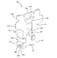
- FIG. 1 is a perspective view showing a state in which the board connector of Example 1 is fixed to a circuit board.
- 2 is a plan view showing part of the circuit board and part of the board connector of FIG. 1.
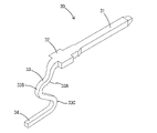
- FIG. 3 is a perspective view of a terminal fitting.
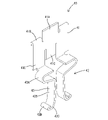
- FIG. 4 is a perspective view of the fixing member as seen from the outside in the left-right direction.
- FIG. 5 is a perspective view of the fixing member viewed from the inside in the left-right direction.
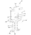
- FIG. 6 is a perspective view of the support member viewed from the outside in the left-right direction.
- FIG. 7 is a perspective view of the support member viewed from the inside in the left-right direction.
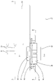
- FIG. 8 is a cross-sectional view corresponding to AA in FIG.
- FIG. 9 is a cross-sectional view corresponding to AA in FIG. 2 showing a state in which the board connector is fixed to the circuit board.
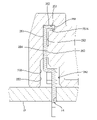
- 10 is a cross-sectional view corresponding to BB in FIG. 2 showing a state in which the fixing member is in the temporary locking position.
- FIG. 11 is a cross-sectional view corresponding to BB in FIG. 2 showing a state in which the fixing member is in the final locking position.
- 12 is a cross-sectional view corresponding to CC of FIG. 2 showing a state in which the fixing member is in the temporary locking position.
- 13 is a cross-sectional view corresponding to CC of FIG. 2 showing a state in which the fixing member is in the final locking position.
- FIG. 9 is a cross-sectional view corresponding to AA in FIG. 2 showing a state in which the board connector is fixed to the circuit board.
- 10 is a cross-sectional view corresponding to BB in FIG. 2 showing a state in which the fixing member is in the temporary locking
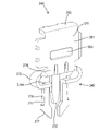
- FIG. 14 is a rear perspective view showing a state in which the board connector of Example 2 is fixed to the circuit board.
- FIG. 15 is a front perspective view showing a state in which the board connector is fixed to the circuit board.
- FIG. 16 is a perspective view of the fixing member seen from the outside in the left-right direction.
- FIG. 17 is a perspective view of the fixing member viewed from the inner side in the left-right direction.
- 18 is a side view of part of the board connector and part of the circuit board of FIG. 14 as seen from the front side.
- 19 is a cross-sectional view taken along line DD of FIG. 18.
- FIG. 20 is a cross-sectional view taken along the line EE of FIG. 19.
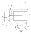
- FIG. 21 is a side sectional view showing a state before fixing the board connector to the circuit board.
- FIG. 22 is a side sectional view showing a state in which the board connector is fixed to the circuit board.
- the board connector of the present disclosure includes: (1) A board connector fixed to a circuit board, comprising terminal fittings and a housing to which the terminal fittings are assembled, comprising: The terminal fitting is a support receiving portion supported by the housing; a connecting portion connected to the circuit board; an elastic portion that is provided between the support receiving portion and the connection portion and that is elastically deformable; has The connecting portion is pressed against the circuit board based on the restoring force of the elastically deformed elastic portion. According to the configuration of the present disclosure, the connecting portion of the terminal fitting is pressed against the circuit board based on the restoring force of the elastically deformed elastic portion and connected to the circuit board.
- a fixing member is provided that is attached directly to the housing or via another member, is fixed to the circuit board, and fixes the housing to the circuit board, and the fixing member is directly attached to the housing or attached to the other member. and a fixing portion inserted into a hole provided in the circuit board and fixed, wherein the fixing portion is inserted into the hole and is a pair of elastically deformable hooks. It is preferable that the pair of hooking pieces are elastically deformed in the direction of approaching each other during the insertion process, and are fixed by hooking on the edge of the hole based on the restoring force.
- the fixing member for fixing the housing to the circuit board is fixed to the housing by utilizing the restoring force of the elastic deformation of the pair of hooking pieces, so fixing by soldering or the like is unnecessary. . Therefore, the board connector can be easily removed from the circuit board by elastically deforming the pair of hooking pieces to remove the fixing member from the hole.
- a support member that is attached to the housing and supports the fixing member, the support member having a through portion that penetrates the hole and protrudes in a direction opposite to the housing; is provided with a pressure-receiving surface facing the circuit board side, and the hooking piece is adapted to connect the circuit board and the pressure-receiving part of the penetrating portion based on a restoring force due to elastic deformation of the hooking piece. It is preferred to contact the surface. According to this configuration, the hooking piece contacts the circuit board and the pressure-receiving surface of the through portion based on the restoring force of elastic deformation, thereby moving the supporting member away from the circuit board (opposite side to the housing). can be suppressed.
- the housing to which the support member is attached is pressed against the circuit board, and the connecting portions of the terminal fittings are pressed against the circuit board.
- a plurality of terminal fittings be assembled in the housing along the alignment direction, and that the fixing member be provided at a position overlapping the plurality of connection portions in the alignment direction. According to this configuration, it is easier to ensure the contact pressure of the terminal fittings with respect to the circuit board, and the housing is less likely to tilt with respect to the circuit board, as compared with the configuration in which the fixing member is provided at a position shifted from the alignment direction.
- FIG. 1 A first embodiment embodying the board connector of the present disclosure will be described with reference to FIGS. 1 to 13.
- FIG. 1 the directions shown in FIGS. 1 and 3 to 13 are defined as upward and downward as they are.
- the right and left directions shown in FIGS. 1 to 4, 6, and 8 to 11 are defined as forward and rearward, respectively.
- 1 to 3 and 8 to 13 are defined as right and left, respectively.
- a board connector 10 (hereinafter also referred to simply as a connector 10) of the first embodiment is installed on a plate surface (front surface) of a circuit board 12, as shown in FIGS.
- the connector 10 includes a housing 20 , a plurality of terminal fittings 30 , a pair of fixing members 40 and a pair of supporting members 50 .
- the housing 20 can be fitted to a mating housing (not shown).
- the fixing member 40 and the supporting member 50 are provided on both left and right sides of the housing 20, respectively.
- the support member 50 is attached to the housing 20 and supports the fixed member 40 .
- the fixing member 40 is attached to the housing 20 via the support member 50 and fixed to the circuit board 12 to fix the housing 20 to the circuit board 12 .
- the housing 20 is made of synthetic resin, for example. As shown in FIGS. 1 and 8, the housing 20 has a rectangular tube-shaped receptacle 21 that opens forward. As shown in FIG. 8 , the hood portion 21 has a back wall 22 along the vertical direction and a fitting portion 23 projecting forward from the outer edge of the back wall 22 . As shown in FIG. 8, the back wall 22 is provided with a plurality of back wall holes 24 (only one is shown in FIG. 8) that penetrates in the front-rear direction. The terminal fittings 30 are press-fitted into the back wall holes 24 of the back wall 22 .
- the fitting portion 23 has a rectangular tubular shape and can be fitted to a mating housing (not shown).
- fixed grooves 60 to which the support members 50 are attached are provided on the left and right sides of the rear end side of the hood portion 21 .
- the fixed groove 60 is recessed inward in the left-right direction (toward the other fixed groove 60).
- the support member 50 is inserted into the fixed groove 60 from above.
- the fixed groove 60 has a first groove 61, a second groove 62, and a third groove 63, as shown in FIGS.
- the fixed grooves 60 are provided in order of a first groove 61, a second groove 62, and a third groove 63 from the left-right direction inner side (the other fixed groove 60 side) toward the left-right direction outer side.
- the first groove 61 is open in the vertical direction and recessed inward in the left-right direction (toward the other fixed groove 60).
- the second groove 62 has a larger width in the front-rear direction than the first groove 61 .
- the second groove 62 is provided in a stepped manner on the outer side in the left-right direction with respect to the first groove 61 .
- the third groove 63 has a larger width in the front-rear direction than the first groove 61 and a smaller width in the front-rear direction than the second groove 62 .
- the third groove 63 is provided in a stepped manner on the outer side in the left-right direction with respect to the second groove 62 .
- the upper ends of the front and rear walls of the third groove 63 are provided with recesses 64 that are recessed downward.
- the terminal fitting 30 is configured as a male terminal fitting.
- the terminal metal fitting 30 is made of a conductive metal and has a shape extending elongated like a tab.
- the terminal fitting 30 has a tab portion 31 , a support receiving portion 32 , an elastic portion 33 and a connection portion 34 .
- the tab portion 31 extends in the front-rear direction.
- the tab portion 31 is connected to a mating terminal (female terminal fitting).
- the support receiving portion 32 is connected to the rear end of the tab portion 31 .
- the support receiving portion 32 is wider in the left-right direction than other portions of the terminal fitting 30 .
- the support receiving portion 32 is press-fitted into the back wall hole 24 of the housing 20 and supported by the housing 20 .
- the elastic portion 33 extends from the rear end of the support receiving portion 32 .
- the elastic portion 33 is provided between the support receiving portion 32 and the connecting portion 34 and is elastically deformable.
- the elastic portion 33 includes a first bent portion 33A, a second bent portion 33B, and a third bent portion 33C.
- the first bent portion 33A extends downward from the rear end of the support receiving portion 32 .
- the first bent portion 33A is bent so as to be convex forward and downward.
- the second bent portion 33B extends downward from the rear end of the first bent portion 33A.
- the second bent portion 33B is bent so as to protrude rearward.
- the third bent portion 33C extends forward and downward from the lower end of the second bent portion 33B.
- the third bent portion 33C is bent forward to be convex.
- the elastic portion 33 is elastically deformable such that, for example, the first bent portion 33A, the second bent portion 33B, and the third bent portion 33C bend inward.
- the connecting portion 34 extends rearward and downward from the lower end of the elastic portion 33 (specifically, the third bent portion 33C).
- the connecting portion 34 is electrically connected to a conductive portion (not shown) of the circuit board 12 .
- the connecting portion 34 is pressed against the circuit board 12 based on the restoring force of the elastically deformed elastic portion 33 .
- the support member 50 is made of metal, for example, and is integrally formed.
- the support member 50 has an assembly portion 51 and a through portion 52 .
- the assembly portion 51 is a portion that is assembled to the housing 20 .
- the assembly portion 51 is a constituent part on the upper end side of the support member 50 .
- the assembly portion 51 is formed in a plate shape.
- the assembling portion 51 is provided with hooking pieces 51A that protrude from the vicinity of the central portion in the vertical direction to both the front and rear sides.
- the assembling portion 51 is provided with a folded portion 51B that extends from the upper side of the hooking piece 51A to both front and rear sides and is bent so as to be folded back.
- an upper edge portion 51C projecting upward is provided at a position sandwiched between the pair of folded portions 51B.
- a through hole 51 ⁇ /b>D is provided in the center of the assembly portion 51 so as to penetrate in the left-right direction.
- the through hole 51D has a square shape.
- a lower edge of the through hole 51D is provided with a bent piece 51E that is bent inward in the left-right direction (the side opposite to the side where the folded portion 51B is folded back).
- a bulging portion 51F that bulges inward in the left-right direction (the same side as the bent side of the bent piece 51E) is provided between the upper edge portion 51C and the through hole 51D.
- the bulging portion 51F is formed, for example, by forming a notch extending in the left-right direction and then punching it inward in the left-right direction.
- the penetrating part 52 is a component on the lower end side of the support member 50 .
- the penetrating portion 52 has a pocket shape recessed downward.
- the penetrating portion 52 penetrates the hole 14 of the circuit board 12 and projects to the side opposite to the housing 20 .
- the penetrating portion 52 has a first plate 53 and a second plate 54 .
- the first plate 53 and the second plate 54 face each other in the left-right direction.
- Belt-like arm portions 53A are provided at both front and rear ends of the first plate 53, respectively.
- the arm portion 53 ⁇ /b>A wraps around to the opposite surface of the second plate 54 (the surface opposite to the first plate 53 ) and supports the second plate 54 .
- the front and rear ends of the lower edge of the first plate 53 and the front and rear ends of the lower edge of the second plate 54 are connected by pressure receiving portions 55A, respectively.
- the pressure receiving portion 55A is provided at the projecting end portion of the through portion 52 .
- the upper surface of the pressure receiving portion 55A serves as a pressure receiving surface 55B facing the lower surface side of the circuit board 12 when the support member 50 is assembled to the circuit board 12 .
- a bridge portion 55C is provided to bridge the pair of pressure receiving portions 55A.
- the upper end of the first plate 53 is provided with a bent portion 55 that is bent outward in the left-right direction (the side opposite to the second plate 54).
- the support member 50 is inserted, for example, into the fixed groove 60 from above.
- the support member 50 is fixed in the fixing groove 60, as shown in FIGS.
- the hooking piece 51A is press-fitted into the second groove 62 .
- the folded portion 51B is arranged inside the recess 64 .
- the folded portion 51B can come into contact with the bottom surface (lower surface) of the concave portion 64 .
- the bent piece 51E and the bulging portion 51F are arranged inside the first groove 61 .
- the pressure receiving surface 55B faces upward (toward the circuit board 12 when assembled to the circuit board 12).
- the fixing member 40 is made of metal and is integrally formed.
- the fixing member 40 has a mounting portion 41 and a fixing portion 42 .
- the attachment portion 41 is a portion attached to the housing 20 via the support member 50 .
- the attachment portion 41 constitutes the upper end portion of the fixing member 40 .
- the mounting portion 41 is formed in a plate shape.
- An upper plate portion 41A projecting upward in the shape of a rectangular plate is provided at the center of the upper edge of the mounting portion 41 in the front-rear direction.
- First folded pieces 41B are provided on both front and rear sides of the upper plate portion 41A of the mounting portion 41, respectively.
- the first folded piece 41B extends upward and is bent to be folded back inward in the left-right direction (toward the other fixed member 40 when assembled to the housing 20).
- a lower plate portion 41 ⁇ /b>C projecting downward in the shape of a rectangular plate is provided at the center of the lower edge of the mounting portion 41 in the front-rear direction.
- a second folded piece 41D is provided at the lower end of the lower plate portion 41C so as to be folded back inward in the left-right direction (the same side as the folded side of the first folded piece 41B).
- Side plate portions 41E are provided on both front and rear sides of the lower plate portion 41C at the lower edge of the mounting portion 41, respectively.
- the fixing part 42 is inserted into the hole 14 provided in the circuit board 12 and fixed.
- the fixed portion 42 has a pair of hooking pieces 43 .
- the hooking piece 43 is elastically deformable.
- the hooking piece 43 is inserted into the hole 14 of the circuit board 12 .
- the hooking piece 43 includes a base end portion 43A, a deformed portion 43B, and a hooking portion 43C.
- the base end portion 43A once extends laterally outward (opposite to the folded side of the first folded piece 41B) from the lower end of the side plate portion 41E, and projects outward in the front-rear direction (opposite side to the hooking piece 43 on the other side).
- the deformation portion 43B extends downward from the tip (lower end) of the base end portion 43A.
- 43 C of hook parts are extended from the front-end
- the hooking portion 43C is curved outward in the front-rear direction (the side opposite to the other hooking piece 43) and protrudes downward.
- a third folded piece 43D that folds upward is provided at the tip of the hook portion 43C.
- the fixing member 40 is assembled to the supporting member 50 as shown in FIGS. 2, 10, 12 and the like. Both the left and right edges of the mounting portion 41 are sandwiched in the left-right direction by the laterally outer surface of the assembly portion 51 (the side where the folded portion 51B is folded back) and the folded portion 51B. This allows the fixing member 40 to move vertically relative to the supporting member 50 .
- the fixing portion 42 (specifically, the pair of hooking pieces 43 ) is arranged inside the through portion 52 .
- the fixing member 40 is displaced with respect to the support member 50 between a temporary locking position and a full locking position.
- the fixing member 40 shown in FIGS. 10 and 12 is positioned at the temporary locking position.
- the second folded piece 41D is inside the bulging portion 51F. The upward movement of the second folded piece 41D is restricted by interfering with the upper edge 51G of the bulging portion 51F (the upper edge of the notch formed when forming the bulging portion 51F).
- the fixing member 40 is displaced to the final locking position by pushing downward from the temporary locking position. For example, by pressing the upper plate portion 41A downward, the fixing member 40 is displaced from the temporary locking position to the final locking position.
- the fixing member 40 shown in FIGS. 11 and 13 is located at the final locking position.
- the lower plate portion 41C of the fixing member 40 is pushed outward in the left-right direction (opposite side to the bulging direction of the bulging portion 51F) from the bulging portion 51F via the second folded piece 41D, and is flexed outward in the left-right direction. nothing.
- the second folded piece 41D climbs over the bulging portion 51F and is hooked to the upper edge 51H of the through hole 51D from below.
- the first folded piece 41B of the fixed member 40 faces the upper edge of the support member 50 including the folded portion 51B so as to be able to contact from above.
- the fixing member 40 is fixed to the housing 20 via the support member 50 .
- the board connector 10 is prepared. Specifically, the terminal fitting 30 , the support member 50 and the fixing member 40 are attached to the housing 20 . At this time, the fixing member 40 is positioned at the temporary locking position (see FIGS. 10 and 12). As shown in FIG. 8, the terminal fitting 30 is in a free state, and the connecting portion 34 protrudes downward from the housing 20. As shown in FIG. A through portion 52 of the support member 50 protrudes downward from the housing 20 .
- the board connector 10 is placed on the upper surface of the circuit board 12 .
- the through portion 52 of the support member 50 passes through the hole 14 .
- the through portion 52 protrudes downward from the lower surface of the circuit board 12 .
- a pressure receiving surface 55 ⁇ /b>B of the through portion 52 faces the lower surface of the circuit board 12 .
- the bent piece 51 ⁇ /b>E and the bent portion 55 of the support member 50 are in contact with the upper surface of the circuit board 12 .
- the fixing member 40 is in the temporary locking position as shown in FIGS. 10 and 12 .
- the pair of hooking pieces 43 are in a free state.
- the fixing member 40 is displaced from the temporary locking position to the final locking position.
- a hooking portion 43C of the hooking piece 43 contacts the pressure receiving surface 55B.
- the pair of hooking pieces 43 are elastically deformed in the direction of approaching each other during the insertion process into the hole 14 .
- the tip of the hooking piece 43 (the third folded piece 43D and its base end portion) enters between the lower surface of the circuit board 12 (the edge 16 of the hole 14) and the pressure receiving portion 55A.
- the pair of hooking pieces 43 (hooking portions 43C) are fixed by hooking on the lower edge portion 16 of the hole 14 based on the restoring force.
- the hooking piece 43 causes the lower surface of the circuit board 12 (the lower edge 16 of the hole 14 ) and the pressure-receiving surface 55 ⁇ /b>B of the penetrating portion 52 to move toward each other based on the restoring force due to the elastic deformation of the hooking piece 43 . come into contact with That is, the lower surface of the circuit board 12 (the lower edge 16 of the hole 14) and the pressure receiving surface 55B of the through portion 52 are stretched. In this manner, the hooking piece 43 contacts the lower surface of the circuit board 12 and the pressure receiving surface 55B of the through portion 52 based on the restoring force of elastic deformation, thereby moving the support member 50 away from the circuit board 12 (housing direction). 20). Therefore, the housing 20 to which the support member 50 is attached is pressed against the circuit board 12 , and the connection portions 34 of the terminal fittings 30 are pressed against the circuit board 12 .
- the connecting portion 34 of the terminal fitting 30 is pressed against the circuit board 12 based on the restoring force of the elastically deformed elastic portion 33 . Therefore, the connecting portion 34 can be easily removed from the circuit board 12 by releasing the fixed state by the fixing member 40 . As a result, the board connector 10 can be easily repaired.
- the elastic portion 33 bends, thereby allowing the connection portion 34 to wipe the circuit board 12 . Since soldering or press-fitting is not used to connect the terminal fittings 30 to the circuit board 12, damage to the circuit board 12 can also be reduced.
- the pair of hooking pieces 43 are elastically deformed in the direction of approaching each other during the insertion process, and are fixed by hooking on the edge 16 of the hole 14 based on the restoring force.
- the fixing member 40 is fixed to the housing 20 by utilizing the restoring force of the elastic deformation of the pair of hooking pieces 43, so fixing by soldering or the like is unnecessary. Therefore, the connector 10 can be easily removed from the circuit board 12 by elastically deforming the pair of hooking pieces 43 to remove the fixing member 40 from the hole 14 .
- the plurality of terminal fittings 30 are assembled in the housing 20 so as to line up along the alignment direction (horizontal direction).
- the pair of fixing members 40 are provided at positions overlapping the plurality of connection portions 34 in the alignment direction (horizontal direction) of the plurality of terminal fittings 30 . That is, the pair of fixing members 40 is positioned on an extension line of the alignment axis of the plurality of connection portions 34 (straight line passing through the plurality of connection portions 34 and parallel to the left-right direction).
- the pair of fixing members 40 are positioned to overlap mainly the elastic portions 33 and the connection portions 34 of the plurality of terminal fittings 30 in the alignment direction (horizontal direction).
- the connecting portion 34 of the terminal fitting 30 is pressed against the circuit board 12 based on the restoring force of the elastically deformed elastic portion 33 and is connected to the circuit board 12 . Therefore, it can be easily removed from the circuit board 12 as compared with connection by press fitting, soldering, or the like.
- the pair of hooking pieces 43 are elastically deformed in the direction of approaching each other during the insertion process, and are fixed by hooking on the edge 16 of the hole 14 based on the restoring force.
- the fixing member 40 for fixing the housing 20 to the circuit board 12 is fixed to the housing 20 using the restoring force of the elastic deformation of the pair of hooking pieces 43, so fixing by soldering or the like is unnecessary. becomes. Therefore, the board connector 10 can be easily removed from the circuit board 12 by elastically deforming the pair of hooking pieces 43 to remove the fixing member 40 from the hole 14 .
- the hooking piece 43 contacts the circuit board 12 and the pressure receiving surface 55B of the penetrating portion 52 based on the restoring force due to the elastic deformation of the hooking piece 43 .
- the hooking piece 43 contacts the circuit board 12 and the pressure receiving surface 55B of the through portion 52 based on the restoring force of elastic deformation, thereby moving the support member 50 away from the circuit board 12 (in contrast to the housing 20). opposite side). Therefore, the housing 20 to which the support member 50 is attached is pressed against the circuit board 12 , and the connection portions 34 of the terminal fittings 30 are pressed against the circuit board 12 .
- the fixing member 40 is provided at a position overlapping the plurality of connecting portions 34 in the alignment direction of the plurality of terminal fittings 30 . This makes it easier to secure contact pressure of the terminal fittings 30 against the circuit board 12 and makes it difficult for the housing 20 to tilt with respect to the circuit board 12, as compared with a configuration in which the fixing member 40 is provided at a position shifted from the alignment direction. .
- Example 2 14 to 22 are drawings for explaining the board connector of Example 2.
- FIG. Example 2 is different from Example 1 in the configuration of the fixing member, in that no supporting member is provided.
- Other configurations are the same as those of the first embodiment, and detailed description thereof will be omitted.
- FIG. 14 to 22 A second embodiment embodying the board connector of the present disclosure will be described with reference to FIGS. 14 to 22.
- the vertical directions shown in FIGS. 14 to 22 are defined as upward and downward.
- the right and left sides shown in FIGS. 14, 19, 21 and 22 are defined as forward and rearward, respectively.
- 15, 18 and 20 are defined as left and right as they are.
- a board connector 210 (hereinafter also referred to simply as a connector 210) of the second embodiment is installed on the board surface (front surface) of the circuit board 12, as shown in FIGS.
- the connector 210 includes a housing 220 , terminal fittings 30 and fixing members 240 .
- the housing 220 can be fitted to a mating housing (not shown).
- the housing 220 is made of synthetic resin, for example. As shown in FIG. 15, the housing 220 has a rectangular tube-shaped receptacle 221 that opens forward. As shown in FIG. 21 , the hood portion 221 has a back wall 222 along the vertical direction and a fitting portion 223 projecting forward from the outer edge of the back wall 222 . As shown in FIG. 21, the back wall 222 is provided with a plurality of back wall holes 224 (only one is shown in FIG. 21) passing therethrough in the front-rear direction. Terminal fittings 30 are attached by being press-fitted into respective back wall holes 224 of back wall 222 .
- the fitting portion 223 has a rectangular tubular shape and can be fitted to a mating housing (not shown).
- fixing grooves 250 to which fixing members 240 are attached are provided on both left and right sides of the rear end side of the hood portion 21 .
- the fixed groove 250 is open forward and downward.
- the fixing member 240 is inserted into the fixing groove 250 from the front side.
- the fixed groove 250 has an upper groove 251, a central groove 252, and a lower groove 253, as shown in FIGS.
- the upper groove 251 constitutes the upper end portion of the fixed groove 250 .
- the upper groove 251 extends in the front-rear direction and opens forward.
- the upper groove 251 extends laterally inward (toward the other fixed groove 250 ) from the upper end of the central groove 252 and is wider than the central groove 252 in the lateral direction.
- the central groove 252 constitutes the central portion of the fixed groove 250 in the vertical direction.
- the central groove 252 is vertically long and open forward.
- a housing-side convex portion 254 that protrudes laterally outward (the side opposite to the other fixed groove 250) is provided on the inner wall surface of the central groove 252 (on the side of the other fixed groove 250).
- the lower groove 253 constitutes the lower end portion of the fixed groove 250 .
- the lower groove 253 is wider in the horizontal direction than the upper groove 251 and the central groove 252 .
- the terminal fitting 30 has the same configuration as the terminal fitting 30 of the first embodiment.
- the terminal fitting 30 is configured as a male terminal fitting.
- the support receiving portion 32 is press-fitted into the back wall hole 224 of the housing 220 and supported by the housing 220 .
- the connecting portion 34 is pressed against the circuit board 12 based on the restoring force of the elastically deformed elastic portion 33 .
- the fixing member 240 is made of metal and is integrally formed. As shown in FIG. 16, the pair of fixing members 240 are attached to both left and right sides of the housing 220, respectively. The fixing member 240 is fixed to the circuit board 12 and fixes the housing 220 to the circuit board 12 .
- the fixing member 240 has a mounting portion 241 and a fixing portion 242, as shown in FIGS.
- the attachment portion 241 is a portion attached to the housing 220 .
- the attachment portion 241 has a plate portion 261 and an upper edge portion 262 .
- the plate portion 261 has a plate shape along the vertical direction and the horizontal direction.
- a fixing member-side convex portion 263 is provided that protrudes inward in the left-right direction (toward the other fixing member 240 when attached to the housing 220).
- the upper edge portion 262 extends from the upper end of the plate portion 261 inward in the left-right direction (the same side as the projecting direction of the fixing member-side convex portion 263).
- a pair of protruding pieces 264 that protrude in the same direction as the extending direction of the upper edge portion 262 are provided at the tip of the upper edge portion 262 .
- the pair of projecting pieces 264 are spaced apart in the front-rear direction.
- the fixing part 242 is inserted into the hole 14 provided in the circuit board 12 and fixed.
- the fixing portion 242 includes a pair of hooking pieces 271 and an extending portion 272, as shown in FIGS.
- the hooking piece 271 includes a base end portion 274 , a deformation portion 275 and a hooking portion 276 .
- the base end portion 274 extends downward from the lower end of the mounting portion 241 (specifically, the plate portion 261).
- the deformable portion 275 once extends inward in the left-right direction (on the side where the upper edge portion 262 extends), and is bent outward in the front-rear direction (on the side opposite to the other deformable portion 275).
- the hook portion 276 extends downward from the tip (lower end) of the deformation portion 275 .
- a slit 275A is provided between the distal end (lower end) of the deformation portion 275 and the base end (upper end) of the hook portion 276 .
- a wide portion 277 is provided at the tip of the hook portion 276 and is wider than the other portion (the portion closer to the proximal end than the tip). The lower edge of the wide portion 277 is inclined inward in the front-rear direction (toward the hook portion 276 on the other side) downward.
- the extending portion 272 is provided between the pair of hooking pieces 271 .
- the extending portion 272 extends downward from between the pair of hooking pieces 271 at the lower end of the mounting portion 241 (specifically, the plate portion 261).
- the extension portion 272 once extends downward, bends inward in the left-right direction (on the extension side of the upper edge portion 262), and further extends downward.
- the tip of the extending portion 272 is positioned between the pair of hooking pieces 271 .
- the extending portion 272 interferes with the hooking piece 271 bent inward in the front-rear direction (toward the other hooking piece 271 side), thereby suppressing excessive bending of the hooking piece 271 .
- the fixing member 240 is attached to the housing 220 as shown in FIGS. 18 to 20 by being press-fitted into the fixing groove 250 from the front.
- the upper edge 262 is press-fitted into the upper groove 251 .
- the pair of projecting pieces 264 contact a wall surface (back surface) 251A on the inner side of the upper groove 251 in the left-right direction (on the side of the other upper groove 251).
- the plate portion 261 is press-fitted into the central groove 252 .
- the fixing member-side protrusion 263 contacts the housing-side protrusion 254 .
- the fixing part 242 is arranged in the lower groove 253 .
- the lower end side of the fixing member 240 protrudes downward from the lower end surface of the housing 220, as shown in FIG.
- the board connector 210 is prepared. Specifically, as shown in FIG. 21, the terminal fitting 30 and the fixing member 240 are attached to the housing 220 .
- the board connector 210 is placed on the upper surface of the circuit board 12 by inserting the pair of hooking pieces 271 into the holes 14 as shown in FIG.
- the pair of hooking pieces 271 are elastically deformed in the direction of approaching each other during the insertion process into the hole 14 .
- the lower edge of the wide portion 277 is guided by the hole 14 and enters the hole 14 .
- the wide portion 277 penetrates through the hole 14 .
- the pair of hooking pieces 271 are fixed by hooking on the lower edge 16 of the hole 14 based on the restoring force.
- the fixing member 240 is prevented from coming out of the hole 14 by the wide portion 277 being caught by the lower edge 16 of the hole 14 .
- the connecting portion 34 of the terminal fitting 30 is pressed against the circuit board 12 based on the restoring force of the elastically deformed elastic portion 33, as shown in FIG. Therefore, the connecting portion 34 can be easily removed from the circuit board 12 by releasing the fixed state by the fixing member 240 .
- the pair of hooking pieces 271 are elastically deformed in the direction of approaching each other during the insertion process, and are fixed by hooking on the edge 16 of the hole 14 based on the restoring force.
- the fixing member 240 is fixed to the housing 220 by utilizing the restoring force of the elastic deformation of the pair of hooking pieces 271, so fixing by soldering or the like is unnecessary. Therefore, the connector 210 can be easily removed from the circuit board 12 by elastically deforming the pair of hooking pieces 271 to remove the fixing member 240 from the hole 14 .
- the terminal fitting 30 is configured as a male terminal fitting, but may be a female terminal fitting.
- the terminal fitting 30 has three bent portions (the first bent portion 33A, the second bent portion 33B, and the third bent portion 33C). is not limited to For example, it may be configured to be bent like a crank.
- the pair of fixing members 240 may be provided at positions overlapping the plurality of connecting portions 34 in the alignment direction (horizontal direction) of the plurality of terminal fittings 30 .
Landscapes
- Coupling Device And Connection With Printed Circuit (AREA)
Priority Applications (2)
| Application Number | Priority Date | Filing Date | Title |
|---|---|---|---|
| US18/290,275 US20240275088A1 (en) | 2021-05-21 | 2022-03-23 | Board connector |
| CN202280032292.XA CN117242649A (zh) | 2021-05-21 | 2022-03-23 | 基板用连接器 |
Applications Claiming Priority (2)
| Application Number | Priority Date | Filing Date | Title |
|---|---|---|---|
| JP2021-085922 | 2021-05-21 | ||
| JP2021085922A JP2022178837A (ja) | 2021-05-21 | 2021-05-21 | 基板用コネクタ |
Publications (1)
| Publication Number | Publication Date |
|---|---|
| WO2022244452A1 true WO2022244452A1 (ja) | 2022-11-24 |
Family
ID=84141534
Family Applications (1)
| Application Number | Title | Priority Date | Filing Date |
|---|---|---|---|
| PCT/JP2022/013348 Ceased WO2022244452A1 (ja) | 2021-05-21 | 2022-03-23 | 基板用コネクタ |
Country Status (4)
| Country | Link |
|---|---|
| US (1) | US20240275088A1 (https=) |
| JP (2) | JP2022178837A (https=) |
| CN (1) | CN117242649A (https=) |
| WO (1) | WO2022244452A1 (https=) |
Families Citing this family (1)
| Publication number | Priority date | Publication date | Assignee | Title |
|---|---|---|---|---|
| GB2638110A (en) * | 2022-07-28 | 2025-08-20 | Aptiv Tech Ltd | An electrical connector having a ferrule with clinched arms for shielded functionality |
Citations (3)
| Publication number | Priority date | Publication date | Assignee | Title |
|---|---|---|---|---|
| JPS55149270U (https=) * | 1979-04-13 | 1980-10-27 | ||
| JP2000133342A (ja) * | 1998-10-20 | 2000-05-12 | Hirose Electric Co Ltd | フローティング電気コネクタ |
| JP2005285654A (ja) * | 2004-03-30 | 2005-10-13 | Japan Aviation Electronics Industry Ltd | コネクタ固定部材とそれを用いたコネクタ |
Family Cites Families (2)
| Publication number | Priority date | Publication date | Assignee | Title |
|---|---|---|---|---|
| US6616479B1 (en) * | 2002-03-08 | 2003-09-09 | Hon Hai Precision Ind. Co., Ltd. | Retention device for separable connection |
| KR101947440B1 (ko) * | 2016-02-04 | 2019-05-10 | 주식회사 아모텍 | 클립형 컨택터 및 이를 포함하는 보호장치 |
-
2021
- 2021-05-21 JP JP2021085922A patent/JP2022178837A/ja active Pending
-
2022
- 2022-03-23 WO PCT/JP2022/013348 patent/WO2022244452A1/ja not_active Ceased
- 2022-03-23 CN CN202280032292.XA patent/CN117242649A/zh active Pending
- 2022-03-23 US US18/290,275 patent/US20240275088A1/en active Pending
-
2024
- 2024-07-31 JP JP2024124880A patent/JP7737086B2/ja active Active
Patent Citations (3)
| Publication number | Priority date | Publication date | Assignee | Title |
|---|---|---|---|---|
| JPS55149270U (https=) * | 1979-04-13 | 1980-10-27 | ||
| JP2000133342A (ja) * | 1998-10-20 | 2000-05-12 | Hirose Electric Co Ltd | フローティング電気コネクタ |
| JP2005285654A (ja) * | 2004-03-30 | 2005-10-13 | Japan Aviation Electronics Industry Ltd | コネクタ固定部材とそれを用いたコネクタ |
Also Published As
| Publication number | Publication date |
|---|---|
| JP2024138198A (ja) | 2024-10-07 |
| JP7737086B2 (ja) | 2025-09-10 |
| JP2022178837A (ja) | 2022-12-02 |
| CN117242649A (zh) | 2023-12-15 |
| US20240275088A1 (en) | 2024-08-15 |
Similar Documents
| Publication | Publication Date | Title |
|---|---|---|
| CN102292874B (zh) | 板对板连接器 | |
| CN100414779C (zh) | 一种连接组件 | |
| US9190750B2 (en) | Board-to-board connector | |
| JP5647434B2 (ja) | 嵌合完了検知スイッチ付きコネクタ | |
| JP5457595B1 (ja) | コネクタおよび端子 | |
| JP5956071B2 (ja) | 接続端子 | |
| JPH07335299A (ja) | リセプタクル端子 | |
| CN102687346A (zh) | 电端子 | |
| JP6083957B2 (ja) | コネクタ及びコネクタ製造方法 | |
| JP7297622B2 (ja) | フローティングコネクタ | |
| CN110247213B (zh) | 中间电连接器及电连接器组装体 | |
| JP7438076B2 (ja) | 相手電気コネクタ及び電気コネクタ組立体 | |
| JP5704031B2 (ja) | コネクタ | |
| JP2005285654A (ja) | コネクタ固定部材とそれを用いたコネクタ | |
| CN113594807B (zh) | 射频连接器 | |
| JP7737086B2 (ja) | 基板用コネクタ | |
| CN101305502A (zh) | 安装于电路板上的板对板连接器 | |
| CN109980413A (zh) | 扁平型导体用电连接器 | |
| JP6095182B2 (ja) | コンタクト及びコネクタ | |
| CN108574164B (zh) | 电连接器及电连接器组装体 | |
| CN116169494B (zh) | 固定构件及基板用连接器 | |
| US12368257B2 (en) | Terminal fitting and connector with deformation-suppressible elastic contact portion | |
| JP5123802B2 (ja) | コネクタ | |
| WO2022196269A1 (ja) | カードエッジコネクタ | |
| CN221994796U (zh) | 扁平型导体用电连接器以及扁平型导体用电连接器组装体 |
Legal Events
| Date | Code | Title | Description |
|---|---|---|---|
| 121 | Ep: the epo has been informed by wipo that ep was designated in this application |
Ref document number: 22804370 Country of ref document: EP Kind code of ref document: A1 |
|
| WWE | Wipo information: entry into national phase |
Ref document number: 202280032292.X Country of ref document: CN |
|
| WWE | Wipo information: entry into national phase |
Ref document number: 18290275 Country of ref document: US |
|
| NENP | Non-entry into the national phase |
Ref country code: DE |
|
| 122 | Ep: pct application non-entry in european phase |
Ref document number: 22804370 Country of ref document: EP Kind code of ref document: A1 |