WO2022244188A1 - 空気調和装置の室内ユニット - Google Patents
空気調和装置の室内ユニット Download PDFInfo
- Publication number
- WO2022244188A1 WO2022244188A1 PCT/JP2021/019168 JP2021019168W WO2022244188A1 WO 2022244188 A1 WO2022244188 A1 WO 2022244188A1 JP 2021019168 W JP2021019168 W JP 2021019168W WO 2022244188 A1 WO2022244188 A1 WO 2022244188A1
- Authority
- WO
- WIPO (PCT)
- Prior art keywords
- refrigerant
- header
- heat transfer
- heat exchanger
- transfer tubes
- Prior art date
- Legal status (The legal status is an assumption and is not a legal conclusion. Google has not performed a legal analysis and makes no representation as to the accuracy of the status listed.)
- Ceased
Links
Images







Classifications
-
- F—MECHANICAL ENGINEERING; LIGHTING; HEATING; WEAPONS; BLASTING
- F24—HEATING; RANGES; VENTILATING
- F24F—AIR-CONDITIONING; AIR-HUMIDIFICATION; VENTILATION; USE OF AIR CURRENTS FOR SCREENING
- F24F1/00—Room units for air-conditioning, e.g. separate or self-contained units or units receiving primary air from a central station
- F24F1/0007—Indoor units, e.g. fan coil units
- F24F1/0059—Indoor units, e.g. fan coil units characterised by heat exchangers
Definitions
- the present disclosure relates to the structure of an indoor unit of an air conditioner that includes flat heat transfer tubes.
- a heat exchanger configured by flat heat transfer tubes includes a plurality of flat heat transfer tubes extending in the horizontal direction and a plurality of heat transfer tubes attached in contact with the flat heat transfer tubes.
- the indoor unit having the above heat exchanger includes a housing having an air inlet and an air outlet, a fan arranged inside the housing, and at least one heat exchanger arranged above the fan.
- the heat exchanger disclosed in Patent Document 1 is provided with a water-conducting member that is continuous with at least one of the flat heat transfer tubes and the fins, thereby suppressing the accumulation of condensed water generated inside the fins.
- a blocking wall having an L-shaped cross section is provided at the end of the flat heat transfer tube in the longitudinal direction of the cross section.
- the blocking wall covers the lower ends of the fins provided between the flat heat transfer tubes from the outside. Therefore, for example, even if the heat exchanger is tilted with the side where the condensate collects downward, the condensate will not drip onto the fan and the fan will not splash the water. It is configured.
- the heat exchanger of the indoor unit of the air conditioner functions as an evaporator in the case of cooling operation to cool the indoor air.
- Indoor air is sucked into the indoor unit by the fan, cooled by the heat exchanger, and then blown out into the room.
- dew condensation occurs on the surface of the heat exchanger.
- the condensed water drips from the heat exchanger and is sucked into the fan, the condensed water scatters inside the room. Therefore, it is necessary to prevent the condensed water from being drawn into the fan.
- Patent Document 1 dripping of condensed water onto the fan is suppressed by installing a water-conducting member between the heat exchanger and the fan. Further, in Patent Document 2, by installing a blocking wall at the end of the flat heat transfer tube on the lee side, dripping of the condensed water to the fan is suppressed.
- the present disclosure has been made to solve the above-described problems, and provides an air conditioner that suppresses dripping of condensed water to the fan and suppresses the cost and heat exchange performance of the heat exchanger.
- the object is to provide an indoor unit.
- An indoor unit of an air conditioner of the present disclosure includes a housing having an air intake port and an air outlet, a fan installed inside the housing, and a heat exchanger arranged above the fan,
- the heat exchanger includes a plurality of flat heat transfer tubes arranged in parallel with their tube axes crossing the vertical direction, a plurality of heat transfer fins attached between the plurality of flat heat transfer tubes, and the plurality of flat heat transfer tubes.
- a refrigerant header connected to the ends of the heat tubes for distributing the refrigerant to the plurality of flat heat transfer tubes or joining the refrigerant from the plurality of flat heat transfer tubes, wherein the refrigerant header has partition walls inside the plurality of headers.
- Each of the plurality of header inner spaces is connected to at least one flat heat transfer tube among the plurality of flat heat transfer tubes, and is the first header positioned highest among the plurality of header inner spaces.
- the inner space of the header is connected to a connecting pipe for inflow or outflow of the refrigerant to the refrigerant header and to the plurality of flat heat transfer tubes positioned vertically above the fan.
- the heat exchanger of the indoor unit of the air conditioner of the present disclosure can increase the temperature of the refrigerant flowing through the flat heat transfer tubes positioned vertically above the fan.
- the temperature difference between the passing air and the refrigerant in the part of the heat exchanger located above the fan becomes smaller, the amount of condensed water generated on the surface of the heat exchanger is reduced, and the amount of condensed water that drips onto the fan. can be suppressed.
- since no additional structure is added to the portion of the heat exchanger through which the air passes an increase in cost can be suppressed, and an increase in air pressure resistance can also be suppressed.
- FIG. 2 is a schematic diagram of the internal structure of the indoor unit 100 of the air conditioner according to Embodiment 1.
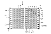
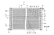
- FIG. 2 is a cross-sectional view of heat exchanger 5 of indoor unit 100 of the air conditioner according to Embodiment 1.
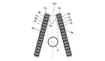
- FIG. 2 is an enlarged view for explaining the positional relationship between a heat exchanger 5 and a fan 4 in FIG. 1;
- FIG. 4 is a schematic diagram of temperature distributions of refrigerant flowing through a heat exchanger 5 and air flowing into the heat exchanger 5 of the indoor unit 100 of the air conditioner according to Embodiment 1.
- FIG. FIG. 4 is a cross-sectional view of a heat exchanger 5 of an indoor unit 100 of an air conditioner according to Embodiment 2;
- FIG. 10 is a schematic diagram of temperature distributions of a non-azeotropic refrigerant mixture flowing through a heat exchanger 5 and air flowing into the heat exchanger 5 of the indoor unit 100 of the air conditioner according to Embodiment 2;
- FIG. 11 is a cross-sectional view of a heat exchanger 5 of an indoor unit 100 of an air conditioner according to Embodiment 3;
- FIG. 11 is a cross-sectional view of a heat exchanger 5 of an indoor unit 100 of an air conditioner according to Embodiment 4;
- FIG. 9 is a partial enlarged view of the cross-sectional structure of the heat exchanger 5 in the hydrophilic treatment region 15 of FIG. 8;
- FIG. 11 is a schematic diagram of the internal structure of an indoor unit 500 of an air conditioner according to Embodiment 5.
- FIG. FIG. 11 is a cross-sectional view of a heat exchanger 505 of an indoor unit 500 of an air conditioner according to Embodiment 5.
- FIG. 1 is a schematic diagram of the internal structure of an indoor unit 100 of an air conditioner according to Embodiment 1.
- the indoor unit 100 of the air conditioner according to Embodiment 1 includes a housing 3 having an air inlet 1 and an air outlet 2, a fan 4, a heat exchanger 5, and a drain pan 6.
- the fan 4 is arranged inside the housing 3 and takes in indoor air from the air inlet 1 into the housing 3 by rotational driving.
- the air taken into the housing 3 passes through the heat exchanger 5 and is then blown into the room through the air outlet 2 .
- the air taken into the housing 3 exchanges heat with the refrigerant flowing inside the heat exchanger 5 when passing through the heat exchanger 5, and is cooled or heated.
- the air cooled or heated in the heat exchanger 5 is blown into the room from the outlet 2 to perform air conditioning.
- the fan 4 according to Embodiment 1 is a cross-flow fan, it is not particularly limited as long as it has a function of circulating air, such as a propeller fan.
- the heat exchanger 5 is composed of a plurality of heat exchangers 5a and 5b, is located upstream of the air passage with respect to the fan 4, faces the fan 4 with the fan 4 therebetween, and faces the fan 4. It is arranged so as to cover the upper part of the In the cross-sectional structure of the indoor unit 100 of the air conditioner shown in FIG. It is configured. Note that the two heat exchangers 5a and 5b may be collectively called the heat exchanger 5 in some cases.
- the drain pan 6 is arranged below the heat exchanger 5 and collects condensed water generated on the surface of the heat exchanger 5 .
- the drain pan 6 is arranged below the lower end portions of the heat exchangers 5a and 5b arranged at an angle.
- Heat exchanger 5 2 is a cross-sectional view of the heat exchanger 5 of the indoor unit 100 of the air conditioner according to Embodiment 1.
- FIG. The heat exchanger 5 shows a cross-sectional structure taken along line AA in FIG.
- the heat exchanger 5 includes multiple flat heat transfer tubes 7 , multiple heat transfer fins 8 , and multiple refrigerant headers 9 .
- a plurality of flat heat transfer tubes 7 are arranged side by side with their tube axes directed in a direction intersecting the vertical direction.
- the plurality of flat heat transfer tubes 7 are arranged with their tube axes extending in the horizontal direction, and are arranged in parallel at regular intervals.
- the tube axes of the plurality of flat heat transfer tubes 7 may be arranged not only in the horizontal direction but also inclined with respect to the horizontal direction.
- Each of the plurality of flat heat transfer tubes 7 is made of, for example, aluminum, and has at least one channel through which a refrigerant flows in a cross section that intersects the tube axis.
- Refrigerant headers 9a and 9b are connected to both ends of the plurality of flat heat transfer tubes 7.
- the refrigerant headers 9a and 9b may be collectively referred to as the refrigerant header 9 in some cases.
- the refrigerant header 9 receives the refrigerant flowing through the refrigeration cycle circuit and distributes the refrigerant to the plurality of flat heat transfer tubes 7 .
- each of the refrigerant headers 9a and 9b is partitioned to have at least one partition wall 10 inside and a plurality of header internal spaces 11 inside.
- connecting pipes 12 are provided in each of the refrigerant headers 9a and 9b.
- refrigerant flowing through the refrigerating cycle circuit flows into the connecting pipe 12, or refrigerant in the refrigerant header 9 flows out to the refrigerating cycle circuit.
- the refrigerant header 9 is made of, for example, aluminum, but the material is not particularly limited.
- the partition wall 10 is arranged inside at least one refrigerant header 9 , and the inside of the refrigerant header 9 is divided into a plurality of header internal spaces 11 by the partition wall 10 . At least one flat heat transfer tube 7 among the plurality of flat heat transfer tubes 7 is connected to the plurality of header internal spaces 11 .
- the material of the partition wall 10 is desirably the same as the material of the refrigerant header 9 in terms of assembly.
- connection pipe 12 is connected to at least one refrigerant header 9 and allows the refrigerant to flow in and out from the outside of the refrigerant header 9 .
- the material of the connection pipe 12 is desirably the same as the material of the refrigerant header 9 in terms of assembly.
- the heat transfer fins 8 are arranged between the plurality of flat heat transfer tubes 7 and in contact with each of the plurality of flat heat transfer tubes 7 so as to transfer heat.
- the heat transfer fins 8 are corrugated fins sandwiched between two flat heat transfer tubes 7 arranged side by side in parallel in the horizontal direction of FIG.
- the plurality of flat heat transfer tubes 7 and heat transfer fins 8 are connected by, for example, brazing.
- the form of connection is not particularly limited.
- the shape of the heat transfer fins 8 is corrugated, but plate-type fins, for example, may be arranged.
- FIG. 3 is an enlarged view explaining the positional relationship between the heat exchanger 5 and the fan 4 in FIG.
- the heat exchanger 5 according to Embodiment 1 is inclined with respect to the vertical direction upstream of the fan 4 , and its upper end portion 5 ⁇ /b>A is positioned vertically above the fan 4 .
- the flat heat transfer tube 7 closest to the vertical plane 201 passing through the rotation axis of the fan 4 is called the flat heat transfer tube 7A, and the plurality of flat heat transfer tubes 7 arranged in order from there in the direction of gravity are flat heat transfer tubes.
- the flat heat transfer tubes 7A, 7B and 7C are positioned above the fan 4 when 7B, 7C, 7D, 7E . . . As shown in FIG.
- the flat heat transfer tubes 7A, 7B and 7C located above the fan 4 are connected to the header inner space 11a among the plurality of header inner spaces 11a and 11c of the refrigerant header 9a.
- the header internal space 11a of the refrigerant header 9a may be called a first header internal space.
- the header internal space 11a has a smaller volume than the header internal space 11c and is arranged at the top of the header internal space 11c. Further, the header internal space 11a may be connected not only to the flat heat transfer tubes 7A, 7B, and 7C, but also to the flat heat transfer tube 7D that is detached from above the fan 4.
- the refrigerant header 9b is partitioned by a partition wall 10 and has a plurality of vertical header internal spaces 11b and 11d.
- the header internal space 11b of the refrigerant header 9b is larger in volume than the header internal space 11d located below.
- the header internal space 11a of one refrigerant header 9a is connected to the header internal space 11b of the other refrigerant header 9b by a plurality of flat heat transfer tubes 7A, 7B, 7C and 7D.
- the header internal space 11b of the other refrigerant header 9b includes a plurality of flat heat transfer tubes 7A, 7B, 7C, and 7D connected to the header internal space 11a of the one refrigerant header 9a, as well as a plurality of flat heat transfer tubes 7E, It is connected with 7F, 7G and 7H.
- a plurality of flat heat transfer tubes 7E, 7F, 7G and 7H are connected to the header inner space 11b of one refrigerant header 9a.
- the header internal space 11c positioned below one of the refrigerant headers 9a includes a plurality of flat heat transfer tubes 7E, 7F, 7G, and 7H connected to the header internal space 11b of the other refrigerant header 9b. It is connected to flat heat transfer tubes 7I, 7J and 7K.
- a plurality of flat heat transfer tubes 7I, 7J and 7K are connected to the header internal space 11d located below the other refrigerant header 9b.
- the header internal space 11d of the other refrigerant header 9b has a smaller volume than the header internal space 11b positioned above, and the connecting pipe 12 is connected thereto. Note that the header internal space 11d of the refrigerant header 9b may be called a second header internal space.
- the refrigerant flowing in from the connecting pipe 12 of one refrigerant header 9a travels between the refrigerant headers 9 via the plurality of flat heat transfer tubes 7. , and finally flows out from the connecting pipe 12 of the other refrigerant header 9b.
- the space 11 inside the header of the heat exchanger 5 has the function of gathering or distributing the refrigerant passing through the plurality of flat heat transfer tubes 7 therebetween, and also provides separation in the direction of gravity due to the difference in refrigerant density and specific gravity. .
- Embodiment 1 when the air conditioner is in cooling operation, that is, when the heat exchanger 5 of the indoor unit 100 of the air conditioner functions as an evaporator, the refrigerant flowing through the heat exchanger 5 is shown in FIG. flow in the direction of arrows 101 and 102. That is, the connecting pipe 12 connected to the header internal space 11a in the upper part of the refrigerant header 9a of the heat exchanger 5 serves as the inlet of the refrigerant, and is connected to the header internal space 11d in the lower part of the other refrigerant header 9b. The connecting pipe 12 serves as an outlet for the refrigerant.
- a gas-liquid two-phase refrigerant flows into the header internal space 11a of the heat exchanger 5 when the air conditioner is in cooling operation.
- the gas-liquid two-phase refrigerant moves from the header internal space 11a to the header internal spaces 11b, 11c, and 11d, heat exchange with the air progresses inside the plurality of flat heat transfer tubes 7, and the ratio of the gas-phase refrigerant increases.
- the refrigerant header 9b When reaching the header internal space 11d of the refrigerant header 9b, the refrigerant becomes a gaseous single-phase refrigerant.
- FIG. 4 is a schematic diagram of the temperature distribution of the refrigerant flowing through the heat exchanger 5 and the air flowing into the heat exchanger 5 of the indoor unit 100 of the air conditioner according to Embodiment 1.
- the refrigerant flowing through the refrigeration cycle circuit is, for example, R32 or R410A, and is a single-component refrigerant, an azeotropic mixed refrigerant, or a pseudo-azeotropic mixed refrigerant.
- the refrigerant temperature in the gas-liquid two-phase state is equal to its boiling point.
- the pressure of the refrigerant flowing inside the heat exchanger 5 is high on the refrigerant inlet side and low on the outlet side due to wall friction loss and loss due to flow path shape accompanying expansion and contraction of the flow path. Therefore, the temperature of the region of the heat exchanger 5 in which the refrigerant is in the gas-liquid two-phase state is high upstream of the flow where the pressure increases, and decreases toward the downstream.
- the refrigerant flowing inside the heat exchanger 5 exchanges heat with the indoor air taken in by the fan 4 via the plurality of flat heat transfer tubes 7 and heat transfer fins 8 .
- the temperature of indoor air taken in from the room is substantially constant.
- the heat exchange amount is small, the temperature of the air flowing out from the heat exchanger 5 is high.
- the temperature of the air passing through the refrigerant inlet side of the heat exchanger 5, i.e., the upstream side, is relatively high
- the temperature of the air passing through the refrigerant outlet side of the heat exchanger 5, i.e., the downstream side is relatively high.
- the temperature becomes relatively low.
- the temperature of the air exiting the heat exchanger 5 is relatively high.
- the temperature of the air passing through the heat exchanger 5 is lower than in the area on the left side.
- the temperature of the refrigerant increases upstream of the refrigerant flowing through the heat exchanger 5, as shown in FIGS. That is, the temperature of the flat heat transfer tubes 7A, 7B and 7C located above the fan 4 shown in FIG. 3 becomes high. Therefore, the amount of condensed water generated at the upper end portion 5A of the heat exchanger 5 positioned vertically above the fan 4 is reduced.
- Embodiment 2 An indoor unit 100 of an air conditioner according to Embodiment 2 will be described.
- the indoor unit 100 of the air conditioner according to Embodiment 2 is different from that of Embodiment 1 in that the direction of the refrigerant flowing through the heat exchanger 5 and the refrigerant are changed.
- differences from the first embodiment will be mainly described.
- FIG. 5 is a cross-sectional view of the heat exchanger 5 of the indoor unit 100 of the air conditioner according to Embodiment 2.
- FIG. FIG. 5 shows a cross-sectional structure along line AA of FIG.
- the type of refrigerant is a non-azeotropic mixed refrigerant.
- Embodiment 2 when the indoor unit 100 of the air conditioner is in cooling operation, that is, when the heat exchanger 5 functions as an evaporator, the refrigerant flows in the direction of the arrow 101 shown in FIG. That is, the connection pipe 12 connected to the lower portion of the refrigerant header 9b of the heat exchanger 5 is the refrigerant inlet, and the connection pipe 12 connected to the upper portion of the other refrigerant header 9a is the refrigerant outlet. Therefore, in the heat exchanger 5 according to Embodiment 2, the refrigerant flows through the header internal spaces 11d, 11c, 11b, and 11a in this order, and flows out from the connecting pipe 12 connected to the header internal space 11a.
- the heat exchanger 5 When the heat exchanger 5 functions as an evaporator, the refrigerant flowing inside is in a gas-liquid two-phase state in which liquid and gas are mixed. , the ratio of gas-liquid two-phase liquid refrigerant decreases. At the refrigerant outlet of the heat exchanger 5, all the liquid refrigerant evaporates into a gas single-phase flow.
- a non-azeotropic mixed refrigerant such as R404A is used as the refrigerant.
- a non-azeotropic refrigerant mixture is a mixture of refrigerants having different boiling points. When the non-azeotropic refrigerant mixture evaporates, the refrigerant with the lower boiling point evaporates, followed by the refrigerant with the higher boiling point. Therefore, when the refrigerant flowing through the heat exchanger 5 is a non-azeotropic refrigerant mixture, the refrigerant temperature increases as the evaporation progresses, that is, as the refrigerant progresses downstream of the heat exchanger 5 .
- the refrigerant flowing inside the heat exchanger 5 exchanges heat with the indoor air taken in by the fan 4 via the flat heat transfer tubes 7 and the heat transfer fins 8 .
- the temperature of the room air taken in from the room is constant in each part of the heat exchanger 5 .
- FIG. 6 is a schematic diagram of the temperature distribution of the non-azeotropic refrigerant mixture flowing through the heat exchanger 5 and the air flowing into the heat exchanger 5 of the indoor unit 100 of the air conditioner according to the second embodiment.
- the flat heat transfer tubes 7 positioned downstream of the refrigerant flowing through the heat exchanger 5, i.
- the temperature of the coolant flowing inside the is increased. Therefore, the temperature of the upper end portion 5A of the heat exchanger 5 located above the fan 4 becomes higher than the temperature of the lower portion of the heat exchanger 5.
- the amount of condensed water generated at the upper end portion 5A of the heat exchanger 5 located above the fan 4 can be reduced.
- the amount of condensed water dripping toward the fan 4 from the upper end portion 5A of the heat exchanger 5 positioned vertically above the fan 4 can be reduced, and the indoor unit 100 of the air conditioner can , the phenomenon that dew condensation water scatters in the room, the so-called dew splash can be reduced.
- the refrigerant is a non-azeotropic refrigerant mixture, and as shown in FIG. Refrigerant is allowed to flow from the connected connection pipe 12 .
- Refrigerant flows between the refrigerant headers 9a and 9b that face each other via a plurality of flat heat transfer tubes 7, and flows from the connection pipe 12 connected to the header internal space 11a, which is the first header internal space. leak.
- the heat exchanger 5 configured as described above, since the temperature of the refrigerant flowing through the flat heat transfer tubes 7A to 7D connected to the header internal space 11a, which is the first header internal space, is relatively high, dew condensation occurs. less water is produced. That is, the amount of condensed water generated at the upper end portion 5A of the heat exchanger 5 located vertically above the fan 4 is reduced, the dripping of the condensed water onto the fan 4 is suppressed, and so-called dew splashing is reduced. can be done.
- Embodiment 3 An indoor unit 100 of an air conditioner according to Embodiment 3 will be described.
- the indoor unit 100 of the air conditioner according to Embodiment 3 is different from that of Embodiment 1 in the structure of the refrigerant header of the heat exchanger 5 .
- differences from the first embodiment will be mainly described.
- FIG. 7 is a cross-sectional view of the heat exchanger 5 of the indoor unit 100 of the air conditioner according to Embodiment 3.
- FIG. FIG. 7 shows a cross-sectional structure along line AA of FIG.
- the plurality of partition walls 10 provided inside the refrigerant headers 9a and 9b are positioned at the same height in the vertical direction, that is, in the parallel direction of the plurality of flat heat transfer tubes 7.
- the two header internal spaces 11 arranged to face each other are connected one-to-one by a plurality of flat heat transfer tubes 7 . That is, the header internal space 11e located at the top of the refrigerant header 9a and the header internal space 11f located at the top of the refrigerant header 9b facing it are connected to each other by a plurality of flat heat transfer tubes 7A to 7D, and are flattened. It is not connected to other header internal spaces 11 by heat transfer tubes 7 .
- the refrigerant header 9a has header internal spaces 11e, 11h and 11i inside.
- a connection pipe 12 is connected to the header internal space 11e arranged at the top, and the refrigerant flows in from the outside.
- Header internal spaces 11 h and 11 i are arranged below the header internal space 11 e , and the header internal spaces 11 h and 11 i are connected by a communication pipe 14 .
- the refrigerant header 9b has header internal spaces 11f, 11g and 11j inside.
- the header internal space 11f arranged at the top and the header internal space 11g arranged adjacently below it are connected by a communication pipe 14.
- a header internal space 11j is arranged adjacently below the header internal space 11g, and a connection pipe 12 is connected thereto.
- the header internal spaces 11 arranged at the same position in the height direction are connected by the same plurality of flat heat transfer tubes 7. It is That is, the header internal spaces 11e and 11f are connected by the flat heat transfer tubes 7A to 7D.
- the header internal spaces 11h and 11g are connected by flat heat transfer tubes 7E to 7H.
- the header internal spaces 11i and 11j are connected by flat heat transfer tubes 7I to 7K.
- the header internal spaces 11 arranged adjacent to each other in the same refrigerant header 9 are connected by the communication pipes 14 .
- the opening of the communication pipe 14 is located at the same position or below the flat heat transfer tube 7 arranged at the lowest end in the gravitational direction among the plurality of flat heat transfer tubes 7 connected to the header internal space 11 .
- the communication pipe 14 is connected at the same height as or lower than the flat heat transfer pipes 7D in the direction of gravity.
- the communication pipe 14 is connected at the same height as or lower than the flat heat transfer pipes 7H in the direction of gravity.
- the communication pipes 14 connected to the header internal space 11h and the header internal space 11i are also configured similarly to the header internal spaces 11f and 11g.
- connection pipe 12 is connected so as to open at the same position as or below the lowermost flat heat transfer tube 7 connected to the header internal space 11 to which the connection pipe 12 is connected.
- the connecting pipes 12 are connected at the same height as or lower than the flat heat transfer pipes 7D in the gravity direction.
- the connection pipe 12 is connected at the same height as or lower than the flat heat transfer pipes 7K in the direction of gravity.
- connection pipe 12 and the communication pipe 14 is desirably the same as the material of the refrigerant header 9 in terms of assembly.
- the refrigerant flowing through the heat exchanger 5 flows in the directions indicated by arrows 101 and 102 in FIG. That is, the refrigerant that has flowed into the header internal space 11e passes through the plurality of flat heat transfer tubes 7 and the communication pipes 14, flows through the header internal spaces 11f, 11g, 11h, 11i, and 11j in this order, and is connected to the header internal space 11j. It flows out from the pipe 12 .
- the header internal space 11e corresponds to the first header internal space
- the header internal space 11j corresponds to the second header internal space.
- the refrigerant distributed to the plurality of flat heat transfer tubes 7 flows in the direction opposite to the direction of gravity.
- the refrigerant 101 flowing from the connection pipe 12 flows upward inside the header internal space 11e and flows into each of the plurality of flat heat transfer tubes 7. .
- the refrigerant 101 flowing into the heat exchanger 5 is a gas-liquid two-phase refrigerant.
- the liquid refrigerant has a higher specific gravity than the gas-phase refrigerant, so it is easily transported to the upper portion of the header internal space 11e by the inertial force when it flows into the header internal space 11e. This makes it easier for the liquid refrigerant to be distributed to each of the plurality of flat heat transfer tubes 7 in the header internal space 11e.
- the liquid refrigerant is distributed to each of the plurality of flat heat transfer tubes 7, the variation in temperature of each of the plurality of flat heat transfer tubes 7 connected to the header internal space 11e is reduced, and the heat exchange of the heat exchanger 5 is reduced. It becomes possible to prevent deterioration of performance.
- the liquid refrigerant is distributed to each of the plurality of flat heat transfer tubes 7 by inertia force, as in the header internal space 11e. . Therefore, variations in temperature among the plurality of flat heat transfer tubes 7 connected to the header internal space 11g and the header internal space 11h are reduced.
- the refrigerant flowing from the flat heat transfer tubes 7 moves downward due to gravity and flows into the communication pipes 14 with inertial force. Then, the refrigerant flows into the next header internal space 11g or 11i through the communication pipe 14 with inertia force. That is, by connecting the lower ends of the adjacent header internal spaces 11 of the refrigerant headers 9 with the communication pipes 14, the distribution variation of the refrigerant to the plurality of flat heat transfer tubes 7 in each header internal space 11 can be reduced.
- the communication pipe 14 is arranged outside the refrigerant header 9, but it may be arranged inside the refrigerant header 9, for example.
- the communication pipes 14 are not particularly limited in position as long as they open at the same position in the header internal space 11 .
- the refrigerant is shown to flow from the header inner space 11e toward the header inner space 11j.
- the flow is shown for a refrigerant. That is, when the refrigerant is a single-component refrigerant, an azeotropic refrigerant mixture, or a pseudo-azeotropic refrigerant mixture, the indoor unit 100 of the air conditioner is configured such that the refrigerant flows into the inner space of the first header.
- a non-azeotropic mixed refrigerant is used as the refrigerant
- the refrigerant is made to flow from the header internal space 11j toward the header internal space 11e. That is, when the refrigerant is a non-azeotropic mixed refrigerant, the indoor unit 100 of the air conditioner is configured such that the refrigerant flows into the inner space of the second header.
- the installation position of the partition wall 10 of the refrigerant header 9 may be changed as appropriate. Since the area of the refrigerant passage in the header internal space 11 can be defined by the installation position of the partition wall 10, the passage area can be appropriately adjusted according to the phase change of the refrigerant from the refrigerant inlet to the outlet of the heat exchanger 5, for example. can be set. Specifically, the refrigerant on the inlet side of the heat exchanger 5 has a large ratio of liquid refrigerant, and the refrigerant on the outlet side becomes a gaseous refrigerant. The position of the partition wall 10 may be changed so that the volume of the internal space 11 is increased.
- Embodiment 4 An indoor unit 100 of an air conditioner according to Embodiment 4 will be described.
- the surface treatments of flat heat transfer tubes 7 and heat transfer fins 8 of a heat exchanger 5 are changed from those of Embodiment 1.
- FIG. in the fourth embodiment differences from the first embodiment will be mainly described.
- FIG. 8 is a cross-sectional view of the heat exchanger 5 of the indoor unit 100 of the air conditioner according to Embodiment 4.
- FIG. The heat exchanger 5 according to the fourth embodiment has the same structure as the heat exchanger 5 according to the first embodiment.
- the surfaces of the heat transfer fins 8 connected to the flat heat transfer tubes 7 in the hydrophilic treatment region 15 are subjected to a hydrophilic treatment.
- the hydrophilic treatment area 15 includes a plurality of flat heat transfer tubes 7A to 7D connected to the header inner space 11a to which the flat heat transfer tubes 7A closest to the vertical plane 201 passing through the rotation axis of the fan 4 shown in FIG. , including the heat transfer fins 8 joined to them.
- Hydrophilic treatment area 15 includes at least upper end 5A of heat exchanger 5 located above fan 4 .
- FIG. 9 is a partially enlarged view of the cross-sectional structure of the heat exchanger 5 in the hydrophilic treatment area 15 of FIG.
- the contact angle of the condensed water generated on the surface of the heat exchanger 5 is reduced by the hydrophilic treatment.
- the condensed water does not form a bridge in the bent structure of the heat transfer fins 8, which are configured in a corrugated shape, and travels through the flat heat transfer tubes 7 and the heat transfer fins 8, and flows through the heat exchanger 5 due to gravity. and dripped into the drain pan 6 .
- not only the heat transfer fins 8 but also a plurality of flat heat transfer tubes 7 may be subjected to the hydrophilic treatment. That is, in the hydrophilic treatment region 15, at least one of the heat transfer fins 8 and the plurality of flat heat transfer tubes 7 is subjected to the hydrophilic treatment. Even when only the plurality of flat heat transfer tubes 7 are subjected to the hydrophilic treatment, condensed water is less likely to be retained around the joints between the heat transfer fins 8 and the flat heat transfer tubes 7, and the gravity causes the heat exchanger 5 to become dewy. Condensed water is easily discharged to the lower part. As a result, it is possible to suppress dripping of condensed water onto the fan 4 from the upper end portion 5 ⁇ /b>A of the heat exchanger 5 positioned vertically above the fan 4 .
- Embodiment 5 An indoor unit 500 of an air conditioner according to Embodiment 5 will be described.
- An indoor unit 500 of an air conditioner according to Embodiment 5 differs from Embodiment 1 in the structure of the heat exchanger 5 and its arrangement in the housing 3 .
- differences from the first embodiment will be mainly described.
- FIG. 10 is a schematic diagram of the internal structure of an indoor unit 500 of an air conditioner according to Embodiment 5.
- a heat exchanger 505 composed of two heat exchangers 505a and 505b with different sizes is arranged inside the housing 3. As shown in FIG. One heat exchanger 505 b of the heat exchangers 505 a and 505 b is positioned above the fan 4 .
- FIG. 11 is a cross-sectional view of the heat exchanger 505 of the indoor unit 500 of the air conditioner according to Embodiment 5.
- FIG. FIG. 11 shows the cross-sectional structure of the heat exchanger 5 taken along the lines BB and CC of FIG.
- the refrigerant flowing inside the heat exchanger 5 flows through the smaller heat exchanger 505a and then to the larger heat exchanger 505b as indicated by the arrow 101 in FIG.
- a heat exchanger connecting pipe 512 is installed for flow.
- the air conditioner according to Embodiment 5 uses a single-component refrigerant, an azeotropic mixed refrigerant, or a pseudo-azeotropic mixed refrigerant as a refrigerant.
- the heat exchanger 505 is configured such that the refrigerant flows from the heat exchanger 505a located above the fan 4 to the heat exchanger 505b. That is, the heat exchanger 505 receives the refrigerant from the header inner space 11k, which is the first header inner space.
- the refrigerant that has flowed into the header internal space 11k passes through the plurality of flat heat transfer tubes 7A to 7D and flows into the header internal space 11m.
- the refrigerant flows from the header internal space 11m through the header internal space 11n and the heat exchanger connecting pipe 512 into the refrigerant header 9c of the heat exchanger 505b.
- the refrigerant that has flowed into the heat exchanger 505b flows through the header internal spaces 11p, 11q, 11r, and 11s in that order, and then flows out from the connecting pipe 12 connected to the header internal space 11s of the refrigerant header 9d.
- the upstream region of the heat exchanger 505a that is, the upper end portion 505A of the heat exchanger 505a is a region with a relatively high temperature, so the generation of condensed water is reduced. .
- the refrigerant may be a non-azeotropic mixed refrigerant.
- the refrigerant temperature on the downstream side of the heat exchanger 505 increases, as described with reference to FIG. Therefore, when the non-azeotropic mixed refrigerant is used as the refrigerant in the air conditioner according to Embodiment 5, the refrigerant is made to flow in the direction opposite to the arrow 101 shown in FIG. That is, the heat exchanger 505 receives the refrigerant from the header inner space 11s, which is the second header inner space.
- the indoor unit 500 of the air conditioner according to Embodiment 5 can reduce the generation of condensed water in the heat exchanger 505 and prevent the condensed water from dripping onto the fan 4 .
- Embodiments 1 to 5 of the present disclosure have been described, but Embodiments 1 to 5 are examples of the indoor units 100 and 500 of the air conditioner, and can be combined with another known technique. It is also possible to combine each embodiment. It should be noted that the indoor units 100 and 500 of the air conditioner can be partially omitted and changed without departing from the gist of the present disclosure.
Landscapes
- Engineering & Computer Science (AREA)
- Physics & Mathematics (AREA)
- Thermal Sciences (AREA)
- Chemical & Material Sciences (AREA)
- Combustion & Propulsion (AREA)
- Mechanical Engineering (AREA)
- General Engineering & Computer Science (AREA)
- Heat-Exchange Devices With Radiators And Conduit Assemblies (AREA)
- Air Filters, Heat-Exchange Apparatuses, And Housings Of Air-Conditioning Units (AREA)
Priority Applications (2)
| Application Number | Priority Date | Filing Date | Title |
|---|---|---|---|
| JP2023522119A JP7678874B2 (ja) | 2021-05-20 | 2021-05-20 | 空気調和装置の室内ユニット |
| PCT/JP2021/019168 WO2022244188A1 (ja) | 2021-05-20 | 2021-05-20 | 空気調和装置の室内ユニット |
Applications Claiming Priority (1)
| Application Number | Priority Date | Filing Date | Title |
|---|---|---|---|
| PCT/JP2021/019168 WO2022244188A1 (ja) | 2021-05-20 | 2021-05-20 | 空気調和装置の室内ユニット |
Publications (1)
| Publication Number | Publication Date |
|---|---|
| WO2022244188A1 true WO2022244188A1 (ja) | 2022-11-24 |
Family
ID=84141539
Family Applications (1)
| Application Number | Title | Priority Date | Filing Date |
|---|---|---|---|
| PCT/JP2021/019168 Ceased WO2022244188A1 (ja) | 2021-05-20 | 2021-05-20 | 空気調和装置の室内ユニット |
Country Status (2)
| Country | Link |
|---|---|
| JP (1) | JP7678874B2 (https=) |
| WO (1) | WO2022244188A1 (https=) |
Cited By (1)
| Publication number | Priority date | Publication date | Assignee | Title |
|---|---|---|---|---|
| JPWO2024154246A1 (https=) * | 2023-01-18 | 2024-07-25 |
Citations (5)
| Publication number | Priority date | Publication date | Assignee | Title |
|---|---|---|---|---|
| JP2012026600A (ja) * | 2010-07-20 | 2012-02-09 | Sharp Corp | 空気調和機の室内機 |
| JP2017172906A (ja) * | 2016-03-25 | 2017-09-28 | 日本軽金属株式会社 | 熱交換器 |
| JP2017190946A (ja) * | 2017-06-06 | 2017-10-19 | 三菱電機株式会社 | 空気調和装置 |
| JP2019138522A (ja) * | 2018-02-08 | 2019-08-22 | 株式会社富士通ゼネラル | 空気調和機 |
| US20200191489A1 (en) * | 2018-12-14 | 2020-06-18 | Samsung Electronics Co., Ltd. | Heat exchanger and air conditioner including the same |
-
2021
- 2021-05-20 JP JP2023522119A patent/JP7678874B2/ja active Active
- 2021-05-20 WO PCT/JP2021/019168 patent/WO2022244188A1/ja not_active Ceased
Patent Citations (5)
| Publication number | Priority date | Publication date | Assignee | Title |
|---|---|---|---|---|
| JP2012026600A (ja) * | 2010-07-20 | 2012-02-09 | Sharp Corp | 空気調和機の室内機 |
| JP2017172906A (ja) * | 2016-03-25 | 2017-09-28 | 日本軽金属株式会社 | 熱交換器 |
| JP2017190946A (ja) * | 2017-06-06 | 2017-10-19 | 三菱電機株式会社 | 空気調和装置 |
| JP2019138522A (ja) * | 2018-02-08 | 2019-08-22 | 株式会社富士通ゼネラル | 空気調和機 |
| US20200191489A1 (en) * | 2018-12-14 | 2020-06-18 | Samsung Electronics Co., Ltd. | Heat exchanger and air conditioner including the same |
Cited By (3)
| Publication number | Priority date | Publication date | Assignee | Title |
|---|---|---|---|---|
| JPWO2024154246A1 (https=) * | 2023-01-18 | 2024-07-25 | ||
| WO2024154246A1 (ja) * | 2023-01-18 | 2024-07-25 | 東芝キヤリア株式会社 | 熱交換器および冷凍サイクル装置 |
| JP7716575B2 (ja) | 2023-01-18 | 2025-07-31 | 日本キヤリア株式会社 | 熱交換器および冷凍サイクル装置 |
Also Published As
| Publication number | Publication date |
|---|---|
| JP7678874B2 (ja) | 2025-05-16 |
| JPWO2022244188A1 (https=) | 2022-11-24 |
Similar Documents
| Publication | Publication Date | Title |
|---|---|---|
| US11506402B2 (en) | Outdoor unit of air-conditioning apparatus and air-conditioning apparatus | |
| JP6664558B1 (ja) | 熱交換器、熱交換器を備えた空気調和装置、および熱交換器を備えた冷媒回路 | |
| US20160223231A1 (en) | Heat exchanger and air conditioner | |
| JP5354004B2 (ja) | 空気調和装置 | |
| CN105849498A (zh) | 热交换器及空调装置 | |
| JP5975971B2 (ja) | 熱交換器及び冷凍サイクル装置 | |
| WO2018062519A1 (ja) | 熱交換器および空気調和装置 | |
| JPWO2018225252A1 (ja) | 熱交換器及び冷凍サイクル装置 | |
| JP6793831B2 (ja) | 熱交換器、及び冷凍サイクル装置 | |
| JP7678874B2 (ja) | 空気調和装置の室内ユニット | |
| JPWO2021074950A1 (ja) | 熱交換器及び熱交換器を搭載した空気調和装置 | |
| JP6169199B2 (ja) | 熱交換器及び冷凍サイクル装置 | |
| JP2020085267A (ja) | 熱交換器 | |
| JP2012167913A (ja) | 空気調和機 | |
| JP2020112274A (ja) | 熱交換器 | |
| JP7137092B2 (ja) | 熱交換器 | |
| JP2020085268A (ja) | 熱交換器 | |
| JP7366255B2 (ja) | 熱交換器、空気調和装置の室外機及び空気調和装置 | |
| JP2020115070A (ja) | 熱交換器 | |
| JP7642170B1 (ja) | 熱交換器、熱交換器を備えた室外機、および、室外機を備えた空気調和装置 | |
| WO2022215164A1 (ja) | 熱交換器及び空気調和装置 | |
| CN111750573A (zh) | 热交换器分流器 | |
| US20250244089A1 (en) | Heat exchanger and air-conditioning apparatus including the same | |
| WO2024261909A1 (ja) | 熱交換器及び空気調和装置 | |
| WO2026029092A1 (ja) | 熱交換器、ヒートポンプを備える装置および温度調節装置 |
Legal Events
| Date | Code | Title | Description |
|---|---|---|---|
| 121 | Ep: the epo has been informed by wipo that ep was designated in this application |
Ref document number: 21940802 Country of ref document: EP Kind code of ref document: A1 |
|
| ENP | Entry into the national phase |
Ref document number: 2023522119 Country of ref document: JP Kind code of ref document: A |
|
| NENP | Non-entry into the national phase |
Ref country code: DE |
|
| 122 | Ep: pct application non-entry in european phase |
Ref document number: 21940802 Country of ref document: EP Kind code of ref document: A1 |