WO2022239494A1 - 樹脂フィルムの製造方法、及び、切断前フィルム - Google Patents
樹脂フィルムの製造方法、及び、切断前フィルム Download PDFInfo
- Publication number
- WO2022239494A1 WO2022239494A1 PCT/JP2022/013637 JP2022013637W WO2022239494A1 WO 2022239494 A1 WO2022239494 A1 WO 2022239494A1 JP 2022013637 W JP2022013637 W JP 2022013637W WO 2022239494 A1 WO2022239494 A1 WO 2022239494A1
- Authority
- WO
- WIPO (PCT)
- Prior art keywords
- film
- resin
- resin composition
- mass
- composition solution
- Prior art date
- Legal status (The legal status is an assumption and is not a legal conclusion. Google has not performed a legal analysis and makes no representation as to the accuracy of the status listed.)
- Ceased
Links
Images




Classifications
-
- B—PERFORMING OPERATIONS; TRANSPORTING
- B05—SPRAYING OR ATOMISING IN GENERAL; APPLYING FLUENT MATERIALS TO SURFACES, IN GENERAL
- B05D—PROCESSES FOR APPLYING FLUENT MATERIALS TO SURFACES, IN GENERAL
- B05D1/00—Processes for applying liquids or other fluent materials
- B05D1/34—Applying different liquids or other fluent materials simultaneously
-
- B—PERFORMING OPERATIONS; TRANSPORTING
- B05—SPRAYING OR ATOMISING IN GENERAL; APPLYING FLUENT MATERIALS TO SURFACES, IN GENERAL
- B05D—PROCESSES FOR APPLYING FLUENT MATERIALS TO SURFACES, IN GENERAL
- B05D3/00—Pretreatment of surfaces to which liquids or other fluent materials are to be applied; After-treatment of applied coatings, e.g. intermediate treating of an applied coating preparatory to subsequent applications of liquids or other fluent materials
-
- B—PERFORMING OPERATIONS; TRANSPORTING
- B05—SPRAYING OR ATOMISING IN GENERAL; APPLYING FLUENT MATERIALS TO SURFACES, IN GENERAL
- B05D—PROCESSES FOR APPLYING FLUENT MATERIALS TO SURFACES, IN GENERAL
- B05D3/00—Pretreatment of surfaces to which liquids or other fluent materials are to be applied; After-treatment of applied coatings, e.g. intermediate treating of an applied coating preparatory to subsequent applications of liquids or other fluent materials
- B05D3/12—Pretreatment of surfaces to which liquids or other fluent materials are to be applied; After-treatment of applied coatings, e.g. intermediate treating of an applied coating preparatory to subsequent applications of liquids or other fluent materials by mechanical means
-
- B—PERFORMING OPERATIONS; TRANSPORTING
- B05—SPRAYING OR ATOMISING IN GENERAL; APPLYING FLUENT MATERIALS TO SURFACES, IN GENERAL
- B05D—PROCESSES FOR APPLYING FLUENT MATERIALS TO SURFACES, IN GENERAL
- B05D7/00—Processes, other than flocking, specially adapted for applying liquids or other fluent materials to particular surfaces or for applying particular liquids or other fluent materials
- B05D7/24—Processes, other than flocking, specially adapted for applying liquids or other fluent materials to particular surfaces or for applying particular liquids or other fluent materials for applying particular liquids or other fluent materials
-
- C—CHEMISTRY; METALLURGY
- C08—ORGANIC MACROMOLECULAR COMPOUNDS; THEIR PREPARATION OR CHEMICAL WORKING-UP; COMPOSITIONS BASED THEREON
- C08J—WORKING-UP; GENERAL PROCESSES OF COMPOUNDING; AFTER-TREATMENT NOT COVERED BY SUBCLASSES C08B, C08C, C08F, C08G or C08H
- C08J5/00—Manufacture of articles or shaped materials containing macromolecular substances
- C08J5/18—Manufacture of films or sheets
-
- B—PERFORMING OPERATIONS; TRANSPORTING
- B05—SPRAYING OR ATOMISING IN GENERAL; APPLYING FLUENT MATERIALS TO SURFACES, IN GENERAL
- B05D—PROCESSES FOR APPLYING FLUENT MATERIALS TO SURFACES, IN GENERAL
- B05D2252/00—Sheets
- B05D2252/02—Sheets of indefinite length
Definitions
- the present invention relates to a resin film manufacturing method and a pre-cut film.
- the pin tenter type transport device grips the film by piercing both ends of the film with a large number of pins along the direction of flow. It has a number of pins arranged on the seat.
- This pin tenter-type conveying device has a problem that when the shrinkage force (tensile force) of the film increases, the holes formed in the film by the piercing of the pin tear into long holes in the width direction of the film. If the holes formed in the film are torn, the film cannot be properly stretched, resulting in deterioration of quality such as wrinkling of the film. As a result, hole breakage causes production loss and lowers production efficiency. Also, even when using a clip tenter type conveying device in which both ends are gripped with clips, there is the same problem as in the case of using a pin tenter type conveying device that the film is torn at the portions gripped by the clips.
- CTE linear thermal expansion coefficient
- the gripping portion is a portion that will be slit and discarded after transportation.
- the gripping portion has a two-layer structure, there is a problem that the portion to be discarded increases.
- the method of Patent Document 4 cannot cope with the case of a resin film containing a filler with a lower tear strength, a resin film characterized by a low CTE, etc., and the hole formed in the film is torn by the piercing of the pin. There is a problem that
- the present invention has been made in view of the above-described problems, and its object is to more effectively suppress tearing of the film when both ends of the film are gripped by a tenter-type conveying device. and a pre-cut film.
- the present inventors have conducted intensive research on a method for producing a resin film characterized by exhibiting a low CTE, and on pre-cutting films. As a result, by adopting the following configuration, it is possible to more effectively suppress tearing of the film when both ends of the film are gripped by a tenter type conveying device, and completed the present invention. reached.
- the method for producing a resin film according to the present invention includes: Step A of applying the first resin composition solution to the central portion of the support; step B of applying a second resin composition solution to both ends adjacent to the central portion; step C of drying the first resin composition solution and the second resin composition solution to obtain a pre-cut film; step D of peeling the film before cutting from the support; After the step D, a step E of gripping both ends of the film before cutting with a tenter-type conveying device; a step F of conveying the film before cutting while gripping both ends of the film before cutting; After the step F, the step G of obtaining a resin film by removing the portion formed from the second resin composition solution from the pre-cut film has
- the first resin composition solution contains a first resin and a filler, and the content of the filler is 0.1% by mass or more and 50% by mass or less with respect to the first resin
- the second resin composition solution contains a second resin, does not contain a filler, or even if it contains a filler, the content is less
- the first resin composition solution is applied to the central portion of the support (step A), the second resin composition solution is applied to both ends (step B), and the first resin The composition solution and the second resin composition solution are dried to obtain a film before cutting (step C). Both ends of the film thus obtained before cutting are portions formed only from the second resin composition solution.
- the tear strength of the portion formed only from the second resin composition solution is greater than the tear strength of the portion formed from the first resin composition solution. Therefore, even if both ends of the uncut film are gripped by a tenter-type transport device and transported (step F), the gripped portions (both ends) are unlikely to be torn.
- step G the portion formed from the second resin composition solution is removed from the pre-cut film to obtain a resin film (step G).
- a resin film having a low tear strength can be transported using a conventionally known tenter-type transport device.
- both ends of the film before cutting are formed only from the second resin composition solution, it is possible to minimize the waste of raw materials related to the portions removed in step G.
- the resin film obtained in the step G preferably has a CTE of 5 ppm/ or more and 50 ppm/K or less. According to the above configuration, the CTE of the resin film is within a predetermined range, so the heat resistance is excellent.
- the step E is preferably a step of gripping both ends of the pre-cut film with pins of a pin tenter type conveying device.
- the tear strength of the portion formed from the first resin composition solution is greater than the tear strength of the portion formed from the second resin composition solution, so that the pin tenter type conveying device Tear by the pin is more preferably suppressed.
- the present invention can be applied to all resin films that can be formed by solution film formation.
- Solution film formation can be applied to all resins or resin precursors that dissolve in solvents, but from an industrial point of view, it is preferably applied to resins that are difficult to melt film formation, such as cellulose triacetate, aromatic Polyamides, polyimides, polyetherimides, polyamideimides, polyesterimides, polybenzoxazoles, polybenzimidazoles, polybenzothiazoles, and the like.
- polyimide-based resins such as polyimide, polyamideimide, polyetherimide, and polyimidebenzoxazole are particularly preferably applicable.
- the support is preferably a polymer film.
- the filler is preferably silica.
- the film before cutting according to the present invention is a central part; Having both ends formed continuously from the central part at both ends of the central part,
- the central portion is composed of a first resin composition containing a first resin and a filler, and the content of the filler is 0.1% by mass or more and 50% by mass with respect to the first resin. % or less
- the both ends are composed of a second resin composition containing a second resin, and the second resin composition does not contain a filler, or even if it contains a filler, it is the same as the first resin composition. less than the content of the substance and 2% by mass or less with respect to the second resin,
- the tear strength of the both end portions is higher than the tear strength of the central portion.
- the tear strength at both ends is greater than the tear strength at the central portion, even if the film before cutting is transported while being gripped at both ends by a tenter-type transport device, the gripped portions (both ends) ) is less prone to tearing.
- the both ends of the film before cutting are composed only of the second resin composition, when the both ends are removed to obtain the resin film, waste of the raw material related to the removed parts can be minimized. becomes possible.
- the first resin is preferably a polyimide resin.
- the first resin is a polyimide resin
- the CTE of the central portion is 5 ppm/K or more and 50 ppm/K or less. According to the above configuration, by removing both ends, a resin film having a CTE of 5 ppm/K or more and 50 ppm/K or less can be obtained.
- the filler is preferably silica.
- ADVANTAGE OF THE INVENTION it is possible to provide a method for producing a resin film and a pre-cut film that can more effectively suppress tearing of the film when both ends of the film are gripped by a tenter-type conveying device. can.
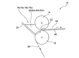
- FIG. 4 is a side cross-sectional view for explaining a method of applying a resin composition solution according to the first embodiment
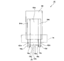
- FIG. 2 is a plan view of FIG. 1
- 3 is a partially enlarged plan view of the vicinity of a side plate 18b shown in FIG. 2
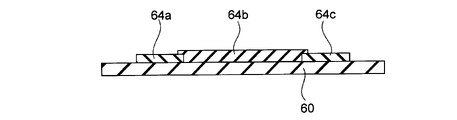
- FIG. FIG. 4 is a cross-sectional view showing a case where each coating film is connected only at the side surfaces
- FIG. 6 is a cross-sectional view showing a case where coating films 64a and 64c slightly overlap on a coating film 64b
- FIG. 11 is a cross-sectional view showing a case where a coating film 64b slightly overlaps a coating film 64a and a coating film 64c
- FIG. 10 is a side cross-sectional view for explaining a method of applying a resin composition solution according to the second embodiment;
- FIG. 8 is a plan view of FIG. 7;
- FIG. 11 is a side cross-sectional view for explaining a method of applying a resin composition solution according to the third embodiment;
- FIG. 10 is a plan view of FIG. 9;
- FIG. 11 is a cross-sectional view showing a case where the edge of the coating film 64a slightly overlaps the coating film 64b and the edge of the coating film 64b slightly overlaps the coating film 64c.
- FIG. 11 is a side cross-sectional view for explaining a method of applying a resin composition solution according to a fourth embodiment;
- FIG. 13 is a plan view of FIG. 12;
- the method for producing a resin film includes: A step of applying the first resin composition solution to the central portion of the support; step B of applying a second resin composition solution to both ends adjacent to the central portion; step C of drying the first resin composition solution and the second resin composition solution to obtain a pre-cut film; A step D of peeling the film before cutting from the support, a step E of gripping both ends of the film before cutting with a tenter-type conveying device after the step D, a step F of conveying the film before cutting while gripping both ends of the film before cutting; After the step F, the step G of obtaining a resin film by removing the portion formed from the second resin composition solution from the pre-cut film has
- the first resin composition solution contains a first resin and a filler, and the content of the filler is 0.1% by mass or more and 50% by mass or less with respect to the first resin
- the second resin composition solution contains a second resin, does not contain a filler, or even if it contains a filler
- Step A In the method for producing a resin film according to the present embodiment, first, the first resin composition solution is applied to the central portion of the support (step A). Also, a second resin composition solution is applied to both ends adjacent to the central portion (step B). The process A and the process B may be performed at the same time, the process B may be performed after the process A is performed, or the process A may be performed after the process B is performed.
- the support is not particularly limited, but preferably has resistance to the solvent of the first resin composition solution and the second resin composition solution.
- polyimide polyimide
- PAI polyamide imide
- a resin-made polymer film a metal drum, an endless steel belt, and the like.
- polymer films are preferred.
- the coating method of the step A and the step B is not particularly limited, and examples thereof include a comma coating method, a T-die coating method, a spin coating method, a spray coating method, a bar coating method, a knife coating method, a dipping method, and the like. be done. Two of these methods may be combined. A comma coating method, a T-die coating method, or a combination thereof is preferable from the viewpoint of productivity.
- process A and process B are described below.
- FIG. 1 is a side cross-sectional view for explaining the coating method of the resin composition solution according to the first embodiment
- FIG. 2 is a plan view thereof.
- the coating device 10 has a backup roll 12, a comma roll 14, and three coating liquid reservoirs 16 (16a, 16b, 16c).
- the coating liquid reservoir 16 (16a, 16b, 16c) has four side plates 18 (18a, 18b, 18c, 18d) for partitioning the coating liquid reservoir 16 and a back plate 20.
- the coating liquid reservoir 16 ( 16 a , 16 b , 16 c ) can store the coating liquid 62 in a region surrounded by the back plate 20 and the side plate 18 .
- the second resin composition solutions 62a and 62c are stored in the coating liquid reservoirs 16a and 16c located on both end sides, and the second resin composition solutions 62a and 62c are stored in the coating liquid reservoirs 16a and 16c.
- a first resin composition solution 62b is stored in the coating liquid storage portion 16b.
- the backup roll 12 continuously conveys the support 60 by rotating.
- the support 60 conveyed by the backup roll 12 passes through the gap 22 formed between the backup roll 12 and the comma roll 14 .
- the coating liquid 62 (second resin composition solutions 62a and 62c, first resin composition solution 62b) is supplied from the coating liquid reservoir 16 onto the support 60, Coating films 64 (64a, 64b, 64c) are formed. Specifically, a coating film 64 having a thickness equivalent to the thickness of the support 60 subtracted from the gap 22 is formed.
- the thickness of the coating film 64 can be controlled by the gap 22 between the backup roll 12 and the comma roll 14 or the like.
- FIG. 3 is a partially enlarged plan view of the vicinity of the side plate 18b shown in FIG.
- Each coating liquid 62 (second resin composition solutions 62a, 62c, first resin composition solution 62b) spreads in the width direction after being applied onto the support 60.
- the second resin composition solution 62a applied near the side plate 18b spreads inward in the width direction (to the right in FIGS. 2 and 3).
- the first resin composition solution 62b applied near the side plate 18b spreads outward in the width direction (to the left in FIGS. 2 and 3).
- the second resin composition solution 62a (coating film 64a) and the first resin composition solution 62b (coating film 64b) are formed at a portion where the side plate 18b in the flow direction (the upper side in FIGS. 2 and 3) is removed. is connected.
- the first resin composition solution 62b applied near the side plate 18c spreads outward in the width direction (right side in FIG. 2).
- the second resin composition solution 62c applied near the side plate 18c spreads inward in the width direction (left side in FIG. 2).
- the first resin composition solution 62b (coating film 64b) and the second resin composition solution 62c (coating film 64c) are connected where the side plate 18c in the flow direction is removed.
- the coating film 64a and the coating film 64b are connected, and the coating film 64b and the coating film 64c are connected.
- Examples of the connection include a case where the resin composition solutions forming the coating films 64 are mutually dissolved, and a case where the coating films 64 are connected by an adhesive force at the interface.
- the manner in which the coating films 64 are connected is not particularly limited, but when the coating films are connected only at the side surfaces (see FIG. 4), when one of the coating films slightly overlaps the other coating film (see FIG. 4). 5 and 6).
- FIG. 4 is a cross-sectional view showing a case where the coating films are connected only at the side surfaces.
- the coating film 64a and the coating film 64b are connected only at the side surfaces.
- the coating film 64b and the coating film 64c are connected only at the side surfaces.
- a composition gradient region is formed by mixing the first resin composition solution 62b (coating film 64b) and the second resin composition solution 62c (coating film 64c).
- the width of the composition gradient region is preferably in the range of 10 to 2500 times the thickness of the coating film 64b in the portion not in the composition gradient region. More preferably 100 to 1,000 times, still more preferably 250 to 500 times. For example, when the thickness of the coating film 64b is 20 ⁇ m, the width of the composition gradient region is preferably 0.2 mm (10 times the thickness of the coating film 64b) to 5 cm (2500 times the thickness of the coating film 64b). . Within this range, breakage from the compositionally graded region is less likely to occur during manufacturing.
- FIG. 5 is a cross-sectional view showing a case where the coating films 64a and 64c slightly overlap the coating film 64b.
- the edge of the coating film 64a slightly overlaps the coating film 64b.
- the edge of the coating film 64c slightly overlaps the coating film 64b.
- the overlapping portion is the second resin composition solution 62a (coating film 64a) and the first resin composition solution 62b (coating film 64b), or the first resin composition solution 62b (coating film 64b) and the second resin.
- a composition gradient region is formed by mixing the composition solution 62c (coating film 64c).
- the width of the composition gradient region is preferably in the range of 10 to 2500 times the thickness of the coating film 64b in the portion not in the composition gradient region.
- the width of the composition gradient region is preferably 0.2 mm (10 times the thickness of the coating film 64b) to 5 cm (2500 times the thickness of the coating film 64b). . Within this range, breakage from the compositionally graded region is less likely to occur during manufacturing.
- FIG. 6 is a cross-sectional view showing a case where the coating film 64b slightly overlaps the coating films 64a and 64c.
- the edge of the coating film 64b (the left edge in FIG. 6) slightly overlaps the coating film 64a.
- the edge of the coating film 64b (the right edge in FIG. 6) slightly overlaps the coating film 64c.
- the width of the overlapping portion as in the case of FIG. 5, it is preferable that the width is in the range of 10 to 2500 times that of the coating film 64b in the portion that is not in the compositionally graded region. More preferably 100 to 1,000 times, still more preferably 250 to 500 times. Within this range, breakage from the compositionally graded region is less likely to occur during manufacturing.
- the connection mode can be determined by the gap 22, for example. If the gap 22 through which the second resin composition solutions 62a and 62c pass is the same as the gap 22 through which the first resin composition solution 62b passes, the connection mode shown in FIG. 4 is likely to be achieved. If the gap 22 through which the second resin composition solutions 62a and 62c pass is made slightly wider than the gap 22 through which the first resin composition solution 62b passes, the connection mode shown in FIG. 5 is likely to be obtained. If the gap 22 through which the first resin composition solution 62b passes is slightly wider than the gap 22 through which the second resin composition solutions 62a and 62c pass, the connection mode shown in FIG. 6 is likely to be obtained. The connection mode can be controlled not only by the gap 22 but also by the viscosity of the first resin composition solution 62b and the second resin composition solutions 62a and 62c and the width of the side plate 18.
- process A and process B are performed simultaneously by the coating device 10 described above.
- FIG. 7 is a side sectional view for explaining the coating method of the resin composition solution according to the second embodiment
- FIG. 8 is its plan view.
- symbol is attached
- the coating device 30 has a backup roll 12, a comma roll 14, and two coating liquid reservoirs 16 (16a, 16c) on both sides in the width direction.
- the coating liquid reservoir 16 16 a, 16 c ) can store the coating liquid 62 in a region surrounded by the back plate 20 and the side plate 18 .
- Second resin composition solutions 62a and 62c are stored in the two coating liquid reservoirs 16 (16a and 16c). Note that, unlike the first embodiment, the first resin composition solution is not stored in the coating liquid reservoir 16 in the coating device 30 according to the second embodiment.
- the backup roll 12 continuously conveys the support 60 by rotating.
- the support 60 conveyed by the backup roll 12 passes through the gap 22 formed between the backup roll 12 and the comma roll 14 .
- the second resin composition solutions 62a and 62c are supplied from the coating liquid reservoir 16 onto the support 60 to form coating films 64a and 64c.
- the coating device 30 further includes a T-die coater 32.
- the T-die coater 32 is installed after the backup grow roll 12 and the comma roll 14 .
- the T-die coater 32 is installed such that the ejection port is positioned above the central portion of the support 60 .
- the T-die coater 32 applies the first resin composition solution 62b to the central portion of the support 60.
- the coating device 30 described above first performs the step B, and then performs the step A.
- the connection mode of each coating film 64 is likely to be the connection mode shown in FIG. 6, but is not limited to this.
- the first resin composition solution is first applied to the central portion of the support using a comma coater, and then the second resin composition solution is applied to both ends using a T-die coater. It may be applied.
- FIG. 9 is a side cross-sectional view for explaining the coating method of the resin composition solution according to the third embodiment
- FIG. 10 is its plan view.
- the same reference numerals are given to the configurations common to the coating device 30 of the second embodiment, and the description thereof is omitted or simplified.
- the coating device 40 includes a T-die coater 42a, a T-die coater 42b, and a T-die coater 42c.
- the T-die coater 42a and the T-die coater 42c are installed before the T-die coater 42b.
- the T-die coater 42a and the T-die coater 42c are installed such that the ejection port is located above the end of the support 60, respectively.
- the T-die coater 42 a is installed so that the discharge port is positioned above the left end of the support 60
- the T-die coater 42 c is installed so that the discharge port is positioned above the right end of the support 60 .
- is installed in The T-die coater 42b is installed so that the ejection port is positioned above the central portion of the support 60. As shown in FIG.
- the T-die coater 42b applies the first resin composition solution 62b to the central portion of the support 60.
- the bonding mode of each coating film 64 is likely to be the bonding mode shown in FIG. 5, but is not limited to this.
- the second resin composition may be applied to both ends with a T-die coater, and then the first resin composition may be applied to the central portion with a T-die coater.
- the bonding mode of each coating film 64 is likely to be the bonding mode shown in FIG. 6, but is not limited to this.
- the second resin composition is applied to the end of one side with a T-die coater, and then the first resin composition is applied to the center with a T-die coater, followed by the other side.
- each coating film 64 is likely to be the bonding mode shown in FIG. 11, but is not limited to this.
- the edge of the coating film 64a slightly overlaps the coating film 64b.
- the edge of the coating film 64b slightly overlaps the coating film 64c.
- a plurality of T-die coaters are arranged in tandem to separate the first resin composition and the second resin composition. It may be in the form of sequential application.
- FIG. 12 is a side sectional view for explaining the coating method of the resin composition solution according to the fourth embodiment
- FIG. 13 is its plan view.
- the same reference numerals are given to the configurations common to the coating device 40 of the third embodiment, and the description thereof will be omitted or simplified.
- the coating device 50 includes a T-die coater 52 having three ejection openings divided in the width direction.
- the T-die coater 52 applies the first resin composition to the central portion of the support 60 and simultaneously applies the second resin composition to both ends.
- Step A and Step B in the fourth embodiment are forms in which the first resin composition and the second resin composition are applied simultaneously.
- the bonding mode of each coating film 64 is likely to be the bonding mode shown in FIG. 4, but is not limited to this.
- step C After the step A and the step B, the first resin composition solution and the second resin composition solution are dried to obtain a film before cutting (step C).
- the drying conditions can be appropriately set within a range in which the solvent can be sufficiently volatilized.
- the drying temperature is in the range of 60° C. to 140° C.
- the drying time is in the range of 1 minute to 60 minutes. can be done.
- the drying conditions are particularly suitable when dimethylacetamide is used as a solvent because its boiling point is 165°C.
- step C-1 a step of winding the uncut film together with the support into a roll (step C-1) may be performed. In this case, before step D, the film before cutting may be unwound again.
- the film before cutting is peeled off from the support (step D).
- the method of peeling the film before cutting from the support is not particularly limited, but a method of rolling it up from the edge with tweezers or the like, making a cut in the film before cutting, and attaching an adhesive tape to one side of the cut portion.
- a method of winding from the tape portion, a method of vacuum-sucking one side of the notched portion of the film before cutting and then winding from that portion, and the like can be employed.
- As a method of rolling it is desirable to roll while winding on a roll.
- Examples of the method of cutting the film before cutting include a method of cutting the film before cutting with a cutting tool such as a knife, a method of cutting the film before cutting with a laser, and a method of cutting the film before cutting with a water jet.
- a cutting tool such as a knife
- a method of cutting the film before cutting with a laser and a method of cutting the film before cutting with a water jet.
- a step of winding the pre-cut film into a roll may be performed. In this case, before step E, the film before cutting may be unwound again.
- the period of holding in the rolled state is preferably 30 minutes or longer, more preferably 3 hours or longer.
- the solvent can be preferably diffused in the thickness direction.
- the pre-cut film is wound once in the middle of the step, so that the production apparatus can be made compact.
- the production line becomes considerably long, which may limit the location of the factory.
- the manufacturing line can be divided into two, and the two divided lines can be arranged in parallel, so that a relatively compact manufacturing apparatus can be obtained. Furthermore, by winding once during manufacturing, it is possible to check the quality during the process.
- both ends of the film before cutting are gripped by a tenter-type conveying device (step E).
- a tenter-type conveying device As the tenter-type conveying device, conventionally known ones (for example, tenter-type conveying devices disclosed in Japanese Patent No. 4843996 and Japanese Patent No. 4821960) can be used.
- the film before cutting is conveyed while holding both ends of the film before cutting (step F). You may heat in the case of conveyance.
- the heating temperature is not particularly limited, but when the first resin composition solution and the second resin composition solution are polyimide resin composition solutions, for example, 150 ° C. to 500 ° C., 1 minute to 60 minutes can be within the range.
- the film before cutting may or may not be stretched in the width direction.
- the pre-cut film In the process F, the pre-cut film generally shrinks in the width direction during transportation. Therefore, tensile tension is applied to the portion gripped by the tenter-type conveying device.
- the tear strength of both ends (portions formed from the second resin composition solution) of the film before cutting is lower than that of the central portion (portions formed from the second resin composition solution) part) tear strength. Therefore, tearing of the pre-cut film at the gripped portions (both ends) is suppressed.
- a pin tenter-type conveying device is used as the tenter-type conveying device, tearing due to the pins of the pin tenter-type conveying device is more preferably suppressed.
- step G the portion formed from the second resin composition solution is removed from the pre-cut film to obtain a resin film (step G).
- step G at least the portion formed from the second resin composition solution may be removed, and together with the portion formed from the second resin composition solution, the portion formed from the first resin composition solution may be removed. Some parts may also be removed.
- the resin film thus obtained is only the portion formed from the first resin composition solution. That is, a resin film consisting only of a portion with relatively low tear strength is obtained.
- the CTE (coefficient of linear thermal expansion) of the resin film is 5 ppm/K or more and 50 ppm/K or less. It is preferably 45 ppm/K or less, more preferably 40 ppm/K or less, and even more preferably 35 ppm/K or less, because heat resistance is improved. Industrially, it may be 6 ppm/K or more, and may be 7 ppm/K or more.
- the thickness of the resin film is not particularly limited, it is preferably 5 ⁇ m to 125 ⁇ m, more preferably 7.5 ⁇ m to 75 ⁇ m, even more preferably 12.5 ⁇ m to 50 ⁇ m.
- the method for removing the portion formed from the second resin composition solution from the film before cutting is not particularly limited, and a conventionally known slitter or the like can be used.
- the first resin composition solution and the second resin composition solution will be described below.
- the first resin composition solution and the second resin composition solution are added from the second resin composition solution in the pre-cutting film after the step C and before the step F.
- the tear strength of the formed portion is greater than the tear strength of the portion formed from the first resin composition solution, and the CTE of the resin film is 5 ppm/K or more and 50 ppm/K or less. If there is, it is not particularly limited.
- the first resin composition solution contains a first resin and a filler, and the content of the filler is 0.1% by mass or more and 50% by mass or less with respect to the first resin.
- the first resin is not particularly limited as long as it is a resin capable of solution film formation, and it may be not only a resin but also a precursor of the resin. In particular, from the viewpoint of industrial rights, it is preferably applied to resins that are difficult to form into a film by melting. Specific examples include cellulose triacetate, aromatic polyamide, polyimide, polyetherimide, polyamideimide, polyesterimide, polybenzoxazole, polybenzimidazole, and polybenzothiazole. Moreover, a polyamic acid is mentioned as a precursor of a polyimide. Among these, polyimide-based resins such as polyimide, polyamideimide, polyetherimide, and polyimidebenzoxazole are particularly preferably applicable.
- the filler content of the first resin composition solution is 0.1% by mass or more with respect to the first resin. Since the CTE of the resin film can be lowered, the content is preferably 0.2% by mass or more, more preferably 0.3% by mass or more. Further, the filler content of the first resin composition solution is 50% by mass or less with respect to the first resin. It is preferably 40% by mass or less, more preferably 30% by mass or less, still more preferably 20% by mass or less, and particularly preferably 15% by mass or less, because the resin film has good mechanical properties. .
- the first resin composition solution preferably contains a predetermined amount of the first resin and a filler, and specifically includes a cellulose triacetate resin composition solution, a polyetherimide resin composition solution, Polyesterimide resin composition solution, polybenzoxazole resin composition solution, polybenzimidazole resin composition solution, polybenzothiazole resin composition solution, polyimide resin composition solution, aromatic polyamide resin composition solution, polyamideimide system A resin composition solution and the like are included. Among them, a polyimide resin composition solution is preferable. Among polyimide resin films, those generally called transparent polyimide often have weak tear strength, but according to the method for producing a resin film according to the present embodiment, a transparent polyimide resin film with weak tear strength Even if it is, it can be manufactured suitably.
- the concentration of the first resin in the first composition solution is preferably 1% by mass or more, more preferably 5% by mass or more, from the viewpoints of operability (coatability) and economy, More preferably, it is 10% by mass or more. Also, it is preferably 80% by mass or less, more preferably 60% by mass or less, and even more preferably 40% by mass or less.
- the first polyimide resin composition solution may be a polyamic acid (polyimide precursor) solution or a polyimide solution.
- a polyamic acid solution heat treatment is performed in step F to cause a dehydration ring-closing reaction to form a polyimide film.
- the solvent is volatilized in step C to form a polyimide film.
- the heat treatment conditions can be appropriately set within a range in which the polyamic acid can be reacted with the polyimide.
- An example of the heat treatment temperature is in the range of 250 to 500.degree. C., preferably in the range of 300 to 400.degree.
- the heat treatment time can be appropriately set depending on the heat treatment temperature. For example, it can be in the range of 5 to 60 minutes, preferably in the range of 10 to 30 minutes.
- the polyamic acid solution is obtained by reacting diamines and tetracarboxylic acids in a solvent.
- tetracarboxylic acids examples include aromatic tetracarboxylic acids (including their acid anhydrides), aliphatic tetracarboxylic acids (including their acid anhydrides), alicyclic tetracarboxylic acids (including their acid anhydrides), which are commonly used in polyimide synthesis. anhydrides) can be used. Among them, aromatic tetracarboxylic anhydrides and alicyclic tetracarboxylic anhydrides are preferable, aromatic tetracarboxylic anhydrides are more preferable from the viewpoint of heat resistance, and alicyclic anhydrides are preferable from the viewpoint of light transmittance. Formula tetracarboxylic acids are more preferred.
- anhydride structures may be present in the molecule, but preferably those having two anhydride structures (dianhydrides) are good.
- Tetracarboxylic acids may be used alone, or two or more of them may be used in combination.
- solutions from which highly colorless and transparent polyimides can be obtained are preferable.
- Aromatic tetracarboxylic acids for obtaining highly colorless and transparent polyimide include 4,4′-(2,2-hexafluoroisopropylidene)diphthalic acid, 4,4′-oxydiphthalic acid, and 3,4′-oxydiphthalic acid.
- Aromatic tetracarboxylic acids may be used alone, or two or more of them may be used in combination.
- the aromatic tetracarboxylic acid is, for example, preferably 50% by mass or more, more preferably 60% by mass or more, still more preferably 70% by mass or more, and still more preferably It is 80% by mass or more.
- Alicyclic tetracarboxylic acids include 1,2,3,4-cyclobutanetetracarboxylic acid, 1,2,3,4-cyclopentanetetracarboxylic acid, 1,2,3,4-cyclohexanetetracarboxylic acid, 1 , 2,4,5-cyclohexanetetracarboxylic acid, 3,3′,4,4′-bicyclohexyltetracarboxylic acid, bicyclo[2,2,1]heptane-2,3,5,6-tetracarboxylic acid, Bicyclo[2,2,2]octane-2,3,5,6-tetracarboxylic acid, bicyclo[2,2,2]oct-7-ene-2,3,5,6-tetracarboxylic acid, tetrahydroanthracene -2,3,6,7-tetracarboxylic acid, tetradecahydro-1,4:5,8:9,10-trimethanoanthracene-2,3,
- dianhydrides having two acid anhydride structures are preferred, particularly 1,2,3,4-cyclobutanetetracarboxylic dianhydride, 1,2,3,4-cyclohexanetetracarboxylic acid Acid dianhydride, 1,2,4,5-cyclohexanetetracarboxylic dianhydride is preferred, 1,2,3,4-cyclobutanetetracarboxylic dianhydride, 1,2,4,5-cyclohexanetetracarboxylic An acid dianhydride is more preferred, and 1,2,3,4-cyclobutanetetracarboxylic acid dianhydride is even more preferred. In addition, these may be used independently and may use 2 or more types together.
- the alicyclic tetracarboxylic acid is preferably 50% by mass or more, more preferably 60% by mass or more, still more preferably 70% by mass or more, and even more preferably 70% by mass or more of the total tetracarboxylic acids. is 80% by mass or more.
- the polyamic acid solution may contain tricarboxylic acids and dicarboxylic acids.
- Tricarboxylic acids include aromatic tricarboxylic acids such as trimellitic acid, 1,2,5-naphthalenetricarboxylic acid, diphenylether-3,3′,4′-tricarboxylic acid, and diphenylsulfone-3,3′,4′-tricarboxylic acid.
- acids or hydrogenated products of the above aromatic tricarboxylic acids such as hexahydrotrimellitic acid; Glycol bistrimellitate, and their monoanhydrides and esters.
- monoanhydrides having one acid anhydride structure are preferred, and trimellitic anhydride and hexahydrotrimellitic anhydride are particularly preferred. In addition, these may be used individually and may be used in combination.
- Dicarboxylic acids include aromatic dicarboxylic acids such as terephthalic acid, isophthalic acid, orthophthalic acid, naphthalenedicarboxylic acid, 4,4'-oxydibenzenecarboxylic acid, or the above aromatic dicarboxylic acids such as 1,6-cyclohexanedicarboxylic acid.
- aromatic dicarboxylic acids and hydrogenated products thereof are preferred, and terephthalic acid, 1,6-cyclohexanedicarboxylic acid, and 4,4'-oxydibenzenecarboxylic acid are particularly preferred.
- dicarboxylic acids may be used alone or in combination.
- Diamines or isocyanates for obtaining highly colorless and transparent polyimides are not particularly limited, and polyimide synthesis, polyamideimide synthesis, aromatic diamines, aliphatic diamines, and alicyclic diamines commonly used in polyamide synthesis. , aromatic diisocyanates, aliphatic diisocyanates, alicyclic diisocyanates, and the like can be used. From the viewpoint of heat resistance, aromatic diamines are preferred, and from the viewpoint of transparency, alicyclic diamines are preferred. In addition, the use of aromatic diamines having a benzoxazole structure makes it possible to exhibit high heat resistance, high elastic modulus, low thermal shrinkage, and low coefficient of linear expansion. Diamines and isocyanates may be used alone or in combination of two or more.
- aromatic diamines examples include 2,2′-dimethyl-4,4′-diaminobiphenyl, 1,4-bis[2-(4-aminophenyl)-2-propyl]benzene, 1,4-bis (4-amino-2-trifluoromethylphenoxy)benzene, 2,2′-bis(trifluoromethyl)-4,4′-diaminobiphenyl, 4,4′-bis(4-aminophenoxy)biphenyl, 4, 4′-bis(3-aminophenoxy)biphenyl, bis[4-(3-aminophenoxy)phenyl]ketone, bis[4-(3-aminophenoxy)phenyl]sulfide, bis[4-(3-aminophenoxy) phenyl]sulfone, 2,2-bis[4-(3-aminophenoxy)phenyl]propane, 2,2-bis[4-(3-aminophenoxy)phenyl]-1,1,1,3,
- aromatic diamines having a benzoxazole structure are not particularly limited, and examples thereof include 5-amino-2-(p-aminophenyl)benzoxazole, 6-amino-2-(p-aminophenyl)benzoxazole, oxazole, 5-amino-2-(m-aminophenyl)benzoxazole, 6-amino-2-(m-aminophenyl)benzoxazole, 2,2′-p-phenylenebis(5-aminobenzoxazole), 2 , 2′-p-phenylenebis(6-aminobenzoxazole), 1-(5-aminobenzoxazolo)-4-(6-aminobenzoxazolo)benzene, 2,6-(4,4′-diamino diphenyl)benzo[1,2-d:5,4-d']bisoxazole, 2,6-(4,4'-diaminodiphenyl)benzo
- aromatic diamines may be used singly or in combination.
- Alicyclic diamines include, for example, 1,4-diaminocyclohexane, 1,4-diamino-2-methylcyclohexane, 1,4-diamino-2-ethylcyclohexane, 1,4-diamino-2-n-propyl cyclohexane, 1,4-diamino-2-isopropylcyclohexane, 1,4-diamino-2-n-butylcyclohexane, 1,4-diamino-2-isobutylcyclohexane, 1,4-diamino-2-sec-butylcyclohexane, 1,4-diamino-2-tert-butylcyclohexane, 4,4'-methylenebis(2,6-dimethylcyclohexylamine) and the like.
- 1,4-diaminocyclohexane and 1,4-diamino-2-methylcyclohexane are particularly preferred, and 1,4-diaminocyclohexane is more preferred.
- the alicyclic diamines may be used alone or in combination.
- Diisocyanates include, for example, diphenylmethane-2,4'-diisocyanate, 3,2'- or 3,3'- or 4,2'- or 4,3'- or 5,2'- or 5,3' - or 6,2'- or 6,3'-dimethyldiphenylmethane-2,4'-diisocyanate, 3,2'- or 3,3'- or 4,2'- or 4,3'- or 5,2 '- or 5,3'- or 6,2'- or 6,3'-diethyldiphenylmethane-2,4'-diisocyanate, 3,2'- or 3,3'- or 4,2'- or 4, 3'- or 5,2'- or 5,3'- or 6,2'- or 6,3'-dimethoxydiphenylmethane-2,4'-diisocyanate, diphenylmethane-4,4'-diisocyanate, diphenylmethane-3, 3'-diisocyanate,
- Diisocyanates may be used alone or in combination.
- any solvent that can dissolve the polyimide or the precursor of the polyimide can be used, and an aprotic polar solvent or the like can be suitably used.
- N,N-di-lower alkyl carboxylamides such as N,N-dimethylformamide, N,N-dimethylacetamide, N,N-diethylacetamide, N,N-dimethylmethoxyacetamide, N-methyl-2-pyrrolidone , N-ethyl-2-pyrrolidone, dimethylsulfoxide, dimethylsulfone, 1,3-dimethyl-2-imidazolidinone, ⁇ -butyrolactone, diglyme, m-cresol, hexamethylphosphoramide, N-acetyl-2-pyrrolidone , hexamethylphosphoramide, ethyl cellosolve acetate, diethylene glycol dimethyl ether, sulfolane, p-chlorophenol and
- the filler is not particularly limited, organic particles, inorganic particles and the like can be mentioned, and inorganic particles are particularly preferable.
- inorganic particles include metal oxide particles such as silica, zirconia, alumina, titania, titanium oxide, zinc oxide, germanium oxide, indium oxide, tin oxide, indium tin oxide (ITO), antimony oxide, and cerium oxide;
- metal fluoride particles such as magnesium and sodium fluoride.
- transparent or colorless fillers are preferred.
- Silica is more preferable from the viewpoint of dispersibility in resin and heat resistance.
- the shape of the filler is not particularly limited, but it may be particulate or fibrous.
- the size of the filler is not particularly limited, it is preferably 0.5 to 180 nm, more preferably 2 to 100 nm. If it is 0.5 nm or more, the low CTE effect of the resin film can be exhibited. Moreover, if it is 180 nm or less, turbidity, white turbidity, or coloration of the resin film can be suppressed.
- the filler can be used alone or in combination.
- the location of the filler present in the resin film is not particularly limited. may be any one of the filler present in the resin film.
- the second resin composition solution contains a second resin, does not contain a filler, or even if it contains a filler, the content is less than the content of the first resin composition solution, and the second resin is 2% by mass or less.
- the second resin composition solution does not contain a filler, or even if it contains a filler, it is less than the content of the first resin composition solution and is 2% by mass or less with respect to the second resin. .
- the amount of filler in the second resin is preferably 1% by mass or less, more preferably 0.5% by mass or less, and still more preferably 0.1% by mass, because tear strength at both ends is improved. or less, and particularly preferably 0% by mass.
- the second resin is not particularly limited as long as it is capable of solution casting and has a higher tear strength than the first resin when forming a film, and is the same as the first resin. It may be the same composition or different compositions. Specific examples include cellulose triacetate, aromatic polyamide, polyimide, polyetherimide, polyamideimide, polyesterimide, polybenzoxazole, polybenzimidazole, and polybenzothiazole. Moreover, a polyamic acid is mentioned as a precursor of a polyimide. Among these, polyimide-based resins such as polyimide, polyamideimide, polyetherimide, and polyimidebenzoxazole are particularly preferably applicable.
- the second resin composition solution examples include a polyimide resin composition solution, a polyamide resin composition solution, a polyamideimide resin composition solution, and the like.
- the polyimide resin composition solution is also used as the second resin composition solution from the viewpoint of close heat resistance. It is preferable to use It is preferable that the second resin composition solution has heat resistance equal to or higher than that of the first resin composition solution.
- the concentration of the second resin in the second composition solution is preferably 1% by mass or more, more preferably 5% by mass or more, from the viewpoint of operability (coatability) and economy, More preferably, it is 10% by mass or more. Also, it is preferably 80% by mass or less, more preferably 60% by mass or less, and even more preferably 40% by mass or less.
- the second polyimide resin composition solution may be a polyamic acid (polyimide precursor) solution or a polyimide solution.
- a polyamic acid solution heat treatment is performed in step F to cause a dehydration ring-closing reaction to form a polyimide film.
- a polyimide solution the solvent is volatilized in step C to form a polyimide film.
- the heat treatment conditions are the same as those for the first polyimide resin composition solution.
- the polyamic acid solution is obtained by reacting diamines and tetracarboxylic dianhydrides in a solvent.
- tetracarboxylic acids examples include aromatic tetracarboxylic acids (including their acid anhydrides), aliphatic tetracarboxylic acids (including their acid anhydrides), alicyclic tetracarboxylic acids (including their acid anhydrides), which are commonly used in polyimide synthesis. anhydrides) can be used. Among them, aromatic tetracarboxylic anhydrides and alicyclic tetracarboxylic anhydrides are preferred. Tetracarboxylic acids may be used alone or in combination of two or more.
- alicyclic tetracarboxylic acids examples include alicyclic tetracarboxylic acids such as cyclobutanetetracarboxylic acid, 1,2,4,5-cyclohexanetetracarboxylic acid, and 3,3′,4,4′-bicyclohexyltetracarboxylic acid.
- Carboxylic acids, and their acid anhydrides are preferred.
- dianhydrides having two anhydride structures for example, cyclobutanetetracarboxylic dianhydride, 1,2,4,5-cyclohexanetetracarboxylic dianhydride, 3,3′,4,4 '-bicyclohexyltetracarboxylic dianhydride are preferred.
- the alicyclic tetracarboxylic acids may be used alone, or two or more of them may be used in combination.
- the alicyclic tetracarboxylic acid is, for example, preferably 80% by mass or more, more preferably 90% by mass or more, and still more preferably 95% by mass or more of the total tetracarboxylic acids when transparency is important.
- aromatic tetracarboxylic acids include, but are not limited to, pyromellitic dianhydride, 3,3′,4,4′-biphenyltetracarboxylic dianhydride, and 4,4′-oxydiphthalic dianhydride. , 3,3′,4,4′-benzophenonetetracarboxylic dianhydride, 3,3′,4,4′-diphenylsulfonetetracarboxylic dianhydride, 2,2-bis[4-(3,4 -dicarboxyphenoxy)phenyl]propanoic anhydride and the like.
- the aromatic tetracarboxylic acid is, for example, preferably 80% by mass or more, more preferably 90% by mass or more, and still more preferably 95% by mass or more of the total tetracarboxylic acids when heat resistance is important.
- the diamines are not particularly limited, and aromatic diamines, aliphatic diamines, etc. that are commonly used in polyimide synthesis can be used. From the viewpoint of heat resistance, aromatic diamines are preferred, and among aromatic diamines, aromatic diamines having a benzoxazole structure are more preferred. The use of aromatic diamines having a benzoxazole structure makes it possible to exhibit high heat resistance, high elastic modulus, low thermal shrinkage, and low coefficient of linear expansion. Diamines may be used alone or in combination of two or more.
- Aromatic diamines having a benzoxazole structure are not particularly limited, and examples include 5-amino-2-(p-aminophenyl)benzoxazole, 6-amino-2-(p-aminophenyl)benzoxazole, 5 -amino-2-(m-aminophenyl)benzoxazole, 6-amino-2-(m-aminophenyl)benzoxazole, 2,2'-p-phenylenebis(5-aminobenzoxazole), 2,2' -p-phenylenebis(6-aminobenzoxazole), 1-(5-aminobenzoxazolo)-4-(6-aminobenzoxazolo)benzene, 2,6-(4,4'-diaminodiphenyl)benzo [1,2-d:5,4-d′]bisoxazole, 2,6-(4,4′-diaminodiphenyl)benzo[1,2-d:4,5-
- aromatic diamines other than the above aromatic diamines having a benzoxazole structure examples include 2,2′-dimethyl-4,4′-diaminobiphenyl, 1,4-bis[2-(4-aminophenyl )-2-propyl]benzene (bisaniline), 1,4-bis(4-amino-2-trifluoromethylphenoxy)benzene, 2,2′-ditrifluoromethyl-4,4′-diaminobiphenyl, 4,4 '-bis(4-aminophenoxy)biphenyl, 4,4'-bis(3-aminophenoxy)biphenyl, bis[4-(3-aminophenoxy)phenyl]ketone, bis[4-(3-aminophenoxy)phenyl ] sulfide, bis[4-(3-aminophenoxy)phenyl]sulfone, 2,2-bis[4-(3-aminophenoxy)phenyl]propane,
- aliphatic diamines examples include 1,2-diaminoethane, 1,4-diaminobutane, 1,5-diaminopentane, 1,6-diaminohexane, 1,8-diaminooctane and the like.
- examples of the aliphatic diamines include 1,4-diaminocyclohexane and 4,4'-methylenebis(2,6-dimethylcyclohexylamine).
- the total amount of diamines other than aromatic diamines (aliphatic diamines) is preferably 20% by mass or less, more preferably 10% by mass or less, and even more preferably 5% by mass or less, based on all diamines. In other words, aromatic diamines are preferably 80% by mass or more, more preferably 90% by mass or more, and still more preferably 95% by mass or more of all diamines.
- the same one as described in the section of the first resin composition solution can be used.
- the film before cutting according to this embodiment is a central part; Having both ends formed continuously from the central part at both ends of the central part,
- the central portion is composed of a first resin composition containing a first resin and a filler, and the content of the filler is 0.1% by mass or more and 50% by mass with respect to the first resin. % or less
- the both ends are composed of a second resin composition containing a second resin, and the second resin composition does not contain a filler, or even if it contains a filler, it is the same as the first resin composition. less than the content of the substance and 2% by mass or less with respect to the second resin,
- the tear strength of the both end portions is greater than the tear strength of the central portion.
- the pre-cut film can be obtained through the steps A to C of the resin film manufacturing method according to the present embodiment.
- the "first resin composition” refers to the composition (sheet material) after drying the first resin composition solution in the step C
- the “second resin composition” It refers to the composition (sheet-like material) after drying the second resin composition solution in the step C above.
- the CTE of the central portion of the film before cutting is preferably 5 ppm/K or more and 50 ppm/K or less. It is preferably 45 ppm/K or less, more preferably 40 ppm/K or less, and still more preferably 35 ppm/K or less, because the heat resistance of the resin film is improved. Industrially, it may be 6 ppm/K or more, and may be 7 ppm/K or more.
- the total light transmittance of the central portion of the film before cutting is preferably 80% or more, more preferably 85% or more, and still more preferably 88% or more. Although the upper limit of the total light transmittance is not particularly limited, industrially it may be 99% or less, or 98% or less.
- the haze rate of the central portion of the film before cutting is preferably 5% or less, more preferably 3% or less, and still more preferably 1% or less.
- the lower limit of the haze ratio is not particularly limited, it may be industrially 0.01% or more, or 0.1% or more.
- the YI (yellowness index) of the central portion of the film before cutting is preferably 10 or less, more preferably 7 or less, and still more preferably 5 or less.
- the lower limit of YI (yellowness index) is not particularly limited, it may be 1 or more industrially.
- the static friction coefficient of the central portion of the film before cutting is preferably 2.5 or less, more preferably 2 or less, and still more preferably 1.5 or less.
- the lower limit of the coefficient of static friction is not particularly limited, but industrially it may be 0.01 or more, and may be 0.1 or more.
- the tear strength of the central portion is preferably within the range of 0.1 to 15 N/mm, more preferably within the range of 1 to 10 N/mm, as measured by the following measuring method.
- the tear strength at both ends is preferably in the range of 0.5 to 30 N/mm, more preferably in the range of 1 to 20 N/mm, as measured by the following measuring method. Moreover, the tear strength of the both ends is preferably more than 1 times and 10 times or less, more preferably more than 1.1 times and 5 times or less of the tear strength of the central portion.
- the width of the both ends is not particularly limited as long as it is a width that can be gripped by a conventionally known tenter-type conveying device, and is generally 5 mm or more, preferably 10 mm. That's it.
- the upper limit of the width is not particularly limited, and for example, the total width of both ends may be 50% or less, more preferably 30% or less, and still more preferably 10% or less of the total width of the film.
- the width of the both ends (the width of each end) is not particularly limited as long as it is a width that can be gripped by a conventionally known tenter-type conveying device. It is 0.1% or more, more preferably 0.5% or more, and still more preferably 1% or more.
- the upper limit of the width is not particularly limited, and for example, the sum of the widths at both ends may be 50% or less, more preferably 30% or less, and still more preferably 10% or less of the total width of the film.
- the pre-cut film according to this embodiment has been described above.
- the obtained imidizing agent and 1000 parts by mass of the polyimide solution containing the imidization accelerator are transferred to a reaction vessel equipped with a stirring device and a stirring blade, and stirred at a speed of 120 rpm at 15 to 25 ° C. and 1500 parts by mass of methanol was dropped at a rate of 10 g/min.
- a reaction vessel equipped with a stirring device and a stirring blade, and stirred at a speed of 120 rpm at 15 to 25 ° C. and 1500 parts by mass of methanol was dropped at a rate of 10 g/min.
- turbidity of the polyimide solution was confirmed, and precipitation of powdery polyimide was confirmed.
- 1500 parts by mass of methanol was added to complete the deposition of polyimide.
- the contents of the reaction vessel were filtered using a suction filtration device, and washed and filtered using 1000 parts by mass of methanol.
- polyimide powder 50 parts by mass of the filtered polyimide powder was dried at 50° C. for 24 hours using a dryer equipped with a local exhaust device, and further dried at 260° C. for 2 hours to remove the remaining volatile components. , to obtain a polyimide powder.
- the resulting polyimide powder had a reduced viscosity of 2.1 dl/g.
- 42 parts by mass of the obtained polyimide powder was dissolved in 168 parts by mass of DMAC to obtain a polyimide solution B with a solid content of 20% by mass.
- Example 1 A polyamic acid solution A (Synthesis Example 1 (PAA-A)) was prepared. Among them, Snowtex (registered trademark) DMAc-ST (DMAc dispersion of silica with an average particle size of 10 nm. Active ingredient 20% by mass: Nissan Chemical Industries) is added to the resin so that the active ingredient is 10% by mass. Polyamic acid solution A was added while stirring. After that, stirring was maintained for 6 hours to obtain polyamic acid solution A-1 (PAA-A1). Using the comma coater shown in FIGS.
- the clearance was adjusted so that the final film thickness of the polyamic acid solution A-1 was 22 ⁇ m on the central part of the PET film (A4100 manufactured by Toyobo Co., Ltd.) with a width of 500 mm.
- polyamic acid solution A was applied to each of both ends with a width of 50 mm.
- the width of the side plate used was 10 mm. Then, it was dried at 100 to 110° C. for 10 minutes to form a polyamic acid film, and after drying, it was wound around a 6-inch ABS core together with the PET film to obtain a polyamic acid film roll.
- a polyamic acid film and a PET film were unwound from the obtained polyamic acid film roll, and the self-supporting polyamic acid film was peeled off from the PET film to obtain a polyamic acid film.
- the obtained polyamic acid film is passed through a pin tenter having pin sheets arranged so that the pin intervals are constant when the pin sheets are lined up, and the edge of the film is gripped by inserting the pins, and the film is broken. Adjust the distance between the pin sheets so as not to cause unnecessary sagging, and convey so that the final distance between the pin sheets is 520 mm. Heating was performed for 3 minutes, 300° C. for 3 minutes as the third stage, and 350° C. for 3 minutes as the fourth stage to advance the imidization reaction.
- the film was cooled to room temperature for 2 minutes, and then the edges of the film formed by the polyamic acid solution A were slit to leave only the central portion to obtain a polyimide film having a thickness of 22 ⁇ m and a width of 480 mm.
- Example 2 A polyamic acid solution A (Synthesis Example 1) was prepared. Among them, Snowtex (registered trademark) DMAc-ST (DMAc dispersion of silica with an average particle size of 10 nm. Active ingredient 20% by mass: Nissan Chemical Industries) is added to the resin so that the active ingredient is 5% by mass. Polyamic acid solution A was added while stirring. After that, stirring was maintained for 6 hours to obtain polyamic acid solution A-2 (PAA-A2). Subsequently, Snowtex (registered trademark) DMAc-ST-ZL (DMAc dispersion of silica with an average particle size of 80 nm.
- Snowtex (registered trademark) DMAc-ST-ZL DMAc dispersion of silica with an average particle size of 80 nm.
- Example 3 A polyamic acid solution A (Synthesis Example 1) was prepared. Among these, Snowtex (registered trademark) DMAc-ST (DMAc dispersion of silica with an average particle size of 10 nm. Active ingredient 20% by mass: Nissan Chemical Industries) and Snowtex (registered trademark) DMAc-ST-ZL (average particle size) DMAc dispersion of silica with a diameter of 80 nm. Active ingredient: 20% by mass: Nissan Chemical Industries). Polyamic acid solution A is further stirred so that the active ingredient is 0.3% by mass and 0.2% by mass, respectively, relative to the resin. I put it in while Stirring was then maintained for 6 hours to obtain polyamic acid solution A-4 (PAA-A4).
- PAA-A4 polyamic acid solution A-4
- a polyimide film having a thickness of 35 ⁇ m and a width of 480 mm was carried out in the same manner as in Example 1 except that instead of the polyamic acid solution A-1, the polyamic acid solution A-4 was applied with the clearance adjusted so that the final film thickness was 35 ⁇ m. got
- Example 4 A polyimide solution B (Synthesis Example 2 (PI-B)) was prepared. Among these, Snowtex (registered trademark) DMAc-ST (DMAc dispersion of silica with an average particle size of 10 nm. Active ingredient 20% by mass: Nissan Chemical Industries) is used as a part, and the active ingredient is 10% by mass with respect to the resin. , the polyimide solution B was added while stirring. After that, stirring was maintained for 6 hours to obtain polyimide solution B-1 (PI-B1).
- Snowtex registered trademark
- DMAc-ST DMAc dispersion of silica with an average particle size of 10 nm.
- Active ingredient 20% by mass: Nissan Chemical Industries is used as a part, and the active ingredient is 10% by mass with respect to the resin.
- the polyimide solution B was added while stirring. After that, stirring was maintained for 6 hours to obtain polyimide solution B-1 (PI-B1).
- Example 2 The same as in Example 1 except that the polyimide solution B-1 was applied instead of the polyamic acid solution A-1, and the polyimide solution B was applied instead of the polyamic acid solution A, with the clearance adjusted so that the final film thickness was 115 ⁇ m. Thus, a polyimide film having a thickness of 115 ⁇ m and a width of 480 mm was obtained.
- Example 5 A polyimide solution C (Synthesis Example 3 (PI-C)) was prepared.
- Snowtex (registered trademark) DMAc-ST DMAc dispersion of silica with an average particle size of 10 nm.
- Active ingredient 20% by mass: Nissan Chemical Industries is used as a part, and the active ingredient is 10% by mass with respect to the resin.
- the polyimide solution B was added while stirring. After that, stirring was maintained for 6 hours to obtain polyimide solution C-1 (PI-C1).
- Polyimide solution C was applied onto both ends of the mirror-finished stainless steel belt with the comma coater shown in FIGS. The clearance was adjusted so that it was applied.
- the coating was applied so that the width of the central portion was 1000 mm and the width of both ends was 50 mm. Then, it was dried at 100 to 110° C. for 10 minutes, and peeled off from the support after drying to obtain a self-supporting polyimide film.
- the obtained pre-cut film is passed through a pin tenter having pin sheets arranged so that the pin intervals are constant when the pin sheets are lined up, and the ends of the film are gripped by inserting the pins into the pins to break the film. Adjust the distance between the pin sheets so as not to cause unnecessary sagging, and convey so that the final distance between the pin sheets is 1000 mm. Heating was performed for 3 minutes, 300° C. for 3 minutes as the third stage, and 350° C.
- the film was cooled to room temperature for 2 minutes, then the edge of the film formed by the polyimide solution B was slit to leave only the central portion, and the film was continuously wound around a 3-inch ABS resin core in a roll shape to a thickness of 25 ⁇ m. , a polyimide film having a width of 980 mm and a length of 500 m was obtained.
- Example 6 A polyimide solution A (Synthesis Example 1) and a polyamic acid solution D (Synthesis Example 4 (PAA-D)) were prepared.
- Active ingredient 20% by mass: Nissan Chemical Industries) is added to a part of this polyamic acid solution A, and the active ingredient is added to the resin.
- the polyimide solution A was added while stirring so that each of them became 0.1% by mass. After that, stirring was maintained for 6 hours to obtain polyimide solution A-5 (PAA-A5).
- Snowtex (registered trademark) DMAc-ST-ZL DMAc dispersion of silica with an average particle size of 80 nm.
- Active ingredient 20% by mass: Nissan Chemical Industries is added to a part of the polyamic acid solution D, and the active ingredient is added to the resin.
- the polyimide solution B was added with stirring so that each of the After that, stirring was maintained for 6 hours to obtain polyimide solution D-1 (PAA-D1).
- Polyimide solution A-5 is applied to both ends of the T-die shown in FIGS. 9 and 10 on a mirror-finished stainless steel belt, and polyamic acid solution D-1 is applied to the center with a T-die to a final film thickness of 26 ⁇ m. The clearance was adjusted so that it was applied.
- the coating was applied so that the width of the central portion was 1000 mm and the width of both ends was 50 mm. Then, it was dried at 100 to 110° C. for 10 minutes and peeled off from the support after drying to obtain a self-supporting polyamic acid film.
- the obtained pre-cut film is passed through a pin tenter having pin sheets arranged so that the pin intervals are constant when the pin sheets are lined up, and the ends of the film are gripped by inserting the pins into the pins to break the film. Adjust the distance between the pin sheets so as not to cause unnecessary sagging, and convey so that the final distance between the pin sheets is 520 mm. Heating was performed for 3 minutes, 300° C. for 3 minutes as the third stage, and 350° C.
- the film was cooled to room temperature for 2 minutes, then the edge of the film formed by the polyimide solution A-5 was slit to leave only the central portion, and the film was continuously wound around a 3-inch ABS resin core into a roll, A polyimide film having a thickness of 26 ⁇ m, a width of 980 mm and a length of 500 m was obtained.
- Example 7 A polyamideimide solution E (Synthesis Example 5 (PAI-E)) was prepared. Snowtex (registered trademark) DMAc-ST (DMAc dispersion of silica with an average particle size of 10 nm. Active ingredient: 20% by mass: Nissan Chemical Industries) is added to a part of this polyamideimide solution E, and the active ingredient is 10 per resin. The polyamide-imide solution E was added while stirring so that the mass % was obtained. Stirring was then maintained for 6 hours to obtain polyamideimide solution E-1 (PAI-E1).
- Snowtex registered trademark
- DMAc-ST DMAc dispersion of silica with an average particle size of 10 nm.
- Active ingredient 20% by mass: Nissan Chemical Industries
- the polyamideimide solution E was applied by adjusting the clearance so that the final film thickness was 42 ⁇ m, and the polyamideimide solution E-1 was used instead of the polyamic acid solution D-1.
- a polyimide film having a thickness of 42 ⁇ m and a width of 480 mm was obtained in the same manner as in Example 6 except for the above.
- Example 8 A polyimide solution B (synthesis example 2) and a polyamic acid solution A (synthesis example 1) were prepared.
- Snowtex (registered trademark) DMAc-ST-ZL DMAc dispersion of silica with an average particle size of 80 nm.
- Active ingredient 20% by mass: Nissan Chemical Industries is added to the polyimide solution B, and the active ingredient is 0 for the resin.
- the polyimide solution B was added while stirring so as to make 5% by mass. After that, stirring was maintained for 6 hours to obtain polyimide solution B-2 (PI-B2).
- Snowtex (registered trademark) DMAc-ST DMAc dispersion of silica with an average particle size of 10 nm.
- Active ingredient 20% by mass: Nissan Chemical Industries) is added to the polyamic acid solution A, and the active ingredient is 10% by mass with respect to the resin.
- Polyimide solution A was added with stirring so that After that, stirring was maintained for 6 hours to obtain polyimide solution A-1 (PI-A1).
- PI-A1 polyimide solution A-1
- a polyimide film having a thickness of 25 ⁇ m and a width of 480 mm was obtained in the same manner as in Example 1, except that instead of the polyamic acid solution A, the polyimide solution B-2 was applied with the clearance adjusted so that the final film thickness was 25 ⁇ m. .
- Example 9 Instead of a pin tenter having a pin sheet with pins arranged so that the pin spacing is constant when the pin sheets are lined up, a clip tenter that holds both ends with clips was used, and polyamic acid solution A was used as the final film thickness.
- a polyimide film having a thickness of 75 ⁇ m and a width of 480 mm was obtained in the same manner as in Example 1, except that the clearance was adjusted to 75 ⁇ m.
- Example 10 A polyimide solution B (synthesis example 2) and a polyamideimide solution E (synthesis example 5) were prepared. Among them, Snowtex (registered trademark) DMAc-ST (DMAc dispersion of silica with an average particle size of 10 nm. Active ingredient 20% by mass: Nissan Chemical Industries) is added to the polyamideimide solution E, and the active ingredient is 10 mass with respect to the resin. %, the polyamideimide solution E was added while stirring. Stirring was then maintained for 6 hours to obtain polyamideimide solution E-1 (PAI-E1).
- Snowtex registered trademark
- DMAc-ST DMAc dispersion of silica with an average particle size of 10 nm.
- Active ingredient 20% by mass: Nissan Chemical Industries is added to the polyamideimide solution E, and the active ingredient is 10 mass with respect to the resin. %, the polyamideimide solution E was added while stirring. Stirring was then maintained for 6 hours to obtain polyamideimide solution E-1 (PAI-E1).
- Example 1 except that the polyimide solution B was applied instead of the polyamic acid solution A, and the polyimide solution E-1 was applied instead of the polyamic acid solution A-1, with the clearance adjusted so that the final film thickness was 25 ⁇ m. Similarly, a polyamideimide film having a thickness of 25 ⁇ m and a width of 480 mm was obtained.
- Example 11 Snowtex (registered trademark) DMAc-ST (DMAc dispersion of silica with an average particle size of 10 nm. Active ingredient 20% by mass: Nissan Chemical Industries) was added so that the active ingredient was 10% by mass with respect to the resin. , In the same manner as in Example 1 except that titanium oxide (average particle size 200 nm) was added so that the active ingredient was 0.75% by mass with respect to the resin (PAA-A6), the thickness was 22 ⁇ m and the width was 480 mm. of the polyimide film was obtained.
- Nissan Chemical Industries Nissan Chemical Industries
- Example 12 A polyimide solution B (synthesis example 2) and a polyamideimide solution E (synthesis example 5) were prepared.
- Snowtex (registered trademark) DMAc-ST DMAc dispersion of silica with an average particle size of 10 nm.
- Active ingredient: 20% by mass: Nissan Chemical Industries is added to polyimide solution B, and the active ingredient is 10% by mass with respect to the resin.
- Polyimide solution B was added while stirring so that After that, stirring was maintained for 6 hours to obtain a polyimide solution B-1.
- Snowtex (registered trademark) DMAc-ST DMAc dispersion of silica with an average particle size of 10 nm.
- Active ingredient 20% by mass: Nissan Chemical Industries) is added to the polyamideimide solution E, and the active ingredient is 1% by mass with respect to the resin.
- Polyamideimide solution E was added while stirring so that Stirring was then maintained for 6 hours to obtain polyamideimide solution E-2 (PAI-E2).
- PAI-E2 polyamideimide solution E-2
- a polyamideimide film having a thickness of 25 ⁇ m and a width of 480 mm was obtained in the same manner as in Example 1.
- a polyamic acid solution A (Synthesis Example 1) was prepared. Among them, Snowtex (registered trademark) DMAc-ST (DMAc dispersion of silica with an average particle size of 10 nm. Active ingredient 20% by mass: Nissan Chemical Industries) is added to the resin so that the active ingredient is 10% by mass. Polyamic acid solution A was added while stirring. After that, stirring was maintained for 6 hours to obtain polyamic acid solution A-1. Next, in the remaining polyamic acid solution A, Snowtex (registered trademark) DMAc-ST (DMAc dispersion of silica with an average particle size of 10 nm. Active ingredient: 20% by mass: Nissan Chemical Industries) is added to the resin so that the active ingredient is 5% by mass.
- Snowtex (registered trademark) DMAc-ST DMAc dispersion of silica with an average particle size of 10 nm. Active ingredient: 20% by mass: Nissan Chemical Industries
- Polyamic acid solution A was added while stirring so that After that, stirring was maintained for 6 hours to obtain polyamic acid solution A-2.
- the clearance was adjusted so that the final film thickness of the polyamic acid solution A-1 was 22 ⁇ m on the central part of the PET film (A4100 manufactured by Toyobo Co., Ltd.) with a width of 500 mm.
- polyamic acid solution A-2 was applied to each of both ends with a width of 50 mm. At this time, the width of the side plate used was 10 mm. Then, it was dried at 100 to 110° C.
- the obtained polyamic acid film is passed through a pin tenter having pin sheets arranged so that the pin intervals are constant when the pin sheets are lined up, and the edge of the film is gripped by inserting the pins, and the film is broken. Adjust the distance between the pin sheets so as not to cause unnecessary sagging, and convey so that the final distance between the pin sheets is 520 mm.
- Heating was performed for 3 minutes, 300° C. for 3 minutes as the third stage, and 350° C. for 3 minutes as the fourth stage to advance the imidization reaction. After that, it was cooled to room temperature for 2 minutes. Attempts were made to remove the film from the pins, but the holes through which the pins were passed were broken, and the film could not be obtained.
- a polyimide solution B (Synthesis Example 2) was prepared. In the same manner as in Example 1, except that instead of polyamic acid solution A and polyamic acid solution A-1, polyimide solution B was applied with a clearance adjusted so that the final film thickness was 25 ⁇ m, a thickness of 25 ⁇ m and a width of 480 mm were applied. A polyimide film was obtained.
- a polyimide solution A (Synthesis Example 2) was prepared. Among them, Snowtex (registered trademark) DMAc-ST (DMAc dispersion of silica with an average particle size of 10 nm. Active ingredient 20% by mass: Nissan Chemical Industries) is added to the resin so that the active ingredient is 60% by mass. Polyamic acid solution A was added while stirring. Stirring was then maintained for 6 hours to obtain polyamic acid solution A-7 (PAA-A7). An attempt was made to produce a film in the same manner as in Example 1, except that instead of the polyamic acid solution A-1, the polyimide solution A-7 was applied with the clearance adjusted so that the final film thickness was 25 ⁇ m. A film could not be obtained because the holes were broken.
- Snowtex registered trademark
- DMAc-ST DMAc dispersion of silica with an average particle size of 10 nm. Active ingredient 20% by mass: Nissan Chemical Industries
- PAA-7 polyamic acid solution A-7
- a polyimide solution A (Synthesis Example 2) was prepared. Snowtex (registered trademark) DMAc-ST (DMAc dispersion of silica with an average particle size of 10 nm. Active ingredient 20% by mass: Nissan Chemical Industries) is added to this polyamic acid solution A so that the active ingredient is 10% by mass with respect to the resin. The polyamic acid solution A was put into while stirring. After that, stirring was maintained for 6 hours to obtain polyamic acid solution A-1. An attempt was made to produce a film in the same manner as in Example 1 except that instead of the polyamic acid solution A, the polyimide solution A-1 was applied with the clearance adjusted so that the final film thickness was 25 ⁇ m. A film could not be obtained because the holes were broken.
- Snowtex registered trademark
- DMAc-ST DMAc dispersion of silica with an average particle size of 10 nm.
- Active ingredient 20% by mass: Nissan Chemical Industries is added to this polyamic acid solution A so that the active ingredient is 10% by mass with respect to the resin.
- ⁇ CTE linear thermal expansion coefficient
- MD direction machine direction
- TD direction width direction
- the expansion ratio is measured under the following conditions, and at intervals of 15 ° C. such as 30 ° C. to 45 ° C. and 45 ° C. to 60 ° C.
- This measurement was performed up to 300° C., the average value of all measured values was calculated as CTE, and the average value of the measured values in the MD and TD directions was obtained.
- a Hazemeter (NDH5000, manufactured by Nippon Denshoku Co., Ltd.) was used to measure the total light transmittance of the film.
- a D65 lamp was used as the light source.
- the same measurement was performed 3 times and the arithmetic mean value was adopted.
- ⁇ Haze rate> A Hazemeter (NDH5000, manufactured by Nippon Denshoku Co., Ltd.) was used to measure the haze of the film. A D65 lamp was used as the light source. In addition, the same measurement was performed 3 times and the arithmetic mean value was adopted.
- ⁇ Film thickness measurement> The thickness of the film was measured using a micrometer (Millitron 1245D manufactured by Fineruff Co.).
- the tear strength determined here is the tear strength of the polyimide film (resin film) after step G, but in the polyimide film after step G, the second resin composition If the tear strength of the portion formed from the solution is greater than the tear strength of the portion formed from the first resin composition solution, naturally, in the film before cutting after step C and before step F Also, the tear strength of the portion formed from the second resin composition solution is higher than the tear strength of the portion formed from the first resin composition solution.
- the tear strength of the central portion of the uncut film after step C of Example 8 and before step F was measured by the same method as above, and was 1.8 N/mm.
- the tear strength of the portion formed from the second resin composition solution is greater than the tear strength of the portion formed from the first resin composition solution .
- the tear strength of the portion formed from the second resin composition solution was less than the tear strength of the portion formed from the first resin composition solution. It is clear that it will be greater than the intensity.
- the tear strength of the portion formed from the second resin composition solution is greater than the tear strength of the portion formed from the first resin composition solution. and there was no deformation. Moreover, CTE and transparency were also favorable.
- the pre-cut films of Comparative Examples 1 to 4 were films formed from a single resin composition solution with low tear strength, and therefore the holes through which the pins were passed were torn, and the films were broken. wouldn't get.
Landscapes
- Engineering & Computer Science (AREA)
- Chemical & Material Sciences (AREA)
- Manufacturing & Machinery (AREA)
- Medicinal Chemistry (AREA)
- Health & Medical Sciences (AREA)
- Chemical Kinetics & Catalysis (AREA)
- Materials Engineering (AREA)
- Polymers & Plastics (AREA)
- Organic Chemistry (AREA)
- Life Sciences & Earth Sciences (AREA)
- Wood Science & Technology (AREA)
- Mechanical Engineering (AREA)
- Moulding By Coating Moulds (AREA)
Abstract
Description
また、特許文献4の方法では、引き裂き強度がさらに低いフィラーを含有した樹脂フィルム、低CTEを特徴とする樹脂フィルム等の場合には対応できず、ピンの突き刺しによってフィルムに形成された孔が裂けてしまうという問題がある。
支持体の中央部に、第1の樹脂組成物溶液を塗布する工程A、
前記中央部に隣接する両端部に第2の樹脂組成物溶液を塗布する工程B、
前記第1の樹脂組成物溶液と前記第2の樹脂組成物溶液とを乾燥させ、切断前フィルムを得る工程C、
前記切断前フィルムを前記支持体から剥離する工程D、
前記工程Dの後、前記切断前フィルムの両端部をテンター式搬送装置により把持する工程E、
前記切断前フィルムの両端部を把持した状態で、前記切断前フィルムを搬送する工程F、及び、
前記工程Fの後、前記切断前フィルムから、前記第2の樹脂組成物溶液から形成された部分を取り除き、樹脂フィルムを得る工程G
を有し、
前記第1の樹脂組成物溶液は、第1の樹脂及びフィラーを含有し、前記フィラーの含有量は、前記第1の樹脂に対して、0.1質量%以上50質量%以下であり、
前記第2の樹脂組成物溶液は、第2の樹脂を含有し、フィラーを含有しないか、または含有したとしても前記第1の樹脂組成物溶液の含有量よりも少なく、かつ第2の樹脂に対して2質量%以下であり、
前記工程Cの後、且つ、前記工程Fの前の前記切断前フィルムは、前記第2の樹脂組成物溶液から形成された部分の引裂強度が、前記第1の樹脂組成物溶液から形成された部分の引裂強度よりも大きいことを特徴とする。
また、前記構成によれば、前記工程Fの後、前記切断前フィルムから、前記第2の樹脂組成物溶液から形成された部分を取り除き、樹脂フィルムを得る(工程G)。このような方法によれば、引き裂き強度の低い樹脂フィルムであっても、従来公知のテンター式搬送装置を用いて搬送することが可能である。また、切断前フィルムの両端部は、第2の樹脂組成物溶液のみから形成された部分であるため、工程Gにより取り除かれる部分に係る原材料の無駄を、最小限にとどめることが可能となる。
前記構成によれば、樹脂フィルムのCTEが所定範囲内であるため耐熱性に優れる。
中央部と、
前記中央部の両端に、前記中央部から連続して形成される両端部と
を有し、
前記中央部は、第1の樹脂及びフィラーを含有する第1の樹脂組成物で構成されており、前記フィラーの含有量は、前記第1の樹脂に対して、0.1質量%以上50質量%以下であり、
前記両端部は、第2の樹脂を含有する第2の樹脂組成物で構成されており、前記第2の樹脂組成物は、フィラーを含有しないか、または含有したとしても前記第1の樹脂組成物の含有量よりも少なく、かつ前記第2の樹脂に対して2質量%以下であり、
前記両端部の引裂強度が、前記中央部の引裂強度よりも大きいことを特徴とする。
また、切断前フィルムの両端部は、第2の樹脂組成物のみで構成されているため、両端部を取り除いて樹脂フィルムを得る際、取り除かれる部分に係る原材料の無駄を、最小限にとどめることが可能となる。
本実施形態に係る樹脂フィルムの製造方法は、
支持体の中央部に第1の樹脂組成物溶液を塗布する工程A、
前記中央部に隣接する両端部に第2の樹脂組成物溶液を塗布する工程B、
前記第1の樹脂組成物溶液と前記第2の樹脂組成物溶液とを乾燥させ、切断前フィルムを得る工程C、
前記切断前フィルムを前記支持体から剥離する工程D、 前記工程Dの後、前記切断前フィルムの両端をテンター式搬送装置により把持する工程E、
前記切断前フィルムの両端部を把持した状態で、前記切断前フィルムを搬送する工程F、及び、
前記工程Fの後、前記切断前フィルムから、前記第2の樹脂組成物溶液から形成された部分を取り除き、樹脂フィルムを得る工程G
を有し、
前記第1の樹脂組成物溶液は、第1の樹脂及びフィラーを含有し、前記フィラーの含有量は、前記第1の樹脂に対して、0.1質量%以上50質量%以下であり、
前記第2の樹脂組成物溶液は、第2の樹脂を含有し、フィラーを含有しないか、または含有したとしても前記第1の樹脂組成物溶液の含有量よりも少なく、かつ第2の樹脂に対して2質量%以下であり、
前記工程Cの後、且つ、前記工程Fの前の前記切断前フィルムは、前記第2の樹脂組成物溶液から形成された部分の引裂強度が、前記第1の樹脂組成物溶液から形成された部分の引裂強度よりも大きいことを特徴とする。
本実施形態に係る樹脂フィルムの製造方法においては、まず、支持体の中央部に第1の樹脂組成物溶液を塗布する(工程A)。また、前記中央部に隣接する両端部に第2の樹脂組成物溶液を塗布する(工程B)。前記工程Aと前記工程Bとは同時に行ってもよく、前記工程Aを行った後に前記工程Bを行ってもよく、前記工程Bを行った後に前記工程Aを行ってもよい。
図1は、第1実施形態に係る樹脂組成物溶液の塗布方法を説明するための側面断面図であり、図2は、その平面図である。
図1、図2に示すように、塗布装置10は、バックアップロール12と、コンマロール14と、3つの塗布液貯留部16(16a、16b、16c)とを有する。
塗布液貯留部16(16a、16b、16c)は、塗布液貯留部16を分画するための4つのサイドプレート18(18a、18b、18c、18d)と、バックプレート20とを有する。塗布液貯留部16(16a、16b、16c)は、バックプレート20とサイドプレート18とで取り囲まれた領域に塗布液62を貯留することが可能である。
各塗布液62(第2の樹脂組成物溶液62a、62c、第1の樹脂組成物溶液62b)は、支持体60上に塗布された後、幅方向に拡がる。具体的には、図3に示すように、サイドプレート18b近傍に塗布された第2の樹脂組成物溶液62aは、幅方向内側(図2、図3では右側)に拡がる。一方、サイドプレート18b近傍に塗布された第1の樹脂組成物溶液62bは、幅方向外側(図2、図3では左側)に拡がる。そして、流れ方向(図2、図3では上側)のサイドプレート18bがなくなった箇所において第2の樹脂組成物溶液62a(塗布膜64a)と第1の樹脂組成物溶液62b(塗布膜64b)とが接続される。
同様に、サイドプレート18c近傍に塗布された第1の樹脂組成物溶液62bは、幅方向外側(図2では右側)に拡がる。一方、サイドプレート18c近傍に塗布された第2の樹脂組成物溶液62cは、幅方向内側(図2では左側)に拡がる。そして、流れ方向のサイドプレート18cがなくなった箇所において第1の樹脂組成物溶液62b(塗布膜64b)と第2の樹脂組成物溶液62c(塗布膜64c)とが接続される。
以上により、塗布膜64aと塗布膜64bとが接続されるとともに、塗布膜64bと塗布膜64cとが接続される。前記接続は、各塗布膜64を構成する各樹脂組成物溶液同士が相溶することにより接続される場合や、各塗布膜64の界面における接着力により接続される場合等が挙げられる。
図4に示す例では、塗布膜64aと塗布膜64bとが側面でのみ接続されている。また、塗布膜64bと塗布膜64cとが側面のみで接続されている。塗布直後は側面のみで接続されているが、後に続く工程Cの直前までに第2の樹脂組成物溶液62a(塗布膜64a)と第1の樹脂組成物溶液62b(塗布膜64b)、あるいは第1の樹脂組成物溶液62b(塗布膜64b)と第2の樹脂組成物溶液62c(塗布膜64c)が混じり合うことによって組成傾斜領域を作る。前記組成傾斜領域の幅は、組成傾斜領域ではない部分の塗布膜64bの厚さの10~2500倍の範囲であることが好ましい。より好ましくは100~1000倍であり、さらに好ましくは250~500倍である。例えば、塗布膜64bの厚さが20μmの場合、前記組成傾斜領域の幅は、0.2mm(塗布膜64bの厚さの10倍)~5cm(塗布膜64bの厚さの2500倍)が好ましい。この範囲であれば製造中に組成傾斜領域からの破断が起こりにくくなる。
図5に示す例では、塗布膜64aの端部がわずかに塗布膜64b上に重複している。また、塗布膜64cの端部がわずかに塗布膜64b上に重複している。重複部分は第2の樹脂組成物溶液62a(塗布膜64a)と第1の樹脂組成物溶液62b(塗布膜64b)、あるいは第1の樹脂組成物溶液62b(塗布膜64b)と第2の樹脂組成物溶液62c(塗布膜64c)が混じり合うことによって組成傾斜領域を作る。前記組成傾斜領域の幅は、組成傾斜領域ではない部分の塗布膜64bの厚さの10~2500倍の範囲であることが好ましい。より好ましくは100~1000倍であり、さらに好ましくは250~500倍である。例えば、塗布膜64bの厚さが20μmの場合、前記組成傾斜領域の幅は、0.2mm(塗布膜64bの厚さの10倍)~5cm(塗布膜64bの厚さの2500倍)が好ましい。この範囲であれば製造中に組成傾斜領域からの破断が起こりにくくなる。
図6に示す例では、塗布膜64bの端部(図6では左側の端部)がわずかに塗布膜64a上に重複している。また、塗布膜64bの端部(図6では右側の端部)がわずかに塗布膜64c上に重複している。重複部分の幅の一例としては、図5の場合と同様、組成傾斜領域ではない部分の塗布膜64bの10~2500倍の範囲であることが好ましい。より好ましくは100~1000倍であり、さらに好ましくは250~500倍である。この範囲であれば製造中に組成傾斜領域からの破断が起こりにくくなる。
図7は、第2実施形態に係る樹脂組成物溶液の塗布方法を説明するための側面断面図であり、図8は、その平面図である。なお、第2実施形態の塗布装置30において第1実施形態の塗布装置10と共通する構成については同一の符号を付し、説明を省略又は簡単にすることとする。
図9は、第3実施形態に係る樹脂組成物溶液の塗布方法を説明するための側面断面図であり、図10は、その平面図である。なお、第3実施形態の塗布装置40において第2実施形態の塗布装置30と共通する構成については同一の符号を付し、説明を省略又は簡単にすることとする。
Tダイコーター42a、Tダイコーター42cは、それぞれ、支持体60の端部上方に吐出口が位置するように設置されている。図10では、Tダイコーター42aは、支持体60の左側端部上方に吐出口が位置するように設置され、Tダイコーター42cは、支持体60の右側端部上方に吐出口が位置するように設置されている。
Tダイコーター42bは、支持体60の中央部上方に吐出口が位置するように設置されている。
さらに、別の変形例として、第2の樹脂組成物をTダイコーターで片側の端部に塗布し、その後に第1の樹脂組成物をTダイコーターで中央部に塗布、続けてもう片側の端部に第2の樹脂組成物をTダイコーターで片側の端部に塗布することも可能である。この場合は各塗布膜64の接合態様は、図11に示した接合態様となりやすいがこれに限定されない。
図11に示す例では、塗布膜64aの端部がわずかに塗布膜64b上に重複している。また、塗布膜64bの端部(図11では右側の端部)がわずかに塗布膜64c上に重複している。
第3実施形態、及び、その変形例に示すように、工程A、及び、工程Bは、複数のTダイコーターを縦列的に配置し、第1の樹脂組成物と第2の樹脂組成物を逐次塗布する形態であってもよい。
図12は、第4実施形態に係る樹脂組成物溶液の塗布方法を説明するための側面断面図であり、図13は、その平面図である。なお、第4実施形態の塗布装置50において第3実施形態の塗布装置40と共通する構成については同一の符号を付し、説明を省略又は簡単にすることとする。
前記工程A、及び、前記工程Bの後、前記第1の樹脂組成物溶液と前記第2の樹脂組成物溶液とを乾燥させ、切断前フィルムを得る(工程C)。乾燥条件としては、溶媒を充分に揮発させることができる範囲内で適宜設定することができ、一例として、乾燥温度60℃~140℃の範囲、乾燥時間1分~60分の範囲内とすることができる。前記乾燥条件は、特に、ジメチルアセトアミドを溶媒として使用する場合、その沸点が165℃であることから好適である。
工程Cの後、工程Dの前に、前記切断前フィルムを前記支持体ごとロール状に巻き取る工程(工程C-1)を行ってもよい。この場合、工程Dの前に、再度前記切断前フィルムを巻き出せばよい。
前記工程Cの後、前記切断前フィルムを前記支持体から剥離する(工程D)。前記切断前フィルムを前記支持体から剥離する方法としては、特に制限されないが、ピンセットなどで端から捲る方法、切断前フィルムに切り込みを入れ、切り込み部分の1辺に粘着テープを貼着させた後にそのテープ部分から捲る方法、切断前フィルムの切り込み部分の1辺を真空吸着した後にその部分から捲る方法等が採用できる。捲る方法としては、ロールに巻き取りながら捲ることが望ましい。
前記切断前フィルムに切り込みを入れる方法としては、刃物などの切削具によって切断前フィルムを切断する方法や、レーザーにより切断前フィルムを切断する方法、ウォータージェットにより切断前フィルムを切断する方法などがあるが、特に限定されるものではない。例えば、上述した方法を採用するにあたり、切削具に超音波を重畳させる、往復動作や上下動作などを付け加えて切削性能を向上させる等の手法を適宜採用することもできる。
工程Dの後、工程Eの前に、前記切断前フィルムをロール状に巻き取る工程(工程D-1)を行ってもよい。この場合、工程Eの前に、再度前記切断前フィルムを巻き出せばよい。前記切断前フィルムを巻き取る際には、合紙(ブロッキング防止フィルム)を挟んで巻き取ることが好ましい。
前記工程C-1及び/又は前記D-1の工程を実施すれば、乾燥工程(工程C)の後、切断工程(工程G)を実施するまでに一定の期間を設けることが可能となる。
乾燥工程(工程C)の後に前記切断フィルムを一度巻き取り、一定の期間その状態で保持することにより、フィルムの厚さ方向の溶剤分布を均等化することができる。この点につき、以下説明する。
図5、図6に示すように、2つの塗布膜がわずかに重複する場合、支持体上で乾燥させた直後のフィルム中の溶剤分布は、支持体側の塗布膜の溶剤残存量が、表面側の塗布膜の溶剤残存量よりも多い。この状態で、加熱工程(例えば後述する工程F)を行うと、溶剤揮発量に差が生じ、この部分(重複部分)で裂けやすくなるおそれがある。
そこで、前記工程C-1及び/又は前記D-1を実施し、重複部分の厚さ方向の溶剤分布を均等化することにより、二種の塗布膜の溶剤残存量が比較的均等となり、この重複部分で裂け難くすることができる。
前記工程C-1の後、及び/又は、前記工程D-1の後、ロール状態で保持する期間としては、好ましくは30分以上、さらに好ましくは3時間以上である。ロール状態で前記期間保持すると、溶剤を好適に厚さ方向に拡散させることができる。
また、前記工程C-1及び/又は前記D-1を実施すると、工程の途中で、一度、前記切断前フィルムを巻き取ることになるので、生産装置をコンパクトにすることができる。すなわち、全ての工程を連続的に接続する場合、相当に長い製造ラインとなり、工場立地などに制限が出る場合がある。一方、製造途中で巻き取り工程を実施すれば、製造ラインを二分することができ、二分した2つのラインを並列に配置することが可能となり、比較的コンパクトな製造装置とすることができる。
さらに、製造途中で一度巻き取ることで、工程中での品質チェックが可能となる。
前記工程Dの後、前記切断前フィルムの両端をテンター式搬送装置により把持する(工程E)。具体的には、テンター式搬送装置として、ピンテンター式搬送装置を用いる場合には、前記切断前フィルムの両端部を、ピンテンター式搬送装置の複数のピンに突き刺すことより把持する。また、テンター式搬送装置として、クリップテンター式搬送装置を用いる場合には、前記切断前フィルムの両端部を、クリップテンター式搬送装置の複数のクリップで挟むことにより把持する。テンター式搬送装置としては、従来公知のもの(例えば、特許第4843996号公報、特許第4821960号公報に開示のテンター式搬送装置など)を使用することができる。
前記工程Eの後、前記切断前フィルムの両端部を把持した状態で、前記切断前フィルムを搬送する(工程F)。搬送の際には、加熱してもよい。加熱温度は、特に限定されないが、前記第1の樹脂組成物溶液及び前記第2の樹脂組成物溶液がポリイミド系樹脂組成物溶液である場合、例えば150℃~500℃、1分~60分の範囲内とすることができる。
なお、工程E、工程Fにおいては、幅方向に切断前フィルムを延伸してもよく、延伸しなくてもよい。
前記工程Fの後、前記切断前フィルムから、前記第2の樹脂組成物溶液から形成された部分を取り除き、樹脂フィルムを得る(工程G)。工程Gにおいては、少なくとも前記第2の樹脂組成物溶液から形成された部分を取り除けばよく、前記第2の樹脂組成物溶液から形成された部分とともに、前記第1の樹脂組成物溶液から形成された部分も一部取り除かれてもよい。このようにして得られた前記樹脂フィルムは、前記第1の樹脂組成物溶液から形成された部分のみとなる。すなわち、引き裂き強度の比較的低い部分のみからなる樹脂フィルムが得られる。
前記熱処理条件としては、ポリアミド酸をポリイミドに反応させることができる範囲内で適宜設定することができる。熱処理温度の一例として250~500℃の範囲で、好ましくは300~400℃の範囲とすることができる。また熱処理時間は熱処理温度により適宜設定することができ、一例として5~60分の範囲で、好ましくは10~30分の範囲とすることができる。
脂環式テトラカルボン酸類は、透明性を重視する場合には、例えば、全テトラカルボン酸類の80質量%以上が好ましく、より好ましくは90質量%以上、さらに好ましくは95質量%以上である。
芳香族テトラカルボン酸類は、耐熱性を重視する場合には、例えば、全テトラカルボン酸類の80質量%以上が好ましく、より好ましくは90質量%以上、さらに好ましくは95質量%以上である。
ベンゼン、1,3-ビス[4-(4-アミノ-6-トリフルオロメチルフェノキシ)-α,α-ジメチルベンジル]ベンゼン、1,3-ビス[4-(4-アミノ-6-フルオロフェノキシ)-α,α-ジメチルベンジル]ベンゼン、1,3-ビス[4-(4-アミノ-6-メチルフェノキシ)-α,α-ジメチルベンジル]ベンゼン、1,3-ビス[4-(4-アミノ-6-シアノフェノキシ)-α,α-ジメチルベンジル]ベンゼン、3,3’-ジアミノ-4,4’-ジフェノキシベンゾフェノン、4,4’-ジアミノ-5,5’-ジフェノキシベンゾフェノン、3,4’-ジアミノ-4,5’-ジフェノキシベンゾフェノン、3,3’-ジアミノ-4-フェノキシベンゾフェノン、4,4’-ジアミノ-5-フェノキシベンゾフェノン、3,4’-ジアミノ-4-フェノキシベンゾフェノン、3,4’-ジアミノ-5’-フェノキシベンゾフェノン、3,3’-ジアミノ-4,4’-ジビフェノキシベンゾフェノン、4,4’-ジアミノ-5,5’-ジビフェノキシベンゾフェノン、3,4’-ジアミノ-4,5’-ジビフェノキシベンゾフェノン、3,3’-ジアミノ-4-ビフェノキシベンゾフェノン、4,4’-ジアミノ-5-ビフェノキシベンゾフェノン、3,4’-ジアミノ-4-ビフェノキシベンゾフェノン、3,4’-ジアミノ-5’-ビフェノキシベンゾフェノン、1,3-ビス(3-アミノ-4-フェノキシベンゾイル)ベンゼン、1,4-ビス(3-アミノ-4-フェノキシベンゾイル)ベンゼン、1,3-ビス(4-アミノ-5-フェノキシベンゾイル)ベンゼン、1,4-ビス(4-アミノ-5-フェノキシベンゾイル)ベンゼン、1,3-ビス(3-アミノ-4-ビフェノキシベンゾイル)ベンゼン、1,4-ビス(3-アミノ-4-ビフェノキシベンゾイル)ベンゼン、1,3-ビス(4-アミノ-5-ビフェノキシベンゾイル)ベンゼン、1,4-ビス(4-アミノ-5-ビフェノキシベンゾイル)ベンゼン、2,6-ビス[4-(4-アミノ-α,α-ジメチルベンジル)フェノキシ]ベンゾニトリル、および前記芳香族ジアミンの芳香環上の水素原子の一部もしくは全てが、ハロゲン原子、炭素数1~3のアルキル基またはアルコキシル基、シアノ基、またはアルキル基またはアルコキシル基の水素原子の一部もしくは全部がハロゲン原子で置換された炭素数1~3のハロゲン化アルキル基またはアルコキシル基で置換された芳香族ジアミン等が挙げられる。
また、前記脂肪族ジアミン類としては、例えば、1,4-ジアミノシクロヘキサン、4,4’-メチレンビス(2,6-ジメチルシクロヘキシルアミン)等が挙げられる。
芳香族ジアミン類以外のジアミン(脂肪族ジアミン類)の合計量は、全ジアミン類の20質量%以下が好ましく、より好ましくは10質量%以下、さらに好ましくは5質量%以下である。換言すれば、芳香族ジアミン類は全ジアミン類の80質量%以上が好ましく、より好ましくは90質量%以上、さらに好ましくは95質量%以上である。
本実施形態に係る切断前フィルムは、
中央部と、
前記中央部の両端に、前記中央部から連続して形成される両端部と
を有し、
前記中央部は、第1の樹脂及びフィラーを含有する第1の樹脂組成物で構成されており、前記フィラーの含有量は、前記第1の樹脂に対して、0.1質量%以上50質量%以下であり、
前記両端部は、第2の樹脂を含有する第2の樹脂組成物で構成されており、前記第2の樹脂組成物は、フィラーを含有しないか、または含有したとしても前記第1の樹脂組成物の含有量よりも少なく、かつ前記第2の樹脂に対して2質量%以下であり、
前記両端部の引裂強度が、前記中央部の引裂強度よりも大きい。
ここで、「第1の樹脂組成物」は、前記工程Cにおいて第1の樹脂組成物溶液を乾燥させた後の組成物(シート状物)をいい、「第2の樹脂組成物」は、前記工程Cにおいて第2の樹脂組成物溶液を乾燥させた後の組成物(シート状物)をいう。
また、前記両端部の引き裂き強度は、前記中央部の引き裂き強度の1倍を超え、10倍以下であることが好ましく、1.1倍を超え5倍以下であることがさらに好ましい。
JIS K7128-1に記載のトラウザー引き裂き法に準じ、試験速度を200mm/minとし、引き裂き開始の20mmと引き裂き終了前の5mmを除外した残り50mmの平均値を引裂強度とする。
[引裂き強度(N/mm)]=[試験片の引裂力(N)]/[試験片の厚さ(d)]
前記両端部の幅(各端部の幅)は、従来公知のテンター式搬送装置にて把持することが可能な幅であれば、特に限定されず、例えば両端部の幅の合計がフィルム全幅の0.1%以上、より好ましくは0.5%以上、さらに好ましくは1%以上である。前記幅の上限は特に限定されず、例えば両端部の幅の合計がフィルム全幅の50%以下であればよく、より好ましくは30%以下であり、さらに好ましくは10%以下である。
窒素導入管、温度計、攪拌棒を備えた反応容器内を窒素置換した後、前記反応容器内に窒素雰囲気下、1470.8質量部の1,2,3,4-シクロブタンテトラカルボン酸二無水物(CBDA)、775.6質量部の4,4’-オキシジフタル酸(ODPA)、3202.4質量部の2,2’-ジトリフルオロメチル-4,4’-ジアミノビフェニル(TFMB)、5448.8質量部のジメチルアセトアミド分散シリカゾル(日産化学製DMAc-ST)、及び、21795質量部のN,N-ジメチルアセトアミドを仕込んで溶解させた後、室温で24時間攪拌し、固形分17.2質量%となる還元粘度4.5dl/gのポリアミド酸溶液Aを得た。
窒素導入管、温度計、攪拌棒を備えた反応容器内を窒素置換した後、前記反応容器内に窒素雰囲気下、551質量部のN,N-ジメチルアセトアミド(DMAC)と64.1質量部の2,2’-ジトリフルオロメチル-4,4’-ジアミノビフェニル(TFMB)とを入れて攪拌し、TFMBをDMAC中に溶解させた。次いで、反応容器内を攪拌しながら、窒素気流下で、44.4質量部の4,4’-(2,2-ヘキサフルオロイソプロピリデン)ジフタル酸二無水物(6FDA)、及び、29.4質量部の3,3’,4,4’-ビフェニルテトラカルボン酸二無水物(BPDA)を10分程度かけて投入し、そのまま温度が20~40℃の温度範囲となるように調整しながら6時間攪拌を続けて重合反応を行い、粘稠なポリアミド酸溶液を得た。
次に、得られたポリアミド酸溶液に410質量部のDMACを加えて希釈した後、イミド化促進剤として25.83質量部のイソキノリンを加えて、ポリアミド酸溶液を攪拌しながら30~40℃の温度範囲に保ち、そこにイミド化剤として、122.5質量部の無水酢酸を約10分間かけてゆっくりと滴下しながら投入し、その後、更に液温を30~40℃に保って12時間攪拌を続けて化学イミド化反応を行って、ポリイミド溶液を得た。
次に、得られたイミド化剤、及び、イミド化促進剤を含むポリイミド溶液1000質量部を、攪拌装置と攪拌翼を備えた反応容器に移し変え、120rpmの速度で攪拌しながら15~25℃の温度に保ち、そこに1500質量部のメタノールを10g/分の速度で滴下させた。約800質量部のメタノールを投入したところでポリイミド溶液の濁りが確認され、粉体状のポリイミドの析出が確認された。引き続き1500質量部全量のメタノールを投入し、ポリイミドの析出を完了させた。続いて、反応容器の内容物を、吸引濾過装置により濾別し、更に1000質量部のメタノールを用いて洗浄・濾別した。その後、濾別したポリイミド粉体50質量部を局所排気装置のついた乾燥機を用いて、50℃で24時間乾燥させ、更に260℃で2時間乾燥させて、残りの揮発成分を除去して、ポリイミド粉体を得た。得られたポリイミド粉体の還元粘度は2.1dl/gであった。次に、得られたポリイミド粉体42質量部を168質量部のDMACに溶解させて、固形分20質量%となるポリイミド溶液Bを得た。
窒素導入管、ディーン・スターク装置、還流管、温度計、攪拌棒を備えた反応容器に、窒素ガスを導入しながら、124.15質量部の4,4’-ジアミノジフェニルスルホン(4,4’-DDS)、124.15質量部の3,3’-ジアミノジフェニルスルホン(3,3’-DDS)、750質量部のガンマブチロラクトン(GBL)を加えた。続いて248.18質量部の4,4’-オキシジフタル酸無二水物(ODPA)、58.8質量部のビフェニルテトラカルボン酸二無水物、335質量部のGBL、390質量部のトルエンを室温で加えた後、内温160℃まで昇温し、160℃で1時間加熱還流を行い、イミド化を行った。イミド化完了後、180℃まで昇温し、トルエンを抜き出しながら反応を続けた。12時間反応後、オイルバスを外して室温に戻し固形分が20質量%となるようにGBLを1149質量部加え、還元粘度0.6dl/gのポリイミド溶液Cを得た。
窒素導入管、温度計、攪拌棒を備えた反応容器内を窒素置換した後、前記反応容器内に窒素雰囲気下、196.1質量部の1,2,3,4-シクロブタンテトラカルボン酸二無水物(CBDA)、227.3質量部の4-アミノ-N-(4-アミノフェニル)ベンズアミド(DABAN)、及び、1694質量部のN,N-ジメチルアセトアミドを仕込んで溶解させた後、室温で24時間攪拌し、固形分20質量%となる還元粘度4.5dl/gのポリアミド酸溶液Dを得た。
窒素導入管、温度計、攪拌棒を備えた反応容器内を窒素置換した後、トリメリット酸無水物153.7質量部、O-トリジンジイソシアネート256.4質量部、3,3’,4,4’-ビフェニルテトラカルボン酸二無水物(BPDA)29.4質量部、3,3’,4,4’-ベンゾフェノンテトラカルボン酸二無水物(BTDA)32.2質量部、トリエチレンジアミン1質量部、及び、N-メチル-2-ピロリドン1671質量部を加え、攪拌しながら130℃まで1時間で昇温し、さらに130℃で5時間反応させ還元粘度が1.6dl/gのポリアミドイミド系樹脂溶液Eを得た。
作製したポリアミド酸溶液A、D、ポリイミド溶液B、Cの還元粘度(dL/g)、ポリアミドイミド酸溶液Eは、各サンプル0.02gを10mLの混合溶媒(フェノール/テトラクロロエタン=60/40(質量比))に溶解させ、ウベローゼ粘度計を用いて30℃で測定した。
ポリアミド酸溶液A(合成例1(PAA-A))を準備した。このうち一部にスノーテックス(登録商標)DMAc-ST(平均粒径10nmシリカのDMAc分散体。有効成分20質量%:日産化学工業)を樹脂に対して有効成分が10質量%となるようにポリアミド酸溶液Aを攪拌しながら投入した。その後攪拌を6時間維持し、ポリアミド酸溶液A-1(PAA-A1)を得た。
図1、図2に示したコンマコーターを用い、支持体であるPETフィルム(東洋紡(株)製A4100)の中央部幅500mmにポリアミド酸溶液A-1を最終膜厚22μmになるようクリアランスを調整して塗布すると同時に、その両端部それぞれ50mm幅にポリアミド酸溶液Aを塗布した。この時、サイドプレートの幅は、10mmのものを用いた。
次いで100~110℃で10分間乾燥してポリアミド酸フィルムとし、乾燥後にPETフィルムごと6インチのABSコアに巻き取り、ポリアミド酸フィルムロールを得た。得られたポリアミド酸フィルムロールからポリアミド酸フィルムとPETフィルムとを巻き出し、PETフィルムから自己支持性となったポリアミド酸フィルムを剥離し、ポリアミド酸フィルムを得た。
得られたポリアミド酸フィルムを、ピンシートが並んだ際にピン間隔が一定となるようにピンを配置したピンシートを有するピンテンターに通し、フィルム端部をピンにさしこむ事により把持し、フィルムが破断しないように、かつ不必要なタルミ生じないようにピンシート間隔を調整し、最終ピンシート間隔が520mmとなるように搬送し、第1段として200℃で3分、第2段として250℃で3分、第3段として300℃で3分、第4段として350℃で3分の条件で加熱を施して、イミド化反応を進行させた。その後、2分間で室温にまで冷却し、続いてポリアミド酸溶液Aによって形成されたフィルム端部をスリットして中央部のみとし、厚み22μm、幅480mmのポリイミドフィルムを得た。
ポリアミド酸溶液A(合成例1)を準備した。このうち一部にスノーテックス(登録商標)DMAc-ST(平均粒径10nmシリカのDMAc分散体。有効成分20質量%:日産化学工業)を樹脂に対して有効成分が5質量%となるようにポリアミド酸溶液Aを攪拌しながら投入した。その後攪拌を6時間維持し、ポリアミド酸溶液A-2(PAA-A2)を得た。続いて、スノーテックス(登録商標)DMAc-ST-ZL(平均粒径80nmシリカのDMAc分散体。有効成分20質量%:日産化学工業)を樹脂に対し有効成分が0.5質量%となるように、残りのポリアミド酸溶液Aに攪拌しながら投入した。その後攪拌を6時間維持し、ポリアミド酸溶液A-3(PAA-A3)を得た。
ポリアミド酸溶液A-1の代わりにポリアミド酸溶液A-2を、ポリアミド酸溶液Aの代わりにポリアミド酸溶液A-3を最終膜厚10μmになるようにクリアランスを調整して塗布したこと以外は実施例1と同様にして、厚み10μm、幅480mmのポリイミドフィルムを得た。
ポリアミド酸溶液A(合成例1)を準備した。このうち一部にスノーテックス(登録商標)DMAc-ST(平均粒径10nmシリカのDMAc分散体。有効成分20質量%:日産化学工業)及びスノーテックス(登録商標)DMAc-ST-ZL(平均粒径80nmシリカのDMAc分散体。有効成分20質量%:日産化学工業)を樹脂に対して有効成分がそれぞれ0.3質量%と0.2質量%となるように、更にポリアミド酸溶液Aを攪拌しながら投入した。その後攪拌を6時間維持し、ポリアミド酸溶液A-4(PAA-A4)を得た。
ポリアミド酸溶液A-1の代わりにポリアミド酸溶液A-4を最終膜厚35μmになるようにクリアランスを調整して塗布したこと以外は実施例1と同様にして、厚み35μm、幅480mmのポリイミドフィルムを得た。
ポリイミド溶液B(合成例2(PI-B))を準備した。このうち一部にスノーテックス(登録商標)DMAc-ST(平均粒径10nmシリカのDMAc分散体。有効成分20質量%:日産化学工業)を、樹脂に対して有効成分がそれぞれ10質量%となるように、ポリイミド溶液Bを攪拌しながら投入した。その後攪拌を6時間維持し、ポリイミド溶液B-1(PI-B1)を得た。
ポリアミド酸溶液A-1の代わりにポリイミド溶液B-1を、ポリアミド酸溶液Aの代わりにポリイミド溶液Bを最終膜厚115μmになるようにクリアランスを調整して塗布したこと以外は実施例1と同様にして、厚み115μm、幅480mmのポリイミドフィルムを得た。
ポリイミド溶液C(合成例3(PI-C))を準備した。このうち一部にスノーテックス(登録商標)DMAc-ST(平均粒径10nmシリカのDMAc分散体。有効成分20質量%:日産化学工業)を、樹脂に対して有効成分がそれぞれ10質量%となるように、ポリイミド溶液Bを攪拌しながら投入した。その後攪拌を6時間維持し、ポリイミド溶液C-1(PI-C1)を得た。
図7、図8に示したコンマコーターにて両端部にポリイミド溶液Cを鏡面仕上げしたステンレススチールベルト上に塗布し、続いてTダイにてポリイミド溶液C-1を中央部に最終膜厚25μmになるようクリアランスを調整して塗布した。この時、中央部幅は1000mm、両端部はそれぞれ50mmの幅となるように塗布した。
次いで100~110℃で10分間乾燥し、乾燥後に支持体から剥離し、自己支持性となったポリイミドフィルムを得た。
得られた切断前フィルムを、ピンシートが並んだ際にピン間隔が一定となるようにピンを配置したピンシートを有するピンテンターに通し、フィルム端部をピンにさしこむ事により把持し、フィルムが破断しないように、かつ不必要なタルミ生じないようにピンシート間隔を調整し、最終ピンシート間隔が1000mmとなるように搬送し、第1段として200℃で3分、第2段として250℃で3分、第3段として300℃で3分、第4段として350℃で3分の条件で加熱を施して、イミド化反応を進行させた。その後、2分間で室温にまで冷却し、続いてポリイミド溶液Bによって形成されたフィルム端部をスリットして中央部のみとし、3インチABS樹脂製コアにロール状に連続的に巻取り、厚み25μm、幅980mm、長さ500mのポリイミドフィルムを得た。
ポリイミド溶液A(合成例1)及びポリアミド酸溶液D(合成例4(PAA-D))を準備した。このポリアミド酸溶液Aの一部にスノーテックス(登録商標)DMAc-ST-ZL(平均粒径80nmシリカのDMAc分散体。有効成分20質量%:日産化学工業)を、樹脂に対して有効成分がそれぞれ0.1質量%となるように、ポリイミド溶液Aを攪拌しながら投入した。その後攪拌を6時間維持し、ポリイミド溶液A-5(PAA-A5)を得た。次いで、ポリアミド酸溶液Dの一部にスノーテックス(登録商標)DMAc-ST-ZL(平均粒径80nmシリカのDMAc分散体。有効成分20質量%:日産化学工業)を、樹脂に対して有効成分がそれぞれ0.5質量%となるように、ポリイミド溶液Bを攪拌しながら投入した。その後攪拌を6時間維持し、ポリイミド溶液D-1(PAA-D1)を得た。
図9、図10に示したTダイにて両端部にポリイミド溶液A-5を鏡面仕上げしたステンレススチールベルト上に塗布し、Tダイにてポリアミド酸溶液D-1を中央部に最終膜厚26μmになるようクリアランスを調整して塗布した。この時、中央部幅は1000mm、両端部はそれぞれ50mmの幅となるように塗布した。
次いで100~110℃で10分間乾燥し、乾燥後に支持体から剥離し、自己支持性となったポリアミド酸フィルムを得た。
得られた切断前フィルムを、ピンシートが並んだ際にピン間隔が一定となるようにピンを配置したピンシートを有するピンテンターに通し、フィルム端部をピンにさしこむ事により把持し、フィルムが破断しないように、かつ不必要なタルミ生じないようにピンシート間隔を調整し、最終ピンシート間隔が520mmとなるように搬送し、第1段として200℃で3分、第2段として250℃で3分、第3段として300℃で3分、第4段として350℃で3分の条件で加熱を施して、イミド化反応を進行させた。その後、2分間で室温にまで冷却し、続いてポリイミド溶液A-5によって形成されたフィルム端部をスリットして中央部のみとし、3インチABS樹脂製コアにロール状に連続的に巻取り、厚み26μm、幅980mm、長さ500mのポリイミドフィルムを得た。
ポリアミドイミド溶液E(合成例5(PAI-E))を準備した。このポリアミドイミド溶液Eの一部にスノーテックス(登録商標)DMAc-ST(平均粒径10nmシリカのDMAc分散体。有効成分20質量%:日産化学工業)を、樹脂に対して有効成分がそれぞれ10質量%となるように、ポリアミドイミド溶液Eを攪拌しながら投入した。その後攪拌を6時間維持し、ポリアミドイミド溶液E-1(PAI-E1)を得た。
ポリイミド溶液A-5の代わりにポリアミドイミド溶液Eを最終膜厚42μmになるようにクリアランスを調整して塗布したこと、及びポリアミド酸溶液D-1の代わりにポリアミドイミド溶液E-1を用いたこと以外は実施例6と同様にして、厚み42μm、幅480mmのポリイミドフィルムを得た。
ポリイミド溶液B(合成例2)及びポリアミド酸溶液A(合成例1)を準備した。このうち、ポリイミド溶液Bにスノーテックス(登録商標)DMAc-ST-ZL(平均粒径80nmシリカのDMAc分散体。有効成分20質量%:日産化学工業)を、樹脂に対して有効成分がそれぞれ0.5質量%となるように、ポリイミド溶液Bを攪拌しながら投入した。その後攪拌を6時間維持し、ポリイミド溶液B-2(PI-B2)を得た。次いで、ポリアミド酸溶液Aにスノーテックス(登録商標)DMAc-ST(平均粒径10nmシリカのDMAc分散体。有効成分20質量%:日産化学工業)を、樹脂に対して有効成分がそれぞれ10質量%となるように、ポリイミド溶液Aを攪拌しながら投入した。その後攪拌を6時間維持し、ポリイミド溶液A-1(PI-A1)を得た。
ポリアミド酸溶液Aの代わりにポリイミド溶液B-2を最終膜厚25μmになるようにクリアランスを調整して塗布したこと以外は実施例1と同様にして、厚み25μm、幅480mmのポリイミドフィルムを得た。
ピンシートが並んだ際にピン間隔が一定となるようにピンを配置したピンシートを有するピンテンターの代わりに両端部をクリップで把持するクリップテンターを用いたこと、及びポリアミド酸溶液Aを最終膜厚75μmになるようにクリアランスを調整して塗布したこと以外は実施例1と同様にして、厚み75μm、幅480mmのポリイミドフィルムを得た。
ポリイミド溶液B(合成例2)及びポリアミドイミド溶液E(合成例5)を準備した。このうち、ポリアミドイミド溶液Eにスノーテックス(登録商標)DMAc-ST(平均粒径10nmシリカのDMAc分散体。有効成分20質量%:日産化学工業)を、樹脂に対して有効成分がそれぞれ10質量%となるように、ポリアミドイミド溶液Eを攪拌しながら投入した。その後攪拌を6時間維持し、ポリアミドイミド溶液E-1(PAI-E1)を得た。
ポリアミド酸溶液Aの代わりにポリイミド溶液Bを、ポリアミド酸溶液A-1の代わりにポリアミドイミド溶液E-1を最終膜厚25μmになるようにクリアランスを調整して塗布したこと以外は実施例1と同様にして、厚み25μm、幅480mmのポリアミドイミドフィルムを得た。
スノーテックス(登録商標)DMAc-ST(平均粒径10nmシリカのDMAc分散体。有効成分20質量%:日産化学工業)を、樹脂に対して有効成分が10質量%となるように投入した代わりに、酸化チタン(平均粒径200nm)を、樹脂に対して有効成分が0.75質量%になるように投入した(PAA-A6)こと以外は実施例1と同様にして、厚み22μm、幅480mmのポリイミドフィルムを得た。
ポリイミド溶液B(合成例2)及びポリアミドイミド溶液E(合成例5)を準備した。このうち、ポリイミド溶液Bにスノーテックス(登録商標)DMAc-ST(平均粒径10nmシリカのDMAc分散体。有効成分20質量%:日産化学工業)を、樹脂に対して有効成分がそれぞれ10質量%となるように、ポリイミド溶液Bを攪拌しながら投入した。その後攪拌を6時間維持し、ポリイミド溶液B-1を得た。次いで、ポリアミドイミド溶液Eにスノーテックス(登録商標)DMAc-ST(平均粒径10nmシリカのDMAc分散体。有効成分20質量%:日産化学工業)を、樹脂に対して有効成分がそれぞれ1質量%となるように、ポリアミドイミド溶液Eを攪拌しながら投入した。その後攪拌を6時間維持し、ポリアミドイミド溶液E-2(PAI-E2)を得た。
ポリアミド酸溶液Aの代わりにポリアミドイミド溶液E-2を、ポリアミド酸溶液A-1の代わりにポリイミド溶液B-1を最終膜厚25μmになるようにクリアランスを調整して塗布したこと以外は実施例1と同様にして、厚み25μm、幅480mmのポリアミドイミドフィルムを得た。
ポリアミド酸溶液A(合成例1)を準備した。このうち一部にスノーテックス(登録商標)DMAc-ST(平均粒径10nmシリカのDMAc分散体。有効成分20質量%:日産化学工業)を樹脂に対して有効成分が10質量%となるようにポリアミド酸溶液Aを攪拌しながら投入した。その後攪拌を6時間維持し、ポリアミド酸溶液A-1を得た。次いで残りのポリアミド酸溶液Aに、スノーテックス(登録商標)DMAc-ST(平均粒径10nmシリカのDMAc分散体。有効成分20質量%:日産化学工業)を樹脂に対して有効成分が5質量%となるようにポリアミド酸溶液Aを攪拌しながら投入した。その後攪拌を6時間維持し、ポリアミド酸溶液A-2を得た。
図1、図2に示したコンマコーターを用い、支持体であるPETフィルム(東洋紡(株)製A4100)の中央部幅500mmにポリアミド酸溶液A-1を最終膜厚22μmになるようクリアランスを調整して塗布すると同時に、その両端部それぞれ50mm幅にポリアミド酸溶液A-2を塗布した。この時、サイドプレートの幅は、10mmのものを用いた。
次いで100~110℃で10分間乾燥してポリアミド酸フィルムとし、乾燥後にPETフィルムごと6インチのABSコアに巻き取り、ポリアミド酸フィルムロールを得た。得られたポリアミド酸フィルムロールからポリアミド酸フィルムとPETフィルムとを巻き出し、PETフィルムから自己支持性となったポリアミド酸フィルムを剥離し、ポリアミド酸フィルムを得た。
得られたポリアミド酸フィルムを、ピンシートが並んだ際にピン間隔が一定となるようにピンを配置したピンシートを有するピンテンターに通し、フィルム端部をピンにさしこむ事により把持し、フィルムが破断しないように、かつ不必要なタルミ生じないようにピンシート間隔を調整し、最終ピンシート間隔が520mmとなるように搬送し、第1段として200℃で3分、第2段として250℃で3分、第3段として300℃で3分、第4段として350℃で3分の条件で加熱を施して、イミド化反応を進行させた。その後、2分間で室温にまで冷却した。このフィルムをピンから外そうと試みたが、ピンが通されている孔部分から破断してしまいフィルムを得ることができなかった。
ポリイミド溶液B(合成例2)を準備した。ポリアミド酸溶液A及びポリアミド酸溶液A-1の代わりにポリイミド溶液Bを最終膜厚25μmになるようにクリアランスを調整して塗布したこと以外は実施例1と同様にして、厚み25μm、幅480mmのポリイミドフィルムを得た。
ポリイミド溶液A(合成例2)を準備した。このうち一部にスノーテックス(登録商標)DMAc-ST(平均粒径10nmシリカのDMAc分散体。有効成分20質量%:日産化学工業)を樹脂に対して有効成分が60質量%となるようにポリアミド酸溶液Aを攪拌しながら投入した。その後攪拌を6時間維持し、ポリアミド酸溶液A-7(PAA-A7)を得た。
ポリアミド酸溶液A-1の代わりにポリイミド溶液A-7を最終膜厚25μmになるようにクリアランスを調整して塗布したこと以外は実施例1と同様にしてフィルム作製を試みたが、ピンが通されている孔部分から破断してしまいフィルムを得ることができなかった。
ポリイミド溶液A(合成例2)を準備した。このポリアミド酸溶液Aにスノーテックス(登録商標)DMAc-ST(平均粒径10nmシリカのDMAc分散体。有効成分20質量%:日産化学工業)を樹脂に対して有効成分が10質量%となるようにポリアミド酸溶液Aを攪拌しながら投入した。その後攪拌を6時間維持し、ポリアミド酸溶液A-1を得た。
ポリアミド酸溶液Aの代わりにポリイミド溶液A-1を最終膜厚25μmになるようにクリアランスを調整して塗布したこと以外は実施例1と同様にしてフィルム作製を試みたが、ピンが通されている孔部分から破断してしまいフィルムを得ることができなかった。
フィルムを、塗布時の流れ方向(MD方向)および幅方向(TD方向)において、下記条件にて伸縮率を測定し、30℃~45℃、45℃~60℃のように15℃の間隔での伸縮率/温度を測定し、この測定を300℃まで行い、全測定値の平均値をCTEとして算出し、さらにMD方向とTD方向の測定値の平均値を求めた。
機器名 ; MACサイエンス社製TMA4000S
試料長さ ; 20mm
試料幅 ; 2mm
昇温開始温度 ; 25℃
昇温終了温度 ; 300℃
昇温速度 ; 5℃/min
雰囲気 ; アルゴン
HAZEMETER(NDH5000、日本電色社製)を用いてフィルムの全光線透過率を測定した。光源としてはD65ランプを使用した。尚、同様の測定を3回行い、その算術平均値を採用した。
HAZEMETER(NDH5000、日本電色社製)を用いてフィルムのヘーズを測定した。光源としてはD65ランプを使用した。尚、同様の測定を3回行い、その算術平均値を採用した。
カラーメーター(ZE6000、日本電色社製)およびC2光源を使用して、ASTM D1925に準じてフィルムの三刺激値XYZ値を測定し、下記式によりYI(黄色度)を算出した。尚、同様の測定を3回行い、その算術平均値を採用した。
YI=100×(1.28X-1.06Z)/Y
JIS K-7125(1999)に準拠し、引張試験機(A&D社製テンシロンRTG-1210)を用い、23℃・65%RH環境下で、フィルムの巻内面と巻外面を接合させた場合の静摩擦係数を求めた。なお、上側のフィルムを巻きつけたスレッド(錘)の重量は、1.5kgであり、スレッドの底面積の大きさは、39.7mm2であった。また、摩擦測定の際の引張速度は、200mm/min.であった。
フィルムの厚さは、マイクロメーター(ファインリューフ社製、ミリトロン1245D)を用いて測定した。
実施例、比較例で得られた切断前フィルムの中央部の引裂強度と両端部の引裂強度とを求めた。具体的には、JIS K7128-1に記載のトラウザー引き裂き法に準じ、試験速度を200mm/minとし、引き裂き開始の20mmと引き裂き終了前の5mmを除外した残り50mmの平均値を引き裂き強度とした。結果を表1に示す。
[引裂き強度(N/mm)]=[試験片の引裂応力(N)]/[試験片の厚さ(d)]
なお、実施例8の工程Cの後、且つ、工程Fの前の切断前フィルムの中央部の引裂強度を上記と同様の測定方法により測定したところ、1.8N/mmであった。このことからも、工程Gの後のポリイミドフィルムにおいて、第2の樹脂組成物溶液から形成された部分の引裂強度が、第1の樹脂組成物溶液から形成された部分の引裂強度よりも大きければ、工程Cの後、且つ、工程Fの前の切断前フィルムにおいても、第2の樹脂組成物溶液から形成された部分の引裂強度が、第1の樹脂組成物溶液から形成された部分の引裂強度よりも大きくなることは明らかである。

12 バックアップロール
14 コンマロール
16(16a、16b、16c) 塗布液貯留部
18(18a、18b、18c、18d) サイドプレート
20 バックプレート
22 隙間
60 支持体
62(62a、62b、62c) 塗布液
64(64a、64b、64c) 塗布膜
Claims (10)
- 支持体の中央部に、第1の樹脂組成物溶液を塗布する工程A、
前記中央部に隣接する両端部に第2の樹脂組成物溶液を塗布する工程B、
前記第1の樹脂組成物溶液と前記第2の樹脂組成物溶液とを乾燥させ、切断前フィルムを得る工程C、
前記切断前フィルムを前記支持体から剥離する工程D、
前記工程Dの後、前記切断前フィルムの両端部をテンター式搬送装置により把持する工程E、
前記切断前フィルムの両端部を把持した状態で、前記切断前フィルムを搬送する工程F、及び、
前記工程Fの後、前記切断前フィルムから、前記第2の樹脂組成物溶液から形成された部分を取り除き、樹脂フィルムを得る工程G
を有し、
前記第1の樹脂組成物溶液は、第1の樹脂及びフィラーを含有し、前記フィラーの含有量は、前記第1の樹脂に対して、0.1質量%以上50質量%以下であり、
前記第2の樹脂組成物溶液は、第2の樹脂を含有し、フィラーを含有しないか、または含有したとしても前記第1の樹脂組成物溶液の含有量よりも少なく、かつ第2の樹脂に対して2質量%以下であり、
前記工程Cの後、且つ、前記工程Fの前の前記切断前フィルムは、前記第2の樹脂組成物溶液から形成された部分の引裂強度が、前記第1の樹脂組成物溶液から形成された部分の引裂強度よりも大きいことを特徴とする樹脂フィルムの製造方法。 - 前記樹脂フィルムのCTEが5ppm/K以上50ppm/K以下であることを特徴とする請求項1に記載の樹脂フィルムの製造方法。
- 前記工程Eは、前記切断前フィルムの両端部を、ピンテンター式搬送装置のピンにより把持する工程であることを特徴とする請求項1又は2に記載の樹脂フィルムの製造方法。
- 前記樹脂フィルムがポリイミド系樹脂フィルムであることを特徴とする請求項1~3のいずれかに記載の樹脂フィルムの製造方法。
- 前記支持体が、高分子フィルムであることを特徴とする請求項1~4のいずれかに記載の樹脂フィルムの製造方法。
- 前記フィラーがシリカであることを特徴とする請求項1~5のいずれかに記載の樹脂フィルムの製造方法。
- 中央部と、
前記中央部の両端に、前記中央部から連続して形成される両端部と
を有し、
前記中央部は、第1の樹脂及びフィラーを含有する第1の樹脂組成物で構成されており、前記フィラーの含有量は、前記第1の樹脂に対して、0.1質量%以上50質量%以下であり、
前記両端部は、第2の樹脂を含有する第2の樹脂組成物で構成されており、前記第2の樹脂組成物は、フィラーを含有しないか、または含有したとしても前記第1の樹脂組成物の含有量よりも少なく、かつ前記第2の樹脂に対して2質量%以下であり、
前記両端部の引裂強度が、前記中央部の引裂強度よりも大きいことを特徴とする切断前フィルム。 - 前記第1の樹脂は、ポリイミド系樹脂であることを特徴とする請求項7に記載の切断前フィルム。
- 前記中央部のCTEが5ppm以上50ppm/K以下であることを特徴とする請求項7又は8に記載の切断前フィルム。
- 前記フィラーが、シリカであることを特徴とする請求項7~9のいずれかに記載の切断前フィルム。
Priority Applications (3)
| Application Number | Priority Date | Filing Date | Title |
|---|---|---|---|
| JP2022546449A JP7803277B2 (ja) | 2021-05-12 | 2022-03-23 | 樹脂フィルムの製造方法、及び、切断前フィルム |
| KR1020237022614A KR20240007114A (ko) | 2021-05-12 | 2022-03-23 | 수지 필름의 제조 방법 및 절단 전 필름 |
| CN202280018291.XA CN116940420B (zh) | 2021-05-12 | 2022-03-23 | 树脂膜的制造方法以及切断前膜 |
Applications Claiming Priority (2)
| Application Number | Priority Date | Filing Date | Title |
|---|---|---|---|
| JP2021-080875 | 2021-05-12 | ||
| JP2021080875 | 2021-05-12 |
Publications (1)
| Publication Number | Publication Date |
|---|---|
| WO2022239494A1 true WO2022239494A1 (ja) | 2022-11-17 |
Family
ID=84028166
Family Applications (1)
| Application Number | Title | Priority Date | Filing Date |
|---|---|---|---|
| PCT/JP2022/013637 Ceased WO2022239494A1 (ja) | 2021-05-12 | 2022-03-23 | 樹脂フィルムの製造方法、及び、切断前フィルム |
Country Status (5)
| Country | Link |
|---|---|
| JP (1) | JP7803277B2 (ja) |
| KR (1) | KR20240007114A (ja) |
| CN (1) | CN116940420B (ja) |
| TW (1) | TW202311383A (ja) |
| WO (1) | WO2022239494A1 (ja) |
Citations (5)
| Publication number | Priority date | Publication date | Assignee | Title |
|---|---|---|---|---|
| JP2009227908A (ja) * | 2008-03-25 | 2009-10-08 | Toray Ind Inc | 熱可塑性樹脂フィルムおよびその製造方法 |
| JP2014069437A (ja) * | 2012-09-28 | 2014-04-21 | Nippon Shokubai Co Ltd | 延伸フィルムとその製造方法 |
| JP2014159137A (ja) * | 2013-02-20 | 2014-09-04 | Dainippon Printing Co Ltd | フィルム材及びフィルム材の製造方法 |
| WO2021215182A1 (ja) * | 2020-04-22 | 2021-10-28 | 東洋紡株式会社 | 樹脂フィルムの製造方法、及び、切断前フィルム |
| WO2022004852A1 (ja) * | 2020-07-03 | 2022-01-06 | 東洋紡株式会社 | 樹脂フィルム及びその製造方法 |
Family Cites Families (7)
| Publication number | Priority date | Publication date | Assignee | Title |
|---|---|---|---|---|
| JP3695477B2 (ja) | 1995-09-14 | 2005-09-14 | 富士写真フイルム株式会社 | ウエブ又はシートの搬送装置 |
| JP4176182B2 (ja) | 1998-03-13 | 2008-11-05 | 帝人化成株式会社 | フィルムの製造方法 |
| JP2006027135A (ja) * | 2004-07-16 | 2006-02-02 | Toyobo Co Ltd | 高分子フィルムの製造方法 |
| JP4821960B2 (ja) * | 2005-06-14 | 2011-11-24 | 東洋紡績株式会社 | 高分子フィルムの製造装置および高分子フィルムの製造方法 |
| WO2013161970A1 (ja) | 2012-04-27 | 2013-10-31 | 宇部興産株式会社 | ポリアミック酸溶液組成物、及びポリイミド |
| JP2020001381A (ja) * | 2018-06-22 | 2020-01-09 | 住友化学株式会社 | 透明樹脂フィルムの製造方法 |
| KR102101852B1 (ko) * | 2018-06-22 | 2020-04-17 | 스미또모 가가꾸 가부시키가이샤 | 투명 수지 필름의 제조 방법 |
-
2022
- 2022-03-23 WO PCT/JP2022/013637 patent/WO2022239494A1/ja not_active Ceased
- 2022-03-23 JP JP2022546449A patent/JP7803277B2/ja active Active
- 2022-03-23 KR KR1020237022614A patent/KR20240007114A/ko active Pending
- 2022-03-23 CN CN202280018291.XA patent/CN116940420B/zh active Active
- 2022-05-11 TW TW111117607A patent/TW202311383A/zh unknown
Patent Citations (5)
| Publication number | Priority date | Publication date | Assignee | Title |
|---|---|---|---|---|
| JP2009227908A (ja) * | 2008-03-25 | 2009-10-08 | Toray Ind Inc | 熱可塑性樹脂フィルムおよびその製造方法 |
| JP2014069437A (ja) * | 2012-09-28 | 2014-04-21 | Nippon Shokubai Co Ltd | 延伸フィルムとその製造方法 |
| JP2014159137A (ja) * | 2013-02-20 | 2014-09-04 | Dainippon Printing Co Ltd | フィルム材及びフィルム材の製造方法 |
| WO2021215182A1 (ja) * | 2020-04-22 | 2021-10-28 | 東洋紡株式会社 | 樹脂フィルムの製造方法、及び、切断前フィルム |
| WO2022004852A1 (ja) * | 2020-07-03 | 2022-01-06 | 東洋紡株式会社 | 樹脂フィルム及びその製造方法 |
Also Published As
| Publication number | Publication date |
|---|---|
| KR20240007114A (ko) | 2024-01-16 |
| CN116940420A (zh) | 2023-10-24 |
| JPWO2022239494A1 (ja) | 2022-11-17 |
| TW202311383A (zh) | 2023-03-16 |
| CN116940420B (zh) | 2025-07-11 |
| JP7803277B2 (ja) | 2026-01-21 |
Similar Documents
| Publication | Publication Date | Title |
|---|---|---|
| JP7287536B2 (ja) | ポリイミドフィルムおよびその製造方法 | |
| JP7174367B2 (ja) | 切断前フィルム | |
| WO2021241574A1 (ja) | 透明高耐熱フィルムを含む積層体 | |
| CN115697575B (zh) | 树脂膜及其制造方法 | |
| WO2022102450A1 (ja) | 無色多層ポリイミドフィルム、積層体、フレキシブル電子デバイスの製造方法 | |
| WO2022102451A1 (ja) | ポリイミドフィルムおよびその製造方法 | |
| JP7287535B2 (ja) | ポリイミドフィルムおよびその製造方法 | |
| JP7803277B2 (ja) | 樹脂フィルムの製造方法、及び、切断前フィルム | |
| WO2023157839A1 (ja) | 積層体 | |
| JP7268791B2 (ja) | 積層体 | |
| JP2023177342A (ja) | フィルムの製造方法 | |
| CN115515790A (zh) | 无色多层聚酰亚胺膜、层叠体、柔性电子设备的制造方法 | |
| WO2021241571A1 (ja) | 透明高耐熱フィルムを含む積層体 | |
| WO2023249053A1 (ja) | フィルムの製造方法 | |
| CN116133854A (zh) | 聚酰亚胺膜及其制造方法 |
Legal Events
| Date | Code | Title | Description |
|---|---|---|---|
| ENP | Entry into the national phase |
Ref document number: 2022546449 Country of ref document: JP Kind code of ref document: A |
|
| 121 | Ep: the epo has been informed by wipo that ep was designated in this application |
Ref document number: 22807199 Country of ref document: EP Kind code of ref document: A1 |
|
| WWE | Wipo information: entry into national phase |
Ref document number: 202280018291.X Country of ref document: CN |
|
| NENP | Non-entry into the national phase |
Ref country code: DE |
|
| 122 | Ep: pct application non-entry in european phase |
Ref document number: 22807199 Country of ref document: EP Kind code of ref document: A1 |
|
| WWG | Wipo information: grant in national office |
Ref document number: 202280018291.X Country of ref document: CN |