WO2022239461A1 - 鞍乗り型車両 - Google Patents
鞍乗り型車両 Download PDFInfo
- Publication number
- WO2022239461A1 WO2022239461A1 PCT/JP2022/011638 JP2022011638W WO2022239461A1 WO 2022239461 A1 WO2022239461 A1 WO 2022239461A1 JP 2022011638 W JP2022011638 W JP 2022011638W WO 2022239461 A1 WO2022239461 A1 WO 2022239461A1
- Authority
- WO
- WIPO (PCT)
- Prior art keywords
- opening
- fuel tank
- type vehicle
- operation cable
- tank
- Prior art date
- Legal status (The legal status is an assumption and is not a legal conclusion. Google has not performed a legal analysis and makes no representation as to the accuracy of the status listed.)
- Ceased
Links
Images



Classifications
-
- B—PERFORMING OPERATIONS; TRANSPORTING
- B60—VEHICLES IN GENERAL
- B60K—ARRANGEMENT OR MOUNTING OF PROPULSION UNITS OR OF TRANSMISSIONS IN VEHICLES; ARRANGEMENT OR MOUNTING OF PLURAL DIVERSE PRIME-MOVERS IN VEHICLES; AUXILIARY DRIVES FOR VEHICLES; INSTRUMENTATION OR DASHBOARDS FOR VEHICLES; ARRANGEMENTS IN CONNECTION WITH COOLING, AIR INTAKE, GAS EXHAUST OR FUEL SUPPLY OF PROPULSION UNITS IN VEHICLES
- B60K15/00—Arrangement in connection with fuel supply of combustion engines or other fuel consuming energy converters, e.g. fuel cells; Mounting or construction of fuel tanks
- B60K15/03—Fuel tanks
- B60K15/04—Tank inlets
- B60K15/0406—Filler caps for fuel tanks
- B60K15/0409—Provided with a lock
-
- B—PERFORMING OPERATIONS; TRANSPORTING
- B62—LAND VEHICLES FOR TRAVELLING OTHERWISE THAN ON RAILS
- B62J—CYCLE SADDLES OR SEATS; AUXILIARY DEVICES OR ACCESSORIES SPECIALLY ADAPTED TO CYCLES AND NOT OTHERWISE PROVIDED FOR, e.g. ARTICLE CARRIERS OR CYCLE PROTECTORS
- B62J11/00—Supporting arrangements specially adapted for fastening specific devices to cycles, e.g. supports for attaching maps
- B62J11/10—Supporting arrangements specially adapted for fastening specific devices to cycles, e.g. supports for attaching maps for mechanical cables, hoses, pipes or electric wires, e.g. cable guides
- B62J11/13—Supporting arrangements specially adapted for fastening specific devices to cycles, e.g. supports for attaching maps for mechanical cables, hoses, pipes or electric wires, e.g. cable guides specially adapted for mechanical cables
-
- B—PERFORMING OPERATIONS; TRANSPORTING
- B62—LAND VEHICLES FOR TRAVELLING OTHERWISE THAN ON RAILS
- B62J—CYCLE SADDLES OR SEATS; AUXILIARY DEVICES OR ACCESSORIES SPECIALLY ADAPTED TO CYCLES AND NOT OTHERWISE PROVIDED FOR, e.g. ARTICLE CARRIERS OR CYCLE PROTECTORS
- B62J35/00—Fuel tanks specially adapted for motorcycles or engine-assisted cycles; Arrangements thereof
-
- B—PERFORMING OPERATIONS; TRANSPORTING
- B62—LAND VEHICLES FOR TRAVELLING OTHERWISE THAN ON RAILS
- B62J—CYCLE SADDLES OR SEATS; AUXILIARY DEVICES OR ACCESSORIES SPECIALLY ADAPTED TO CYCLES AND NOT OTHERWISE PROVIDED FOR, e.g. ARTICLE CARRIERS OR CYCLE PROTECTORS
- B62J37/00—Arrangements of fuel supply lines, taps, or the like, on motor cycles or engine-assisted cycles
-
- B—PERFORMING OPERATIONS; TRANSPORTING
- B60—VEHICLES IN GENERAL
- B60K—ARRANGEMENT OR MOUNTING OF PROPULSION UNITS OR OF TRANSMISSIONS IN VEHICLES; ARRANGEMENT OR MOUNTING OF PLURAL DIVERSE PRIME-MOVERS IN VEHICLES; AUXILIARY DRIVES FOR VEHICLES; INSTRUMENTATION OR DASHBOARDS FOR VEHICLES; ARRANGEMENTS IN CONNECTION WITH COOLING, AIR INTAKE, GAS EXHAUST OR FUEL SUPPLY OF PROPULSION UNITS IN VEHICLES
- B60K15/00—Arrangement in connection with fuel supply of combustion engines or other fuel consuming energy converters, e.g. fuel cells; Mounting or construction of fuel tanks
- B60K15/03—Fuel tanks
- B60K15/04—Tank inlets
- B60K15/0406—Filler caps for fuel tanks
- B60K15/0409—Provided with a lock
- B60K2015/0416—Provided with a lock electrically actuated
-
- B—PERFORMING OPERATIONS; TRANSPORTING
- B60—VEHICLES IN GENERAL
- B60K—ARRANGEMENT OR MOUNTING OF PROPULSION UNITS OR OF TRANSMISSIONS IN VEHICLES; ARRANGEMENT OR MOUNTING OF PLURAL DIVERSE PRIME-MOVERS IN VEHICLES; AUXILIARY DRIVES FOR VEHICLES; INSTRUMENTATION OR DASHBOARDS FOR VEHICLES; ARRANGEMENTS IN CONNECTION WITH COOLING, AIR INTAKE, GAS EXHAUST OR FUEL SUPPLY OF PROPULSION UNITS IN VEHICLES
- B60K15/00—Arrangement in connection with fuel supply of combustion engines or other fuel consuming energy converters, e.g. fuel cells; Mounting or construction of fuel tanks
- B60K15/03—Fuel tanks
- B60K15/04—Tank inlets
- B60K15/0406—Filler caps for fuel tanks
- B60K2015/0432—Filler caps for fuel tanks having a specific connection between the cap and the vehicle or tank opening
- B60K2015/0445—Filler caps for fuel tanks having a specific connection between the cap and the vehicle or tank opening using hinges
Definitions
- the present invention relates to a saddle-ride type vehicle.
- Patent Document 1 Conventionally, a structure is known in which a steel wire (operation cable) connecting an air vent knob provided on a tank cap and a valve of a fuel cock is routed inside the fuel tank (see, for example, Patent Document 1). .
- the operation of the air vent knob is transmitted to the valve via a steel wire. This steel wire is routed inside the fuel tank while being exposed inside the fuel tank.
- an operation cable for operating the unlocking of the tank cap may be routed outside the fuel tank.
- a cover is provided to hide the operation cable for the purpose of improving the appearance, the number of parts increases.
- the steel wire as the operation cable is exposed inside the fuel tank, the wiring route of the steel wire is not stable, which may make it difficult to operate the operation target.
- a straddle-type vehicle includes a fuel tank, a tank cap that opens and closes a fuel filler port provided in the fuel tank, and an operation cable for unlocking the tank cap.
- the tank has a first opening and a second opening penetrating the fuel tank, a path member passing through the fuel tank and connecting the first opening and the second opening, A cable is routed inside the path member, and the operation cable coming out from the first opening is connected to an unlocking mechanism for unlocking the tank cap.
- the operation cable of the tank cap is routed with a simple structure and good appearance, and the operation cable can be operated well.
- FIG. 1 is a side view of a straddle-type vehicle according to an embodiment of the invention.
- FIG. 2 is a plan view of the saddle-ride type vehicle viewed from above.
- FIG. 3 is a left side view of the periphery of the fuel tank.
- FIG. 4 is a left side view showing how the path member, the drain pipe, and the breather pipe are routed.
- FIG. 5 is a cross-sectional view taken along line VV of FIG.
- FIG. 6 is a cross-sectional view enlarging the periphery of the first opening in FIG.
- FIG. 1 is a side view of a straddle-type vehicle 10 according to an embodiment of the invention.
- a straddle-type vehicle 10 includes a body frame 11, a power unit 12 supported by the body frame 11, a front fork 14 supporting a front wheel 13 in a steerable manner, a swing arm 16 supporting a rear wheel 15, and a passenger seat.
- the vehicle includes a seat 17 .
- the saddle-ride type vehicle 10 is a vehicle in which an occupant sits astride a seat 17 .
- the seat 17 is provided above the rear portion of the body frame 11 .
- the body frame 11 includes a head pipe 18 provided at the front end of the body frame 11 , a front frame 19 positioned behind the head pipe 18 , and a rear frame 20 positioned behind the front frame 19 .
- a front end portion of the front frame 19 is connected to the head pipe 18 .
- Seat 17 is supported by rear frame 20 .
- the front fork 14 is supported by a head pipe 18 so as to be steerable left and right.
- the front wheel 13 is supported by an axle 13 a provided at the lower end of the front fork 14 .
- a steering handle 21 gripped by a passenger is attached to the upper end of the front fork 14 .
- the swing arm 16 is supported by a pivot shaft 22 supported by the vehicle body frame 11 .
- the pivot shaft 22 is a shaft extending horizontally in the vehicle width direction.
- a pivot shaft 22 is inserted through the front end of the swing arm 16 .
- the swing arm 16 swings up and down around the pivot shaft 22 .
- the rear wheel 15 is supported by an axle 15 a provided at the rear end of the swing arm 16 .
- Power unit 12 is arranged between front wheel 13 and rear wheel 15 and supported by body frame 11 .
- Power unit 12 is an internal combustion engine.
- the power unit 12 includes a crankcase 23 and a cylinder portion 24 that houses reciprocating pistons.
- An exhaust device 25 is connected to an exhaust port of the cylinder portion 24 .
- the output of power unit 12 is transmitted to rear wheels 15 by a driving force transmission member that connects power unit 12 and rear wheels 15 .
- the straddle-type vehicle 10 also includes a front fender 26 that covers the front wheels 13 from above, a rear fender 27 that covers the rear wheels 15 from above, a step 28 on which the passenger puts his or her feet, and a fuel for storing the fuel used by the power unit 12. and a tank 29 .
- a front fender 26 is attached to the front fork 14 .
- the rear fender 27 and step 28 are provided below the seat 17 .
- the fuel tank 29 is supported by the vehicle body frame 11 .
- the front frame 19 includes a pair of left and right main frames 19a extending rearward and downward from the head pipe 18, a pair of left and right pivot frames 19b extending downward from the rear end of the main frame 19a, and a front end of the main frame 19a at the head pipe 18.
- a pair of left and right down frames 19c extending downward from a lower position are provided.
- FIG. 2 is a plan view of the saddle-ride type vehicle 10 viewed from above. 1 and 2, a saddle-ride type vehicle 10 includes a front cover 31 that covers a head pipe 18 from the front and a front end portion of the body frame 11 as a body cover that covers the body composed of the body frame 11 and the like. A pair of left and right side covers 32 are provided for covering from the outside in the vehicle width direction.
- the fuel tank 29 is arranged between the head pipe 18 and the seat 17 in the longitudinal direction of the vehicle.
- the fuel tank 29 is arranged above the left and right main frames 19a and supported by the main frames 19a.
- a tank cap 40 that covers the fuel tank 29 in an openable and closable manner is provided on the upper surface of the front portion of the fuel tank 29 .
- the tank cap 40 is arranged in the central portion in the vehicle width direction.
- the seat 17 integrally includes a front seat 17a on which a driver sits and a rear seat 17b on which a fellow passenger sits.
- the rear seat 17b is provided behind the front seat 17a in a stepped manner higher than the front seat 17a.
- the front end of the front seat 17a covers the rear portion of the fuel tank 29 from above.
- the upper surface of the fuel tank 29 is positioned higher than the upper surface of the rear seat 17b.
- a control unit 33 for electronically controlling each part of the saddle-ride type vehicle 10 such as the power unit 12 is arranged below the rear portion of the fuel tank 29 .
- the control unit 33 is arranged behind the cylinder unit 24 and above the rear portion of the crankcase 23 and between the rear portions of the left and right main frames 19a.
- a battery 34 that supplies electric power to each part of the saddle-ride type vehicle 10 is arranged below the front seat 17a and covered from above by the front seat 17a.
- the battery 34 is arranged behind the control unit 33 and below the fuel tank 29 .
- the battery 34 is connected to the controller 33 by an electric wire 34a extending forward from the battery 34 .
- the straddle-type vehicle 10 includes an operation cable 41 for unlocking the tank cap 40 and a solenoid 42 for driving the operation cable.
- the operating cable 41 is connected to the solenoid 42 .
- the solenoid 42 is connected to the controller 33 by an electric wire 43 .
- the controller 33 drives and controls the solenoid 42 to drive the operation cable 41 and unlock the tank cap 40 .
- the solenoid 42 is arranged below the fuel tank 29 .
- the solenoid 42 is arranged behind the cylinder portion 24 and above the rear portion of the crankcase 23 and between the rear portions of the left and right main frames 19a.
- the solenoid 42 is arranged in front and above the control section 33 .
- the solenoid 42 and the controller 33 are arranged below the upper surface 40 a of the tank cap 40 .
- the fuel tank 29 overlaps the solenoid 42 and the control unit 33 from above in plan view.
- FIG. 3 is a left side view of the periphery of the fuel tank 29.
- the upper surface portion 29a of the fuel tank 29 is substantially horizontal at the front portion of the fuel tank 29 .
- the rear surface portion 29b of the fuel tank 29 is an inclined surface that extends rearwardly downward from the rear end of the upper surface portion 29a.
- the upper surface portion 29a of the fuel tank 29 is provided with a cap attachment portion 50 to which the tank cap 40 is attached.
- a route member 51 through which the operation cable 41 is passed, a drain pipe 52 and a breather pipe 53 are routed in the fuel tank 29 .
- the path member 51, the drain pipe 52, and the breather pipe 53 are made of metal, for example.
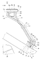
- FIG. 4 is a left side view showing how the path member 51, the drain pipe 52, and the breather pipe 53 are routed.
- FIG. 5 is a cross-sectional view taken along line VV of FIG. 2, showing cross-sections of the cap mounting portion 50 and the tank cap 40.
- the cap attachment portion 50 is a recess formed by partially recessing the upper surface portion 29a downward, and the tank cap 40 is arranged in this recess.
- the cap attachment portion 50 includes an annular peripheral wall portion 50a surrounding the tank cap 40 from its periphery, a bottom portion 50b forming the bottom surface of the recess, and an oil filler opening 50c passing through the bottom portion 50b.
- the peripheral wall portion 50a extends upward from the peripheral edge of the disk-shaped bottom portion 50b.
- the fuel filler port 50c is provided at the center of the bottom surface portion 50b in plan view.
- the tank cap 40 covers and closes the fuel filler port 50c from above. The fuel is injected into the fuel tank 29 through the filler port 50c with the tank cap 40 opened.
- the cap attachment portion 50 receives fuel spilled around the fuel filler port 50c during fueling.
- the path member 51, the drain pipe 52, and the breather pipe 53 extend downward from the cap mounting portion 50 and are connected to the lower surface portion 29c (FIG. 4) of the fuel tank 29, respectively.
- the lower surface portion 29c has a tank bottom wall portion 35 at the rear portion of the fuel tank 29, which slopes rearwardly downward when viewed from the side of the vehicle.
- the tank bottom wall portion 35 is inclined rearwardly downward along the main frame 19a.
- the tank bottom wall portion 35 is located above the main frame 19a and between the left and right main frames 19a.
- the tank bottom wall portion 35 is positioned behind and below the cap attachment portion 50 .
- the drain pipe 52 is a pipe that vertically penetrates the fuel tank 29 .
- the drain pipe 52 drains water and fuel received by the cap attachment portion 50 to the outside of the fuel tank 29 .
- An upper end portion 52a of the drain pipe 52 is connected to a portion of the bottom surface portion 50b of the cap attachment portion 50 surrounding the oil supply port 50c.
- the upper end surface of the drain pipe 52 opens above the bottom surface portion 50b.
- the drain pipe 52 extends diagonally rearward and downward inside the fuel tank 29 from the bottom surface portion 50b.
- a lower end portion 52 b (one end portion of the pipe) of the drain pipe 52 is connected to the tank bottom wall portion 35 .
- the tank bottom wall portion 35 includes a drain pipe connection portion 35a (pipe connection portion) to which the lower end portion 52b is connected.
- the drain pipe connecting portion 35a is a hole into which the lower end portion 52b is fitted.
- the lower end portion 52b is fitted to the drain pipe connection portion 35a and is coupled to the drain pipe connection portion 35a by welding, for example. Since the lower end portion 52b is arranged orthogonally to the tank bottom wall portion 35 which is downwardly rearward, it extends upwardly rearward when viewed from the side of the vehicle.
- the drain pipe 52 bends forward and upward toward the cap attachment portion 50 above the lower end portion 52 b and extends upward toward the cap attachment portion 50 .
- a drain tube 55 is connected to a portion where the lower end portion 52b of the drain pipe 52 protrudes downward from the tank bottom wall portion 35 .
- the drain tube 55 extends downward and opens downward at the lower portion of the vehicle body.
- the drain tube 55 is made of rubber, for example.
- the breather pipe 53 is a pipe that vertically penetrates the fuel tank 29 .
- the breather pipe 53 communicates the inside of the fuel tank 29 with the atmosphere.
- the bottom surface portion 50b of the cap attachment portion 50 is provided with a breather pipe upper connection portion 56 to which the upper end portion 53a of the breather pipe 53 is connected.
- the breather pipe upper connection portion 56 is a hole into which the upper end portion 53a is fitted.
- the breather pipe upper connecting portion 56 is arranged around the fuel filler port 50c.
- the upper end portion 53a is fitted into the breather pipe upper connection portion 56 and is coupled to the breather pipe upper connection portion 56 by, for example, welding.
- the upper end surface of the breather pipe 53 opens above the bottom surface portion 50b.
- the breather pipe 53 extends diagonally rearward and downward along the drain pipe 52 in the fuel tank 29 from the bottom surface portion 50b.
- a lower end portion 53 b (one end portion of the pipe) of the breather pipe 53 is connected to the tank bottom wall portion 35 .
- the tank bottom wall portion 35 includes a breather pipe connection portion 35b (pipe connection portion) to which the lower end portion 53b is connected.
- the breather pipe connecting portion 35b is a hole into which the lower end portion 53b is fitted.
- the lower end portion 53b is fitted to the breather pipe connection portion 35b and is coupled to the breather pipe connection portion 35b by, for example, welding. Since the lower end portion 53b is arranged orthogonally to the tank bottom wall portion 35, which extends rearwardly downward, it extends upwardly rearward when viewed from the side of the vehicle.
- the breather pipe 53 bends forward and upward toward the cap attachment portion 50 above the lower end portion 53 b and extends upward toward the cap attachment portion 50 .
- a breather tube 57 is connected to a portion where the lower end portion 53b of the breather pipe 53 protrudes downward from the tank bottom wall portion 35 .
- a lower end of the breather tube 57 opens downward.
- the breather tube 57 is made of rubber, for example.
- the fuel tank 29 has a first opening 61 penetrating through the bottom portion 50 b of the cap mounting portion 50 and a second opening 62 penetrating through the tank bottom wall portion 35 .
- the first opening 61 is arranged around the fuel filler port 50c.
- the second opening 62 is located rearwardly and downwardly with respect to the first opening 61 .
- the path member 51 is a pipe that vertically penetrates the fuel tank 29 and has a hole 51f that axially penetrates the path member 51 .
- the path member 51 connects the first opening 61 and the second opening 62 through the inside of the fuel tank 29 .
- An upper end portion 51a of the path member 51 is fitted into the first opening 61 and coupled to the first opening 61 by welding, for example.
- the upper end surface of the upper end portion 51a opens above the bottom surface portion 50b.
- the upper end 51 a of the path member 51 extends vertically parallel to the axis 40 b of the tank cap 40 .
- parallel also includes substantially parallel.
- the upper end portion 51a and the axis 40b extend substantially vertically.
- the axis 40b coincides with the axis of the filler port 50c.
- the path member 51 extends diagonally rearward and downward inside the fuel tank 29 from the bottom surface portion 50b.
- a lower end portion 51 b of the path member 51 is connected to the second opening 62 of the tank bottom wall portion 35 .
- the lower end portion 51b is fitted into the second opening 62 and coupled to the second opening 62 by welding, for example. Since the lower end portion 51b is arranged orthogonally to the tank bottom wall portion 35 which is downwardly rearward, the lower end portion 51b extends upwardly rearward when viewed from the side of the vehicle.
- the path member 51 includes a lower end portion 51b, a first bent portion 51c that bends forward and upward toward the first opening 61 above the lower end portion 51b, and a first bent portion 51c that bends forward and upward from the first bent portion 51c. It has an inclined portion 51d that extends obliquely, a second bent portion 51e that bends upward from the inclined portion 51d, and an upper end portion 51a that vertically extends upward from the second bent portion 51e.
- the path member 51 is directly connected to the fuel tank 29 only through the first opening 61 and the second opening 62 . That is, the path member 51 does not contact the wall surface of the fuel tank 29 except at the first opening 61 and the second opening 62 . Therefore, the path member 51 can be made shorter than, for example, a structure in which the path member 51 is arranged along the inner surface of the fuel tank 29 .
- the inclined portion 51d of the path member 51 extends in the longitudinal direction and the vertical direction of the vehicle along the drain pipe 52 and the breather tube 57 when viewed from the side of the vehicle.
- the inclined portion 51 d of the path member 51 , the drain pipe 52 and the breather pipe 53 are bundled by a holding member 63 .
- the holding member 63 has a band shape surrounding the inclined portion 51 d , the drain pipe 52 and the breather pipe 53 .
- the first bent portion 51c is closer to the second opening 62 than the second bent portion 51e.
- the first bent portion 51c is closest to the second opening 62 among the first bent portion 51c and the second bent portion 51e.
- a distance L1 between the first bent portion 51c and the second opening 62 in the axial direction of the path member 51 is smaller than a distance L2 between the first bent portion 51c and the first opening 61 . Therefore, the path member 51 can be routed away from the inner surface of the fuel tank 29, and the path member 51 can be shortened.
- FIG. 6 is an enlarged cross-sectional view of the peripheral portion of the first opening 61 in FIG. 5 and 6, the operation cable 41 is routed inside the fuel tank 29 by passing through the hole 51f of the path member 51.
- the operation cable 41 includes a tubular outer tube 65 and an inner cable 66 provided inside the outer tube 65 .
- the inner cable 66 can move in the axial direction of the operation cable 41 inside the outer tube 65 .
- An unlocking mechanism 70 for unlocking the tank cap 40 is provided in the cap mounting portion 50 .
- the unlocking mechanism 70 is arranged above the first opening 61 and between the peripheral wall portion 50 a of the cap attachment portion 50 and the outer circumference of the tank cap 40 .
- the unlocking mechanism 70 includes a lock member 71 that engages with the tank cap 40 and a rotation shaft 72 that rotatably supports the lock member 71 .
- the rotating shaft 72 is a shaft extending in the vehicle width direction.
- the lock member 71 includes a rotating portion 71a supported by a rotating shaft 72 and rotating around the rotating shaft 72, an engaging portion 71b projecting from the rotating portion 71a toward the tank cap 40, and a rotating portion.
- a cable connecting portion 71c extending from 71a in the opposite direction to the engaging portion 71b is provided.
- An engaged portion 40 c with which the engaging portion 71 b of the lock member 71 engages is provided on the outer circumference of the tank cap 40 .
- the engaged portion 40c is, for example, a groove.
- the inner cable 66 extends outward from the upper end of the path member 51 through the first opening 61 and is connected to the cable connecting portion 71 c of the lock member 71 .
- the upper end of the inner cable 66 is provided with a cylindrical connecting member 66a extending in the vehicle width direction.
- the inner cable 66 is connected to the lock member 71 by rotatably fitting the connecting member 66a into the hole provided in the cable connecting portion 71c.
- the upper end of the path member 51 protrudes upward from the bottom surface portion 50b.
- the upper end of the outer tube 65 is flush with the upper end of the path member 51 .
- a cylindrical lid member 73 is attached to the upper end of the path member 51 to close the opening of the upper end of the path member 51 .
- the lid member 73 is attached to the path member 51 by being fitted around the outer periphery of the upper end of the path member 51 .
- the lid member 73 has a cable through-hole 73a vertically penetrating the lid member 73 .
- the inner cable 66 extends upward through the cable through hole 73a and is connected to the cable connecting portion 71c.
- the lid member 73 prevents water and dust from entering the upper end of the path member 51 . Further, the lid member 73 contacts the lock member 71 when the lock member 71 rotates, and stops the rotation of the lock member 71 .
- a lower end portion 51b of the path member 51 protrudes downward from the tank bottom wall portion 35.
- the operation cable 41 extends downward from the lower end of the path member 51 and is connected to the solenoid 42 .
- the operation cable 41 has an inner cable 66 ( FIG. 5 ) connected to the solenoid 42 at its lower end.
- An extension direction 80 of the operation cable 41 extending from the second opening 62 toward the solenoid 42 is forward and downward.
- the connecting direction of the operation cable 41 and the solenoid 42 is the same direction as the extending direction 80 . That is, the operation cable 41 extending straight in the extension direction 80 is connected to the solenoid 42 as it is without changing its direction.
- the driving direction of the solenoid 42 is the same as the extending direction 80 , and the solenoid 42 pulls the inner cable 66 in the extending direction 80 . Therefore, the driving force of the solenoid 42 can be efficiently transmitted to the inner cable 66 .
- the control unit 33 drives and controls the solenoid 42 so that the operation cable 41 is driven by the solenoid 42 .
- the lock member 71 is pulled downward by the inner cable 66 and rotated from the solid line position in FIG. 6 to the virtual line position.
- the engaging portion 71b is disengaged from the engaged portion 40c, and the tank cap 40 is unlocked.
- the tank cap 40 is rotatable around a hinge provided at the rear portion of the tank cap 40, for example. The tank cap 40 is opened by rotating upward about the hinge in the unlocked state.
- the locking member 71 of the unlocking mechanism 70 abuts against the upper surface 73b of the lid member 73, and the limit position of rotation is restricted. Therefore, the rotation of the lock member 71 can be restricted using the lid member 73, and the rotation of the lock member 71 can be restricted with a simple structure. Since excessive rotation of the lock member 71 is restricted by the lid member 73, the load on the inner cable 66 during the unlocking operation can be reduced. Therefore, even if the inner cable 66 is not thickened, the lock can be unlocked satisfactorily.
- the operation cable 41 is passed through the path member 51 routed inside the fuel tank 29, so it is not exposed to the outside of the fuel tank 29. Therefore, the operation cable 41 is inconspicuous, and the appearance of the straddle-type vehicle 10 is good. Further, the operation cable 41 is guided by the path member 51 along the entire path from the first opening 61 to the second opening 62 . Therefore, the wiring route of the operation cable 41 is stabilized, and the operation cable 41 can be operated satisfactorily.
- the second opening 62, the drain pipe connecting portion 35a, and the breather pipe connecting portion 35b are provided adjacent to each other in the tank bottom wall portion 35. That is, the lower end portion 51 b of the path member 51 , the lower end portion 52 b of the drain pipe 52 , and the lower end portion 53 b of the breather pipe 53 are provided adjacent to each other in the tank bottom wall portion 35 . Also, the lower end portion 51b, the lower end portion 52b, and the lower end portion 53b are provided substantially parallel to each other.
- the lower end portion 51b, the lower end portion 52b, and the lower end portion 53b can be collectively arranged in the tank bottom wall portion 35 in a compact manner, and the routing of the path member 51, the drain pipe 52, and the breather pipe 53 is easy.
- the saddle-ride type vehicle 10 includes the fuel tank 29, the tank cap 40 that opens and closes the fuel filler port 50c provided in the fuel tank 29,
- the fuel tank 29 is provided with a first opening 61 and a second opening 62 that pass through the fuel tank 29 and pass through the inside of the fuel tank 29 to the first opening 62 .
- a path member 51 is provided to connect the opening 61 and the second opening 62, the operation cable 41 is routed in the path member 51, and the operation cable 41 coming out from the first opening 61 is connected to the tank cap.
- 40 is connected to an unlocking mechanism 70 for unlocking 40 .
- the operation cable 41 since the operation cable 41 is routed in the path member 51 passing through the inside of the fuel tank 29, the operation cable 41 can be hidden with a simple structure and routed with good appearance. Also, the operation cable 41 is guided by the path member 51 from the second opening 62 to the first opening 61 . Therefore, the wiring route of the operation cable 41 is stabilized, and the operation cable 41 can be operated satisfactorily.
- the path member 51 is pipe-shaped and connected to the fuel tank 29 only through the first opening 61 and the second opening 62 . According to this configuration, the route member 51 can be routed in a short route, and the operation cable 41 can be shortened.
- the path member 51 has a first bent portion 51c (bent portion) and a second bent portion 51e (bent portion) between the first opening portion 61 and the second opening portion 62, and the first bent portion 51c Of the second bent portions 51e, the first bent portion 51c closest to the second opening 62 in the axial direction of the path member 51 bends toward the first opening 61, and in the axial direction of the path member 51, A distance L1 between the first bent portion 51c and the second opening 62 is smaller than a distance L2 between the first bent portion 51c and the first opening 61 . According to this configuration, the route member 51 can be routed in a short route, and the operation cable 41 can be shortened.
- a lid member 73 is provided to close the end of the path member 51 on the first opening 61 side, and the operation cable 41 extends outside through the lid member 73 and is connected to the unlocking mechanism 70 . According to this configuration, the cover member 73 can effectively prevent water and dust from entering the path member 51 .
- the unlocking mechanism 70 contacts the lid member 73 during the unlocking operation. According to this configuration, the operation of the unlocking mechanism 70 can be stopped using the lid member 73, so that the operation of the unlocking mechanism 70 can be stopped without using a dedicated member for stopping the unlocking mechanism 70. Moreover, since the load on the operation cable 41 can be reduced when the operation of the unlocking mechanism 70 is stopped, the unlocking operation can be performed satisfactorily without making the operation cable 41 thicker.
- a drain pipe 52 and a breather pipe 53 are routed in the fuel tank 29 separately from the path member 51, and the path member 51, the drain pipe 52, and the breather pipe 53 are bundled. According to this configuration, the drain pipe 52 and the breather pipe 53 can be used in the fuel tank 29 to support the path member 51 with a simple structure. At least one of the drain pipe 52 and the breather pipe 53 should be bundled with the path member 51 .
- the fuel tank 29 also includes a drain pipe connection portion 35a to which the lower end portion 52b of the drain pipe 52 is connected, and a breather pipe connection portion 35b to which the lower end portion 53b of the breather pipe 53 is connected. Extending outward from the connecting portion 35a, the breather pipe 53 extends outward from the breather pipe connecting portion 35b, and the second opening 62 is provided adjacent to the drain pipe connecting portion 35a and the breather pipe connecting portion 35b. According to this configuration, since the second opening 62, the drain pipe connection portion 35a, and the breather pipe connection portion 35b are adjacent to each other, the path member 51, the drain pipe 52, and the breather pipe 53 can be arranged together. Therefore, routing of the path member 51, the drain pipe 52, and the breather pipe 53 within the fuel tank 29 is easy.
- the second opening 62 may be adjacent to at least one of the drain pipe connecting portion 35a and the breather pipe connecting portion 35b.
- the path member 51 includes an inclined portion 51d that obliquely extends in the vehicle front-rear direction and the up-down direction within the fuel tank 29 when viewed from the side of the vehicle. According to this configuration, the route member 51 can be routed in a short route, and the operation cable 41 can be shortened.
- the path member 51 is attached to the fuel tank 29 in parallel with the axis 40 b of the tank cap 40 at the first opening 61 .
- the operation cable 41 is also parallel to the axis 40 b of the tank cap 40 . Therefore, the operation cable 41 can be arranged near the tank cap 40, and the operation cable 41 can be shortened.
- the unlocking mechanism 70 also includes a lock member 71 that engages with the tank cap 40 to lock the tank cap 40.
- the operation cable 41 is connected to the lock member 71 and operates the lock member 71 to unlock. do. According to this configuration, the operation cable 41 is connected to the tank cap 40 via the lock member 71 . Therefore, the load acting on the operation cable 41 from the tank cap 40 side is relieved by the lock member 71 . Therefore, the operation cable 41 has good durability.
- a solenoid 42 is provided to drive the operation cable 41.
- the operation cable 41 extending outward from the second opening 62 is connected to the solenoid 42.
- the solenoid 42 is arranged below the upper surface 40a of the tank cap 40. be. With this configuration, the solenoid 42 can be compactly arranged below the upper surface 40 a of the tank cap 40 . In addition, since it is difficult to access the solenoid 42 from the outside, the anti-theft property is good. Furthermore, since the solenoid 42 can be arranged near the battery 34 , the solenoid 42 can be easily connected to the battery 34 via the electric wire 34 a and the electric wire 43 .
- extension direction 80 of the operation cable 41 extending outward from the second opening 62 and the connection direction of the operation cable 41 and the solenoid 42 are the same. According to this configuration, the driving force of the solenoid 42 can be efficiently transmitted to the operation cable 41, and the operation cable 41 can be operated satisfactorily.
- a control section 33 for controlling the driving of the solenoid 42 is provided, and the control section 33 is arranged below the upper surface 40 a of the tank cap 40 .
- the controller 33 can be compactly arranged below the upper surface 40 a of the tank cap 40 .
- the solenoid 42 can be arranged near the control unit 33 , the solenoid 42 and the control unit 33 can be easily connected with a short electric wire 43 .
- the solenoid 42 is arranged below the fuel tank 29 . With this configuration, the solenoid 42 can be compactly arranged below the fuel tank 29 . In addition, since it is difficult to access the solenoid 42 from the outside, the anti-theft property is good. Furthermore, since the solenoid 42 can be arranged near the battery 34 , the solenoid 42 can be easily connected to the battery 34 via the electric wire 34 a and the electric wire 43 .
- control unit 33 is arranged below the fuel tank 29 . According to this configuration, the controller 33 can be compactly arranged below the fuel tank 29 . Also, since the solenoid 42 can be arranged near the control unit 33 , the solenoid 42 and the control unit 33 can be easily connected with a short electric wire 43 .
- the above-described embodiment shows one mode to which the present invention is applied, and the present invention is not limited to the above-described embodiment.
- the path member 51 is connected to the fuel tank 29 only through the first opening 61 and the second opening 62, but the present invention is not limited to this.
- the path member 51 may be provided in contact with the inner surface of the fuel tank 29 along the inner surface of the fuel tank 29 in the section between the first opening 61 and the second opening 62 .
- the lower end portion 51b of the path member 51 is arranged perpendicular to the tank bottom wall portion 35, but the present invention is not limited to this.
- the lower end portion 51b may be arranged to penetrate the tank bottom wall portion 35 in the vertical direction.
- the extending direction of the operation cable 41 extending downward from the second opening 62 is the vertical direction
- the driving direction of the solenoid 42 is also set to the vertical direction.
- the solenoid 42 and the control unit 33 are arranged below the upper surface 40a of the tank cap 40 and below the fuel tank 29, but the present invention is limited to this. not.
- the solenoid 42 and the controller 33 may be arranged below the upper surface 40a of the tank cap 40 and below the rear seat 17b.
- the saddle type vehicle 10 has been described by taking a motorcycle as an example, but the present invention is not limited to this. It is applicable to wheeled vehicles and saddle type vehicles with four or more wheels.
- a straddle-type vehicle comprising a fuel tank, a tank cap that openably and closably covers a fuel filler port provided in the fuel tank, and an operation cable for unlocking the tank cap, wherein the fuel tank is a first opening and a second opening penetrating the fuel tank, and a path member passing through the fuel tank and connecting the first opening and the second opening; 2.
- (Arrangement 2) The straddle-type vehicle according to Arrangement 1, wherein the path member is pipe-shaped and connected to the fuel tank only through the first opening and the second opening. According to this configuration, the route member can be routed in a short route, and the operation cable can be shortened.
- the path member has at least one bent portion between the first opening and the second opening, and the second opening is formed in the bent portion in the axial direction of the path member. is bent toward the first opening side, and the distance between the first bent portion and the second opening in the axial direction of the path member is equal to the first bent portion and the first opening. According to this configuration, the route member can be routed in a short route, and the operation cable can be shortened.
- a lid member is provided to close the end of the path member on the first opening side, and the operation cable extends outward through the lid member and is connected to the unlocking mechanism.
- a straddle-type vehicle according to any one of configurations 1 to 3, characterized by: According to this configuration, the cover member can effectively prevent water and dust from entering the path member.
- the fuel tank includes a pipe connection portion to which one end portion of the pipe is connected, the pipe extends outward from the pipe connection portion, and the second opening is at the pipe connection portion.
- the unlocking mechanism includes a lock member that engages with the tank cap to lock the tank cap, and the operation cable is connected to the lock member and operates the lock member to unlock the tank cap.
- a straddle-type vehicle according to any one of configurations 1 to 9, characterized in that it is released. According to this configuration, the operating cable is connected to the tank cap via the locking member. Therefore, the load acting on the operation cable from the tank cap side is alleviated by the lock member. Therefore, the durability of the operation cable is good.
- a solenoid is provided for driving the operation cable, the operation cable extending outward from the second opening is connected to the solenoid, and the solenoid is arranged below the upper surface of the tank cap.
- the straddle-type vehicle according to any one of configurations 1 to 10, characterized in that: With this configuration, the solenoid can be arranged compactly below the upper surface of the tank cap.
- the control section can be arranged compactly below the upper surface of the tank cap.
- the solenoid and the controller are arranged below the upper surface of the tank cap, the solenoid and the controller can be easily connected.
Landscapes
- Engineering & Computer Science (AREA)
- Mechanical Engineering (AREA)
- Life Sciences & Earth Sciences (AREA)
- Sustainable Development (AREA)
- Sustainable Energy (AREA)
- Chemical & Material Sciences (AREA)
- Combustion & Propulsion (AREA)
- Transportation (AREA)
- Cooling, Air Intake And Gas Exhaust, And Fuel Tank Arrangements In Propulsion Units (AREA)
Abstract
タンクキャップの操作ケーブルを簡単な構造で外観性良く配索し、且つ、操作ケーブルを良好に操作できるようにする。 鞍乗り型車両は、燃料タンク(29)と、燃料タンク(29)に設けられた給油口(50c)を開閉可能に覆うタンクキャップ(40)と、タンクキャップ(40)の開錠動作を行う操作ケーブル(41)とを備え、燃料タンク(29)は、燃料タンク(29)を貫通する第1開口部(61)及び第2開口部を備え、燃料タンク(29)内を通って第1開口部(61)と第2開口部とを接続する経路部材(51)が設けられ、操作ケーブル(41)は、経路部材(51)内に配索され、第1開口部(61)から外側に出る操作ケーブル(41)は、タンクキャップ(40)を開錠する開錠機構(70)に接続される。
Description
本発明は、鞍乗り型車両に関する。
従来、タンクキャップに設けられたエアーベントノブと燃料コックのバルブとを接続する鋼線(操作ケーブル)が、燃料タンク内に配索される構造が知られている(例えば、特許文献1参照)。特許文献1では、エアーベントノブの操作は、鋼線を介してバルブに伝達される。この鋼線は、燃料タンク内に露出した状態で燃料タンク内に配索される。
ところで、鞍乗り型車両の燃料タンクでは、タンクキャップの開錠を操作する操作ケーブルを燃料タンクの外側に配索する場合がある。この場合、外観性の向上を目的として操作ケーブルを隠すカバーが設けられるため、部品点数が増加する。また、上記従来の燃料タンクでは、操作ケーブルとしての鋼線が燃料タンク内に露出しているため、鋼線の配索経路が安定せず、操作対象の操作をし難くなることが考えられる。
本発明は、上述した事情に鑑みてなされたものであり、タンクキャップの操作ケーブルを簡単な構造で外観性良く配索し、且つ、操作ケーブルを良好に操作できるようにすることを目的とする。
本発明は、上述した事情に鑑みてなされたものであり、タンクキャップの操作ケーブルを簡単な構造で外観性良く配索し、且つ、操作ケーブルを良好に操作できるようにすることを目的とする。
この明細書には、2021年5月12日に出願された日本国特許出願・特願2021-080929の全ての内容が含まれる。
鞍乗り型車両は、燃料タンクと、前記燃料タンクに設けられた給油口を開閉可能に覆うタンクキャップと、前記タンクキャップの開錠動作を行う操作ケーブルとを備える鞍乗り型車両において、前記燃料タンクは、前記燃料タンクを貫通する第1開口部及び第2開口部を備え、前記燃料タンク内を通って前記第1開口部と前記第2開口部とを接続する経路部材を備え、前記操作ケーブルは、前記経路部材内に配索され、前記第1開口部から外側に出る前記操作ケーブルは、前記タンクキャップを開錠する開錠機構に接続されることを特徴とする。
鞍乗り型車両は、燃料タンクと、前記燃料タンクに設けられた給油口を開閉可能に覆うタンクキャップと、前記タンクキャップの開錠動作を行う操作ケーブルとを備える鞍乗り型車両において、前記燃料タンクは、前記燃料タンクを貫通する第1開口部及び第2開口部を備え、前記燃料タンク内を通って前記第1開口部と前記第2開口部とを接続する経路部材を備え、前記操作ケーブルは、前記経路部材内に配索され、前記第1開口部から外側に出る前記操作ケーブルは、前記タンクキャップを開錠する開錠機構に接続されることを特徴とする。
タンクキャップの操作ケーブルを簡単な構造で外観性良く配索し、且つ、操作ケーブルを良好に操作できる。
以下、図面を参照して本発明の実施の形態について説明する。なお、説明中、前後左右および上下といった方向の記載は、特に記載がなければ車体に対する方向と同一とする。また、各図に示す符号FRは車体前方を示し、符号UPは車体上方を示し、符号LHは車体左方を示す。
[実施の形態]
図1は、本発明の実施の形態に係る鞍乗り型車両10の側面図である。
鞍乗り型車両10は、車体フレーム11と、車体フレーム11に支持されるパワーユニット12と、前輪13を操舵自在に支持するフロントフォーク14と、後輪15を支持するスイングアーム16と、乗員用のシート17とを備える車両である。
鞍乗り型車両10は、乗員がシート17に跨るようにして着座する車両である。シート17は、車体フレーム11の後部の上方に設けられる。
図1は、本発明の実施の形態に係る鞍乗り型車両10の側面図である。
鞍乗り型車両10は、車体フレーム11と、車体フレーム11に支持されるパワーユニット12と、前輪13を操舵自在に支持するフロントフォーク14と、後輪15を支持するスイングアーム16と、乗員用のシート17とを備える車両である。
鞍乗り型車両10は、乗員がシート17に跨るようにして着座する車両である。シート17は、車体フレーム11の後部の上方に設けられる。
車体フレーム11は、車体フレーム11の前端部に設けられるヘッドパイプ18と、ヘッドパイプ18の後方に位置するフロントフレーム19と、フロントフレーム19の後方に位置するリアフレーム20とを備える。フロントフレーム19の前端部は、ヘッドパイプ18に接続される。
シート17は、リアフレーム20に支持される。
シート17は、リアフレーム20に支持される。
フロントフォーク14は、ヘッドパイプ18によって左右に操舵自在に支持される。前輪13は、フロントフォーク14の下端部に設けられる車軸13aに支持される。乗員が把持する操舵用のハンドル21は、フロントフォーク14の上端部に取り付けられる。
スイングアーム16は、車体フレーム11に支持されるピボット軸22に支持される。ピボット軸22は、車幅方向に水平に延びる軸である。スイングアーム16の前端部には、ピボット軸22が挿通される。スイングアーム16は、ピボット軸22を中心に上下に揺動する。
後輪15は、スイングアーム16の後端部に設けられる車軸15aに支持される。
後輪15は、スイングアーム16の後端部に設けられる車軸15aに支持される。
パワーユニット12は、前輪13と後輪15との間に配置され、車体フレーム11に支持される。
パワーユニット12は、内燃機関である。パワーユニット12は、クランクケース23と、往復運動するピストンを収容するシリンダー部24とを備える。シリンダー部24の排気ポートには、排気装置25が接続される。
パワーユニット12の出力は、パワーユニット12と後輪15とを接続する駆動力伝達部材によって後輪15に伝達される。
パワーユニット12は、内燃機関である。パワーユニット12は、クランクケース23と、往復運動するピストンを収容するシリンダー部24とを備える。シリンダー部24の排気ポートには、排気装置25が接続される。
パワーユニット12の出力は、パワーユニット12と後輪15とを接続する駆動力伝達部材によって後輪15に伝達される。
また、鞍乗り型車両10は、前輪13を上方から覆うフロントフェンダー26と、後輪15を上方から覆うリアフェンダー27と、乗員が足を載せるステップ28と、パワーユニット12が使用する燃料を蓄える燃料タンク29とを備える。
フロントフェンダー26は、フロントフォーク14に取り付けられる。リアフェンダー27及びステップ28は、シート17よりも下方に設けられる。燃料タンク29は、車体フレーム11に支持される。
フロントフェンダー26は、フロントフォーク14に取り付けられる。リアフェンダー27及びステップ28は、シート17よりも下方に設けられる。燃料タンク29は、車体フレーム11に支持される。
フロントフレーム19は、ヘッドパイプ18から後下方に延びる左右一対のメインフレーム19aと、メインフレーム19aの後端部から下方に延びる左右一対のピボットフレーム19bと、ヘッドパイプ18においてメインフレーム19aの前端の下方の位置から下方に延びる左右一対のダウンフレーム19cとを備える。
図2は、鞍乗り型車両10を上方から見た平面図である。
図1及び図2を参照し、鞍乗り型車両10は、車体フレーム11等によって構成される車体を覆う車体カバーとして、ヘッドパイプ18を前方から覆うフロントカバー31と、車体フレーム11の前端部を車幅方向外側から覆う左右一対のサイドカバー32とを備える。
図1及び図2を参照し、鞍乗り型車両10は、車体フレーム11等によって構成される車体を覆う車体カバーとして、ヘッドパイプ18を前方から覆うフロントカバー31と、車体フレーム11の前端部を車幅方向外側から覆う左右一対のサイドカバー32とを備える。
燃料タンク29は、車両前後方向で、ヘッドパイプ18とシート17との間に配置される。燃料タンク29は、左右のメインフレーム19aの上方に配置され、メインフレーム19aによって支持される。
燃料タンク29の前部の上面には、燃料タンク29を開閉可能に覆うタンクキャップ40が設けられる。タンクキャップ40は、車幅方向の中央部に配置される。
シート17は、運転者が着座する前側シート17aと、同乗者が着座する後側シート17bとを一体に備える。後側シート17bは、前側シート17aの後方で、前側シート17aに対し段状に高く設けられる。前側シート17aの前端部は、燃料タンク29の後部を上方から覆う。燃料タンク29の上面は、後側シート17bの上面よりも高い位置にある。
燃料タンク29の前部の上面には、燃料タンク29を開閉可能に覆うタンクキャップ40が設けられる。タンクキャップ40は、車幅方向の中央部に配置される。
シート17は、運転者が着座する前側シート17aと、同乗者が着座する後側シート17bとを一体に備える。後側シート17bは、前側シート17aの後方で、前側シート17aに対し段状に高く設けられる。前側シート17aの前端部は、燃料タンク29の後部を上方から覆う。燃料タンク29の上面は、後側シート17bの上面よりも高い位置にある。
パワーユニット12等の鞍乗り型車両10の各部を電子的に制御する制御部33は、燃料タンク29の後部の下方に配置される。制御部33は、シリンダー部24よりも後方且つクランクケース23の後部の上方で、左右のメインフレーム19aの後部の間に配置される。
鞍乗り型車両10の各部に電力を供給するバッテリー34は、前側シート17aの下方に配置され、前側シート17aによって上方から覆われる。バッテリー34は、制御部33の後方で燃料タンク29よりも下方に配置される。バッテリー34は、バッテリー34から前方に延びる電線34aによって制御部33に接続される。
鞍乗り型車両10の各部に電力を供給するバッテリー34は、前側シート17aの下方に配置され、前側シート17aによって上方から覆われる。バッテリー34は、制御部33の後方で燃料タンク29よりも下方に配置される。バッテリー34は、バッテリー34から前方に延びる電線34aによって制御部33に接続される。
鞍乗り型車両10は、タンクキャップ40の開錠動作を行う操作ケーブル41と、操作ケーブルを駆動するソレノイド42とを備える。
操作ケーブル41は、ソレノイド42に接続される。ソレノイド42は、電線43によって制御部33に接続される。
制御部33は、ソレノイド42を駆動制御して操作ケーブル41を駆動し、タンクキャップ40を開錠する。
操作ケーブル41は、ソレノイド42に接続される。ソレノイド42は、電線43によって制御部33に接続される。
制御部33は、ソレノイド42を駆動制御して操作ケーブル41を駆動し、タンクキャップ40を開錠する。
ソレノイド42は、燃料タンク29の下方に配置される。ソレノイド42は、シリンダー部24よりも後方且つクランクケース23の後部の上方で、左右のメインフレーム19aの後部の間に配置される。ソレノイド42は、制御部33の前上方に配置される。
ソレノイド42及び制御部33は、タンクキャップ40の上面40aよりも下方に配置される。燃料タンク29は、平面視では、ソレノイド42及び制御部33に上方から重なる。
ソレノイド42及び制御部33は、タンクキャップ40の上面40aよりも下方に配置される。燃料タンク29は、平面視では、ソレノイド42及び制御部33に上方から重なる。
図3は、燃料タンク29の周辺部の左側面図である。
車両側面視では、燃料タンク29の上面部29aは、燃料タンク29の前部において略水平である。車両側面視では、燃料タンク29の後面部29bは、上面部29aの後端から後下がりに延びる傾斜面である。
燃料タンク29の上面部29aには、タンクキャップ40が取り付けられるキャップ取付部50が設けられる。
燃料タンク29内には、操作ケーブル41が通される経路部材51と、ドレンパイプ52と、ブリーザーパイプ53とが配索される。経路部材51、ドレンパイプ52、及びブリーザーパイプ53は、例えば金属製である。
車両側面視では、燃料タンク29の上面部29aは、燃料タンク29の前部において略水平である。車両側面視では、燃料タンク29の後面部29bは、上面部29aの後端から後下がりに延びる傾斜面である。
燃料タンク29の上面部29aには、タンクキャップ40が取り付けられるキャップ取付部50が設けられる。
燃料タンク29内には、操作ケーブル41が通される経路部材51と、ドレンパイプ52と、ブリーザーパイプ53とが配索される。経路部材51、ドレンパイプ52、及びブリーザーパイプ53は、例えば金属製である。
図4は、経路部材51、ドレンパイプ52、及びブリーザーパイプ53の配索状態を示す左側面図である。図5は、図2のV-V断面図であり、キャップ取付部50及びタンクキャップ40の断面を示す。
キャップ取付部50は、上面部29aの一部が下方に凹む凹部であり、この凹部内にタンクキャップ40が配置される。キャップ取付部50は、タンクキャップ40を周囲から囲む円環状の周壁部50aと、上記凹部の底面を構成する底面部50bと、底面部50bを貫通する給油口50cとを備える。周壁部50aは、円板状の底面部50bの周縁から上方に延出する。給油口50cは、平面視で底面部50bの中心部に設けられる。
タンクキャップ40は、給油口50cを上方から覆って塞ぐ。燃料は、タンクキャップ40を開いた状態で、給油口50cから燃料タンク29内に注入される。キャップ取付部50は、給油の際に給油口50cの周囲に零れた燃料を受ける。
キャップ取付部50は、上面部29aの一部が下方に凹む凹部であり、この凹部内にタンクキャップ40が配置される。キャップ取付部50は、タンクキャップ40を周囲から囲む円環状の周壁部50aと、上記凹部の底面を構成する底面部50bと、底面部50bを貫通する給油口50cとを備える。周壁部50aは、円板状の底面部50bの周縁から上方に延出する。給油口50cは、平面視で底面部50bの中心部に設けられる。
タンクキャップ40は、給油口50cを上方から覆って塞ぐ。燃料は、タンクキャップ40を開いた状態で、給油口50cから燃料タンク29内に注入される。キャップ取付部50は、給油の際に給油口50cの周囲に零れた燃料を受ける。
経路部材51、ドレンパイプ52、及びブリーザーパイプ53は、キャップ取付部50から下方に延び、燃料タンク29の下面部29c(図4)にそれぞれ接続される。下面部29cは、車両側面視で後下がりに傾斜するタンク底壁部35を、燃料タンク29の後部に備える。
タンク底壁部35は、メインフレーム19aに沿うように後下がりに傾斜している。タンク底壁部35は、メインフレーム19aの上方において、左右のメインフレーム19aの間に位置する。タンク底壁部35は、キャップ取付部50の後下方に位置する。
タンク底壁部35は、メインフレーム19aに沿うように後下がりに傾斜している。タンク底壁部35は、メインフレーム19aの上方において、左右のメインフレーム19aの間に位置する。タンク底壁部35は、キャップ取付部50の後下方に位置する。
ドレンパイプ52は、燃料タンク29を上下に貫通するパイプである。ドレンパイプ52は、キャップ取付部50に受けられた水や燃料を燃料タンク29の外に排出する。ドレンパイプ52の上端部52aは、キャップ取付部50の底面部50bにおける給油口50cの周囲の部分に接続される。ドレンパイプ52の上端面は、底面部50bの上方に開口する。ドレンパイプ52は、底面部50bから、燃料タンク29内を後下方に斜めに延びる。
ドレンパイプ52の下端部52b(パイプの一端部)は、タンク底壁部35に接続される。タンク底壁部35は、下端部52bが接続されるドレンパイプ接続部35a(パイプ接続部)を備える。ドレンパイプ接続部35aは、下端部52bが嵌合する孔部である。下端部52bは、ドレンパイプ接続部35aに嵌合され、例えば溶接によってドレンパイプ接続部35aに結合される。
下端部52bは、後下がりのタンク底壁部35に対し直交して配置されるため、車両側面視で後上がりに延びる。ドレンパイプ52は、下端部52bの上方でキャップ取付部50側に向けて前上方に屈曲し、キャップ取付部50に向けて上方に延びる。
下端部52bは、後下がりのタンク底壁部35に対し直交して配置されるため、車両側面視で後上がりに延びる。ドレンパイプ52は、下端部52bの上方でキャップ取付部50側に向けて前上方に屈曲し、キャップ取付部50に向けて上方に延びる。
ドレンパイプ52の下端部52bがタンク底壁部35から下方に突出した部分には、ドレンチューブ55が接続される。ドレンチューブ55は、下方に延出し、車体の下部で下方に開口する。ドレンチューブ55は、例えばゴム製である。
ブリーザーパイプ53は、燃料タンク29を上下に貫通するパイプである。ブリーザーパイプ53は、燃料タンク29内を大気に連通させる。
キャップ取付部50の底面部50bには、ブリーザーパイプ53の上端部53aが接続されるブリーザーパイプ上側接続部56が設けられる。ブリーザーパイプ上側接続部56は、上端部53aが嵌合する孔部である。ブリーザーパイプ上側接続部56は、給油口50cの周囲に配置される。上端部53aは、ブリーザーパイプ上側接続部56に嵌合され、例えば溶接によってブリーザーパイプ上側接続部56に結合される。
ブリーザーパイプ53の上端面は、底面部50bの上方に開口する。ブリーザーパイプ53は、底面部50bから、燃料タンク29内をドレンパイプ52に沿うように後下方へ斜めに延びる。
キャップ取付部50の底面部50bには、ブリーザーパイプ53の上端部53aが接続されるブリーザーパイプ上側接続部56が設けられる。ブリーザーパイプ上側接続部56は、上端部53aが嵌合する孔部である。ブリーザーパイプ上側接続部56は、給油口50cの周囲に配置される。上端部53aは、ブリーザーパイプ上側接続部56に嵌合され、例えば溶接によってブリーザーパイプ上側接続部56に結合される。
ブリーザーパイプ53の上端面は、底面部50bの上方に開口する。ブリーザーパイプ53は、底面部50bから、燃料タンク29内をドレンパイプ52に沿うように後下方へ斜めに延びる。
ブリーザーパイプ53の下端部53b(パイプの一端部)は、タンク底壁部35に接続される。タンク底壁部35は、下端部53bが接続されるブリーザーパイプ接続部35b(パイプ接続部)を備える。ブリーザーパイプ接続部35bは、下端部53bが嵌合する孔部である。下端部53bは、ブリーザーパイプ接続部35bに嵌合され、例えば溶接によってブリーザーパイプ接続部35bに結合される。
下端部53bは、後下がりのタンク底壁部35に対し直交して配置されるため、車両側面視で後上がりに延びる。ブリーザーパイプ53は、下端部53bの上方でキャップ取付部50側に向けて前上方に屈曲し、キャップ取付部50に向けて上方に延びる。
下端部53bは、後下がりのタンク底壁部35に対し直交して配置されるため、車両側面視で後上がりに延びる。ブリーザーパイプ53は、下端部53bの上方でキャップ取付部50側に向けて前上方に屈曲し、キャップ取付部50に向けて上方に延びる。
ブリーザーパイプ53の下端部53bがタンク底壁部35から下方に突出した部分には、ブリーザーチューブ57が接続される。ブリーザーチューブ57の下端部は、下方に開口する。ブリーザーチューブ57は、例えばゴム製である。
燃料タンク29は、キャップ取付部50の底面部50bを貫通する第1開口部61と、タンク底壁部35を貫通する第2開口部62とを備える。第1開口部61は、給油口50cの周囲に配置される。第2開口部62は、第1開口部61に対し後下方に位置する。
経路部材51は、燃料タンク29を上下に貫通するパイプであり、経路部材51を軸方向に貫通する孔51fを備える。経路部材51は、燃料タンク29内を通って第1開口部61と第2開口部62とを接続する。
経路部材51は、燃料タンク29を上下に貫通するパイプであり、経路部材51を軸方向に貫通する孔51fを備える。経路部材51は、燃料タンク29内を通って第1開口部61と第2開口部62とを接続する。
経路部材51の上端部51aは、第1開口部61に嵌合され、例えば溶接によって第1開口部61に結合される。
上端部51aの上端面は、底面部50bの上方に開口する。
第1開口部61において、経路部材51の上端部51aは、タンクキャップ40の軸線40bと平行に上下に延びる。ここで、平行は略平行も含む。上端部51a及び軸線40bは略鉛直に延びる。軸線40bは、給油口50cの軸線に一致する。
経路部材51は、底面部50bから、燃料タンク29内を後下方へ斜めに延びる。
上端部51aの上端面は、底面部50bの上方に開口する。
第1開口部61において、経路部材51の上端部51aは、タンクキャップ40の軸線40bと平行に上下に延びる。ここで、平行は略平行も含む。上端部51a及び軸線40bは略鉛直に延びる。軸線40bは、給油口50cの軸線に一致する。
経路部材51は、底面部50bから、燃料タンク29内を後下方へ斜めに延びる。
経路部材51の下端部51bは、タンク底壁部35の第2開口部62に接続される。下端部51bは、第2開口部62に嵌合され、例えば溶接によって第2開口部62に結合される。
下端部51bは、後下がりのタンク底壁部35に対し直交して配置されるため、車両側面視で後上がりに延びる。
詳細には、経路部材51は、下端部51bと、下端部51bの上方で第1開口部61側に向けて前上方に屈曲する第1屈曲部51cと、第1屈曲部51cから前上方へ斜めに延出する傾斜部51dと、傾斜部51dから上方に向けて屈曲する第2屈曲部51eと、第2屈曲部51eから鉛直に上方に延出する上端部51aとを備える。
下端部51bは、後下がりのタンク底壁部35に対し直交して配置されるため、車両側面視で後上がりに延びる。
詳細には、経路部材51は、下端部51bと、下端部51bの上方で第1開口部61側に向けて前上方に屈曲する第1屈曲部51cと、第1屈曲部51cから前上方へ斜めに延出する傾斜部51dと、傾斜部51dから上方に向けて屈曲する第2屈曲部51eと、第2屈曲部51eから鉛直に上方に延出する上端部51aとを備える。
経路部材51は、第1開口部61及び第2開口部62のみによって燃料タンク29に直接的に接続されている。すなわち、経路部材51は、第1開口部61及び第2開口部62以外では燃料タンク29の壁面に接触していない。このため、例えば、経路部材51を燃料タンク29の内面に沿って配置する構造に比して、経路部材51を短くできる。
経路部材51の傾斜部51dは、ドレンパイプ52及びブリーザーチューブ57に沿うように、車両側面視で車両前後方向且つ上下方向に延びる。
経路部材51の傾斜部51d、ドレンパイプ52及びブリーザーパイプ53は、保持部材63によって束ねられている。保持部材63は、傾斜部51d、ドレンパイプ52及びブリーザーパイプ53を囲むバンド状である。これにより、傾斜部51d、ドレンパイプ52及びブリーザーパイプ53は互いに支え合うことができ、傾斜部51d、ドレンパイプ52及びブリーザーパイプ53を効果的に支持できる。
経路部材51の傾斜部51d、ドレンパイプ52及びブリーザーパイプ53は、保持部材63によって束ねられている。保持部材63は、傾斜部51d、ドレンパイプ52及びブリーザーパイプ53を囲むバンド状である。これにより、傾斜部51d、ドレンパイプ52及びブリーザーパイプ53は互いに支え合うことができ、傾斜部51d、ドレンパイプ52及びブリーザーパイプ53を効果的に支持できる。
経路部材51の軸方向において、第1屈曲部51cは、第2屈曲部51eよりも第2開口部62に近い。第1屈曲部51cは、第1屈曲部51c及び第2屈曲部51eのうち、第2開口部62に最も近い。
経路部材51の軸方向において、第1屈曲部51cと第2開口部62との距離L1は、第1屈曲部51cと第1開口部61との距離L2よりも小さい。このため、経路部材51を燃料タンク29の内面から離間して配索でき、経路部材51を短くできる。
経路部材51の軸方向において、第1屈曲部51cと第2開口部62との距離L1は、第1屈曲部51cと第1開口部61との距離L2よりも小さい。このため、経路部材51を燃料タンク29の内面から離間して配索でき、経路部材51を短くできる。
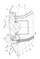
図6は、図5において第1開口部61の周辺部を拡大した断面図である。
図5及び図6を参照し、操作ケーブル41は、経路部材51の孔51f内を通されることで、燃料タンク29の内側に配索される。
操作ケーブル41は、筒状のアウターチューブ65と、アウターチューブ65内に設けられるインナーケーブル66とを備える。インナーケーブル66は、アウターチューブ65内を操作ケーブル41の軸方向に移動可能である。
図5及び図6を参照し、操作ケーブル41は、経路部材51の孔51f内を通されることで、燃料タンク29の内側に配索される。
操作ケーブル41は、筒状のアウターチューブ65と、アウターチューブ65内に設けられるインナーケーブル66とを備える。インナーケーブル66は、アウターチューブ65内を操作ケーブル41の軸方向に移動可能である。
キャップ取付部50内には、タンクキャップ40を開錠する開錠機構70が設けられる。開錠機構70は、第1開口部61の上方において、キャップ取付部50の周壁部50aとタンクキャップ40の外周との間に配置される。
開錠機構70は、タンクキャップ40に係合するロック部材71と、ロック部材71を回動自在に支持する回動軸72とを備える。
回動軸72は、車幅方向に延びる軸である。
ロック部材71は、回動軸72に支持されて回動軸72を中心に回動する回動部71aと、回動部71aからタンクキャップ40側に突出する係合部71bと、回動部71aから係合部71bとは反対側に延出するケーブル連結部71cとを備える。
開錠機構70は、タンクキャップ40に係合するロック部材71と、ロック部材71を回動自在に支持する回動軸72とを備える。
回動軸72は、車幅方向に延びる軸である。
ロック部材71は、回動軸72に支持されて回動軸72を中心に回動する回動部71aと、回動部71aからタンクキャップ40側に突出する係合部71bと、回動部71aから係合部71bとは反対側に延出するケーブル連結部71cとを備える。
タンクキャップ40の外周には、ロック部材71の係合部71bが係合する被係合部40cが設けられる。被係合部40cは例えば溝である。
インナーケーブル66は、第1開口部61を通り経路部材51の上端から外側の上方に延出し、ロック部材71のケーブル連結部71cに連結される。詳細には、インナーケーブル66の上端には、車幅方向に延びる円柱状の接続部材66aが設けられる。インナーケーブル66は、ケーブル連結部71cに設けられた孔部に接続部材66aが回動可能に嵌合することで、ロック部材71に連結される。
インナーケーブル66は、第1開口部61を通り経路部材51の上端から外側の上方に延出し、ロック部材71のケーブル連結部71cに連結される。詳細には、インナーケーブル66の上端には、車幅方向に延びる円柱状の接続部材66aが設けられる。インナーケーブル66は、ケーブル連結部71cに設けられた孔部に接続部材66aが回動可能に嵌合することで、ロック部材71に連結される。
経路部材51の上端は、底面部50bから上方に突出する。アウターチューブ65の上端は、経路部材51の上端と面一に設けられる。経路部材51の上端には、経路部材51の上端の開口を塞ぐ筒状の蓋部材73が取り付けられる。
蓋部材73は、経路部材51の上端の外周に嵌合することで経路部材51に取り付けられる。蓋部材73は、蓋部材73を上下に貫通するケーブル通し孔73aを備える。
インナーケーブル66は、ケーブル通し孔73aを通って上方に延出し、ケーブル連結部71cに接続される。
蓋部材73は、経路部材51の上端への水及び塵埃の侵入を抑制する。
さらに、蓋部材73は、ロック部材71の回動動作時にロック部材71に当接し、ロック部材71の回動を停止させる。
蓋部材73は、経路部材51の上端の外周に嵌合することで経路部材51に取り付けられる。蓋部材73は、蓋部材73を上下に貫通するケーブル通し孔73aを備える。
インナーケーブル66は、ケーブル通し孔73aを通って上方に延出し、ケーブル連結部71cに接続される。
蓋部材73は、経路部材51の上端への水及び塵埃の侵入を抑制する。
さらに、蓋部材73は、ロック部材71の回動動作時にロック部材71に当接し、ロック部材71の回動を停止させる。
図4を参照し、経路部材51の下端部51bは、タンク底壁部35から下方に突出する。
操作ケーブル41は、経路部材51の下端から下方に延出し、ソレノイド42に接続される。詳細には、操作ケーブル41は、インナーケーブル66(図5)の下端がソレノイド42に接続される。
第2開口部62からソレノイド42に向けて延びる操作ケーブル41の延出方向80は前下方である。操作ケーブル41とソレノイド42との接続方向は、延出方向80と同じ方向である。すなわち、延出方向80に真っ直ぐ延びる操作ケーブル41は、向きを変えずにそのままソレノイド42に接続される。ソレノイド42の駆動方向は、延出方向80と同じ方向であり、ソレノイド42は、インナーケーブル66を延出方向80に引く。このため、ソレノイド42の駆動力をインナーケーブル66に効率良く伝達できる。
操作ケーブル41は、経路部材51の下端から下方に延出し、ソレノイド42に接続される。詳細には、操作ケーブル41は、インナーケーブル66(図5)の下端がソレノイド42に接続される。
第2開口部62からソレノイド42に向けて延びる操作ケーブル41の延出方向80は前下方である。操作ケーブル41とソレノイド42との接続方向は、延出方向80と同じ方向である。すなわち、延出方向80に真っ直ぐ延びる操作ケーブル41は、向きを変えずにそのままソレノイド42に接続される。ソレノイド42の駆動方向は、延出方向80と同じ方向であり、ソレノイド42は、インナーケーブル66を延出方向80に引く。このため、ソレノイド42の駆動力をインナーケーブル66に効率良く伝達できる。
図5を参照し、操作ボタン等の操作により、タンクキャップ40を開く指令が入力されると、制御部33は、ソレノイド42を駆動制御し、ソレノイド42によって操作ケーブル41を駆動する。操作ケーブル41が駆動されると、ロック部材71は、インナーケーブル66によって下方に引かれ、図6の実線の位置から仮想線の位置まで回動する。これにより、被係合部40cに対する係合部71bの係合が解除され、タンクキャップ40が開錠される。タンクキャップ40は、例えばタンクキャップ40の後部に設けられるヒンジを中心に回動可能に設けられる。タンクキャップ40は、開錠された状態で上記ヒンジを中心に上方に回動して開く。
また、開錠動作時には、開錠機構70のロック部材71は、蓋部材73の上面73bに当接し、回動の限界位置を規制される。このため、蓋部材73を利用してロック部材71の回動を規制でき、簡単な構造でロック部材71の回動を規制できる。ロック部材71の過度な回動が蓋部材73によって規制されるため、開錠動作時におけるインナーケーブル66の負荷を低減できる。このため、インナーケーブル66を太くしなくとも、良好に開錠を行うことができる。
また、開錠動作時には、開錠機構70のロック部材71は、蓋部材73の上面73bに当接し、回動の限界位置を規制される。このため、蓋部材73を利用してロック部材71の回動を規制でき、簡単な構造でロック部材71の回動を規制できる。ロック部材71の過度な回動が蓋部材73によって規制されるため、開錠動作時におけるインナーケーブル66の負荷を低減できる。このため、インナーケーブル66を太くしなくとも、良好に開錠を行うことができる。
操作ケーブル41は、燃料タンク29内に配索される経路部材51に通されるため、燃料タンク29の外側に露出しない。このため、操作ケーブル41が目立たず、鞍乗り型車両10の外観性が良い。また、操作ケーブル41は、第1開口部61から第2開口部62までの全経路を経路部材51によってガイドされる。このため、操作ケーブル41の配索経路が安定し、操作ケーブル41を良好に操作できる。
図4を参照し、第2開口部62、ドレンパイプ接続部35a、及びブリーザーパイプ接続部35bは、タンク底壁部35において互いに隣接して設けられる。すなわち、経路部材51の下端部51b、ドレンパイプ52の下端部52b、及びブリーザーパイプ53の下端部53bは、タンク底壁部35において互いに隣接して設けられる。また、下端部51b、下端部52b、及び下端部53bは、互いに略平行に設けられる。このため、下端部51b、下端部52b、及び下端部53bをタンク底壁部35にまとめてコンパクトに配置でき、経路部材51、ドレンパイプ52、及びブリーザーパイプ53の配索が容易である。
以上説明したように、本発明を適用した実施の形態によれば、鞍乗り型車両10は、燃料タンク29と、燃料タンク29に設けられた給油口50cを開閉可能に覆うタンクキャップ40と、タンクキャップ40の開錠動作を行う操作ケーブル41とを備え、燃料タンク29は、燃料タンク29を貫通する第1開口部61及び第2開口部62を備え、燃料タンク29内を通って第1開口部61と第2開口部62とを接続する経路部材51が設けられ、操作ケーブル41は、経路部材51内に配索され、第1開口部61から外側に出る操作ケーブル41は、タンクキャップ40を開錠する開錠機構70に接続される。
この構成によれば、操作ケーブル41が、燃料タンク29内を通る経路部材51内に配索されるため、操作ケーブル41を簡単な構造で隠し、外観性良く配索できる。また、操作ケーブル41は、第2開口部62から第1開口部61に亘って経路部材51によって案内される。このため、操作ケーブル41の配索経路が安定し、操作ケーブル41を良好に操作できる。
この構成によれば、操作ケーブル41が、燃料タンク29内を通る経路部材51内に配索されるため、操作ケーブル41を簡単な構造で隠し、外観性良く配索できる。また、操作ケーブル41は、第2開口部62から第1開口部61に亘って経路部材51によって案内される。このため、操作ケーブル41の配索経路が安定し、操作ケーブル41を良好に操作できる。
また、経路部材51は、第1開口部61及び第2開口部62のみによって燃料タンク29に接続されるパイプ状である。
この構成によれば、経路部材51を短い経路で配索でき、操作ケーブル41を短くできる。
この構成によれば、経路部材51を短い経路で配索でき、操作ケーブル41を短くできる。
また、経路部材51は、第1開口部61から第2開口部62までの間に第1屈曲部51c(屈曲部)及び第2屈曲部51e(屈曲部)を有し、第1屈曲部51c及び第2屈曲部51eのうち経路部材51の軸方向において第2開口部62に最も近い第1屈曲部51cは、第1開口部61側に向けて屈曲し、経路部材51の軸方向において、第1屈曲部51cと第2開口部62との距離L1は、第1屈曲部51cと第1開口部61との距離L2よりも小さい。
この構成によれば、経路部材51を短い経路で配索でき、操作ケーブル41を短くできる。
この構成によれば、経路部材51を短い経路で配索でき、操作ケーブル41を短くできる。
さらに、第1開口部61側で経路部材51の端を塞ぐ蓋部材73が設けられ、操作ケーブル41は、蓋部材73内を通って外側に延出し、開錠機構70に接続される。
この構成によれば、経路部材51への水や塵埃の侵入を、蓋部材73によって効果的に抑制できる。
この構成によれば、経路部材51への水や塵埃の侵入を、蓋部材73によって効果的に抑制できる。
また、開錠機構70は、開錠動作時に、蓋部材73に当接する。
この構成によれば、開錠機構70の動作を蓋部材73を利用して停止させることができるため、開錠機構70を停止させる専用の部材を用いることなく開錠機構70の動作を停止できる。また、開錠機構70の動作を停止させる際に操作ケーブル41の負荷を低減できるため、操作ケーブル41を太くしなくとも良好に開錠動作を行うことができる。
この構成によれば、開錠機構70の動作を蓋部材73を利用して停止させることができるため、開錠機構70を停止させる専用の部材を用いることなく開錠機構70の動作を停止できる。また、開錠機構70の動作を停止させる際に操作ケーブル41の負荷を低減できるため、操作ケーブル41を太くしなくとも良好に開錠動作を行うことができる。
また、燃料タンク29内には、経路部材51とは別にドレンパイプ52及びブリーザーパイプ53が配索され、経路部材51とドレンパイプ52及びブリーザーパイプ53とは束ねられている。
この構成によれば、燃料タンク29内でドレンパイプ52及びブリーザーパイプ53を利用して簡単な構造で経路部材51を支持できる。なお、ドレンパイプ52及びブリーザーパイプ53の少なくとも1本が経路部材51に束ねられていれば良い。
この構成によれば、燃料タンク29内でドレンパイプ52及びブリーザーパイプ53を利用して簡単な構造で経路部材51を支持できる。なお、ドレンパイプ52及びブリーザーパイプ53の少なくとも1本が経路部材51に束ねられていれば良い。
また、燃料タンク29は、ドレンパイプ52の下端部52bが接続されるドレンパイプ接続部35a及びブリーザーパイプ53の下端部53bが接続されるブリーザーパイプ接続部35bを備え、ドレンパイプ52は、ドレンパイプ接続部35aから外側に延出し、ブリーザーパイプ53は、ブリーザーパイプ接続部35bから外側に延出し、第2開口部62は、ドレンパイプ接続部35a及びブリーザーパイプ接続部35bに隣接して設けられる。
この構成によれば、第2開口部62、ドレンパイプ接続部35a、及びブリーザーパイプ接続部35bが隣接するため、経路部材51、ドレンパイプ52、及びブリーザーパイプ53をまとめて配置できる。このため、燃料タンク29内での経路部材51、ドレンパイプ52、及びブリーザーパイプ53の配索が容易である。なお、第2開口部62は、ドレンパイプ接続部35a及びブリーザーパイプ接続部35bの少なくとも1つに隣接していれば良い。
この構成によれば、第2開口部62、ドレンパイプ接続部35a、及びブリーザーパイプ接続部35bが隣接するため、経路部材51、ドレンパイプ52、及びブリーザーパイプ53をまとめて配置できる。このため、燃料タンク29内での経路部材51、ドレンパイプ52、及びブリーザーパイプ53の配索が容易である。なお、第2開口部62は、ドレンパイプ接続部35a及びブリーザーパイプ接続部35bの少なくとも1つに隣接していれば良い。
また、経路部材51は、車両側面視において、燃料タンク29内で車両前後方向且つ上下方向に斜めに延びる傾斜部51dを備える。
この構成によれば、経路部材51を短い経路で配索でき、操作ケーブル41を短くできる。
この構成によれば、経路部材51を短い経路で配索でき、操作ケーブル41を短くできる。
また、第1開口部61において、経路部材51は、タンクキャップ40の軸線40bと平行に、燃料タンク29に対し取り付けられる。
この構成によれば、第1開口部61において経路部材51がタンクキャップ40の軸線40bと平行であるため、操作ケーブル41もタンクキャップ40の軸線40bと平行になる。このため、操作ケーブル41をタンクキャップ40の近くに配置でき、操作ケーブル41を短くできる。
この構成によれば、第1開口部61において経路部材51がタンクキャップ40の軸線40bと平行であるため、操作ケーブル41もタンクキャップ40の軸線40bと平行になる。このため、操作ケーブル41をタンクキャップ40の近くに配置でき、操作ケーブル41を短くできる。
また、開錠機構70は、タンクキャップ40に係合してタンクキャップ40をロックするロック部材71を備え、操作ケーブル41は、ロック部材71に接続され、ロック部材71を操作してロックを解除する。
この構成によれば、操作ケーブル41はロック部材71を介してタンクキャップ40に接続される。このため、タンクキャップ40側から操作ケーブル41に作用する負荷はロック部材71によって緩和される。このため、操作ケーブル41の耐久性が良い。
この構成によれば、操作ケーブル41はロック部材71を介してタンクキャップ40に接続される。このため、タンクキャップ40側から操作ケーブル41に作用する負荷はロック部材71によって緩和される。このため、操作ケーブル41の耐久性が良い。
また、操作ケーブル41を駆動するソレノイド42が設けられ、第2開口部62から外側に延びる操作ケーブル41は、ソレノイド42に接続され、ソレノイド42は、タンクキャップ40の上面40aよりも下方に配置される。
この構成によれば、ソレノイド42をタンクキャップ40の上面40aよりも下方にコンパクトに配置できる。また、ソレノイド42に外側からアクセスし難くなるため、防盗性が良い。さらに、ソレノイド42をバッテリー34の近くに配置できるため、電線34a及び電線43を介し、ソレノイド42をバッテリー34に容易に接続できる。
この構成によれば、ソレノイド42をタンクキャップ40の上面40aよりも下方にコンパクトに配置できる。また、ソレノイド42に外側からアクセスし難くなるため、防盗性が良い。さらに、ソレノイド42をバッテリー34の近くに配置できるため、電線34a及び電線43を介し、ソレノイド42をバッテリー34に容易に接続できる。
また、第2開口部62から外側に延びる操作ケーブル41の延出方向80と、操作ケーブル41とソレノイド42との接続方向とは同じ方向である。
この構成によれば、ソレノイド42の駆動力を操作ケーブル41に効率良く伝達でき、操作ケーブル41を良好に操作できる。
この構成によれば、ソレノイド42の駆動力を操作ケーブル41に効率良く伝達でき、操作ケーブル41を良好に操作できる。
さらに、ソレノイド42の駆動制御を行う制御部33が設けられ、制御部33は、タンクキャップ40の上面40aよりも下方に配置される。
この構成によれば、制御部33をタンクキャップ40の上面40aよりも下方にコンパクトに配置できる。また、ソレノイド42を制御部33の近くに配置できるため、短い電線43でソレノイド42と制御部33とを容易に接続できる。
この構成によれば、制御部33をタンクキャップ40の上面40aよりも下方にコンパクトに配置できる。また、ソレノイド42を制御部33の近くに配置できるため、短い電線43でソレノイド42と制御部33とを容易に接続できる。
また、ソレノイド42は、燃料タンク29よりも下方に配置される。
この構成によれば、ソレノイド42を燃料タンク29よりも下方にコンパクトに配置できる。また、ソレノイド42に外側からアクセスし難くなるため、防盗性が良い。さらに、ソレノイド42をバッテリー34の近くに配置できるため、電線34a及び電線43を介し、ソレノイド42をバッテリー34に容易に接続できる。
この構成によれば、ソレノイド42を燃料タンク29よりも下方にコンパクトに配置できる。また、ソレノイド42に外側からアクセスし難くなるため、防盗性が良い。さらに、ソレノイド42をバッテリー34の近くに配置できるため、電線34a及び電線43を介し、ソレノイド42をバッテリー34に容易に接続できる。
また、制御部33は、燃料タンク29よりも下方に配置される。
この構成によれば、制御部33を燃料タンク29よりも下方にコンパクトに配置できる。また、ソレノイド42を制御部33の近くに配置できるため、短い電線43でソレノイド42と制御部33とを容易に接続できる。
この構成によれば、制御部33を燃料タンク29よりも下方にコンパクトに配置できる。また、ソレノイド42を制御部33の近くに配置できるため、短い電線43でソレノイド42と制御部33とを容易に接続できる。
なお、上記実施の形態は本発明を適用した一態様を示すものであって、本発明は上記実施の形態に限定されるものではない。
上記実施の形態では、経路部材51は、第1開口部61及び第2開口部62のみによって燃料タンク29に接続されるものとして説明したが、本発明はこれに限定されない。例えば、経路部材51は、第1開口部61と第2開口部62との間の区間において、燃料タンク29の内面に沿うように燃料タンク29の内面に当接して設けられても良い。
また、上記実施の形態では、経路部材51の下端部51bは、タンク底壁部35に対し直交して配置されるものとして説明したが、本発明はこれに限定されない。例えば、下端部51bをタンク底壁部35に対し鉛直方向に貫通して配置しても良い。この場合、第2開口部62から下方に延びる操作ケーブル41の延出方向は鉛直方向となり、ソレノイド42の駆動方向も鉛直方向に設定される。
また、上記実施の形態では、ソレノイド42及び制御部33は、タンクキャップ40の上面40aよりも下方であって、燃料タンク29の下方に配置されるものとして説明したが、本発明はこれに限定されない。例えば、ソレノイド42及び制御部33は、タンクキャップ40の上面40aよりも下方であって、後側シート17bの下方に配置されても良い。
さらに、上記実施の形態では、鞍乗り型車両10として自動二輪車を例に挙げて説明したが、本発明はこれに限定されるものではなく、本発明は、前輪または後輪を2つ備える3輪の車両及び4輪以上を備える鞍乗り型車両に適用可能である。
上記実施の形態では、経路部材51は、第1開口部61及び第2開口部62のみによって燃料タンク29に接続されるものとして説明したが、本発明はこれに限定されない。例えば、経路部材51は、第1開口部61と第2開口部62との間の区間において、燃料タンク29の内面に沿うように燃料タンク29の内面に当接して設けられても良い。
また、上記実施の形態では、経路部材51の下端部51bは、タンク底壁部35に対し直交して配置されるものとして説明したが、本発明はこれに限定されない。例えば、下端部51bをタンク底壁部35に対し鉛直方向に貫通して配置しても良い。この場合、第2開口部62から下方に延びる操作ケーブル41の延出方向は鉛直方向となり、ソレノイド42の駆動方向も鉛直方向に設定される。
また、上記実施の形態では、ソレノイド42及び制御部33は、タンクキャップ40の上面40aよりも下方であって、燃料タンク29の下方に配置されるものとして説明したが、本発明はこれに限定されない。例えば、ソレノイド42及び制御部33は、タンクキャップ40の上面40aよりも下方であって、後側シート17bの下方に配置されても良い。
さらに、上記実施の形態では、鞍乗り型車両10として自動二輪車を例に挙げて説明したが、本発明はこれに限定されるものではなく、本発明は、前輪または後輪を2つ備える3輪の車両及び4輪以上を備える鞍乗り型車両に適用可能である。
[上記実施の形態によりサポートされる構成]
上記実施の形態は、以下の構成をサポートする。
上記実施の形態は、以下の構成をサポートする。
(構成1)燃料タンクと、前記燃料タンクに設けられた給油口を開閉可能に覆うタンクキャップと、前記タンクキャップの開錠動作を行う操作ケーブルとを備える鞍乗り型車両において、前記燃料タンクは、前記燃料タンクを貫通する第1開口部及び第2開口部を備え、前記燃料タンク内を通って前記第1開口部と前記第2開口部とを接続する経路部材が設けられ、前記操作ケーブルは、前記経路部材内に配索され、前記第1開口部から外側に出る前記操作ケーブルは、前記タンクキャップを開錠する開錠機構に接続されることを特徴とする鞍乗り型車両。
この構成によれば、操作ケーブルが、燃料タンク内を通る経路部材内に配索されるため、操作ケーブルを簡単な構造で隠し、外観性良く配索できる。また、操作ケーブルは、第2開口部から第1開口部に亘って経路部材によって案内される。このため、操作ケーブルの配索経路が安定し、操作ケーブルを良好に操作できる。
この構成によれば、操作ケーブルが、燃料タンク内を通る経路部材内に配索されるため、操作ケーブルを簡単な構造で隠し、外観性良く配索できる。また、操作ケーブルは、第2開口部から第1開口部に亘って経路部材によって案内される。このため、操作ケーブルの配索経路が安定し、操作ケーブルを良好に操作できる。
(構成2)前記経路部材は、前記第1開口部及び前記第2開口部のみによって前記燃料タンクに接続されるパイプ状であることを特徴とする構成1記載の鞍乗り型車両。
この構成によれば、経路部材を短い経路で配索でき、操作ケーブルを短くできる。
この構成によれば、経路部材を短い経路で配索でき、操作ケーブルを短くできる。
(構成3)前記経路部材は、前記第1開口部から前記第2開口部までの間に少なくとも1つの屈曲部を有し、前記屈曲部のうち前記経路部材の軸方向において前記第2開口部に最も近い第1屈曲部は、前記第1開口部側に向けて屈曲し、前記経路部材の軸方向において、前記第1屈曲部と前記第2開口部との距離は、前記第1屈曲部と前記第1開口部との距離よりも小さいことを特徴とする構成1または2記載の鞍乗り型車両。
この構成によれば、経路部材を短い経路で配索でき、操作ケーブルを短くできる。
この構成によれば、経路部材を短い経路で配索でき、操作ケーブルを短くできる。
(構成4)前記第1開口部側で前記経路部材の端を塞ぐ蓋部材が設けられ、前記操作ケーブルは、前記蓋部材内を通って外側に延出し、前記開錠機構に接続されることを特徴とする構成1から3のいずれかに記載の鞍乗り型車両。
この構成によれば、経路部材への水や塵埃の侵入を、蓋部材によって効果的に抑制できる。
この構成によれば、経路部材への水や塵埃の侵入を、蓋部材によって効果的に抑制できる。
(構成5)前記開錠機構は、開錠動作時に、前記蓋部材に当接することを特徴とする構成4記載の鞍乗り型車両。
この構成によれば、開錠機構の動作を蓋部材を利用して停止させることができるため、開錠機構を停止させる専用の部材を用いることなく開錠機構の動作を停止できる。また、開錠機構の動作を停止させる際に操作ケーブルの負荷を低減できるため、操作ケーブルを太くしなくとも良好に開錠動作を行うことができる。
この構成によれば、開錠機構の動作を蓋部材を利用して停止させることができるため、開錠機構を停止させる専用の部材を用いることなく開錠機構の動作を停止できる。また、開錠機構の動作を停止させる際に操作ケーブルの負荷を低減できるため、操作ケーブルを太くしなくとも良好に開錠動作を行うことができる。
(構成6)前記燃料タンク内には、前記経路部材とは別にパイプが配索され、前記経路部材と前記パイプの少なくとも1本とが束ねられていることを特徴とする構成1から5のいずれかに記載の鞍乗り型車両。
この構成によれば、燃料タンク内でパイプを利用して簡単な構造で経路部材を支持できる。
この構成によれば、燃料タンク内でパイプを利用して簡単な構造で経路部材を支持できる。
(構成7)前記燃料タンクは、前記パイプの一端部が接続されるパイプ接続部を備え、前記パイプは、前記パイプ接続部から外側に延出し、前記第2開口部は、前記パイプ接続部の少なくとも1つに隣接して設けられることを特徴とする構成6記載の鞍乗り型車両。
この構成によれば、第2開口部及びパイプ接続部が隣接するため、経路部材及びパイプをまとめて配置でき、経路部材及びパイプの配索が容易である。
この構成によれば、第2開口部及びパイプ接続部が隣接するため、経路部材及びパイプをまとめて配置でき、経路部材及びパイプの配索が容易である。
(構成8)前記経路部材は、車両側面視において、前記燃料タンク内で車両前後方向且つ上下方向に斜めに延びる傾斜部を備えることを特徴とする構成1から7のいずれかに記載の鞍乗り型車両。
この構成によれば、経路部材を短い経路で配索でき、操作ケーブルを短くできる。
この構成によれば、経路部材を短い経路で配索でき、操作ケーブルを短くできる。
(構成9)前記第1開口部において、前記経路部材は、前記タンクキャップの軸線と平行に、前記燃料タンクに対し取り付けられることを特徴とする構成1から8のいずれかに記載の鞍乗り型車両。
この構成によれば、第1開口部において経路部材がタンクキャップの軸線と平行であるため、操作ケーブルもタンクキャップの軸線と平行になる。このため、操作ケーブルをタンクキャップの近くに配置でき、操作ケーブルを短くできる。
この構成によれば、第1開口部において経路部材がタンクキャップの軸線と平行であるため、操作ケーブルもタンクキャップの軸線と平行になる。このため、操作ケーブルをタンクキャップの近くに配置でき、操作ケーブルを短くできる。
(構成10)前記開錠機構は、前記タンクキャップに係合して前記タンクキャップをロックするロック部材を備え、前記操作ケーブルは、前記ロック部材に接続され、前記ロック部材を操作してロックを解除することを特徴とする構成1から9のいずれかに記載の鞍乗り型車両。
この構成によれば、操作ケーブルはロック部材を介してタンクキャップに接続される。このため、タンクキャップ側から操作ケーブルに作用する負荷はロック部材によって緩和される。このため、操作ケーブルの耐久性が良い。
この構成によれば、操作ケーブルはロック部材を介してタンクキャップに接続される。このため、タンクキャップ側から操作ケーブルに作用する負荷はロック部材によって緩和される。このため、操作ケーブルの耐久性が良い。
(構成11)前記操作ケーブルを駆動するソレノイドが設けられ、前記第2開口部から外側に延びる前記操作ケーブルは、前記ソレノイドに接続され、前記ソレノイドは、前記タンクキャップの上面よりも下方に配置されることを特徴とする構成1から10のいずれかに記載の鞍乗り型車両。
この構成によれば、ソレノイドをタンクキャップの上面よりも下方にコンパクトに配置できる。
この構成によれば、ソレノイドをタンクキャップの上面よりも下方にコンパクトに配置できる。
(構成12)前記第2開口部から外側に延びる前記操作ケーブルの延出方向と、前記操作ケーブルと前記ソレノイドとの接続方向とは同じ方向であることを特徴とする構成11記載の鞍乗り型車両。
この構成によれば、ソレノイドの駆動力を操作ケーブルに効率良く伝達でき、操作ケーブルを良好に操作できる。
この構成によれば、ソレノイドの駆動力を操作ケーブルに効率良く伝達でき、操作ケーブルを良好に操作できる。
(構成13)前記ソレノイドの駆動制御を行う制御部が設けられ、前記制御部は、前記タンクキャップの前記上面よりも下方に配置されることを特徴とする構成11または12記載の鞍乗り型車両。
この構成によれば、制御部をタンクキャップの上面よりも下方にコンパクトに配置できる。また、ソレノイド及び制御部がタンクキャップの上面よりも下方に配置されるため、ソレノイドと制御部とを容易に接続できる。
この構成によれば、制御部をタンクキャップの上面よりも下方にコンパクトに配置できる。また、ソレノイド及び制御部がタンクキャップの上面よりも下方に配置されるため、ソレノイドと制御部とを容易に接続できる。
(構成14)前記ソレノイドは、前記燃料タンクよりも下方に配置されることを特徴とする構成13記載の鞍乗り型車両。
この構成によれば、ソレノイドを燃料タンクよりも下方にコンパクトに配置できる。
この構成によれば、ソレノイドを燃料タンクよりも下方にコンパクトに配置できる。
(構成15)前記制御部は、前記燃料タンクよりも下方に配置されることを特徴とする構成13または14記載の鞍乗り型車両。
この構成によれば、制御部を燃料タンクよりも下方にコンパクトに配置できる。また、燃料タンクよりも下方でソレノイドと制御部とを容易に接続できる。
この構成によれば、制御部を燃料タンクよりも下方にコンパクトに配置できる。また、燃料タンクよりも下方でソレノイドと制御部とを容易に接続できる。
10 鞍乗り型車両
29 燃料タンク
33 制御部
35a ドレンパイプ接続部(パイプ接続部)
35b ブリーザーパイプ接続部(パイプ接続部)
40 タンクキャップ
40a 上面
40b 軸線
41 操作ケーブル
42 ソレノイド
50c 給油口
51 経路部材
51c 第1屈曲部(屈曲部)
51d 傾斜部
51e 第2屈曲部(屈曲部)
52 ドレンパイプ(パイプ)
52b 下端部(パイプの一端部)
53 ブリーザーパイプ(パイプ)
53b 下端部(パイプの一端部)
61 第1開口部
62 第2開口部
70 開錠機構
71 ロック部材
73 蓋部材
80 延出方向
L1 距離(第1屈曲部と第2開口部との距離)
L2 距離(第1屈曲部と第1開口部との距離)
29 燃料タンク
33 制御部
35a ドレンパイプ接続部(パイプ接続部)
35b ブリーザーパイプ接続部(パイプ接続部)
40 タンクキャップ
40a 上面
40b 軸線
41 操作ケーブル
42 ソレノイド
50c 給油口
51 経路部材
51c 第1屈曲部(屈曲部)
51d 傾斜部
51e 第2屈曲部(屈曲部)
52 ドレンパイプ(パイプ)
52b 下端部(パイプの一端部)
53 ブリーザーパイプ(パイプ)
53b 下端部(パイプの一端部)
61 第1開口部
62 第2開口部
70 開錠機構
71 ロック部材
73 蓋部材
80 延出方向
L1 距離(第1屈曲部と第2開口部との距離)
L2 距離(第1屈曲部と第1開口部との距離)
Claims (15)
- 燃料タンク(29)と、前記燃料タンク(29)に設けられた給油口(50c)を開閉可能に覆うタンクキャップ(40)と、前記タンクキャップ(40)の開錠動作を行う操作ケーブル(41)とを備える鞍乗り型車両において、
前記燃料タンク(29)は、前記燃料タンク(29)を貫通する第1開口部(61)及び第2開口部(62)を備え、
前記燃料タンク(29)内を通って前記第1開口部(61)と前記第2開口部(62)とを接続する経路部材(51)が設けられ、
前記操作ケーブル(41)は、前記経路部材(51)内に配索され、
前記第1開口部(61)から外側に出る前記操作ケーブル(41)は、前記タンクキャップ(40)を開錠する開錠機構(70)に接続されることを特徴とする鞍乗り型車両。 - 前記経路部材(51)は、前記第1開口部(61)及び前記第2開口部(62)のみによって前記燃料タンク(29)に接続されるパイプ状であることを特徴とする請求項1記載の鞍乗り型車両。
- 前記経路部材(51)は、前記第1開口部(61)から前記第2開口部(62)までの間に少なくとも1つの屈曲部(51c,51e)を有し、
前記屈曲部(51c,51e)のうち前記経路部材(51)の軸方向において前記第2開口部(62)に最も近い第1屈曲部(51c)は、前記第1開口部(61)側に向けて屈曲し、
前記経路部材(51)の軸方向において、前記第1屈曲部(51c)と前記第2開口部(62)との距離(L1)は、前記第1屈曲部(51c)と前記第1開口部(61)との距離(L2)よりも小さいことを特徴とする請求項1または2記載の鞍乗り型車両。 - 前記第1開口部(61)側で前記経路部材(51)の端を塞ぐ蓋部材(73)が設けられ、前記操作ケーブル(41)は、前記蓋部材(73)内を通って外側に延出し、前記開錠機構(70)に接続されることを特徴とする請求項1から3のいずれかに記載の鞍乗り型車両。
- 前記開錠機構(70)は、開錠動作時に、前記蓋部材(73)に当接することを特徴とする請求項4記載の鞍乗り型車両。
- 前記燃料タンク(29)内には、前記経路部材(51)とは別にパイプ(52,53)が配索され、前記経路部材(51)と前記パイプ(52,53)の少なくとも1本とが束ねられていることを特徴とする請求項1から5のいずれかに記載の鞍乗り型車両。
- 前記燃料タンク(29)は、前記パイプ(52,53)の一端部(52b,53b)が接続されるパイプ接続部(35a,35b)を備え、前記パイプ(52,53)は、前記パイプ接続部(35a,35b)から外側に延出し、
前記第2開口部(62)は、前記パイプ接続部(35a,35b)の少なくとも1つに隣接して設けられることを特徴とする請求項6記載の鞍乗り型車両。 - 前記経路部材(51)は、車両側面視において、前記燃料タンク(29)内で車両前後方向且つ上下方向に斜めに延びる傾斜部(51d)を備えることを特徴とする請求項1から7のいずれかに記載の鞍乗り型車両。
- 前記第1開口部(61)において、前記経路部材(51)は、前記タンクキャップ(40)の軸線(40b)と平行に、前記燃料タンク(29)に対し取り付けられることを特徴とする請求項1から8のいずれかに記載の鞍乗り型車両。
- 前記開錠機構(70)は、前記タンクキャップ(40)に係合して前記タンクキャップ(40)をロックするロック部材(71)を備え、
前記操作ケーブル(41)は、前記ロック部材(71)に接続され、前記ロック部材(71)を操作してロックを解除することを特徴とする請求項1から9のいずれかに記載の鞍乗り型車両。 - 前記操作ケーブル(41)を駆動するソレノイド(42)が設けられ、
前記第2開口部(62)から外側に延びる前記操作ケーブル(41)は、前記ソレノイド(42)に接続され、前記ソレノイド(42)は、前記タンクキャップ(40)の上面(40a)よりも下方に配置されることを特徴とする請求項1から10のいずれかに記載の鞍乗り型車両。 - 前記第2開口部(62)から外側に延びる前記操作ケーブル(41)の延出方向(80)と、前記操作ケーブル(41)と前記ソレノイド(42)との接続方向とは同じ方向であることを特徴とする請求項11記載の鞍乗り型車両。
- 前記ソレノイド(42)の駆動制御を行う制御部(33)が設けられ、
前記制御部(33)は、前記タンクキャップ(40)の前記上面(40a)よりも下方に配置されることを特徴とする請求項11または12記載の鞍乗り型車両。 - 前記ソレノイド(42)は、前記燃料タンク(29)よりも下方に配置されることを特徴とする請求項13記載の鞍乗り型車両。
- 前記制御部(33)は、前記燃料タンク(29)よりも下方に配置されることを特徴とする請求項13または14記載の鞍乗り型車両。
Priority Applications (2)
| Application Number | Priority Date | Filing Date | Title |
|---|---|---|---|
| US18/557,137 US12606015B2 (en) | 2021-05-12 | 2022-03-15 | Saddle-type vehicle |
| DE112022002525.5T DE112022002525T5 (de) | 2021-05-12 | 2022-03-15 | Sattelaufsitzfahrzeug |
Applications Claiming Priority (2)
| Application Number | Priority Date | Filing Date | Title |
|---|---|---|---|
| JP2021-080929 | 2021-05-12 | ||
| JP2021080929A JP7656483B2 (ja) | 2021-05-12 | 2021-05-12 | 鞍乗り型車両 |
Publications (1)
| Publication Number | Publication Date |
|---|---|
| WO2022239461A1 true WO2022239461A1 (ja) | 2022-11-17 |
Family
ID=84028183
Family Applications (1)
| Application Number | Title | Priority Date | Filing Date |
|---|---|---|---|
| PCT/JP2022/011638 Ceased WO2022239461A1 (ja) | 2021-05-12 | 2022-03-15 | 鞍乗り型車両 |
Country Status (4)
| Country | Link |
|---|---|
| US (1) | US12606015B2 (ja) |
| JP (1) | JP7656483B2 (ja) |
| DE (1) | DE112022002525T5 (ja) |
| WO (1) | WO2022239461A1 (ja) |
Citations (2)
| Publication number | Priority date | Publication date | Assignee | Title |
|---|---|---|---|---|
| JPH09123971A (ja) * | 1995-11-06 | 1997-05-13 | Honda Motor Co Ltd | 燃料タンクのブリーザ装置 |
| JP2010125863A (ja) * | 2008-11-25 | 2010-06-10 | Asahi Denso Co Ltd | 燃料タンクキャップのロック装置 |
Family Cites Families (15)
| Publication number | Priority date | Publication date | Assignee | Title |
|---|---|---|---|---|
| US2054145A (en) * | 1934-01-19 | 1936-09-15 | Thomas Y Tandy | Gas-tank cap lock |
| JPS584783Y2 (ja) * | 1975-06-02 | 1983-01-27 | 本田技研工業株式会社 | ジドウニリンシヤノ ネンリヨウタンクニオケル ワイヤ−ハ−ネスノ ハイセンコウゾウ |
| JPS60134754U (ja) | 1984-02-20 | 1985-09-07 | ト−ハツ株式会社 | 燃料タンク |
| DE19846498C2 (de) * | 1998-10-09 | 2000-10-19 | Heinz Brunner | Tankverschluß |
| KR100316929B1 (ko) * | 1999-06-11 | 2001-12-22 | 이계안 | 차량의 연료캡 자동 개폐장치 |
| DE10317672A1 (de) * | 2003-04-17 | 2004-10-28 | Bayerische Motoren Werke Ag | Vorrichtung zum Messen des Füllstandes eines Kraftstofftanks |
| JP4271167B2 (ja) * | 2005-06-24 | 2009-06-03 | 川崎重工業株式会社 | 燃料タンクのタンクキャップ |
| IT1393382B1 (it) * | 2008-12-18 | 2012-04-20 | Zadi S P A | Tappo per serbatoi, in particolare per motocicli. |
| US9222450B2 (en) * | 2009-10-09 | 2015-12-29 | Brunswick Corporation | Pressure relief apparatus for use with fuel delivery systems |
| JP5665699B2 (ja) * | 2011-09-06 | 2015-02-04 | 本田技研工業株式会社 | 鞍乗り型車両のモバイル端末支持構造 |
| JP5771651B2 (ja) * | 2013-08-08 | 2015-09-02 | 本田技研工業株式会社 | ブリーザ機構付燃料キャップ |
| KR102249770B1 (ko) * | 2017-05-18 | 2021-05-10 | 현대자동차주식회사 | 차량의 연료캡 개폐 구조 |
| MY208448A (en) * | 2019-03-29 | 2025-05-09 | Honda Motor Co Ltd | Saddle ride type vehicle |
| EP3760465B1 (en) * | 2019-06-07 | 2022-02-16 | Asahi Denso Co., Ltd. | Fuel tank cap locking device |
| JP7380110B2 (ja) | 2019-11-14 | 2023-11-15 | 株式会社アイシン | ロータリバルブ |
-
2021
- 2021-05-12 JP JP2021080929A patent/JP7656483B2/ja active Active
-
2022
- 2022-03-15 WO PCT/JP2022/011638 patent/WO2022239461A1/ja not_active Ceased
- 2022-03-15 US US18/557,137 patent/US12606015B2/en active Active
- 2022-03-15 DE DE112022002525.5T patent/DE112022002525T5/de active Pending
Patent Citations (2)
| Publication number | Priority date | Publication date | Assignee | Title |
|---|---|---|---|---|
| JPH09123971A (ja) * | 1995-11-06 | 1997-05-13 | Honda Motor Co Ltd | 燃料タンクのブリーザ装置 |
| JP2010125863A (ja) * | 2008-11-25 | 2010-06-10 | Asahi Denso Co Ltd | 燃料タンクキャップのロック装置 |
Also Published As
| Publication number | Publication date |
|---|---|
| JP2022174897A (ja) | 2022-11-25 |
| DE112022002525T5 (de) | 2024-04-04 |
| US20240217334A1 (en) | 2024-07-04 |
| JP7656483B2 (ja) | 2025-04-03 |
| US12606015B2 (en) | 2026-04-21 |
Similar Documents
| Publication | Publication Date | Title |
|---|---|---|
| JP5164402B2 (ja) | 自動二輪車 | |
| JPH0325091A (ja) | スクータ型自動二,三輪車の燃料供給部構造 | |
| EP2003045B1 (en) | Motorcycle | |
| JP2014043190A (ja) | 鞍乗り型車両のリッドロック構造 | |
| JP5411241B2 (ja) | 鞍乗り型車両 | |
| EP2141066B1 (en) | Motorcycle | |
| US11772735B2 (en) | Main step structure for saddle riding vehicle | |
| US9394024B2 (en) | Storage structure for saddle-ride type vehicle | |
| WO2022239461A1 (ja) | 鞍乗り型車両 | |
| JP3610760B2 (ja) | スクータ型車両のフューエルリッド装置 | |
| CN101767620B (zh) | 鞍乘型车辆 | |
| JP4153803B2 (ja) | 自動二輪車の燃料タンク配置 | |
| JP2019098894A (ja) | 鞍乗り型車両 | |
| JP6866413B2 (ja) | 鞍乗り型車両 | |
| JP2006182150A (ja) | 自動二輪車の収納ボックス配置構造 | |
| JP6824679B2 (ja) | タンクキャップ | |
| JP2010105641A (ja) | 鞍乗り型車両 | |
| JP7689163B2 (ja) | 鞍乗り型車両 | |
| JP7626865B2 (ja) | タンクキャップ | |
| JP7366959B2 (ja) | シートロック装置 | |
| JP6953377B2 (ja) | 車両のロック装置 | |
| JP2020147160A (ja) | 収納ケース | |
| JP7012050B2 (ja) | 鞍乗り型車両 | |
| JP6830499B2 (ja) | 鞍乗型車両の給油口構造 | |
| JP2019098928A (ja) | 作業車両 |
Legal Events
| Date | Code | Title | Description |
|---|---|---|---|
| 121 | Ep: the epo has been informed by wipo that ep was designated in this application |
Ref document number: 22807167 Country of ref document: EP Kind code of ref document: A1 |
|
| WWE | Wipo information: entry into national phase |
Ref document number: 18557137 Country of ref document: US |
|
| WWE | Wipo information: entry into national phase |
Ref document number: 112022002525 Country of ref document: DE |
|
| 122 | Ep: pct application non-entry in european phase |
Ref document number: 22807167 Country of ref document: EP Kind code of ref document: A1 |