WO2022239438A1 - 質量分析装置および方法 - Google Patents
質量分析装置および方法 Download PDFInfo
- Publication number
- WO2022239438A1 WO2022239438A1 PCT/JP2022/010559 JP2022010559W WO2022239438A1 WO 2022239438 A1 WO2022239438 A1 WO 2022239438A1 JP 2022010559 W JP2022010559 W JP 2022010559W WO 2022239438 A1 WO2022239438 A1 WO 2022239438A1
- Authority
- WO
- WIPO (PCT)
- Prior art keywords
- vacuum pump
- sample
- lubricating oil
- mobile phase
- mass spectrometer
- Prior art date
- Legal status (The legal status is an assumption and is not a legal conclusion. Google has not performed a legal analysis and makes no representation as to the accuracy of the status listed.)
- Ceased
Links
Images

Classifications
-
- G—PHYSICS
- G01—MEASURING; TESTING
- G01N—INVESTIGATING OR ANALYSING MATERIALS BY DETERMINING THEIR CHEMICAL OR PHYSICAL PROPERTIES
- G01N27/00—Investigating or analysing materials by the use of electric, electrochemical, or magnetic means
- G01N27/62—Investigating or analysing materials by the use of electric, electrochemical, or magnetic means by investigating the ionisation of gases, e.g. aerosols; by investigating electric discharges, e.g. emission of cathode
-
- G—PHYSICS
- G01—MEASURING; TESTING
- G01N—INVESTIGATING OR ANALYSING MATERIALS BY DETERMINING THEIR CHEMICAL OR PHYSICAL PROPERTIES
- G01N33/00—Investigating or analysing materials by specific methods not covered by groups G01N1/00 - G01N31/00
- G01N33/26—Oils; Viscous liquids; Paints; Inks
- G01N33/28—Oils, i.e. hydrocarbon liquids
- G01N33/30—Oils, i.e. hydrocarbon liquids for lubricating properties
-
- H—ELECTRICITY
- H01—ELECTRIC ELEMENTS
- H01J—ELECTRIC DISCHARGE TUBES OR DISCHARGE LAMPS
- H01J49/00—Particle spectrometers or separator tubes
- H01J49/02—Details
- H01J49/24—Vacuum systems, e.g. maintaining desired pressures
-
- H—ELECTRICITY
- H01—ELECTRIC ELEMENTS
- H01J—ELECTRIC DISCHARGE TUBES OR DISCHARGE LAMPS
- H01J49/00—Particle spectrometers or separator tubes
- H01J49/26—Mass spectrometers or separator tubes
- H01J49/34—Dynamic spectrometers
- H01J49/42—Stability-of-path spectrometers, e.g. monopole, quadrupole, multipole, farvitrons
Definitions
- the present disclosure relates to mass spectrometers and methods.
- Patent Document 1 discloses an ICP (Inductively Coupled Plasma) mass spectrometer.
- the ICP analyzer of Patent Document 1 includes a sampling chamber and a vacuum pump for evacuating the sampling chamber. This ICP analyzer ionizes a sample by plasma heat, and the ionized sample is introduced into a vacuum sampling chamber. After that, the sample introduced into the sampling chamber is analyzed in the mass spectrometer.
- Lubricating oil is used in the vacuum pump of the ICP mass spectrometer. As the number of samples analyzed by the ICP mass spectrometer increases, the lubricating oil can degrade. As the lubricating oil deteriorates, the vacuum pump may not operate properly. Therefore, if the ICP mass spectrometer analyzes the sample while the lubricating oil is degraded, there may arise a problem that an accurate analysis result cannot be derived.
- the present invention was made to solve such problems, and its object is to provide a technique for suppressing the analysis of a sample in a state where the lubricating oil of the vacuum pump has deteriorated. .
- a mass spectrometer of the present disclosure includes a plasma ion source, a storage chamber, a vacuum pump, a sensor, and a controller.
- a plasma ion source ionizes the sample and the mobile phase of the sample.
- An ionized sample and a mobile phase are introduced into the storage chamber.
- a vacuum pump evacuates the chamber.
- the sensor detects a detected value, which is a current consumption value in the vacuum pump or a power consumption value in the vacuum pump.
- the control device notifies the user of predetermined information regarding the lubricating oil of the vacuum pump when the detected value is equal to or greater than the threshold.
- the method of the present disclosure includes ionizing a sample and a mobile phase of the sample, evacuating a storage chamber into which the ionized sample and mobile phase are introduced by a vacuum pump, Acquiring a detected value, which is the power consumption value of the pump, and notifying the user of predetermined information when the detected value is equal to or greater than the threshold.
- the technology according to the present disclosure it is possible to make the user aware of the predetermined information regarding the lubricating oil of the vacuum pump, so that it is possible to prompt the user to replace the lubricating oil. Therefore, according to the technology according to the present disclosure, it is possible to prevent the sample from being analyzed with the lubricating oil of the vacuum pump degraded.
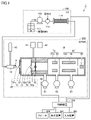
- FIG. 1 is a diagram showing a configuration example of an analysis system of the present disclosure.
- FIG. 1 shows an LC-ICPMS (Liquid Chromatograph-Inductively Coupled Plasma Mass Spectrometry) 1000 as an example of an analysis system.
- the LC-ICPMS 1 performs arsenic (As)-specific analysis for samples containing arsenic (As).
- LC-ICPMS1 includes a liquid chromatograph (hereinafter also referred to as "LC100"), an ICP mass spectrometer (hereinafter also referred to as "ICPMS200”), a control device 300, an input device 400, A display device 500 and a speaker 600 are provided.
- the ICPMS 200 corresponds to the "mass spectrometer" of the present disclosure. In this embodiment, an example in which the ICPMS 200 is connected to the LC 100 will be described, but it may be connected to another device.
- LC 100 includes mobile phase container 111 , liquid transfer pump 112 , injector 113 and column 114 .
- the mobile phase M of the sample S is accommodated in the mobile phase container 111 .
- the mobile phase M of the present embodiment is a solvent containing phosphoric acid.
- the mobile phase M is ammonium phosphate.
- the liquid feed pump 112 sucks the mobile phase M from the mobile phase container 111 and feeds it to the injector 113 .
- the injector 113 injects the sample S introduced by the user into the mobile phase M.
- Column 114 separates a plurality of components in sample S in the time direction. Separated sample S and mobile phase M are transported to ICPMS 200 .
- the ICPMS 200 includes a plasma torch 10 , a sampling section 20 arranged in front of the plasma torch 10 , and a mass analysis section 30 arranged adjacent to the sampling section 20 .
- Plasma torch 10 corresponds to the "plasma ion source" of the present disclosure.
- the plasma torch 10 ionizes the separated sample S and mobile phase M.
- it includes a sample tube, a plasma gas tube, and a cooling gas tube.
- a sample S and a mobile phase M (hereinafter also referred to as “object”) conveyed from the LC 100 are introduced into the plasma torch 10 .
- a plasma gas tube is formed around the outer circumference of the sample tube.
- the cooling gas pipe is formed around the outer periphery of the plasma gas pipe.
- the sample tube is connected to a nebulizing gas supply source for supplying nebulizing gas.
- a plasma gas supply source that supplies plasma gas eg, argon gas
- a cooling gas supply source for supplying cooling gas is connected to the cooling gas pipe.
- the sampling unit 20 has an aluminum and copper block housing 21 with through holes. A space inside the housing 21 serves as a storage chamber 25 .
- a sampling cone 51, a skimmer cone 52, and an extractor electrode 53 are arranged in order from the plasma torch 10 side.
- a cooling solvent flow path (not shown) for circulating cooling water is formed in the wall of the housing 21, and the cooling solvent supply source 41 and the inlet/outlet of the cooling solvent flow path are connected. Thereby, the housing 21 is cooled by cooling water.
- An opening 22 is formed in the wall of the housing 21 and connected to the first vacuum pump 61 .
- the storage chamber 25 is evacuated to a lower pressure than the atmospheric pressure by the first vacuum pump 61 . Therefore, the ionized sample S and mobile phase M are introduced into the storage chamber 25 by being drawn into the storage chamber 25 .
- the accommodation chamber 25 has a function of outputting ions supplied from the plasma torch 10 to the mass spectrometer 30 .
- the first vacuum pump 61 corresponds to the "vacuum pump" of the present disclosure.
- the sampling cone 51 is a metal body having a disc and a conical portion formed in the center of the disc.
- a circular opening 51a is formed in the center of the conical portion.
- the opening 51a of the sampling cone 51 has a shape that gradually widens in the ion traveling direction.
- the skimmer cone 52 is a metal body having a disk body and a conical portion formed in the center of the disk body. A circular opening 52a is formed in the center of the conical portion. The opening 52a of the skimmer cone 52 is shaped such that it gradually widens in the ion traveling direction.
- the extractor electrode 53 is a metal body having a disc and a cylindrical portion 53a formed in the center of the disc. A voltage of a predetermined value is applied to the extractor electrode 53 from the power supply device 42 .
- the power supply device 42 also supplies power to other parts. The power supply device 42 supplies power to, for example, the first vacuum pump 61 and the like.
- the mass spectrometer 30 includes a first chamber 31 and a second chamber 32.
- the first chamber 31 has an aluminum case-shaped housing 31a.
- An ion lens unit 33 such as a converging lens is arranged in the housing 31a.
- a second vacuum pump 62 is connected to the first chamber 31 .
- the first chamber 31 is evacuated by the second vacuum pump 62 .
- the second chamber 32 has an aluminum case-shaped housing 32a.
- a mass separator 34 and a detector 35 are arranged in the housing 32a.
- the mass separator 34 is configured with a quadrupole rod structure or the like.
- the detector 35 is composed of an electromultiplier or the like.
- a detection result by the detector 35 is output to the control device 300 .
- the control device 300 causes the display device 500 to display information corresponding to the detection result.
- a third vacuum pump 63 is connected to the second chamber 32 .
- the second chamber 32 is evacuated by the third vacuum pump 63 .
- the first vacuum pump 61, the second vacuum pump 62, and the third vacuum pump 63 may be any pumps as long as they can evacuate the corresponding spaces.
- the first vacuum pump 61, the second vacuum pump 62, and the third vacuum pump 63 are, for example, rotary vane pumps.
- plasma P is generated by supplying a high frequency current to the high frequency induction coil of the plasma torch 10.
- the sample S is ionized by the heat of the plasma P at 5000 to 6000 degrees.
- the ions and plasma P pass through the opening 51 a of the sampling cone 51 and are introduced into the housing 21 .
- the ions introduced into the housing 21 sequentially pass through the opening 52a of the skimmer cone 52 and the cylindrical portion 53a of the extractor electrode 53 and are introduced into the housing 31a.
- the ion lens section 33 converges the ions from the sampling section 20 toward the second chamber 32 .
- a voltage obtained by superimposing a DC voltage and a high-frequency voltage is applied to the mass separation section 34 .
- Only ions having a mass number (mass m/charge z) corresponding to the applied voltage selectively pass through the mass separator 34 .
- the selected ions thus reach the detector 35 .
- the mass number of ions passing through the second chamber 32 depends on the applied voltage. Therefore, by manipulating the voltage by a user or the like, an ion intensity signal for ions having a predetermined mass number can be obtained at the detector 35 .
- the control device 300 controls the LC 100, the ICPMS 200, and the like.
- the input device 400 accepts input of commands from the user.
- the input device 400 is composed of, for example, a keyboard and a mouse.
- the display device 500 displays various information under the control of the control device 300 .
- the input device 400 and the display device 500 may be integrated to function as a touch panel.
- the speaker 600 outputs various sounds under the control of the control device 300 .
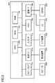
- FIG. 2 is a diagram showing a hardware configuration example of the control device 300.
- control device 300 includes, as main components, a CPU (Central Processing Unit) 160, a ROM (Read Only Memory) 162, a RAM (Random Access Memory) 164, and an HDD (Hard Disk Drive). 166, a communication I/F (Interface) 168, a display I/F 170, an input I/F 172, and a speaker I/F 174. Each component is interconnected by a data bus.
- a CPU Central Processing Unit
- ROM Read Only Memory
- RAM Random Access Memory
- HDD Hard Disk Drive
- the communication I/F 168 is an interface for communicating with the LC 100 and ICPMS 200.
- Display I/F 170 is an interface for communicating with display device 500 .
- Input I/F 172 is an interface for communicating with input device 400 .
- Speaker I/F 174 is an interface for communicating with speaker 600 .
- the ROM 162 stores programs executed by the CPU 160 .
- RAM 164 can temporarily store data generated by execution of programs in CPU 160 and data input via communication I/F 168 .
- RAM 164 may function as a temporary data memory used as a work area.
- HDD 166 is a non-volatile storage device. A semiconductor storage device such as a flash memory may be employed instead of the HDD 166 .
- the program stored in the ROM 162 may be stored in a recording medium and distributed as a program product. Alternatively, the program may be provided by an information provider as a downloadable product program via the so-called Internet.
- Control device 300 reads a program provided by a recording medium or the Internet. Control device 300 stores the read program in a predetermined storage area (for example, ROM 162). CPU 160 can execute various processes by executing the program.
- the recording medium may be a medium such as DVD-ROM (Digital Versatile-Disk Read Only Memory), CD-ROM (compact disc read-only memory), etc. that permanently carries the program. Also, the recording medium is a computer-readable non-transitory medium for programs and the like.
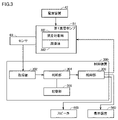
- FIG. 3 is a functional block diagram of the control device 300 and the like.
- the control device 300 includes an acquisition unit 302 , a determination unit 304 , a control unit 306 and a storage unit 308 .
- the first vacuum pump 61 also includes a lubricating object 381 and lubricating oil 382 .
- the object to be lubricated 381 is driven by receiving power from the power supply device 42 .
- the lubricating object 381 is a portion that is driven to perform the exhaust process by the first vacuum pump 61 .
- a lubrication object 381 is a portion lubricated with lubricating oil 382 .
- the lubricating objects 381 are bearings including a rotor, vanes, and the like. Lubricating oils are also inexpensive mineral or synthetic oils.
- the sensor 60 detects the current value flowing through the first vacuum pump 61 as the current value consumed by the first vacuum pump 61 (hereinafter also referred to as current consumption value I).
- Sensor 60 is, for example, an ammeter (current measuring device) that detects the current value supplied to first vacuum pump 61 .
- Sensor 60 outputs the detected current consumption value I to control device 300 .
- Acquisition unit 302 of control device 300 acquires current consumption value I.
- FIG. Acquisition unit 302 outputs current consumption value I to determination unit 304 .
- the ammonium phosphate solution as the mobile phase M is introduced from the LC 100 into the ICPMS 200 into the storage chamber 25 .
- the ammonium phosphate solution generates gas containing water vapor (hereinafter also referred to as "corrosive gas") by the plasma P of the ICPMS 200 .
- the first vacuum pump 61 evacuates the storage chamber 25 , so the corrosive gas is discharged to the outside via the first vacuum pump 61 .
- the corrosive gas passes through the first vacuum pump 61, the lubricating oil 382 inside the first vacuum pump 61 is deteriorated by this corrosive gas.
- the viscosity of the lubricating oil 382 increases.
- the rotation resistance of the rotor of the first vacuum pump 61 increases.
- the first Failure to start the vacuum pump 61 may occur.
- the surface temperature of the first vacuum pump 61 increases due to self-heating of the first vacuum pump 61 (the surface temperature reaches, for example, nearly 50 degrees). Therefore, the increase in viscosity of the lubricating oil is reduced, and the evacuation of the first vacuum pump 61 is not affected.
- the cooling of the first vacuum pump 61 causes the viscosity of the lubricating oil 382 to significantly increase, and the rotor is damaged. Rotational resistance increases, and the above-described start failure may occur.
- manufacturers of the ICPMS 200 recommend replacing the lubricating oil 382 at predetermined intervals (for example, every 6 months). However, the user is not always able to replace it at the appropriate time. Therefore, ICPMS 200 may be used even though lubricating oil 382 is degraded. In this case, the start failure described above may occur. In addition, the lubricating oil 382 may be replaced even though the lubricating oil 382 has not deteriorated. In this case, the lubricating oil 382 is wasted.
- a first configuration is conceivable in which PFPE oil (perfluoropolyether: fomblin), which is a fluorine-based oil, is used as the lubricating oil 382.
- PFPE oil perfluoropolyether: fomblin
- a dry pump that does not use lubricating oil is used as the first vacuum pump 61 .
- the first and second configurations have the problem of increasing the cost of the ICPMS 200 .
- the sensor 60 detects the current consumption value I in the first vacuum pump 61 (the current consumption value in the motor of the first vacuum pump 61), and the acquisition unit 302 obtains the current consumption value I. get.
- a determination unit 304 determines whether or not the consumption current value I is equal to or greater than a predetermined threshold value Th.
- the threshold Th is stored in the storage unit 308 . Also, the determination unit 304 outputs the determination result to the control unit 306 .
- the control unit 306 When the consumption current value I is equal to or greater than the predetermined threshold value Th, it means that the rotation resistance of the rotor of the first vacuum pump 61 is increasing, that is, it is highly likely that the lubricating oil 382 has deteriorated. is the case.
- the control unit 306 notifies the user of the predetermined information.
- the predetermined information is information regarding the lubricating oil 382 of the first vacuum pump 61 . Therefore, by notifying the user of the predetermined information, it is possible to prompt the user to replace the lubricating oil 382 . Further, the control unit 306 may stop driving the first vacuum pump 61 when the current consumption value I is equal to or greater than a predetermined threshold value Th.
- the control device 300 can prevent "the first vacuum pump 61 from being driven while the rotational resistance of the rotor of the first vacuum pump 61 is increasing". Safety can be guaranteed.
- the control unit 306 may stop driving the LC-ICPMS 1 by stopping driving the first vacuum pump 61 . Further, the control unit 306 may cause the speaker 600 to output a sound prompting replacement of the lubricating oil 382 .
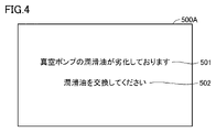
- FIG. 4 is a diagram showing an example of the predetermined information.
- the predetermined information is displayed in display area 500A of display device 500 .
- the predetermined information includes first information 501 and second information 502 .
- the first information 501 is information indicating that the lubricating oil 382 of the first vacuum pump 61 has deteriorated.
- the information is information indicating the phrase "The lubricating oil of the vacuum pump has deteriorated.”
- the second information 502 is information that prompts replacement of the lubricating oil 382 of the first vacuum pump 61 .
- the second information 502 is information indicating the text "Please replace the lubricating oil".
- the display device 500 may display either the first information 501 or the second information 502 .
- Display device 500 may display an image (for example, a character image) that is different from the information shown in FIG.
- the predetermined information may be information for indirectly recognizing replacement of the lubricating oil 382 .
- FIG. 5 is an example of a flowchart of main processing in the control device 300 .
- the control device 300 starts ionizing the sample S and the mobile phase M with the plasma P.
- the control device 300 controls the first vacuum pump 61 to evacuate the storage chamber 25 by the first vacuum pump 61 . Thereby, the ionized sample S and mobile phase M are introduced into the storage chamber 25 .
- step S5 the control device 300 determines whether or not the analysis process has ended. If the analysis process has ended (YES in step S5), the process of FIG. 5 ends. If the analysis process has not ended (NO in step S5), the process proceeds to step S6.
- step S6 the control device 300 acquires the current consumption value I (corresponding to the current consumption value in the first vacuum pump 61).
- control device 300 determines whether current consumption value I is equal to or greater than threshold Th. If the consumption current value I is less than the threshold Th (NO in step S8), the process returns to step S5. The case where the consumption current value I is less than the threshold value Th means the case where the lubricating oil 382 has not deteriorated. If the current consumption value I is equal to or greater than the threshold value Th (YES in step S8), the controller 300 stops driving the first vacuum pump 61 in step S10. Next, in step S12, the control device 300 notifies predetermined information (see FIG. 4).
- the ICPMS 200 of this embodiment has the following premises.
- a sample S and a mobile phase M are ionized by a plasma torch 10 .
- a corrosive gas is generated by ionizing the mobile phase M (ammonium phosphate).
- the first vacuum pump 61 evacuates the storage chamber 25
- the corrosive gas contained in the gas passes through the first vacuum pump 61 because the gas in the storage chamber 25 is discharged to the outside.
- the corrosive gas passes through the first vacuum pump 61, the corrosive gas reacts with the lubricating oil 382, and the lubricating oil 382 deteriorates (the viscosity of the lubricating oil 382 increases).
- the ICPMS 200 can notify predetermined information about the lubricating oil 382 at an appropriate time.
- the mobile phase is ammonium phosphate
- the mobile phase may also be other substances.
- the mobile phase may also be other substances including, for example, phosphoric acid.
- the mobile phase may be a substance containing either sulfonic acid or dimethylsulfoxide.
- the LC-ICPMS 1 of the present embodiment has been described to be configured to perform morphological analysis of arsenic, that is, the sample S is a substance containing arsenic. However, the LC-ICPMS 1 may also perform morphological analysis of other substances.
- the detected value is the current consumption value I
- the detected value may be another value.
- the detected value may be, for example, the power consumption value in first vacuum pump 61 (for example, the power value supplied to first vacuum pump 61).
- the sensor 60 is a power sensor that detects the power level supplied to the first vacuum pump 61 .
- control device 300 acquires the current value detected by the sensor 60 as the current consumption value I in the first vacuum pump 61 .
- control device 300 may acquire, as current consumption value I, a value obtained by performing a predetermined calculation on the current value detected by sensor 60 .
- the control device 300 may acquire, as the current consumption value I, a value obtained by performing a predetermined calculation on the power value detected by the power sensor.
- the control device 300 obtains another parameter without using the current value detected by the sensor 60 or the power value detected by the power sensor, and performs a predetermined calculation on the other parameter to reduce the power consumption. A current value or power consumption value may be obtained. Even the LC-ICPMS 1 adopting such a configuration has the same effect as the above-described embodiment.
- a mass spectrometer includes a plasma ion source that ionizes a sample and a mobile phase of the sample, a storage chamber into which the ionized sample and mobile phase are introduced, and a vacuum in the storage chamber.
- the control device acquires a detected value that is a current consumption value of the vacuum pump or a power consumption value of the vacuum pump, and if the detected value is a threshold value or more, the vacuum pump to notify the user of predetermined information about the lubricating oil.
- the mass spectrometer of the first item it is possible to notify the user of predetermined information regarding the lubricating oil of the vacuum pump at an appropriate time. Therefore, according to the mass spectrometer, it is possible to prevent the sample from being analyzed in a state where the lubricating oil of the vacuum pump has deteriorated.
- the safety of the vacuum pump can be ensured.
- the predetermined information includes information indicating that the lubricating oil of the vacuum pump has deteriorated.
- the mass spectrometer of the third term it is possible to make the user directly aware that the lubricating oil of the vacuum pump has deteriorated.
- the predetermined information includes information prompting replacement of the lubricating oil of the vacuum pump.
- the mobile phase contains phosphoric acid, sulfonic acid, or dimethylsulfoxide.
- the sample is analyzed in a state where the lubricating oil of the vacuum pump has deteriorated. can be suppressed.
- a method comprises ionizing a sample and a mobile phase of the sample, evacuating a storage chamber into which the ionized sample and mobile phase are introduced with a vacuum pump, obtaining a detected value that is a current consumption value in the vacuum pump or a power consumption value in the vacuum pump; and notifying a user of predetermined information when the detected value is equal to or greater than a threshold.
- 10 plasma torch 20 sampling unit, 21 housing, 22 opening, 25 storage chamber, 30 mass spectrometry unit, 31 first chamber, 32 second chamber, 33 ion lens unit, 34 mass separation unit, 35 detector, 41 cooling solvent supply source, 42 power supply, 51 sampling cone, 51a opening, 52 skimmer cone, 53 extractor electrode, 60 sensor, 61 first vacuum pump, 62 second vacuum pump, 63 third vacuum pump, 111 container, 112 Liquid feed pump, 113 injector, 114 column, 162 ROM, 164 RAM, 300 control device, 302 acquisition unit, 304 determination unit, 306 control unit, 308 storage unit, 381 lubricating object, 382 lubricating oil, 400 input device, 500 Display device, 500A display area, 501 first information, 502 second information.
Landscapes
- Chemical & Material Sciences (AREA)
- Analytical Chemistry (AREA)
- Health & Medical Sciences (AREA)
- Life Sciences & Earth Sciences (AREA)
- General Health & Medical Sciences (AREA)
- Pathology (AREA)
- Engineering & Computer Science (AREA)
- Biochemistry (AREA)
- Chemical Kinetics & Catalysis (AREA)
- General Physics & Mathematics (AREA)
- Immunology (AREA)
- Physics & Mathematics (AREA)
- Electrochemistry (AREA)
- General Chemical & Material Sciences (AREA)
- Oil, Petroleum & Natural Gas (AREA)
- Food Science & Technology (AREA)
- Medicinal Chemistry (AREA)
- Other Investigation Or Analysis Of Materials By Electrical Means (AREA)
Priority Applications (2)
| Application Number | Priority Date | Filing Date | Title |
|---|---|---|---|
| JP2023520854A JP7868611B2 (ja) | 2021-05-14 | 2022-03-10 | 質量分析装置および方法 |
| CN202280034305.7A CN117425825A (zh) | 2021-05-14 | 2022-03-10 | 质量分析装置及方法 |
Applications Claiming Priority (2)
| Application Number | Priority Date | Filing Date | Title |
|---|---|---|---|
| JP2021-082219 | 2021-05-14 | ||
| JP2021082219 | 2021-05-14 |
Publications (1)
| Publication Number | Publication Date |
|---|---|
| WO2022239438A1 true WO2022239438A1 (ja) | 2022-11-17 |
Family
ID=84029169
Family Applications (1)
| Application Number | Title | Priority Date | Filing Date |
|---|---|---|---|
| PCT/JP2022/010559 Ceased WO2022239438A1 (ja) | 2021-05-14 | 2022-03-10 | 質量分析装置および方法 |
Country Status (3)
| Country | Link |
|---|---|
| JP (1) | JP7868611B2 (cg-RX-API-DMAC7.html) |
| CN (1) | CN117425825A (cg-RX-API-DMAC7.html) |
| WO (1) | WO2022239438A1 (cg-RX-API-DMAC7.html) |
Citations (5)
| Publication number | Priority date | Publication date | Assignee | Title |
|---|---|---|---|---|
| JPS63268996A (ja) * | 1987-04-24 | 1988-11-07 | Tokyo Electron Ltd | オイル回転ポンプ劣化警報装置 |
| JPH07208369A (ja) * | 1993-12-30 | 1995-08-08 | Jatco Corp | 真空ポンプの劣化監視装置 |
| JP2009503480A (ja) * | 2005-07-25 | 2009-01-29 | メタノミクス ゲーエムベーハー | クロマトグラフィー/マススペクトロメトリーを用いてサンプルを分析する手段と方法 |
| JP2015194380A (ja) * | 2014-03-31 | 2015-11-05 | 株式会社島津製作所 | サンプリング部及びそれを備えたicp質量分析装置 |
| US20210018264A1 (en) * | 2018-04-10 | 2021-01-21 | Ima Life North America Inc. | Freeze drying process and equipment health monitoring |
Family Cites Families (7)
| Publication number | Priority date | Publication date | Assignee | Title |
|---|---|---|---|---|
| JPH04129156A (ja) * | 1990-09-19 | 1992-04-30 | Hitachi Ltd | プラズマイオン源極微量元素質量分析装置 |
| JPH11258223A (ja) * | 1998-03-13 | 1999-09-24 | Shimadzu Corp | 液体クロマトグラフ質量分析装置 |
| JP2000283056A (ja) | 1999-03-26 | 2000-10-10 | Hitachi Ltd | 真空ポンプ異常監視システム |
| JP3677410B2 (ja) * | 1999-04-30 | 2005-08-03 | 株式会社日立製作所 | 液体クロマトグラフ質量分析装置 |
| JP4031380B2 (ja) | 2003-02-25 | 2008-01-09 | 住友化学株式会社 | 白金含有化合物の分析方法 |
| GB0809976D0 (en) * | 2008-06-02 | 2008-07-09 | Edwards Ltd | Vacuum pumping systems |
| US11143665B2 (en) * | 2016-09-21 | 2021-10-12 | Hitachi High-Tech Corporation | Automatic analyzer |
-
2022
- 2022-03-10 WO PCT/JP2022/010559 patent/WO2022239438A1/ja not_active Ceased
- 2022-03-10 JP JP2023520854A patent/JP7868611B2/ja active Active
- 2022-03-10 CN CN202280034305.7A patent/CN117425825A/zh active Pending
Patent Citations (5)
| Publication number | Priority date | Publication date | Assignee | Title |
|---|---|---|---|---|
| JPS63268996A (ja) * | 1987-04-24 | 1988-11-07 | Tokyo Electron Ltd | オイル回転ポンプ劣化警報装置 |
| JPH07208369A (ja) * | 1993-12-30 | 1995-08-08 | Jatco Corp | 真空ポンプの劣化監視装置 |
| JP2009503480A (ja) * | 2005-07-25 | 2009-01-29 | メタノミクス ゲーエムベーハー | クロマトグラフィー/マススペクトロメトリーを用いてサンプルを分析する手段と方法 |
| JP2015194380A (ja) * | 2014-03-31 | 2015-11-05 | 株式会社島津製作所 | サンプリング部及びそれを備えたicp質量分析装置 |
| US20210018264A1 (en) * | 2018-04-10 | 2021-01-21 | Ima Life North America Inc. | Freeze drying process and equipment health monitoring |
Also Published As
| Publication number | Publication date |
|---|---|
| JP7868611B2 (ja) | 2026-06-02 |
| JPWO2022239438A1 (cg-RX-API-DMAC7.html) | 2022-11-17 |
| CN117425825A (zh) | 2024-01-19 |
Similar Documents
| Publication | Publication Date | Title |
|---|---|---|
| US20190371584A1 (en) | Bench-top time of flight mass spectrometer | |
| JP5454416B2 (ja) | 質量分析装置 | |
| CN112243532B (zh) | 台式飞行时间质谱仪 | |
| CN106992109B (zh) | 改进离子转移管件流量和抽吸系统负载 | |
| JP5722125B2 (ja) | 質量分析装置 | |
| US9548193B2 (en) | Quadrupole mass spectrometer with quadrupole mass filter as a mass separator | |
| JPWO2020110264A1 (ja) | 質量分析装置 | |
| EP3509086A1 (en) | Elemental analysis device and elemental analysis method | |
| WO2015118681A1 (ja) | 質量分析装置及び質量分析方法 | |
| US10551346B2 (en) | Ion analysis device | |
| CN108695135A (zh) | 用于从气溶胶颗粒生成元素离子的离子源和方法 | |
| US20110073756A1 (en) | Quadrupole Mass Spectrometer | |
| JP7221037B2 (ja) | 質量分析システムにおけるインサイチュ調整 | |
| US9134274B2 (en) | Discharge ionization current detector | |
| JP7352956B2 (ja) | 質量分析システム | |
| JP5024375B2 (ja) | 質量分析装置 | |
| CN117425825A (zh) | 质量分析装置及方法 | |
| EP4322201A1 (en) | Mass spectrometer and method for controlling same | |
| JP2008053020A (ja) | 質量分析装置 | |
| WO2018011861A1 (ja) | 分析装置 | |
| US20240177980A1 (en) | Mass spectrometer and mass spectrometry method | |
| CN112189250B (zh) | 台式飞行时间质谱仪 | |
| CN102324377B (zh) | 四极型质量分析装置 | |
| JP3928562B2 (ja) | ガスクロマトグラフ質量分析装置 | |
| US20250372361A1 (en) | Varying Turbo Pump Speed to Optimize Pressure Levels within a Mass Spectrometer |
Legal Events
| Date | Code | Title | Description |
|---|---|---|---|
| 121 | Ep: the epo has been informed by wipo that ep was designated in this application |
Ref document number: 22807145 Country of ref document: EP Kind code of ref document: A1 |
|
| WWE | Wipo information: entry into national phase |
Ref document number: 2023520854 Country of ref document: JP |
|
| WWE | Wipo information: entry into national phase |
Ref document number: 202280034305.7 Country of ref document: CN |
|
| NENP | Non-entry into the national phase |
Ref country code: DE |
|
| 122 | Ep: pct application non-entry in european phase |
Ref document number: 22807145 Country of ref document: EP Kind code of ref document: A1 |