WO2022239352A2 - 固体電解質、固体電解質の製造方法、および電池 - Google Patents
固体電解質、固体電解質の製造方法、および電池 Download PDFInfo
- Publication number
- WO2022239352A2 WO2022239352A2 PCT/JP2022/006556 JP2022006556W WO2022239352A2 WO 2022239352 A2 WO2022239352 A2 WO 2022239352A2 JP 2022006556 W JP2022006556 W JP 2022006556W WO 2022239352 A2 WO2022239352 A2 WO 2022239352A2
- Authority
- WO
- WIPO (PCT)
- Prior art keywords
- solid electrolyte
- halide
- content ratio
- atoms
- mass
- Prior art date
- Legal status (The legal status is an assumption and is not a legal conclusion. Google has not performed a legal analysis and makes no representation as to the accuracy of the status listed.)
- Ceased
Links
Images

Classifications
-
- H—ELECTRICITY
- H01—ELECTRIC ELEMENTS
- H01M—PROCESSES OR MEANS, e.g. BATTERIES, FOR THE DIRECT CONVERSION OF CHEMICAL ENERGY INTO ELECTRICAL ENERGY
- H01M10/00—Secondary cells; Manufacture thereof
- H01M10/05—Accumulators with non-aqueous electrolyte
- H01M10/056—Accumulators with non-aqueous electrolyte characterised by the materials used as electrolytes, e.g. mixed inorganic/organic electrolytes
- H01M10/0561—Accumulators with non-aqueous electrolyte characterised by the materials used as electrolytes, e.g. mixed inorganic/organic electrolytes the electrolyte being constituted of inorganic materials only
- H01M10/0562—Solid materials
-
- C—CHEMISTRY; METALLURGY
- C01—INORGANIC CHEMISTRY
- C01F—COMPOUNDS OF THE METALS BERYLLIUM, MAGNESIUM, ALUMINIUM, CALCIUM, STRONTIUM, BARIUM, RADIUM, THORIUM, OR OF THE RARE-EARTH METALS
- C01F17/00—Compounds of rare earth metals
- C01F17/10—Preparation or treatment, e.g. separation or purification
-
- C—CHEMISTRY; METALLURGY
- C01—INORGANIC CHEMISTRY
- C01F—COMPOUNDS OF THE METALS BERYLLIUM, MAGNESIUM, ALUMINIUM, CALCIUM, STRONTIUM, BARIUM, RADIUM, THORIUM, OR OF THE RARE-EARTH METALS
- C01F17/00—Compounds of rare earth metals
- C01F17/30—Compounds containing rare earth metals and at least one element other than a rare earth metal, oxygen or hydrogen, e.g. La4S3Br6
- C01F17/36—Compounds containing rare earth metals and at least one element other than a rare earth metal, oxygen or hydrogen, e.g. La4S3Br6 halogen being the only anion, e.g. NaYF4
-
- H—ELECTRICITY
- H01—ELECTRIC ELEMENTS
- H01B—CABLES; CONDUCTORS; INSULATORS; SELECTION OF MATERIALS FOR THEIR CONDUCTIVE, INSULATING OR DIELECTRIC PROPERTIES
- H01B1/00—Conductors or conductive bodies characterised by the conductive materials; Selection of materials as conductors
- H01B1/06—Conductors or conductive bodies characterised by the conductive materials; Selection of materials as conductors mainly consisting of other non-metallic substances
-
- H—ELECTRICITY
- H01—ELECTRIC ELEMENTS
- H01B—CABLES; CONDUCTORS; INSULATORS; SELECTION OF MATERIALS FOR THEIR CONDUCTIVE, INSULATING OR DIELECTRIC PROPERTIES
- H01B13/00—Apparatus or processes specially adapted for manufacturing conductors or cables
-
- H—ELECTRICITY
- H01—ELECTRIC ELEMENTS
- H01M—PROCESSES OR MEANS, e.g. BATTERIES, FOR THE DIRECT CONVERSION OF CHEMICAL ENERGY INTO ELECTRICAL ENERGY
- H01M10/00—Secondary cells; Manufacture thereof
- H01M10/05—Accumulators with non-aqueous electrolyte
-
- H—ELECTRICITY
- H01—ELECTRIC ELEMENTS
- H01M—PROCESSES OR MEANS, e.g. BATTERIES, FOR THE DIRECT CONVERSION OF CHEMICAL ENERGY INTO ELECTRICAL ENERGY
- H01M10/00—Secondary cells; Manufacture thereof
- H01M10/05—Accumulators with non-aqueous electrolyte
- H01M10/052—Li-accumulators
-
- C—CHEMISTRY; METALLURGY
- C01—INORGANIC CHEMISTRY
- C01P—INDEXING SCHEME RELATING TO STRUCTURAL AND PHYSICAL ASPECTS OF SOLID INORGANIC COMPOUNDS
- C01P2006/00—Physical properties of inorganic compounds
- C01P2006/40—Electric properties
-
- H—ELECTRICITY
- H01—ELECTRIC ELEMENTS
- H01M—PROCESSES OR MEANS, e.g. BATTERIES, FOR THE DIRECT CONVERSION OF CHEMICAL ENERGY INTO ELECTRICAL ENERGY
- H01M2300/00—Electrolytes
- H01M2300/0017—Non-aqueous electrolytes
- H01M2300/0065—Solid electrolytes
- H01M2300/0068—Solid electrolytes inorganic
- H01M2300/008—Halides
-
- Y—GENERAL TAGGING OF NEW TECHNOLOGICAL DEVELOPMENTS; GENERAL TAGGING OF CROSS-SECTIONAL TECHNOLOGIES SPANNING OVER SEVERAL SECTIONS OF THE IPC; TECHNICAL SUBJECTS COVERED BY FORMER USPC CROSS-REFERENCE ART COLLECTIONS [XRACs] AND DIGESTS
- Y02—TECHNOLOGIES OR APPLICATIONS FOR MITIGATION OR ADAPTATION AGAINST CLIMATE CHANGE
- Y02E—REDUCTION OF GREENHOUSE GAS [GHG] EMISSIONS, RELATED TO ENERGY GENERATION, TRANSMISSION OR DISTRIBUTION
- Y02E60/00—Enabling technologies; Technologies with a potential or indirect contribution to GHG emissions mitigation
- Y02E60/10—Energy storage using batteries
Definitions
- the present disclosure relates to solid electrolytes, solid electrolyte manufacturing methods, and batteries.
- Patent Document 1 discloses a method for producing a halide that includes a firing step.
- An object of the present disclosure is to provide a solid electrolyte suitable for improving ionic conductivity.
- a solid electrolyte comprising Li, M, and X
- the M is at least one selected from the group consisting of metal elements other than Li and metalloid elements
- X is at least one selected from the group consisting of F, Cl, Br, and I
- the coefficient of variation of the content ratio of M and X in the solid electrolyte is obtained by the following method: For the solid electrolyte, the average value AM and standard deviation ⁇ M of the content ratio of M , and the average value AX and standard deviation ⁇ X of the content ratio of X are obtained.
- the coefficient of variation of the content ratio of M is obtained using the average value AM and standard deviation ⁇ M of M
- the content ratio of X is calculated using the average value AX and standard deviation ⁇ X of the content ratio of X. Calculate the coefficient of variation.
- the present disclosure provides a solid electrolyte suitable for improving ionic conductivity.
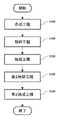
- FIG. 1 is a flow chart showing a method for producing a solid electrolyte according to the second embodiment.
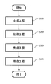
- FIG. 2 is a flow chart showing a method for manufacturing a solid electrolyte according to the third embodiment.
- FIG. 3 is a flow chart showing a method for manufacturing a solid electrolyte according to the fourth embodiment.
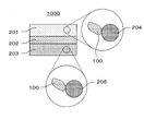
- FIG. 4 shows a cross-sectional view of a battery 1000 according to a fifth embodiment.
- the solid electrolyte according to the first embodiment contains Li, M, and X.
- M is at least one selected from the group consisting of metal elements other than Li and metalloid elements.
- X is at least one selected from the group consisting of F, Cl, Br and I;
- the coefficient of variation of the content of M is 10 or less, and the coefficient of variation of the content of X is 15 or less.
- the coefficient of variation of the content ratios of M and X in the solid electrolyte according to the first embodiment is obtained by the following method: For the solid electrolyte, an average value A M and a standard deviation ⁇ M of the content ratio of M, and an average value A X and a standard deviation ⁇ X of the content ratio of X are obtained.
- the coefficient of variation of the content ratio of M is obtained using the average value AM and standard deviation ⁇ M of M
- the coefficient of variation of the content ratio of X is obtained using the average value A X and standard deviation ⁇ X of the content ratio of X .
- the coefficient of variation of the content of M is obtained by ⁇ M /AM
- the coefficient of variation of the content of X is obtained by ⁇ X /A X .
- the coefficient of variation of the content of M is the coefficient of variation of the total of elements contained as M in the solid electrolyte according to the first embodiment. That is, the content ratio of M in the solid electrolyte, the average value A M of the content ratio of M, and the standard deviation ⁇ M of the content ratio of M are the total content ratio of the elements contained as M in the solid electrolyte, Mean and standard deviation.
- the coefficient of variation of the content ratio of X which is the halogen elements (F, Cl, Br, and I)
- the coefficient of variation of the total halogen elements contained in the solid electrolyte according to the first embodiment is the coefficient of variation of the total halogen elements contained in the solid electrolyte according to the first embodiment. That is, the content ratio of X in the solid electrolyte, the average value A X of the content ratio of X, and the standard deviation ⁇ X of the content ratio of X are the content ratio of the total halogen elements contained in the solid electrolyte and the average value of the content ratio. , and the standard deviation.
- the content ratio of M and X atoms in the solid electrolyte according to the first embodiment can be obtained by setting arbitrary 20 spots with a spot diameter of 1 ⁇ m and using an electron probe microanalyzer (EPMA) for each spot, for example. good.
- EPMA electron probe microanalyzer
- the solid electrolyte according to the first embodiment is a solid electrolyte containing halogen element X.
- a solid electrolyte containing a halogen element may be referred to as a halide solid electrolyte.
- the solid electrolyte according to the first embodiment is a halide solid electrolyte in which the coefficient of variation of the contents of M and X is reduced to the above range. That is, the solid electrolyte according to the first embodiment is a homogeneous halide solid electrolyte in which composition fluctuation is suppressed. Therefore, the solid electrolyte according to the first embodiment may have improved ionic conductivity.
- the coefficient of variation of the content of M may be, for example, 5 or less, or 4 or less.
- the average content of O atoms with respect to the total of all atoms excluding Li atoms may be 2.5 atomic % or less, or 2.0 atomic % or less. may be 1.5 atomic % or less, or 1.0 atomic % or less.
- the coefficient of variation of the content of M may be smaller than the coefficient of variation of the content of X.
- Elements contained as M have a great influence on the characteristics and properties of the solid electrolyte. Therefore, by suppressing fluctuations in the content of M, a solid electrolyte more suitable for improving ion conductivity can be obtained.
- the average content ratio of O atoms to the total of all atoms excluding Li atoms can be obtained, for example, by the following method: Arbitrary 20 spots with a spot diameter of 1 ⁇ m are set for the solid electrolyte, and the content ratio of O atoms to the total of all atoms excluding Li atoms is determined for each spot by EPMA. Next, the average value of the content ratio of O atoms is obtained from the result of the content ratio of O atoms in the 20 spots.
- the solid electrolyte according to the first embodiment can have more improved ionic conductivity.
- the content of M atoms determined by EPMA may satisfy the following formula (1).
- a M and ⁇ M are the above-described average value and standard deviation of the content ratio of M, respectively.
- the solid electrolyte according to the first embodiment can suppress the occurrence of discoloration by satisfying the above formula (1).
- the content ratio of X atoms determined by EPMA may satisfy the following formula (2).
- a X and ⁇ X are the above-mentioned average value and standard deviation of the content ratio of X, respectively.
- the solid electrolyte according to the first embodiment can suppress the occurrence of discoloration by satisfying the above formula (2).
- Patent Document 1 discloses a method for producing a halide including a calcination step. For example, in order to synthesize Li 3 YCl 6 , a mixed material obtained by synthesizing LiCl and YCl 3 as raw materials is fired in an inert atmosphere. In such a manufacturing method, the composition in the material becomes non-uniform, and there are cases where high ionic conductivity cannot be obtained.
- the present inventors have found that the halide solid electrolyte produced by the conventional method as described above has fluctuations (that is, variations) around the desired composition of each component constituting the halide solid electrolyte, and is completely We focused on the fact that it is not a homogenous body. We thought that by suppressing such compositional fluctuations, we could improve the ionic conductivity and also suppress the formation of undesired precipitation phases, and we investigated a method of suppressing the compositional fluctuations of the solid electrolyte. This has led the inventors to arrive at the manufacturing method of the present disclosure, such as the manufacturing method according to the second embodiment below.
- the production method of the present disclosure is a production method capable of suppressing compositional fluctuations at the microstructure level, and can produce a homogenized solid electrolyte with a composition exhibiting high ionic conductivity.
- a method for producing a solid electrolyte according to the second embodiment includes: (A) synthesizing a halide containing Li, M, and X; (B) pulverizing the halide; (C) calcining the halide.
- M is at least one selected from the group consisting of metal elements other than Li and metalloid elements;
- X is at least one selected from the group consisting of F, Cl, Br, and I; The above (A), the above (B), and the above (C) are performed in this order.
- a halide solid electrolyte is obtained.
- the above (B) pulverization and the above (C) firing are further performed on the halide.
- a halide solid electrolyte in which composition fluctuation is suppressed for example, a halide solid in which the coefficient of variation of the content ratio of M and X is reduced, such as the halide solid electrolyte according to the first embodiment
- An electrolyte is obtained.
- composition fluctuation is suppressed, and a homogeneous halide solid electrolyte can be obtained. Therefore, the halide solid electrolyte obtained by the manufacturing method according to the second embodiment can have improved ionic conductivity.
- FIG. 1 is a flow chart showing a method for producing a solid electrolyte according to the second embodiment.
- the manufacturing method according to the second embodiment includes synthesis step S100, pulverization step S200, and firing step S300.
- Synthesis step S100 a halide containing Li, M, and X is synthesized.
- starting materials that are sources of halides are mixed and the starting materials are allowed to react with each other.
- the method of synthesizing a halide by reacting starting materials may be heat treatment (eg, calcination).
- the starting materials may be reacted mechanochemically (ie, using the method of mechanochemical milling).
- the halides may be synthesized by impaction processes such as milling processes using planetary ball mills or ball mills using common pot mills. According to these methods, homogeneous halides can be synthesized.
- starting materials are LiX, M-containing oxides, or ammonium compounds.
- LiX is, for example, LiCl, LiBr, or LiI.
- An ammonium compound is, for example, NH4X .
- NH4X is, for example, NH4Cl .
- An oxide containing M is, for example, Y 2 O 3 .
- Halide precursor compounds may be used as starting materials.
- M may include Y.
- M may be Y. This causes the halides to have high ionic conductivity.
- X may contain at least one selected from the group consisting of Cl and Br. This causes the halides to have high ionic conductivity.
- a halide consisting only of Li, M, and X may be synthesized.
- Such halides can have high ionic conductivity.
- the starting material may be powder.
- the average particle size of the starting raw material powder may be, for example, 0.5 ⁇ m or more and 10 ⁇ m or less.
- the starting materials should be able to be uniformly mixed to synthesize a halide.
- the halide obtained in the synthesis step S100 is, for example, a melted body, a sintered body, or a block-shaped mass in which powder is adhered.
- a mixed material eg, mixed powder
- a heat-resistant container made of alumina that is, a sagger
- a firing furnace is placed in an inert gas atmosphere.
- inert atmospheres are argon or nitrogen.
- firing may be performed in an atmospheric furnace at 300° C. or higher and 600° C. or lower for 1 hour or longer and 20 hours or shorter while nitrogen is flowed into the furnace during the firing process and reaction gas is discharged.
- Reactive gases include, for example, moisture, chlorine, ammonium, hydrogen chloride, and the like.
- the inert gas By introducing the inert gas into the firing furnace and discharging it in this way, it is possible to prevent unnecessary reaction gas components and the like from remaining in the furnace, that is, in the halide after the reaction.
- the inert gas does not directly hit the sagger containing the starting material.
- a plate larger than the gas inlet may be placed between the gas inlet and the sheath.
- the plate may have any thickness as long as it does not break due to gas flow or handling.
- a plate such as an alumina plate is partially shielded.
- the gas comes into contact with the sheath after going around the shield plate.
- the gas inlet should be installed on the bottom side of the furnace, and the exhaust port should be installed on the upper side (for example, the ceiling side or the upper side of the side wall).
- the reaction gas can be smoothly discharged out of the furnace along with the convective flow in the furnace from bottom to top. Therefore, unnecessary residual components can be reduced.
- the introduced gas may be heated before being introduced into the furnace. Thereby, it is possible to prevent the temperature distribution in the sheath from becoming non-uniform. As a result, the reaction profile of the starting material can be homogenized, resulting in a more homogeneous halide.
- the firing temperature should be a temperature at which halides are generated. When fired at a temperature equal to or higher than the melting point of the halide, the melted state promotes diffusion of the composition more than the solid due to its fluidity, and a homogeneous block can be obtained.
- the firing temperature may be 350°C or higher and 600°C or lower.
- the firing time may be 1 hour or more and 20 hours or less.
- the temperature, time, and reaction gas discharge time required for synthesis can be determined as appropriate.
- a firing furnace with a known atmosphere can be used.
- Vacuum replacement may be performed repeatedly.
- the pods Prior to firing, the pods may be previously heat-treated with an inert gas in the same manner as in firing to remove adsorbed oxygen and moisture on the pods. Thereby, a halide can be stably synthesized.
- the temperature distribution in the sagger may be within the temperature distribution width of a commonly used firing furnace, for example, 30°C.
- the temperature distribution within the pod is the difference between the maximum temperature and the minimum temperature within the pod.
- a heat-resistant, impermeable, dense alumina container is suitable for the sagger used.
- a grade of SSA-H purity 95%, density 3.9 g/cm 3 , water absorption 0.5% or less
- SSA-H purity 95%, density 3.9 g/cm 3 , water absorption 0.5% or less
- Such grade saggers also have a high thermal conductivity of about 20 W/m ⁇ k. Therefore, non-uniform temperature distribution in the sheath is suppressed.
- the material of the sheath is not limited to alumina.
- a refractory material having a high thermal conductivity equal to or higher than that of alumina and hardly reacting with halides may be used.
- Other examples of saggers are SSA-S, SSA-T, or SSA-995 grades of alumina, or high thermal conductivity refractories such as SiC, which has a thermal conductivity of about 17 W/m ⁇ k. From the viewpoint of improving the temperature distribution and followability in temperature rising and cooling processes, it is desirable that the heat capacity of the sagger is small. For example, it is desirable that the pod be lighter than the mass of the halide being synthesized.
- the starting materials may be mechanochemically reacted.
- the starting material is placed in a planetary ball mill or pot mill together with grinding media such as zirconia balls, and ground. Repetition of the impact action from the grinding media advances the reaction and synthesizes the halide. Since the synthesis is performed in a closed space, there is no evaporation of the composition, and all the raw materials stored can be recovered, so it is easy to obtain the preparation composition.
- the well-known partially stabilized zirconia which has excellent abrasion resistance, is suitable for the grinding media.
- the inner walls of the ball mill may also be made of the same material as the hard grinding media, such as zirconia, to enhance grindability (eg, synthetic rate).
- the shape of the inner wall of the ball mill may be a cylinder or a polygonal tubular shape such as a rectangle. If the inner wall of the ball mill is polygonal cylindrical, the grindability is enhanced and the synthesis rate is accelerated.
- the grinding media are put into the mill container so that the volume ratio of the mill container is 10 to 60%, the mill container is sealed with an inert gas, and the mill container is rotated to stir.
- spherical grinding media with a diameter of 2 mm or more and 30 mm or less may be used.
- the size of the grinding media may be selected to adjust grindability (eg, synthesis rate).
- the synthesis time may be, for example, 1 hour or more and 80 hours or less. Generally, the synthesis time is 10 to 20 hours. In mass production, pulverization conditions may be set in consideration of mass productivity.
- the ball mill may be heated from the outside to activate the reaction. Thereby, mass productivity can be improved.
- synthesis proceeds only with the shear stress of the mortar and pestle.
- the synthesis may be performed by an automatic mortar (eg, a grinder) or by hand.
- the synthesis state may be stabilized by heating the mortar for accelerated synthesis or controlling the reaction temperature.
- a mortar can be placed on a hot plate to perform the mixing operation.
- the reaction rate in the synthesis step S100 may be 90% or more when the mass reduction rate of the finally obtained solid electrolyte is 100%. That is, the ratio P1 of the reduced mass D2 in the synthesis step S100 to the reduced mass D1 from the total mass of the raw materials in the finally obtained solid electrolyte may be 90% or more.
- the reduced mass D2 in the synthesis step S100 is the difference in the mass of the halide synthesized in the synthesis step S100 from the total mass of the raw materials before synthesis in the synthesis step S100.
- the ratio P1 is obtained by (D2/D1) ⁇ 100. Thereby, 90% or more of the unwanted side-reactants can be removed in the synthesis step S100.
- the mass of the halide synthesized in the synthesis step S100 may include the mass of the raw material remaining without being synthesized.
- the halide composition variations can be diffused and more homogenized. That is, due to the mutual movement of the halides in the firing step S300, the halides having a composition deviating from the target composition are diffused to homogenize the overall composition. Therefore, a solid electrolyte having higher ionic conductivity is obtained.
- Pulverization step S200 In the pulverization step S200, the halide is pulverized.
- the pulverization step S200 is performed after the synthesis step S100.
- the pulverization step S200 is, for example, a process of coarsely pulverizing the halide mass obtained in the synthesis step S100.
- the halide may be pulverized to have an average particle size of 1 cm or more.
- a block-shaped pulverized material is obtained in which the crystal quality is not damaged by pulverization and the contamination of impurities in the pulverization process is suppressed.
- such a block-shaped pulverized product has a smaller surface area than the finely pulverized powder. Therefore, deterioration of properties due to moisture during handling or storage can be suppressed.
- These provide solid electrolytes with high ionic conductivity.
- the average particle size of the halide is obtained by observing the pulverized material with an optical microscope, with one field of view being the size of at least 100 particles of the halide. It is a value obtained from the measurement value obtained by selecting 50 particles in descending order of size and measuring the particle size.
- the halide may be coarsely pulverized into blocks having an average particle size of about 3 cm. Although fine particles of 1 cm or less are generated due to chipping during coarse pulverization, it is preferable that fine pulverization processing is not performed.
- the fine pulverization process is, for example, a fine pulverization process using so-called grinding media (eg, zirconia balls). Therefore, by the pulverization step S200, a pulverized material of a large block (for example, an average particle size of 1 cm or more) of halide is obtained.
- the halide that has melted and solidified at the bottom of the pod may be crushed using a hammer or chisel.
- a coarse crusher such as a hammer crusher may be used.
- the pulverization step S200 may make most of the halide into blocks having a particle size of, for example, 1 to 3 cm.
- the pulverization process to produce finer particles often leads to reduced ionic conductivity due to damage to the crystalline quality of the surface layer of the particles due to the crushing or collision energy, as is well known. .
- the increased particle surface area due to pulverization leads to an increase in the reaction area with moisture, so the effect of a trace amount of moisture tends to become apparent, and the ionic conductivity tends to decrease. These decreases in ionic conductivity are often not recovered even by post-treatments such as annealing.
- the influence of the particle surface layer is likely to become apparent.
- the coarsely pulverized block obtained in this step can suppress not only the deterioration of the crystal quality but also the property deterioration that occurs during handling or storage between steps (for example, from the pulverization step to the firing step). Also, for example, by not performing fine pulverization, it is possible to avoid contamination with impurities from pulverizing media such as zirconia balls.
- Fine particles generated by chipping may be removed, for example, by passing through a mesh. This makes it possible to easily remove fine powder particles. By removing fine powder particles, for example by sieving, the properties of the final solid electrolyte can be improved.
- Blocks of halide obtained by coarse pulverization may be discolored (for example, black) due to deposits other than the desired halide on the surface layer side.
- unmelted impurities oxides or other compositions
- unmelted impurities may precipitate out in the form of solder sludge, floating on the molten surface in the form of a film, or reacting to gases or vaporizing during the firing process. It is a solidified foreign matter component that falls down during the cooling process. Since such foreign substances have low ionic conductivity, it is desirable to suppress their generation or remove them.
- the area exposed to the halide can be reduced and the effect of phases precipitated on the surface can be reduced.
- the ratio of the opening area (unit: cm 2 ) By setting the ratio of the opening area (unit: cm 2 ) to, for example, 0.5 or less, the influence of the precipitation phase on the surface layer can be reduced.
- the foreign matter layer By applying such a charge mass condition to the sagger to the synthesis process and the firing process, the foreign matter layer can be reduced.
- polishing may be performed not only on the surface layer but also on the contact surface with the sheath.
- baking step S300 In the firing step S300, the halide is fired.
- the baking step S300 is performed after the crushing step S200.
- the coarsely ground halide is placed in, for example, a dense alumina container.
- the directionality for example, front and back
- the difference in composition between the front and back surfaces generated in the synthesis step S100 is randomized, and further homogenization proceeds by diffusion and melting in the firing step S300.
- the sachet and the block body of the halide to be fed into the sagger are the ratio of the opening area S (unit: cm 2 ) of the container (for example, sagger) to the mass W (unit: g) of the halide, as in the firing in the synthesis step S100.
- the firing is carried out so that (S/W) becomes, for example, 0.5 or less.
- S/W elongated sagger
- 250 g of halide is charged into the above-mentioned elongated sagger (SSA-H alumina material, ⁇ 90 mm, height 150 mm).
- S/W 0.26.
- various true specific gravities of halides are approximately 2.0 to 2.5 g/cm 3 , if the firing is performed in a range where the S/W value is 0.5 or less, the foreign matter layer on the surface layer can be suppressed. can.
- Firing is performed, for example, in an inert gas atmosphere.
- the firing temperature is, for example, 300 or more and 600°C or less.
- the firing time is, for example, 1 hour or more and 20 hours or less.
- a firing furnace with a general atmosphere can be used for firing in the firing step S300.
- the inert gas is indirectly introduced into the furnace by going around from the bottom of the furnace to the upper side through the shield plate so that the gas does not directly hit the walls of the sagger. is good.
- the raw materials remaining unsynthesized in the synthesis step S100 and contained in the halide before the firing step can be homogeneously synthesized and reacted in the firing step S300. Residues solidified by cooling of components can be prevented from remaining in the solid electrolyte.
- the temperature distribution in the sagger may be, for example, within the distribution width of a general firing furnace, for example, 30°C, as described in the synthesis step S100.
- a homogeneous solid electrolyte can be obtained without using a special firing furnace or strictly controlling the firing temperature.
- Such a mass-producible process makes it possible to synthesize a halide solid electrolyte having high ionic conductivity.
- the temperature distribution in the pod for example, by placing a thermocouple at the measurement point and monitoring it through the firing process using a logger, the temperature distribution during the actual synthesis can be measured.
- the firing temperature in the firing step S300 may be higher than the firing temperature in the synthesis step S100. By heating at such a temperature, the halide is melted and the diffusibility between the blocks is improved, so that sufficient homogenization can be achieved.
- the maximum temperature of the firing process in the firing step S300 may be 5° C. or more higher than the maximum temperature of the firing process in the synthesis step S100. This facilitates remelting of the blocks obtained in the synthesis step S100, thereby promoting long-distance diffusion in the pod such as between blocks, thereby obtaining a more homogeneous halide solid electrolyte.
- the reaction rate in the firing step S300 may be 10% or less when the mass reduction rate of the finally obtained solid electrolyte is 100%. That is, the ratio P2 of the decreased mass D3 in the firing step S300 to the decreased mass D1 from the total mass of the raw materials in the finally obtained solid electrolyte may be 10% or less.
- the reduced mass D3 in the firing step S300 is the difference in the mass of the halide after firing in the firing step S300 from the mass of the halide after grinding in the grinding step S200 and before firing in the firing step S300.
- the ratio P2 is obtained by (D3/D1) ⁇ 100.
- the mass of the halide obtained in the firing step S300 may include the mass of the raw material remaining without being synthesized.
- the pods that can be used in the firing step S300 are the same as the pods described in the synthesis step S100.
- the same pods or different pods may be used in the synthesis step S100 and the firing step S300.
- the pods may be elongated in shape.
- the pods may be cylindrical.
- a radius may be provided on the inner wall of the sheath.
- Such pods are excellent in recoverability and peelability.
- the block that has been roughly ground in the grinding step S200 is placed in, for example, an elongated pod and fired, the contained halide is surrounded by the outer wall of the pod (side walls and bottom), but only the opening of the pod is exposed to the outside air. exposed to Thus, the use of the above-described pod shape preferably reduces the exposed area. As a result, it is possible to suppress the formation of a solder sludge-like film on the surface layer of the halide melt (that is, the surface exposed to the outside air).
- the solder sludge-like film that is produced is an impurity or precipitated phase that is not melted and is produced in the form of a film on the surface layer.
- the ratio of the opening area S (unit: cm 2 ) of the container to the mass W (unit: g) of the halide satisfies S/W ⁇ 0.5 (cm 2 /g). do it.
- a homogeneous halide solid electrolyte in which unnecessary precipitation phases are suppressed can be obtained.
- a dense, elongated heat-resistant container made of alumina that is impermeable to the melt is suitable.
- a sachet By using such a sachet, not only is the formation of a surface layer deposited layer suppressed, but also the molten material during cooling is exfoliated due to volumetric shrinkage, facilitating separation and recovery from the sachet.
- a halide solid electrolyte can be obtained with a recovery rate of 99% or more.
- pod shapes other than cylindrical are prismatic or gourd-shaped.
- a material such as SiC that is dense, has heat resistance, and has a small heat capacity can be used.
- FIG. 2 is a flowchart showing a solid electrolyte manufacturing method according to the third embodiment.
- the manufacturing method according to the third embodiment further includes a second crushing step S400 and a second firing step S500 in addition to the manufacturing method according to the second embodiment.
- the second pulverization step S400 is performed after the firing step S300.
- the second firing step S500 is performed after the second crushing step S400.
- a halide having a reduced coefficient of variation of the content ratio of M and X such as the halide solid electrolyte according to the first embodiment
- a solid electrolyte is obtained.
- composition fluctuation is suppressed and a homogeneous halide solid electrolyte can be obtained.
- a pulverization step and a sintering step are further performed, so that a solid electrolyte whose composition fluctuation is further suppressed can be obtained. Therefore, according to the manufacturing method according to the third embodiment, the ionic conductivity of the resulting solid electrolyte can be further increased.
- the second pulverization step S400 is a step of performing coarse pulverization, similar to the pulverization step S200.
- the second firing step S500 is a step of firing, similar to the firing step S300.
- the firing temperature in the second firing step S500 is preferably higher than the firing temperature in the firing step S300 by 5°C or more. As a result, the melted block obtained in the firing step S300 can be melted again, and homogenization can be further promoted.
- the manufacturing method according to the fourth embodiment further includes (D) polishing the halide in addition to the manufacturing method according to the second embodiment.
- (D) is described as a "polishing step”.
- FIG. 3 is a flow chart showing a method for manufacturing a solid electrolyte according to the fourth embodiment.
- the polishing step S600 is performed after the firing step S300.
- a halide having a reduced coefficient of variation of the content ratio of M and X such as the halide solid electrolyte according to the first embodiment
- a solid electrolyte is obtained.
- the manufacturing method according to the fourth embodiment as in the manufacturing method according to the second embodiment, composition fluctuation is suppressed and a homogeneous halide solid electrolyte can be obtained.
- the polishing step S600 is further performed, so it is possible to obtain a solid electrolyte in which composition fluctuation is further suppressed. Therefore, according to the manufacturing method according to the fourth embodiment, the ionic conductivity of the resulting solid electrolyte can be further increased.
- the block body of the synthesized halide solid electrolyte is polished. As a result, for example, even if a solder sludge-like impurity film or reaction residue exists on the surface layer of the block, these are removed.
- a diamond file or an iron file may be used for polishing.
- it can be used as a means for polishing treatment. Since unnecessary components can be removed by polishing, a solid electrolyte with high ionic conductivity can be obtained.
- Polishing is not limited to the surface layer of the block body, and if there is a reaction layer on the contact surface with the sheath, it may be removed for the purpose of removing it.
- the halide obtained in the synthesis step S100 may be polished. That is, the polishing step S600 may be performed between the synthesis step S100 and the pulverization step S200 instead of after the firing step S300. Alternatively, the polishing step S600 may be performed both between the synthesis step S100 and the pulverization step S200 and after the firing step S300.
- the fifth embodiment describes a battery using the solid electrolyte according to the first embodiment.
- a battery according to the fifth embodiment includes a positive electrode, a negative electrode, and an electrolyte layer.
- the electrolyte layer is provided between the positive electrode and the negative electrode.
- At least one selected from the group consisting of the positive electrode, the electrolyte layer, and the negative electrode contains the solid electrolyte according to the first embodiment.
- the battery according to the fifth embodiment contains the solid electrolyte according to the first embodiment, that is, the solid electrolyte having improved ionic conductivity, it has excellent charge-discharge characteristics.
- the battery may be an all solid state battery.
- FIG. 1 shows a cross-sectional view of a battery 1000 according to the fifth embodiment.
- a battery 1000 according to the fifth embodiment includes a positive electrode 201 , an electrolyte layer 202 and a negative electrode 203 .
- Electrolyte layer 202 is provided between positive electrode 201 and negative electrode 203 .
- the positive electrode 201 contains positive electrode active material particles 204 and solid electrolyte particles 100 .
- the electrolyte layer 202 contains an electrolyte material.
- the electrolyte material is, for example, a solid electrolyte.
- the negative electrode 203 contains negative electrode active material particles 205 and solid electrolyte particles 100 .
- the solid electrolyte particles 100 are particles containing the solid electrolyte according to the first embodiment.
- the solid electrolyte particles 100 may be particles made of the solid electrolyte according to the first embodiment, or particles containing the solid electrolyte according to the first embodiment as a main component.
- particles containing the solid electrolyte according to the first embodiment as a main component means particles in which the component contained in the largest molar ratio is the solid electrolyte according to the first embodiment.
- the solid electrolyte particles 100 may have a median diameter of 0.1 ⁇ m or more and 100 ⁇ m or less, or may have a median diameter of 0.5 ⁇ m or more and 10 ⁇ m or less. In this case, the solid electrolyte particles 100 have higher ionic conductivity.
- the positive electrode 201 contains a material that can occlude and release metal ions (eg, lithium ions).
- the material is, for example, a positive electrode active material (eg, positive electrode active material particles 204).
- positive electrode active materials are lithium-containing transition metal oxides, transition metal fluorides, polyanion materials, fluorinated polyanion materials, transition metal sulfides, transition metal oxyfluorides, transition metal oxysulfides, or transition metal oxynitrides. be.
- lithium - containing transition metal oxides are Li(Ni,Co,Al) O2 or LiCoO2.
- the notation "(A, B, C)" in the chemical formula means "at least one selected from the group consisting of A, B, and C".
- “(Ni, Co, Al)” is synonymous with “at least one selected from the group consisting of Ni, Co, and Al”.
- the positive electrode active material particles 204 may have a median diameter of 0.1 ⁇ m or more and 100 ⁇ m or less. When the positive electrode active material particles 204 have a median diameter of 0.1 ⁇ m or more, the positive electrode active material particles 204 and the solid electrolyte particles 100 are well dispersed in the positive electrode 201 . This improves the charge/discharge characteristics of the battery. When the positive electrode active material particles 204 have a median diameter of 100 ⁇ m or less, the diffusion rate of lithium in the positive electrode active material particles 204 is improved. This allows the battery to operate at high output.
- the positive electrode active material particles 204 may have a larger median diameter than the solid electrolyte particles 100 . As a result, the positive electrode active material particles 204 and the solid electrolyte particles 100 are dispersed well in the positive electrode 201 .
- the ratio of the volume of the positive electrode active material particles 204 to the sum of the volume of the positive electrode active material particles 204 and the volume of the solid electrolyte particles 100 is 0.30 or more and 0.30. It may be 95 or less.
- the positive electrode 201 may have a thickness of 10 ⁇ m or more and 500 ⁇ m or less.
- the electrolyte layer 202 contains an electrolyte material.
- the electrolyte material is, for example, the solid electrolyte according to the first embodiment.
- the electrolyte layer 202 may be a solid electrolyte layer.
- the electrolyte layer 202 may be composed only of the solid electrolyte according to the first embodiment. Alternatively, the electrolyte layer 202 may be composed only of a solid electrolyte different from the solid electrolyte according to the first embodiment.
- Examples of solid electrolytes different from the solid electrolyte according to the first embodiment are Li 2 MgX′ 4 , Li 2 FeX′ 4 , Li(Al,Ga,In)X′ 4 , Li 3 (Al,Ga,In)X ' 6 , or LiI.
- X' is at least one selected from the group consisting of F, Cl, Br and I.
- the solid electrolyte different from the solid electrolyte according to the first embodiment may be a solid electrolyte containing a halogen element, that is, a halide solid electrolyte.
- the solid electrolyte according to the first embodiment is hereinafter referred to as the first solid electrolyte.
- a solid electrolyte different from the solid electrolyte according to the first embodiment is called a second solid electrolyte.
- the electrolyte layer 202 may contain not only the first solid electrolyte but also the second solid electrolyte.
- the first solid electrolyte and the second solid electrolyte may be uniformly dispersed in the electrolyte layer 202 .
- a layer made of the first solid electrolyte and a layer made of the second solid electrolyte may be stacked along the stacking direction of the battery 1000 .
- the electrolyte layer 202 may have a thickness of 1 ⁇ m or more and 1000 ⁇ m or less. When the electrolyte layer 202 has a thickness of 1 ⁇ m or more, the short circuit between the positive electrode 201 and the negative electrode 203 is less likely to occur. If the electrolyte layer 202 has a thickness of 1000 ⁇ m or less, the battery can operate at high power.
- the negative electrode 203 contains a material capable of intercalating and deintercalating metal ions such as lithium ions.
- the material is, for example, a negative electrode active material (eg, negative electrode active material particles 205).
- Examples of negative electrode active materials are metal materials, carbon materials, oxides, nitrides, tin compounds, or silicon compounds.
- the metallic material may be a single metal or an alloy.
- Examples of metallic materials are lithium metal or lithium alloys.
- Examples of carbon materials are natural graphite, coke, ungraphitized carbon, carbon fibers, spherical carbon, artificial graphite, or amorphous carbon. From the viewpoint of capacity density, suitable examples of negative electrode active materials are silicon (ie, Si), tin (ie, Sn), silicon compounds, or tin compounds.
- the negative electrode active material particles 205 may have a median diameter of 0.1 ⁇ m or more and 100 ⁇ m or less. When the negative electrode active material particles 205 have a median diameter of 0.1 ⁇ m or more, the negative electrode active material particles 205 and the solid electrolyte particles 100 are well dispersed in the negative electrode 203 . This improves the charge/discharge characteristics of the battery. When the negative electrode active material particles 205 have a median diameter of 100 ⁇ m or less, the diffusion rate of lithium in the negative electrode active material particles 205 is improved. This allows the battery to operate at high output.
- the negative electrode active material particles 205 may have a larger median diameter than the solid electrolyte particles 100 . Thereby, in the negative electrode 203, the dispersion state of the negative electrode active material particles 205 and the solid electrolyte particles 100 is improved.
- the ratio of the volume of the negative electrode active material particles 205 to the total volume of the negative electrode active material particles 205 and the volume of the solid electrolyte particles 100 is 0.30 or more and 0.30. It may be 95 or less.
- the negative electrode 203 may have a thickness of 10 ⁇ m or more and 500 ⁇ m or less.
- At least one selected from the group consisting of positive electrode 201, electrolyte layer 202, and negative electrode 203 contains a second solid electrolyte for the purpose of enhancing ion conductivity, chemical stability, and electrochemical stability.
- the second solid electrolyte may be a halide solid electrolyte.
- halide solid electrolytes used as the second solid electrolyte are Li 2 MgX′ 4 , Li 2 FeX′ 4 , Li(Al,Ga,In)X′ 4 , Li 3 (Al,Ga,In)X′. 6 , or LiI.
- X' is at least one selected from the group consisting of F, Cl, Br and I.
- a halide solid electrolyte used as the second solid electrolyte is a compound represented by Li p Me q Y r Z 6 .
- Me is at least one element selected from the group consisting of metal elements other than Li and Y and metalloid elements.
- the value of m' represents the valence of Me.
- Z is at least one selected from the group consisting of F, Cl, Br and I; "Semimetallic elements" are B, Si, Ge, As, Sb, and Te.
- Metallic element means all elements contained in Groups 1 to 12 of the periodic table (excluding hydrogen), and all elements contained in Groups 13 to 16 of the periodic table (where B, Si, Ge, As, Sb, Te, C, N, P, O, S, and Se).
- Me is selected from the group consisting of Mg, Ca, Sr, Ba, Zn, Sc, Al, Ga, Bi, Zr, Hf, Ti, Sn, Ta, and Nb. At least one may be selected.
- the second solid electrolyte may be a sulfide solid electrolyte.
- Examples of sulfide solid electrolytes are Li 2 S—P 2 S 5 , Li 2 S—SiS 2 , Li 2 S—B 2 S 3 , Li 2 S—GeS 2 , Li 3.25 Ge 0.25 P 0 .75 S 4 , or Li 10 GeP 2 S 12 .
- the second solid electrolyte may be an oxide solid electrolyte.
- oxide solid electrolytes are (i) NASICON - type solid electrolytes such as LiTi2(PO4)3 or elemental substitutions thereof; (ii) perovskite-type solid electrolytes such as (LaLi) TiO3 , ( iii) LISICON - type solid electrolytes such as Li14ZnGe4O16 , Li4SiO4 , LiGeO4 or elemental substitutions thereof; ( iv ) garnet - type solid electrolytes such as Li7La3Zr2O12 or its elemental substitutions, or ( v) Li3PO4 or its N substitutions.
- NASICON - type solid electrolytes such as LiTi2(PO4)3 or elemental substitutions thereof
- perovskite-type solid electrolytes such as (LaLi) TiO3 ,
- LISICON - type solid electrolytes such as Li14ZnGe4O16 , Li4SiO4 , LiGeO4 or
- the second solid electrolyte may be an organic polymer solid electrolyte.
- organic polymer solid electrolytes examples include polymeric compounds and lithium salt compounds.
- the polymer compound may have an ethylene oxide structure. Since a polymer compound having an ethylene oxide structure can contain a large amount of lithium salt, the ionic conductivity can be further increased.
- lithium salts are LiPF6 , LiBF4 , LiSbF6 , LiAsF6 , LiSO3CF3, LiN(SO2CF3)2 , LiN ( SO2C2F5 ) 2 , LiN ( SO2CF3 ). ( SO2C4F9 ) , or LiC ( SO2CF3 ) 3 .
- One lithium salt selected from these may be used alone. Alternatively, a mixture of two or more lithium salts selected from these may be used.
- At least one selected from the group consisting of the positive electrode 201, the electrolyte layer 202, and the negative electrode 203 is composed of a non-aqueous electrolyte liquid, a gel electrolyte, or an ion electrolyte for the purpose of facilitating the transfer of lithium ions and improving the output characteristics of the battery. It may contain liquids.
- the non-aqueous electrolyte contains a non-aqueous solvent and a lithium salt dissolved in the non-aqueous solvent.
- non-aqueous solvents examples include cyclic carbonate solvents, chain carbonate solvents, cyclic ether solvents, chain ether solvents, cyclic ester solvents, chain ester solvents, or fluorine solvents.
- cyclic carbonate solvents are ethylene carbonate, propylene carbonate, or butylene carbonate.
- linear carbonate solvents are dimethyl carbonate, ethyl methyl carbonate, or diethyl carbonate.
- examples of cyclic ether solvents are tetrahydrofuran, 1,4-dioxane, or 1,3-dioxolane.
- linear ether solvents are 1,2-dimethoxyethane or 1,2-diethoxyethane.
- An example of a cyclic ester solvent is ⁇ -butyrolactone.
- An example of a linear ester solvent is methyl acetate.
- fluorosolvents are fluoroethylene carbonate, methyl fluoropropionate, fluorobenzene, fluoroethyl methyl carbonate, or fluorodimethylene carbonate.
- One non-aqueous solvent selected from these may be used alone. Alternatively, a mixture of two or more non-aqueous solvents selected from these may be used.
- lithium salts are LiPF6 , LiBF4 , LiSbF6 , LiAsF6 , LiSO3CF3, LiN(SO2CF3)2 , LiN ( SO2C2F5 ) 2 , LiN ( SO2CF3 ). ( SO2C4F9 ) , or LiC ( SO2CF3 ) 3 .
- One lithium salt selected from these may be used alone. Alternatively, a mixture of two or more lithium salts selected from these may be used.
- the lithium salt concentration is, for example, 0.5 mol/liter or more and 2 mol/liter or less.
- a polymer material impregnated with a non-aqueous electrolyte can be used as the gel electrolyte.
- examples of polymeric materials are polyethylene oxide, polyacrylonitrile, polyvinylidene fluoride, polymethyl methacrylate, or polymers with ethylene oxide linkages.
- ionic liquids examples include (i) aliphatic chain quaternary salts such as tetraalkylammonium or tetraalkylphosphonium; (ii) aliphatic cyclic ammoniums such as pyrrolidiniums, morpholiniums, imidazoliniums, tetrahydropyrimidiniums, piperaziniums, or piperidiniums; or (iii) nitrogen-containing heterogeneous compounds such as pyridiniums or imidazoliums It is a ring aromatic cation.
- aliphatic chain quaternary salts such as tetraalkylammonium or tetraalkylphosphonium
- aliphatic cyclic ammoniums such as pyrrolidiniums, morpholiniums, imidazoliniums, tetrahydropyrimidiniums, piperaziniums, or piperidiniums
- nitrogen-containing heterogeneous compounds
- Examples of anions contained in ionic liquids are PF 6 ⁇ , BF 4 ⁇ , SbF 6 ⁇ , AsF 6 ⁇ , SO 3 CF 3 ⁇ , N(SO 2 CF 3 ) 2 ⁇ , N(SO 2 C 2 F 5 ) 2 ⁇ , N(SO 2 CF 3 )(SO 2 C 4 F 9 ) ⁇ , or C(SO 2 CF 3 ) 3 ⁇ .
- the ionic liquid may contain a lithium salt.
- At least one selected from the group consisting of the positive electrode 201, the electrolyte layer 202, and the negative electrode 203 may contain a binder for the purpose of improving adhesion between particles.
- binders include polyvinylidene fluoride, polytetrafluoroethylene, polyethylene, polypropylene, aramid resin, polyamide, polyimide, polyamideimide, polyacrylonitrile, polyacrylic acid, polyacrylic acid methyl ester, polyacrylic acid ethyl ester, Polyacrylic acid hexyl ester, polymethacrylic acid, polymethacrylic acid methyl ester, polymethacrylic acid ethyl ester, polymethacrylic acid hexyl ester, polyvinyl acetate, polyvinylpyrrolidone, polyether, polyether sulfone, hexafluoropolypropylene, styrene-butadiene rubber , or carboxymethyl cellulose.
- Copolymers can also be used as binders.
- binders are tetrafluoroethylene, hexafluoroethylene, hexafluoropropylene, perfluoroalkyl vinyl ethers, vinylidene fluoride, chlorotrifluoroethylene, ethylene, propylene, pentafluoropropylene, fluoromethyl vinyl ether, acrylic acid , and hexadiene.
- a mixture of two or more selected from the above materials may be used as the binder.
- At least one selected from the positive electrode 201 and the negative electrode 203 may contain a conductive aid for the purpose of increasing electronic conductivity.
- Examples of conductive aids are (i) graphites such as natural or artificial graphite; (ii) carbon blacks such as acetylene black or ketjen black; (iii) conductive fibers such as carbon or metal fibers; (iv) carbon fluoride, (v) metal powders such as aluminum, (vi) conductive whiskers such as zinc oxide or potassium titanate; (vii) conductive metal oxides such as titanium oxide; or (viii) conductive polymeric compounds such as polyaniline, polypyrrole, or polythiophene.
- the conductive aid (i) or (ii) may be used.
- Examples of the shape of the battery according to the fifth embodiment are coin-shaped, cylindrical, rectangular, sheet-shaped, button-shaped, flat-shaped, and laminated.
- a material for forming a positive electrode, a material for forming an electrolyte layer, and a material for forming a negative electrode are prepared, and the positive electrode, the electrolyte layer, and the negative electrode are arranged in this order by a known method. It may also be manufactured by making laminated laminates.
- the solid electrolyte was placed in a sagger and fired, but the present invention is not limited to this.
- it may be synthesized by various firing processes such as heat treatment by spraying powder like a rotary kiln or spray drying.
- Sample 1 corresponds to a comparative example, in which neither the grinding step nor the calcination step after the synthesis step was performed.
- Sample 2 corresponds to a comparative example, in which the firing step was performed after the synthesis step without performing the pulverization step.
- Samples 3 to 19 correspond to the examples and all of the synthesis, grinding and calcination steps were performed. The synthesizing step, pulverizing step, and firing step performed in this example will be described in detail below. Table 1 shows specific conditions in each step for samples 1 to 19.
- the mixed raw materials were uniformly mixed with a pestle for about 30 minutes.
- alumina cylindrical sagger (diameter ⁇ 40 mm, height 120 mm).
- the S/W value was about 0.256.
- a spacer (thickness 5 to 10 mm) was placed on the outer edge of the upper surface of the pod so that the reaction gas could easily escape, and a lid was placed to prevent foreign objects from falling and to suppress splashing of the molten material.
- the saggers were placed on three mullite sacks having a porosity of about 20% and having a small heat capacity in the central portion of the sintering furnace, and the 5 saggers were gathered at the center of the furnace and sintered.
- the box was 10 mm long, 10 mm wide and 10 mm high. Three tsuku were placed under one pod, and the pod was lifted from the bottom of the hearth. Heat from the heater (that is, radiant heat) and the inert gas were also introduced into the bottom of the sagger. After the door of the furnace was closed and sealed, nitrogen gas was introduced from the introduction port on the bottom of the furnace at 1 to 3 L/min, discharged from the exhaust port on the upper side of the ceiling, and the gas was continued to flow until the firing was completed.
- Heat from the heater that is, radiant heat
- the inert gas were also introduced into the bottom of the sagger.
- nitrogen gas was introduced from the introduction port on the bottom of the furnace at 1 to 3 L/min, discharged from the exhaust port on the upper side of the ceiling, and the gas was continued to flow until the firing was completed.
- a plate made of mullite with a thickness of 3 mm and a porosity of 20% and a small heat capacity is placed around the midpoint between the gas inlet and the sheath to partially shield the introduced gas from directly hitting the sheath. did.
- the distance between the gas inlet and the sheath was approximately 10 cm.
- samples 1 to 14 were fired at a firing temperature of 450° C., held at this temperature for 2 hours, and then cooled to room temperature at a rate of about 100° C./h and fired. The firing temperature was the actual temperature inside the pod.
- samples 15 to 19 were fired at a temperature of 470°C.
- the melting point of the halide was about 350°C. Since the halide was fired at the melting point or higher, it was obtained as a white translucent block that solidified after being melted.
- the mass reduction rate after firing in this synthesis step was approximately 30%, which was the amount discharged in the synthesis reaction (that is, the amount of reaction gas as a by-product). From this mass reduction rate, the ratio P1 of the reduced mass D2 in the synthesis process to the reduced mass D1 from the total mass of the raw materials in the finally obtained solid electrolyte was about 90 to 100%. Therefore, in terms of mass reduction, the reaction had progressed to 90 to 100% of the final compound.
- the particle diameter of the halide grains was defined as the diameter of a circle formed from the area of the microscopic image of the halide grains.
- Samples 12 and 15 were fired at the same temperature as in the synthesis process. For sample 1, no firing step was performed.
- the S/W value was changed using various charging weights and the shape of the pod, and experiments were also conducted with the pod without a lid and with or without a shield plate.
- the shield plate is the plate between the gas inlet and the sheath.
- the mass reduction rate in the firing process was approximately 0 to 3%, independent of the firing temperature. Compared to the 30% mass reduction rate during the synthesis process, the residual component of the synthesis reaction was estimated to be 0 to 10% by mass. That is, from the mass reduction rate in the firing process, the ratio P2 of the mass decreased D3 in the firing process to the mass decreased D1 from the total mass of the raw materials of the finally obtained solid electrolyte is about 0 to 10%. Met. Thus, it was confirmed that the majority of the synthetic reactions, ie about 90 to 100%, were done in the synthetic process.
- the synthesis step 90% or more of the synthesis reaction proceeds, in the pulverization step, the block body is coarsely pulverized, and in the firing step, the difference in composition is diffused and homogenized while trace residual components (e.g., 10% It is thought that the synthesis reaction described below) proceeded. It is believed that such a series of production methods yielded a halide solid electrolyte with high ion conductivity.
- polishing process For sample 18, a polishing step was performed after the synthesis step. Also, for sample 19, the polishing process was performed after the synthesis process and after the firing process. Polishing was performed by polishing the surface layer of the halide visually discolored (gray to black) to a depth of about 400 to 500 ⁇ m using a metal file.
- the block body of the synthesized halide solid electrolyte was pulverized in an agate mortar for about 10 minutes. In this way, a powder of halide solid electrolyte of about 10 to 50 ⁇ m was obtained. At this time, coarse powder was separated and removed by passing through 100 mesh of SUS. The crystalline phase was then evaluated by powder X-ray diffraction. Regarding the ionic conductivity, the powder of the halide solid electrolyte was placed in a mold with a diameter of 10 mm, and a uniaxial hydraulic press was used to obtain a green compact sample at a pressure of about 3 t / cm.
- the ionic conductivity was calculated from the impedance characteristics of Impedance measurements were performed at room temperature under pressure. Impedance measurement was performed at a measurement frequency of 10 Hz to 10 MHz and a measurement voltage of 1 Vrms under no DC bias, and the electrical length deviation of the cable and measurement jig was offset and evaluated.
- compositional analysis was evaluated using EPMA on blocks with as-fired texture.
- a sample of the halide solid electrolyte was polished with an ion polisher. This polishing was performed in order to reduce the influence of unevenness on composition detection sensitivity.
- the polished cross section was subjected to point analysis by setting a spot diameter of ⁇ 1 ⁇ m. Twenty spots were randomly measured and the compositional make-up was obtained in atomic percent of each component.
- Table 1 shows the results obtained as described above.
- Table 2 shows the results obtained as described above.
- the compositional variations of eight samples with different ionic conductivity levels are shown in Table 2.
- the coarse pulverization size in the pulverization step is preferably 1 to 3 cm from the viewpoint of obtaining high ionic conductivity due to the homogenous diffusion effect.
- the firing conditions in the synthesis process and the firing process were 450 to 470°C in the firing step for samples 5, 12, 13, and 14, while the synthesis step was 450°C.
- samples 15 to 17 were 470° C. or 480° C. in the firing process, versus 470° C. in the synthesis process.
- the firing temperature in the firing step is 5° C. or more higher than the firing temperature in the synthesis step, the ionic conductivity is further improved. It is considered that this is because the composition fluctuations that occurred in the synthesis process became a molten material during firing in the firing process, promoting diffusion and homogenization.
- the surface of the fired block body may be polished, and the effect of polishing can be confirmed from the results of 18 and 19 for sample 17.
- the polishing was carried out by polishing the surface layer, ie, the exposed surface at the time of firing, which was visually discolored (gray to black) to a depth of about 400 to 500 ⁇ m.
- the ionic conductivity could be further improved. Impurities are thought to be present in the discolored portion of the surface. Therefore, it is considered that such polishing can remove the impurities present in the surface layer of the block body, so that the composition fluctuation is further eliminated and the ionic conductivity is improved.
- the improvement effect by polishing is not so large.
- polishing is a simple and effective means because, for example, the block having a structure with a smaller amount of normal portions is more likely to be improved.
- this discoloration can be expressed as a composition deviating from a normal distribution (average composition within ⁇ 3 ⁇ ) when statistically represented by an average composition and a standard deviation ⁇ from the results of multi-point composition analysis.
- the average composition here means the average value of the content ratio of each element constituting the solid electrolyte.
- the composition deviating from the normal distribution can be expressed as the average composition less than ⁇ 3 ⁇ and the average composition more than +3 ⁇ . It is believed that the ionic conductivity is further improved by removing the composition region (that is, the discolored portion) that deviates from the average composition by ⁇ 3 ⁇ .
- the production method of the present disclosure suppresses composition fluctuations, homogenizes, and provides a halide solid electrolyte having high ionic conductivity.
- high ionic conductivity can be obtained by suppressing the coefficient of variation of the content of M ⁇ 10 and the coefficient of variation of the content of X ⁇ 15. Further, by suppressing the amount of oxygen as an impurity to 2.5 atomic % or less, a higher ion conductivity can be obtained.
- the solid electrolyte and the method for manufacturing the solid electrolyte of the present disclosure are used, for example, in batteries (eg, all-solid lithium ion secondary batteries).
Landscapes
- Chemical & Material Sciences (AREA)
- Organic Chemistry (AREA)
- Inorganic Chemistry (AREA)
- Manufacturing & Machinery (AREA)
- Engineering & Computer Science (AREA)
- Life Sciences & Earth Sciences (AREA)
- Geology (AREA)
- Chemical Kinetics & Catalysis (AREA)
- Electrochemistry (AREA)
- General Chemical & Material Sciences (AREA)
- General Physics & Mathematics (AREA)
- Physics & Mathematics (AREA)
- Analytical Chemistry (AREA)
- Condensed Matter Physics & Semiconductors (AREA)
- Conductive Materials (AREA)
Description
Li、M、およびXを含む固体電解質であって、
前記Mは、Li以外の金属元素および半金属元素からなる群より選択される少なくとも1つであり、
前記Xは、F、Cl、Br、およびIからなる群より選択される少なくとも1つであり、
前記固体電解質において、
前記Mの含有割合の変動係数が10以下であり、かつ
前記Xの含有割合の変動係数が15以下である、固体電解質を提供する。
ここで、前記固体電解質における前記Mおよび前記Xの含有割合の変動係数は、次の方法で求められる:
前記固体電解質について、前記Mの含有割合の平均値AMおよび標準偏差σMと、前記Xの含有割合の平均値AXおよび標準偏差σXと、を求める。
前記Mの平均値AMおよび標準偏差σMを用いて前記Mの含有割合の変動係数を求め、前記Xの含有割合の平均値AXおよび標準偏差σXを用いて前記Xの含有割合の変動係数を求める。
第1実施形態による固体電解質は、Li、M、およびXを含む。Mは、Li以外の金属元素および半金属元素からなる群より選択される少なくとも1つである。Xは、F、Cl、Br、およびIからなる群より選択される少なくとも1つである。第1実施形態による固体電解質において、Mの含有割合の変動係数が10以下であり、かつXの含有割合の変動係数が15以下である。
固体電解質について、Mの含有割合の平均値AMおよび標準偏差σMと、Xの含有割合の平均値AXおよび標準偏差σXと、を求める。
Mの平均値AMおよび標準偏差σMを用いてMの含有割合の変動係数を求め、Xの含有割合の平均値AXおよび標準偏差σXを用いてXの含有割合の変動係数を求める。
第1実施形態による固体電解質におけるMおよびXの原子の含有割合は、例えば、スポット径が1μmである任意の20個のスポットを設定し、各スポットについて電子線マイクロアナライザー(EPMA)により求めてもよい。
固体電解質について、スポット径が1μmである任意の20個のスポットを設定し、各スポットについて、EPMAにより、Li原子を除く全ての原子の合計に対するO原子の含有割合を求める。
次に、20個のスポットにおけるO原子の含有割合の結果から、O原子の含有割合の平均値を求める。
AM-3σM≦Mの原子の含有割合≦AM+3σM …(1)
AX-3σX≦Xの原子の含有割合≦AX+3σX …(2)
[背景技術]の欄に記載した通り、特許文献1には、焼成工程を含むハロゲン化物の製造方法が開示されている。例えば、Li3YCl6を合成するために、原料であるLiClとYCl3とが合成された混合材料が不活性雰囲気下で焼成される。このような製造方法では、材料内の組成が不均一となり、高いイオン伝導率が得られない部分が生じる場合がある。さらには、そのようなハロゲン化物を例えば電池に使用した場合、急速充放電などの大きな電流を流すと、イオン伝導率の高い場所に電流が集中し、材料の劣化を招きやすく、長期的使用が困難となる。
(A)Li、M、およびXを含むハロゲン化物を合成することと、
(B)前記ハロゲン化物を粉砕することと、
(C)前記ハロゲン化物を焼成することと、を含む。Mは、Li以外の金属元素および半金属元素からなる群より選択される少なくとも1つであり、Xは、F、Cl、Br、およびIからなる群より選択される少なくとも1つである。上記(A)、上記(B)、および上記(C)がこの順で実施される。
合成工程S100においては、Li、M、およびXを含むハロゲン化物を合成する。例えば、ハロゲン化物の原料である出発原料を混合し、出発原料を互いに反応させる。
粉砕工程S200においては、ハロゲン化物を粉砕する。粉砕工程S200は、合成工程S100よりも後に実施される。
焼成工程S300においては、ハロゲン化物を焼成する。焼成工程S300は、粉砕工程S200の後に実施される。
以下、第3実施形態による製造方法が説明される。第2実施形態において説明された事項は、省略され得る。
以下、第4実施形態による製造方法が説明される。第2実施形態において説明された事項は、省略され得る。
以下、本開示の第5実施形態が説明される。第1実施形態において説明された事項は、省略され得る。
(i) LiTi2(PO4)3またはその元素置換体のようなNASICON型固体電解質、
(ii) (LaLi)TiO3のようなペロブスカイト型固体電解質、
(iii) Li14ZnGe4O16、Li4SiO4、LiGeO4またはその元素置換体のようなLISICON型固体電解質、
(iv) Li7La3Zr2O12またはその元素置換体のようなガーネット型固体電解質、または
(v) Li3PO4またはそのN置換体
である。
(i) テトラアルキルアンモニウムまたはテトラアルキルホスホニウムのような脂肪族鎖状4級塩類、
(ii) ピロリジニウム類、モルホリニウム類、イミダゾリニウム類、テトラヒドロピリミジニウム類、ピペラジニウム類、またはピペリジニウム類のような脂肪族環状アンモニウム、または
(iii) ピリジニウム類またはイミダゾリウム類のような含窒ヘテロ環芳香族カチオンである。
(i) 天然黒鉛または人造黒鉛のようなグラファイト類、
(ii) アセチレンブラックまたはケッチェンブラックのようなカーボンブラック類、
(iii) 炭素繊維または金属繊維のような導電性繊維類、
(iv) フッ化カーボン、
(v) アルミニウムのような金属粉末類、
(vi) 酸化亜鉛またはチタン酸カリウムのような導電性ウィスカー類、
(vii) 酸化チタンのような導電性金属酸化物、または
(viii) ポリアニリン、ポリピロール、またはポリチオフェンのような導電性高分子化合物である。低コスト化のために、上記(i)または(ii)の導電助剤が使用されてもよい。
以上、本開示に係る固体電解質、固体電解質の製造方法、および電池について、実施形態に基づいて説明したが、本開示は、これらの実施形態に限定されるものではない。
出発原料として、LiCl、NH4Cl、LiBr、およびY2O3の、化学的に高純度な粉末を準備した。続いて、合成後の組成が、Li3Y(Cl0.6Br0.4)3となるように、出発原料を-40±5℃の露点を有するドライルームで秤量した。
グローブボックス内において、サヤ内にあるブロック状のハロゲン化物をノミで粗く砕き、サヤから回収した。この後、サヤから取り出した粗粉砕ブロックを回収し、不活性ガスで封止した。なお、サンプル1および2では、粉砕工程は実施されなかった。この粗粉砕によって得られたブロック状のハロゲン化物の平均粒径は、表1に示されている。なお、粉砕後のブロック状のハロゲン化物の平均粒径は、上述の方法、すなわち、ハロゲン化物の粒子が少なくとも100個存在する大きさを一視野として粉砕物を光学顕微鏡によって観察し、得られた顕微鏡像において粒径が大きいものから順に50個の粒子を選択して粒径を測定し、得られた測定値から平均値を求めることによって得られた。なお、ハロゲン化物の粒子の粒径は、ハロゲン化物の粒子の顕微鏡像について、その面積から円としたときの直径と定義した。
合成工程と同じ雰囲気の焼成炉を使用した。サヤは、合成工程と同じ、緻密な高純度アルミナ質の材料で、形状がφ90の円筒、高さ180mmのものを使用し、粉砕工程で得られたブロック体を約160g入れた。S/Wの値は、約0.41であった。サヤの上までほぼ充填されている状態であった。合成工程と同様にスペーサーを使って、サヤのフタとサヤとの間に約5mmの隙間を設けて、窒素フロー(流量は、合成工程と同じ)雰囲気中で焼成した。サンプル2から11では、焼成温度は、合成工程よりも5℃以上高い455℃に設定し、2時間保持した後、100℃/hで常温まで降温してから炉から取り出した。サンプル13、14、および16から19でも、表1に示すように、焼成温度は合成工程時よりも高い温度に設定した。
サンプル18については、合成工程後に研磨工程が実施された。また、サンプル19については、合成工程後および焼成工程後に研磨工程が実施された。研磨は、目視で変色(灰色から黒色)が認められたハロゲン化物の表層を、約400から500μmの深さを金属やすりを用いて研磨することによって行われた。
合成したハロゲン化物固体電解質のブロック体を、メノウ乳鉢で約10分間、粉砕した。このようにして、約10から50μmのハロゲン化物固体電解質の粉末を得た。このとき、粗い粉体は、SUSの100メッシュをパスさせて分離除去した。次いで、粉末X線回折により、結晶相を評価した。イオン伝導率については、直径10mmの金型へハロゲン化物固体電解質の粉末を収め、1軸油圧プレスを使用して、圧力約3t/cmで得られた圧粉体試料における、面積、厚みおよび室温のインピーダンス特性からイオン伝導率を算出した。インピーダンスの測定は、圧力の加圧下、常温で行った。インピーダンス測定は、測定周波数が10Hzから10MHz、測定電圧が1Vrmsで、無DCバイアス下で行われ、ケーブルおよび測定治具の電気長のズレは、オフセットして評価した。

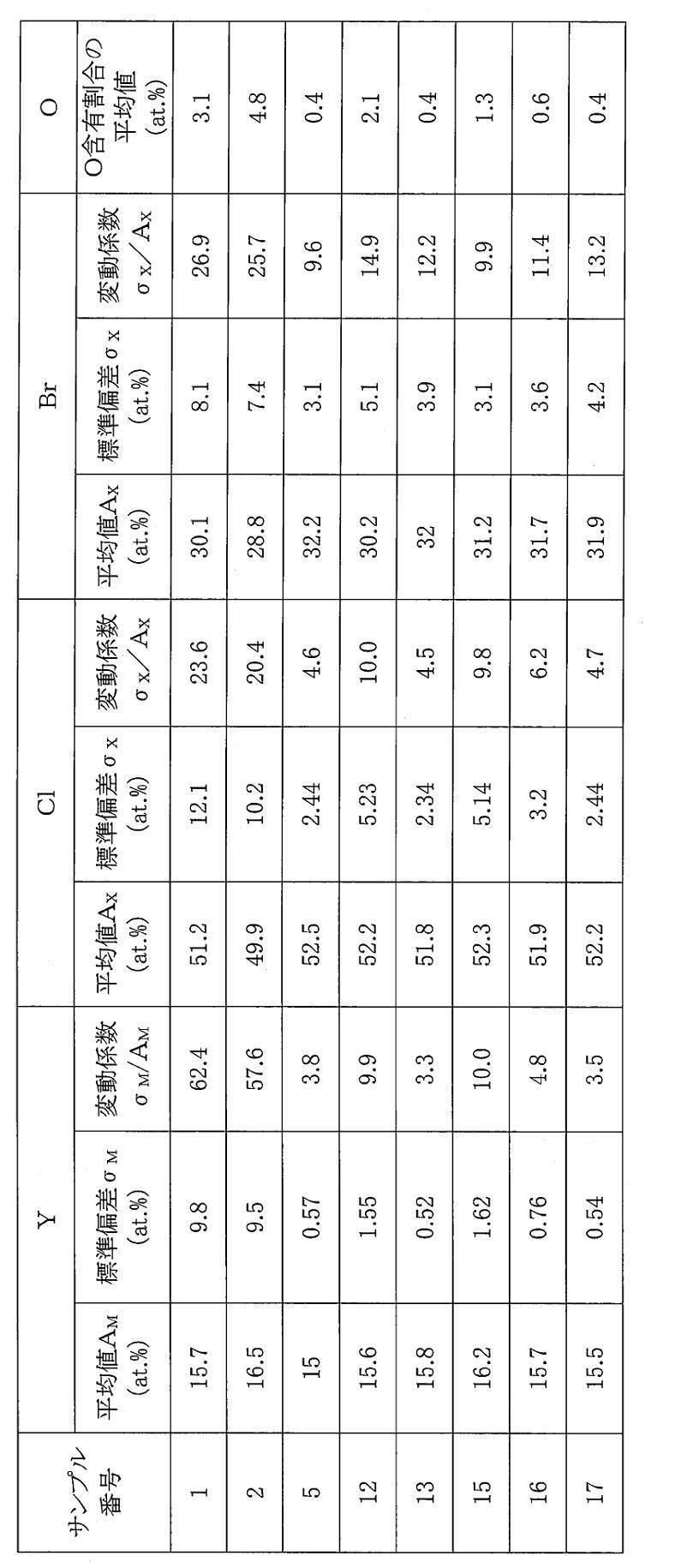
表1および表2に示されるように、サンプル1のように合成工程だけでは、得られる固体電解質の組成変動が大きかった。サンプル1の固体電解質の変動係数は、Yについては62.4、Clについては23.6、およびBrについては26.9であり、実施例としてのサンプルの固体電解質と比較して、非常に大きかった。
101 固体電解質の粉末
201 正極
202 電解質層
203 負極
204 正極活物質粒子
205 負極活物質粒子
1000 電池
Claims (15)
- Li、M、およびXを含む固体電解質であって、
前記Mは、Li以外の金属元素および半金属元素からなる群より選択される少なくとも1つであり、
前記Xは、F、Cl、Br、およびIからなる群より選択される少なくとも1つであり、
前記固体電解質において、
前記Mの含有割合の変動係数が10以下であり、かつ
前記Xの含有割合の変動係数が15以下である、
固体電解質であり、
ここで、前記固体電解質における前記Mおよび前記Xの含有割合の変動係数は、次の方法で求められる:
前記固体電解質について、前記Mの含有割合の平均値AMおよび標準偏差σMと、前記Xの含有割合の平均値AXおよび標準偏差σXと、を求め、
前記Mの平均値AMおよび標準偏差σMを用いて前記Mの含有割合の変動係数を求め、前記Xの含有割合の平均値AXおよび標準偏差σXを用いて前記Xの含有割合の変動係数を求める。 - 前記固体電解質において、Li原子を除く全ての原子の合計に対するO原子の含有割合の平均値が、2.5原子%以下である、
請求項1に記載の固体電解質であり、
ここで、Li原子を除く全ての原子の合計に対するO原子の含有割合の平均値は、次の方法で求められる:
前記固体電解質について、スポット径が1μmである任意の20個のスポットを設定し、各スポットについて電子線マイクロアナライザーにより、Li原子を除く全ての原子の合計に対するO原子の含有割合を求め、
次に、前記20個のスポットにおけるO原子の前記含有割合の結果から、O原子の前記含有割合の平均値を求める。 - 電子線マイクロアナライザーによって求められる前記Mの原子の含有割合が、以下の式(1)を満たす、
AM-3σM≦Mの原子の含有割合≦AM+3σM …(1)
請求項1または2に記載の固体電解質。 - 電子線マイクロアナライザーによって求められる前記Xの原子の含有割合が、以下の式(2)を満たす、
AX-3σX≦Xの原子の含有割合≦AX+3σX …(2)
請求項1から3のいずれか一項に記載の固体電解質。 - (A)Li、M、およびXを含むハロゲン化物を合成することと、
(B)前記ハロゲン化物を粉砕することと、
(C)前記ハロゲン化物を焼成することと、
を含み、
前記Mは、Li以外の金属元素および半金属元素からなる群より選択される少なくとも1つであり、
前記Xは、F、Cl、Br、およびIからなる群より選択される少なくとも1つであり、
前記(A)、前記(B)、および前記(C)がこの順で実施される、
固体電解質の製造方法。 - 前記(A)において、前記ハロゲン化物は、原料をメカノケミカルミリングの方法によって反応させることによって合成される、
請求項5に記載の製造方法。 - 前記(A)において、前記ハロゲン化物は、原料の混合物の焼成により合成される、
請求項5に記載の製造方法。 - 前記(B)において、前記ハロゲン化物は、得られる粉砕物が1cm以上の平均粒径を有するように粉砕される、
請求項5から7のいずれか一項に記載の製造方法であり、
ここで、前記平均粒径は、前記ハロゲン化物の粉砕物について、前記ハロゲン化物の粒子が少なくとも100個存在する大きさを一視野として前記粉砕物を光学顕微鏡によって観察し、得られた顕微鏡像において粒径が大きいものから順に50個の粒子を選択して粒径を測定し、得られた測定値から求められる値である。 - 前記(C)において、前記ハロゲン化物は、容器に入れられて焼成され、
前記ハロゲン化物の質量(単位はg)に対する前記容器の開口面積(単位はcm2)の比率は、0超かつ0.5以下である、
請求項5から8のいずれか一項に記載の製造方法。 - (D)前記ハロゲン化物を研磨処理すること、をさらに含む、
請求項5から9のいずれか一項に記載の製造方法。 - 最終的に得られる固体電解質の、原料の総質量からの減少質量D1に対する、前記(A)における減少質量D2の割合P1が、90%以上である、
請求項5から10のいずれか一項に記載の製造方法であり、
ここで、
前記(A)における減少質量D2は、前記(A)における合成前の原料の総質量からの、前記(A)において合成された前記ハロゲン化物の質量の差分であり、
前記割合P1は、(D2/D1)×100によって求められる。 - 最終的に得られる固体電解質の、原料の総質量からの減少質量D1に対する、前記(C)における減少質量D3の割合P2が、10%以下である、請求項5から11のいずれか一項に記載の製造方法であり、
ここで、
前記(C)における減少質量D3は、前記(B)の粉砕後かつ前記(C)の焼成前の前記ハロゲン化物の質量からの、前記(C)において焼成された後の前記ハロゲン化物の質量の差分であり、
前記割合P2は、(D3/D1)×100によって求められる。 - 前記Mは、Yを含む、
請求項5から12のいずれか一項に記載の製造方法。 - 前記Xは、ClおよびBrからなる群より選択される少なくとも1つを含む、
請求項5から13のいずれか一項に記載の製造方法。 - 正極、
負極、および
前記正極および前記負極の間に設けられている電解質層、
を備え、
前記正極、前記負極、および前記電解質層からなる群より選択される少なくとも1つは、請求項1から4のいずれか一項に記載の固体電解質を含有する、
電池。
Priority Applications (4)
| Application Number | Priority Date | Filing Date | Title |
|---|---|---|---|
| JP2023520791A JPWO2022239352A1 (ja) | 2021-05-10 | 2022-02-18 | |
| EP22807059.5A EP4339969A4 (en) | 2021-05-10 | 2022-02-18 | SOLID ELECTROLYTE, PROCESS FOR PRODUCING SOLID ELECTROLYTE AND BATTERY |
| CN202280030507.4A CN117203719A (zh) | 2021-05-10 | 2022-02-18 | 固体电解质、固体电解质的制造方法及电池 |
| US18/487,066 US20240047739A1 (en) | 2021-05-10 | 2023-10-14 | Solid electrolyte, method for producing solid electrolyte, and battery |
Applications Claiming Priority (2)
| Application Number | Priority Date | Filing Date | Title |
|---|---|---|---|
| JP2021-080074 | 2021-05-10 | ||
| JP2021080074 | 2021-05-10 |
Related Child Applications (1)
| Application Number | Title | Priority Date | Filing Date |
|---|---|---|---|
| US18/487,066 Continuation US20240047739A1 (en) | 2021-05-10 | 2023-10-14 | Solid electrolyte, method for producing solid electrolyte, and battery |
Publications (1)
| Publication Number | Publication Date |
|---|---|
| WO2022239352A2 true WO2022239352A2 (ja) | 2022-11-17 |
Family
ID=84029901
Family Applications (1)
| Application Number | Title | Priority Date | Filing Date |
|---|---|---|---|
| PCT/JP2022/006556 Ceased WO2022239352A2 (ja) | 2021-05-10 | 2022-02-18 | 固体電解質、固体電解質の製造方法、および電池 |
Country Status (5)
| Country | Link |
|---|---|
| US (1) | US20240047739A1 (ja) |
| EP (1) | EP4339969A4 (ja) |
| JP (1) | JPWO2022239352A1 (ja) |
| CN (1) | CN117203719A (ja) |
| WO (1) | WO2022239352A2 (ja) |
Cited By (2)
| Publication number | Priority date | Publication date | Assignee | Title |
|---|---|---|---|---|
| WO2025004754A1 (ja) * | 2023-06-29 | 2025-01-02 | パナソニックIpマネジメント株式会社 | ハロゲン化物固体電解質、正極材料、および電池 |
| WO2025052932A1 (ja) * | 2023-09-08 | 2025-03-13 | 出光興産株式会社 | 結晶性硫化物固体電解質及びその製造方法 |
Citations (1)
| Publication number | Priority date | Publication date | Assignee | Title |
|---|---|---|---|---|
| WO2020136951A1 (ja) | 2018-12-26 | 2020-07-02 | パナソニックIpマネジメント株式会社 | ハロゲン化物の製造方法 |
Family Cites Families (2)
| Publication number | Priority date | Publication date | Assignee | Title |
|---|---|---|---|---|
| CN112930319B (zh) * | 2018-12-26 | 2024-08-09 | 松下知识产权经营株式会社 | 固体电解质材料和使用该材料的电池 |
| CN115280426B (zh) * | 2020-03-31 | 2024-12-24 | 松下知识产权经营株式会社 | 固体电解质材料及使用了该固体电解质材料的电池 |
-
2022
- 2022-02-18 EP EP22807059.5A patent/EP4339969A4/en active Pending
- 2022-02-18 CN CN202280030507.4A patent/CN117203719A/zh active Pending
- 2022-02-18 JP JP2023520791A patent/JPWO2022239352A1/ja active Pending
- 2022-02-18 WO PCT/JP2022/006556 patent/WO2022239352A2/ja not_active Ceased
-
2023
- 2023-10-14 US US18/487,066 patent/US20240047739A1/en active Pending
Patent Citations (1)
| Publication number | Priority date | Publication date | Assignee | Title |
|---|---|---|---|---|
| WO2020136951A1 (ja) | 2018-12-26 | 2020-07-02 | パナソニックIpマネジメント株式会社 | ハロゲン化物の製造方法 |
Cited By (2)
| Publication number | Priority date | Publication date | Assignee | Title |
|---|---|---|---|---|
| WO2025004754A1 (ja) * | 2023-06-29 | 2025-01-02 | パナソニックIpマネジメント株式会社 | ハロゲン化物固体電解質、正極材料、および電池 |
| WO2025052932A1 (ja) * | 2023-09-08 | 2025-03-13 | 出光興産株式会社 | 結晶性硫化物固体電解質及びその製造方法 |
Also Published As
| Publication number | Publication date |
|---|---|
| CN117203719A (zh) | 2023-12-08 |
| EP4339969A4 (en) | 2025-07-16 |
| JPWO2022239352A1 (ja) | 2022-11-17 |
| US20240047739A1 (en) | 2024-02-08 |
| EP4339969A2 (en) | 2024-03-20 |
Similar Documents
| Publication | Publication Date | Title |
|---|---|---|
| US10938064B2 (en) | Sulfide-type compound particles, solid electrolyte, and lithium secondary battery | |
| KR102162070B1 (ko) | 리튬 이차전지용 황화물계 고체 전해질 | |
| JP7445876B2 (ja) | 固体電解質材料およびそれを用いた電池 | |
| WO2019009228A1 (ja) | リチウム二次電池の固体電解質及び当該固体電解質用硫化物系化合物 | |
| JPWO2020095937A1 (ja) | 硫黄含有化合物、固体電解質及び電池 | |
| JP7796724B2 (ja) | 固体電解質及びその製造方法 | |
| JPWO2020137026A1 (ja) | 固体電解質材料、およびそれを用いた電池 | |
| JP2020027715A (ja) | 結晶性硫化物系固体電解質の製造方法 | |
| JP7402711B2 (ja) | 全固体リチウムイオン二次電池用正極活物質、全固体リチウムイオン二次電池、及び全固体リチウムイオン二次電池用正極活物質の製造方法 | |
| TW202243992A (zh) | 固體電解質及其製造方法 | |
| US20240047739A1 (en) | Solid electrolyte, method for producing solid electrolyte, and battery | |
| CN118221122A (zh) | SiO粉末的制造方法及球形颗粒状SiO粉末 | |
| CN113614970A (zh) | 全固体二次电池 | |
| WO2025004749A1 (ja) | ハロゲン化物固体電解質の製造方法、ハロゲン化物固体電解質、正極材料、および電池 | |
| WO2021176759A1 (ja) | 電極材料および電池 | |
| US20230299285A1 (en) | Positive electrode active material and lithium-ion secondary battery | |
| WO2023199629A1 (ja) | 固体電解質材料およびそれを用いた電池 | |
| WO2023195271A1 (ja) | 固体電解質材料およびそれを用いた電池 | |
| WO2023127830A1 (ja) | 複合活物質 | |
| WO2025004752A1 (ja) | 固体電解質の製造方法、固体電解質、正極材料、および電池 | |
| WO2025004753A1 (ja) | ハロゲン化物固体電解質の製造方法、ハロゲン化物固体電解質、正極材料、および電池 | |
| WO2025004751A1 (ja) | 固体電解質、固体電解質の製造方法、正極材料、および電池 | |
| TWI906495B (zh) | 固體電解質及其製造方法 | |
| WO2025004750A1 (ja) | ハロゲン化物固体電解質の製造方法、ハロゲン化物固体電解質、正極材料、および電池 | |
| WO2025004748A1 (ja) | ハロゲン化物固体電解質の製造方法、ハロゲン化物固体電解質、正極材料、および電池 |
Legal Events
| Date | Code | Title | Description |
|---|---|---|---|
| 121 | Ep: the epo has been informed by wipo that ep was designated in this application |
Ref document number: 22807059 Country of ref document: EP Kind code of ref document: A2 |
|
| WWE | Wipo information: entry into national phase |
Ref document number: 2023520791 Country of ref document: JP |
|
| WWE | Wipo information: entry into national phase |
Ref document number: 202280030507.4 Country of ref document: CN |
|
| WWE | Wipo information: entry into national phase |
Ref document number: 2022807059 Country of ref document: EP |
|
| NENP | Non-entry into the national phase |
Ref country code: DE |
|
| ENP | Entry into the national phase |
Ref document number: 2022807059 Country of ref document: EP Effective date: 20231211 |