WO2022239286A1 - ボールねじ装置 - Google Patents
ボールねじ装置 Download PDFInfo
- Publication number
- WO2022239286A1 WO2022239286A1 PCT/JP2021/045502 JP2021045502W WO2022239286A1 WO 2022239286 A1 WO2022239286 A1 WO 2022239286A1 JP 2021045502 W JP2021045502 W JP 2021045502W WO 2022239286 A1 WO2022239286 A1 WO 2022239286A1
- Authority
- WO
- WIPO (PCT)
- Prior art keywords
- ball
- nut
- balls
- screw device
- retainer
- Prior art date
- Legal status (The legal status is an assumption and is not a legal conclusion. Google has not performed a legal analysis and makes no representation as to the accuracy of the status listed.)
- Ceased
Links
Images







Classifications
-
- F—MECHANICAL ENGINEERING; LIGHTING; HEATING; WEAPONS; BLASTING
- F16—ENGINEERING ELEMENTS AND UNITS; GENERAL MEASURES FOR PRODUCING AND MAINTAINING EFFECTIVE FUNCTIONING OF MACHINES OR INSTALLATIONS; THERMAL INSULATION IN GENERAL
- F16H—GEARING
- F16H25/00—Gearings comprising primarily only cams, cam-followers and screw-and-nut mechanisms
- F16H25/18—Gearings comprising primarily only cams, cam-followers and screw-and-nut mechanisms for conveying or interconverting oscillating or reciprocating motions
- F16H25/20—Screw mechanisms
- F16H25/22—Screw mechanisms with balls, rollers, or similar members between the co-operating parts; Elements essential to the use of such members
Definitions
- the present invention relates to a ball screw device.
- Patent Literature 1 discloses a ball screw device that can be applied to an automobile brake device.
- This ball screw device includes a screw shaft having a first helical groove on its outer circumference, a nut having a second helical groove on its inner circumference forming a helical track between the first helical groove and a plurality of helical grooves arranged on the helical track. and a row of balls consisting of Rotation of the screw shaft causes the nut to move along the axial direction of the screw shaft.
- the ball screw device disclosed in Patent Document 1 is not a type device in which a plurality of balls circulate when the nut moves, but a non-circulating device in which a plurality of balls stay and roll within the helical orbit of the nut. be.
- the conventional non-circulating ball screw device includes a first coil spring provided within the spiral track and abutting one end of the ball row, and a second coil spring provided within the spiral track and abutting the other end of the ball row. It has In the above ball screw device, both ends of the ball train are held by both coil springs. When a rotational force is applied to the screw shaft and it rotates relative to the nut, the ball train moves within the helical orbit within the expansion and contraction range of both coil springs. to move the nut axially. Therefore, the stroke of the screw shaft that accompanies the movement of the ball row is determined according to the amount of expansion and contraction of the coil spring.
- a ball screw device includes: a screw shaft having a first spiral groove on its outer periphery; a nut having a second spiral groove on its inner periphery forming a spiral track between the first spiral groove and the spiral track; and a retainer disposed in an annular space between the screw shaft and the nut to hold the plurality of balls.
- the retainer includes an annular portion arranged in the annular space so as to be rotatable around the center line of the screw shaft and immovable relative to the nut in the axial direction, and one side of the annular portion in the axial direction.
- a plurality of pillars extending from the end face in one axial direction and intersecting the spiral track at a plurality of points, and provided between a pair of pillars adjacent in the circumferential direction among the plurality of pillars to allow the plurality of balls to roll. and a plurality of pockets for holding in.
- a ball screw device viewed from another point of view includes a screw shaft having a first spiral groove on the outer circumference and a second spiral groove forming a spiral track between the screw shaft and the first spiral groove on the inner circumference.
- a nut a ball row including a plurality of balls arranged on the helical raceway, and a retainer arranged in an annular space between the screw shaft and the nut to hold the plurality of balls, Prepare.
- the retainer includes a cylindrical main body portion arranged in the annular space so as to be rotatable around the center line of the screw shaft and immovable relative to the nut in the axial direction, and the main body portion along the circumferential direction. and a plurality of pockets provided in the portion to hold the plurality of balls, the plurality of pockets extending along the axial direction and intersecting the spiral track at a plurality of points.
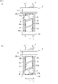
- FIG. 1 is a perspective view of a ball screw device according to a first embodiment.
- FIG. FIG. 2 is a cross-sectional view of the ball screw device.
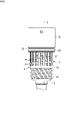
- FIG. 3(a) is a perspective view showing a retainer arranged on the outer peripheral side of the screw shaft, and
- FIG. 3(b) is a perspective view showing the retainer.
- 4A and 4B are diagrams showing the positional relationship between the retainer and the balls.
- FIG. 4A shows the case where the row of balls is located at the first position
- FIG. 4B shows the case where the row of balls is located at the second position. It is a figure which shows.
- FIG. 5 is a cross-sectional view of essential parts of a ball screw device according to a modification of the first embodiment.
- FIG. 5 is a cross-sectional view of essential parts of a ball screw device according to a modification of the first embodiment.
- FIG. 6 is an exploded perspective view of the ball screw device according to the second embodiment.
- FIG. 7 is a cross-sectional view of essential parts of a ball screw device according to a second embodiment.
- FIG. 8 is a diagram showing the retainer arranged on the outer peripheral side of the screw shaft.
- FIG. 9 is a diagram showing a retainer of a ball screw device according to a modification of the second embodiment.
- FIG. 10 is a diagram showing a retainer of a ball screw device according to a second modification of the second embodiment.
- FIG. 11 is an enlarged view of the second inner end face of the connecting annular portion in FIG. 10;
- FIG. 12 is a plan view of the cage developed.
- a ball screw device includes a screw shaft having a first spiral groove on its outer periphery; A ball row including a plurality of balls arranged on the spiral track, and a retainer arranged in an annular space between the screw shaft and the nut to hold the plurality of balls.
- the retainer includes an annular portion arranged in the annular space so as to be rotatable around the center line of the screw shaft and immovable relative to the nut in the axial direction, and one side of the annular portion in the axial direction.
- a plurality of pillars extending from the end face in one axial direction and intersecting the spiral track at a plurality of points, and provided between a pair of pillars adjacent in the circumferential direction among the plurality of pillars to allow the plurality of balls to roll. and a plurality of pockets for holding in.
- the pocket since the pocket is provided between the columns that intersect the spiral track at a plurality of points, the pocket extends along the axial direction and intersects the spiral track at a plurality of points.
- Each ball is held at the intersection of the pocket and the helical track.
- the retainer rotates in response to the movement of the row of balls.
- Each ball then moves axially along the retainer pocket.
- the row of balls can move within the spiral track to the extent that each ball can move axially along the pocket. Therefore, the stroke accompanying the movement of the ball row can be determined by the axial length of the pocket, and the stroke accompanying the movement of the ball row can be increased compared to the case where the coil spring is used as in the above conventional example. can be secured to a large extent.
- the retainer further includes a connecting annular portion that connects ends of the plurality of columns on one side in the axial direction.
- the rigidity of the retainer can be increased by the connecting annular portion.
- a circumferential interval between the pair of pillars may be an interval capable of holding one ball.
- one ball is held at the intersection of the pocket and the spiral track. Therefore, when assembling the ball screw device, each ball may be arranged at the intersection of the pocket and the helical track (first helical groove or second helical groove). Assembly is easier than when a plurality of balls are held in place.
- a circumferential interval between the pair of pillars may be an interval capable of holding a predetermined number of balls, which is two or more. In this case, a plurality of balls are held at intersections of the pockets and the spiral tracks. Therefore, the number of pillars can be reduced compared to the case where one ball is held at the intersection of the pocket and the spiral track.
- the predetermined number of balls are held in each of the plurality of pockets.
- the ball screw device preferably further includes a friction member provided between the nut and the annular portion to provide resistance to rotation of the retainer with respect to the nut.
- the ball screw device functions as a sliding screw when the rotational torque acting between the screw shaft and the nut is so low that the retainer and the nut are held so that they can rotate integrally due to the resistance of the friction member.
- the rotational torque acting between the screw shaft and the nut is large enough to prevent the retainer and the nut from rotating integrally due to the resistance of the friction member, the retainer rotates with respect to the screw shaft and the nut, Functions as a ball screw.
- switching between the state of functioning as a slide screw and the state of functioning as a ball screw can be performed according to the rotational torque acting between the screw shaft and the nut. Further, by adjusting the resistance of the friction member, it is possible to adjust the switching timing between the state of functioning as a sliding screw and the state of functioning as a ball screw.
- the friction member may include a rubber ring interposed between the nut and the outer peripheral surface of the annular portion.
- a frictional force can be generated between the nut and the annular portion with a simple structure, and resistance can be applied to the rotation of the retainer with respect to the nut.
- the nut has a cylindrical inner peripheral surface that accommodates the annular portion radially inward, and a cylindrical inner peripheral surface that extends radially inward from the cylindrical inner peripheral surface and a second radially inner peripheral surface. and a stepped surface connecting with the spiral groove, wherein the friction member presses the annular portion to one side in the axial direction, and presses the stepped surface facing the one end surface of the annular portion and the one end surface.
- Abutting wave washers may be included. In this case, a frictional force can be generated between the nut and the annular portion by contacting and pressing the step surface and the one end surface. Also, by selecting the dimensions and characteristics of the wave washer, it is possible to easily adjust the resistance applied between the nut and the retainer.
- each of the plurality of pockets is defined by side surfaces of the pair of pillars and a first inner end surface of the annular portion, and the first inner end surface extends along the circumferential direction. It has one circumferential surface and a first inclined surface, and the first end portion of the first circumferential surface is located at one of the circumferential both end portions of the first circumferential surface when the pocket is viewed from the front.
- the first helical groove has a smaller axial distance from the top of the groove, and the first inclined surface is a first side surface of the pair of pillars on the first end side, provided so as to connect with the first end, slanted so as to approach the second side of the pair of pillars as it goes from the first side toward the first end, and the first slanted
- the surface is contactable with the ball in contact with the second side surface, and the first circumferential surface is contactable with the ball when the ball contacts the first inclined surface and the second side surface. It is preferable that it is a surface that does not come into contact with the surface.
- the ball moving along the spiral track reaches the first inner end surface, the ball can be brought into contact with the first inclined surface without contacting the first circumferential surface.
- the first inclined surface is inclined so as to approach the second side surface as it goes from the first side surface toward the first end, the groove top located on one side in the axial direction with respect to the ball and the first The angle formed with the inclined surface can be made relatively large. As a result, it is possible to suppress the ball from getting caught between the spiral track and the first inclined surface. Therefore, when the ball moving along the spiral track reaches the first inner end surface and contacts the first inclined surface, it is possible to prevent the ball from being caught between the spiral track and the first inclined surface. can be done.
- the retainer further includes a connecting annular portion that connects ends of the plurality of pillars on one side in the axial direction, and each of the pockets includes side surfaces of the pair of pillars and the annular and a second inner end surface of the connecting annular portion, the second inner end surface having a second circumferential surface along the circumferential direction and a second inclined surface;
- the second end of each of the two circumferential surfaces has a smaller axial distance from the top of the first spiral groove when the pocket is viewed from the front, of the two circumferential ends of the second circumferential surface.
- the second inclined surface which is an end portion, is provided so as to connect a second side surface on the second end side among the side surfaces of the pair of columns and the second end portion, and the second side surface is an end portion.
- the second inclined surface is inclined to approach the first side surface of the pair of side surfaces of the column, and the second inclined surface can contact the ball in contact with the first side surface.
- the second circumferential surface is a surface that does not come into contact with the ball when the ball contacts the second inclined surface and the first side surface.
- the second inclined surface is inclined so as to approach the first side surface as it goes from the second side surface toward the second end, the groove top located on the other side in the axial direction with respect to the ball and the second The angle formed with the inclined surface can be made relatively large. As a result, it is possible to suppress the ball from getting caught between the spiral track and the second inclined surface. Therefore, when the ball moving along the spiral track reaches the second inner end surface and comes into contact with the second inclined surface, it is possible to prevent the ball from getting caught between the spiral track and the second inclined surface. can be done.
- the plurality of second inner end faces are arranged along the lead angle direction of the first spiral groove.
- the plurality of balls can be brought into contact with the plurality of second inner end surfaces at the same timing.
- the force acting from the screw shaft and the nut can be evenly distributed among the plurality of balls, and the biting of the balls can be effectively suppressed.
- a ball screw device which is an embodiment viewed from another point of view, includes a screw shaft having a first spiral groove on its outer periphery, and a second spiral groove forming a spiral track between the first spiral groove and the screw shaft.
- a nut provided on the circumference, a ball row including a plurality of balls arranged on the spiral track, a retainer arranged in an annular space between the screw shaft and the nut and holding the plurality of balls;
- the retainer includes a cylindrical main body portion arranged in the annular space so as to be rotatable around the center line of the screw shaft and immovable relative to the nut in the axial direction, and the main body portion along the circumferential direction. and a plurality of pockets provided in the portion for holding the plurality of balls. The plurality of pockets extend along the axial direction and intersect the spiral track at a plurality of points.
- FIG. 1 is a perspective view of a ball screw device according to a first embodiment
- FIG. 2 is a cross-sectional view of the ball screw device. Note that FIG. 2 is a cross-sectional view along a plane including the center line of the ball screw device.
- This ball screw device 1 is used for a brake device of a vehicle such as an automobile, a power transmission device including a multi-plate clutch, and the like.
- a ball screw device 1 includes a screw shaft 2 , a nut 4 provided on the outer peripheral side of the screw shaft 2 , a plurality of balls 6 , and a retainer 8 that holds the plurality of balls 6 .
- the direction parallel to the center line C of the screw shaft 2 is defined as the axial direction
- the direction orthogonal to the center line C is defined as the radial direction
- the direction along the circle centered on the center line C is defined as the circumferential direction.
- direction. 1 and 2 the side where the snap ring 9 is not provided in the opening of the nut 4 in the axial direction is defined as one axial side
- the side where the snap ring 9 is provided is defined as the other axial side.
- the screw shaft 2 is inserted through the nut 4 and has a first spiral groove 10 on its outer circumference.
- the nut 4 is a cylindrical member.
- the centerline of the nut 4 coincides with the centerline C.
- the nut 4 has a second spiral groove 12 on its inner circumference.
- a cylindrical inner peripheral surface 4a is provided at the end of the inner periphery of the nut 4 on the other side in the axial direction.
- the first helical groove 10 of the screw shaft 2 and the second helical groove 12 of the nut 4 constitute a helical track 14 in which a plurality of balls 6 are arranged.
- the outer diameter dimension of the groove top portion 10 a of the first spiral groove 10 is smaller than the inner diameter dimension of the groove top portion 12 a of the second spiral groove 12 . Therefore, an annular space K is provided between the screw shaft 2 and the nut 4 .
- a retainer 8 is arranged in an annular space K between the screw shaft 2 and the nut 4 .
- the retainer 8 comprises an annular portion 20 and a plurality of posts 22 .
- the annular portion 20 is accommodated radially inward of the cylindrical inner peripheral surface 4a.
- the annular portion 20 is arranged between the cylindrical inner peripheral surface 4 a and the screw shaft 2 .
- An annular groove 4b in which a retaining ring 9 is fitted is provided in the cylindrical inner peripheral surface 4a.
- One end face 20 a on one axial side of the annular portion 20 faces the stepped face 24 of the nut 4 .
- the step surface 24 is a surface that extends radially inward from the cylindrical inner peripheral surface 4 a and connects between the cylindrical inner peripheral surface 4 a and the second spiral groove 12 . Further, the other end surface 20 b on the other axial side of the annular portion 20 faces the inner surface 9 a of the retaining ring 9 .
- a slight clearance is provided between the inner peripheral surface 20c of the annular portion 20 and the groove top portion 10a of the first spiral groove 10 of the screw shaft 2. As shown in FIG. A slight clearance is also provided between the outer peripheral surface 20d of the annular portion 20 and the cylindrical inner peripheral surface 4a. Thereby, the annular portion 20 is arranged in the annular space K so as to be rotatable around the center line C and axially immovable relative to the nut 4 .
- An outer peripheral surface 20d of the annular portion 20 is provided with an outer peripheral groove 20d1.
- a friction member 26 is provided in the outer peripheral groove 20d1.
- the friction member 26 is a rubber ring.
- the friction member 26 is fitted in the outer peripheral groove 20d1.
- the friction member 26 is interposed between the cylindrical inner peripheral surface 4a and the outer peripheral groove 20d1, and is in contact with the cylindrical inner peripheral surface 4a and the outer peripheral groove 20d1. That is, the friction member 26 is provided between the nut 4 and the annular portion 20 .
- the friction member 26 provides resistance to the rotation of the retainer 8 with respect to the nut 4 by the frictional force generated by contacting the cylindrical inner peripheral surface 4a and the outer peripheral groove 20d1.
- the retainer 8 rotates integrally with the nut 4, causing the retainer 8 to rotate relatively. is greater than the resistance of the friction member 26, the retainer 8 can rotate relative to the nut 4.
- a plurality of columns 22 of the retainer 8 extend from one end surface 20a of the annular portion 20 to one side in the axial direction.
- the retainer 8 of this embodiment comprises three posts 22 .
- the three pillars 22 are arranged at regular intervals in the circumferential direction.
- FIG. 3(a) is a perspective view showing the retainer 8 arranged on the outer peripheral side of the screw shaft 2
- FIG. 3(b) is a perspective view showing the retainer 8.
- FIG. 1 As shown in FIGS. 2 and 3, the three pillars 22 extend across between the groove crest 10a of the first spiral groove 10 of the screw shaft 2 and the groove crest 12a of the second spiral groove 12 of the nut 4. It extends in the axial direction and intersects the spiral track 14 at a plurality of points.
- the retainer 8 also includes a connecting annular portion 30 that connects the ends 22a of the columns 22 on one side in the axial direction.
- the centerline of the connecting annular portion 30 coincides with the centerline C and is concentric with the annular portion 20 .
- One axial end surface 30 a of the connecting annular portion 30 substantially coincides with the axial one end surface 4 c of the nut 4 . In this manner, the connecting annular portion 30 is provided at one end portion of the nut 4 in the axial direction.
- the retainer 8 further comprises a plurality of pockets 32 that hold a plurality of balls 6 rollably.
- the pocket 32 is provided between a pair of pillars 22 adjacent in the circumferential direction among the three pillars 22 . Therefore, the retainer 8 of this embodiment has three pockets 32 .
- the pocket 32 is a rectangular space surrounded by a pair of pillars 22 adjacent in the circumferential direction, the annular portion 20 and the connecting annular portion 30 . Therefore, the pocket 32 extends along the axial direction and intersects the spiral track 14 at a plurality of points.
- the pocket 32 is defined by the side surfaces 22b of a pair of circumferentially adjacent columns 22, the first inner end surface 32a of the annular portion 20, and the second inner end surface 32b of the connecting annular portion 30.
- the first inner end surface 32 a is an end surface on one side in the axial direction of the annular portion 20 .
- the second inner end surface 32b is an end surface of the connecting annular portion 30 on the other side in the axial direction.
- the pair of side surfaces 22b extend along the axial direction.
- a plurality of balls 6 are arranged in a spiral track 14 to form a ball row L.
- the ball row L includes six balls 6 in this embodiment.
- the circumferential interval between a pair of pillars 22 adjacent in the circumferential direction is the interval that allows two balls 6 to be held. Therefore, three pillars 22 intervene in the row L of balls.
- the three pillars 22 intervene so as to divide the balls 6 of the ball row L arranged in the row longitudinal direction into three. That is, each of the three pockets 32 holds two balls 6 aligned in the row longitudinal direction.
- the ball screw device 1 functions as a ball screw as the ball train L moves within the spiral track 14 .
- the balls 6 are held in the pockets 32 , the movement range of the ball row L in the axial direction is limited by the retainer 8 .
- the ball 6 a located at the end of the ball row L on the other side in the axial direction among the six balls 6 is the first inner end surface 32 a of the annular portion 20 and the side surface of the column 22 . 22b, the axial position of the ball row L in the retainer 8 is the position closest to the other side in the axial direction (first position).
- the nut 4 is abbreviate
- the ball screw device 1 rotates the screw shaft 2 relative to the nut 4 and functions as a ball screw while the row of balls L moves from the first position to the second position.
- the screw shaft 2 is further rotated relative to the nut 4 after the ball train L reaches the second position from the first position, the movement of the ball train L in the axial direction is restricted.
- 1 does not function as a ball screw, but functions as a slide screw.
- the ball screw device 1 functions as a ball screw even while the row of balls L moves from the second position to the first position.
- the screw shaft 2 is further rotated relative to the nut 4 after the ball row L reaches the first position from the second position, the movement of the ball row L in the axial direction is also restricted in this case.
- the ball screw device 1 does not function as a ball screw, but functions as a slide screw.
- the ball screw device 1 rotates the screw shaft 2 relative to the nut 4 and functions as a ball screw while the row of balls L moves between the first position and the second position in the retainer 8. do.
- the ball screw device 1 functions as a slide screw.
- the ball screw device 1 configured as described above applies a rotational force to the screw shaft 2 and causes the screw shaft 2 to rotate relative to the nut 4 , thereby moving the nut along the axial direction and rotating the screw shaft 2 .
- a rotational force used for converting motion into linear motion.
- the ball screw device 1 functions as a ball screw to transmit power to the screw shaft 2.
- the nut 4 is moved in the axial direction. That is, during the stroke of the ball screw device 1, the rotational force applied to the screw shaft 2 is decelerated while the row of balls L moves between the first position and the second position.
- the ball screw device 1 functions as a sliding screw and moves the nut 4 in the axial direction according to the rotation applied to the screw shaft 2 .
- the pockets 32 are provided between the columns 22 that intersect the spiral track 14 at a plurality of points, the pockets 32 extend along the axial direction and intersect the spiral track 14 at a plurality of points.
- Each ball 6 is held at the point where the pocket 32 and the spiral track 14 intersect.
- the retainer 8 rotates according to the movement of the row of balls L.
- each ball 6 moves axially along the pocket 32 of the retainer 8 . Therefore, the ball row L can move within the spiral track 14 within a range in which each ball 6 can move axially along the pocket 32 .
- the stroke that accompanies the movement of the ball row L can be determined by the axial length of the pocket 32, and the stroke that accompanies the movement of the ball row can be compared with the conventional example using the coil spring. can be secured to a greater extent.
- the ball screw device 1 can be switched between a state in which it functions as a slide screw and a state in which it functions as a ball screw. You can adjust the switching timing. For example, when the screw shaft 2 and the nut 4 are relatively rotated to move the nut 4 to the other side in the axial direction from the state shown in FIG. When the applied rotational torque is relatively small, the friction member 26 holds the retainer 8 rotatably integrally with the nut 4 by the resistance generated by contacting the nut 4 and the annular portion 20 . When the retainer 8 does not rotate relative to the nut 4, the ball rows L do not move within the spiral track 14, so the ball screw device 1 functions as a slide screw.
- the friction member 26 is provided between the nut 4 and the annular portion 20 of the retainer 8, switching between the state of functioning as a slide screw and the state of functioning as a ball screw can be performed. It can be done according to the rotational torque acting between the screw shaft 2 and the nut 4 . Further, by adjusting the resistance of the friction member 26, it is possible to adjust the switching timing between the state of functioning as a sliding screw and the state of functioning as a ball screw.
- the friction member 26 is composed of a rubber ring, a frictional force can be generated between the nut 4 and the annular portion 20 with a simple configuration, and the rotation of the retainer 8 with respect to the nut 4 is resisted. can be granted.
- the retainer 8 since the retainer 8 includes the connecting annular portion 30 at the tip 22a of the column 22, the rigidity of the retainer 8 can be increased. Further, by providing the connecting annular portion 30, the ball 6b at the end portion on the one axial side in the ball row L when the axial position of the ball row L is the first position moves further to the one axial side. can be more tightly bounded.
- the circumferential interval between a pair of pillars 22 adjacent in the circumferential direction is an interval capable of holding two balls 6, the position where the pocket 32 and the spiral track 14 intersect is , two balls 6 are held. Therefore, the number of pillars 22 can be reduced compared to the case where one ball 6 is held at the intersection of the pocket 32 and the spiral track 14 .
- FIG. 5 is a cross-sectional view of essential parts of a ball screw device 1 according to a modification of the first embodiment.
- the friction member 26 is configured by a rubber ring, but in this modified example, the friction member 26 is configured by a wave washer.
- the friction member 26 of this embodiment is interposed between the other end surface 20b of the annular portion 20 and the inner side surface 9a of the retaining ring 9, and presses the annular portion 20 (retainer 8) to one side in the axial direction.
- the friction member 26 brings the stepped surface 24 of the nut 4 into contact with the one end surface 20a of the annular portion 20, and the frictional force between the stepped surface 24 and the one end surface 20a causes the retainer 8 to move against the nut 4. gives resistance to the rotation of
- a frictional force can be generated between the nut 4 and the annular portion 20 by bringing the stepped surface 24 and the one end surface 20a into contact and pressing them. Further, by selecting the dimensions and characteristics of the friction member 26, which is a wave washer, the frictional force between the step surface 24 and the one end surface 20a can be easily adjusted. The resistance imparted between can be easily adjusted. As a result, it is possible to easily adjust the switching timing between the state of functioning as a sliding screw and the state of functioning as a ball screw.
- FIG. 6 is an exploded perspective view of the ball screw device 1 according to the second embodiment
- FIG. 7 is a cross-sectional view of the essential parts of the ball screw device 1 according to the second embodiment. 6 and 7, the ball 6 is omitted.
- the ball screw device 1 of this embodiment also has a screw shaft 2 having a first spiral groove 10 on its outer periphery and a second spiral groove forming a spiral raceway 14 between the first spiral groove 10 and the first spiral groove 10 . 12 on the inner circumference, a ball row L including a plurality of balls 6 arranged on a spiral track 14, and a plurality of balls 6 arranged in an annular space K between the screw shaft 2 and the nut 4. and a retainer 8 that holds the Further, the retainer 8 includes an annular portion 20 arranged in the annular space K so as to be rotatable around the center line C of the screw shaft 2 and immovable relative to the nut 4 in the axial direction.
- a plurality of pillars 22 extending from one end face 20 a on one side to one side in the axial direction and intersecting the spiral track 14 at a plurality of points;
- a plurality of pockets 32 are provided between a pair of pillars adjacent to each other in the direction and hold a plurality of balls 6 in a rollable manner.
- This embodiment has a sleeve 36 arranged on the other side in the axial direction of the retainer 8, and the circumferential interval between a pair of pillars 22 adjacent in the circumferential direction is such that one ball 6 can be held. is different from the first embodiment.
- the sleeve 36 is arranged on the outer peripheral side of the screw shaft 2 and is internally fitted and fixed to the cylindrical inner peripheral surface 4 a of the nut 4 .
- One end face 36 a on one side in the axial direction of the sleeve 36 abuts the other end face 20 b of the annular portion 20 .
- the annular portion 20 is made immovable relative to the nut 4 in the axial direction by the step surface 24 of the nut 4 and the one end surface 36 a of the sleeve 36 .
- FIG. 8 is a diagram showing the retainer 8 arranged on the outer peripheral side of the screw shaft 2.
- the retainer 8 of this embodiment has 14 pillars 22 .
- the retainer 8 thus has 14 pockets 32 .
- the ball row L of this embodiment includes 14 balls 6, for example.
- Each pocket 32 thus holds one ball 6 .
- one ball 6 is held at the intersection of the pocket 32 and the spiral track 14 . Therefore, when assembling the ball screw device 1 , each ball 6 may be arranged at the intersection of the pocket 32 and the helical track 14 (first helical groove 10 or second helical groove 12 ). As compared with the case where a plurality of balls 6 are held at the intersection of the spiral track 14 and the spiral track 14, the assembly becomes easier.
- FIG. 9 is a diagram showing a retainer 8 of a ball screw device 1 according to a first modified example of the second embodiment.
- the first inner end surface 32a of the annular portion 20 is configured to include a circumferential surface 32a1 along the circumferential direction and an inclined surface 32a2 inclined with respect to the circumferential surface 32a1.
- the second embodiment is characterized in that the second inner end surface 32b of the connecting annular portion 30 includes a circumferential surface 32b1 along the circumferential direction and an inclined surface 32b2 inclined with respect to the circumferential surface 32b1.
- an inclined surface 32a2 is provided on the side of the one end 32a11 that has a smaller axial distance from the groove top portion 10a when the pocket 32 is viewed from the front. ing.
- the one end portion 32a11 is an end portion on one side in the circumferential direction of the both circumferential direction end portions of the circumferential direction surface 32a1.
- the inclined surface 32a2 is provided so as to connect one end portion 32a11 of the circumferential surface 32a1 and the side surface 22b of the column 22 .
- the inclined surface 32a2 is inclined in one axial direction from the one end 32a11 toward the side surface 22b of the column 22 . Therefore, the angle formed by the inclined surface 32a2 and the side surface 22b is 90 degrees or more.
- the inclined surface 32b2 is located on the side of the other end 32b11 which is closer to the groove crest 10a in the axial direction. is provided.
- the other end portion 32b11 is an end portion on the other side in the circumferential direction among both circumferential direction end portions of the circumferential surface 32b1.
- the inclined surface 32b2 is provided so as to connect the other end portion 32b11 of the circumferential surface 32b1 and the side surface 22b of the column 22 .
- the inclined surface 32b2 is inclined toward the other side in the axial direction from the other end portion 32b11 toward the side surface 22b. Therefore, the angle formed by the inclined surface 32b2 and the side surface 22b is 90 degrees or more.
- the axial position of the ball row L is located at the second position, and when the ball 6b located at one end in the axial direction of the ball row L contacts the second inner end surface 32b and the side surface 22b of the column 22, the ball 6b contacts the side surface 22b of the column 22 and the inclined surface 32b2 of the second inner end surface 32b. At this time, since the angle formed by the inclined surface 32b2 and the side surface 22b is 90 degrees or more, it is possible to prevent the ball 6b from getting caught between the inclined surface 32b2 and the side surface 22b.
- FIG. 10 is a diagram showing a retainer 8 of a ball screw device 1 according to a second modified example of the second embodiment.
- This second modification is the first modification in that the plurality of first inner end surfaces 32a and the plurality of second inner end surfaces 32b are arranged along the lead angle direction of the spiral track 14 (first spiral groove 10). differ from
- the first inner end surface 32a of the annular portion 20 includes a circumferential surface 32a1 along the circumferential direction and an inclined surface 32a2.
- the second inner end surface 32b of is configured to include a circumferential surface 32b1 along the circumferential direction and an inclined surface 32b2.
- one end portion 32a11 (first end portion) is an end portion on one side in the circumferential direction of the circumferential surface 32a1 (first circumferential surface).
- the other end portion 32a12 is an end portion on the other side in the circumferential direction of the circumferential surface 32a1.
- the axial distance between the one end portion 32a11 and the groove top portion 10a when the pocket 32 is viewed from the front is smaller than the axial distance between the other end portion 32a12 and the groove top portion 10a. That is, the one end portion 32a11 of the circumferential surface 32a1 is the end portion having a smaller axial distance from the groove top portion 10a when the pocket 32 is viewed from the front, among the both end portions of the circumferential surface 32a1.
- the inclined surface 32a2 (first inclined surface) is provided so as to connect the first side surface 22b1 and the one end portion 32a11.
- the inclined surface 32a2 connects the end portion 22b11 of the first side surface 22b1 and the one end portion 32a11.
- the inclined surface 32a2 is inclined so as to approach the second side surface 22b2 as it goes from the first side surface 22b1 toward the one end portion 32a11.
- the first side surface 22 b 1 is the side surface 22 b on the one end 32 a 11 side of the side surfaces 22 b of the pair of columns 22 that define the pocket 32 .
- the second side surface 22b2 is the other side surface of the side surfaces 22b of the pair of pillars 22 .
- the angle formed by the inclined surface 32a2 and the first side surface 22b1 is 90 degrees or more.
- the inclined surface 32a2 can contact the ball 6 that is in contact with the second side surface 22b2.
- the circumferential surface 32a1 is a surface that does not come into contact with the ball 6 when the ball 6 contacts the inclined surface 32a2 and the second side surface 22b2.
- the axial distance between the other end portion 32b11 and the groove top portion 10a when the pocket 32 is viewed from the front is smaller than the axial distance between the one end portion 32b12 and the groove top portion 10a.
- the one end portion 32b12 is an end portion on one side in the circumferential direction of the circumferential surface 32b1.
- the other end portion 32b11 (second end portion) is the end portion on the other circumferential side of the circumferential surface 32b1 (second circumferential surface). That is, the other end portion 32b11 of the circumferential surface 32b1 is the end portion having a smaller axial distance from the groove top portion 10a when the pocket 32 is viewed from the front, among both end portions of the circumferential surface 32b1.
- the inclined surface 32b2 (second inclined surface) is provided so as to connect the second side surface 22b2 and the other end portion 32b11.
- the inclined surface 32b2 connects the end portion 22b21 of the second side surface 22b2 and the other end portion 32b11.
- the inclined surface 32b2 is inclined so as to approach the first side surface 22b1 from the second side surface 22b2 toward the other end portion 32b11.
- the second side surface 22b2 is the side surface 22b on the other end 32b11 side of the side surfaces 22b of the pair of columns 22 that define the pocket 32 .
- the angle formed by the inclined surface 32b2 and the second side surface 22b2 is 90 degrees or more.
- the inclined surface 32b2 can contact the ball 6 that is in contact with the first side surface 22b1.
- the circumferential surface 32b1 is a surface that does not come into contact with the ball 6 when the ball 6 contacts the inclined surface 32b2 and the first side surface 22b1.
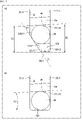
- FIG. 11 (a) in FIG. 11 is an enlarged view of the second inner end surface 32b of the connecting annular portion 30 in FIG. FIG. 11(a) shows the ball 6b when the ball row L is positioned at the second position.
- the ball 6b is the ball 6 located at one end of the ball row L in the axial direction, as described above.
- the axial distance W1 is the axial distance between the other end portion 32b11 and the edge portion 40 of the groove top portion 10a.
- the axial distance W2 is the axial distance between the one end portion 32b12 and the edge portion 40 of the groove top portion 10a.
- the first spiral groove 10 has a lead angle that slopes down to the left in the plane of the paper. Therefore, the axial distance W1 is smaller than the axial distance W2.
- the axial distances W1 and W2 are values based on the edge portion 40 of the groove top portion 10a on the other axial side of the ball 6b. However, if the portion of the spiral track 14 is parallel to the lead angle direction, the portion of the groove top portion 10a other than the edge portion 40 can be used as the reference for the axial distances W1 and W2.
- the angle ⁇ 2 formed by the edge 40 of the groove top portion 10a and the second inner end surface 32b is The lead angle is approximately the same as the lead angle of one spiral groove 10 (helical track 14), which is an extremely acute angle.
- the edge 40 and the second inner end surface 32b form a wedge shape. Therefore, in FIG. 11(b), when the ball 6b moving along the spiral track 14 reaches the second inner end surface 32b, the ball 6b is caught between the edge 40 and the second inner end surface 32b. I'll put it away. If the ball 6b gets caught between the edge portion 40 and the second inner end surface 32b, the ball 6b cannot slide on the spiral track 14, and the function as a sliding screw is impaired.
- the second inner end surface 32b has the inclined surface 32b2, so that the angle ⁇ 1 is less than the angle ⁇ 2 when the second inner end surface 32b does not have the inclined surface 32b2. You can make it bigger. As a result, it is possible to prevent the ball 6b from being bitten, and to prevent the function of the slide screw from being impaired.
- the angle ⁇ 1 is determined by the angle ⁇ formed by the first side surface 22b1 and the inclined surface 32b2. By setting the angle ⁇ to an appropriate angle, the inclined surface 32b2 is provided on the second inner end surface 32b, and the biting of the ball 6b can be suppressed.
- the angle ⁇ 1 is determined by the lead angle of the helical track 14, the coefficient of friction between the balls 6 and the helical track 14, the coefficient of friction between the balls 6 and the retainer 8, and the like.
- the angle ⁇ 1 is 10 degrees or less, there is a high possibility that the ball 6b will get caught. Therefore, it is preferable that the angle ⁇ 1 is 20 degrees or more.
- the angle ⁇ 1 is more preferably 30 degrees or more.
- the circumferential length of the circumferential surface 32b1 (the length between the one end 32b12 and the other end 32b11) is preferably smaller than the diameter of the ball 6b.
- the inclined surface 32b2 can be reliably brought into contact with the ball 6b.
- the first inner end face 32a has the same configuration. That is, since the first inner end surface 32a has the inclined surface 32a2, the groove top portion 10a located on one side in the axial direction with respect to the end ball 6a when the ball row L is at the first position The angle ⁇ 1 formed with the inner end surface 32a can be made relatively large. As a result, when the ball 6a moving along the spiral track 14 reaches the first inner end surface 32a and contacts the inclined surface 32a2, the first spiral groove 10 (the spiral track 14) and the first inner end surface 32a ( It is possible to suppress the ball 6a from being caught between the inclined surface 32a2).
- FIG. 12 is a plan view of the retainer 8 developed.
- an imaginary line D2 on the outer peripheral surface 42 of the retainer 8 passes through the plurality of other end portions 32a12 of the plurality of first inner end surfaces 32a. Therefore, the plurality of first inner end faces 32a are arranged along the imaginary line D2.
- a virtual line D3 on the outer peripheral surface 42 passes through the plurality of one end portions 32b12 of the plurality of second inner end surfaces 32b. Therefore, the plurality of second inner end faces 32b are arranged along the imaginary line D3.
- the virtual line D2 and the virtual line D3 are parallel to the line D1 parallel to the lead angle direction of the spiral track 14 (first spiral groove 10).
- the plurality of first inner end faces 32a and the plurality of second inner end faces 32b are arranged along the lead angle direction of the spiral track 14 (first spiral groove 10). Also, the virtual lines D2 and D3 are parallel to each other. Therefore, the plurality of pockets 32 are arranged so as to be offset along the lead angle direction.
- FIG. 12 shows the case where the ball row L is positioned at the second position. Therefore, the ball 6b at the end of the ball row L is in contact with the inclined surface 32b2 of the second inner end surface 32b.
- the plurality of second inner end surfaces 32b are arranged along the lead angle direction of the spiral track 14, when the ball 6b comes into contact with the inclined surface 32b2, the other balls 6 also come into contact with the same timing as the ball 6b. , abuts on the inclined surface 32b2.
- the plurality of second inner end faces 32b are arranged along the circumferential direction.
- the movement of the ball row L along the spiral track 14 is restricted.
- the force from the screw shaft 2 and the nut 4 concentrates on the ball 6b, and the force from the screw shaft 2 and the nut 4 does not act on the other balls 6 significantly.
- FIG. 12 illustrates the case where the ball row L is positioned at the second position
- the force acting from the screw shaft 2 and the nut 4 can be evenly distributed to the plurality of balls 6, and the biting of the balls 6 can be suppressed more effectively.
- the ball screw device 1 when the screw shaft 2 and the nut 4 rotate relative to each other and the retainer 8 rotates, the ball rows L move within the spiral raceway 14 . Thereby, the ball screw device 1 functions as a ball screw.
- the ball screw device 1 when the ball screw device 1 is operated so as to repeatedly reciprocate the row of balls L, the position of the row of balls L may gradually shift.
- a reference position and a predetermined position different from the reference position are set as relative positions of the screw shaft 2 and the nut 4, and the screw shaft 2 and the nut 4 are reciprocated between the reference position and the predetermined position. explain.
- the ball row L is arranged at the first position when the screw shaft 2 and the nut 4 are at the reference position, and the ball row L is arranged at an intermediate position between the first position and the second position when the screw shaft 2 and the nut 4 are at the predetermined position.
- the ball row L may not return to the first position, or the ball row L may deviate from the intermediate position even though the screw shaft 2 and the nut 4 are in the predetermined positions.
- Such a positional deviation of the ball row L is caused by a difference in load, stroke amount, etc. between the outward and return paths when the ball row L moves in the spiral track 14 .
- Such a difference between the outward path and the return path is caused by the elastic hysteresis of the metal material forming the screw shaft 2 and the nut 4, the shape of the spiral track 14, the lead angle, and the like.
- the biting of the balls 6 described above also contributes to the positional deviation of the row L of balls.
- the retainer 8 prevents the balls 6 from being caught, Limits axial movement along track 14 .
- the balls 6 come into contact with the inclined surface 32a2 of the first inner end surface 32a and the movement of the row of balls L is restricted. be.
- the position of the ball row L is shifted, the movement of the ball row L is restricted by the inclined surface 32a2, and the position of the ball row L is corrected to the first position.
- the retainer 8 restricts the axial movement of the ball rows L along the spiral track 14, even if the ball rows L are misaligned, the misalignment can be corrected. can be done. Further, since it is possible to prevent the ball 6 from being caught when the ball row L reaches the first position or the second position, it is possible to prevent the ball row L from being displaced.
- the retainer 8 included in the ball screw device 1 shown in each of the above embodiments includes an annular portion 20, a plurality of pillars 22, a connecting annular portion 30, and a plurality of pockets 32.
- the portion 20, the plurality of pillars 22, and the connecting annular portion 30 constitute a cylindrical body portion.
- This cylindrical main body is arranged in the annular space K so as to be rotatable around the center line C of the screw shaft 2 and axially immovable relative to the nut 4 .
- the pockets 32 are provided in this body portion, extend along the axial direction, and intersect the spiral track 14 at a plurality of points.
- first and second modifications of the second embodiment the case where the inclined surfaces 32a2 and 32b2 are provided on both the first inner end surface 32a and the second inner end surface 32b is illustrated. At least one of the first inner end surface 32a and the second inner end surface 32b may be provided with an inclined surface.
Landscapes
- Engineering & Computer Science (AREA)
- General Engineering & Computer Science (AREA)
- Mechanical Engineering (AREA)
- Transmission Devices (AREA)
Abstract
ボールねじ装置1は、外周に第1螺旋溝10を有するねじ軸2と、第1螺旋溝10との間で螺旋軌道14を構成する第2螺旋溝12を内周に有するナット4と、螺旋軌道14に配置された複数のボール6を含むボール列Lと、ねじ軸2とナット4との間の環状空間K内に配置され、複数のボール6を保持する保持器8と、を備え、保持器8は、ねじ軸2の中心線C回りに回転可能かつナット4に対して軸方向に相対移動不能に環状空間K内に配置された環状部20と、環状部20の軸方向一方側の一端面20aから軸方向一方側に延び、螺旋軌道14に複数箇所交差する複数の柱22と、複数の柱22のうち周方向に隣り合う一対の柱22の間に設けられ、複数のボール6を転動可能に保持する複数のポケット32と、を備える。
Description
本発明は、ボールねじ装置に関する。
特許文献1には、自動車のブレーキ装置に適用可能なボールねじ装置が開示されている。
このボールねじ装置は、外周に第1螺旋溝を有するねじ軸と、第1螺旋溝との間で螺旋軌道を構成する第2螺旋溝を内周に有するナットと、螺旋軌道に配置された複数のボールからなるボール列とを備える。ねじ軸が回転することにより、ナットがねじ軸の軸方向に沿って移動する。特許文献1に開示のボールねじ装置は、ナットの移動の際、複数のボールが循環する型式の装置ではなく、複数のボールがナットの螺旋軌道内に留まって転動する非循環式の装置である。
このボールねじ装置は、外周に第1螺旋溝を有するねじ軸と、第1螺旋溝との間で螺旋軌道を構成する第2螺旋溝を内周に有するナットと、螺旋軌道に配置された複数のボールからなるボール列とを備える。ねじ軸が回転することにより、ナットがねじ軸の軸方向に沿って移動する。特許文献1に開示のボールねじ装置は、ナットの移動の際、複数のボールが循環する型式の装置ではなく、複数のボールがナットの螺旋軌道内に留まって転動する非循環式の装置である。
上記従来の非循環式のボールねじ装置は、螺旋軌道内に設けられボール列の一端に当接する第1コイルスプリングと、螺旋軌道内に設けられボール列の他端に当接する第2コイルスプリングとを備えている。
上記ボールねじ装置では、ボール列の両端が両コイルスプリングで保持されており、ねじ軸に回転力が与えられナットに対して相対回転すると、両コイルスプリングの伸縮範囲内でボール列が螺旋軌道内を移動し、ナットを軸方向に沿って移動させる。
よって、ボール列の移動を伴うねじ軸のストロークは、コイルスプリングの伸縮量に応じて定まる。
ここで、螺旋軌道内に配置することができるコイルスプリングの伸縮量には限度があり、たとえナットの軸方向の長さをより延ばしたとしても、ボール列の移動を伴うストロークを大きく確保することは困難であった。
上記ボールねじ装置では、ボール列の両端が両コイルスプリングで保持されており、ねじ軸に回転力が与えられナットに対して相対回転すると、両コイルスプリングの伸縮範囲内でボール列が螺旋軌道内を移動し、ナットを軸方向に沿って移動させる。
よって、ボール列の移動を伴うねじ軸のストロークは、コイルスプリングの伸縮量に応じて定まる。
ここで、螺旋軌道内に配置することができるコイルスプリングの伸縮量には限度があり、たとえナットの軸方向の長さをより延ばしたとしても、ボール列の移動を伴うストロークを大きく確保することは困難であった。
実施形態であるボールねじ装置は、外周に第1螺旋溝を有するねじ軸と、前記第1螺旋溝との間で螺旋軌道を構成する第2螺旋溝を内周に有するナットと、前記螺旋軌道に配置された複数のボールを含むボール列と、前記ねじ軸と前記ナットとの間の環状空間内に配置され、前記複数のボールを保持する保持器と、を備える。前記保持器は、前記ねじ軸の中心線回りに回転可能かつ前記ナットに対して軸方向に相対移動不能に前記環状空間内に配置された環状部と、前記環状部の軸方向一方側の一端面から軸方向一方側に延び、前記螺旋軌道に複数箇所交差する複数の柱と、前記複数の柱のうち周方向に隣り合う一対の柱の間に設けられ、前記複数のボールを転動可能に保持する複数のポケットと、を備える。
また、他の観点から見た実施形態であるボールねじ装置は、外周に第1螺旋溝を有するねじ軸と、前記第1螺旋溝との間で螺旋軌道を構成する第2螺旋溝を内周に有するナットと、前記螺旋軌道に配置された複数のボールを含むボール列と、前記ねじ軸と前記ナットとの間の環状空間内に配置され、前記複数のボールを保持する保持器と、を備える。前記保持器は、前記ねじ軸の中心線回りに回転可能かつ前記ナットに対して軸方向に相対移動不能に前記環状空間内に配置された円筒状の本体部と、周方向に沿って前記本体部に設けられ、前記複数のボールを保持する複数のポケットと、を備え、前記複数のポケットは、軸方向に沿って延び前記螺旋軌道に複数箇所交差する。
本開示によれば、ボール列の移動を伴うストロークをより大きく確保することができる。
最初に実施形態の内容を列記して説明する。
[実施形態の概要]
(1)実施形態であるボールねじ装置は、外周に第1螺旋溝を有するねじ軸と、前記第1螺旋溝との間で螺旋軌道を構成する第2螺旋溝を内周に有するナットと、前記螺旋軌道に配置された複数のボールを含むボール列と、前記ねじ軸と前記ナットとの間の環状空間内に配置され、前記複数のボールを保持する保持器と、を備える。前記保持器は、前記ねじ軸の中心線回りに回転可能かつ前記ナットに対して軸方向に相対移動不能に前記環状空間内に配置された環状部と、前記環状部の軸方向一方側の一端面から軸方向一方側に延び、前記螺旋軌道に複数箇所交差する複数の柱と、前記複数の柱のうち周方向に隣り合う一対の柱の間に設けられ、前記複数のボールを転動可能に保持する複数のポケットと、を備える。
[実施形態の概要]
(1)実施形態であるボールねじ装置は、外周に第1螺旋溝を有するねじ軸と、前記第1螺旋溝との間で螺旋軌道を構成する第2螺旋溝を内周に有するナットと、前記螺旋軌道に配置された複数のボールを含むボール列と、前記ねじ軸と前記ナットとの間の環状空間内に配置され、前記複数のボールを保持する保持器と、を備える。前記保持器は、前記ねじ軸の中心線回りに回転可能かつ前記ナットに対して軸方向に相対移動不能に前記環状空間内に配置された環状部と、前記環状部の軸方向一方側の一端面から軸方向一方側に延び、前記螺旋軌道に複数箇所交差する複数の柱と、前記複数の柱のうち周方向に隣り合う一対の柱の間に設けられ、前記複数のボールを転動可能に保持する複数のポケットと、を備える。
上記構成によれば、螺旋軌道に複数箇所交差する柱の間にポケットが設けられるので、ポケットは、軸方向に沿って延び、螺旋軌道に対して複数箇所で交差する。各ボールは、ポケットと螺旋軌道とが交差する箇所に保持される。
ボール列が螺旋軌道内を移動する場合、保持器は、ボール列の移動に応じて回転する。このとき、各ボールは、保持器のポケットに沿って軸方向に移動する。よって、ボール列は、各ボールがポケットに沿って軸方向に移動可能な範囲で螺旋軌道内を移動することができる。
よって、ポケットの軸方向の長さによって、ボール列の移動を伴うストロークを定めることができ、上記従来例のようにコイルスプリングを用いた場合と比較して、ボール列の移動を伴うストロークをより大きく確保することができる。
ボール列が螺旋軌道内を移動する場合、保持器は、ボール列の移動に応じて回転する。このとき、各ボールは、保持器のポケットに沿って軸方向に移動する。よって、ボール列は、各ボールがポケットに沿って軸方向に移動可能な範囲で螺旋軌道内を移動することができる。
よって、ポケットの軸方向の長さによって、ボール列の移動を伴うストロークを定めることができ、上記従来例のようにコイルスプリングを用いた場合と比較して、ボール列の移動を伴うストロークをより大きく確保することができる。
(2)上記ボールねじ装置において、前記保持器は、前記複数の柱の軸方向一方側の先端を連結する連結環状部をさらに備えることが好ましい。
この場合、連結環状部によって保持器の剛性を高めることができる。
この場合、連結環状部によって保持器の剛性を高めることができる。
(3)上記ボールねじ装置において、前記一対の柱の周方向の間隔は、1つの前記ボールを保持可能な間隔とされていてもよい。
この場合、ポケットと螺旋軌道とが交差する箇所には、1つのボールが保持される。
よって、ボールねじ装置を組み立てる際に、各ボールを1つずつポケットと螺旋軌道(第1螺旋溝又は第2螺旋溝)とが交差する箇所に配置すればよく、ポケットと螺旋軌道とが交差する箇所に複数のボールが保持される場合と比較して組み立てが容易となる。
この場合、ポケットと螺旋軌道とが交差する箇所には、1つのボールが保持される。
よって、ボールねじ装置を組み立てる際に、各ボールを1つずつポケットと螺旋軌道(第1螺旋溝又は第2螺旋溝)とが交差する箇所に配置すればよく、ポケットと螺旋軌道とが交差する箇所に複数のボールが保持される場合と比較して組み立てが容易となる。
(4)上記ボールねじ装置において、前記複数のポケットそれぞれには、1つの前記ボールが保持されていることが好ましい。
(5)上記ボールねじ装置において、前記一対の柱の周方向の間隔は、2以上の所定個数の前記ボールを保持可能な間隔とされていてもよい。
この場合、ポケットと螺旋軌道とが交差する箇所には、複数のボールが保持される。
よって、ポケットと螺旋軌道とが交差する箇所に1つのボールが保持される場合と比較して、柱の数を減らすことができる。
この場合、ポケットと螺旋軌道とが交差する箇所には、複数のボールが保持される。
よって、ポケットと螺旋軌道とが交差する箇所に1つのボールが保持される場合と比較して、柱の数を減らすことができる。
(6)上記ボールねじ装置において、前記複数のポケットそれぞれには、前記所定個数の前記ボールが保持されていることが好ましい。
(7)上記ボールねじ装置において、前記ナットと前記環状部との間に設けられ、前記ナットに対する前記保持器の回転に抵抗を付与するフリクション部材を更に備えることが好ましい。
この場合、保持器とナットとがフリクション部材による抵抗によって一体回転可能に保持される程度に、ねじ軸とナットとの間に作用する回転トルクが低い場合、ボールねじ装置は滑りねじとして機能する。一方、フリクション部材による抵抗によって保持器とナットとが一体回転可能に保持できない程度にねじ軸とナットとの間に作用する回転トルクが大きい場合、保持器がねじ軸及びナットに対して回転し、ボールねじとして機能する。
よって、滑りねじとして機能する状態とボールねじとして機能する状態との切り替えをねじ軸とナットとの間に作用する回転トルクに応じて行わせることができる。また、フリクション部材による抵抗を調整すれば、滑りねじとして機能する状態とボールねじとして機能する状態との切り替えのタイミングを調整することができる。
この場合、保持器とナットとがフリクション部材による抵抗によって一体回転可能に保持される程度に、ねじ軸とナットとの間に作用する回転トルクが低い場合、ボールねじ装置は滑りねじとして機能する。一方、フリクション部材による抵抗によって保持器とナットとが一体回転可能に保持できない程度にねじ軸とナットとの間に作用する回転トルクが大きい場合、保持器がねじ軸及びナットに対して回転し、ボールねじとして機能する。
よって、滑りねじとして機能する状態とボールねじとして機能する状態との切り替えをねじ軸とナットとの間に作用する回転トルクに応じて行わせることができる。また、フリクション部材による抵抗を調整すれば、滑りねじとして機能する状態とボールねじとして機能する状態との切り替えのタイミングを調整することができる。
(8)上記ボールねじ装置において、前記フリクション部材は、前記ナットと、前記環状部の外周面との間に介在するゴムリングを含んでいてもよい。
この場合、簡易な構成でナットと環状部との間に摩擦力を生じさせることができ、ナットに対する保持器の回転に抵抗を付与することができる。
この場合、簡易な構成でナットと環状部との間に摩擦力を生じさせることができ、ナットに対する保持器の回転に抵抗を付与することができる。
(9)上記ボールねじ装置において、前記ナットは、径方向内方に前記環状部を収容する円筒内周面と、前記円筒内周面から径方向内方へ延び前記円筒内周面と第2螺旋溝とを繋ぐ段差面と、を有し、前記フリクション部材は、前記環状部を軸方向一方側へ押圧し、前記環状部の前記一端面に対向する前記段差面と、前記一端面とを当接させるウェーブワッシャを含んでいてもよい。
この場合、段差面と、一端面とを当接させ押圧することで、ナットと環状部との間に摩擦力を生じさせることができる。また、ウェーブワッシャの寸法や特性を選択することで、ナットと保持器との間に付与される抵抗を容易に調整することができる。
この場合、段差面と、一端面とを当接させ押圧することで、ナットと環状部との間に摩擦力を生じさせることができる。また、ウェーブワッシャの寸法や特性を選択することで、ナットと保持器との間に付与される抵抗を容易に調整することができる。
(10)上記ボールねじ装置において、前記複数のポケットのそれぞれは、前記一対の柱の側面、及び、前記環状部の第1内端面によって画定され、前記第1内端面は、周方向に沿う第1周方向面と、第1傾斜面とを有し、前記第1周方向面の第1端部は、前記第1周方向面の周方向両端部のうち、前記ポケットを正面視したときの前記第1螺旋溝の溝頂部との軸方向距離が小さい方の端部であり、前記第1傾斜面は、前記一対の柱の側面のうちの前記第1端部側の第1側面と、前記第1端部とを繋ぐように設けられ、前記第1側面から前記第1端部へ向かうにつれて前記一対の柱の側面のうちの第2側面に接近するように傾斜し、前記第1傾斜面は、前記第2側面に接触した状態の前記ボールと接触可能であり、前記ボールが前記第1傾斜面と前記第2側面とに接触したときに、前記第1周方向面は、前記ボールに非接触となる面であることが好ましい。
上記構成では、螺旋軌道に沿って移動するボールが第1内端面に到達したときに、ボールを第1周方向面に接触させずに、第1傾斜面に接触させることができる。
ここで、第1傾斜面は第1側面から第1端部へ向かうにつれて第2側面に接近するように傾斜しているので、ボールに対して軸方向一方側に位置する溝頂部と、第1傾斜面とが成す角度を比較的大きくすることができる。これにより、螺旋軌道と、第1傾斜面との間にボールが噛み込むのを抑制することができる。
よって、螺旋軌道に沿って移動するボールが第1内端面に到達し第1傾斜面に当接したときに、螺旋軌道と、第1傾斜面との間にボールが噛み込むのを抑制することができる。
上記構成では、螺旋軌道に沿って移動するボールが第1内端面に到達したときに、ボールを第1周方向面に接触させずに、第1傾斜面に接触させることができる。
ここで、第1傾斜面は第1側面から第1端部へ向かうにつれて第2側面に接近するように傾斜しているので、ボールに対して軸方向一方側に位置する溝頂部と、第1傾斜面とが成す角度を比較的大きくすることができる。これにより、螺旋軌道と、第1傾斜面との間にボールが噛み込むのを抑制することができる。
よって、螺旋軌道に沿って移動するボールが第1内端面に到達し第1傾斜面に当接したときに、螺旋軌道と、第1傾斜面との間にボールが噛み込むのを抑制することができる。
(11)複数の第1内端面が周方向に沿って並ぶ場合、ボール列の端部に位置するボールが軸方向に移動して第1内端面に到達し、当該ボールが第1端面に当接すると、このボール1つに対してねじ軸及びナットからの力が作用し、他のボールにはねじ軸及びナットからの力が大きく作用しない。
このため、複数の前記第1内端面は、前記第1螺旋溝のリード角方向に沿って並んでいることが好ましい。
この場合、複数のボールを同じタイミングで複数の第1内端面に当接させることができる。この結果、ねじ軸及びナットから作用する力を複数のボールに均等に分散させることができ、ボールの噛み込みをより効果的に抑制することができる。
このため、複数の前記第1内端面は、前記第1螺旋溝のリード角方向に沿って並んでいることが好ましい。
この場合、複数のボールを同じタイミングで複数の第1内端面に当接させることができる。この結果、ねじ軸及びナットから作用する力を複数のボールに均等に分散させることができ、ボールの噛み込みをより効果的に抑制することができる。
(12)上記ボールねじ装置において、前記保持器は、前記複数の柱の軸方向一方側の先端を連結する連結環状部をさらに備え、前記ポケットのそれぞれは、前記一対の柱の側面、前記環状部の第1内端面、及び前記連結環状部の第2内端面によって画定され、前記第2内端面は、周方向に沿う第2周方向面と、第2傾斜面とを有し、前記第2周方向面の第2端部は、前記第2周方向面の周方向両端部のうち、前記ポケットを正面視したときの前記第1螺旋溝の溝頂部との軸方向距離が小さい方の端部であり、前記第2傾斜面は、前記一対の柱の側面のうちの前記第2端部側の第2側面と、前記第2端部とを繋ぐように設けられ、前記第2側面から前記第2端部へ向かうにつれて前記一対の柱の側面のうちの第1側面に接近するように傾斜し、前記第2傾斜面は、前記第1側面に接触した状態の前記ボールと接触可能であり、前記ボールが前記第2傾斜面と前記第1側面とに接触したときに、前記第2周方向面は、前記ボールに非接触となる面であることが好ましい。
上記構成では、螺旋軌道に沿って移動するボールが第2内端面に到達したときに、ボールを第2周方向面に接触させずに、第2傾斜面に接触させることができる。
ここで、第2傾斜面は第2側面から第2端部へ向かうにつれて第1側面に接近するように傾斜しているので、ボールに対して軸方向他方側に位置する溝頂部と、第2傾斜面とが成す角度を比較的大きくすることができる。これにより、螺旋軌道と、第2傾斜面との間にボールが噛み込むのを抑制することができる。
よって、螺旋軌道に沿って移動するボールが第2内端面に到達し第2傾斜面に当接したときに、螺旋軌道と、第2傾斜面との間にボールが噛み込むのを抑制することができる。
上記構成では、螺旋軌道に沿って移動するボールが第2内端面に到達したときに、ボールを第2周方向面に接触させずに、第2傾斜面に接触させることができる。
ここで、第2傾斜面は第2側面から第2端部へ向かうにつれて第1側面に接近するように傾斜しているので、ボールに対して軸方向他方側に位置する溝頂部と、第2傾斜面とが成す角度を比較的大きくすることができる。これにより、螺旋軌道と、第2傾斜面との間にボールが噛み込むのを抑制することができる。
よって、螺旋軌道に沿って移動するボールが第2内端面に到達し第2傾斜面に当接したときに、螺旋軌道と、第2傾斜面との間にボールが噛み込むのを抑制することができる。
(13)上記ボールねじ装置において、複数の前記第2内端面は、前記第1螺旋溝のリード角方向に沿って並んでいることが好ましい。
この場合、複数のボールを同じタイミングで複数の第2内端面に当接させることができる。この結果、ねじ軸及びナットから作用する力を複数のボールに均等に分散させることができ、ボールの噛み込みを効果的に抑制することができる。
この場合、複数のボールを同じタイミングで複数の第2内端面に当接させることができる。この結果、ねじ軸及びナットから作用する力を複数のボールに均等に分散させることができ、ボールの噛み込みを効果的に抑制することができる。
(14)他の観点から見た実施形態であるボールねじ装置は、外周に第1螺旋溝を有するねじ軸と、前記第1螺旋溝との間で螺旋軌道を構成する第2螺旋溝を内周に有するナットと、前記螺旋軌道に配置された複数のボールを含むボール列と、前記ねじ軸と前記ナットとの間の環状空間内に配置され、前記複数のボールを保持する保持器と、を備える。前記保持器は、前記ねじ軸の中心線回りに回転可能かつ前記ナットに対して軸方向に相対移動不能に前記環状空間内に配置された円筒状の本体部と、周方向に沿って前記本体部に設けられ、前記複数のボールを保持する複数のポケットと、を備える。前記複数のポケットは、軸方向に沿って延び前記螺旋軌道に複数箇所交差する。
[実施形態の詳細]
以下、好ましい実施形態について図面を参照しつつ説明する。
〔第1実施形態について〕
図1は、第1実施形態に係るボールねじ装置の斜視図、図2は、ボールねじ装置の断面図である。なお、図2はボールねじ装置の中心線を含む平面に沿った断面図である。
このボールねじ装置1は、自動車等の車両のブレーキ装置や、多板クラッチを含む動力伝達装置等に用いられる。
ボールねじ装置1は、ねじ軸2と、ねじ軸2の外周側に設けられたナット4と、複数のボール6と、複数のボール6を保持する保持器8とを備える。
本実施形態では、ねじ軸2の中心線Cに平行な方向を軸方向と定義し、中心線Cに直交する方向を径方向と定義し、中心線Cを中心とする円に沿う方向を周方向と定義する。
また、図1及び図2中、軸方向においてナット4の開口に止め輪9が設けられていない側を軸方向一方側と定義し、止め輪9が設けられている側を軸方向他方側と定義する。
以下、好ましい実施形態について図面を参照しつつ説明する。
〔第1実施形態について〕
図1は、第1実施形態に係るボールねじ装置の斜視図、図2は、ボールねじ装置の断面図である。なお、図2はボールねじ装置の中心線を含む平面に沿った断面図である。
このボールねじ装置1は、自動車等の車両のブレーキ装置や、多板クラッチを含む動力伝達装置等に用いられる。
ボールねじ装置1は、ねじ軸2と、ねじ軸2の外周側に設けられたナット4と、複数のボール6と、複数のボール6を保持する保持器8とを備える。
本実施形態では、ねじ軸2の中心線Cに平行な方向を軸方向と定義し、中心線Cに直交する方向を径方向と定義し、中心線Cを中心とする円に沿う方向を周方向と定義する。
また、図1及び図2中、軸方向においてナット4の開口に止め輪9が設けられていない側を軸方向一方側と定義し、止め輪9が設けられている側を軸方向他方側と定義する。
ねじ軸2は、ナット4に挿通されており、外周に第1螺旋溝10を有する。
ナット4は、円筒状の部材である。ナット4の中心線は中心線Cに一致している。ナット4は、内周に第2螺旋溝12を有する。また、ナット4の内周における軸方向他方側の端部には円筒内周面4aが設けられている。
ねじ軸2の第1螺旋溝10と、ナット4の第2螺旋溝12とは、複数のボール6が配置される螺旋軌道14を構成する。
また、第1螺旋溝10の溝頂部10aの外径寸法は、第2螺旋溝12の溝頂部12aの内径寸法よりも小さい。よって、ねじ軸2と、ナット4との間には、環状空間Kが設けられる。
ナット4は、円筒状の部材である。ナット4の中心線は中心線Cに一致している。ナット4は、内周に第2螺旋溝12を有する。また、ナット4の内周における軸方向他方側の端部には円筒内周面4aが設けられている。
ねじ軸2の第1螺旋溝10と、ナット4の第2螺旋溝12とは、複数のボール6が配置される螺旋軌道14を構成する。
また、第1螺旋溝10の溝頂部10aの外径寸法は、第2螺旋溝12の溝頂部12aの内径寸法よりも小さい。よって、ねじ軸2と、ナット4との間には、環状空間Kが設けられる。
保持器8は、ねじ軸2とナット4との間の環状空間K内に配置されている。
保持器8は、環状部20と、複数の柱22とを備える。
環状部20は、円筒内周面4aの径方向内方に収容されている。環状部20は、円筒内周面4aとねじ軸2との間に配置されている。
円筒内周面4aには、止め輪9が嵌め込まれている環状溝4bが設けられている。
環状部20の軸方向一方側の一端面20aは、ナット4の段差面24に対向している。段差面24は、円筒内周面4aから径方向内方へ延び、円筒内周面4aと第2螺旋溝12との間を繋いでいる面である。
また、環状部20の軸方向他方側の他端面20bは、止め輪9の内側面9aに対向している。
保持器8は、環状部20と、複数の柱22とを備える。
環状部20は、円筒内周面4aの径方向内方に収容されている。環状部20は、円筒内周面4aとねじ軸2との間に配置されている。
円筒内周面4aには、止め輪9が嵌め込まれている環状溝4bが設けられている。
環状部20の軸方向一方側の一端面20aは、ナット4の段差面24に対向している。段差面24は、円筒内周面4aから径方向内方へ延び、円筒内周面4aと第2螺旋溝12との間を繋いでいる面である。
また、環状部20の軸方向他方側の他端面20bは、止め輪9の内側面9aに対向している。
また、環状部20の内周面20cと、ねじ軸2の第1螺旋溝10の溝頂部10aとの間には、僅かなクリアランスが設けられている。また、環状部20の外周面20dと、円筒内周面4aとの間にも僅かなクリアランスが設けられている。
これにより、環状部20は、中心線C回りに回転可能かつナット4に対して軸方向に相対移動不能に環状空間K内に配置されている。
これにより、環状部20は、中心線C回りに回転可能かつナット4に対して軸方向に相対移動不能に環状空間K内に配置されている。
環状部20の外周面20dには、外周溝20d1が設けられている。外周溝20d1には、フリクション部材26が設けられている。
本実施形態では、フリクション部材26は、ゴムリングである。フリクション部材26は、外周溝20d1に嵌め込まれている。
フリクション部材26は、円筒内周面4aと、外周溝20d1との間に介在し、円筒内周面4aと外周溝20d1とに接触している。つまり、フリクション部材26は、ナット4と環状部20との間に設けられている。フリクション部材26は、円筒内周面4a及び外周溝20d1に接触することにより生じる摩擦力によってナット4に対する保持器8の回転に抵抗を付与する。
よって、ナット4と保持器8との間に作用する相対回転させようとする力がフリクション部材26による抵抗よりも小さければ、保持器8はナット4とともに一体回転し、相対回転させようとする力がフリクション部材26による抵抗よりも大きければ、保持器8はナット4に対して相対回転可能となる。
本実施形態では、フリクション部材26は、ゴムリングである。フリクション部材26は、外周溝20d1に嵌め込まれている。
フリクション部材26は、円筒内周面4aと、外周溝20d1との間に介在し、円筒内周面4aと外周溝20d1とに接触している。つまり、フリクション部材26は、ナット4と環状部20との間に設けられている。フリクション部材26は、円筒内周面4a及び外周溝20d1に接触することにより生じる摩擦力によってナット4に対する保持器8の回転に抵抗を付与する。
よって、ナット4と保持器8との間に作用する相対回転させようとする力がフリクション部材26による抵抗よりも小さければ、保持器8はナット4とともに一体回転し、相対回転させようとする力がフリクション部材26による抵抗よりも大きければ、保持器8はナット4に対して相対回転可能となる。
保持器8が有する複数の柱22は、環状部20の一端面20aから軸方向一方側に延びている。本実施形態の保持器8は、3つの柱22を備える。3つの柱22は、周方向に等間隔に配置されている。
図3(a)は、ねじ軸2の外周側に配置された状態の保持器8を示す斜視図、図3(b)は、保持器8を示す斜視図である。
図2及び図3に示すように、3つの柱22は、ねじ軸2の第1螺旋溝10の溝頂部10aと、ナット4の第2螺旋溝12の溝頂部12aとの間を横切るように軸方向に延びており、螺旋軌道14に複数箇所交差している。
図2及び図3に示すように、3つの柱22は、ねじ軸2の第1螺旋溝10の溝頂部10aと、ナット4の第2螺旋溝12の溝頂部12aとの間を横切るように軸方向に延びており、螺旋軌道14に複数箇所交差している。
また、保持器8は、柱22の軸方向一方側の先端22aを連結する連結環状部30を備える。連結環状部30の中心線は中心線Cと一致しており、環状部20と同心とされている。連結環状部30の軸方向一方側の一端面30aは、ナット4の軸方向一方側の端面4cとほぼ一致している。このように連結環状部30はナット4の軸方向一方側の端部に設けられている。
保持器8は、さらに、複数のボール6を転動可能に保持する複数のポケット32を備える。
ポケット32は、3つの柱22のうち周方向に隣り合う一対の柱22の間に設けられている。よって、本実施形態の保持器8は、3つのポケット32を備える。
ポケット32は、周方向に隣り合う一対の柱22と、環状部20と、連結環状部30とで囲まれた矩形状の空間である。
よって、ポケット32は、軸方向に沿って延び、螺旋軌道14に対して複数箇所で交差する。
ポケット32は、3つの柱22のうち周方向に隣り合う一対の柱22の間に設けられている。よって、本実施形態の保持器8は、3つのポケット32を備える。
ポケット32は、周方向に隣り合う一対の柱22と、環状部20と、連結環状部30とで囲まれた矩形状の空間である。
よって、ポケット32は、軸方向に沿って延び、螺旋軌道14に対して複数箇所で交差する。
ポケット32は、周方向に隣り合う一対の柱22の側面22b、環状部20の第1内端面32a、及び連結環状部30の第2内端面32bによって画定される。
第1内端面32aは、環状部20の軸方向一方側の端面である。第2内端面32bは、連結環状部30の軸方向他方側の端面である。
一対の側面22bは、軸方向に沿っている。第1内端面32a及び第2内端面32bは周方向に沿っている。
周方向に隣り合う一対の柱22の周方向の間隔は、図4(a)、図4(b)に示すように、2つのボール6を保持可能な間隔とされている。
第1内端面32aは、環状部20の軸方向一方側の端面である。第2内端面32bは、連結環状部30の軸方向他方側の端面である。
一対の側面22bは、軸方向に沿っている。第1内端面32a及び第2内端面32bは周方向に沿っている。
周方向に隣り合う一対の柱22の周方向の間隔は、図4(a)、図4(b)に示すように、2つのボール6を保持可能な間隔とされている。
複数のボール6は、螺旋軌道14内に配置されボール列Lを構成する。なお、本実施形態では、ボール列Lは6つのボール6を含む。
上述のように、周方向に隣り合う一対の柱22の周方向の間隔は、2つのボール6を保持可能な間隔である。よって、ボール列Lには、3つの柱22が介在している。3つの柱22は、列長手方向に並ぶボール列Lのボール6を3つに分けるように介在する。
つまり、3つのポケット32は、それぞれ、列長手方向に並ぶ2つのボール6を保持する。
上述のように、周方向に隣り合う一対の柱22の周方向の間隔は、2つのボール6を保持可能な間隔である。よって、ボール列Lには、3つの柱22が介在している。3つの柱22は、列長手方向に並ぶボール列Lのボール6を3つに分けるように介在する。
つまり、3つのポケット32は、それぞれ、列長手方向に並ぶ2つのボール6を保持する。
ボール列Lは、ねじ軸2がナット4に対して相対回転し、さらに、保持器8が中心線C回りに回転すると、螺旋軌道14内を移動する。ボール列Lが螺旋軌道14内を移動することで、ボールねじ装置1は、ボールねじとして機能する。
ここで、ボール6は、ポケット32に保持されているので、ボール列Lの軸方向における移動範囲は、保持器8によって制限される。
ここで、ボール6は、ポケット32に保持されているので、ボール列Lの軸方向における移動範囲は、保持器8によって制限される。
例えば、図4(a)に示すように、6つのボール6のうち、ボール列Lにおける軸方向他方側の端部に位置するボール6aが環状部20の第1内端面32a及び柱22の側面22bに当接しているときに、保持器8におけるボール列Lの軸方向位置は、最も軸方向他方側寄りの位置(第1位置)となる。
なお、図4(a)及び図4(b)では、理解容易のため、ナット4を省略して示している。
なお、図4(a)及び図4(b)では、理解容易のため、ナット4を省略して示している。
ねじ軸2をナット4に対して相対回転させ、第1位置のボール列Lを軸方向一方側へ向けて移動させると、図4(b)に示すように、6つのボール6のうち、ボール列Lにおける軸方向一方側の端部に位置するボール6bが連結環状部30の第2内端面32b、及び柱22の側面22bに当接する。ボール6bは、連結環状部30及び柱22によって、それ以上螺旋軌道14に沿った軸方向一方側への移動が制限される。よって、図4(b)に示すように、ボール6bが連結環状部30及び柱22に当接しているときに、保持器8におけるボール列Lの軸方向位置は、保持器8内において最も軸方向一方側寄りの位置(第2位置)となる。
このように、ボール列Lの軸方向における移動範囲は、保持器8によって制限される。
このように、ボール列Lの軸方向における移動範囲は、保持器8によって制限される。
ボールねじ装置1は、ねじ軸2をナット4に対して相対回転させ、ボール列Lが第1位置から第2位置へ移動する間、ボールねじとして機能する。
ボール列Lが第1位置から第2位置へ到達した後、さらにねじ軸2をナット4に対して相対回転させた場合、ボール列Lの軸方向への移動が制限されるので、ボールねじ装置1は、ボールねじとして機能せず、滑りねじとして機能する。
逆に、ボール列Lが第2位置から第1位置へ移動する間も、ボールねじ装置1は、ボールねじとして機能する。
ボール列Lが第2位置から第1位置へ到達した後、さらにねじ軸2をナット4に対して相対回転させた場合、この場合もボール列Lの軸方向への移動が制限されるので、ボールねじ装置1は、ボールねじとして機能せず、滑りねじとして機能する。
ボール列Lが第1位置から第2位置へ到達した後、さらにねじ軸2をナット4に対して相対回転させた場合、ボール列Lの軸方向への移動が制限されるので、ボールねじ装置1は、ボールねじとして機能せず、滑りねじとして機能する。
逆に、ボール列Lが第2位置から第1位置へ移動する間も、ボールねじ装置1は、ボールねじとして機能する。
ボール列Lが第2位置から第1位置へ到達した後、さらにねじ軸2をナット4に対して相対回転させた場合、この場合もボール列Lの軸方向への移動が制限されるので、ボールねじ装置1は、ボールねじとして機能せず、滑りねじとして機能する。
このように、ボールねじ装置1は、ねじ軸2をナット4に対して相対回転させ、ボール列Lが保持器8における第1位置と第2位置との間を移動する間、ボールねじとして機能する。一方、ボール列Lが移動しない場合には、ボールねじ装置1は、滑りねじとして機能する。
上記構成のボールねじ装置1は、ねじ軸2に回転力を与え、ねじ軸2をナット4に対して相対回転させることで、ナットを軸方向に沿って移動させ、ねじ軸2に与えられる回転運動を直線運動に変換する用途に用いられる。
ねじ軸2がナット4に対して相対回転する際、上述のように、ボール列Lが螺旋軌道14内を移動すれば、ボールねじ装置1は、ボールねじとして機能し、ねじ軸2に伝達する回転力を減速した上でナット4を軸方向へ移動させる。つまり、ボールねじ装置1のストロークのうち、ボール列Lが第1位置と第2位置との間を移動する間、ねじ軸2に与えられる回転力が減速される。
一方、ボール列Lが螺旋軌道14内を移動しない場合には、ボールねじ装置1は、滑りねじとして機能し、ねじ軸2に与えられる回転に応じてナット4を軸方向へ移動させる。
ねじ軸2がナット4に対して相対回転する際、上述のように、ボール列Lが螺旋軌道14内を移動すれば、ボールねじ装置1は、ボールねじとして機能し、ねじ軸2に伝達する回転力を減速した上でナット4を軸方向へ移動させる。つまり、ボールねじ装置1のストロークのうち、ボール列Lが第1位置と第2位置との間を移動する間、ねじ軸2に与えられる回転力が減速される。
一方、ボール列Lが螺旋軌道14内を移動しない場合には、ボールねじ装置1は、滑りねじとして機能し、ねじ軸2に与えられる回転に応じてナット4を軸方向へ移動させる。
上記構成によれば、螺旋軌道14に複数箇所交差する柱22の間にポケット32が設けられるので、ポケット32は、軸方向に沿って延び、螺旋軌道14に対して複数箇所で交差する。各ボール6は、ポケット32と螺旋軌道14とが交差する箇所に保持される。
ボール列Lが螺旋軌道14内を移動する場合、保持器8は、ボール列Lの移動に応じて回転する。このとき、各ボール6は、保持器8のポケット32に沿って軸方向に移動する。よって、ボール列Lは、各ボール6がポケット32に沿って軸方向に移動可能な範囲で螺旋軌道14内を移動することができる。
よって、ポケット32の軸方向の長さによって、ボール列Lの移動を伴うストロークを定めることができ、上記従来例のようにコイルスプリングを用いた場合と比較して、ボール列の移動を伴うストロークをより大きく確保することができる。
ボール列Lが螺旋軌道14内を移動する場合、保持器8は、ボール列Lの移動に応じて回転する。このとき、各ボール6は、保持器8のポケット32に沿って軸方向に移動する。よって、ボール列Lは、各ボール6がポケット32に沿って軸方向に移動可能な範囲で螺旋軌道14内を移動することができる。
よって、ポケット32の軸方向の長さによって、ボール列Lの移動を伴うストロークを定めることができ、上記従来例のようにコイルスプリングを用いた場合と比較して、ボール列の移動を伴うストロークをより大きく確保することができる。
また、本実施形態では、ナット4と保持器8の環状部20との間にフリクション部材26が設けられているので、ボールねじ装置1を滑りねじとして機能する状態とボールねじとして機能する状態との切り替えのタイミングを調整することができる。
例えば、図4(a)に示す状態から、ナット4を軸方向他方側へ移動させようとねじ軸2とナット4とを相対回転させたときに、ねじ軸2とナット4との間に作用する回転トルクが比較的小さい場合、フリクション部材26は、ナット4及び環状部20に接触することにより生じる抵抗によって保持器8をナット4に対して一体回転可能に保持する。
保持器8がナット4に対して相対回転しない場合、ボール列Lは螺旋軌道14内を移動しないので、ボールねじ装置1は、滑りねじとして機能する。
例えば、図4(a)に示す状態から、ナット4を軸方向他方側へ移動させようとねじ軸2とナット4とを相対回転させたときに、ねじ軸2とナット4との間に作用する回転トルクが比較的小さい場合、フリクション部材26は、ナット4及び環状部20に接触することにより生じる抵抗によって保持器8をナット4に対して一体回転可能に保持する。
保持器8がナット4に対して相対回転しない場合、ボール列Lは螺旋軌道14内を移動しないので、ボールねじ装置1は、滑りねじとして機能する。
一方、ねじ軸2とナット4との間に作用する回転トルクが比較的大きく、ナット4と保持器8との間に作用する相対回転させようとする力がフリクション部材26による抵抗よりも大きくなると、ナット4に対する保持器8の相対回転が許容される。
この場合、ボール列Lは螺旋軌道14内を移動可能となるので、ボールねじ装置1は、ボールねじとして機能する。
この場合、ボール列Lは螺旋軌道14内を移動可能となるので、ボールねじ装置1は、ボールねじとして機能する。
このように、本実施形態では、ナット4と保持器8の環状部20との間にフリクション部材26が設けられているので、滑りねじとして機能する状態とボールねじとして機能する状態との切り替えをねじ軸2とナット4との間に作用する回転トルクに応じて行わせることができる。
また、フリクション部材26による抵抗を調整すれば、滑りねじとして機能する状態とボールねじとして機能する状態との切り替えのタイミングを調整することができる。
本実施形態では、フリクション部材26をゴムリングで構成したので、簡易な構成でナット4と環状部20との間に摩擦力を生じさせることができ、ナット4に対する保持器8の回転に抵抗を付与することができる。
また、フリクション部材26による抵抗を調整すれば、滑りねじとして機能する状態とボールねじとして機能する状態との切り替えのタイミングを調整することができる。
本実施形態では、フリクション部材26をゴムリングで構成したので、簡易な構成でナット4と環状部20との間に摩擦力を生じさせることができ、ナット4に対する保持器8の回転に抵抗を付与することができる。
また、本実施形態では、保持器8が柱22の先端22aに連結環状部30を備えるので、保持器8の剛性を高めることができる。
また、連結環状部30を設けることで、ボール列Lの軸方向位置が第1位置であるときのボール列Lにおける軸方向一方側の端部のボール6bがさらに軸方向一方側へ移動するのをより強固に制限することができる。
また、連結環状部30を設けることで、ボール列Lの軸方向位置が第1位置であるときのボール列Lにおける軸方向一方側の端部のボール6bがさらに軸方向一方側へ移動するのをより強固に制限することができる。
また、本実施形態では、周方向に隣り合う一対の柱22の周方向の間隔が、2つのボール6を保持可能な間隔とされているので、ポケット32と螺旋軌道14とが交差する箇所には、2つのボール6が保持される。
よって、ポケット32と螺旋軌道14とが交差する箇所に1つのボール6が保持される場合と比較して柱22の数を減らすことができる。
よって、ポケット32と螺旋軌道14とが交差する箇所に1つのボール6が保持される場合と比較して柱22の数を減らすことができる。
図5は、第1実施形態の変形例に係るボールねじ装置1の要部断面図である。
上記実施形態では、フリクション部材26をゴムリングによって構成した場合を示したが、本変形例では、フリクション部材26をウェーブワッシャによって構成した場合を示している。
本実施形態のフリクション部材26は、環状部20の他端面20bと、止め輪9の内側面9aのとの間に介在し、環状部20(保持器8)を軸方向一方側へ押圧する。
これにより、フリクション部材26は、ナット4の段差面24と、環状部20の一端面20aとを当接させ、段差面24と、一端面20aとの間の摩擦力によってナット4に対する保持器8の回転に抵抗を付与する。
上記実施形態では、フリクション部材26をゴムリングによって構成した場合を示したが、本変形例では、フリクション部材26をウェーブワッシャによって構成した場合を示している。
本実施形態のフリクション部材26は、環状部20の他端面20bと、止め輪9の内側面9aのとの間に介在し、環状部20(保持器8)を軸方向一方側へ押圧する。
これにより、フリクション部材26は、ナット4の段差面24と、環状部20の一端面20aとを当接させ、段差面24と、一端面20aとの間の摩擦力によってナット4に対する保持器8の回転に抵抗を付与する。
本変形例では、段差面24と、一端面20aとを当接させ押圧することで、ナット4と環状部20との間に摩擦力を生じさせることができる。また、ウェーブワッシャであるフリクション部材26の寸法や特性を選択することで、段差面24と、一端面20aとの間の摩擦力を容易に調整することができ、ナット4と保持器8との間に付与される抵抗を容易に調整することができる。この結果、滑りねじとして機能する状態とボールねじとして機能する状態との切り替えのタイミングを容易に調整することができる。
〔第2実施形態について〕
図6は、第2実施形態に係るボールねじ装置1の分解斜視図、図7は、第2実施形態に係るボールねじ装置1の要部断面図である。なお、図6、及び図7では、ボール6を省略して示している。
図6は、第2実施形態に係るボールねじ装置1の分解斜視図、図7は、第2実施形態に係るボールねじ装置1の要部断面図である。なお、図6、及び図7では、ボール6を省略して示している。
本実施形態のボールねじ装置1も、第1実施形態と同様、外周に第1螺旋溝10を有するねじ軸2と、第1螺旋溝10との間で螺旋軌道14を構成する第2螺旋溝12を内周に有するナット4と、螺旋軌道14に配置された複数のボール6を含むボール列Lと、ねじ軸2とナット4との間の環状空間K内に配置され、複数のボール6を保持する保持器8とを備える。
また、保持器8は、ねじ軸2の中心線C回りに回転可能かつナット4に対して軸方向に相対移動不能に環状空間K内に配置された環状部20と、環状部20の軸方向一方側の一端面20aから軸方向一方側に延び、螺旋軌道14に複数箇所交差する複数の柱22と、複数の柱22の先端を連結する連結環状部30と、複数の柱22のうち周方向に隣り合う一対の柱の間に設けられ、複数のボール6を転動可能に保持する複数のポケット32とを備える。
また、保持器8は、ねじ軸2の中心線C回りに回転可能かつナット4に対して軸方向に相対移動不能に環状空間K内に配置された環状部20と、環状部20の軸方向一方側の一端面20aから軸方向一方側に延び、螺旋軌道14に複数箇所交差する複数の柱22と、複数の柱22の先端を連結する連結環状部30と、複数の柱22のうち周方向に隣り合う一対の柱の間に設けられ、複数のボール6を転動可能に保持する複数のポケット32とを備える。
本実施形態は、保持器8の軸方向他方側に配置されるスリーブ36を有する点、及び、周方向に隣り合う一対の柱22の周方向の間隔が1つのボール6を保持可能な間隔とされている点において、第1実施形態と相違する。
スリーブ36は、ねじ軸2の外周側に配置され、ナット4の円筒内周面4aに内嵌固定されている。
スリーブ36の軸方向一方側の一端面36aは、環状部20の他端面20bに当接している。これにより、環状部20は、ナット4の段差面24と、スリーブ36の一端面36aとによって、ナット4に対して軸方向に相対移動不能とされる。
スリーブ36の軸方向一方側の一端面36aは、環状部20の他端面20bに当接している。これにより、環状部20は、ナット4の段差面24と、スリーブ36の一端面36aとによって、ナット4に対して軸方向に相対移動不能とされる。
図8は、ねじ軸2の外周側に配置された状態の保持器8を示す図である。
本実施形態の保持器8は、14本の柱22を有している。よって、保持器8は、14個のポケット32を有する。
本実施形態のボール列Lは、例えば、14個のボール6を含んでいる。よって、各ポケット32は、それぞれ1つのボール6を保持する。
この場合、ポケット32と螺旋軌道14とが交差する箇所には、1つのボール6が保持される。
よって、ボールねじ装置1を組み立てる際に、各ボール6を1つずつポケット32と螺旋軌道14(第1螺旋溝10又は第2螺旋溝12)とが交差する箇所に配置すればよく、ポケット32と螺旋軌道14とが交差する箇所に複数のボール6が保持される場合と比較して組み立てが容易となる。
本実施形態の保持器8は、14本の柱22を有している。よって、保持器8は、14個のポケット32を有する。
本実施形態のボール列Lは、例えば、14個のボール6を含んでいる。よって、各ポケット32は、それぞれ1つのボール6を保持する。
この場合、ポケット32と螺旋軌道14とが交差する箇所には、1つのボール6が保持される。
よって、ボールねじ装置1を組み立てる際に、各ボール6を1つずつポケット32と螺旋軌道14(第1螺旋溝10又は第2螺旋溝12)とが交差する箇所に配置すればよく、ポケット32と螺旋軌道14とが交差する箇所に複数のボール6が保持される場合と比較して組み立てが容易となる。
図9は、第2実施形態の第1変形例に係るボールねじ装置1の保持器8を示す図である。
この第1変形例では、環状部20の第1内端面32aが、周方向に沿う周方向面32a1と、周方向面32a1に対して傾斜する傾斜面32a2とを含んで構成されている点、及び、連結環状部30の第2内端面32bが、周方向に沿う周方向面32b1と、周方向面32b1に対して傾斜する傾斜面32b2とを含んで構成されている点において第2実施形態と相違する。
この第1変形例では、環状部20の第1内端面32aが、周方向に沿う周方向面32a1と、周方向面32a1に対して傾斜する傾斜面32a2とを含んで構成されている点、及び、連結環状部30の第2内端面32bが、周方向に沿う周方向面32b1と、周方向面32b1に対して傾斜する傾斜面32b2とを含んで構成されている点において第2実施形態と相違する。
図9に示すように、周方向面32a1の周方向両端部のうち、ポケット32を正面視したときに溝頂部10aとの軸方向距離が小さい方の一端部32a11側に傾斜面32a2が設けられている。一端部32a11は、周方向面32a1の周方向両端部のうちの周方向一方側の端部である。
傾斜面32a2は、周方向面32a1の一端部32a11と、柱22の側面22bとを繋ぐように設けられている。傾斜面32a2は、一端部32a11から柱22の側面22b側に向かって軸方向一方側へ傾斜している。よって、傾斜面32a2と側面22bとがなす角度は90度以上となっている。
傾斜面32a2は、周方向面32a1の一端部32a11と、柱22の側面22bとを繋ぐように設けられている。傾斜面32a2は、一端部32a11から柱22の側面22b側に向かって軸方向一方側へ傾斜している。よって、傾斜面32a2と側面22bとがなす角度は90度以上となっている。
ボール列Lの軸方向位置が第1位置に位置し、ボール列Lにおける軸方向他方側の端部に位置するボール6aが第1内端面32a及び柱22の側面22bに当接するときに、ボール6aは、柱22の側面22bと、第1内端面32aの傾斜面32a2とに当接する。
このとき、傾斜面32a2と側面22bとがなす角度が90度以上となっているのでボール6aが傾斜面32a2と側面22bとの間に噛み込むのを抑制することができる。
このとき、傾斜面32a2と側面22bとがなす角度が90度以上となっているのでボール6aが傾斜面32a2と側面22bとの間に噛み込むのを抑制することができる。
同様に、第2内端面32bにおける周方向面32b1の周方向両端部のうち、ポケット32を正面視したときに溝頂部10aとの軸方向距離が小さい方の他端部32b11側に傾斜面32b2が設けられている。他端部32b11は、周方向面32b1の周方向両端部のうちの周方向他方側の端部である。
傾斜面32b2は、周方向面32b1の他端部32b11と、柱22の側面22bとを繋ぐように設けられている。傾斜面32b2は、他端部32b11から側面22b側に向かって軸方向他方側へ傾斜している。よって、傾斜面32b2と側面22bとがなす角度は90度以上となっている。
傾斜面32b2は、周方向面32b1の他端部32b11と、柱22の側面22bとを繋ぐように設けられている。傾斜面32b2は、他端部32b11から側面22b側に向かって軸方向他方側へ傾斜している。よって、傾斜面32b2と側面22bとがなす角度は90度以上となっている。
ボール列Lの軸方向位置が第2位置に位置し、ボール列Lにおける軸方向一方側の端部に位置するボール6bが第2内端面32b及び柱22の側面22bに当接するときに、ボール6bは、柱22の側面22bと、第2内端面32bの傾斜面32b2とに当接する。
このとき、傾斜面32b2と側面22bとがなす角度が90度以上となっているのでボール6bが傾斜面32b2と側面22bとの間に噛み込むのを抑制することができる。
このとき、傾斜面32b2と側面22bとがなす角度が90度以上となっているのでボール6bが傾斜面32b2と側面22bとの間に噛み込むのを抑制することができる。
図10は、第2実施形態の第2変形例に係るボールねじ装置1の保持器8を示す図である。
この第2変形例は、複数の第1内端面32a及び複数の第2内端面32bが、螺旋軌道14(第1螺旋溝10)のリード角方向に沿って並んでいる点において第1変型例と相違する。
この第2変形例は、複数の第1内端面32a及び複数の第2内端面32bが、螺旋軌道14(第1螺旋溝10)のリード角方向に沿って並んでいる点において第1変型例と相違する。
本変形例においても、第1変形例と同様、環状部20の第1内端面32aが、周方向に沿う周方向面32a1と、傾斜面32a2とを含んで構成されており、連結環状部30の第2内端面32bが、周方向に沿う周方向面32b1と、傾斜面32b2とを含んで構成されている。
図10中、一端部32a11(第1端部)は、周方向面32a1(第1周方向面)の周方向一方側の端部である。他端部32a12は、周方向面32a1の周方向他方側の端部である。
ポケット32を正面視したときの一端部32a11と溝頂部10aとの軸方向距離は、他端部32a12と溝頂部10aとの軸方向距離よりも小さい。
つまり、周方向面32a1の一端部32a11は、周方向面32a1の両端部のうち、ポケット32を正面視したときの溝頂部10aとの軸方向距離が小さい方の端部である。
ポケット32を正面視したときの一端部32a11と溝頂部10aとの軸方向距離は、他端部32a12と溝頂部10aとの軸方向距離よりも小さい。
つまり、周方向面32a1の一端部32a11は、周方向面32a1の両端部のうち、ポケット32を正面視したときの溝頂部10aとの軸方向距離が小さい方の端部である。
傾斜面32a2(第1傾斜面)は、第1側面22b1と、一端部32a11とを繋ぐように設けられている。傾斜面32a2は、第1側面22b1の端部22b11と、一端部32a11とを繋ぐ。
また、傾斜面32a2は、第1側面22b1から一端部32a11へ向かうにつれて第2側面22b2に接近するように傾斜している。
第1側面22b1は、ポケット32を画定する一対の柱22の側面22bのうちの一端部32a11側の側面22bである。また、第2側面22b2は、一対の柱22の側面22bのうちのもう一方の側面である。
傾斜面32a2と第1側面22b1とがなす角度は90度以上となっている。
また、傾斜面32a2は、第1側面22b1から一端部32a11へ向かうにつれて第2側面22b2に接近するように傾斜している。
第1側面22b1は、ポケット32を画定する一対の柱22の側面22bのうちの一端部32a11側の側面22bである。また、第2側面22b2は、一対の柱22の側面22bのうちのもう一方の側面である。
傾斜面32a2と第1側面22b1とがなす角度は90度以上となっている。
傾斜面32a2は、第2側面22b2に接触した状態のボール6と接触可能である。また、ボール6が傾斜面32a2と第2側面22b2とに接触したときに、周方向面32a1は、ボール6に非接触となる面である。
図10中、ポケット32を正面視したときの他端部32b11と溝頂部10aとの軸方向距離は、一端部32b12と溝頂部10aとの軸方向距離よりも小さい。
一端部32b12は、周方向面32b1の周方向一方側の端部である。他端部32b11(第2端部)は、周方向面32b1(第2周方向面)の周方向他方側の端部である。
つまり、周方向面32b1の他端部32b11は、周方向面32b1の両端部のうち、ポケット32を正面視したときの溝頂部10aとの軸方向距離が小さい方の端部である。
一端部32b12は、周方向面32b1の周方向一方側の端部である。他端部32b11(第2端部)は、周方向面32b1(第2周方向面)の周方向他方側の端部である。
つまり、周方向面32b1の他端部32b11は、周方向面32b1の両端部のうち、ポケット32を正面視したときの溝頂部10aとの軸方向距離が小さい方の端部である。
傾斜面32b2(第2傾斜面)は、第2側面22b2と、他端部32b11とを繋ぐように設けられている。傾斜面32b2は、第2側面22b2の端部22b21と、他端部32b11とを繋ぐ。
また、傾斜面32b2は、第2側面22b2から他端部32b11へ向かうにつれて第1側面22b1に接近するように傾斜している。第2側面22b2は、ポケット32を画定する一対の柱22の側面22bのうちの他端部32b11側の側面22bである。
傾斜面32b2と第2側面22b2とがなす角度は90度以上となっている。
また、傾斜面32b2は、第2側面22b2から他端部32b11へ向かうにつれて第1側面22b1に接近するように傾斜している。第2側面22b2は、ポケット32を画定する一対の柱22の側面22bのうちの他端部32b11側の側面22bである。
傾斜面32b2と第2側面22b2とがなす角度は90度以上となっている。
傾斜面32b2は、第1側面22b1に接触した状態のボール6と接触可能である。また、ボール6が傾斜面32b2と第1側面22b1とに接触したときに、周方向面32b1は、ボール6に非接触となる面である。
図11中の(a)は、図10中、連結環状部30の第2内端面32bの拡大図である。
図11中の(a)では、ボール列Lが第2位置に位置する場合における、ボール6bを示している。ボール6bは、上述のように、ボール列Lにおける軸方向一方側の端部に位置するボール6である。
図11中の(a)では、ボール列Lが第2位置に位置する場合における、ボール6bを示している。ボール6bは、上述のように、ボール列Lにおける軸方向一方側の端部に位置するボール6である。
図11中の(a)において、軸方向距離W1は、他端部32b11と溝頂部10aの縁部40との軸方向距離である。軸方向距離W2は、一端部32b12と溝頂部10aの縁部40との軸方向距離である。
図11中の(a)に示すように、第1螺旋溝10は、紙面において左下がりとなるリード角を有している。よって、軸方向距離W1は、軸方向距離W2よりも小さくなっている。
なお、上記軸方向距離W1,W2は、ボール6bの軸方向他方側の溝頂部10aの縁部40を基準とした値とした。しかし、螺旋軌道14のリード角方向に平行な部分であれば、縁部40以外の溝頂部10aの箇所を軸方向距離W1,W2の基準とすることができる。
図11中の(a)に示すように、第1螺旋溝10は、紙面において左下がりとなるリード角を有している。よって、軸方向距離W1は、軸方向距離W2よりも小さくなっている。
なお、上記軸方向距離W1,W2は、ボール6bの軸方向他方側の溝頂部10aの縁部40を基準とした値とした。しかし、螺旋軌道14のリード角方向に平行な部分であれば、縁部40以外の溝頂部10aの箇所を軸方向距離W1,W2の基準とすることができる。
図11中の(a)では、ねじ軸2とナット4とが相対回転することでボール6bを第2側面22b2側へ移動させる力を生じさせているとする。このため、ボール6bは傾斜面32b2に当接している。
ボール6bが傾斜面32a2に当接しているので、ボール列Lは、これ以上の螺旋軌道14に沿った軸方向の移動が制限される。よって、ねじ軸2及びナット4がボール6bを第2側面22b2側へ移動させようとしても、第1螺旋溝10(螺旋軌道14)と、ボール6bとの間で滑りが生じ、ボール6bは、螺旋軌道14に沿った軸方向の移動が制限される状態が維持される。この場合、ボールねじ装置1は滑りねじとして機能する。
ボール6bが傾斜面32a2に当接しているので、ボール列Lは、これ以上の螺旋軌道14に沿った軸方向の移動が制限される。よって、ねじ軸2及びナット4がボール6bを第2側面22b2側へ移動させようとしても、第1螺旋溝10(螺旋軌道14)と、ボール6bとの間で滑りが生じ、ボール6bは、螺旋軌道14に沿った軸方向の移動が制限される状態が維持される。この場合、ボールねじ装置1は滑りねじとして機能する。
ここで、本変形例では、螺旋軌道14に沿って移動するボール6bが第2内端面32bに到達したときに、ボール6bを周方向面32b1に接触させずに、傾斜面32b2に接触させることができる。
また、傾斜面32b2が第2側面22b2から他端部32b11へ向かうにつれて第1側面22b1に接近するように傾斜しているので、ボール6bに対して軸方向他方側に位置する溝頂部10aの縁部40と、第2内端面32bとが成す角度θ1を比較的大きくすることができる。
この結果、螺旋軌道14に沿って移動するボール6bが第2内端面32bに到達し傾斜面32b2に当接したときに、第1螺旋溝10(螺旋軌道14)と、傾斜面32b2との間にボール6bが噛み込むのを抑制することができる。
また、傾斜面32b2が第2側面22b2から他端部32b11へ向かうにつれて第1側面22b1に接近するように傾斜しているので、ボール6bに対して軸方向他方側に位置する溝頂部10aの縁部40と、第2内端面32bとが成す角度θ1を比較的大きくすることができる。
この結果、螺旋軌道14に沿って移動するボール6bが第2内端面32bに到達し傾斜面32b2に当接したときに、第1螺旋溝10(螺旋軌道14)と、傾斜面32b2との間にボール6bが噛み込むのを抑制することができる。
すなわち、図11中の(b)に示すように、第2内端面32bが傾斜面32b2を持たない場合、溝頂部10aの縁部40と、第2内端面32bとが成す角度θ2は、第1螺旋溝10(螺旋軌道14)のリード角とほぼ同じ角度となり、極端な鋭角になる。
この結果、縁部40と、第2内端面32bとの間はくさび状になる。
このため、図11中の(b)では、螺旋軌道14に沿って移動するボール6bが第2内端面32bに到達すると、ボール6bが縁部40と第2内端面32bとの間に噛み込んでしまう。
ボール6bが縁部40と第2内端面32bとの間に噛み込むと、ボール6bが螺旋軌道14に対して滑ることができず、滑りねじとしての機能が損なわれてしまう。
この結果、縁部40と、第2内端面32bとの間はくさび状になる。
このため、図11中の(b)では、螺旋軌道14に沿って移動するボール6bが第2内端面32bに到達すると、ボール6bが縁部40と第2内端面32bとの間に噛み込んでしまう。
ボール6bが縁部40と第2内端面32bとの間に噛み込むと、ボール6bが螺旋軌道14に対して滑ることができず、滑りねじとしての機能が損なわれてしまう。
この点、本変形例では、第2内端面32bが傾斜面32b2を有しているので、第2内端面32bが傾斜面32b2を有していない場合の角度θ2と比較して、角度θ1を大きくすることができる。この結果、ボール6bの噛み込みを抑制でき、滑りねじとして機能が損なわれるのを抑制することができる。
角度θ1は、第1側面22b1と、傾斜面32b2とが成す角度αによって定まる。
角度αを適切な角度に設定することで、傾斜面32b2が第2内端面32bに設けられ、ボール6bの噛み込みを抑制することができる。
角度θ1は、螺旋軌道14のリード角や、ボール6と螺旋軌道14との間の摩擦係数、ボール6と保持器8との間の摩擦係数等によって定まる。
角度αを適切な角度に設定することで、傾斜面32b2が第2内端面32bに設けられ、ボール6bの噛み込みを抑制することができる。
角度θ1は、螺旋軌道14のリード角や、ボール6と螺旋軌道14との間の摩擦係数、ボール6と保持器8との間の摩擦係数等によって定まる。
例えば、角度θ1が10度以下である場合、ボール6bの噛み込みが発生する可能性が高い。よって、角度θ1は、20度以上であることが好ましい。角度θ1は、より好ましくは30度以上である。
また、周方向面32b1の周方向の長さ(一端部32b12と他端部32b11との間の長さ)は、ボール6bの直径よりも小さいことが好ましい。この場合、傾斜面32b2をボール6bに確実に当接させることができる。
図11では、第2内端面32bについて説明したが、第1内端面32aも同様の構成である。
すなわち、第1内端面32aは傾斜面32a2を有しているので、ボール列Lが第1位置である場合における端部のボール6aに対して軸方向一方側に位置する溝頂部10aと、第1内端面32aとが成す角度θ1を比較的大きくすることができる。
この結果、螺旋軌道14に沿って移動するボール6aが第1内端面32aに到達し傾斜面32a2に当接したときに、第1螺旋溝10(螺旋軌道14)と、第1内端面32a(傾斜面32a2)との間にボール6a噛み込むのを抑制することができる。
すなわち、第1内端面32aは傾斜面32a2を有しているので、ボール列Lが第1位置である場合における端部のボール6aに対して軸方向一方側に位置する溝頂部10aと、第1内端面32aとが成す角度θ1を比較的大きくすることができる。
この結果、螺旋軌道14に沿って移動するボール6aが第1内端面32aに到達し傾斜面32a2に当接したときに、第1螺旋溝10(螺旋軌道14)と、第1内端面32a(傾斜面32a2)との間にボール6a噛み込むのを抑制することができる。
図12は、保持器8を平面に展開して示した図である。
図12中、保持器8の外周面42上の仮想線D2は、複数の第1内端面32aの複数の他端部32a12を通過している。よって、複数の第1内端面32aは、仮想線D2に沿って並んでいる。
外周面42上の仮想線D3は、複数の第2内端面32bの複数の一端部32b12を通過している。よって、複数の第2内端面32bは、仮想線D3に沿って並んでいる。
仮想線D2及び仮想線D3は、螺旋軌道14(第1螺旋溝10)のリード角方向に平行な線D1に平行である。
よって、複数の第1内端面32a及び複数の第2内端面32bは、螺旋軌道14(第1螺旋溝10)のリード角方向に沿って並んでいる。
また、仮想線D2、D3は、互いに平行である。
よって、複数のポケット32は、リード角方向に沿ってオフセットするように並んでいる。
図12中、保持器8の外周面42上の仮想線D2は、複数の第1内端面32aの複数の他端部32a12を通過している。よって、複数の第1内端面32aは、仮想線D2に沿って並んでいる。
外周面42上の仮想線D3は、複数の第2内端面32bの複数の一端部32b12を通過している。よって、複数の第2内端面32bは、仮想線D3に沿って並んでいる。
仮想線D2及び仮想線D3は、螺旋軌道14(第1螺旋溝10)のリード角方向に平行な線D1に平行である。
よって、複数の第1内端面32a及び複数の第2内端面32bは、螺旋軌道14(第1螺旋溝10)のリード角方向に沿って並んでいる。
また、仮想線D2、D3は、互いに平行である。
よって、複数のポケット32は、リード角方向に沿ってオフセットするように並んでいる。
図12では、ボール列Lが第2位置に位置する場合を示している。
よって、ボール列L端部のボール6bは、第2内端面32bの傾斜面32b2に当接している。
本変形例では、複数の第2内端面32bが、螺旋軌道14のリード角方向に沿って並んでいるので、ボール6bが傾斜面32b2に当接すると、他のボール6もボール6bと同じタイミングで傾斜面32b2に当接する。
よって、ボール列L端部のボール6bは、第2内端面32bの傾斜面32b2に当接している。
本変形例では、複数の第2内端面32bが、螺旋軌道14のリード角方向に沿って並んでいるので、ボール6bが傾斜面32b2に当接すると、他のボール6もボール6bと同じタイミングで傾斜面32b2に当接する。
ここで、図9に示した第1変形例では、複数の第2内端面32bが、周方向に沿って並んでいる。この場合、螺旋軌道14に沿って移動するボール6bが第2内端面32bに到達し第2内端面32bに当接すると、ボール列Lの螺旋軌道14に沿った移動が制限される。この場合、ボール6bに対してねじ軸2及びナット4からの力が集中して作用し、他のボール6にはねじ軸2及びナット4からの力が大きく作用しない。
これに対して、本変形例では、ボール列Lに含まれる全部のボール6を同じタイミングで傾斜面32b2に当接させることができる。この結果、ねじ軸2及びナット4から作用する力を複数のボール6に均等に分散させることができ、ボール6の噛み込みをより効果的に抑制することができる。
図12では、ボール列Lが第2位置に位置する場合を例示したが、ボール列Lが第1位置に位置する場合も同様である。
すなわち、複数の第1内端面32aが、螺旋軌道14のリード角方向に沿って並んでいるので、ボール列L端部のボール6aが傾斜面32a2に当接すると、他のボール6もボール6aと同じタイミングで傾斜面32a2に当接する。
この結果、ねじ軸2及びナット4から作用する力を複数のボール6に均等に分散させることができ、ボール6の噛み込みをより効果的に抑制することができる。
すなわち、複数の第1内端面32aが、螺旋軌道14のリード角方向に沿って並んでいるので、ボール列L端部のボール6aが傾斜面32a2に当接すると、他のボール6もボール6aと同じタイミングで傾斜面32a2に当接する。
この結果、ねじ軸2及びナット4から作用する力を複数のボール6に均等に分散させることができ、ボール6の噛み込みをより効果的に抑制することができる。
本変形例のボールねじ装置1では、ねじ軸2とナット4とが相対回転し、さらに、保持器8が回転すると、ボール列Lが螺旋軌道14内を移動する。これにより、ボールねじ装置1は、ボールねじとして機能する。
ここで、ボール列Lを繰り返し往復移動させるようにボールねじ装置1を動作させると、徐々にボール列Lの位置がずれることがある。
例えば、ねじ軸2及びナット4の相対位置として、基準位置と、基準位置とは異なる所定位置とを設定し、ねじ軸2及びナット4を基準位置と所定位置との間で往復動作させる場合について説明する。
ここで、ボール列Lを繰り返し往復移動させるようにボールねじ装置1を動作させると、徐々にボール列Lの位置がずれることがある。
例えば、ねじ軸2及びナット4の相対位置として、基準位置と、基準位置とは異なる所定位置とを設定し、ねじ軸2及びナット4を基準位置と所定位置との間で往復動作させる場合について説明する。
ねじ軸2及びナット4が基準位置のときにボール列Lを第1位置に配置し、所定位置のときにボール列Lを第1位置と第2位置との間の中間位置に配置したとする。
この場合、ねじ軸2とナット4とを相対回転させ、基準位置と所定位置との間で繰り返し往復動作させたときに、ねじ軸2及びナット4が基準位置であるにも関わらずボール列Lが第1位置に戻ってこなかったり、ねじ軸2及びナット4が所定位置であるにも関わらずボール列Lが中間位置に対してずれたりすることがある。
この場合、ねじ軸2とナット4とを相対回転させ、基準位置と所定位置との間で繰り返し往復動作させたときに、ねじ軸2及びナット4が基準位置であるにも関わらずボール列Lが第1位置に戻ってこなかったり、ねじ軸2及びナット4が所定位置であるにも関わらずボール列Lが中間位置に対してずれたりすることがある。
このような、ボール列Lの位置ずれは、ボール列Lが螺旋軌道14内を移動する際の往路と復路との間で荷重やストローク量等に差異が生じることに起因している。このような、往路と復路との間の差異は、ねじ軸2やナット4を構成する金属素材の弾性ヒステリシスや、螺旋軌道14の形状、リード角等の影響によって生じる。また、上述のボール6の噛み込みもボール列Lの位置ずれの一因となっている。
これに対して、本実施形態では、上述のように、ボール列Lが第1位置又は第2位置に到達したときにボール6の噛み込みを抑制しつつ、保持器8がボール列Lの螺旋軌道14に沿った軸方向の移動を制限する。例えば、ボール列Lが中間位置から第1位置へ向かって移動し、第1位置に到達したときに、ボール6が第1内端面32aの傾斜面32a2に当接しボール列Lの移動が制限される。これにより、ボール列Lの位置がずれていたとしても、傾斜面32a2によってボール列Lの移動が制限され、ボール列Lの位置が第1位置となるように矯正される。
このように、本実施形態では、保持器8がボール列Lの螺旋軌道14に沿った軸方向の移動を制限するので、ボール列Lに位置ずれが生じたとしてもその位置ずれを矯正することができる。
また、ボール列Lが第1位置又は第2位置に到達したときにボール6の噛み込みを抑制できるので、ボール列Lの位置ずれの発生も抑制することができる。
このように、本実施形態では、保持器8がボール列Lの螺旋軌道14に沿った軸方向の移動を制限するので、ボール列Lに位置ずれが生じたとしてもその位置ずれを矯正することができる。
また、ボール列Lが第1位置又は第2位置に到達したときにボール6の噛み込みを抑制できるので、ボール列Lの位置ずれの発生も抑制することができる。
〔その他〕
今回開示した実施形態はすべての点で例示であって制限的なものではない。
例えば、上記各実施形態では、フリクション部材26として、ゴムリング及びウェーブワッシャのいずれかを用いた場合を例示したが、フリクション部材26として両方を用いてもよい。
また、上記各実施形態では、保持器8が連結環状部30を有する場合を例示したが、柱22のみで、第2位置に位置するボール列Lの軸方向一方側の端部のボール6bが軸方向に移動するのを制限することができれば、連結環状部30を省略した構成としてもよい。
今回開示した実施形態はすべての点で例示であって制限的なものではない。
例えば、上記各実施形態では、フリクション部材26として、ゴムリング及びウェーブワッシャのいずれかを用いた場合を例示したが、フリクション部材26として両方を用いてもよい。
また、上記各実施形態では、保持器8が連結環状部30を有する場合を例示したが、柱22のみで、第2位置に位置するボール列Lの軸方向一方側の端部のボール6bが軸方向に移動するのを制限することができれば、連結環状部30を省略した構成としてもよい。
また、上記各実施形態にて示したボールねじ装置1が有する保持器8は、環状部20と、複数の柱22と、連結環状部30と、複数のポケット32とを備えるが、例えば、環状部20、複数の柱22、及び連結環状部30は、円筒状の本体部を構成していると言える。この円筒状の本体部は、ねじ軸2の中心線C回りに回転可能かつナット4に対して軸方向に相対移動不能に環状空間K内に配置される。ポケット32は、この本体部に設けられ、軸方向に沿って延び螺旋軌道14に複数箇所交差していると言える。
また、上記第2実施形態の第1変形例及び第2変形例では、第1内端面32a及び第2内端面32bの両方に傾斜面32a2,傾斜面32b2を設けた場合を例示したが、第1内端面32a及び第2内端面32bの少なくともいずれか一方に傾斜面を設けてもよい。
本発明の権利範囲は、上述の実施形態に限定されるものではなく、請求の範囲に記載された構成と均等の範囲内でのすべての変更が含まれる。
1 ボールねじ装置 2 ねじ軸 4 ナット
4a 円筒内周面 4b 環状溝 4c 端面
6、6a、6b ボール 8 保持器 9 止め輪
9a 内側面 10 第1螺旋溝 10a 溝頂部
12 第2螺旋溝 12a 溝頂部 14 螺旋軌道
20 環状部 20a 一端面 20b 他端面
20c 内周面 20d 外周面 20d1 外周溝
22 柱 22a 先端 22b 側面
24 段差面 26 フリクション部材
30 連結環状部 30a 一端面 32 ポケット
32a 第1内端面 32a1 周方向面(第1周方向面)
32a11 一端部(第1端部) 32a12 他端部
32a2 傾斜面(第1傾斜面) 32b 第2内端面
32b1 周方向面(第2周方向面)
32b11 他端部(第2端部) 32a12 一端部
32b2 傾斜面(第2傾斜面) 36 スリーブ
36a 一端面 40 縁部 42 外周面
C 中心線 D1 線 D2 仮想線
D3 仮想線 K 環状空間 L ボール列
4a 円筒内周面 4b 環状溝 4c 端面
6、6a、6b ボール 8 保持器 9 止め輪
9a 内側面 10 第1螺旋溝 10a 溝頂部
12 第2螺旋溝 12a 溝頂部 14 螺旋軌道
20 環状部 20a 一端面 20b 他端面
20c 内周面 20d 外周面 20d1 外周溝
22 柱 22a 先端 22b 側面
24 段差面 26 フリクション部材
30 連結環状部 30a 一端面 32 ポケット
32a 第1内端面 32a1 周方向面(第1周方向面)
32a11 一端部(第1端部) 32a12 他端部
32a2 傾斜面(第1傾斜面) 32b 第2内端面
32b1 周方向面(第2周方向面)
32b11 他端部(第2端部) 32a12 一端部
32b2 傾斜面(第2傾斜面) 36 スリーブ
36a 一端面 40 縁部 42 外周面
C 中心線 D1 線 D2 仮想線
D3 仮想線 K 環状空間 L ボール列
Claims (14)
- 外周に第1螺旋溝を有するねじ軸と、
前記第1螺旋溝との間で螺旋軌道を構成する第2螺旋溝を内周に有するナットと、
前記螺旋軌道に配置された複数のボールを含むボール列と、
前記ねじ軸と前記ナットとの間の環状空間内に配置され、前記複数のボールを保持する保持器と、を備え、
前記保持器は、
前記ねじ軸の中心線回りに回転可能かつ前記ナットに対して軸方向に相対移動不能に前記環状空間内に配置された環状部と、
前記環状部の軸方向一方側の一端面から軸方向一方側に延び、前記螺旋軌道に複数箇所交差する複数の柱と、
前記複数の柱のうち周方向に隣り合う一対の柱の間に設けられ、前記複数のボールを転動可能に保持する複数のポケットと、を備える
ボールねじ装置。 - 前記保持器は、前記複数の柱の軸方向一方側の先端を連結する連結環状部をさらに備える
請求項1に記載のボールねじ装置。 - 前記一対の柱の周方向の間隔は、1つの前記ボールを保持可能な間隔とされている
請求項1又は請求項2に記載のボールねじ装置。 - 前記複数のポケットそれぞれには、1つの前記ボールが保持されている
請求項3に記載のボールねじ装置。 - 前記一対の柱の周方向の間隔は、2以上の所定個数の前記ボールを保持可能な間隔とされている
請求項1又は請求項2に記載のボールねじ装置。 - 前記複数のポケットそれぞれには、前記所定個数の前記ボールが保持されている
請求項5に記載のボールねじ装置。 - 前記ナットと前記環状部との間に設けられ、前記ナットに対する前記保持器の回転に抵抗を付与するフリクション部材を更に備える
請求項1から請求項6のいずれか一項に記載のボールねじ装置。 - 前記フリクション部材は、前記ナットと、前記環状部の外周面との間に介在するゴムリングを含む
請求項7に記載のボールねじ装置。 - 前記ナットは、径方向内方に前記環状部を収容する円筒内周面と、前記円筒内周面から径方向内方へ延び前記円筒内周面と第2螺旋溝とを繋ぐ段差面と、を有し、
前記フリクション部材は、前記環状部を軸方向一方側へ押圧し、前記環状部の前記一端面に対向する前記段差面と、前記一端面とを当接させるウェーブワッシャを含む
請求項7又は請求項8に記載のボールねじ装置。 - 前記複数のポケットのそれぞれは、前記一対の柱の側面、及び、前記環状部の第1内端面によって画定され、
前記第1内端面は、周方向に沿う第1周方向面と、第1傾斜面とを有し、
前記第1周方向面の第1端部は、前記第1周方向面の周方向両端部のうち、前記ポケットを正面視したときの前記第1螺旋溝の溝頂部との軸方向距離が小さい方の端部であり、
前記第1傾斜面は、前記一対の柱の側面のうちの前記第1端部側の第1側面と、前記第1端部とを繋ぐように設けられ、前記第1側面から前記第1端部へ向かうにつれて前記一対の柱の側面のうちの第2側面に接近するように傾斜し、
前記第1傾斜面は、前記第2側面に接触した状態の前記ボールと接触可能であり、
前記ボールが前記第1傾斜面と前記第2側面とに接触したときに、前記第1周方向面は、前記ボールに非接触となる面である
請求項1から請求項9のいずれか一項に記載のボールねじ装置。 - 複数の前記第1内端面は、前記第1螺旋溝のリード角方向に沿って並んでいる
請求項10に記載のボールねじ装置。 - 前記保持器は、前記複数の柱の軸方向一方側の先端を連結する連結環状部をさらに備え、
前記ポケットのそれぞれは、前記一対の柱の側面、前記環状部の第1内端面、及び前記連結環状部の第2内端面によって画定され、
前記第2内端面は、周方向に沿う第2周方向面と、第2傾斜面とを有し、
前記第2周方向面の第2端部は、前記第2周方向面の周方向両端部のうち、前記ポケットを正面視したときの前記第1螺旋溝の溝頂部との軸方向距離が小さい方の端部であり、
前記第2傾斜面は、前記一対の柱の側面のうちの前記第2端部側の第2側面と、前記第2端部とを繋ぐように設けられ、周方向に沿って前記第2側面側へ向かうにつれて前記一対の柱の側面のうちの第1側面に接近するように傾斜し、
前記第2傾斜面は、前記第1側面に接触した状態の前記ボールと接触可能であり、
前記ボールが前記第2傾斜面と前記第1側面とに接触したときに、前記第2周方向面は、前記ボールに非接触となる面である
請求項1から請求項11のいずれか一項に記載のボールねじ装置。 - 複数の前記第2内端面は、前記第1螺旋溝のリード角方向に沿って並んでいる
請求項12に記載のボールねじ装置。 - 外周に第1螺旋溝を有するねじ軸と、
前記第1螺旋溝との間で螺旋軌道を構成する第2螺旋溝を内周に有するナットと、
前記螺旋軌道に配置された複数のボールを含むボール列と、
前記ねじ軸と前記ナットとの間の環状空間内に配置され、前記複数のボールを保持する保持器と、を備え
前記保持器は、
前記ねじ軸の中心線回りに回転可能かつ前記ナットに対して軸方向に相対移動不能に前記環状空間内に配置された円筒状の本体部と、
周方向に沿って前記本体部に設けられ、前記複数のボールを保持する複数のポケットと、を備え、
前記複数のポケットは、軸方向に沿って延び前記螺旋軌道に複数箇所交差する
ボールねじ装置。
Priority Applications (1)
| Application Number | Priority Date | Filing Date | Title |
|---|---|---|---|
| JP2023520758A JP7708181B2 (ja) | 2021-05-13 | 2021-12-10 | ボールねじ装置 |
Applications Claiming Priority (2)
| Application Number | Priority Date | Filing Date | Title |
|---|---|---|---|
| JP2021-081402 | 2021-05-13 | ||
| JP2021081402 | 2021-05-13 |
Publications (1)
| Publication Number | Publication Date |
|---|---|
| WO2022239286A1 true WO2022239286A1 (ja) | 2022-11-17 |
Family
ID=84028084
Family Applications (1)
| Application Number | Title | Priority Date | Filing Date |
|---|---|---|---|
| PCT/JP2021/045502 Ceased WO2022239286A1 (ja) | 2021-05-13 | 2021-12-10 | ボールねじ装置 |
Country Status (2)
| Country | Link |
|---|---|
| JP (1) | JP7708181B2 (ja) |
| WO (1) | WO2022239286A1 (ja) |
Cited By (1)
| Publication number | Priority date | Publication date | Assignee | Title |
|---|---|---|---|---|
| CN116379120A (zh) * | 2023-04-24 | 2023-07-04 | 黑龙江强工科技有限责任公司 | 一种高精度丝杠丝母定位调整机构及应用其的木工四面刨 |
Citations (4)
| Publication number | Priority date | Publication date | Assignee | Title |
|---|---|---|---|---|
| JPS6053217B2 (ja) * | 1978-12-11 | 1985-11-25 | 光洋精工株式会社 | ボ−ルネジ装置 |
| JP2003074664A (ja) * | 2001-09-05 | 2003-03-12 | Koyo Seiko Co Ltd | ボールねじ装置 |
| US20110120247A1 (en) * | 2009-10-28 | 2011-05-26 | Schaeffler Technologies Gmbh & Co. Kg | Ball screw, in particular for a parking brake of a motor vehicle |
| JP2017020517A (ja) * | 2015-07-07 | 2017-01-26 | Ntn株式会社 | 保持器付きボールねじ |
Family Cites Families (1)
| Publication number | Priority date | Publication date | Assignee | Title |
|---|---|---|---|---|
| JP6053217B2 (ja) | 2015-09-03 | 2016-12-27 | 株式会社大一商会 | 遊技機 |
-
2021
- 2021-12-10 JP JP2023520758A patent/JP7708181B2/ja active Active
- 2021-12-10 WO PCT/JP2021/045502 patent/WO2022239286A1/ja not_active Ceased
Patent Citations (4)
| Publication number | Priority date | Publication date | Assignee | Title |
|---|---|---|---|---|
| JPS6053217B2 (ja) * | 1978-12-11 | 1985-11-25 | 光洋精工株式会社 | ボ−ルネジ装置 |
| JP2003074664A (ja) * | 2001-09-05 | 2003-03-12 | Koyo Seiko Co Ltd | ボールねじ装置 |
| US20110120247A1 (en) * | 2009-10-28 | 2011-05-26 | Schaeffler Technologies Gmbh & Co. Kg | Ball screw, in particular for a parking brake of a motor vehicle |
| JP2017020517A (ja) * | 2015-07-07 | 2017-01-26 | Ntn株式会社 | 保持器付きボールねじ |
Cited By (1)
| Publication number | Priority date | Publication date | Assignee | Title |
|---|---|---|---|---|
| CN116379120A (zh) * | 2023-04-24 | 2023-07-04 | 黑龙江强工科技有限责任公司 | 一种高精度丝杠丝母定位调整机构及应用其的木工四面刨 |
Also Published As
| Publication number | Publication date |
|---|---|
| JP7708181B2 (ja) | 2025-07-15 |
| JPWO2022239286A1 (ja) | 2022-11-17 |
Similar Documents
| Publication | Publication Date | Title |
|---|---|---|
| JP5201272B2 (ja) | 無段変速機 | |
| JP6390905B2 (ja) | ボールねじ装置 | |
| JP4526789B2 (ja) | 制動ローラを備えた長手方向移動ユニット | |
| KR101953941B1 (ko) | 크로스 롤러 베어링 | |
| JP2009293759A (ja) | 回転伝達装置 | |
| JP2016094961A (ja) | 伸縮自在シャフト | |
| CN111022598A (zh) | 滚珠螺杆装置 | |
| JP2009115120A (ja) | ボールスプライン | |
| WO2022239286A1 (ja) | ボールねじ装置 | |
| CN110100108B (zh) | 三球销式等速万向节 | |
| JP2019011818A (ja) | 回転伝達装置 | |
| US11585417B2 (en) | Ball screw nut with end stop for reset spring | |
| JP2015197124A (ja) | 直動案内付クランパ | |
| JP3726471B2 (ja) | ボールねじ | |
| JP2801153B2 (ja) | 回転摩擦装置 | |
| JP4831427B2 (ja) | トロイダル型無段変速機 | |
| JP3656440B2 (ja) | コマ式ボールねじ | |
| JPH03277822A (ja) | 等速ジョイント | |
| JP4230378B2 (ja) | 軸継手 | |
| JP2007092932A (ja) | 等速自在継手のシャフト抜け止め構造 | |
| JP2025025413A (ja) | 摩擦伝動装置 | |
| JP2025025414A (ja) | 摩擦伝動装置 | |
| US12152640B1 (en) | Cam clutch | |
| WO2025033460A1 (ja) | 摩擦伝動装置 | |
| JPH0349301Y2 (ja) |
Legal Events
| Date | Code | Title | Description |
|---|---|---|---|
| 121 | Ep: the epo has been informed by wipo that ep was designated in this application |
Ref document number: 21942014 Country of ref document: EP Kind code of ref document: A1 |
|
| ENP | Entry into the national phase |
Ref document number: 2023520758 Country of ref document: JP Kind code of ref document: A |
|
| NENP | Non-entry into the national phase |
Ref country code: DE |
|
| 122 | Ep: pct application non-entry in european phase |
Ref document number: 21942014 Country of ref document: EP Kind code of ref document: A1 |