WO2022234739A1 - 外部電極用ペースト - Google Patents
外部電極用ペースト Download PDFInfo
- Publication number
- WO2022234739A1 WO2022234739A1 PCT/JP2022/013440 JP2022013440W WO2022234739A1 WO 2022234739 A1 WO2022234739 A1 WO 2022234739A1 JP 2022013440 W JP2022013440 W JP 2022013440W WO 2022234739 A1 WO2022234739 A1 WO 2022234739A1
- Authority
- WO
- WIPO (PCT)
- Prior art keywords
- external electrode
- solvent
- electrode paste
- mass
- solvents
- Prior art date
- Legal status (The legal status is an assumption and is not a legal conclusion. Google has not performed a legal analysis and makes no representation as to the accuracy of the status listed.)
- Ceased
Links
Images


Classifications
-
- B—PERFORMING OPERATIONS; TRANSPORTING
- B22—CASTING; POWDER METALLURGY
- B22F—WORKING METALLIC POWDER; MANUFACTURE OF ARTICLES FROM METALLIC POWDER; MAKING METALLIC POWDER; APPARATUS OR DEVICES SPECIALLY ADAPTED FOR METALLIC POWDER
- B22F1/00—Metallic powder; Treatment of metallic powder, e.g. to facilitate working or to improve properties
-
- B—PERFORMING OPERATIONS; TRANSPORTING
- B23—MACHINE TOOLS; METAL-WORKING NOT OTHERWISE PROVIDED FOR
- B23K—SOLDERING OR UNSOLDERING; WELDING; CLADDING OR PLATING BY SOLDERING OR WELDING; CUTTING BY APPLYING HEAT LOCALLY, e.g. FLAME CUTTING; WORKING BY LASER BEAM
- B23K35/00—Rods, electrodes, materials, or media, for use in soldering, welding, or cutting
- B23K35/22—Rods, electrodes, materials, or media, for use in soldering, welding, or cutting characterised by the composition or nature of the material
- B23K35/36—Selection of non-metallic compositions, e.g. coatings or fluxes; Selection of soldering or welding materials, conjoint with selection of non-metallic compositions, both selections being of interest
- B23K35/3601—Selection of non-metallic compositions, e.g. coatings or fluxes; Selection of soldering or welding materials, conjoint with selection of non-metallic compositions, both selections being of interest with inorganic compounds as principal constituents
-
- C—CHEMISTRY; METALLURGY
- C08—ORGANIC MACROMOLECULAR COMPOUNDS; THEIR PREPARATION OR CHEMICAL WORKING-UP; COMPOSITIONS BASED THEREON
- C08L—COMPOSITIONS OF MACROMOLECULAR COMPOUNDS
- C08L33/00—Compositions of homopolymers or copolymers of compounds having one or more unsaturated aliphatic radicals, each having only one carbon-to-carbon double bond, and only one being terminated by only one carboxyl radical, or of salts, anhydrides, esters, amides, imides or nitriles thereof; Compositions of derivatives of such polymers
-
- H—ELECTRICITY
- H01—ELECTRIC ELEMENTS
- H01B—CABLES; CONDUCTORS; INSULATORS; SELECTION OF MATERIALS FOR THEIR CONDUCTIVE, INSULATING OR DIELECTRIC PROPERTIES
- H01B1/00—Conductors or conductive bodies characterised by the conductive materials; Selection of materials as conductors
- H01B1/20—Conductive material dispersed in non-conductive organic material
- H01B1/22—Conductive material dispersed in non-conductive organic material the conductive material comprising metals or alloys
-
- H—ELECTRICITY
- H01—ELECTRIC ELEMENTS
- H01B—CABLES; CONDUCTORS; INSULATORS; SELECTION OF MATERIALS FOR THEIR CONDUCTIVE, INSULATING OR DIELECTRIC PROPERTIES
- H01B13/00—Apparatus or processes specially adapted for manufacturing conductors or cables
- H01B13/0016—Apparatus or processes specially adapted for manufacturing conductors or cables for heat treatment
-
- H—ELECTRICITY
- H01—ELECTRIC ELEMENTS
- H01B—CABLES; CONDUCTORS; INSULATORS; SELECTION OF MATERIALS FOR THEIR CONDUCTIVE, INSULATING OR DIELECTRIC PROPERTIES
- H01B3/00—Insulators or insulating bodies characterised by the insulating materials; Selection of materials for their insulating or dielectric properties
- H01B3/18—Insulators or insulating bodies characterised by the insulating materials; Selection of materials for their insulating or dielectric properties mainly consisting of organic substances
- H01B3/30—Insulators or insulating bodies characterised by the insulating materials; Selection of materials for their insulating or dielectric properties mainly consisting of organic substances plastics; resins; waxes
-
- H—ELECTRICITY
- H01—ELECTRIC ELEMENTS
- H01G—CAPACITORS; CAPACITORS, RECTIFIERS, DETECTORS, SWITCHING DEVICES, LIGHT-SENSITIVE OR TEMPERATURE-SENSITIVE DEVICES OF THE ELECTROLYTIC TYPE
- H01G4/00—Fixed capacitors; Processes of their manufacture
- H01G4/002—Details
- H01G4/018—Dielectrics
- H01G4/06—Solid dielectrics
- H01G4/08—Inorganic dielectrics
- H01G4/12—Ceramic dielectrics
- H01G4/1209—Ceramic dielectrics characterised by the ceramic dielectric material
-
- H—ELECTRICITY
- H01—ELECTRIC ELEMENTS
- H01G—CAPACITORS; CAPACITORS, RECTIFIERS, DETECTORS, SWITCHING DEVICES, LIGHT-SENSITIVE OR TEMPERATURE-SENSITIVE DEVICES OF THE ELECTROLYTIC TYPE
- H01G4/00—Fixed capacitors; Processes of their manufacture
- H01G4/30—Stacked capacitors
-
- Y—GENERAL TAGGING OF NEW TECHNOLOGICAL DEVELOPMENTS; GENERAL TAGGING OF CROSS-SECTIONAL TECHNOLOGIES SPANNING OVER SEVERAL SECTIONS OF THE IPC; TECHNICAL SUBJECTS COVERED BY FORMER USPC CROSS-REFERENCE ART COLLECTIONS [XRACs] AND DIGESTS
- Y02—TECHNOLOGIES OR APPLICATIONS FOR MITIGATION OR ADAPTATION AGAINST CLIMATE CHANGE
- Y02E—REDUCTION OF GREENHOUSE GAS [GHG] EMISSIONS, RELATED TO ENERGY GENERATION, TRANSMISSION OR DISTRIBUTION
- Y02E60/00—Enabling technologies; Technologies with a potential or indirect contribution to GHG emissions mitigation
- Y02E60/13—Energy storage using capacitors
Definitions
- the present invention provides an external electrode paste used for forming an external electrode of an electronic component, a method of forming an external electrode in an electronic component using the external electrode paste, and an external electrode using the external electrode paste. and a method of manufacturing an electronic component including forming electrodes.
- Such external electrode paste generally contains a resin as a binder, a metal filler, and a solvent.
- Patent Document 1 describes a binder composition containing ethyl cellulose and an acrylic polymer, and the use of such a binder composition for manufacturing laminated ceramic capacitors and the like.
- This binder composition is a composition in which ethyl cellulose and an acrylic polymer are simply mixed.
- the present invention is intended to solve the above problems, and is capable of suppressing the expansion of the central portion compared to the end portions when coated, and the generation of voids when the coated film is sintered.
- External electrode paste a resin; a metal filler; a solvent; including the solvent comprises one or more first solvents and one or more second solvents,
- the ratio of the mass of the first solvent and the ratio of the mass of the second solvent to the mass of the solvent are each 40% by mass or more,
- the lowest boiling point T Hl among the boiling points under atmospheric pressure of the one or more second solvents is higher than the highest boiling point T Lh among the boiling points under atmospheric pressure of the one or more first solvents by 10°C or more.
- the highest boiling point T Hh of the boiling points under atmospheric pressure of the one or more second solvents is T Hl +10° C. or less
- the lowest boiling point T Ll among the boiling points under atmospheric pressure of the one or more first solvents is T Lh ⁇ 10° C.
- the solvent may contain a sub-solvent in addition to the first solvent and the second solvent,
- the boiling point of the secondary solvent under atmospheric pressure is less than (T Ll ⁇ 10)° C., more than (T Lh +10)° C. and less than (T Hl ⁇ 10)° C., or more than (T Hh +10)° C. for the external electrode. Paste.
- a method for forming an external electrode in an electronic component includes: A step of preparing an electronic component element; a step of applying the external electrode paste to the outer surface of the electronic component element; and baking the external electrode paste applied to the outer surface of the electronic component element.
- the method for manufacturing an electronic component is a method that includes the step of forming external electrodes by the method for forming external electrodes described above.
- the external electrode paste of the present invention it is possible to suppress swelling of the center portion compared to the end portions when the paste is applied, and the generation of voids when the coated film is sintered. Therefore, electronic components manufactured using the aforementioned external electrode paste are miniaturized.
- FIG. 4 is a drawing for explaining the process of applying the external electrode paste to the ceramic body, (a) showing a state in which the ceramic body is immersed in the external electrode paste, and (b) showing the ceramic body. (c) shows an outward flow in which the external electrode paste flows from the center to the end, and (d) shows a dried state of the external electrode paste.
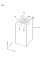
- FIG. 4 is a diagram showing the external shape and cutting position of a ceramic body used when examining the flatness of the external electrode paste.
- (a) is a diagram schematically showing a cross section of a multilayer ceramic capacitor in which external electrodes are formed using the paste for external electrodes of the present invention
- (b) is a diagram showing external electrodes formed using a conventional paste for external electrodes.
- 1 is a diagram schematically showing a cross section of a laminated ceramic capacitor in which .
- the external electrode paste in one embodiment contains a resin, a metal filler, and a solvent.
- the resin, metal filler, and solvent are described in detail below.
- the type of resin is not particularly limited as long as the desired effects are not inhibited.
- various resins conventionally blended in external electrode pastes can be used without particular limitation.
- Preferred resins include, for example, cellulose-based resins, acrylic-based resins, and butyral-based resins. It is particularly preferable that the resin contains a cellulose-based resin because it is easy to obtain an external electrode paste having a viscosity suitable for forming the external electrodes. It is also preferred that the resin comprises a copolymer resin having blocks derived from cellulosic resins. Such copolymer resin may be a block copolymer or a graft copolymer.
- the cellulosic resin is, for example, at least one of ethyl cellulose, methyl cellulose, hydroxypropyl cellulose, trityl cellulose, acetyl cellulose, carboxymethyl cellulose, and nitrocellulose.
- the acrylic resin is, for example, a homopolymer of one or more monomers consisting of isobutyl methacrylate, methyl methacrylate, hydroxyethyl methacrylate, hydroxypropyl methacrylate, n-butyl methacrylate, and 2-ethylhexyl methacrylate. or a copolymer.
- the metal filler is made of metal that constitutes the external electrodes.
- the type of metal that constitutes the metal filler is appropriately selected according to the type of metal that constitutes the external electrode.
- Preferred metals are copper (Cu), silver (Ag), nickel (Ni), and alloys containing these metals, because of their excellent conductivity and easy availability of metal fillers with desired particle sizes.
- the alloy containing these metals preferably contains one or more selected from the group consisting of copper (Cu), silver (Ag) and nickel (Ni). Also, the alloy containing these metals preferably contains tin (Sn).
- the metal filler preferably has a coat layer on its surface.
- a method for forming the coat layer is not particularly limited.
- the metal filler may be coated with a coating layer by drying the solution adhering to the metal filler while spraying the solution of the coating agent toward the air current containing the metal filler.
- a coating agent capable of adhering or bonding to the metal surface may be adhered or bonded to the surface of the metal filler to form a coating layer.
- Coating agents include silane coupling agents, titanium coupling agents, aluminum coupling agents, aliphatic carboxylic acids, aliphatic thiols, and amine coupling agents.
- These coating agents may be used individually by 1 type, or may be used in combination of 2 or more type.
- aliphatic carboxylic acids and silane coupling agents are preferred because they have good bonding properties to the surface of the metal filler, and are inexpensive and readily available.
- Silane coupling agents include, for example, methyltrimethoxysilane, dimethyldimethoxysilane, phenyltrimethoxysilane, methyltriethoxysilane, dimethyldiethoxysilane, phenyltriethoxysilane, n-propyltrimethoxysilane, n-propyltriethoxysilane.
- the particle diameter of the metal filler is preferably 80 nm or more and 1000 nm or less, more preferably 90 nm or more and 800 nm or less, and particularly preferably 100 nm or more and 500 nm or less.
- the particle size of the metal filler is the median system D50 obtained by observing the metal filler with a scanning electron microscope.
- the particle size of the metal filler includes the thickness of the coat layer.
- the external electrode paste contains a solvent as a component that dissolves the aforementioned resin, disperses the metal filler, and imparts fluidity to the paste.
- the solvent includes one or more first solvents and one or more second solvents.
- the ratio of the mass of the first solvent and the ratio of the mass of the second solvent to the mass of the solvent are each 40% by mass or more.
- the lowest boiling point T Hl among the boiling points under atmospheric pressure of the one or more second solvents is higher than the highest boiling point T Lh among the boiling points under atmospheric pressure of the one or more first solvents by 10°C or more.
- the highest boiling point T Hh among the boiling points under atmospheric pressure of the one or more second solvents is T Hl +10° C. or less.
- the lowest boiling point T Ll among the boiling points under atmospheric pressure of the one or more first solvents is T Lh ⁇ 10° C. or higher.
- the solvent may contain a sub-solvent in addition to the first solvent and the second solvent.
- the solvent consists of a first solvent and a second solvent, or consists of a first solvent, a second solvent and a secondary solvent.
- the boiling point of the secondary solvent under atmospheric pressure is less than (T Ll ⁇ 10)° C., more than (T Lh +10)° C. and less than (T Hl ⁇ 10)° C., or more than (T Hh +10)° C. for the external electrode. Paste.
- the solvent includes one or more first solvents and one or more second solvents.
- the number of first solvents is preferably one or two, preferably one.
- the number of second solvents is one or two.
- the ratio of the mass of the first solvent and the ratio of the mass of the second solvent to the mass of the solvent are each 40% by mass or more.
- it is easy to prevent the central portion from swelling compared to the end portions. is preferably 90% by mass or more, more preferably 95% by mass or more, and even more preferably 100% by mass.
- the lowest atmospheric pressure boiling point T Hl of the one or more second solvents is 10 times higher than the highest atmospheric pressure boiling point T Lh of the one or more first solvent °C or higher. Since the external electrode paste contains the second solvent and the first solvent that satisfy such a difference in boiling point, swelling of the center portion compared to the end portions is suppressed when the external electrode paste is applied. It's easy to do.
- T Hl is preferably 20° C. or more higher than T Lh , more preferably 30° C. or more.
- T Hl is preferably (T Lh +100) ° C. or less, more preferably (T Lh +80) ° C. or less, and (T Lh +50)°C or less is more preferable.
- the boiling point under atmospheric pressure of each of the one or more solvents constituting the second solvent is not particularly limited as long as the desired effect can be obtained.
- the boiling point under atmospheric pressure of the one or more solvents constituting the second solvent is preferably 200° C. or higher and 300° C. or lower, more preferably 210° C. or higher and 250° C. or lower.
- the boiling point under atmospheric pressure of each of the one or more solvents constituting the first solvent is not particularly limited as long as the desired effect can be obtained.
- the boiling point under atmospheric pressure of the one or more solvents constituting the first solvent is preferably 150° C. or higher and 240° C. or lower, more preferably 200° C. or higher and 230° C. or lower.
- the difference between the weighted average value of the surface tension of the second solvent and the weighted average value of the surface tension of the first solvent is preferably 3 mN/m or more, more preferably 8 mN/m or more. Either the surface tension of the first solvent or the surface tension of the second solvent may be higher.
- the weighted average value of the surface tension of the second solvent and the weighted average value of the surface tension of the first solvent satisfy the above relationship, when the external electrode paste is applied to form a film, the end portion It is easy to suppress swelling of the central portion compared to .
- the weighted average value of the surface tension of the second solvent is preferably 23 mN/m or more and 50 mN/m or less.
- the weighted average value of the surface tension of the first solvent is preferably 20 mN/m or more and 47 mN/m or less.
- the ratio of the solvent mass to the mass of the external electrode paste is preferably 35% by mass or more and 50% by mass or less, more preferably 37.5% by mass or more and 45% by mass or less.
- solvents include texanol, propylene glycol monophenyl ether, butyl carbitol, terpene solvents, diethylene glycol, carbitol acetate, butyl carbitol acetate, benzyl alcohol, methylpropylene diglycol, diphenyl ether, ethylene glycol, and the like. is mentioned.
- the external electrode paste may contain optional components such as a glass frit, a dispersant, and a thickener along with the resin and metal filler described above. These optional components are appropriately used in consideration of the amount normally used in the external electrode paste.
- the external electrode paste can be obtained by dissolving and dispersing the resins and metal fillers described above, and optionally the above-described optional components, in a desired ratio in a solvent that satisfies the above-described predetermined requirements. .
- FIG. 1 is a diagram for explaining the process of applying the external electrode paste 11 to the ceramic body 12 in this embodiment.
- the regions where the external electrodes of the ceramic body 12 are to be formed are immersed in the external electrode paste 11 (see FIG. 1(a)).
- the ceramic body 12 is pulled up (see FIG. 1(b)).
- the regions where the external electrodes are formed are, for example, both end faces of the ceramic body 12 .
- the external electrode paste applied to the ceramic body 12 is denoted by 11a.
- the coating amount of the external electrode paste is smaller at the end part, and the gas-liquid interface per volume at the end part is larger. For this reason, drying progresses more easily at the ends. Therefore, the ratio of the solid content (resin and metal filler) in the external electrode paste is higher in the end portion than in the center portion. As a result, the solid-liquid interface increases at the edge relative to the center, making the edge energetically unstable.
- the first solvent preferentially volatilizes. For these reasons, the solvent moves from the central portion to the end portions so that the concentration gradient of the solid content in the external electrode paste is relaxed. Also, convection of the solvent from the center to the ends is generated so that the composition of the solvent is homogenized.
- the solvent moves so that the composition of the solvent becomes uniform during the process of drying the external electrode paste 11a on the ceramic body 12. .
- This solvent movement serves to promote outward flow. Due to the strong outward flow, the external electrode paste 11a flows from the central portion to the end portions. Therefore, it is possible to prevent the external electrode paste 11a from swelling outward in the central portion (see FIG. 1(d)).
- the external electrode paste in the present embodiment contains predetermined amounts of the above-described second solvent and first solvent as solvents, and therefore has better fluidity than conventional external electrode pastes.
- the use of the external electrode paste according to the present embodiment can suppress swelling of the center portion compared to the end portions. Therefore, an electronic component manufactured using the external electrode paste in this embodiment is miniaturized.
- FIG. 2(a) is a diagram schematically showing a cross section of a multilayer ceramic capacitor 20a in which external electrodes 22a are formed on a ceramic body 21a using the external electrode paste of the present embodiment.
- FIG. 2(b) is a schematic cross-sectional view of a multilayer ceramic capacitor 20b in which external electrodes 22b are formed on a ceramic body 21b using a conventional external electrode paste.
- the shape of the external electrode 22b formed using the conventional external electrode paste is a convex shape with a thick central portion and thin end portions.
- the shape of the external electrode 22a formed using the external electrode paste in the present embodiment is a flat shape in which swelling at the central portion is suppressed. Therefore, by forming the external electrodes using the external electrode paste of the present embodiment, the size of the multilayer ceramic capacitor can be reduced. In addition, when compared with the same size, the external electrodes can be made thinner and the internal elements can be made larger, so that the capacity can be increased.
- the method of applying the external electrode paste to the ceramic body in this embodiment is not limited to the immersion in the external electrode paste described above.
- the external electrode paste described above can be used when forming external electrodes of electronic components, such as multilayer ceramic capacitors.
- An electronic component manufactured using this external electrode paste includes the steps of preparing an electronic component element, applying the external electrode paste of the present embodiment to the outer surface of the electronic component element, and applying the applied external and a step of forming the external electrodes by baking the electrode paste.
- a step of drying the external electrode paste may be included between the step of applying the external electrode paste and the step of baking the applied external electrode paste.
- An electronic component element has, for example, a structure in which a plurality of ceramic layers and internal electrodes are alternately laminated.
- solvents S1 to S5 having the following boiling points and surface tensions were used.
- the boiling point described below is a boiling point under atmospheric pressure.
- S1 Boiling point 244°C, surface tension 26mN/m
- S2 Boiling point 205°C, surface tension 48mN/m
- S3 Boiling point 244°C, surface tension 28mN/m
- S4 Boiling point 218°C, surface tension 31mN/m
- S5 Boiling point 220°C, surface tension 29mN/m
- Example 1 In Examples 1 to 8, Examples 10 to 18, Comparative Examples 1, and 2, copper fine particles having the average diameter shown in Table 2 and provided with a coat layer were used as metal fillers. In Example 9, the same particles having the average diameter shown in Table 2 and having no coating layer were used as the metal filler.
- a ceramic body 40 having a dimension in the length direction L of 1.0 mm, a dimension in the width direction W of 0.5 mm, and a dimension in the thickness direction T of 0.5 mm was prepared.
- This ceramic body 40 was formed by firing a laminated body in which a plurality of ceramic green sheets, which constitute a laminated ceramic capacitor after formation of external electrodes and were coated with paste for internal electrodes, were laminated.
- the internal electrodes 42 were exposed on the end face 41 of the ceramic body 40 and the end face located on the opposite side of the end face 41 in the length direction L. As shown in FIG.
- the external electrode paste applied to the end face 41 of the ceramic body 40 and its periphery was dried. Then, the difference in film thickness of the external electrode paste was examined when the ceramic body 40 was cut along the AA cutting line and the BB cutting line shown in FIG. More specifically, the thickness of the thickest part of the thickness of the external electrode paste at the position where the ceramic body 40 is cut along the AA cutting line, and the thickness of the ceramic body 40 at the BB cut The difference between the film thickness of the thinnest portion of the film thickness of the external electrode paste at the position cut along the line was examined.
- the film thickness at the thickest portion is the film thickness at the central position in the thickness direction T. is.
- the film thickness at the thinnest portion is the film thickness at the end in the thickness direction T. is.
- the AA cutting line is the cutting line along the plane defined by the length direction L and the thickness direction T at the center position of the width direction W of the ceramic body 40.
- the BB cutting line is a line parallel to the AA cutting line and is a cutting line at the position of the end of the internal electrode 42 in the width direction W of the ceramic body 40 .
- the position of the BB cutting line is, for example, a position 30 ⁇ m inside in the width direction W from the end of the ceramic body 40 in the width direction.
- ⁇ Density (void) evaluation> After the external electrode pastes of each example and comparative example were formed into films in the same manner as in the flatness evaluation, the obtained films were sintered at a maximum temperature of 750° C. in a nitrogen atmosphere. The sintered film was observed with a scanning electron microscope (SEM) from a direction substantially perpendicular to the end surface 41 of the ceramic body 40 . From the observed image obtained, the ratio of the area of the void portion to the area of the film after sintering was obtained. A case in which the area ratio of void portions was less than 1.6% was evaluated as ⁇ . A case where the ratio of the area of the void portion was 1.6% or more and less than 2.0% was evaluated as ⁇ . A case where the area ratio of the void portion was 2.0% or more was determined as x.
- the external electrode paste contains a combination of the first solvent and the second solvent so as to satisfy the above-described predetermined requirements, when it is applied, it is It can be seen that it is possible to suppress the central part from becoming swollen, and to suppress the generation of voids when the coated film is sintered.
- Comparative Examples 1 and 2 when the external electrode paste does not contain a combination of the first solvent and the second solvent so as to satisfy the above-described predetermined requirements, when coated, It can be seen that it is not possible to simultaneously suppress the formation of a shape in which the center portion swells more than the end portions and suppress the generation of voids when the coated film is sintered.
Landscapes
- Engineering & Computer Science (AREA)
- Chemical & Material Sciences (AREA)
- Power Engineering (AREA)
- Manufacturing & Machinery (AREA)
- Physics & Mathematics (AREA)
- Spectroscopy & Molecular Physics (AREA)
- Microelectronics & Electronic Packaging (AREA)
- Inorganic Chemistry (AREA)
- Ceramic Engineering (AREA)
- Dispersion Chemistry (AREA)
- Mechanical Engineering (AREA)
- Thermal Sciences (AREA)
- Health & Medical Sciences (AREA)
- Chemical Kinetics & Catalysis (AREA)
- Medicinal Chemistry (AREA)
- Polymers & Plastics (AREA)
- Organic Chemistry (AREA)
- Fixed Capacitors And Capacitor Manufacturing Machines (AREA)
- Ceramic Capacitors (AREA)
Priority Applications (2)
| Application Number | Priority Date | Filing Date | Title |
|---|---|---|---|
| JP2023518636A JP7663122B2 (ja) | 2021-05-06 | 2022-03-23 | 外部電極用ペースト |
| KR1020237037687A KR102840588B1 (ko) | 2021-05-06 | 2022-03-23 | 외부전극용 페이스트 |
Applications Claiming Priority (2)
| Application Number | Priority Date | Filing Date | Title |
|---|---|---|---|
| JP2021078673 | 2021-05-06 | ||
| JP2021-078673 | 2021-05-06 |
Publications (1)
| Publication Number | Publication Date |
|---|---|
| WO2022234739A1 true WO2022234739A1 (ja) | 2022-11-10 |
Family
ID=83932148
Family Applications (1)
| Application Number | Title | Priority Date | Filing Date |
|---|---|---|---|
| PCT/JP2022/013440 Ceased WO2022234739A1 (ja) | 2021-05-06 | 2022-03-23 | 外部電極用ペースト |
Country Status (3)
| Country | Link |
|---|---|
| JP (1) | JP7663122B2 (https=) |
| KR (1) | KR102840588B1 (https=) |
| WO (1) | WO2022234739A1 (https=) |
Cited By (2)
| Publication number | Priority date | Publication date | Assignee | Title |
|---|---|---|---|---|
| WO2025013381A1 (ja) * | 2023-07-10 | 2025-01-16 | 株式会社村田製作所 | 3端子型積層セラミックコンデンサ |
| WO2025013380A1 (ja) * | 2023-07-10 | 2025-01-16 | 株式会社村田製作所 | 3端子型積層セラミックコンデンサ |
Citations (3)
| Publication number | Priority date | Publication date | Assignee | Title |
|---|---|---|---|---|
| JP2000286142A (ja) * | 1999-03-31 | 2000-10-13 | Kyocera Corp | 積層セラミックコンデンサおよび外部電極ペースト |
| JP2002140934A (ja) * | 2000-08-24 | 2002-05-17 | Murata Mfg Co Ltd | 導電性ペーストならびにセラミック電子部品 |
| JP2015124252A (ja) * | 2013-12-25 | 2015-07-06 | 株式会社ノリタケカンパニーリミテド | 加熱硬化型導電性ペースト |
Family Cites Families (1)
| Publication number | Priority date | Publication date | Assignee | Title |
|---|---|---|---|---|
| JP5715535B2 (ja) | 2011-09-27 | 2015-05-07 | 互応化学工業株式会社 | 焼成用バインダー組成物 |
-
2022
- 2022-03-23 KR KR1020237037687A patent/KR102840588B1/ko active Active
- 2022-03-23 WO PCT/JP2022/013440 patent/WO2022234739A1/ja not_active Ceased
- 2022-03-23 JP JP2023518636A patent/JP7663122B2/ja active Active
Patent Citations (3)
| Publication number | Priority date | Publication date | Assignee | Title |
|---|---|---|---|---|
| JP2000286142A (ja) * | 1999-03-31 | 2000-10-13 | Kyocera Corp | 積層セラミックコンデンサおよび外部電極ペースト |
| JP2002140934A (ja) * | 2000-08-24 | 2002-05-17 | Murata Mfg Co Ltd | 導電性ペーストならびにセラミック電子部品 |
| JP2015124252A (ja) * | 2013-12-25 | 2015-07-06 | 株式会社ノリタケカンパニーリミテド | 加熱硬化型導電性ペースト |
Cited By (2)
| Publication number | Priority date | Publication date | Assignee | Title |
|---|---|---|---|---|
| WO2025013381A1 (ja) * | 2023-07-10 | 2025-01-16 | 株式会社村田製作所 | 3端子型積層セラミックコンデンサ |
| WO2025013380A1 (ja) * | 2023-07-10 | 2025-01-16 | 株式会社村田製作所 | 3端子型積層セラミックコンデンサ |
Also Published As
| Publication number | Publication date |
|---|---|
| KR102840588B1 (ko) | 2025-07-30 |
| JPWO2022234739A1 (https=) | 2022-11-10 |
| JP7663122B2 (ja) | 2025-04-16 |
| KR20230163557A (ko) | 2023-11-30 |
Similar Documents
| Publication | Publication Date | Title |
|---|---|---|
| JP7192743B2 (ja) | 外部電極用ペースト | |
| JP6787364B2 (ja) | 導電性ペースト | |
| JP5815594B2 (ja) | 積層セラミック電子部品 | |
| JP7663122B2 (ja) | 外部電極用ペースト | |
| US20180301280A1 (en) | Conductive paste for external electrode and method for manufacturing electronic component including the conductive paste for external electrode | |
| JP2011137128A (ja) | 導電性樹脂組成物およびチップ型電子部品 | |
| CN101189693A (zh) | 电子器件及其制作方法 | |
| JP7088134B2 (ja) | 電子部品 | |
| JP2023018152A (ja) | 積層セラミックコンデンサ | |
| WO2020137290A1 (ja) | 導電性ペースト、電子部品、及び積層セラミックコンデンサ | |
| JP2021019008A (ja) | 電子部品 | |
| JP2002056716A (ja) | 導電性ペーストおよび積層セラミック電子部品 | |
| US9251925B2 (en) | Conductive paste for external electrodes and multilayer ceramic electronic component using the same | |
| JP2022163228A (ja) | チップ型セラミック電子部品 | |
| WO2022168770A1 (ja) | 電解コンデンサ | |
| JP5630363B2 (ja) | 導電性ペーストおよびその製造方法 | |
| JP2021010034A (ja) | チップ型セラミック電子部品 | |
| TWI734769B (zh) | 導體形成用糊及積層陶瓷電容器 | |
| JP4766505B2 (ja) | セラミックスラリー、セラミックグリーンシートおよび積層セラミック電子部品 | |
| US10861650B2 (en) | Multilayer ceramic electronic component and method of manufacturing the same | |
| US20150116895A1 (en) | Conductive paste composition for external electrode, multilayer ceramic electronic component using the same, and manufacturing method thereof | |
| JP2001184942A (ja) | セラミックコンデンサー電極形成用ペースト | |
| JP2009146732A (ja) | セラミック電子部品用導電性ペーストおよびセラミック電子部品 | |
| JP2003297146A (ja) | 導電性ペースト、およびそれを用いた積層セラミック電子部品 | |
| JP7447804B2 (ja) | 積層インダクタの内部電極形成用銀ペースト |
Legal Events
| Date | Code | Title | Description |
|---|---|---|---|
| 121 | Ep: the epo has been informed by wipo that ep was designated in this application |
Ref document number: 22798846 Country of ref document: EP Kind code of ref document: A1 |
|
| WWE | Wipo information: entry into national phase |
Ref document number: 2023518636 Country of ref document: JP |
|
| ENP | Entry into the national phase |
Ref document number: 20237037687 Country of ref document: KR Kind code of ref document: A |
|
| WWE | Wipo information: entry into national phase |
Ref document number: 1020237037687 Country of ref document: KR |
|
| NENP | Non-entry into the national phase |
Ref country code: DE |
|
| 122 | Ep: pct application non-entry in european phase |
Ref document number: 22798846 Country of ref document: EP Kind code of ref document: A1 |