WO2022231013A1 - リング状物体の製造方法、成膜装置、リング状物体、及びハードディスクドライブ装置 - Google Patents
リング状物体の製造方法、成膜装置、リング状物体、及びハードディスクドライブ装置 Download PDFInfo
- Publication number
- WO2022231013A1 WO2022231013A1 PCT/JP2022/019495 JP2022019495W WO2022231013A1 WO 2022231013 A1 WO2022231013 A1 WO 2022231013A1 JP 2022019495 W JP2022019495 W JP 2022019495W WO 2022231013 A1 WO2022231013 A1 WO 2022231013A1
- Authority
- WO
- WIPO (PCT)
- Prior art keywords
- ring
- film
- plate
- shaped
- glass substrate
- Prior art date
- Legal status (The legal status is an assumption and is not a legal conclusion. Google has not performed a legal analysis and makes no representation as to the accuracy of the status listed.)
- Ceased
Links
Images



Classifications
-
- G—PHYSICS
- G11—INFORMATION STORAGE
- G11B—INFORMATION STORAGE BASED ON RELATIVE MOVEMENT BETWEEN RECORD CARRIER AND TRANSDUCER
- G11B33/00—Constructional parts, details or accessories not provided for in the other groups of this subclass
- G11B33/14—Reducing influence of physical parameters, e.g. temperature change, moisture, dust
- G11B33/1406—Reducing the influence of the temperature
- G11B33/1433—Reducing the influence of the temperature by reducing the effects of the thermal expansion
-
- B—PERFORMING OPERATIONS; TRANSPORTING
- B05—SPRAYING OR ATOMISING IN GENERAL; APPLYING FLUENT MATERIALS TO SURFACES, IN GENERAL
- B05B—SPRAYING APPARATUS; ATOMISING APPARATUS; NOZZLES
- B05B12/00—Arrangements for controlling delivery; Arrangements for controlling the spray area
- B05B12/16—Arrangements for controlling delivery; Arrangements for controlling the spray area for controlling the spray area
- B05B12/18—Arrangements for controlling delivery; Arrangements for controlling the spray area for controlling the spray area using fluids, e.g. gas streams
-
- B—PERFORMING OPERATIONS; TRANSPORTING
- B05—SPRAYING OR ATOMISING IN GENERAL; APPLYING FLUENT MATERIALS TO SURFACES, IN GENERAL
- B05B—SPRAYING APPARATUS; ATOMISING APPARATUS; NOZZLES
- B05B7/00—Spraying apparatus for discharge of liquids or other fluent materials from two or more sources, e.g. of liquid and air, of powder and gas
- B05B7/02—Spray pistols; Apparatus for discharge
- B05B7/04—Spray pistols; Apparatus for discharge with arrangements for mixing liquids or other fluent materials before discharge
-
- B—PERFORMING OPERATIONS; TRANSPORTING
- B05—SPRAYING OR ATOMISING IN GENERAL; APPLYING FLUENT MATERIALS TO SURFACES, IN GENERAL
- B05D—PROCESSES FOR APPLYING FLUENT MATERIALS TO SURFACES, IN GENERAL
- B05D1/00—Processes for applying liquids or other fluent materials
- B05D1/02—Processes for applying liquids or other fluent materials performed by spraying
-
- B—PERFORMING OPERATIONS; TRANSPORTING
- B05—SPRAYING OR ATOMISING IN GENERAL; APPLYING FLUENT MATERIALS TO SURFACES, IN GENERAL
- B05D—PROCESSES FOR APPLYING FLUENT MATERIALS TO SURFACES, IN GENERAL
- B05D3/00—Pretreatment of surfaces to which liquids or other fluent materials are to be applied; After-treatment of applied coatings, e.g. intermediate treating of an applied coating preparatory to subsequent applications of liquids or other fluent materials
-
- B—PERFORMING OPERATIONS; TRANSPORTING
- B05—SPRAYING OR ATOMISING IN GENERAL; APPLYING FLUENT MATERIALS TO SURFACES, IN GENERAL
- B05D—PROCESSES FOR APPLYING FLUENT MATERIALS TO SURFACES, IN GENERAL
- B05D7/00—Processes, other than flocking, specially adapted for applying liquids or other fluent materials to particular surfaces or for applying particular liquids or other fluent materials
-
- C—CHEMISTRY; METALLURGY
- C03—GLASS; MINERAL OR SLAG WOOL
- C03C—CHEMICAL COMPOSITION OF GLASSES, GLAZES OR VITREOUS ENAMELS; SURFACE TREATMENT OF GLASS; SURFACE TREATMENT OF FIBRES OR FILAMENTS MADE FROM GLASS, MINERALS OR SLAGS; JOINING GLASS TO GLASS OR OTHER MATERIALS
- C03C17/00—Surface treatment of glass, not in the form of fibres or filaments, by coating
- C03C17/22—Surface treatment of glass, not in the form of fibres or filaments, by coating with other inorganic material
- C03C17/23—Oxides
- C03C17/245—Oxides by deposition from the vapour phase
-
- C—CHEMISTRY; METALLURGY
- C03—GLASS; MINERAL OR SLAG WOOL
- C03C—CHEMICAL COMPOSITION OF GLASSES, GLAZES OR VITREOUS ENAMELS; SURFACE TREATMENT OF GLASS; SURFACE TREATMENT OF FIBRES OR FILAMENTS MADE FROM GLASS, MINERALS OR SLAGS; JOINING GLASS TO GLASS OR OTHER MATERIALS
- C03C17/00—Surface treatment of glass, not in the form of fibres or filaments, by coating
- C03C17/22—Surface treatment of glass, not in the form of fibres or filaments, by coating with other inorganic material
- C03C17/23—Oxides
- C03C17/245—Oxides by deposition from the vapour phase
- C03C17/2453—Coating containing SnO2
-
- C—CHEMISTRY; METALLURGY
- C03—GLASS; MINERAL OR SLAG WOOL
- C03C—CHEMICAL COMPOSITION OF GLASSES, GLAZES OR VITREOUS ENAMELS; SURFACE TREATMENT OF GLASS; SURFACE TREATMENT OF FIBRES OR FILAMENTS MADE FROM GLASS, MINERALS OR SLAGS; JOINING GLASS TO GLASS OR OTHER MATERIALS
- C03C17/00—Surface treatment of glass, not in the form of fibres or filaments, by coating
- C03C17/22—Surface treatment of glass, not in the form of fibres or filaments, by coating with other inorganic material
- C03C17/23—Oxides
- C03C17/245—Oxides by deposition from the vapour phase
- C03C17/2456—Coating containing TiO2
-
- G—PHYSICS
- G11—INFORMATION STORAGE
- G11B—INFORMATION STORAGE BASED ON RELATIVE MOVEMENT BETWEEN RECORD CARRIER AND TRANSDUCER
- G11B17/00—Guiding record carriers not specifically of filamentary or web form, or of supports therefor
- G11B17/02—Details
- G11B17/038—Centering or locking of a plurality of discs in a single cartridge
-
- G—PHYSICS
- G11—INFORMATION STORAGE
- G11B—INFORMATION STORAGE BASED ON RELATIVE MOVEMENT BETWEEN RECORD CARRIER AND TRANSDUCER
- G11B23/00—Record carriers not specific to the method of recording or reproducing; Accessories, e.g. containers, specially adapted for co-operation with the recording or reproducing apparatus ; Intermediate mediums; Apparatus or processes specially adapted for their manufacture
-
- C—CHEMISTRY; METALLURGY
- C03—GLASS; MINERAL OR SLAG WOOL
- C03C—CHEMICAL COMPOSITION OF GLASSES, GLAZES OR VITREOUS ENAMELS; SURFACE TREATMENT OF GLASS; SURFACE TREATMENT OF FIBRES OR FILAMENTS MADE FROM GLASS, MINERALS OR SLAGS; JOINING GLASS TO GLASS OR OTHER MATERIALS
- C03C2217/00—Coatings on glass
- C03C2217/20—Materials for coating a single layer on glass
- C03C2217/21—Oxides
- C03C2217/211—SnO2
-
- C—CHEMISTRY; METALLURGY
- C03—GLASS; MINERAL OR SLAG WOOL
- C03C—CHEMICAL COMPOSITION OF GLASSES, GLAZES OR VITREOUS ENAMELS; SURFACE TREATMENT OF GLASS; SURFACE TREATMENT OF FIBRES OR FILAMENTS MADE FROM GLASS, MINERALS OR SLAGS; JOINING GLASS TO GLASS OR OTHER MATERIALS
- C03C2217/00—Coatings on glass
- C03C2217/20—Materials for coating a single layer on glass
- C03C2217/21—Oxides
- C03C2217/216—ZnO
-
- C—CHEMISTRY; METALLURGY
- C03—GLASS; MINERAL OR SLAG WOOL
- C03C—CHEMICAL COMPOSITION OF GLASSES, GLAZES OR VITREOUS ENAMELS; SURFACE TREATMENT OF GLASS; SURFACE TREATMENT OF FIBRES OR FILAMENTS MADE FROM GLASS, MINERALS OR SLAGS; JOINING GLASS TO GLASS OR OTHER MATERIALS
- C03C2217/00—Coatings on glass
- C03C2217/20—Materials for coating a single layer on glass
- C03C2217/21—Oxides
- C03C2217/24—Doped oxides
-
- C—CHEMISTRY; METALLURGY
- C03—GLASS; MINERAL OR SLAG WOOL
- C03C—CHEMICAL COMPOSITION OF GLASSES, GLAZES OR VITREOUS ENAMELS; SURFACE TREATMENT OF GLASS; SURFACE TREATMENT OF FIBRES OR FILAMENTS MADE FROM GLASS, MINERALS OR SLAGS; JOINING GLASS TO GLASS OR OTHER MATERIALS
- C03C2217/00—Coatings on glass
- C03C2217/20—Materials for coating a single layer on glass
- C03C2217/21—Oxides
- C03C2217/24—Doped oxides
- C03C2217/241—Doped oxides with halides
-
- C—CHEMISTRY; METALLURGY
- C03—GLASS; MINERAL OR SLAG WOOL
- C03C—CHEMICAL COMPOSITION OF GLASSES, GLAZES OR VITREOUS ENAMELS; SURFACE TREATMENT OF GLASS; SURFACE TREATMENT OF FIBRES OR FILAMENTS MADE FROM GLASS, MINERALS OR SLAGS; JOINING GLASS TO GLASS OR OTHER MATERIALS
- C03C2218/00—Methods for coating glass
- C03C2218/10—Deposition methods
- C03C2218/11—Deposition methods from solutions or suspensions
- C03C2218/112—Deposition methods from solutions or suspensions by spraying
-
- C—CHEMISTRY; METALLURGY
- C03—GLASS; MINERAL OR SLAG WOOL
- C03C—CHEMICAL COMPOSITION OF GLASSES, GLAZES OR VITREOUS ENAMELS; SURFACE TREATMENT OF GLASS; SURFACE TREATMENT OF FIBRES OR FILAMENTS MADE FROM GLASS, MINERALS OR SLAGS; JOINING GLASS TO GLASS OR OTHER MATERIALS
- C03C2218/00—Methods for coating glass
- C03C2218/10—Deposition methods
- C03C2218/15—Deposition methods from the vapour phase
- C03C2218/152—Deposition methods from the vapour phase by cvd
-
- C—CHEMISTRY; METALLURGY
- C03—GLASS; MINERAL OR SLAG WOOL
- C03C—CHEMICAL COMPOSITION OF GLASSES, GLAZES OR VITREOUS ENAMELS; SURFACE TREATMENT OF GLASS; SURFACE TREATMENT OF FIBRES OR FILAMENTS MADE FROM GLASS, MINERALS OR SLAGS; JOINING GLASS TO GLASS OR OTHER MATERIALS
- C03C2218/00—Methods for coating glass
- C03C2218/30—Aspects of methods for coating glass not covered above
- C03C2218/365—Coating different sides of a glass substrate
Definitions
- the present invention relates to a method for manufacturing a ring-shaped object by spray film formation on the entire surface of the ring-shaped object, a film forming apparatus, a ring-shaped object, and a hard disk drive.
- HDD devices hard disk drives
- HDD devices are provided with ring-shaped spacers between the magnetic disks to hold the magnetic disks apart.
- the spacer functions so that the magnetic disks do not come into contact with each other and are spaced apart at predetermined positions with high accuracy.
- a spacer material conventionally, a metal material having electrical conductivity and low manufacturing cost has been used.
- the spacer and the magnetic disk are in contact with each other. A difference in thermal expansion occurs between the spacer and the magnetic disk as the temperature changes. As a result, the magnetic disk is flexed, and the flying performance of the magnetic head may deteriorate. Deterioration of the flying property of the magnetic head is not preferable from the viewpoint of reading and writing of the magnetic disk in the HDD device. This problem becomes more serious as the recording density increases.
- glass spacers (hereinafter referred to as glass spacers) have been developed in order to correspond to the case where a glass substrate is used as a substrate for a magnetic disk (to bring the coefficient of linear expansion closer), or to make the spacer lighter and more rigid than before. is being considered.
- glass is an insulator
- static electricity tends to accumulate on the magnetic disk or spacer due to friction between the magnetic disk and glass spacer rotating at high speed and the air.
- the magnetic disk or spacer is charged, it is not preferable because foreign matter and fine particles are likely to be attracted to the magnetic disk and the magnetic head, and the accumulated static electricity may be discharged to the magnetic head, thereby destroying the recording element and the reproducing element of the magnetic head.
- a glass spacer in which at least the contact surface with the magnetic disk and the inner peripheral surface of the glass spacer are coated with a conductive ceramic film having a thickness of 0.1 to 3 ⁇ m (Patent Document 1). It is said that this allows the static electricity charged on the magnetic disk to be released efficiently, and hardly wears the contact surface.
- a PVD (Physical Vapor Deposition) method, a CVD (Chemical Vapor Deposition) method, or the like is used for film formation when manufacturing the glass spacer.
- these film forming methods there is generally a problem that the film cannot be formed on the portion where the spacer-holding member (supporting member) contacts the spacer. For this reason, a part of the surface of the spacer is exposed without forming a film due to the holding by the holding member, and glass fragments from the exposed part may become fine particles and generate dust. Further, in order to completely eliminate the exposed portion, it is possible to remove the once-film-formed spacer from the film-forming apparatus, hold the film-formed region with a holding member, and perform the second film formation. However, since the film is formed twice, there is a problem that the film thickness is uneven between the part in contact with the holding member and the other part. Furthermore, there is a problem that the film formation process becomes complicated and the manufacturing cost increases.
- the present invention has been made to solve the above-described problems, and in a method for manufacturing a ring-shaped object, the productivity of the film formation process is improved while suppressing film thickness unevenness on the surface of the ring-shaped object.
- the purpose is to provide a technology that enables
- a method for manufacturing a ring-shaped object comprising: placing the ring-shaped substrate on the plate; A gas containing a coating raw material is sprayed from above the ring-shaped substrate placed on the plate into a hole in the center of the ring-shaped substrate to float the ring-shaped substrate from the plate to form the ring-shaped substrate. and forming a film on a surface of a substrate.
- the plate may be a heated plate.
- the ring-shaped base material is lifted from the plate and landed on the plate a plurality of times. You can repeat.
- the injection pressure of the gas containing the coating raw material may be 0.05-1.0 MPa.
- the material of the ring-shaped substrate may include any one of glass, ceramics, metal, and resin.
- the film may be a conductive film or a film containing a conductive metal oxide.
- the ring-shaped object may be a hard disk drive spacer.
- a method for manufacturing a ring-shaped object comprising: A heat treatment in which the ring-shaped base material is placed on a mounting table and heated; and a film forming process for forming a film on the surface of the ring-shaped substrate by spraying a gas containing a coating material onto the ring-shaped substrate so as to float the ring-shaped substrate from the mounting table.
- a method of manufacturing an object is provided.
- a film forming apparatus comprising: a plate on which the ring-shaped substrate is placed; a positioning member provided on the plate for positioning the ring-shaped substrate within a predetermined range on the plate; and a nozzle provided above the plate for spraying a gas containing the coating raw material into the central hole of the ring-shaped substrate positioned by the member.
- the positioning member may be at least one screen erected outside the predetermined range on the plate.
- the film forming apparatus there may be a plurality of said screens, and two adjacent screens among them may be spaced apart so as to surround said predetermined range.
- the plate may be further provided with a convex portion, and the convex portion, when the ring-shaped substrate is positioned within the predetermined range, It may protrude from a hole in the center of the ring-shaped substrate.
- the positioning member may be a convex portion provided on the plate, and the ring-shaped substrate may extend from the center hole of the ring-shaped substrate to the Positioning within the predetermined range may be achieved by arranging the plate so that the convex portion protrudes.
- the film forming apparatus may further include a heater for heating the plate.
- a ring-shaped object a ring-shaped substrate having a first main surface and a second main surface facing each other, an outer peripheral end face, and an inner peripheral end face; A film formed on the entire surface of the ring-shaped base material, A ring-shaped object is provided in which the film thickness on the outer peripheral end face is thicker than the film thickness on the inner peripheral end face.
- the film thickness on the first main surface and the second main surface may be thicker than the film thickness on the outer peripheral end face.
- the material of the ring-shaped substrate may include any one of glass, ceramics, metal, and resin.
- the film may be a conductive film or a film containing a conductive metal oxide.
- the ring-shaped object according to the fourth aspect of the present invention may be a hard disk drive spacer.
- a hard disk drive including a ring-shaped object according to the fourth aspect of the present invention, a magnetic disk, and a magnetic head.
- the present invention in the method for manufacturing a ring-shaped object, it is possible to improve the productivity of the film formation process while suppressing film thickness unevenness on the surface of the ring-shaped object.
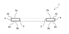
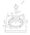
- FIG. 1(a) is a cross-sectional view of a main part explaining an example of the structure of an HDD device in which a glass spacer, which is an example of the ring-shaped object of the present invention, is incorporated, and FIG. FIG. 3 is a perspective view of a spacer; 1 is a cross-sectional view of a glass spacer that is an example of a ring-shaped object of the present invention; FIG. It is a figure explaining an example of the film-forming apparatus used with the manufacturing method of the ring-shaped object of this invention.
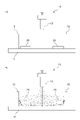
- FIG. 4 is a cross-sectional view taken along line IV-IV in FIG.
- the HDD device 100 mainly includes a plurality of glass spacers 1, a plurality of magnetic disks 105, a plurality of magnetic heads 106, a spindle 107, and a spindle motor 108.
- the glass spacer 1 is arranged between adjacent magnetic disks 105 in order to hold the plurality of magnetic disks 105 apart from each other at predetermined positions with high accuracy.
- the magnetic disks 105 and the glass spacers 1 are alternately stacked and inserted into the spindle 107 .
- the glass spacer 1 may be provided in contact with the upper surface of the magnetic disk 105 in the uppermost layer, or the glass spacer 1 may be provided in contact with the lower surface of the magnetic disk 105 in the lowermost layer.
- the glass spacer 1 is ring-shaped and has two main surfaces 2a and 2b facing each other, an inner peripheral end face 3 and an outer peripheral end face 4.
- the main surface 2a is an annular surface having two concentric circles as outer and inner edges.
- the main surface 2b has the same shape and is concentric with the main surface 2a.
- the inner peripheral end surface 3 is a surface connecting the inner edge of the main surface 2a and the inner edge of the main surface 2b
- the outer peripheral end surface 4 is a surface connecting the outer edge of the main surface 2a and the outer edge of the main surface 2b.
- a chamfered surface may be formed at each of the connecting portions between the two main surfaces 2a and 2b and the inner peripheral end surface 3 and the connecting portion between the two main surfaces 2a and 2b and the outer peripheral end surface 4.
- the cross-sectional shape of the chamfered surface may be linear or arcuate.
- the two main surfaces 2a and 2b are surfaces that come into contact with the magnetic disk.
- the inner peripheral end surface 3 is a surface that contacts the spindle 107 of the HDD device 100 and is a wall surface that surrounds a hole with an inner diameter slightly larger than the outer diameter of the spindle 107 .
- the outer peripheral end surface 4 is a surface that does not contact the magnetic disk 105 or the spindle 107 .
- the dimensions of the glass spacer 1 may be appropriately changed according to the specifications of the HDD device 100 to be mounted.
- the inner diameter (diameter) is, for example, 24-26 mm
- the radial width is, for example, 2-5 mm
- the thickness is, for example, 0.5-3 mm.
- the width of the chamfered surface in the radial direction and the plate thickness direction is, for example, 0.01 to 0.5 mm.
- the glass spacer 1 has a ring-shaped glass substrate 20 and a film 22 covering the entire surface of the glass substrate 20 . That is, the presence of the film 22 prevents the surface of the glass substrate 20 from being exposed. Therefore, static electricity is less likely to accumulate on the glass spacer 1 . In addition, it is possible to prevent a part of the glass substrate 20 from turning into fine particles, generating dust, and adhering to the magnetic disk. It is preferable that the cross-sectional shape of the glass substrate 20 is a rectangle whose length in the radial direction is longer than the length in the thickness direction, because the glass substrate 20 can be easily floated during the formation of the film 22, which will be described later.
- the coefficient of thermal expansion of the glass substrate 20 is preferably approximately equal to that of the glass substrate of the magnetic disk.
- the material of the glass substrate 20 is not particularly limited, and examples thereof include aluminosilicate glass, soda lime glass, soda aluminosilicate glass, aluminoboron silicate glass, boron silicate glass, and quartz glass. In terms of crystallinity, either amorphous glass or crystallized glass may be used. Amorphous glass is preferable because it has a relatively high hardness and is easy to increase the surface smoothness.
- the glass substrate 20 is made of amorphous aluminosilicate glass, for example, silicon dioxide (SiO 2 ): 59 to 63% by mass, aluminum oxide (Al 2 O 3 ): 5 to 16% by mass, lithium oxide (Li 2 O ): 2 to 10% by mass, sodium oxide (Na 2 O): 2 to 12% by mass, and zirconium oxide (ZrO 2 ): 0 to 5% by mass.
- This glass is suitable for the glass substrate 20 because of its high rigidity and low coefficient of thermal expansion.
- the glass substrate 20 is made of soda-lime glass, for example, SiO 2 : 65 to 75% by mass, Al 2 O 3 : 1 to 6% by mass, CaO: 2 to 7% by mass, Na 2 O: 5 to 17% by mass. %, and ZrO 2 : 0 to 5% by mass.
- Amorphous aluminosilicate glass and soda-lime glass are suitable for the glass substrate 20 because they are relatively easy to grind and polish, and are easy to increase the surface smoothness.
- the material of the glass substrate 20 may be cut into a ring shape from a sheet glass manufactured by the float method, the down-draw method, or the like, may be molded from molten glass by the press method, or may be manufactured by the tube drawing method. It may be sliced from a glass tube.
- the glass substrate 20 is obtained by grinding and/or polishing the end face (the inner peripheral end face and the outer peripheral end face) and the main surface of the ring-shaped glass thus formed.
- the method of grinding the end face is not particularly limited, and for example, grinding can be performed with a formed grindstone containing diamond abrasive grains of #80 to #1000. At this time, the chamfered surface can be formed at the same time.
- the end face may be polished using a polishing brush having bristles such as nylon. These end surface processing can be performed by rotating both the ring-shaped glass and the formed grindstone or the polishing brush to bring them into contact with each other, similarly to the end surface processing of the magnetic disk glass substrate.
- chemical polishing may be performed using an etchant containing hydrofluoric acid or silicic hydrofluoric acid.
- the film 22 is a conductive film, and may be a film containing a conductive metal oxide or a film containing a conductive ceramic.
- the film 22 can be a film containing any of tin oxide (SnO 2 ), zinc oxide (ZnO), and titanium oxide (TiO 2 ).
- the film 22 may be FTO, which is tin oxide doped with fluorine, or AZO, which is zinc oxide doped with aluminum oxide (Al 2 O 3 ).
- the degree of conductivity of the film 22 may be appropriately determined as necessary, but for example, the surface resistivity at 22[° C.] is 10 8 [ ⁇ /sq] or less.
- the thickness of the film 22 is preferably 200 nm or less, more preferably less than 100 nm. If the thickness exceeds 200 nm, the manufacturing cost may become excessive. Moreover, when the thickness is 100 nm or more, the surface unevenness of the film 22 may become large. If the projecting portion of the film 22 is too large, when it comes into contact with the magnetic disk, part of the projecting portion may separate from the film 22 and generate fine particles, causing the magnetic head to crash. On the other hand, the thickness of the film 22 is preferably 5 nm or more, more preferably 10 nm or more, in order to prevent dust generation and ion elution from the substrate surface.
- the film thickness of the outer peripheral end surface 4 is thicker than the film thickness of the inner peripheral end surface 3 . Since the film thickness of the outer peripheral end face 4 is thicker than the film thickness of the inner peripheral end face 3, it becomes easier to prevent the above troubles.
- the film thickness of each surface can be, for example, the film thickness at the central portion of each surface.
- the film forming apparatus 10 includes a plate 11 (also referred to as a mounting table) on which a ring-shaped glass substrate 20, which is an example of a ring-shaped base material, is mounted, a positioning member 12 provided on the plate 11, and a raw material for the film 22. and a housing (chamber) that accommodates them. Note that illustration of the housing is omitted in FIG.
- the plate 11 is, for example, a metal plate provided with heating means such as an electric heater, and can heat the glass substrate 20 mounted so as to be in contact with the upper surface (also referred to as mounting surface) of the plate 11 .
- the state in which the ring-shaped substrate such as the glass substrate 20 is mounted on the upper surface (mounting surface) of the plate 11 (mounting table) means that the ring-shaped substrate is in a floating state described later. It also includes a state of falling and riding on the upper surface of the plate 11 .
- the heating temperature of the glass substrate 20 may be appropriately adjusted according to the film to be formed, and is, for example, 300 to 600° C. when forming the conductive film 22 of tin oxide.
- the material of the plate 11 may be any material as long as it can withstand the heating temperature corresponding to the film to be formed. At least the area of the surface of the plate 11 that can come into contact with the glass substrate 20 is preferably flat so that it can be efficiently heated when it comes into contact with the glass substrate. Further, the surface roughness of the plate 11 is preferably 5 ⁇ m or less, more preferably 3 ⁇ m or less in terms of arithmetic mean roughness Ra. If the Ra exceeds 5 ⁇ m, the contact area with the glass substrate is reduced, making it difficult to heat quickly, and the surface of the glass substrate may be damaged when the glass substrate falls from the floating state. The above Ra can be measured, for example, with a stylus-type surface roughness tester.
- the plate 11 has, for example, a rectangular shape, and the length of each side is greater than the outer diameter of the glass substrate 20 . That is, the plate 11 has a size in which the entire glass substrate 20 can be accommodated.
- the positioning member 12 While the positioning member 12 is blowing the gas containing the raw material of the film 22 from the nozzle 13, the glass substrate 20 mounted on the upper surface of the plate 11 is projected from the predetermined range of the upper surface of the plate 11 by the air flow. provided to prevent It also has the role of maintaining a high concentration of the gas containing the raw material of the film 22 around the glass substrate 20 to reduce variations in film thickness over the entire surface of the glass substrate 20 and to increase the formation speed of the film 22. .
- the positioning member 12 is composed of one or a plurality of screens erected outside a predetermined range on the upper surface of the plate 11 so as to surround the predetermined range.
- the material of the screen is, for example, metal, glass, ceramics, or a combination of two or more of these materials.
- the predetermined range of the upper surface of the plate 11 means, for example, a circular range having a diameter approximately 3 to 50% larger than the outer diameter of the glass substrate 20 . It is more preferable that the predetermined range be a circular range having a diameter larger than the outer diameter of the glass substrate 20 by about 5 to 30%. Therefore, when the glass substrate 20 is placed within a predetermined range on the upper surface of the plate 11, there is space between the outer peripheral end surface of the glass substrate 20 and the inner surface of the positioning member 12 in the outer peripheral direction of the glass substrate 20. A space is at least partially defined therealong.
- the positioning member 12 is arranged at a predetermined distance from the outer peripheral end face of the glass substrate 20 (that is, with a predetermined gap).
- This gap is defined not only when the glass substrate 20 is placed on the upper surface of the plate 11 (the height from the plate 11 is assumed to be zero), but also when the glass substrate 20 is floated. It needs to be secured even when the height changes, but it does not necessarily have to be constant in the height direction. A film can be formed also on the outer peripheral end surface of the glass substrate 20 due to the presence of this gap.
- the positioning member 12 is composed of a plurality of screens, two adjacent screens are spaced apart. That is, a gap is formed between two adjacent screens.
- the size of the gap is not particularly limited as long as the glass substrate 20 floats stably. 1 to 15% of the circumferential length of the virtual circle whose radius is the distance to When the positioning member 12 is composed of a plurality of screens, it is preferable to use three or more screens. By doing so, the gaps can be arranged around the glass substrate 12 in a well-balanced manner, so that the floating stability can be improved.
- the shape of the positioning member 12 (more specifically, the shape of the wall surface of the positioning member 12 on the glass substrate 20 side) is a circle, arc, curve, straight line, polygonal line, Alternatively, it can have various shapes such as a shape in which these are combined.
- the height of the positioning member 12 may be appropriately determined according to the thickness of the glass substrate 20 and the height to be floated during film formation, and is, for example, 5 to 50 mm.
- a member may be further provided to prevent the glass substrate 20 from jumping over the positioning member 12 due to the airflow.
- a canopy projecting in the arrangement direction of the glass substrate 20 may be provided on the positioning member 12 .
- the shape of the eaves is preferably a shape that does not hinder the progress of the gas jetted from the nozzle 13 .
- the nozzle 13 is arranged above the plate 11 in the housing, and in a state where the glass substrate 20 is placed within a predetermined range on the upper surface of the plate 11, the central axis of the nozzle 13 (the central axis of ejection) are positioned so as to fit in the center hole of the glass substrate 20 .
- the central axis of the nozzle 13 is preferably vertical. Moreover, it is preferable that the central axis of the nozzle 13 passes through the center of the predetermined range. Then, from the nozzle 13 , the raw material of the film 22 is jetted together with gas such as air toward the center hole of the glass substrate 20 placed within a predetermined range on the upper surface of the plate 11 .
- the raw material of the film 22 becomes fine droplets (mist) and moves or floats within the housing.
- the injection pressure of the nozzle 13 can be set to 0.05 to 1.0 MPa, for example.
- a liquid obtained by dissolving a tin organic compound such as dibutyltin diacetate or dimethyltin dichloride in a solvent such as ethanol can be used as the raw material of the film 22 .
- the glass substrate 20 is placed on the top surface of the plate 11 within a predetermined range. That is, the glass substrate 20 is arranged inside the positioning member 12 . Then, by heating the plate 11 with an electric heater, the glass substrate 20 placed on the upper surface of the plate 11 is heated up to 400° C., for example.
- a gas containing raw materials for the film 22 is jetted from the nozzle 13 toward the hole in the center of the glass substrate 20. Then, as shown in FIG. The gas jetted from the nozzle 13 passes through the hole in the center of the glass substrate 20 and collides with the upper surface of the plate 11. Then, the gas flows along the upper surface of the plate 11 toward the radially outer side of the glass substrate 20, and the glass substrate It flows into a small gap between the bottom surface of 20 and the top surface of plate 11 . Thereby, the glass substrate 20 floats from the upper surface of the plate 11 .
- Part of the gas that has passed between the lower surface of the glass substrate 20 and the upper surface of the plate 11 passes through the gaps of the screens forming the positioning member 12 and flows to the outside of the positioning member 12, and the rest of the gas passes through the glass substrate. It flows upward along the inner surface of the positioning member 12 in the space between the outer peripheral end surface of the nozzle 20 and the inner surface of the positioning member 12 . That is, the gas injected from the nozzle 13 flows as indicated by the solid line arrow in FIG. 4(b). As a result, the glass substrate 20 floats from the plate 11, and the raw material mist of the film 22 floating in the housing adheres not only to the upper surface, the inner peripheral end surface, and the outer peripheral end surface of the glass substrate 20, but also to the lower surface.
- the mist of the raw material of the film 22 adheres to the entire surface of the glass substrate 20 .
- the solvent evaporates and the organic compound dissolved in the solvent undergoes a chemical reaction.
- a solid film 22 is formed on the entire surface of the glass substrate 20 .
- the temperature of the glass substrate 20 decreases due to floating away from the plate 11 and evaporation of the solvent adhering to the glass substrate 20 . Therefore, after the gas containing the material of the film 22 is injected from the nozzle 13 to float the glass substrate 20 from the plate 11 for a certain period of time, the injection from the nozzle 13 is stopped for a certain period of time. Thereby, the floating glass substrate 20 is landed on the upper surface of the plate 11, and the glass substrate 20 on which a part of the film 22 is formed is reheated.
- the temperature of the glass substrate 20 is maintained at a predetermined temperature and the glass substrate is heated.
- a film 22 having desired physical properties and thickness can be formed on the entire surface of the glass substrate 20 such that the surface of the glass substrate 20 is not exposed at all.
- a helical protrusion may be provided on the inner wall of the nozzle 13, and the nozzle 13 may be configured so that the gas containing the raw material of the film 22 is jetted in a spiral. is preferred.
- the upper surface, lower surface, A film can be formed on the inner peripheral end face and the outer peripheral end face at the same time.
- the film thickness can be easily controlled by intermittently jetting from the nozzle.
- the glass substrate 20 can be brought into contact with the gas containing the raw material of the film while the glass substrate 20 is floated without supporting the glass substrate 20 with a jig or the like, the film can be formed evenly. In addition, it becomes difficult for impurities to enter the film.
- the ring-shaped substrate repeats floating from the plate and landing on the plate multiple times. Then, the ring-shaped base material whose temperature has been lowered by rising from the heated plate is reheated by landing on the plate again. That is, the temperature and heating time of the ring-shaped substrate during film formation can be easily controlled. For example, in the case of forming a conductive tin oxide film, if the substrate temperature is too low, the chemical reaction of the organic compound, which is the raw material of the film, may be insufficient, resulting in insufficient film formation. Keeping it high is very important. That is, the method of the present invention is very suitable for a spray film forming method that requires high-temperature substrate heating.
- the predetermined range on the plate 11 is a circular range having a diameter approximately 3 to 50% larger than the outer diameter of the glass substrate 20, and the glass substrate 20 is placed within the predetermined range on the upper surface of the plate 11.
- a space is formed at least partially along the outer peripheral direction of the glass substrate 20 between the outer peripheral end surface of the glass substrate 20 and the inner surface of the positioning member 12 . Therefore, when the glass substrate 20 is floated from the plate 11 by the injection from the nozzle 13 , the glass substrate 20 finely vibrates or swings inside the positioning member 12 . By this vibration or rocking, it is possible to obtain the effect of reducing variations in film thickness on each surface of the glass substrate 20 .
- Example 1 A ring-shaped glass substrate 20 was placed on the upper surface of the plate 11 of the film forming apparatus 10, and the glass substrate 20 was heated.
- the specifications of the glass substrate 20 are an outer diameter of 32 mm, an inner diameter of 25 mm, and a thickness of 2 mm.
- the film forming apparatus 10 has a heatable mounting surface (plate) made of stainless steel and four arc-shaped screens (30 mm in height) of the same shape. They were arranged so that a space (corresponding to the above-mentioned "predetermined range") was formed, and a gap of 10 mm was provided between each other along the circumferential length of 90 degrees (see FIG. 3).
- the film thicknesses of the main surface 2a, the main surface 2b, the inner peripheral end surface 3, and the outer peripheral end surface 4 were 63 nm, 63 nm, 57 nm and 61 nm.
- the glass spacer 1 was obtained with an extremely small film thickness variation (maximum film thickness - minimum film thickness) of 6 nm for the four main surfaces of the glass spacer 1 .
- the film thickness of the inner peripheral end face 3 and the outer peripheral end face 4 was thinner than the film thickness of the main surfaces 2 a and 2 b, and the film thickness of the outer peripheral end face 4 was thicker than the film thickness of the inner peripheral end face 3 .
- there was no trace of holding by the holding member on the entire surface of the glass spacer 1 when the surface resistivity of the film 22 was measured, it was 10 8 [ ⁇ /sq] or less at 22 [°C]. If the film thickness variation rate of the four main surfaces of the glass spacer 1 is defined as (maximum film thickness - minimum film thickness)/(average film thickness) x 100 (%), then in the case of the glass spacer 1 It was about 9.8%.
- the film thickness variation rate is 30% or less, the film thickness distribution is small compared to the conventional film forming method in which the front and back are separately formed, so the film thickness can be reduced as a whole while ensuring the conductivity. It is preferable because the cost can be reduced by lowering the
- the film thickness variation rate is more preferably 25% or less, 20% or less, 15% or less, and 10% or less, in that order.
- the film formation variation rate in the conventional film formation method is calculated.
- the ratio of the film thicknesses of the main surface 2a, the main surface 2b, the inner peripheral end face 3, and the outer peripheral end face 4 is theoretically 1:1:2:2.
- the film thickness variation rate is 66.7%. Therefore, if the film thickness variation rate is 30% or less, it is half or less than the conventional one, so it can be said that the film thickness variation is sufficiently small.
- Example 2 a tin oxide film 22 was formed on the surface of the glass substrate 20 in the same manner as in Example 1 except that the spraying and heating operations were performed 100 times to 70 times.
- the film thicknesses of the four main surfaces were measured, the film thicknesses of the main surface 2a, the main surface 2b, the inner peripheral end face 3, and the outer peripheral end face 4 were 47 nm, 48 nm, 40 nm, and 45 nm, respectively.
- the film thickness variation (maximum film thickness - minimum film thickness) was 8 nm, and the film thickness variation rate defined above was about 17.8%, which was within a preferable range.
- the same results as in Example 1 were obtained with respect to the magnitude relationship between the film thicknesses of the four main surfaces, the presence or absence of traces of holding by the holding member, and the surface resistivity of the film 22 .
- Example 3 Further, a tin oxide film 22 was formed on the surface of the glass substrate 20 in the same manner as in Example 1 except that the spraying and heating operations were performed 100 times to 30 times.
- the film thicknesses of the four main surfaces were measured, the film thicknesses of the main surface 2a, the main surface 2b, the inner peripheral end surface 3, and the outer peripheral end surface 4 were 25 nm, 25 nm, 19 nm, and 23 nm, respectively.
- the film thickness variation (maximum film thickness - minimum film thickness) was 6 nm, and the film thickness variation rate defined above was about 26.8%, which was within a preferable range.
- the same results as in Example 1 were obtained with respect to the magnitude relationship between the film thicknesses of the four main surfaces, the presence or absence of traces of holding by the holding member, and the surface resistivity of the film 22 .
- a plurality of glass spacers 1 fabricated by the method of Example 1 were sandwiched between a plurality of magnetic disks as shown in FIG. 1 to fabricate an HDD device. There were no abnormalities due to fine particles, etc., and it operated normally. Similar results were also obtained for the glass spacers 1 produced in Examples 2 and 3.
- the cross-sectional shape of the glass substrate 20 is rectangular in the above embodiment, it is not limited to this.
- the cross-sectional shape of the glass substrate 20 may be circular or elliptical, for example, as long as it floats by jetting. From the viewpoint of the flying property of the glass substrate 20 when sprayed, it is preferable that the length in the radial direction is longer than the length in the thickness direction in the cross section of the glass substrate 20 .
- the glass spacer 1 used in the HDD device was given as an example of the ring-shaped object, but it is not limited to this, and the ring-shaped object may be, for example, a washer or packing.
- the ring-shaped glass substrate 20 was given as an example of the ring-shaped base material, but it is not limited to this.
- the ring-shaped substrate may be, for example, a ring-shaped metal substrate made of metal such as aluminum (including aluminum alloy), stainless steel, titanium (including titanium alloy), PDAP (diallyl phthalate), PAI ( Polyamideimide), PTFE (polytetrafluoroethylene), PPS (polyphenylene sulfide), PI (polyimide), SI (silicone), PEEK (polyetheretherketone), or the like.
- it may be a ring-shaped ceramic substrate made of ceramic such as alumina, mullite, zirconia, or the like.
- the material of the ring-shaped substrate may be a composite of two or more materials selected from glass, ceramics, metals and resins.
- the film may then be, for example, a film of paint or other functional film that requires substrate heating.
- the positioning member 12 may not be composed of a plurality of screens, and may be composed of a single annular screen erected so as to surround the outer periphery of a predetermined range. In other words, it is not necessary to form a gap between two adjacent screens as in the above embodiment.
- one or more holes may be provided in one of the annular partitions. This opening may be provided in the lower part of the screen so as to include the upper surface of the plate 11, or may be provided in the upper part of the screen so that the upper part of the opening is open to the air. In other words, the opening may be formed as a notch in the lower or upper edge of the screen.
- the opening may be provided in the middle of the screen in the height direction so as not to contact the lower and upper ends of the screen.
- the gap or opening is too small or not provided at all, the ring-shaped base material may get over the screen when the gas is jetted. It is necessary to make adjustments such as weakening the If the height of the screen is high, it may become difficult to remove the ring-shaped object from the inside of the screen after film formation.
- the positioning member 12 is formed with a gap or an opening for allowing part of the gas injected from the nozzle to escape to the outside of the positioning member 12 .
- the area of the gap or opening is preferably 10 to 90%, more preferably 20 to 70%, of the area of the screen when none of them are provided (in the case of a single annular screen). .
- a conical protrusion may be provided within a predetermined range on the upper surface of the plate 11, for example.
- the convex portion may be arranged such that the top of the convex portion protrudes from the central hole of the glass substrate 20 when the glass substrate 20 is arranged within a predetermined range.
- the gas easily flows into the gap between the lower surface of the glass substrate 20 and the upper surface of the plate 11, and the glass substrate 11 is formed. 20 from the plate 11 can be improved.
- the predetermined range on the plate 11 may be a circular range having the same diameter as the outer diameter of the glass substrate 20, and when the glass substrate 20 is arranged within the predetermined range of the plate 11, the outer circumference of the glass substrate 20 may be a circular range.
- a space may not be formed between the end surface and the inner surface of the positioning member 12 .
- the outer peripheral end surface of the glass substrate 20 and the positioning member 12 A space is preferably formed at least partially between the inner surface.
- the film forming apparatus 10 does not have to have a housing structure.
- the housing (chamber) that accommodates the plate 11, the positioning member 12, and the nozzles 13 may not be provided.
- the positioning member 12 As an example of the positioning member 12, a plurality of screens erected on the upper surface of the plate 11 are cited, but the positioning member 12 is not limited to this.
- a conical protrusion may be provided within a predetermined range on the upper surface of the plate 11.
- FIG. 5(a) when the glass substrate 20 is placed within a predetermined range on the upper surface of the plate 11, the top of the projection extends from the central hole of the glass substrate 20. You may arrange
- the gas containing the raw material of the film from the nozzle 13 toward the top of the projection by injecting the gas containing the raw material of the film from the nozzle 13 toward the top of the projection, the gas spreads over the lower surface of the glass substrate 20 and the upper surface of the plate 11. It becomes easy to flow into the gap between the glass substrates 20, and the floatability of the glass substrate 20 from the plate 11 can be improved. Further, even if the glass substrate 20 floated from the plate 11 vibrates or swings while the gas containing the raw material of the film 22 is being sprayed from the nozzle 13, the inner peripheral end face of the glass substrate 20 is caught on the convex portion. Therefore, it is possible to prevent the glass substrate 20 from protruding from the predetermined range.
- recesses or grooves may be provided on the plate 11 to the extent that the heating of the glass substrate 20 is not hindered.
- a plurality of recesses may be arranged side by side in the circumferential direction and/or radial direction of the circle.
- a gas containing the material of the film 22 is blown from the nozzle 13 provided above the glass substrate 20 toward the central hole of the glass substrate 20.
- the glass substrate 20 is floated from the upper surface of the plate 11 by attaching the glass substrate 20, the method for floating the glass substrate 20 is not limited to this.
- gas containing raw materials for the film 22 is supplied from a plurality of nozzles 13 opening at least toward the lower surface of the glass substrate 20 placed on the upper surface of the plate 11 . may be blown to float the glass substrate 20 from the upper surface of the plate 11 .
- the injection pressure of the gas containing the material of the film 22 may be such that the glass substrate 20 floats above the upper surface of the plate 11, and may be, for example, 0.01 to 1.0 MPa. Further, the specifications of the positioning member 12 can be the same as those of the above-described embodiment.
- a top cover 14 may be provided above the positioning member 12 from the viewpoint of uniforming the film thickness distribution and improving the film forming speed by increasing the concentration of the gas containing the raw material No. 22 .
- the positioning member 12 is composed of a single annular partition without an opening and the film forming space defined by the plate 11, the positioning member 12, and the upper lid 14 is sealed, the material of the film 22 is is prevented from being ejected from the plurality of nozzles 13.
- the upper lid 14 may be provided with an opening for releasing the gas containing the raw material of the film 22 from the film-forming space.
- the ratio of the area of the opening in the upper lid 14 is preferably 50% or less, more preferably 30% or less, from the viewpoint of uniforming the film thickness distribution and improving the film formation speed.
- the glass substrate 20 can be repeatedly lifted from the upper surface of the plate 11 and landed on the upper surface of the plate 11 a plurality of times.
- a film 22 is formed on the surface of the glass substrate 20 while the glass substrate 20 is floating above the upper surface of the plate 11, but the temperature of the glass substrate 20 decreases.
- the temperature of the glass substrate 20 becomes too low, the chemical reaction of the raw materials of the film 22 becomes insufficient, and the film 22 may not be formed. After the glass substrate 20 is lifted from the upper surface of the plate 11 and then landed on the upper surface of the plate 11, the temperature of the glass substrate 20 that has decreased due to the floating can be recovered.
- the plate 11 is provided with a heating means such as an electric heater, and the glass substrate 20 is heated by contact with the plate 11, but the present invention is not limited to this.
- the plate 11 may not have a heating means, and the glass substrate 20 may be heated in a non-contact manner using, for example, infrared rays.
- the injection pressure may be gradually lowered when stopping the injection of the gas containing the raw material. By doing so, damage to the glass substrate 20 and the film 22 when the glass substrate 20 falls onto the plate 11 can be suppressed.
- films may be formed on a plurality of glass substrates 20 on the plate 11 at the same time.
- the plate 11 has a large area, and the positioning members 12 and the nozzles 13 can be provided according to the number of glass substrates 20 on which films are to be formed.
- the nozzle 13 used in the above embodiment is merely an example, and the nozzle outlet may be processed so that the gas is annularly ejected along the central axis of the nozzle 13 .
- the nozzle 13 may have a plurality of gas ejection ports.
- a plurality of ejection ports for ejecting gas in the horizontal direction are provided on the side surface of the nozzle 13, and the nozzle 13 is installed at a height position close to the plate 11 and at the center of a predetermined range, so that the inner peripheral end surface of the glass substrate 20 or the The gas may be blown toward the portion of the inner peripheral end surface that contacts the plate 11 .
Landscapes
- Chemical & Material Sciences (AREA)
- Life Sciences & Earth Sciences (AREA)
- Engineering & Computer Science (AREA)
- Materials Engineering (AREA)
- General Chemical & Material Sciences (AREA)
- Geochemistry & Mineralogy (AREA)
- Chemical Kinetics & Catalysis (AREA)
- Organic Chemistry (AREA)
- Wood Science & Technology (AREA)
- Manufacturing Of Magnetic Record Carriers (AREA)
- Surface Treatment Of Glass (AREA)
- Coating Apparatus (AREA)
- Application Of Or Painting With Fluid Materials (AREA)
- Nozzles (AREA)
- Spray Control Apparatus (AREA)
Priority Applications (4)
| Application Number | Priority Date | Filing Date | Title |
|---|---|---|---|
| CN202280032027.1A CN117242520A (zh) | 2021-04-30 | 2022-05-02 | 生产环形物体的方法、成膜装置、环形物体和硬盘驱动装置 |
| US18/557,585 US20240208859A1 (en) | 2021-04-30 | 2022-05-02 | Method for producing ring-shaped object, film-forming device, ring-shaped object, and hard disk drive device |
| JP2023517640A JP7723079B2 (ja) | 2021-04-30 | 2022-05-02 | リング状物体の製造方法、成膜装置、ハードディスクドライブ用スペーサ、及びハードディスクドライブ装置 |
| JP2025128474A JP2025156465A (ja) | 2021-04-30 | 2025-07-31 | リング状物体の製造方法、成膜装置、ハードディスクドライブ用スペーサ、及びハードディスクドライブ装置 |
Applications Claiming Priority (2)
| Application Number | Priority Date | Filing Date | Title |
|---|---|---|---|
| JP2021077629 | 2021-04-30 | ||
| JP2021-077629 | 2021-04-30 |
Publications (1)
| Publication Number | Publication Date |
|---|---|
| WO2022231013A1 true WO2022231013A1 (ja) | 2022-11-03 |
Family
ID=83846945
Family Applications (1)
| Application Number | Title | Priority Date | Filing Date |
|---|---|---|---|
| PCT/JP2022/019495 Ceased WO2022231013A1 (ja) | 2021-04-30 | 2022-05-02 | リング状物体の製造方法、成膜装置、リング状物体、及びハードディスクドライブ装置 |
Country Status (4)
| Country | Link |
|---|---|
| US (1) | US20240208859A1 (https=) |
| JP (2) | JP7723079B2 (https=) |
| CN (1) | CN117242520A (https=) |
| WO (1) | WO2022231013A1 (https=) |
Cited By (2)
| Publication number | Priority date | Publication date | Assignee | Title |
|---|---|---|---|---|
| CN117563829A (zh) * | 2023-11-30 | 2024-02-20 | 常州智汇涂复工业有限公司 | 一种高防腐智能涂覆生产线及其工作方法 |
| US12183365B2 (en) * | 2020-03-06 | 2024-12-31 | Hoya Corporation | Glass spacer and hard disk drive device |
Citations (6)
| Publication number | Priority date | Publication date | Assignee | Title |
|---|---|---|---|---|
| JP2003308672A (ja) * | 2002-04-09 | 2003-10-31 | Asahi Glass Co Ltd | 磁気ディスク用リング状スペーサの加工方法および磁気ディスク用リング状スペーサ |
| JP2005174500A (ja) * | 2003-12-12 | 2005-06-30 | Hoya Corp | 情報記録媒体用ガラス基板の製造方法 |
| JP2006332311A (ja) * | 2005-05-26 | 2006-12-07 | Daido Electronics Co Ltd | ボンド磁石 |
| JP2009146471A (ja) * | 2007-12-11 | 2009-07-02 | Fuji Electric Device Technology Co Ltd | 情報記録媒体用基板、およびそれを用いた情報磁気記録媒体 |
| JP2015026733A (ja) * | 2013-07-26 | 2015-02-05 | 東レエンジニアリング株式会社 | 基板処理装置 |
| WO2018182046A1 (ja) * | 2017-03-31 | 2018-10-04 | Hoya株式会社 | 磁気ディスク用非磁性基板及び磁気ディスク |
Family Cites Families (2)
| Publication number | Priority date | Publication date | Assignee | Title |
|---|---|---|---|---|
| JPH0246582A (ja) * | 1988-08-05 | 1990-02-15 | Nec Corp | ディスクスペーサ |
| JP2008305625A (ja) * | 2007-06-06 | 2008-12-18 | Hitachi Cable Ltd | ガラススペーサの製造方法及びガラススペーサ |
-
2022
- 2022-05-02 CN CN202280032027.1A patent/CN117242520A/zh active Pending
- 2022-05-02 JP JP2023517640A patent/JP7723079B2/ja active Active
- 2022-05-02 US US18/557,585 patent/US20240208859A1/en active Pending
- 2022-05-02 WO PCT/JP2022/019495 patent/WO2022231013A1/ja not_active Ceased
-
2025
- 2025-07-31 JP JP2025128474A patent/JP2025156465A/ja active Pending
Patent Citations (6)
| Publication number | Priority date | Publication date | Assignee | Title |
|---|---|---|---|---|
| JP2003308672A (ja) * | 2002-04-09 | 2003-10-31 | Asahi Glass Co Ltd | 磁気ディスク用リング状スペーサの加工方法および磁気ディスク用リング状スペーサ |
| JP2005174500A (ja) * | 2003-12-12 | 2005-06-30 | Hoya Corp | 情報記録媒体用ガラス基板の製造方法 |
| JP2006332311A (ja) * | 2005-05-26 | 2006-12-07 | Daido Electronics Co Ltd | ボンド磁石 |
| JP2009146471A (ja) * | 2007-12-11 | 2009-07-02 | Fuji Electric Device Technology Co Ltd | 情報記録媒体用基板、およびそれを用いた情報磁気記録媒体 |
| JP2015026733A (ja) * | 2013-07-26 | 2015-02-05 | 東レエンジニアリング株式会社 | 基板処理装置 |
| WO2018182046A1 (ja) * | 2017-03-31 | 2018-10-04 | Hoya株式会社 | 磁気ディスク用非磁性基板及び磁気ディスク |
Cited By (2)
| Publication number | Priority date | Publication date | Assignee | Title |
|---|---|---|---|---|
| US12183365B2 (en) * | 2020-03-06 | 2024-12-31 | Hoya Corporation | Glass spacer and hard disk drive device |
| CN117563829A (zh) * | 2023-11-30 | 2024-02-20 | 常州智汇涂复工业有限公司 | 一种高防腐智能涂覆生产线及其工作方法 |
Also Published As
| Publication number | Publication date |
|---|---|
| CN117242520A (zh) | 2023-12-15 |
| JP2025156465A (ja) | 2025-10-14 |
| JP7723079B2 (ja) | 2025-08-13 |
| US20240208859A1 (en) | 2024-06-27 |
| JPWO2022231013A1 (https=) | 2022-11-03 |
Similar Documents
| Publication | Publication Date | Title |
|---|---|---|
| JP2025156465A (ja) | リング状物体の製造方法、成膜装置、ハードディスクドライブ用スペーサ、及びハードディスクドライブ装置 | |
| US10468289B2 (en) | Substrate holding member | |
| US8372205B2 (en) | Reducing electrostatic charge by roughening the susceptor | |
| US11682425B2 (en) | Glass spacer, hard disk drive apparatus, and method for manufacturing glass spacer | |
| US20170110355A1 (en) | Substrate cleaning apparatus and method for cleaning substrate for substrate related to photomask | |
| US10279379B2 (en) | Uniform fluid manifold for acoustic transducer | |
| JP5320815B2 (ja) | 磁気記録媒体用薄膜の成膜方法およびそれが用いられる成膜装置 | |
| JP7726949B2 (ja) | ガラススペーサの製造方法、ガラススペーサ、及びハードディスクドライブ装置 | |
| JP5844610B2 (ja) | 磁気ディスク用ガラス基板の製造方法 | |
| CN100379523C (zh) | 一种用于改变媒体表面状态的系统及方法 | |
| US7064927B2 (en) | Disk, method for making it free of asperities utilizing a step of exposing a surface of the disk to a gas cluster ion beam and disk drive unit for using the disk | |
| CN105163908B (zh) | 托盘、磁盘用基板的制造方法以及磁盘的制造方法 | |
| US12377514B2 (en) | Carrier and method for manufacturing substrate | |
| JP2005071543A (ja) | 磁気記録媒体の製造方法 | |
| JP2007317820A (ja) | 静電吸着装置 | |
| CN117751441A (zh) | 用于制造系统机器人的静电终端受动器 | |
| JP2007161551A (ja) | 透明部材 | |
| CN101439496A (zh) | 研磨垫调节器及研磨垫的调节方法 | |
| CN101046969B (zh) | 具有微纹的磁头的制造方法 | |
| JP2014071930A (ja) | 磁気ディスク用ガラス基板の製造方法 | |
| KR20040105276A (ko) | 반도체 제조장비용 핫플레이트 | |
| JP2012213819A (ja) | ハードディスク用ガラス基板の製造方法 | |
| KR20040105275A (ko) | 반도체 제조장비용 핫플레이트의 부식 방지방법 | |
| JP2014071931A (ja) | 磁気ディスク用ガラス基板の製造方法 |
Legal Events
| Date | Code | Title | Description |
|---|---|---|---|
| 121 | Ep: the epo has been informed by wipo that ep was designated in this application |
Ref document number: 22795925 Country of ref document: EP Kind code of ref document: A1 |
|
| WWE | Wipo information: entry into national phase |
Ref document number: 2301006865 Country of ref document: TH |
|
| WWE | Wipo information: entry into national phase |
Ref document number: 18557585 Country of ref document: US |
|
| WWE | Wipo information: entry into national phase |
Ref document number: 2023517640 Country of ref document: JP |
|
| WWE | Wipo information: entry into national phase |
Ref document number: 202280032027.1 Country of ref document: CN |
|
| NENP | Non-entry into the national phase |
Ref country code: DE |
|
| 122 | Ep: pct application non-entry in european phase |
Ref document number: 22795925 Country of ref document: EP Kind code of ref document: A1 |