WO2022231013A1 - Method for producing ring-shaped object, film-forming device, ring-shaped object, and hard disk drive device - Google Patents
Method for producing ring-shaped object, film-forming device, ring-shaped object, and hard disk drive device Download PDFInfo
- Publication number
- WO2022231013A1 WO2022231013A1 PCT/JP2022/019495 JP2022019495W WO2022231013A1 WO 2022231013 A1 WO2022231013 A1 WO 2022231013A1 JP 2022019495 W JP2022019495 W JP 2022019495W WO 2022231013 A1 WO2022231013 A1 WO 2022231013A1
- Authority
- WO
- WIPO (PCT)
- Prior art keywords
- ring
- film
- plate
- shaped
- glass substrate
- Prior art date
Links
- 238000004519 manufacturing process Methods 0.000 title claims abstract description 37
- 239000000758 substrate Substances 0.000 claims abstract description 214
- 239000002994 raw material Substances 0.000 claims abstract description 27
- 238000005507 spraying Methods 0.000 claims abstract description 10
- 239000011521 glass Substances 0.000 claims description 202
- 230000002093 peripheral effect Effects 0.000 claims description 58
- 125000006850 spacer group Chemical group 0.000 claims description 50
- 238000000034 method Methods 0.000 claims description 39
- 239000000463 material Substances 0.000 claims description 36
- 230000015572 biosynthetic process Effects 0.000 claims description 18
- 238000010438 heat treatment Methods 0.000 claims description 18
- 238000007667 floating Methods 0.000 claims description 16
- 238000002347 injection Methods 0.000 claims description 12
- 239000007924 injection Substances 0.000 claims description 12
- 239000000919 ceramic Substances 0.000 claims description 10
- 239000011248 coating agent Substances 0.000 claims description 10
- 238000000576 coating method Methods 0.000 claims description 10
- 229910052751 metal Inorganic materials 0.000 claims description 9
- 239000002184 metal Substances 0.000 claims description 9
- 229910044991 metal oxide Inorganic materials 0.000 claims description 5
- 150000004706 metal oxides Chemical class 0.000 claims description 5
- 239000011347 resin Substances 0.000 claims description 5
- 229920005989 resin Polymers 0.000 claims description 5
- XOLBLPGZBRYERU-UHFFFAOYSA-N tin dioxide Chemical compound O=[Sn]=O XOLBLPGZBRYERU-UHFFFAOYSA-N 0.000 description 8
- 229910001887 tin oxide Inorganic materials 0.000 description 8
- 238000012986 modification Methods 0.000 description 6
- 230000004048 modification Effects 0.000 description 6
- 239000010419 fine particle Substances 0.000 description 5
- -1 for example Substances 0.000 description 5
- LFQSCWFLJHTTHZ-UHFFFAOYSA-N Ethanol Chemical compound CCO LFQSCWFLJHTTHZ-UHFFFAOYSA-N 0.000 description 4
- KRHYYFGTRYWZRS-UHFFFAOYSA-N Fluorane Chemical compound F KRHYYFGTRYWZRS-UHFFFAOYSA-N 0.000 description 4
- 239000005354 aluminosilicate glass Substances 0.000 description 4
- 238000010586 diagram Methods 0.000 description 4
- 239000000428 dust Substances 0.000 description 4
- 230000005611 electricity Effects 0.000 description 4
- 239000003595 mist Substances 0.000 description 4
- 238000005498 polishing Methods 0.000 description 4
- 239000002904 solvent Substances 0.000 description 4
- 230000003068 static effect Effects 0.000 description 4
- 229910018072 Al 2 O 3 Inorganic materials 0.000 description 3
- VYPSYNLAJGMNEJ-UHFFFAOYSA-N Silicium dioxide Chemical compound O=[Si]=O VYPSYNLAJGMNEJ-UHFFFAOYSA-N 0.000 description 3
- XLOMVQKBTHCTTD-UHFFFAOYSA-N Zinc monoxide Chemical compound [Zn]=O XLOMVQKBTHCTTD-UHFFFAOYSA-N 0.000 description 3
- 238000006243 chemical reaction Methods 0.000 description 3
- 230000007423 decrease Effects 0.000 description 3
- 238000009826 distribution Methods 0.000 description 3
- 239000005361 soda-lime glass Substances 0.000 description 3
- 239000004696 Poly ether ether ketone Substances 0.000 description 2
- 239000004734 Polyphenylene sulfide Substances 0.000 description 2
- 229910004298 SiO 2 Inorganic materials 0.000 description 2
- MCMNRKCIXSYSNV-UHFFFAOYSA-N Zirconium dioxide Chemical compound O=[Zr]=O MCMNRKCIXSYSNV-UHFFFAOYSA-N 0.000 description 2
- 238000005229 chemical vapour deposition Methods 0.000 description 2
- 239000007788 liquid Substances 0.000 description 2
- 150000002894 organic compounds Chemical class 0.000 description 2
- TWNQGVIAIRXVLR-UHFFFAOYSA-N oxo(oxoalumanyloxy)alumane Chemical compound O=[Al]O[Al]=O TWNQGVIAIRXVLR-UHFFFAOYSA-N 0.000 description 2
- 238000005192 partition Methods 0.000 description 2
- 238000005240 physical vapour deposition Methods 0.000 description 2
- 229920002312 polyamide-imide Polymers 0.000 description 2
- 229920002530 polyetherether ketone Polymers 0.000 description 2
- 229920000069 polyphenylene sulfide Polymers 0.000 description 2
- 229920001343 polytetrafluoroethylene Polymers 0.000 description 2
- 239000004810 polytetrafluoroethylene Substances 0.000 description 2
- 239000005368 silicate glass Substances 0.000 description 2
- 239000007921 spray Substances 0.000 description 2
- 239000010935 stainless steel Substances 0.000 description 2
- 229910001220 stainless steel Inorganic materials 0.000 description 2
- 230000003746 surface roughness Effects 0.000 description 2
- AKIJONGZTGVCPH-UHFFFAOYSA-N 4-phenoxypyridine-2,6-diamine Chemical compound NC1=NC(N)=CC(OC=2C=CC=CC=2)=C1 AKIJONGZTGVCPH-UHFFFAOYSA-N 0.000 description 1
- 229910000838 Al alloy Inorganic materials 0.000 description 1
- ZOXJGFHDIHLPTG-UHFFFAOYSA-N Boron Chemical compound [B] ZOXJGFHDIHLPTG-UHFFFAOYSA-N 0.000 description 1
- 239000004641 Diallyl-phthalate Substances 0.000 description 1
- PXGOKWXKJXAPGV-UHFFFAOYSA-N Fluorine Chemical compound FF PXGOKWXKJXAPGV-UHFFFAOYSA-N 0.000 description 1
- 239000004677 Nylon Substances 0.000 description 1
- 238000006124 Pilkington process Methods 0.000 description 1
- 239000004962 Polyamide-imide Substances 0.000 description 1
- 239000004642 Polyimide Substances 0.000 description 1
- 229910006404 SnO 2 Inorganic materials 0.000 description 1
- CDBYLPFSWZWCQE-UHFFFAOYSA-L Sodium Carbonate Chemical compound [Na+].[Na+].[O-]C([O-])=O CDBYLPFSWZWCQE-UHFFFAOYSA-L 0.000 description 1
- 229910001069 Ti alloy Inorganic materials 0.000 description 1
- ATJFFYVFTNAWJD-UHFFFAOYSA-N Tin Chemical compound [Sn] ATJFFYVFTNAWJD-UHFFFAOYSA-N 0.000 description 1
- GWEVSGVZZGPLCZ-UHFFFAOYSA-N Titan oxide Chemical compound O=[Ti]=O GWEVSGVZZGPLCZ-UHFFFAOYSA-N 0.000 description 1
- RTAQQCXQSZGOHL-UHFFFAOYSA-N Titanium Chemical compound [Ti] RTAQQCXQSZGOHL-UHFFFAOYSA-N 0.000 description 1
- ISKQADXMHQSTHK-UHFFFAOYSA-N [4-(aminomethyl)phenyl]methanamine Chemical compound NCC1=CC=C(CN)C=C1 ISKQADXMHQSTHK-UHFFFAOYSA-N 0.000 description 1
- 230000005856 abnormality Effects 0.000 description 1
- 239000006061 abrasive grain Substances 0.000 description 1
- 229910052782 aluminium Inorganic materials 0.000 description 1
- XAGFODPZIPBFFR-UHFFFAOYSA-N aluminium Chemical compound [Al] XAGFODPZIPBFFR-UHFFFAOYSA-N 0.000 description 1
- PNEYBMLMFCGWSK-UHFFFAOYSA-N aluminium oxide Inorganic materials [O-2].[O-2].[O-2].[Al+3].[Al+3] PNEYBMLMFCGWSK-UHFFFAOYSA-N 0.000 description 1
- QUDWYFHPNIMBFC-UHFFFAOYSA-N bis(prop-2-enyl) benzene-1,2-dicarboxylate Chemical compound C=CCOC(=O)C1=CC=CC=C1C(=O)OCC=C QUDWYFHPNIMBFC-UHFFFAOYSA-N 0.000 description 1
- 238000007664 blowing Methods 0.000 description 1
- 229910052796 boron Inorganic materials 0.000 description 1
- 239000002131 composite material Substances 0.000 description 1
- 230000003247 decreasing effect Effects 0.000 description 1
- 238000000151 deposition Methods 0.000 description 1
- 230000008021 deposition Effects 0.000 description 1
- 230000006866 deterioration Effects 0.000 description 1
- 239000010432 diamond Substances 0.000 description 1
- 229910003460 diamond Inorganic materials 0.000 description 1
- PKKGKUDPKRTKLJ-UHFFFAOYSA-L dichloro(dimethyl)stannane Chemical compound C[Sn](C)(Cl)Cl PKKGKUDPKRTKLJ-UHFFFAOYSA-L 0.000 description 1
- XUCJHNOBJLKZNU-UHFFFAOYSA-M dilithium;hydroxide Chemical compound [Li+].[Li+].[OH-] XUCJHNOBJLKZNU-UHFFFAOYSA-M 0.000 description 1
- KZHJGOXRZJKJNY-UHFFFAOYSA-N dioxosilane;oxo(oxoalumanyloxy)alumane Chemical compound O=[Si]=O.O=[Si]=O.O=[Al]O[Al]=O.O=[Al]O[Al]=O.O=[Al]O[Al]=O KZHJGOXRZJKJNY-UHFFFAOYSA-N 0.000 description 1
- 238000003280 down draw process Methods 0.000 description 1
- 230000000694 effects Effects 0.000 description 1
- 238000010828 elution Methods 0.000 description 1
- 238000005516 engineering process Methods 0.000 description 1
- 238000001704 evaporation Methods 0.000 description 1
- 230000008020 evaporation Effects 0.000 description 1
- 239000005357 flat glass Substances 0.000 description 1
- 229910052731 fluorine Inorganic materials 0.000 description 1
- 239000011737 fluorine Substances 0.000 description 1
- 239000012634 fragment Substances 0.000 description 1
- 239000012535 impurity Substances 0.000 description 1
- 239000012212 insulator Substances 0.000 description 1
- 150000002500 ions Chemical class 0.000 description 1
- 230000009191 jumping Effects 0.000 description 1
- 239000007769 metal material Substances 0.000 description 1
- 150000002739 metals Chemical class 0.000 description 1
- 239000011259 mixed solution Substances 0.000 description 1
- 239000006060 molten glass Substances 0.000 description 1
- 229910052863 mullite Inorganic materials 0.000 description 1
- 229920001778 nylon Polymers 0.000 description 1
- RVTZCBVAJQQJTK-UHFFFAOYSA-N oxygen(2-);zirconium(4+) Chemical compound [O-2].[O-2].[Zr+4] RVTZCBVAJQQJTK-UHFFFAOYSA-N 0.000 description 1
- 238000012856 packing Methods 0.000 description 1
- 239000003973 paint Substances 0.000 description 1
- 230000000704 physical effect Effects 0.000 description 1
- 229920001721 polyimide Polymers 0.000 description 1
- 229920001296 polysiloxane Polymers 0.000 description 1
- 230000000630 rising effect Effects 0.000 description 1
- 235000012239 silicon dioxide Nutrition 0.000 description 1
- 239000000377 silicon dioxide Substances 0.000 description 1
- 239000011734 sodium Substances 0.000 description 1
- KKCBUQHMOMHUOY-UHFFFAOYSA-N sodium oxide Chemical compound [O-2].[Na+].[Na+] KKCBUQHMOMHUOY-UHFFFAOYSA-N 0.000 description 1
- 239000007787 solid Substances 0.000 description 1
- 239000000243 solution Substances 0.000 description 1
- 238000003860 storage Methods 0.000 description 1
- 239000000126 substance Substances 0.000 description 1
- 229910052719 titanium Inorganic materials 0.000 description 1
- 239000010936 titanium Substances 0.000 description 1
- 230000003313 weakening effect Effects 0.000 description 1
- 239000011787 zinc oxide Substances 0.000 description 1
- 229910001928 zirconium oxide Inorganic materials 0.000 description 1
Images


Classifications
-
- B—PERFORMING OPERATIONS; TRANSPORTING
- B05—SPRAYING OR ATOMISING IN GENERAL; APPLYING FLUENT MATERIALS TO SURFACES, IN GENERAL
- B05B—SPRAYING APPARATUS; ATOMISING APPARATUS; NOZZLES
- B05B12/00—Arrangements for controlling delivery; Arrangements for controlling the spray area
- B05B12/16—Arrangements for controlling delivery; Arrangements for controlling the spray area for controlling the spray area
- B05B12/18—Arrangements for controlling delivery; Arrangements for controlling the spray area for controlling the spray area using fluids, e.g. gas streams
-
- B—PERFORMING OPERATIONS; TRANSPORTING
- B05—SPRAYING OR ATOMISING IN GENERAL; APPLYING FLUENT MATERIALS TO SURFACES, IN GENERAL
- B05B—SPRAYING APPARATUS; ATOMISING APPARATUS; NOZZLES
- B05B7/00—Spraying apparatus for discharge of liquids or other fluent materials from two or more sources, e.g. of liquid and air, of powder and gas
- B05B7/02—Spray pistols; Apparatus for discharge
- B05B7/04—Spray pistols; Apparatus for discharge with arrangements for mixing liquids or other fluent materials before discharge
-
- B—PERFORMING OPERATIONS; TRANSPORTING
- B05—SPRAYING OR ATOMISING IN GENERAL; APPLYING FLUENT MATERIALS TO SURFACES, IN GENERAL
- B05D—PROCESSES FOR APPLYING FLUENT MATERIALS TO SURFACES, IN GENERAL
- B05D1/00—Processes for applying liquids or other fluent materials
- B05D1/02—Processes for applying liquids or other fluent materials performed by spraying
-
- B—PERFORMING OPERATIONS; TRANSPORTING
- B05—SPRAYING OR ATOMISING IN GENERAL; APPLYING FLUENT MATERIALS TO SURFACES, IN GENERAL
- B05D—PROCESSES FOR APPLYING FLUENT MATERIALS TO SURFACES, IN GENERAL
- B05D3/00—Pretreatment of surfaces to which liquids or other fluent materials are to be applied; After-treatment of applied coatings, e.g. intermediate treating of an applied coating preparatory to subsequent applications of liquids or other fluent materials
-
- B—PERFORMING OPERATIONS; TRANSPORTING
- B05—SPRAYING OR ATOMISING IN GENERAL; APPLYING FLUENT MATERIALS TO SURFACES, IN GENERAL
- B05D—PROCESSES FOR APPLYING FLUENT MATERIALS TO SURFACES, IN GENERAL
- B05D7/00—Processes, other than flocking, specially adapted for applying liquids or other fluent materials to particular surfaces or for applying particular liquids or other fluent materials
-
- G—PHYSICS
- G11—INFORMATION STORAGE
- G11B—INFORMATION STORAGE BASED ON RELATIVE MOVEMENT BETWEEN RECORD CARRIER AND TRANSDUCER
- G11B17/00—Guiding record carriers not specifically of filamentary or web form, or of supports therefor
- G11B17/02—Details
- G11B17/038—Centering or locking of a plurality of discs in a single cartridge
-
- G—PHYSICS
- G11—INFORMATION STORAGE
- G11B—INFORMATION STORAGE BASED ON RELATIVE MOVEMENT BETWEEN RECORD CARRIER AND TRANSDUCER
- G11B23/00—Record carriers not specific to the method of recording or reproducing; Accessories, e.g. containers, specially adapted for co-operation with the recording or reproducing apparatus ; Intermediate mediums; Apparatus or processes specially adapted for their manufacture
Definitions
- the present invention relates to a method for manufacturing a ring-shaped object by spray film formation on the entire surface of the ring-shaped object, a film forming apparatus, a ring-shaped object, and a hard disk drive.
- HDD devices hard disk drives
- HDD devices are provided with ring-shaped spacers between the magnetic disks to hold the magnetic disks apart.
- the spacer functions so that the magnetic disks do not come into contact with each other and are spaced apart at predetermined positions with high accuracy.
- a spacer material conventionally, a metal material having electrical conductivity and low manufacturing cost has been used.
- the spacer and the magnetic disk are in contact with each other. A difference in thermal expansion occurs between the spacer and the magnetic disk as the temperature changes. As a result, the magnetic disk is flexed, and the flying performance of the magnetic head may deteriorate. Deterioration of the flying property of the magnetic head is not preferable from the viewpoint of reading and writing of the magnetic disk in the HDD device. This problem becomes more serious as the recording density increases.
- glass spacers (hereinafter referred to as glass spacers) have been developed in order to correspond to the case where a glass substrate is used as a substrate for a magnetic disk (to bring the coefficient of linear expansion closer), or to make the spacer lighter and more rigid than before. is being considered.
- glass is an insulator
- static electricity tends to accumulate on the magnetic disk or spacer due to friction between the magnetic disk and glass spacer rotating at high speed and the air.
- the magnetic disk or spacer is charged, it is not preferable because foreign matter and fine particles are likely to be attracted to the magnetic disk and the magnetic head, and the accumulated static electricity may be discharged to the magnetic head, thereby destroying the recording element and the reproducing element of the magnetic head.
- a glass spacer in which at least the contact surface with the magnetic disk and the inner peripheral surface of the glass spacer are coated with a conductive ceramic film having a thickness of 0.1 to 3 ⁇ m (Patent Document 1). It is said that this allows the static electricity charged on the magnetic disk to be released efficiently, and hardly wears the contact surface.
- a PVD (Physical Vapor Deposition) method, a CVD (Chemical Vapor Deposition) method, or the like is used for film formation when manufacturing the glass spacer.
- these film forming methods there is generally a problem that the film cannot be formed on the portion where the spacer-holding member (supporting member) contacts the spacer. For this reason, a part of the surface of the spacer is exposed without forming a film due to the holding by the holding member, and glass fragments from the exposed part may become fine particles and generate dust. Further, in order to completely eliminate the exposed portion, it is possible to remove the once-film-formed spacer from the film-forming apparatus, hold the film-formed region with a holding member, and perform the second film formation. However, since the film is formed twice, there is a problem that the film thickness is uneven between the part in contact with the holding member and the other part. Furthermore, there is a problem that the film formation process becomes complicated and the manufacturing cost increases.
- the present invention has been made to solve the above-described problems, and in a method for manufacturing a ring-shaped object, the productivity of the film formation process is improved while suppressing film thickness unevenness on the surface of the ring-shaped object.
- the purpose is to provide a technology that enables
- a method for manufacturing a ring-shaped object comprising: placing the ring-shaped substrate on the plate; A gas containing a coating raw material is sprayed from above the ring-shaped substrate placed on the plate into a hole in the center of the ring-shaped substrate to float the ring-shaped substrate from the plate to form the ring-shaped substrate. and forming a film on a surface of a substrate.
- the plate may be a heated plate.
- the ring-shaped base material is lifted from the plate and landed on the plate a plurality of times. You can repeat.
- the injection pressure of the gas containing the coating raw material may be 0.05-1.0 MPa.
- the material of the ring-shaped substrate may include any one of glass, ceramics, metal, and resin.
- the film may be a conductive film or a film containing a conductive metal oxide.
- the ring-shaped object may be a hard disk drive spacer.
- a method for manufacturing a ring-shaped object comprising: A heat treatment in which the ring-shaped base material is placed on a mounting table and heated; and a film forming process for forming a film on the surface of the ring-shaped substrate by spraying a gas containing a coating material onto the ring-shaped substrate so as to float the ring-shaped substrate from the mounting table.
- a method of manufacturing an object is provided.
- a film forming apparatus comprising: a plate on which the ring-shaped substrate is placed; a positioning member provided on the plate for positioning the ring-shaped substrate within a predetermined range on the plate; and a nozzle provided above the plate for spraying a gas containing the coating raw material into the central hole of the ring-shaped substrate positioned by the member.
- the positioning member may be at least one screen erected outside the predetermined range on the plate.
- the film forming apparatus there may be a plurality of said screens, and two adjacent screens among them may be spaced apart so as to surround said predetermined range.
- the plate may be further provided with a convex portion, and the convex portion, when the ring-shaped substrate is positioned within the predetermined range, It may protrude from a hole in the center of the ring-shaped substrate.
- the positioning member may be a convex portion provided on the plate, and the ring-shaped substrate may extend from the center hole of the ring-shaped substrate to the Positioning within the predetermined range may be achieved by arranging the plate so that the convex portion protrudes.
- the film forming apparatus may further include a heater for heating the plate.
- a ring-shaped object a ring-shaped substrate having a first main surface and a second main surface facing each other, an outer peripheral end face, and an inner peripheral end face; A film formed on the entire surface of the ring-shaped base material, A ring-shaped object is provided in which the film thickness on the outer peripheral end face is thicker than the film thickness on the inner peripheral end face.
- the film thickness on the first main surface and the second main surface may be thicker than the film thickness on the outer peripheral end face.
- the material of the ring-shaped substrate may include any one of glass, ceramics, metal, and resin.
- the film may be a conductive film or a film containing a conductive metal oxide.
- the ring-shaped object according to the fourth aspect of the present invention may be a hard disk drive spacer.
- a hard disk drive including a ring-shaped object according to the fourth aspect of the present invention, a magnetic disk, and a magnetic head.
- the present invention in the method for manufacturing a ring-shaped object, it is possible to improve the productivity of the film formation process while suppressing film thickness unevenness on the surface of the ring-shaped object.
- FIG. 1(a) is a cross-sectional view of a main part explaining an example of the structure of an HDD device in which a glass spacer, which is an example of the ring-shaped object of the present invention, is incorporated, and FIG. FIG. 3 is a perspective view of a spacer; 1 is a cross-sectional view of a glass spacer that is an example of a ring-shaped object of the present invention; FIG. It is a figure explaining an example of the film-forming apparatus used with the manufacturing method of the ring-shaped object of this invention.
- FIG. 4 is a cross-sectional view taken along line IV-IV in FIG.
- the HDD device 100 mainly includes a plurality of glass spacers 1, a plurality of magnetic disks 105, a plurality of magnetic heads 106, a spindle 107, and a spindle motor 108.
- the glass spacer 1 is arranged between adjacent magnetic disks 105 in order to hold the plurality of magnetic disks 105 apart from each other at predetermined positions with high accuracy.
- the magnetic disks 105 and the glass spacers 1 are alternately stacked and inserted into the spindle 107 .
- the glass spacer 1 may be provided in contact with the upper surface of the magnetic disk 105 in the uppermost layer, or the glass spacer 1 may be provided in contact with the lower surface of the magnetic disk 105 in the lowermost layer.
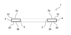
- the glass spacer 1 is ring-shaped and has two main surfaces 2a and 2b facing each other, an inner peripheral end face 3 and an outer peripheral end face 4.
- the main surface 2a is an annular surface having two concentric circles as outer and inner edges.
- the main surface 2b has the same shape and is concentric with the main surface 2a.
- the inner peripheral end surface 3 is a surface connecting the inner edge of the main surface 2a and the inner edge of the main surface 2b
- the outer peripheral end surface 4 is a surface connecting the outer edge of the main surface 2a and the outer edge of the main surface 2b.
- a chamfered surface may be formed at each of the connecting portions between the two main surfaces 2a and 2b and the inner peripheral end surface 3 and the connecting portion between the two main surfaces 2a and 2b and the outer peripheral end surface 4.
- the cross-sectional shape of the chamfered surface may be linear or arcuate.
- the two main surfaces 2a and 2b are surfaces that come into contact with the magnetic disk.
- the inner peripheral end surface 3 is a surface that contacts the spindle 107 of the HDD device 100 and is a wall surface that surrounds a hole with an inner diameter slightly larger than the outer diameter of the spindle 107 .
- the outer peripheral end surface 4 is a surface that does not contact the magnetic disk 105 or the spindle 107 .
- the dimensions of the glass spacer 1 may be appropriately changed according to the specifications of the HDD device 100 to be mounted.
- the inner diameter (diameter) is, for example, 24-26 mm
- the radial width is, for example, 2-5 mm
- the thickness is, for example, 0.5-3 mm.
- the width of the chamfered surface in the radial direction and the plate thickness direction is, for example, 0.01 to 0.5 mm.
- the glass spacer 1 has a ring-shaped glass substrate 20 and a film 22 covering the entire surface of the glass substrate 20 . That is, the presence of the film 22 prevents the surface of the glass substrate 20 from being exposed. Therefore, static electricity is less likely to accumulate on the glass spacer 1 . In addition, it is possible to prevent a part of the glass substrate 20 from turning into fine particles, generating dust, and adhering to the magnetic disk. It is preferable that the cross-sectional shape of the glass substrate 20 is a rectangle whose length in the radial direction is longer than the length in the thickness direction, because the glass substrate 20 can be easily floated during the formation of the film 22, which will be described later.
- the coefficient of thermal expansion of the glass substrate 20 is preferably approximately equal to that of the glass substrate of the magnetic disk.
- the material of the glass substrate 20 is not particularly limited, and examples thereof include aluminosilicate glass, soda lime glass, soda aluminosilicate glass, aluminoboron silicate glass, boron silicate glass, and quartz glass. In terms of crystallinity, either amorphous glass or crystallized glass may be used. Amorphous glass is preferable because it has a relatively high hardness and is easy to increase the surface smoothness.
- the glass substrate 20 is made of amorphous aluminosilicate glass, for example, silicon dioxide (SiO 2 ): 59 to 63% by mass, aluminum oxide (Al 2 O 3 ): 5 to 16% by mass, lithium oxide (Li 2 O ): 2 to 10% by mass, sodium oxide (Na 2 O): 2 to 12% by mass, and zirconium oxide (ZrO 2 ): 0 to 5% by mass.
- This glass is suitable for the glass substrate 20 because of its high rigidity and low coefficient of thermal expansion.
- the glass substrate 20 is made of soda-lime glass, for example, SiO 2 : 65 to 75% by mass, Al 2 O 3 : 1 to 6% by mass, CaO: 2 to 7% by mass, Na 2 O: 5 to 17% by mass. %, and ZrO 2 : 0 to 5% by mass.
- Amorphous aluminosilicate glass and soda-lime glass are suitable for the glass substrate 20 because they are relatively easy to grind and polish, and are easy to increase the surface smoothness.
- the material of the glass substrate 20 may be cut into a ring shape from a sheet glass manufactured by the float method, the down-draw method, or the like, may be molded from molten glass by the press method, or may be manufactured by the tube drawing method. It may be sliced from a glass tube.
- the glass substrate 20 is obtained by grinding and/or polishing the end face (the inner peripheral end face and the outer peripheral end face) and the main surface of the ring-shaped glass thus formed.
- the method of grinding the end face is not particularly limited, and for example, grinding can be performed with a formed grindstone containing diamond abrasive grains of #80 to #1000. At this time, the chamfered surface can be formed at the same time.
- the end face may be polished using a polishing brush having bristles such as nylon. These end surface processing can be performed by rotating both the ring-shaped glass and the formed grindstone or the polishing brush to bring them into contact with each other, similarly to the end surface processing of the magnetic disk glass substrate.
- chemical polishing may be performed using an etchant containing hydrofluoric acid or silicic hydrofluoric acid.
- the film 22 is a conductive film, and may be a film containing a conductive metal oxide or a film containing a conductive ceramic.
- the film 22 can be a film containing any of tin oxide (SnO 2 ), zinc oxide (ZnO), and titanium oxide (TiO 2 ).
- the film 22 may be FTO, which is tin oxide doped with fluorine, or AZO, which is zinc oxide doped with aluminum oxide (Al 2 O 3 ).
- the degree of conductivity of the film 22 may be appropriately determined as necessary, but for example, the surface resistivity at 22[° C.] is 10 8 [ ⁇ /sq] or less.
- the thickness of the film 22 is preferably 200 nm or less, more preferably less than 100 nm. If the thickness exceeds 200 nm, the manufacturing cost may become excessive. Moreover, when the thickness is 100 nm or more, the surface unevenness of the film 22 may become large. If the projecting portion of the film 22 is too large, when it comes into contact with the magnetic disk, part of the projecting portion may separate from the film 22 and generate fine particles, causing the magnetic head to crash. On the other hand, the thickness of the film 22 is preferably 5 nm or more, more preferably 10 nm or more, in order to prevent dust generation and ion elution from the substrate surface.
- the film thickness of the outer peripheral end surface 4 is thicker than the film thickness of the inner peripheral end surface 3 . Since the film thickness of the outer peripheral end face 4 is thicker than the film thickness of the inner peripheral end face 3, it becomes easier to prevent the above troubles.
- the film thickness of each surface can be, for example, the film thickness at the central portion of each surface.
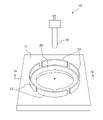
- the film forming apparatus 10 includes a plate 11 (also referred to as a mounting table) on which a ring-shaped glass substrate 20, which is an example of a ring-shaped base material, is mounted, a positioning member 12 provided on the plate 11, and a raw material for the film 22. and a housing (chamber) that accommodates them. Note that illustration of the housing is omitted in FIG.
- the plate 11 is, for example, a metal plate provided with heating means such as an electric heater, and can heat the glass substrate 20 mounted so as to be in contact with the upper surface (also referred to as mounting surface) of the plate 11 .
- the state in which the ring-shaped substrate such as the glass substrate 20 is mounted on the upper surface (mounting surface) of the plate 11 (mounting table) means that the ring-shaped substrate is in a floating state described later. It also includes a state of falling and riding on the upper surface of the plate 11 .
- the heating temperature of the glass substrate 20 may be appropriately adjusted according to the film to be formed, and is, for example, 300 to 600° C. when forming the conductive film 22 of tin oxide.
- the material of the plate 11 may be any material as long as it can withstand the heating temperature corresponding to the film to be formed. At least the area of the surface of the plate 11 that can come into contact with the glass substrate 20 is preferably flat so that it can be efficiently heated when it comes into contact with the glass substrate. Further, the surface roughness of the plate 11 is preferably 5 ⁇ m or less, more preferably 3 ⁇ m or less in terms of arithmetic mean roughness Ra. If the Ra exceeds 5 ⁇ m, the contact area with the glass substrate is reduced, making it difficult to heat quickly, and the surface of the glass substrate may be damaged when the glass substrate falls from the floating state. The above Ra can be measured, for example, with a stylus-type surface roughness tester.
- the plate 11 has, for example, a rectangular shape, and the length of each side is greater than the outer diameter of the glass substrate 20 . That is, the plate 11 has a size in which the entire glass substrate 20 can be accommodated.
- the positioning member 12 While the positioning member 12 is blowing the gas containing the raw material of the film 22 from the nozzle 13, the glass substrate 20 mounted on the upper surface of the plate 11 is projected from the predetermined range of the upper surface of the plate 11 by the air flow. provided to prevent It also has the role of maintaining a high concentration of the gas containing the raw material of the film 22 around the glass substrate 20 to reduce variations in film thickness over the entire surface of the glass substrate 20 and to increase the formation speed of the film 22. .
- the positioning member 12 is composed of one or a plurality of screens erected outside a predetermined range on the upper surface of the plate 11 so as to surround the predetermined range.
- the material of the screen is, for example, metal, glass, ceramics, or a combination of two or more of these materials.
- the predetermined range of the upper surface of the plate 11 means, for example, a circular range having a diameter approximately 3 to 50% larger than the outer diameter of the glass substrate 20 . It is more preferable that the predetermined range be a circular range having a diameter larger than the outer diameter of the glass substrate 20 by about 5 to 30%. Therefore, when the glass substrate 20 is placed within a predetermined range on the upper surface of the plate 11, there is space between the outer peripheral end surface of the glass substrate 20 and the inner surface of the positioning member 12 in the outer peripheral direction of the glass substrate 20. A space is at least partially defined therealong.
- the positioning member 12 is arranged at a predetermined distance from the outer peripheral end face of the glass substrate 20 (that is, with a predetermined gap).
- This gap is defined not only when the glass substrate 20 is placed on the upper surface of the plate 11 (the height from the plate 11 is assumed to be zero), but also when the glass substrate 20 is floated. It needs to be secured even when the height changes, but it does not necessarily have to be constant in the height direction. A film can be formed also on the outer peripheral end surface of the glass substrate 20 due to the presence of this gap.
- the positioning member 12 is composed of a plurality of screens, two adjacent screens are spaced apart. That is, a gap is formed between two adjacent screens.
- the size of the gap is not particularly limited as long as the glass substrate 20 floats stably. 1 to 15% of the circumferential length of the virtual circle whose radius is the distance to When the positioning member 12 is composed of a plurality of screens, it is preferable to use three or more screens. By doing so, the gaps can be arranged around the glass substrate 12 in a well-balanced manner, so that the floating stability can be improved.
- the shape of the positioning member 12 (more specifically, the shape of the wall surface of the positioning member 12 on the glass substrate 20 side) is a circle, arc, curve, straight line, polygonal line, Alternatively, it can have various shapes such as a shape in which these are combined.
- the height of the positioning member 12 may be appropriately determined according to the thickness of the glass substrate 20 and the height to be floated during film formation, and is, for example, 5 to 50 mm.
- a member may be further provided to prevent the glass substrate 20 from jumping over the positioning member 12 due to the airflow.
- a canopy projecting in the arrangement direction of the glass substrate 20 may be provided on the positioning member 12 .
- the shape of the eaves is preferably a shape that does not hinder the progress of the gas jetted from the nozzle 13 .
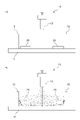
- the nozzle 13 is arranged above the plate 11 in the housing, and in a state where the glass substrate 20 is placed within a predetermined range on the upper surface of the plate 11, the central axis of the nozzle 13 (the central axis of ejection) are positioned so as to fit in the center hole of the glass substrate 20 .
- the central axis of the nozzle 13 is preferably vertical. Moreover, it is preferable that the central axis of the nozzle 13 passes through the center of the predetermined range. Then, from the nozzle 13 , the raw material of the film 22 is jetted together with gas such as air toward the center hole of the glass substrate 20 placed within a predetermined range on the upper surface of the plate 11 .
- the raw material of the film 22 becomes fine droplets (mist) and moves or floats within the housing.
- the injection pressure of the nozzle 13 can be set to 0.05 to 1.0 MPa, for example.
- a liquid obtained by dissolving a tin organic compound such as dibutyltin diacetate or dimethyltin dichloride in a solvent such as ethanol can be used as the raw material of the film 22 .
- the glass substrate 20 is placed on the top surface of the plate 11 within a predetermined range. That is, the glass substrate 20 is arranged inside the positioning member 12 . Then, by heating the plate 11 with an electric heater, the glass substrate 20 placed on the upper surface of the plate 11 is heated up to 400° C., for example.
- a gas containing raw materials for the film 22 is jetted from the nozzle 13 toward the hole in the center of the glass substrate 20. Then, as shown in FIG. The gas jetted from the nozzle 13 passes through the hole in the center of the glass substrate 20 and collides with the upper surface of the plate 11. Then, the gas flows along the upper surface of the plate 11 toward the radially outer side of the glass substrate 20, and the glass substrate It flows into a small gap between the bottom surface of 20 and the top surface of plate 11 . Thereby, the glass substrate 20 floats from the upper surface of the plate 11 .
- Part of the gas that has passed between the lower surface of the glass substrate 20 and the upper surface of the plate 11 passes through the gaps of the screens forming the positioning member 12 and flows to the outside of the positioning member 12, and the rest of the gas passes through the glass substrate. It flows upward along the inner surface of the positioning member 12 in the space between the outer peripheral end surface of the nozzle 20 and the inner surface of the positioning member 12 . That is, the gas injected from the nozzle 13 flows as indicated by the solid line arrow in FIG. 4(b). As a result, the glass substrate 20 floats from the plate 11, and the raw material mist of the film 22 floating in the housing adheres not only to the upper surface, the inner peripheral end surface, and the outer peripheral end surface of the glass substrate 20, but also to the lower surface.
- the mist of the raw material of the film 22 adheres to the entire surface of the glass substrate 20 .
- the solvent evaporates and the organic compound dissolved in the solvent undergoes a chemical reaction.
- a solid film 22 is formed on the entire surface of the glass substrate 20 .
- the temperature of the glass substrate 20 decreases due to floating away from the plate 11 and evaporation of the solvent adhering to the glass substrate 20 . Therefore, after the gas containing the material of the film 22 is injected from the nozzle 13 to float the glass substrate 20 from the plate 11 for a certain period of time, the injection from the nozzle 13 is stopped for a certain period of time. Thereby, the floating glass substrate 20 is landed on the upper surface of the plate 11, and the glass substrate 20 on which a part of the film 22 is formed is reheated.
- the temperature of the glass substrate 20 is maintained at a predetermined temperature and the glass substrate is heated.
- a film 22 having desired physical properties and thickness can be formed on the entire surface of the glass substrate 20 such that the surface of the glass substrate 20 is not exposed at all.
- a helical protrusion may be provided on the inner wall of the nozzle 13, and the nozzle 13 may be configured so that the gas containing the raw material of the film 22 is jetted in a spiral. is preferred.
- the upper surface, lower surface, A film can be formed on the inner peripheral end face and the outer peripheral end face at the same time.
- the film thickness can be easily controlled by intermittently jetting from the nozzle.
- the glass substrate 20 can be brought into contact with the gas containing the raw material of the film while the glass substrate 20 is floated without supporting the glass substrate 20 with a jig or the like, the film can be formed evenly. In addition, it becomes difficult for impurities to enter the film.
- the ring-shaped substrate repeats floating from the plate and landing on the plate multiple times. Then, the ring-shaped base material whose temperature has been lowered by rising from the heated plate is reheated by landing on the plate again. That is, the temperature and heating time of the ring-shaped substrate during film formation can be easily controlled. For example, in the case of forming a conductive tin oxide film, if the substrate temperature is too low, the chemical reaction of the organic compound, which is the raw material of the film, may be insufficient, resulting in insufficient film formation. Keeping it high is very important. That is, the method of the present invention is very suitable for a spray film forming method that requires high-temperature substrate heating.
- the predetermined range on the plate 11 is a circular range having a diameter approximately 3 to 50% larger than the outer diameter of the glass substrate 20, and the glass substrate 20 is placed within the predetermined range on the upper surface of the plate 11.
- a space is formed at least partially along the outer peripheral direction of the glass substrate 20 between the outer peripheral end surface of the glass substrate 20 and the inner surface of the positioning member 12 . Therefore, when the glass substrate 20 is floated from the plate 11 by the injection from the nozzle 13 , the glass substrate 20 finely vibrates or swings inside the positioning member 12 . By this vibration or rocking, it is possible to obtain the effect of reducing variations in film thickness on each surface of the glass substrate 20 .
- Example 1 A ring-shaped glass substrate 20 was placed on the upper surface of the plate 11 of the film forming apparatus 10, and the glass substrate 20 was heated.
- the specifications of the glass substrate 20 are an outer diameter of 32 mm, an inner diameter of 25 mm, and a thickness of 2 mm.
- the film forming apparatus 10 has a heatable mounting surface (plate) made of stainless steel and four arc-shaped screens (30 mm in height) of the same shape. They were arranged so that a space (corresponding to the above-mentioned "predetermined range") was formed, and a gap of 10 mm was provided between each other along the circumferential length of 90 degrees (see FIG. 3).
- the film thicknesses of the main surface 2a, the main surface 2b, the inner peripheral end surface 3, and the outer peripheral end surface 4 were 63 nm, 63 nm, 57 nm and 61 nm.
- the glass spacer 1 was obtained with an extremely small film thickness variation (maximum film thickness - minimum film thickness) of 6 nm for the four main surfaces of the glass spacer 1 .
- the film thickness of the inner peripheral end face 3 and the outer peripheral end face 4 was thinner than the film thickness of the main surfaces 2 a and 2 b, and the film thickness of the outer peripheral end face 4 was thicker than the film thickness of the inner peripheral end face 3 .
- there was no trace of holding by the holding member on the entire surface of the glass spacer 1 when the surface resistivity of the film 22 was measured, it was 10 8 [ ⁇ /sq] or less at 22 [°C]. If the film thickness variation rate of the four main surfaces of the glass spacer 1 is defined as (maximum film thickness - minimum film thickness)/(average film thickness) x 100 (%), then in the case of the glass spacer 1 It was about 9.8%.
- the film thickness variation rate is 30% or less, the film thickness distribution is small compared to the conventional film forming method in which the front and back are separately formed, so the film thickness can be reduced as a whole while ensuring the conductivity. It is preferable because the cost can be reduced by lowering the
- the film thickness variation rate is more preferably 25% or less, 20% or less, 15% or less, and 10% or less, in that order.
- the film formation variation rate in the conventional film formation method is calculated.
- the ratio of the film thicknesses of the main surface 2a, the main surface 2b, the inner peripheral end face 3, and the outer peripheral end face 4 is theoretically 1:1:2:2.
- the film thickness variation rate is 66.7%. Therefore, if the film thickness variation rate is 30% or less, it is half or less than the conventional one, so it can be said that the film thickness variation is sufficiently small.
- Example 2 a tin oxide film 22 was formed on the surface of the glass substrate 20 in the same manner as in Example 1 except that the spraying and heating operations were performed 100 times to 70 times.
- the film thicknesses of the four main surfaces were measured, the film thicknesses of the main surface 2a, the main surface 2b, the inner peripheral end face 3, and the outer peripheral end face 4 were 47 nm, 48 nm, 40 nm, and 45 nm, respectively.
- the film thickness variation (maximum film thickness - minimum film thickness) was 8 nm, and the film thickness variation rate defined above was about 17.8%, which was within a preferable range.
- the same results as in Example 1 were obtained with respect to the magnitude relationship between the film thicknesses of the four main surfaces, the presence or absence of traces of holding by the holding member, and the surface resistivity of the film 22 .
- Example 3 Further, a tin oxide film 22 was formed on the surface of the glass substrate 20 in the same manner as in Example 1 except that the spraying and heating operations were performed 100 times to 30 times.
- the film thicknesses of the four main surfaces were measured, the film thicknesses of the main surface 2a, the main surface 2b, the inner peripheral end surface 3, and the outer peripheral end surface 4 were 25 nm, 25 nm, 19 nm, and 23 nm, respectively.
- the film thickness variation (maximum film thickness - minimum film thickness) was 6 nm, and the film thickness variation rate defined above was about 26.8%, which was within a preferable range.
- the same results as in Example 1 were obtained with respect to the magnitude relationship between the film thicknesses of the four main surfaces, the presence or absence of traces of holding by the holding member, and the surface resistivity of the film 22 .
- a plurality of glass spacers 1 fabricated by the method of Example 1 were sandwiched between a plurality of magnetic disks as shown in FIG. 1 to fabricate an HDD device. There were no abnormalities due to fine particles, etc., and it operated normally. Similar results were also obtained for the glass spacers 1 produced in Examples 2 and 3.
- the cross-sectional shape of the glass substrate 20 is rectangular in the above embodiment, it is not limited to this.
- the cross-sectional shape of the glass substrate 20 may be circular or elliptical, for example, as long as it floats by jetting. From the viewpoint of the flying property of the glass substrate 20 when sprayed, it is preferable that the length in the radial direction is longer than the length in the thickness direction in the cross section of the glass substrate 20 .
- the glass spacer 1 used in the HDD device was given as an example of the ring-shaped object, but it is not limited to this, and the ring-shaped object may be, for example, a washer or packing.
- the ring-shaped glass substrate 20 was given as an example of the ring-shaped base material, but it is not limited to this.
- the ring-shaped substrate may be, for example, a ring-shaped metal substrate made of metal such as aluminum (including aluminum alloy), stainless steel, titanium (including titanium alloy), PDAP (diallyl phthalate), PAI ( Polyamideimide), PTFE (polytetrafluoroethylene), PPS (polyphenylene sulfide), PI (polyimide), SI (silicone), PEEK (polyetheretherketone), or the like.
- it may be a ring-shaped ceramic substrate made of ceramic such as alumina, mullite, zirconia, or the like.
- the material of the ring-shaped substrate may be a composite of two or more materials selected from glass, ceramics, metals and resins.
- the film may then be, for example, a film of paint or other functional film that requires substrate heating.
- the positioning member 12 may not be composed of a plurality of screens, and may be composed of a single annular screen erected so as to surround the outer periphery of a predetermined range. In other words, it is not necessary to form a gap between two adjacent screens as in the above embodiment.
- one or more holes may be provided in one of the annular partitions. This opening may be provided in the lower part of the screen so as to include the upper surface of the plate 11, or may be provided in the upper part of the screen so that the upper part of the opening is open to the air. In other words, the opening may be formed as a notch in the lower or upper edge of the screen.
- the opening may be provided in the middle of the screen in the height direction so as not to contact the lower and upper ends of the screen.
- the gap or opening is too small or not provided at all, the ring-shaped base material may get over the screen when the gas is jetted. It is necessary to make adjustments such as weakening the If the height of the screen is high, it may become difficult to remove the ring-shaped object from the inside of the screen after film formation.
- the positioning member 12 is formed with a gap or an opening for allowing part of the gas injected from the nozzle to escape to the outside of the positioning member 12 .
- the area of the gap or opening is preferably 10 to 90%, more preferably 20 to 70%, of the area of the screen when none of them are provided (in the case of a single annular screen). .
- a conical protrusion may be provided within a predetermined range on the upper surface of the plate 11, for example.
- the convex portion may be arranged such that the top of the convex portion protrudes from the central hole of the glass substrate 20 when the glass substrate 20 is arranged within a predetermined range.
- the gas easily flows into the gap between the lower surface of the glass substrate 20 and the upper surface of the plate 11, and the glass substrate 11 is formed. 20 from the plate 11 can be improved.
- the predetermined range on the plate 11 may be a circular range having the same diameter as the outer diameter of the glass substrate 20, and when the glass substrate 20 is arranged within the predetermined range of the plate 11, the outer circumference of the glass substrate 20 may be a circular range.
- a space may not be formed between the end surface and the inner surface of the positioning member 12 .
- the outer peripheral end surface of the glass substrate 20 and the positioning member 12 A space is preferably formed at least partially between the inner surface.
- the film forming apparatus 10 does not have to have a housing structure.
- the housing (chamber) that accommodates the plate 11, the positioning member 12, and the nozzles 13 may not be provided.
- the positioning member 12 As an example of the positioning member 12, a plurality of screens erected on the upper surface of the plate 11 are cited, but the positioning member 12 is not limited to this.
- a conical protrusion may be provided within a predetermined range on the upper surface of the plate 11.
- FIG. 5(a) when the glass substrate 20 is placed within a predetermined range on the upper surface of the plate 11, the top of the projection extends from the central hole of the glass substrate 20. You may arrange
- the gas containing the raw material of the film from the nozzle 13 toward the top of the projection by injecting the gas containing the raw material of the film from the nozzle 13 toward the top of the projection, the gas spreads over the lower surface of the glass substrate 20 and the upper surface of the plate 11. It becomes easy to flow into the gap between the glass substrates 20, and the floatability of the glass substrate 20 from the plate 11 can be improved. Further, even if the glass substrate 20 floated from the plate 11 vibrates or swings while the gas containing the raw material of the film 22 is being sprayed from the nozzle 13, the inner peripheral end face of the glass substrate 20 is caught on the convex portion. Therefore, it is possible to prevent the glass substrate 20 from protruding from the predetermined range.
- recesses or grooves may be provided on the plate 11 to the extent that the heating of the glass substrate 20 is not hindered.
- a plurality of recesses may be arranged side by side in the circumferential direction and/or radial direction of the circle.
- a gas containing the material of the film 22 is blown from the nozzle 13 provided above the glass substrate 20 toward the central hole of the glass substrate 20.
- the glass substrate 20 is floated from the upper surface of the plate 11 by attaching the glass substrate 20, the method for floating the glass substrate 20 is not limited to this.
- gas containing raw materials for the film 22 is supplied from a plurality of nozzles 13 opening at least toward the lower surface of the glass substrate 20 placed on the upper surface of the plate 11 . may be blown to float the glass substrate 20 from the upper surface of the plate 11 .
- the injection pressure of the gas containing the material of the film 22 may be such that the glass substrate 20 floats above the upper surface of the plate 11, and may be, for example, 0.01 to 1.0 MPa. Further, the specifications of the positioning member 12 can be the same as those of the above-described embodiment.
- a top cover 14 may be provided above the positioning member 12 from the viewpoint of uniforming the film thickness distribution and improving the film forming speed by increasing the concentration of the gas containing the raw material No. 22 .
- the positioning member 12 is composed of a single annular partition without an opening and the film forming space defined by the plate 11, the positioning member 12, and the upper lid 14 is sealed, the material of the film 22 is is prevented from being ejected from the plurality of nozzles 13.
- the upper lid 14 may be provided with an opening for releasing the gas containing the raw material of the film 22 from the film-forming space.
- the ratio of the area of the opening in the upper lid 14 is preferably 50% or less, more preferably 30% or less, from the viewpoint of uniforming the film thickness distribution and improving the film formation speed.
- the glass substrate 20 can be repeatedly lifted from the upper surface of the plate 11 and landed on the upper surface of the plate 11 a plurality of times.
- a film 22 is formed on the surface of the glass substrate 20 while the glass substrate 20 is floating above the upper surface of the plate 11, but the temperature of the glass substrate 20 decreases.
- the temperature of the glass substrate 20 becomes too low, the chemical reaction of the raw materials of the film 22 becomes insufficient, and the film 22 may not be formed. After the glass substrate 20 is lifted from the upper surface of the plate 11 and then landed on the upper surface of the plate 11, the temperature of the glass substrate 20 that has decreased due to the floating can be recovered.
- the plate 11 is provided with a heating means such as an electric heater, and the glass substrate 20 is heated by contact with the plate 11, but the present invention is not limited to this.
- the plate 11 may not have a heating means, and the glass substrate 20 may be heated in a non-contact manner using, for example, infrared rays.
- the injection pressure may be gradually lowered when stopping the injection of the gas containing the raw material. By doing so, damage to the glass substrate 20 and the film 22 when the glass substrate 20 falls onto the plate 11 can be suppressed.
- films may be formed on a plurality of glass substrates 20 on the plate 11 at the same time.
- the plate 11 has a large area, and the positioning members 12 and the nozzles 13 can be provided according to the number of glass substrates 20 on which films are to be formed.
- the nozzle 13 used in the above embodiment is merely an example, and the nozzle outlet may be processed so that the gas is annularly ejected along the central axis of the nozzle 13 .
- the nozzle 13 may have a plurality of gas ejection ports.
- a plurality of ejection ports for ejecting gas in the horizontal direction are provided on the side surface of the nozzle 13, and the nozzle 13 is installed at a height position close to the plate 11 and at the center of a predetermined range, so that the inner peripheral end surface of the glass substrate 20 or the The gas may be blown toward the portion of the inner peripheral end surface that contacts the plate 11 .
Abstract
This method for producing a ring-shaped object (1) includes placing a ring-shaped substrate (20) on a plate (11), and spraying a coating-raw-material-containing gas into the hole in the center of the ring-shaped substrate (20) placed on the plate (11) from above the ring-shaped substrate (20) to raise the ring-shaped substrate (20) from the plate (11) and form a film (22) on the surface of the ring-shaped substrate (20).
Description
本発明は、リング状物体の全表面に対するスプレー成膜によるリング状物体の製造方法、成膜装置、リング状物体、及びハードディスクドライブ装置に関する。
The present invention relates to a method for manufacturing a ring-shaped object by spray film formation on the entire surface of the ring-shaped object, a film forming apparatus, a ring-shaped object, and a hard disk drive.
近年のクラウドコンピューティングの隆盛に伴って、クラウド向けのデータセンターでは記憶容量の大容量化のために多くのハードディスクドライブ装置(以下、HDD装置ともいう)が用いられている。
With the recent prosperity of cloud computing, many hard disk drives (hereinafter also referred to as HDD devices) are used in cloud data centers to increase storage capacity.
HDD装置には、磁気ディスク同士の間に、磁気ディスク同士を離間させて保持するためのリング形状のスペーサが設けられている。スペーサは、磁気ディスク同士が接触せず、高精度に所定の位置に離間して配置されるように機能する。スペーサの材料としては、従来、導電性があり、製造コストの低い金属材料が用いられてきた。ところで、磁気ディスク用の基板としてガラス基板を用いる場合など、スペーサと磁気ディスク用基板のそれぞれの材料の線膨張係数が異なる場合、スペーサと磁気ディスクとは互いに接触しているので、HDD装置内の温度の変化に伴って、スペーサと磁気ディスクとの間で熱膨張の差が生じる。この結果、磁気ディスクに撓みが生じ、磁気ヘッドの浮上性が悪化する場合がある。磁気ヘッドの浮上性が悪化することは、HDD装置における磁気ディスクの読み取り及び書き込みの点から好ましくない。この問題は、高記録密度化が進むほど影響が大きくなる。
HDD devices are provided with ring-shaped spacers between the magnetic disks to hold the magnetic disks apart. The spacer functions so that the magnetic disks do not come into contact with each other and are spaced apart at predetermined positions with high accuracy. As a spacer material, conventionally, a metal material having electrical conductivity and low manufacturing cost has been used. By the way, when a glass substrate is used as the substrate for the magnetic disk, for example, when the materials of the spacer and the substrate for the magnetic disk have different coefficients of linear expansion, the spacer and the magnetic disk are in contact with each other. A difference in thermal expansion occurs between the spacer and the magnetic disk as the temperature changes. As a result, the magnetic disk is flexed, and the flying performance of the magnetic head may deteriorate. Deterioration of the flying property of the magnetic head is not preferable from the viewpoint of reading and writing of the magnetic disk in the HDD device. This problem becomes more serious as the recording density increases.
このため、近年、磁気ディスク用基板としてガラス基板を用いる場合に対応させる(線膨張係数を近づける)ため、あるいは従来より軽くて高剛性のスペーサとするため、ガラス製スペーサ(以下、ガラススペーサという)を用いることが検討されている。しかし、ガラスは絶縁体であるため、高速回転する磁気ディスク及びガラススペーサと、空気との摩擦等により、磁気ディスクあるいはスペーサ上に静電気が溜まり易い。磁気ディスクやスペーサが帯電すると、異物や微粒子を吸着し易くなるほか、溜まった静電気の磁気ヘッドへの放電により、磁気ヘッドの記録素子や再生素子が破壊されることがあるので好ましくない。
For this reason, in recent years, glass spacers (hereinafter referred to as glass spacers) have been developed in order to correspond to the case where a glass substrate is used as a substrate for a magnetic disk (to bring the coefficient of linear expansion closer), or to make the spacer lighter and more rigid than before. is being considered. However, since glass is an insulator, static electricity tends to accumulate on the magnetic disk or spacer due to friction between the magnetic disk and glass spacer rotating at high speed and the air. When the magnetic disk or spacer is charged, it is not preferable because foreign matter and fine particles are likely to be attracted to the magnetic disk and the magnetic head, and the accumulated static electricity may be discharged to the magnetic head, thereby destroying the recording element and the reproducing element of the magnetic head.
これに対して、ガラススペーサの少なくとも磁気ディスクとの当接面及び内周面に、膜厚0.1~3μmの導電性セラミック膜を被覆したガラススペーサが知られている(特許文献1)。これにより、磁気ディスクに帯電した静電気を効率よく逃がすことができ、当接面をほとんど摩耗させることがないとされている。
On the other hand, a glass spacer is known in which at least the contact surface with the magnetic disk and the inner peripheral surface of the glass spacer are coated with a conductive ceramic film having a thickness of 0.1 to 3 μm (Patent Document 1). It is said that this allows the static electricity charged on the magnetic disk to be released efficiently, and hardly wears the contact surface.
上記ガラススペーサを製造する際の成膜には、PVD(Physical Vapor Deposition)法、CVD(Chemical Vapor Deposition)法等が用いられる。しかし、これらの成膜方法を用いる場合、一般的には、スペーサを保持する部材(支持部材)がスペーサと接触する部分については成膜できないという問題がある。このため、保持部材による保持のためにスペーサの表面の一部が成膜されずに露出し、露出した部分からガラスの欠片が微粒子となって発塵する場合があった。また、露出部分を完全に無くすために、一度成膜したスペーサを成膜装置から取り出し、成膜された領域を保持部材で保持しつつ二度目の成膜を行うことも可能ではある。しかし、二度の成膜を行うため、保持部材と接触した場所と、それ以外の場所とで膜厚ムラが生じるという問題があった。さらに、成膜工程が煩雑となり、製造コストが増加するという問題があった。
A PVD (Physical Vapor Deposition) method, a CVD (Chemical Vapor Deposition) method, or the like is used for film formation when manufacturing the glass spacer. However, when these film forming methods are used, there is generally a problem that the film cannot be formed on the portion where the spacer-holding member (supporting member) contacts the spacer. For this reason, a part of the surface of the spacer is exposed without forming a film due to the holding by the holding member, and glass fragments from the exposed part may become fine particles and generate dust. Further, in order to completely eliminate the exposed portion, it is possible to remove the once-film-formed spacer from the film-forming apparatus, hold the film-formed region with a holding member, and perform the second film formation. However, since the film is formed twice, there is a problem that the film thickness is uneven between the part in contact with the holding member and the other part. Furthermore, there is a problem that the film formation process becomes complicated and the manufacturing cost increases.
本発明は、上記のような課題を解決するためになされたものであり、リング状物体の製造方法において、リング状物体の表面の膜厚ムラを抑制しつつ、成膜プロセスの生産性を向上させることが可能な技術を提供することを目的とする。
The present invention has been made to solve the above-described problems, and in a method for manufacturing a ring-shaped object, the productivity of the film formation process is improved while suppressing film thickness unevenness on the surface of the ring-shaped object. The purpose is to provide a technology that enables
本発明の第1の態様に従えば、リング状物体の製造方法であって、
リング状基材をプレートに載置することと、
前記プレートに載置された前記リング状基材の上方から前記リング状基材の中央の穴に被覆原料を含む気体を噴き付けて、前記リング状基材を前記プレートから浮上させて前記リング状基材の表面に膜を形成することとを含む、リング状物体の製造方法が提供される。 According to a first aspect of the present invention, a method for manufacturing a ring-shaped object, comprising:
placing the ring-shaped substrate on the plate;
A gas containing a coating raw material is sprayed from above the ring-shaped substrate placed on the plate into a hole in the center of the ring-shaped substrate to float the ring-shaped substrate from the plate to form the ring-shaped substrate. and forming a film on a surface of a substrate.
本発明の第1の態様に従うリング状物体の製造方法において、前記プレートが、加熱されたプレートであってもよい。
In the method for manufacturing a ring-shaped object according to the first aspect of the present invention, the plate may be a heated plate.
本発明の第1の態様に従うリング状物体の製造方法において、前記噴き付けを複数回行うことにより、前記リング状基材を前記プレートから浮上させることと、前記プレートに着地させることとを複数回繰り返してもよい。
In the method for manufacturing a ring-shaped object according to the first aspect of the present invention, by performing the spraying a plurality of times, the ring-shaped base material is lifted from the plate and landed on the plate a plurality of times. You can repeat.
本発明の第1の態様に従うリング状物体の製造方法において、前記被覆原料を含む気体の噴射圧力は、0.05~1.0MPaであってもよい。
In the method for manufacturing a ring-shaped object according to the first aspect of the present invention, the injection pressure of the gas containing the coating raw material may be 0.05-1.0 MPa.
本発明の第1の態様に従うリング状物体の製造方法において、前記リング状基材の材料はガラス、セラミックス、金属、樹脂のいずれか一つを含んでもよい。
In the method for manufacturing a ring-shaped object according to the first aspect of the present invention, the material of the ring-shaped substrate may include any one of glass, ceramics, metal, and resin.
本発明の第1の態様に従うリング状物体の製造方法において、前記膜は導電性の膜であってもよく、導電性の金属酸化物を含む膜であってもよい。
In the method for manufacturing a ring-shaped object according to the first aspect of the present invention, the film may be a conductive film or a film containing a conductive metal oxide.
本発明の第1の態様に従うリング状物体の製造方法において、前記リング状物体はハードディスクドライブ用スペーサであってもよい。
In the method for manufacturing a ring-shaped object according to the first aspect of the present invention, the ring-shaped object may be a hard disk drive spacer.
本発明の第2の態様に従えば、リング状物体の製造方法であって、
リング状基材を載置台に載置して加熱する加熱処理と、
被覆原料を含む気体を前記リング状基材に噴き付けることによって前記リング状基材を前記載置台から浮上させて前記リング状基材の表面に膜を形成する膜形成処理とを含む、リング状物体の製造方法が提供される。 According to a second aspect of the present invention, a method for manufacturing a ring-shaped object, comprising:
A heat treatment in which the ring-shaped base material is placed on a mounting table and heated;
and a film forming process for forming a film on the surface of the ring-shaped substrate by spraying a gas containing a coating material onto the ring-shaped substrate so as to float the ring-shaped substrate from the mounting table. A method of manufacturing an object is provided.
本発明の第3の態様に従えば、成膜装置であって、
リング状基材が載置されるプレートと、
前記プレートに設けられ、前記リング状基材を前記プレート上の所定範囲内に位置決めする位置決め部材と、
前記プレートの上方に設けられ、前記部材によって位置決めされた前記リング状基材の中央の穴に被覆原料を含む気体を噴き付けるノズルとを備える成膜装置が提供される。 According to a third aspect of the present invention, a film forming apparatus comprising:
a plate on which the ring-shaped substrate is placed;
a positioning member provided on the plate for positioning the ring-shaped substrate within a predetermined range on the plate;
and a nozzle provided above the plate for spraying a gas containing the coating raw material into the central hole of the ring-shaped substrate positioned by the member.
本発明の第3の態様に従う成膜装置において、前記位置決め部材は、前記プレートにおける前記所定範囲の外側に立設された少なくとも1つの衝立であってもよい。
In the film forming apparatus according to the third aspect of the present invention, the positioning member may be at least one screen erected outside the predetermined range on the plate.
本発明の第3の態様に従う成膜装置において、前記衝立は複数であってもよく、そのうち隣り合う二つの衝立は、前記所定範囲を囲むように離間して設けられていてもよい。
In the film forming apparatus according to the third aspect of the present invention, there may be a plurality of said screens, and two adjacent screens among them may be spaced apart so as to surround said predetermined range.
本発明の第3の態様に従う成膜装置は、さらに、前記プレートに凸部が設けられていてもよく、前記凸部は、前記リング状基材が前記所定範囲内に位置決めされた状態において、前記リング状基材の中央の穴から突出してもよい。
In the film forming apparatus according to the third aspect of the present invention, the plate may be further provided with a convex portion, and the convex portion, when the ring-shaped substrate is positioned within the predetermined range, It may protrude from a hole in the center of the ring-shaped substrate.
本発明の第3の態様に従う成膜装置において、前記位置決め部材は、前記プレートに設けられた凸部であってもよく、前記リング状基材は、前記リング状基材の中央の穴から前記凸部が突出するように前記プレートに配置されることにより、前記所定範囲内に位置決めされてもよい。
In the film forming apparatus according to the third aspect of the present invention, the positioning member may be a convex portion provided on the plate, and the ring-shaped substrate may extend from the center hole of the ring-shaped substrate to the Positioning within the predetermined range may be achieved by arranging the plate so that the convex portion protrudes.
本発明の第3の態様に従う成膜装置は、さらに、前記プレートを加熱するヒータを備えてもよい。
The film forming apparatus according to the third aspect of the present invention may further include a heater for heating the plate.
本発明の第4の態様に従えば、リング状物体であって、
互いに対向する第1主表面及び第2主表面と、外周端面と、内周端面とを有するリング状基材と、
前記リング状基材の全面に形成された膜とを備え、
前記外周端面における膜厚は、前記内周端面における膜厚よりも厚いリング状物体が提供される。 According to a fourth aspect of the present invention, a ring-shaped object,
a ring-shaped substrate having a first main surface and a second main surface facing each other, an outer peripheral end face, and an inner peripheral end face;
A film formed on the entire surface of the ring-shaped base material,
A ring-shaped object is provided in which the film thickness on the outer peripheral end face is thicker than the film thickness on the inner peripheral end face.
本発明の第4の態様に従うリング状物体において、前記第1主表面及び第2主表面における膜厚は、前記外周端面における膜厚よりも厚くてもよい。
In the ring-shaped object according to the fourth aspect of the present invention, the film thickness on the first main surface and the second main surface may be thicker than the film thickness on the outer peripheral end face.
本発明の第4の態様に従うリング状物体において、前記リング状基材の材料はガラス、セラミックス、金属、樹脂のいずれか一つを含んでもよい。
In the ring-shaped object according to the fourth aspect of the present invention, the material of the ring-shaped substrate may include any one of glass, ceramics, metal, and resin.
本発明の第4の態様に従うリング状物体において、前記膜は導電性の膜であってもよく、導電性の金属酸化物を含む膜であってもよい。
In the ring-shaped object according to the fourth aspect of the present invention, the film may be a conductive film or a film containing a conductive metal oxide.
本発明の第4の態様に従うリング状物体は、ハードディスクドライブ用スペーサであってもよい。
The ring-shaped object according to the fourth aspect of the present invention may be a hard disk drive spacer.
本発明の第5の態様に従えば、本発明の第4の態様に従うリング状物体と、磁気ディスクと、磁気ヘッドとを含むハードディスクドライブ装置が提供される。
According to a fifth aspect of the present invention, there is provided a hard disk drive including a ring-shaped object according to the fourth aspect of the present invention, a magnetic disk, and a magnetic head.
本発明によれば、リング状物体の製造方法において、リング状物体の表面の膜厚ムラを抑制しつつ、成膜プロセスの生産性を向上させることができる。
According to the present invention, in the method for manufacturing a ring-shaped object, it is possible to improve the productivity of the film formation process while suppressing film thickness unevenness on the surface of the ring-shaped object.
まず、本発明の製造方法により製造されたリング状物体の一例である、HDD装置に用いられるガラススペーサについて説明する。
First, a glass spacer used in an HDD device, which is an example of a ring-shaped object manufactured by the manufacturing method of the present invention, will be described.
図1(a)に示されるように、HDD装置100は、主に、複数枚のガラススペーサ1と、複数枚の磁気ディスク105と、複数の磁気ヘッド106と、スピンドル107と、スピンドルモータ108とを備える。HDD装置100において、ガラススペーサ1は、複数枚の磁気ディスク105をそれぞれ高精度に所定の位置に離間させて保持するため、隣り合う磁気ディスク105の間に配置される。そして、磁気ディスク105とガラススペーサ1とは、交互に重ねられた状態で、スピンドル107に挿通される。なお、HDD装置100において、最上層の磁気ディスク105の上面と接するガラススペーサ1が設けられてもよく、最下層の磁気ディスク105の下面と接するガラススペーサ1が設けられてもよい。
As shown in FIG. 1A, the HDD device 100 mainly includes a plurality of glass spacers 1, a plurality of magnetic disks 105, a plurality of magnetic heads 106, a spindle 107, and a spindle motor 108. Prepare. In the HDD device 100, the glass spacer 1 is arranged between adjacent magnetic disks 105 in order to hold the plurality of magnetic disks 105 apart from each other at predetermined positions with high accuracy. The magnetic disks 105 and the glass spacers 1 are alternately stacked and inserted into the spindle 107 . In the HDD device 100, the glass spacer 1 may be provided in contact with the upper surface of the magnetic disk 105 in the uppermost layer, or the glass spacer 1 may be provided in contact with the lower surface of the magnetic disk 105 in the lowermost layer.
図1(b)に示されるように、ガラススペーサ1はリング形状であり、互いに対向する二つの主表面2a、2b、内周端面3、及び外周端面4を備える。主表面2aは二つの同心円を外縁及び内縁として有する、円環形状の面である。主表面2bは、主表面2aと同形状であり且つ同心である。内周端面3は、主表面2aの内縁と主表面2bの内縁とを接続する面であり、外周端面4は、主表面2aの外縁と主表面2bの外縁とを接続する面である。なお、二つの主表面2a、2bと内周端面3との接続部、及び、二つの主表面2a、2bと外周端面4との接続部にはそれぞれ、面取面が形成されてもよい。この場合、面取面の断面形状は直線状であってもよく、円弧状であってもよい。二つの主表面2a、2bは、磁気ディスクと接する面である。内周端面3は、HDD装置100のスピンドル107と接する面であり、スピンドル107の外径よりも僅かに大きい内径の孔を囲む壁面である。外周端面4は、磁気ディスク105ともスピンドル107とも接しない面である。
As shown in FIG. 1(b), the glass spacer 1 is ring-shaped and has two main surfaces 2a and 2b facing each other, an inner peripheral end face 3 and an outer peripheral end face 4. The main surface 2a is an annular surface having two concentric circles as outer and inner edges. The main surface 2b has the same shape and is concentric with the main surface 2a. The inner peripheral end surface 3 is a surface connecting the inner edge of the main surface 2a and the inner edge of the main surface 2b, and the outer peripheral end surface 4 is a surface connecting the outer edge of the main surface 2a and the outer edge of the main surface 2b. A chamfered surface may be formed at each of the connecting portions between the two main surfaces 2a and 2b and the inner peripheral end surface 3 and the connecting portion between the two main surfaces 2a and 2b and the outer peripheral end surface 4. In this case, the cross-sectional shape of the chamfered surface may be linear or arcuate. The two main surfaces 2a and 2b are surfaces that come into contact with the magnetic disk. The inner peripheral end surface 3 is a surface that contacts the spindle 107 of the HDD device 100 and is a wall surface that surrounds a hole with an inner diameter slightly larger than the outer diameter of the spindle 107 . The outer peripheral end surface 4 is a surface that does not contact the magnetic disk 105 or the spindle 107 .
ガラススペーサ1の寸法は、搭載されるHDD装置100の仕様によって適宜変更すればよいが、公称3.5インチ型のHDD装置向けであれば、外径(直径)は例えば30~34mmであり、内径(直径)は例えば24~26mmであり、半径方向の幅は例えば2~5mmであり、厚さは例えば0.5~3mmである。また、面取面が形成される場合、面取面の半径方向及び板厚方向の幅は、それぞれ例えば0.01~0.5mmである。
The dimensions of the glass spacer 1 may be appropriately changed according to the specifications of the HDD device 100 to be mounted. The inner diameter (diameter) is, for example, 24-26 mm, the radial width is, for example, 2-5 mm, and the thickness is, for example, 0.5-3 mm. Further, when the chamfered surface is formed, the width of the chamfered surface in the radial direction and the plate thickness direction is, for example, 0.01 to 0.5 mm.
図2に示されるように、ガラススペーサ1は、リング形状をしたガラス基板20と、ガラス基板20の全表面を覆う膜22とを有する。すなわち、膜22の存在により、ガラス基板20の表面は露出しない。このため、ガラススペーサ1には、静電気が溜まりにくい。また、ガラス基板20の一部が微粒子となって発塵し、磁気ディスクに付着することを防ぐことができる。そして、ガラス基板20の断面形状は、半径方向の長さが厚み方向の長さよりも長い矩形であると、後述する膜22の形成時にガラス基板20を浮上させやすいので好ましい。
As shown in FIG. 2, the glass spacer 1 has a ring-shaped glass substrate 20 and a film 22 covering the entire surface of the glass substrate 20 . That is, the presence of the film 22 prevents the surface of the glass substrate 20 from being exposed. Therefore, static electricity is less likely to accumulate on the glass spacer 1 . In addition, it is possible to prevent a part of the glass substrate 20 from turning into fine particles, generating dust, and adhering to the magnetic disk. It is preferable that the cross-sectional shape of the glass substrate 20 is a rectangle whose length in the radial direction is longer than the length in the thickness direction, because the glass substrate 20 can be easily floated during the formation of the film 22, which will be described later.
ガラス基板20が有する熱膨張係数は、磁気ディスクのガラス基板の熱膨張係数と略等しいことが好ましい。ガラス基板20の材質は特に限定されるものではなく、アルミノシリケートガラス、ソーダライムガラス、ソーダアルミノケイ酸ガラス、アルミノボロンシリケートガラス、ボロンシリケートガラス、石英ガラス等が挙げられる。また、結晶性の観点では、アモルファスガラス、結晶化ガラスのいずれでもよい。なお、アモルファスガラスは、硬度が比較的高い上に表面平滑度を高め易い点で好ましい。
The coefficient of thermal expansion of the glass substrate 20 is preferably approximately equal to that of the glass substrate of the magnetic disk. The material of the glass substrate 20 is not particularly limited, and examples thereof include aluminosilicate glass, soda lime glass, soda aluminosilicate glass, aluminoboron silicate glass, boron silicate glass, and quartz glass. In terms of crystallinity, either amorphous glass or crystallized glass may be used. Amorphous glass is preferable because it has a relatively high hardness and is easy to increase the surface smoothness.
ガラス基板20をアモルファスのアルミノシリケートガラスで構成する場合、例えば、二酸化ケイ素(SiO2):59~63質量%、酸化アルミニウム(Al2O3):5~16質量%、酸化リチウム(Li2O):2~10質量%、酸化ナトリウム(Na2O):2~12質量%、酸化ジルコニウム(ZrO2):0~5質量%を成分とするガラスを用いることができる。このガラスは剛性が高く、熱膨張係数が低い点で、ガラス基板20に好適である。ガラス基板20をソーダライムガラスで構成する場合、例えば、SiO2:65~75質量%、Al2O3:1~6質量%、CaO:2~7質量%、Na2O:5~17質量%、ZrO2:0~5質量%を成分とするアモルファスのガラスを用いることができる。アモルファスのアルミノシリケートガラスやソーダライムガラスは、比較的研削や研磨が容易であり、表面平滑度を高め易い点で、ガラス基板20に適している。
When the glass substrate 20 is made of amorphous aluminosilicate glass, for example, silicon dioxide (SiO 2 ): 59 to 63% by mass, aluminum oxide (Al 2 O 3 ): 5 to 16% by mass, lithium oxide (Li 2 O ): 2 to 10% by mass, sodium oxide (Na 2 O): 2 to 12% by mass, and zirconium oxide (ZrO 2 ): 0 to 5% by mass. This glass is suitable for the glass substrate 20 because of its high rigidity and low coefficient of thermal expansion. When the glass substrate 20 is made of soda-lime glass, for example, SiO 2 : 65 to 75% by mass, Al 2 O 3 : 1 to 6% by mass, CaO: 2 to 7% by mass, Na 2 O: 5 to 17% by mass. %, and ZrO 2 : 0 to 5% by mass. Amorphous aluminosilicate glass and soda-lime glass are suitable for the glass substrate 20 because they are relatively easy to grind and polish, and are easy to increase the surface smoothness.
ガラス基板20の素材は、フロート法やダウンドロー法等により製造した板状ガラスからリング状に切り出されたものでもよく、プレス法により熔融ガラスから成型されたものでもよく、管引き法で製造したガラス管からスライスされたものでもよい。このように成形されたリング状ガラスの端面(内周端面や外周端面)や主表面に対し、研削及び/又は研磨を施すことにより、ガラス基板20が得られる。
The material of the glass substrate 20 may be cut into a ring shape from a sheet glass manufactured by the float method, the down-draw method, or the like, may be molded from molten glass by the press method, or may be manufactured by the tube drawing method. It may be sliced from a glass tube. The glass substrate 20 is obtained by grinding and/or polishing the end face (the inner peripheral end face and the outer peripheral end face) and the main surface of the ring-shaped glass thus formed.
端面に対する研削の方法は特に限定されるものではなく、例えば、#80~#1000のダイヤモンド砥粒を含む総型砥石により研削を行うことができる。このとき、同時に面取面を形成することができる。また、ナイロン等の毛材を備えた研磨ブラシを用いて端面の研磨を行ってもよい。これらの端面加工は、磁気ディスク用ガラス基板の端面加工と同様に、リング状ガラスと、総型砥石や研磨ブラシとの双方を回転させながら接触させることにより実行できる。また、フッ酸やケイフッ酸を含むエッチング液を用いて化学的に研磨してもよい。
The method of grinding the end face is not particularly limited, and for example, grinding can be performed with a formed grindstone containing diamond abrasive grains of #80 to #1000. At this time, the chamfered surface can be formed at the same time. Alternatively, the end face may be polished using a polishing brush having bristles such as nylon. These end surface processing can be performed by rotating both the ring-shaped glass and the formed grindstone or the polishing brush to bring them into contact with each other, similarly to the end surface processing of the magnetic disk glass substrate. Alternatively, chemical polishing may be performed using an etchant containing hydrofluoric acid or silicic hydrofluoric acid.
膜22は、導電性の膜であり、導電性の金属酸化物を含む膜であってもよく、導電性のセラミックスを含む膜であってもよい。例えば、膜22は、酸化スズ(SnO2)、酸化亜鉛(ZnO)、及び酸化チタン(TiO2)のいずれかを含む膜とすることができる。また、膜22は、酸化スズにフッ素をドープしたFTOや、酸化亜鉛に酸化アルミニウム(Al2O3)をドープしたAZOであってもよい。膜22の導電性の程度は必要に応じて適宜定めればよいが、例えば、22[℃]における表面抵抗率において108[Ω/sq]以下である。
The film 22 is a conductive film, and may be a film containing a conductive metal oxide or a film containing a conductive ceramic. For example, the film 22 can be a film containing any of tin oxide (SnO 2 ), zinc oxide (ZnO), and titanium oxide (TiO 2 ). Alternatively, the film 22 may be FTO, which is tin oxide doped with fluorine, or AZO, which is zinc oxide doped with aluminum oxide (Al 2 O 3 ). The degree of conductivity of the film 22 may be appropriately determined as necessary, but for example, the surface resistivity at 22[° C.] is 10 8 [Ω/sq] or less.
膜22の厚さは、200nm以下であることが好ましく、100nm未満であるとさらに好ましい。厚さが200nmを超えると、製造コストが過大となるおそれがある。また、厚さが100nm以上の場合、膜22の表面凹凸が大きくなる場合がある。膜22の凸部分が大きすぎると、磁気ディスクと接触した際に、凸部分の一部が膜22から離脱して微粒子となって発塵し、磁気ヘッドのクラッシュを誘発するおそれがある。他方、膜22の厚さは、基材表面からの発塵やイオン溶出を防止するために、5nm以上であることが好ましく、10nm以上であるとより好ましい。また、ガラススペーサ1の外周端面4は、HDD搭載後に磁気ヘッドの近傍に位置するため、外周端面4からの発塵は容易にHDDの故障につながる。このため、外周端面4の膜厚は、内周端面3の膜厚よりも厚いことが好ましい。外周端面4の膜厚が内周端面3の膜厚よりも厚いことにより、上記トラブルを防止しやすくなる。各面の膜厚は、例えば各面の中央部における膜厚とすることができる。
The thickness of the film 22 is preferably 200 nm or less, more preferably less than 100 nm. If the thickness exceeds 200 nm, the manufacturing cost may become excessive. Moreover, when the thickness is 100 nm or more, the surface unevenness of the film 22 may become large. If the projecting portion of the film 22 is too large, when it comes into contact with the magnetic disk, part of the projecting portion may separate from the film 22 and generate fine particles, causing the magnetic head to crash. On the other hand, the thickness of the film 22 is preferably 5 nm or more, more preferably 10 nm or more, in order to prevent dust generation and ion elution from the substrate surface. In addition, since the outer peripheral end surface 4 of the glass spacer 1 is located near the magnetic head after the HDD is mounted, dust generation from the outer peripheral end surface 4 easily leads to failure of the HDD. Therefore, it is preferable that the film thickness of the outer peripheral end surface 4 is thicker than the film thickness of the inner peripheral end surface 3 . Since the film thickness of the outer peripheral end face 4 is thicker than the film thickness of the inner peripheral end face 3, it becomes easier to prevent the above troubles. The film thickness of each surface can be, for example, the film thickness at the central portion of each surface.
(成膜装置10)
次に、本発明の製造方法に用いられる成膜装置の一例として、上記ガラススペーサ1を製造するための成膜装置10について、図3を参照しつつ説明する。 (Deposition apparatus 10)
Next, as an example of a film forming apparatus used in the manufacturing method of the present invention, afilm forming apparatus 10 for manufacturing the glass spacer 1 will be described with reference to FIG.
次に、本発明の製造方法に用いられる成膜装置の一例として、上記ガラススペーサ1を製造するための成膜装置10について、図3を参照しつつ説明する。 (Deposition apparatus 10)
Next, as an example of a film forming apparatus used in the manufacturing method of the present invention, a
成膜装置10は、リング状基材の一例であるリング状のガラス基板20が載置されるプレート11(載置台とも言う)と、プレート11に設けられた位置決め部材12と、膜22の原料を含む気体を噴き付けるノズル13と、それらを収容する筐体(チャンバー)とを有する。なお、図3では筐体の図示を省略している。
The film forming apparatus 10 includes a plate 11 (also referred to as a mounting table) on which a ring-shaped glass substrate 20, which is an example of a ring-shaped base material, is mounted, a positioning member 12 provided on the plate 11, and a raw material for the film 22. and a housing (chamber) that accommodates them. Note that illustration of the housing is omitted in FIG.
(プレート11)
プレート11は、例えば電熱ヒータ等の加熱手段を備える金属プレートであり、プレート11の上面(載置面とも言う)に接触するように載置されたガラス基板20を加熱することができる。なお、本明細書において、ガラス基板20等のリング状基材がプレート11(載置台)の上面(載置面)に載置されている状態には、リング状基材が後述する浮上状態から落下してプレート11の上面に乗った状態も含まれる。ガラス基板20の加熱温度は、形成する膜に応じて適宜調整すればよいが、酸化スズの導電膜22を形成する場合は、例えば、300~600℃である。プレート11の材料は、形成する膜に応じた加熱温度に耐えられるものであればよく、例えば金属の他に、ガラス、セラミックス等でもよい。プレート11の表面のうち少なくともガラス基板20と接触しうる領域は、ガラス基板と接触した時に効率よく加熱できるように平坦であることが好ましい。また、プレート11の表面粗さは算術平均粗さRaで5μm以下であると好ましく、3μm以下であるとより好ましい。当該Raが5μmを超えると、ガラス基板との接触面積が減って素早い加熱が困難となったり、ガラス基板が浮上状態から落下した際にガラス基板の表面を傷つける恐れがある。上記Raは、例えば触針式の表面粗さ測定機で測定することができる。プレート11は例えば矩形状であり、各辺の長さはガラス基板20の外径よりも大きい。つまり、プレート11は、ガラス基板20の全体が収まるサイズを有する。 (Plate 11)
Theplate 11 is, for example, a metal plate provided with heating means such as an electric heater, and can heat the glass substrate 20 mounted so as to be in contact with the upper surface (also referred to as mounting surface) of the plate 11 . In this specification, the state in which the ring-shaped substrate such as the glass substrate 20 is mounted on the upper surface (mounting surface) of the plate 11 (mounting table) means that the ring-shaped substrate is in a floating state described later. It also includes a state of falling and riding on the upper surface of the plate 11 . The heating temperature of the glass substrate 20 may be appropriately adjusted according to the film to be formed, and is, for example, 300 to 600° C. when forming the conductive film 22 of tin oxide. The material of the plate 11 may be any material as long as it can withstand the heating temperature corresponding to the film to be formed. At least the area of the surface of the plate 11 that can come into contact with the glass substrate 20 is preferably flat so that it can be efficiently heated when it comes into contact with the glass substrate. Further, the surface roughness of the plate 11 is preferably 5 μm or less, more preferably 3 μm or less in terms of arithmetic mean roughness Ra. If the Ra exceeds 5 μm, the contact area with the glass substrate is reduced, making it difficult to heat quickly, and the surface of the glass substrate may be damaged when the glass substrate falls from the floating state. The above Ra can be measured, for example, with a stylus-type surface roughness tester. The plate 11 has, for example, a rectangular shape, and the length of each side is greater than the outer diameter of the glass substrate 20 . That is, the plate 11 has a size in which the entire glass substrate 20 can be accommodated.
プレート11は、例えば電熱ヒータ等の加熱手段を備える金属プレートであり、プレート11の上面(載置面とも言う)に接触するように載置されたガラス基板20を加熱することができる。なお、本明細書において、ガラス基板20等のリング状基材がプレート11(載置台)の上面(載置面)に載置されている状態には、リング状基材が後述する浮上状態から落下してプレート11の上面に乗った状態も含まれる。ガラス基板20の加熱温度は、形成する膜に応じて適宜調整すればよいが、酸化スズの導電膜22を形成する場合は、例えば、300~600℃である。プレート11の材料は、形成する膜に応じた加熱温度に耐えられるものであればよく、例えば金属の他に、ガラス、セラミックス等でもよい。プレート11の表面のうち少なくともガラス基板20と接触しうる領域は、ガラス基板と接触した時に効率よく加熱できるように平坦であることが好ましい。また、プレート11の表面粗さは算術平均粗さRaで5μm以下であると好ましく、3μm以下であるとより好ましい。当該Raが5μmを超えると、ガラス基板との接触面積が減って素早い加熱が困難となったり、ガラス基板が浮上状態から落下した際にガラス基板の表面を傷つける恐れがある。上記Raは、例えば触針式の表面粗さ測定機で測定することができる。プレート11は例えば矩形状であり、各辺の長さはガラス基板20の外径よりも大きい。つまり、プレート11は、ガラス基板20の全体が収まるサイズを有する。 (Plate 11)
The
(位置決め部材12)
位置決め部材12は、ノズル13から膜22の原料を含む気体を噴き付けている最中に、プレート11の上面に載置されたガラス基板20が、気流によりプレート11の上面の所定範囲から飛び出すのを防止するために設けられている。また、ガラス基板20の周辺において膜22の原料を含む気体の濃度を高く維持して、ガラス基板20の全表面における膜厚バラツキを小さくしたり、膜22の形成速度を高めたりする役割もある。位置決め部材12は、プレート11の上面の所定範囲の外側に、所定範囲を囲むように立設された1つ又は複数の衝立により構成されている。当該衝立の材料は、例えば、金属、ガラス、セラミックス、またはこれらの中から2以上の材料を組み合わせたものなどである。なお、プレート11の上面の所定範囲とは、例えばガラス基板20の外径の3~50%程度大きい直径を有する円形の範囲を意味している。なお上記所定範囲は、ガラス基板20の外径の5~30%程度大きい直径を有する円形の範囲とするとより好ましい。このため、ガラス基板20がプレート11の上面の所定範囲内に載置されている状態では、ガラス基板20の外周端面と位置決め部材12の内側面との間には、ガラス基板20の外周方向に沿って少なくとも部分的に空間が形成されている。換言すれば、位置決め部材12は、ガラス基板20の外周端面から所定の距離だけ離間して(すなわち所定の隙間を有するように)配置される。この隙間は、ガラス基板20をプレート11の上面に載置した時(プレート11からの高さをゼロとする)のみならず、ガラス基板20が浮上した時も想定して、プレート11からの高さが変わった時も確保される必要があるが、高さ方向で必ずしも一定である必要はない。この隙間があることで、ガラス基板20の外周端面にも膜を形成することができる。位置決め部材12を複数の衝立により構成する場合、隣り合う二つの衝立は離間して配置されている。つまり、隣り合う二つの衝立の間には、隙間が形成されている。当該隙間の大きさは、ガラス基板20が安定して浮上する限り特に制限はないが、例えば、上記円形の範囲(プレート11の上面の所定範囲)の中心を円の中心として隙間の両端の位置までの距離を半径とする仮想円の円周長の1~15%とすることができる。位置決め部材12を複数の衝立で構成する場合、衝立を3つ以上とすると好ましい。こうすることで、隙間をガラス基板12の周囲にバランスよく配置できるため、浮上安定性を高めることができる。位置決め部材12の形状(より詳細には、位置決め部材12のうちガラス基板20側の壁面の形状)は、プレート11の上面の上方から平面視したときに、円、円弧、曲線、直線、折れ線、またはこれらを組み合わせた形、など様々な形状とすることができる。位置決め部材12の高さは、ガラス基板20の厚さや膜形成時に浮上させる高さによって適宜決定すればよいが、例えば5~50mmである。ガラス基板20が、気流により位置決め部材12を乗り越えて飛び出すのを防止するための部材をさらに設けてもよい。例えば、位置決め部材12の上部に、ガラス基板20の配置方向に突き出したひさしを設けてもよい。ひさしの形状は、ノズル13から噴射された気体の進行を妨げない形状とすることが好ましい。 (Positioning member 12)
While the positioningmember 12 is blowing the gas containing the raw material of the film 22 from the nozzle 13, the glass substrate 20 mounted on the upper surface of the plate 11 is projected from the predetermined range of the upper surface of the plate 11 by the air flow. provided to prevent It also has the role of maintaining a high concentration of the gas containing the raw material of the film 22 around the glass substrate 20 to reduce variations in film thickness over the entire surface of the glass substrate 20 and to increase the formation speed of the film 22. . The positioning member 12 is composed of one or a plurality of screens erected outside a predetermined range on the upper surface of the plate 11 so as to surround the predetermined range. The material of the screen is, for example, metal, glass, ceramics, or a combination of two or more of these materials. The predetermined range of the upper surface of the plate 11 means, for example, a circular range having a diameter approximately 3 to 50% larger than the outer diameter of the glass substrate 20 . It is more preferable that the predetermined range be a circular range having a diameter larger than the outer diameter of the glass substrate 20 by about 5 to 30%. Therefore, when the glass substrate 20 is placed within a predetermined range on the upper surface of the plate 11, there is space between the outer peripheral end surface of the glass substrate 20 and the inner surface of the positioning member 12 in the outer peripheral direction of the glass substrate 20. A space is at least partially defined therealong. In other words, the positioning member 12 is arranged at a predetermined distance from the outer peripheral end face of the glass substrate 20 (that is, with a predetermined gap). This gap is defined not only when the glass substrate 20 is placed on the upper surface of the plate 11 (the height from the plate 11 is assumed to be zero), but also when the glass substrate 20 is floated. It needs to be secured even when the height changes, but it does not necessarily have to be constant in the height direction. A film can be formed also on the outer peripheral end surface of the glass substrate 20 due to the presence of this gap. When the positioning member 12 is composed of a plurality of screens, two adjacent screens are spaced apart. That is, a gap is formed between two adjacent screens. The size of the gap is not particularly limited as long as the glass substrate 20 floats stably. 1 to 15% of the circumferential length of the virtual circle whose radius is the distance to When the positioning member 12 is composed of a plurality of screens, it is preferable to use three or more screens. By doing so, the gaps can be arranged around the glass substrate 12 in a well-balanced manner, so that the floating stability can be improved. The shape of the positioning member 12 (more specifically, the shape of the wall surface of the positioning member 12 on the glass substrate 20 side) is a circle, arc, curve, straight line, polygonal line, Alternatively, it can have various shapes such as a shape in which these are combined. The height of the positioning member 12 may be appropriately determined according to the thickness of the glass substrate 20 and the height to be floated during film formation, and is, for example, 5 to 50 mm. A member may be further provided to prevent the glass substrate 20 from jumping over the positioning member 12 due to the airflow. For example, a canopy projecting in the arrangement direction of the glass substrate 20 may be provided on the positioning member 12 . The shape of the eaves is preferably a shape that does not hinder the progress of the gas jetted from the nozzle 13 .
位置決め部材12は、ノズル13から膜22の原料を含む気体を噴き付けている最中に、プレート11の上面に載置されたガラス基板20が、気流によりプレート11の上面の所定範囲から飛び出すのを防止するために設けられている。また、ガラス基板20の周辺において膜22の原料を含む気体の濃度を高く維持して、ガラス基板20の全表面における膜厚バラツキを小さくしたり、膜22の形成速度を高めたりする役割もある。位置決め部材12は、プレート11の上面の所定範囲の外側に、所定範囲を囲むように立設された1つ又は複数の衝立により構成されている。当該衝立の材料は、例えば、金属、ガラス、セラミックス、またはこれらの中から2以上の材料を組み合わせたものなどである。なお、プレート11の上面の所定範囲とは、例えばガラス基板20の外径の3~50%程度大きい直径を有する円形の範囲を意味している。なお上記所定範囲は、ガラス基板20の外径の5~30%程度大きい直径を有する円形の範囲とするとより好ましい。このため、ガラス基板20がプレート11の上面の所定範囲内に載置されている状態では、ガラス基板20の外周端面と位置決め部材12の内側面との間には、ガラス基板20の外周方向に沿って少なくとも部分的に空間が形成されている。換言すれば、位置決め部材12は、ガラス基板20の外周端面から所定の距離だけ離間して(すなわち所定の隙間を有するように)配置される。この隙間は、ガラス基板20をプレート11の上面に載置した時(プレート11からの高さをゼロとする)のみならず、ガラス基板20が浮上した時も想定して、プレート11からの高さが変わった時も確保される必要があるが、高さ方向で必ずしも一定である必要はない。この隙間があることで、ガラス基板20の外周端面にも膜を形成することができる。位置決め部材12を複数の衝立により構成する場合、隣り合う二つの衝立は離間して配置されている。つまり、隣り合う二つの衝立の間には、隙間が形成されている。当該隙間の大きさは、ガラス基板20が安定して浮上する限り特に制限はないが、例えば、上記円形の範囲(プレート11の上面の所定範囲)の中心を円の中心として隙間の両端の位置までの距離を半径とする仮想円の円周長の1~15%とすることができる。位置決め部材12を複数の衝立で構成する場合、衝立を3つ以上とすると好ましい。こうすることで、隙間をガラス基板12の周囲にバランスよく配置できるため、浮上安定性を高めることができる。位置決め部材12の形状(より詳細には、位置決め部材12のうちガラス基板20側の壁面の形状)は、プレート11の上面の上方から平面視したときに、円、円弧、曲線、直線、折れ線、またはこれらを組み合わせた形、など様々な形状とすることができる。位置決め部材12の高さは、ガラス基板20の厚さや膜形成時に浮上させる高さによって適宜決定すればよいが、例えば5~50mmである。ガラス基板20が、気流により位置決め部材12を乗り越えて飛び出すのを防止するための部材をさらに設けてもよい。例えば、位置決め部材12の上部に、ガラス基板20の配置方向に突き出したひさしを設けてもよい。ひさしの形状は、ノズル13から噴射された気体の進行を妨げない形状とすることが好ましい。 (Positioning member 12)
While the positioning
(ノズル13)
ノズル13は、筐体内において、プレート11の上方に配置されており、ガラス基板20がプレート11の上面の所定範囲内に載置されている状態において、ノズル13の中心軸(噴射の中心軸)がガラス基板20の中央の穴に収まるように、位置付けられている。上記ノズル13の中心軸は、鉛直方向であることが好ましい。また、上記ノズル13の中心軸は上記所定範囲内の中心を通ることが好ましい。そして、ノズル13からは、プレート11の上面の所定範囲内に載置されたガラス基板20の中央の穴に向かって、膜22の原料が空気等の気体とともに噴射される。これにより、膜22の原料は微小液滴(ミスト)となり、筐体内を移動又は浮遊する。なお、ノズル13の噴射圧力は、例えば0.05~1.0MPaとすることができる。例えば、酸化スズの膜22を形成する場合、膜22の原料としては、エタノール等の溶剤にジブチルスズ・ジアセテートやジメチルスズジクロリド等のスズ有機化合物を溶解した液体を用いることができる。 (Nozzle 13)
Thenozzle 13 is arranged above the plate 11 in the housing, and in a state where the glass substrate 20 is placed within a predetermined range on the upper surface of the plate 11, the central axis of the nozzle 13 (the central axis of ejection) are positioned so as to fit in the center hole of the glass substrate 20 . The central axis of the nozzle 13 is preferably vertical. Moreover, it is preferable that the central axis of the nozzle 13 passes through the center of the predetermined range. Then, from the nozzle 13 , the raw material of the film 22 is jetted together with gas such as air toward the center hole of the glass substrate 20 placed within a predetermined range on the upper surface of the plate 11 . As a result, the raw material of the film 22 becomes fine droplets (mist) and moves or floats within the housing. The injection pressure of the nozzle 13 can be set to 0.05 to 1.0 MPa, for example. For example, when the tin oxide film 22 is formed, a liquid obtained by dissolving a tin organic compound such as dibutyltin diacetate or dimethyltin dichloride in a solvent such as ethanol can be used as the raw material of the film 22 .
ノズル13は、筐体内において、プレート11の上方に配置されており、ガラス基板20がプレート11の上面の所定範囲内に載置されている状態において、ノズル13の中心軸(噴射の中心軸)がガラス基板20の中央の穴に収まるように、位置付けられている。上記ノズル13の中心軸は、鉛直方向であることが好ましい。また、上記ノズル13の中心軸は上記所定範囲内の中心を通ることが好ましい。そして、ノズル13からは、プレート11の上面の所定範囲内に載置されたガラス基板20の中央の穴に向かって、膜22の原料が空気等の気体とともに噴射される。これにより、膜22の原料は微小液滴(ミスト)となり、筐体内を移動又は浮遊する。なお、ノズル13の噴射圧力は、例えば0.05~1.0MPaとすることができる。例えば、酸化スズの膜22を形成する場合、膜22の原料としては、エタノール等の溶剤にジブチルスズ・ジアセテートやジメチルスズジクロリド等のスズ有機化合物を溶解した液体を用いることができる。 (Nozzle 13)
The
(ガラススペーサ1の製造方法)
次に、本発明のリング状物体の製造方法の一例として、上記ガラススペーサ1の製造方法について、図4(a)、4(b)を参照しつつ説明する。なお、図4(a)、4(b)においても、筐体の図示を省略している。 (Manufacturing method of glass spacer 1)
Next, as an example of the method of manufacturing the ring-shaped object of the present invention, a method of manufacturing theglass spacer 1 will be described with reference to FIGS. 4(a) and 4(b). Note that illustration of the housing is omitted in FIGS. 4(a) and 4(b) as well.
次に、本発明のリング状物体の製造方法の一例として、上記ガラススペーサ1の製造方法について、図4(a)、4(b)を参照しつつ説明する。なお、図4(a)、4(b)においても、筐体の図示を省略している。 (Manufacturing method of glass spacer 1)
Next, as an example of the method of manufacturing the ring-shaped object of the present invention, a method of manufacturing the
まず、図4(a)に示されるように、ガラス基板20をプレート11の上面の所定範囲内に載置する。つまり、ガラス基板20を、位置決め部材12の内側に配置する。そして、電熱ヒータでプレート11を加熱することにより、プレート11の上面に載置されたガラス基板20を例えば400℃まで加熱する。
First, as shown in FIG. 4(a), the glass substrate 20 is placed on the top surface of the plate 11 within a predetermined range. That is, the glass substrate 20 is arranged inside the positioning member 12 . Then, by heating the plate 11 with an electric heater, the glass substrate 20 placed on the upper surface of the plate 11 is heated up to 400° C., for example.
次に、図4(b)に示されるように、ノズル13からガラス基板20の中央の穴に向かって膜22の原料を含む気体を噴射する。ノズル13から噴射された気体は、ガラス基板20の中央の穴を通過してプレート11の上面に衝突すると、プレート11の上面に沿ってガラス基板20の半径方向の外側に向かって流れ、ガラス基板20の下面とプレート11の上面との間の僅かな隙間に流れ込む。これにより、ガラス基板20がプレート11の上面から浮上する。そして、ガラス基板20の下面とプレート11の上面との間を通過した気体の一部は、位置決め部材12を構成する衝立の隙間を抜けて位置決め部材12の外部に流れ、残りの部分はガラス基板20の外周端面と位置決め部材12の内側面との間の空間を、位置決め部材12の内側面に沿って上方に流れる。つまり、ノズル13から噴射された気体が、図4(b)の実線矢印に示されるように流れる。これにより、ガラス基板20がプレート11から浮上し、筐体内に浮遊する膜22の原料のミストが、ガラス基板20の上面、内周端面、外周端面だけでなく、下面にも付着する。すなわち、膜22の原料のミストがガラス基板20の全表面に付着する。このとき、ガラス基板20は加熱されているため、膜22の原料のミストがガラス基板20の表面に付着すると、溶剤が蒸発するとともに溶剤に溶解していた有機化合物の化学反応が引き起こされて、ガラス基板20の全表面に固体の膜22が形成される。
Next, as shown in FIG. 4(b), a gas containing raw materials for the film 22 is jetted from the nozzle 13 toward the hole in the center of the glass substrate 20. Then, as shown in FIG. The gas jetted from the nozzle 13 passes through the hole in the center of the glass substrate 20 and collides with the upper surface of the plate 11. Then, the gas flows along the upper surface of the plate 11 toward the radially outer side of the glass substrate 20, and the glass substrate It flows into a small gap between the bottom surface of 20 and the top surface of plate 11 . Thereby, the glass substrate 20 floats from the upper surface of the plate 11 . Part of the gas that has passed between the lower surface of the glass substrate 20 and the upper surface of the plate 11 passes through the gaps of the screens forming the positioning member 12 and flows to the outside of the positioning member 12, and the rest of the gas passes through the glass substrate. It flows upward along the inner surface of the positioning member 12 in the space between the outer peripheral end surface of the nozzle 20 and the inner surface of the positioning member 12 . That is, the gas injected from the nozzle 13 flows as indicated by the solid line arrow in FIG. 4(b). As a result, the glass substrate 20 floats from the plate 11, and the raw material mist of the film 22 floating in the housing adheres not only to the upper surface, the inner peripheral end surface, and the outer peripheral end surface of the glass substrate 20, but also to the lower surface. That is, the mist of the raw material of the film 22 adheres to the entire surface of the glass substrate 20 . At this time, since the glass substrate 20 is heated, when the mist of the raw material of the film 22 adheres to the surface of the glass substrate 20, the solvent evaporates and the organic compound dissolved in the solvent undergoes a chemical reaction. A solid film 22 is formed on the entire surface of the glass substrate 20 .
一方、ガラス基板20の温度は、プレート11から浮上して離れることや、ガラス基板20に付着した溶剤の蒸発により低下する。そこで、ノズル13から膜22の原料を含む気体を噴射してガラス基板20をプレート11から一定時間浮上させた後、ノズル13からの噴射を一定時間停止する。これにより、浮上していたガラス基板20をプレート11の上面に着地させ、膜22の一部が形成されたガラス基板20を再加熱する。
On the other hand, the temperature of the glass substrate 20 decreases due to floating away from the plate 11 and evaporation of the solvent adhering to the glass substrate 20 . Therefore, after the gas containing the material of the film 22 is injected from the nozzle 13 to float the glass substrate 20 from the plate 11 for a certain period of time, the injection from the nozzle 13 is stopped for a certain period of time. Thereby, the floating glass substrate 20 is landed on the upper surface of the plate 11, and the glass substrate 20 on which a part of the film 22 is formed is reheated.
そして、このようなノズル13からの噴射と停止を複数回繰り返すことにより、換言すると、ノズル13からの噴射を断続的に行うことにより、ガラス基板20の温度を所定の温度に保ちつつ、ガラス基板20の全表面に対して、ガラス基板20の表面が一切露出しないように、所望の物性及び厚みを有する膜22を形成することができる。
By repeating the jetting and stopping of the ejection from the nozzle 13 a plurality of times, in other words, by intermittently performing the jetting from the nozzle 13, the temperature of the glass substrate 20 is maintained at a predetermined temperature and the glass substrate is heated. A film 22 having desired physical properties and thickness can be formed on the entire surface of the glass substrate 20 such that the surface of the glass substrate 20 is not exposed at all.
なお、ガラス基板20の浮上をさらに安定させるためには、例えばノズル13の内壁にらせん状の凸部を設け、膜22の原料を含む気体が渦状に噴射されるようにノズル13を構成することが好ましい。
In order to further stabilize the floating of the glass substrate 20, for example, a helical protrusion may be provided on the inner wall of the nozzle 13, and the nozzle 13 may be configured so that the gas containing the raw material of the film 22 is jetted in a spiral. is preferred.
以上説明したリング状物体の製造方法によれば、ノズルからリング状基材の中央の穴に向けて膜の原料を含む気体を噴き付けるという簡易な方法により、リング状基材の上面、下面、内周端面、及び外周端面に対して一度に成膜できる。そして、ノズルからの噴射を断続的に行うことにより、容易に膜厚をコントロールできる。この結果、リング状物体の生産性を向上させつつ、二つの主表面、内周端面、及び外周端面の各面における膜厚のバラツキが非常に小さいリング状物体を製造することができる。特に、ガラス基板20を治具などで支持することなく、ガラス基板20を浮上させた状態で膜の原料を含む気体を接触させることができるので、被膜をムラなく形成することができる。また、被膜に不純物が入りにくくなる。
According to the method for manufacturing a ring-shaped object described above, the upper surface, lower surface, A film can be formed on the inner peripheral end face and the outer peripheral end face at the same time. The film thickness can be easily controlled by intermittently jetting from the nozzle. As a result, it is possible to manufacture a ring-shaped article having extremely small film thickness variations on the two main surfaces, the inner peripheral end face, and the outer peripheral end face, while improving the productivity of the ring-shaped article. In particular, since the glass substrate 20 can be brought into contact with the gas containing the raw material of the film while the glass substrate 20 is floated without supporting the glass substrate 20 with a jig or the like, the film can be formed evenly. In addition, it becomes difficult for impurities to enter the film.
また、ノズルからの噴射を断続的に行うことにより、リング状基材は、プレートからの浮上とプレートへの着地とを複数回繰り返す。そして、加熱されたプレートから浮上することにより温度が低下したリング状基材は、再びプレートに着地することにより再加熱される。つまり、成膜中のリング状基材の温度や加熱時間を、容易にコントロールできる。例えば導電性を有する酸化スズ膜を形成する場合、基板温度が低すぎると、膜の原料の有機化合物の化学反応が不十分となり、膜の形成が不十分となる恐れがあるため、基板温度を高く維持することは非常に重要である。すなわち、本件方法は、高温の基板加熱が必要なスプレー成膜方法に非常に好適である。
In addition, by intermittently jetting from the nozzle, the ring-shaped substrate repeats floating from the plate and landing on the plate multiple times. Then, the ring-shaped base material whose temperature has been lowered by rising from the heated plate is reheated by landing on the plate again. That is, the temperature and heating time of the ring-shaped substrate during film formation can be easily controlled. For example, in the case of forming a conductive tin oxide film, if the substrate temperature is too low, the chemical reaction of the organic compound, which is the raw material of the film, may be insufficient, resulting in insufficient film formation. Keeping it high is very important. That is, the method of the present invention is very suitable for a spray film forming method that requires high-temperature substrate heating.
また、プレート11上の所定範囲は、ガラス基板20の外径の3~50%程度大きい直径を有する円形の範囲であり、ガラス基板20がプレート11の上面の所定範囲内に載置されている状態では、ガラス基板20の外周端面と位置決め部材12の内側面との間には、ガラス基板20の外周方向に沿って少なくとも部分的に空間(隙間)が形成されている。このため、ノズル13からの噴射によってガラス基板20がプレート11から浮上している際、ガラス基板20は、位置決め部材12の内側で細かく振動あるいは揺動する。そして、この振動あるいは揺動により、ガラス基板20の各面における膜厚のバラツキを低減する効果を得ることができる。
The predetermined range on the plate 11 is a circular range having a diameter approximately 3 to 50% larger than the outer diameter of the glass substrate 20, and the glass substrate 20 is placed within the predetermined range on the upper surface of the plate 11. In this state, a space (gap) is formed at least partially along the outer peripheral direction of the glass substrate 20 between the outer peripheral end surface of the glass substrate 20 and the inner surface of the positioning member 12 . Therefore, when the glass substrate 20 is floated from the plate 11 by the injection from the nozzle 13 , the glass substrate 20 finely vibrates or swings inside the positioning member 12 . By this vibration or rocking, it is possible to obtain the effect of reducing variations in film thickness on each surface of the glass substrate 20 .
(実施例1)
成膜装置10のプレート11の上面にリング状のガラス基板20を載置し、ガラス基板20を加熱した。ガラス基板20の仕様は、外径32mm、内径25mm、厚さ2mmである。成膜装置10は、ステンレス製の加熱可能な載置面(プレート)と、4つの同形状の円弧状の衝立(高さ30mm)とを有し、4つの衝立は内部に直径36mmの円形の空間(上記の「所定範囲」に相当)が形成されるように、かつ、90度ずつ円周上の長さでお互いに10mmの隙間があくように配置した(図3参照)。すなわち、4つの衝立の内側の円形の範囲の中心とガラス基板20の中心とを一致させた場合、ガラス基板20の外周と衝立との間には2mmの隙間ができるようにした。ガラス基板20を400℃まで加熱した後、ガラス基板20の中央の穴に向けて、ノズル13から成膜液を含む空気を噴射した。ノズル13の噴射圧力は0.3MPaに設定した。噴射中、ガラス基板20は、プレート11の上面から浮上していた。プレート11の上面から浮上することによりガラス基板20の温度が低下するため、1回の噴射時間を0.5秒とした。0.5秒で1回の噴射を停止してガラス基板20をプレート11の上面に着地させることにより、ガラス基板20の温度を400℃まで再加熱した。以上の動作を100回繰り返した。つまり、ノズル13からの噴射により、ガラス基板20をプレート11の上面から100回浮上させた。なお、成膜液としては、有機スズとエタノールの混合液を使用した。この結果、ガラス基板20の全表面に導電性の酸化スズの膜22が形成された、ガラススペーサ1が得られた。そして、ガラススペーサ1の断面を走査電子顕微鏡(SEM)にて確認したところ、主表面2a、主表面2b、内周端面3、及び外周端面4(主要4面とも言う)の膜厚はそれぞれ、63nm、63nm、57nm、61nmであった。つまり、ガラススペーサ1の主要な4つの面を対象とする膜厚のバラツキ(最大膜厚-最小膜厚)が6nmと非常に小さいガラススペーサ1が得られた。なお、内周端面3及び外周端面4の膜厚は、主表面2a、2bの膜厚よりも薄く、外周端面4の膜厚は、内周端面3の膜厚よりも厚くなった。また、ガラススペーサ1の全表面において、保持部材で保持した痕跡はなかった。また、膜22の表面抵抗率を測定したところ、22[℃]において108[Ω/sq]以下であった。なお、ガラススペーサ1の主要4面の膜厚バラツキ率の定義を、(最大膜厚-最小膜厚)/(膜厚の平均値)×100(%)とすると、上記ガラススペーサ1のケースでは約9.8%であった。ここで、上記の膜厚バラツキ率が30%以下であると、表裏を別々に成膜する従来の成膜方法と比べて膜厚分布が小さいので、導電性を確保しつつ全体的に膜厚を下げて低コスト化できるため好ましい。上記の膜厚バラツキ率は、25%以下、20%以下、15%以下、10%以下の順により好ましい。 (Example 1)
A ring-shapedglass substrate 20 was placed on the upper surface of the plate 11 of the film forming apparatus 10, and the glass substrate 20 was heated. The specifications of the glass substrate 20 are an outer diameter of 32 mm, an inner diameter of 25 mm, and a thickness of 2 mm. The film forming apparatus 10 has a heatable mounting surface (plate) made of stainless steel and four arc-shaped screens (30 mm in height) of the same shape. They were arranged so that a space (corresponding to the above-mentioned "predetermined range") was formed, and a gap of 10 mm was provided between each other along the circumferential length of 90 degrees (see FIG. 3). That is, when the center of the circular range inside the four screens was aligned with the center of the glass substrate 20, a gap of 2 mm was formed between the outer periphery of the glass substrate 20 and the screens. After heating the glass substrate 20 to 400° C., air containing the film forming liquid was jetted from the nozzle 13 toward the center hole of the glass substrate 20 . The injection pressure of the nozzle 13 was set to 0.3 MPa. The glass substrate 20 was floating from the upper surface of the plate 11 during jetting. Since the temperature of the glass substrate 20 is lowered by floating from the upper surface of the plate 11, the time for one injection was set to 0.5 seconds. The temperature of the glass substrate 20 was reheated to 400° C. by stopping the injection once in 0.5 seconds and allowing the glass substrate 20 to land on the upper surface of the plate 11 . The above operation was repeated 100 times. That is, the glass substrate 20 was floated from the upper surface of the plate 11 100 times by jetting from the nozzle 13 . A mixed solution of organic tin and ethanol was used as the film-forming solution. As a result, a glass spacer 1 having a conductive tin oxide film 22 formed on the entire surface of the glass substrate 20 was obtained. Then, when the cross section of the glass spacer 1 was confirmed with a scanning electron microscope (SEM), the film thicknesses of the main surface 2a, the main surface 2b, the inner peripheral end surface 3, and the outer peripheral end surface 4 (also referred to as the four main surfaces) were 63 nm, 63 nm, 57 nm and 61 nm. In other words, the glass spacer 1 was obtained with an extremely small film thickness variation (maximum film thickness - minimum film thickness) of 6 nm for the four main surfaces of the glass spacer 1 . In addition, the film thickness of the inner peripheral end face 3 and the outer peripheral end face 4 was thinner than the film thickness of the main surfaces 2 a and 2 b, and the film thickness of the outer peripheral end face 4 was thicker than the film thickness of the inner peripheral end face 3 . Moreover, there was no trace of holding by the holding member on the entire surface of the glass spacer 1 . Also, when the surface resistivity of the film 22 was measured, it was 10 8 [Ω/sq] or less at 22 [°C]. If the film thickness variation rate of the four main surfaces of the glass spacer 1 is defined as (maximum film thickness - minimum film thickness)/(average film thickness) x 100 (%), then in the case of the glass spacer 1 It was about 9.8%. Here, if the above-mentioned film thickness variation rate is 30% or less, the film thickness distribution is small compared to the conventional film forming method in which the front and back are separately formed, so the film thickness can be reduced as a whole while ensuring the conductivity. It is preferable because the cost can be reduced by lowering the The film thickness variation rate is more preferably 25% or less, 20% or less, 15% or less, and 10% or less, in that order.
成膜装置10のプレート11の上面にリング状のガラス基板20を載置し、ガラス基板20を加熱した。ガラス基板20の仕様は、外径32mm、内径25mm、厚さ2mmである。成膜装置10は、ステンレス製の加熱可能な載置面(プレート)と、4つの同形状の円弧状の衝立(高さ30mm)とを有し、4つの衝立は内部に直径36mmの円形の空間(上記の「所定範囲」に相当)が形成されるように、かつ、90度ずつ円周上の長さでお互いに10mmの隙間があくように配置した(図3参照)。すなわち、4つの衝立の内側の円形の範囲の中心とガラス基板20の中心とを一致させた場合、ガラス基板20の外周と衝立との間には2mmの隙間ができるようにした。ガラス基板20を400℃まで加熱した後、ガラス基板20の中央の穴に向けて、ノズル13から成膜液を含む空気を噴射した。ノズル13の噴射圧力は0.3MPaに設定した。噴射中、ガラス基板20は、プレート11の上面から浮上していた。プレート11の上面から浮上することによりガラス基板20の温度が低下するため、1回の噴射時間を0.5秒とした。0.5秒で1回の噴射を停止してガラス基板20をプレート11の上面に着地させることにより、ガラス基板20の温度を400℃まで再加熱した。以上の動作を100回繰り返した。つまり、ノズル13からの噴射により、ガラス基板20をプレート11の上面から100回浮上させた。なお、成膜液としては、有機スズとエタノールの混合液を使用した。この結果、ガラス基板20の全表面に導電性の酸化スズの膜22が形成された、ガラススペーサ1が得られた。そして、ガラススペーサ1の断面を走査電子顕微鏡(SEM)にて確認したところ、主表面2a、主表面2b、内周端面3、及び外周端面4(主要4面とも言う)の膜厚はそれぞれ、63nm、63nm、57nm、61nmであった。つまり、ガラススペーサ1の主要な4つの面を対象とする膜厚のバラツキ(最大膜厚-最小膜厚)が6nmと非常に小さいガラススペーサ1が得られた。なお、内周端面3及び外周端面4の膜厚は、主表面2a、2bの膜厚よりも薄く、外周端面4の膜厚は、内周端面3の膜厚よりも厚くなった。また、ガラススペーサ1の全表面において、保持部材で保持した痕跡はなかった。また、膜22の表面抵抗率を測定したところ、22[℃]において108[Ω/sq]以下であった。なお、ガラススペーサ1の主要4面の膜厚バラツキ率の定義を、(最大膜厚-最小膜厚)/(膜厚の平均値)×100(%)とすると、上記ガラススペーサ1のケースでは約9.8%であった。ここで、上記の膜厚バラツキ率が30%以下であると、表裏を別々に成膜する従来の成膜方法と比べて膜厚分布が小さいので、導電性を確保しつつ全体的に膜厚を下げて低コスト化できるため好ましい。上記の膜厚バラツキ率は、25%以下、20%以下、15%以下、10%以下の順により好ましい。 (Example 1)
A ring-shaped
ここで、従来の成膜方法における成膜バラツキ率を算出する。すなわち、一方の主表面に成膜した後、基板をひっくり返して他方の主表面に成膜するケースを考え、それぞれの成膜時には内周及び外周端面にも主表面と同じ厚みの膜が成膜されるとした場合、主表面2a、主表面2b、内周端面3、及び外周端面4の膜厚の比率は、理論上、1:1:2:2となる。このとき上記の膜厚バラツキ率は66.7%となる。したがって、膜厚バラツキ率が30%以下であれば、従来の半分以下であるから、膜厚バラツキが十分に小さいと言える。
Here, the film formation variation rate in the conventional film formation method is calculated. In other words, consider a case in which a film is formed on one main surface and then the substrate is turned over and a film is formed on the other main surface. If the film is formed, the ratio of the film thicknesses of the main surface 2a, the main surface 2b, the inner peripheral end face 3, and the outer peripheral end face 4 is theoretically 1:1:2:2. At this time, the film thickness variation rate is 66.7%. Therefore, if the film thickness variation rate is 30% or less, it is half or less than the conventional one, so it can be said that the film thickness variation is sufficiently small.
(実施例2)
次に、上記の噴射と加熱の動作を100回から70回としたこと以外は上記実施例1と同様にしてガラス基板20の表面に酸化スズの膜22を形成した。主要4面の膜厚を測定したところ、主表面2a、主表面2b、内周端面3、及び外周端面4の膜厚はそれぞれ、47nm、48nm、40nm、45nmであった。膜厚バラツキ(最大膜厚-最小膜厚)は8nm、上記定義の膜厚バラツキ率は約17.8%であり、好ましい範囲内であった。また、主要4面の膜厚の大小関係、保持部材で保持した痕跡の有無、膜22の表面抵抗率については、実施例1と同様の結果であった。 (Example 2)
Next, atin oxide film 22 was formed on the surface of the glass substrate 20 in the same manner as in Example 1 except that the spraying and heating operations were performed 100 times to 70 times. When the film thicknesses of the four main surfaces were measured, the film thicknesses of the main surface 2a, the main surface 2b, the inner peripheral end face 3, and the outer peripheral end face 4 were 47 nm, 48 nm, 40 nm, and 45 nm, respectively. The film thickness variation (maximum film thickness - minimum film thickness) was 8 nm, and the film thickness variation rate defined above was about 17.8%, which was within a preferable range. In addition, the same results as in Example 1 were obtained with respect to the magnitude relationship between the film thicknesses of the four main surfaces, the presence or absence of traces of holding by the holding member, and the surface resistivity of the film 22 .
次に、上記の噴射と加熱の動作を100回から70回としたこと以外は上記実施例1と同様にしてガラス基板20の表面に酸化スズの膜22を形成した。主要4面の膜厚を測定したところ、主表面2a、主表面2b、内周端面3、及び外周端面4の膜厚はそれぞれ、47nm、48nm、40nm、45nmであった。膜厚バラツキ(最大膜厚-最小膜厚)は8nm、上記定義の膜厚バラツキ率は約17.8%であり、好ましい範囲内であった。また、主要4面の膜厚の大小関係、保持部材で保持した痕跡の有無、膜22の表面抵抗率については、実施例1と同様の結果であった。 (Example 2)
Next, a
(実施例3)
さらに、上記の噴射と加熱の動作を100回から30回としたこと以外は上記実施例1と同様にしてガラス基板20の表面に酸化スズの膜22を形成した。主要4面の膜厚を測定したところ、主表面2a、主表面2b、内周端面3、及び外周端面4の膜厚はそれぞれ、25nm、25nm、19nm、23nmであった。膜厚バラツキ(最大膜厚-最小膜厚)は6nm、上記定義の膜厚バラツキ率は約26.8%であり、好ましい範囲内であった。また、主要4面の膜厚の大小関係、保持部材で保持した痕跡の有無、膜22の表面抵抗率については、実施例1と同様の結果であった。 (Example 3)
Further, atin oxide film 22 was formed on the surface of the glass substrate 20 in the same manner as in Example 1 except that the spraying and heating operations were performed 100 times to 30 times. When the film thicknesses of the four main surfaces were measured, the film thicknesses of the main surface 2a, the main surface 2b, the inner peripheral end surface 3, and the outer peripheral end surface 4 were 25 nm, 25 nm, 19 nm, and 23 nm, respectively. The film thickness variation (maximum film thickness - minimum film thickness) was 6 nm, and the film thickness variation rate defined above was about 26.8%, which was within a preferable range. In addition, the same results as in Example 1 were obtained with respect to the magnitude relationship between the film thicknesses of the four main surfaces, the presence or absence of traces of holding by the holding member, and the surface resistivity of the film 22 .
さらに、上記の噴射と加熱の動作を100回から30回としたこと以外は上記実施例1と同様にしてガラス基板20の表面に酸化スズの膜22を形成した。主要4面の膜厚を測定したところ、主表面2a、主表面2b、内周端面3、及び外周端面4の膜厚はそれぞれ、25nm、25nm、19nm、23nmであった。膜厚バラツキ(最大膜厚-最小膜厚)は6nm、上記定義の膜厚バラツキ率は約26.8%であり、好ましい範囲内であった。また、主要4面の膜厚の大小関係、保持部材で保持した痕跡の有無、膜22の表面抵抗率については、実施例1と同様の結果であった。 (Example 3)
Further, a
実施例1の方法で作製した複数のガラススペーサ1を、図1に示すように複数の磁気ディスクの間に挟んでHDD装置を作製し、磁気ヘッドによる信号の記録再生テストを行ったところ、静電気や微粒子等による異常は見られず、正常に動作した。また、実施例2、3で作製したガラススペーサ1についても同様の結果が得られた。
A plurality of glass spacers 1 fabricated by the method of Example 1 were sandwiched between a plurality of magnetic disks as shown in FIG. 1 to fabricate an HDD device. There were no abnormalities due to fine particles, etc., and it operated normally. Similar results were also obtained for the glass spacers 1 produced in Examples 2 and 3.
(変形例)
以上、本発明の実施形態について説明したが、本発明は上記実施形態に限られるものではなく、特許請求の範囲に記載した限りにおいて様々な変更が可能である。以下、上記実施形態の変形例について説明する。 (Modification)
Although the embodiments of the present invention have been described above, the present invention is not limited to the above embodiments, and various modifications are possible within the scope of the claims. Modifications of the above embodiment will be described below.
上記実施形態では、ガラス基板20の断面形状は矩形であったが、これには限られない。噴射によって浮上しさえすれば、ガラス基板20の断面形状は、例えば、円や楕円であってもよい。ガラス基板20の噴射による浮上性の観点からは、ガラス基板20の断面において、半径方向の長さが厚み方向の長さよりも長いことが好ましい。
Although the cross-sectional shape of the glass substrate 20 is rectangular in the above embodiment, it is not limited to this. The cross-sectional shape of the glass substrate 20 may be circular or elliptical, for example, as long as it floats by jetting. From the viewpoint of the flying property of the glass substrate 20 when sprayed, it is preferable that the length in the radial direction is longer than the length in the thickness direction in the cross section of the glass substrate 20 .
上記実施形態では、リング状物体の一例としてHDD装置に用いられるガラススペーサ1を挙げたが、これには限られず、リング状物体は、例えばワッシャーやパッキンであってもよい。
In the above embodiment, the glass spacer 1 used in the HDD device was given as an example of the ring-shaped object, but it is not limited to this, and the ring-shaped object may be, for example, a washer or packing.
上記実施形態では、リング状基材の一例としてリング状のガラス基板20を挙げたが、これには限られない。リング状基材は、例えばアルミニウム(アルミニウム合金を含む)、ステンレス、チタン(チタン合金を含む)等の金属で形成されたリング状の金属基板であってもよく、PDAP(ジアリルフタレート)、PAI(ポリアミドイミド)、PTFE(ポリテトラフルオロエチレン)、PPS(ポリフェニレンスルファイド)、PI(ポリイミド)、SI(シリコーン)、PEEK(ポリエーテルエーテルケトン)等の樹脂で形成されたリング状の樹脂基板であってもよく、アルミナ、ムライト、ジルコニア等のセラミックスで形成されたリング状のセラミックス基板であってもよい。あるいは、リング状基材の材料は、ガラス、セラミックス、金属及び樹脂の中から選択される2以上の材料の複合体であってもよい。そして、膜は、例えば塗料の膜や、基板加熱を必要とする他の機能膜であってもよい。
In the above embodiment, the ring-shaped glass substrate 20 was given as an example of the ring-shaped base material, but it is not limited to this. The ring-shaped substrate may be, for example, a ring-shaped metal substrate made of metal such as aluminum (including aluminum alloy), stainless steel, titanium (including titanium alloy), PDAP (diallyl phthalate), PAI ( Polyamideimide), PTFE (polytetrafluoroethylene), PPS (polyphenylene sulfide), PI (polyimide), SI (silicone), PEEK (polyetheretherketone), or the like. Alternatively, it may be a ring-shaped ceramic substrate made of ceramic such as alumina, mullite, zirconia, or the like. Alternatively, the material of the ring-shaped substrate may be a composite of two or more materials selected from glass, ceramics, metals and resins. The film may then be, for example, a film of paint or other functional film that requires substrate heating.
位置決め部材12は、複数の衝立により構成されていなくてもよく、所定範囲の外周を取り囲むように立設された、環状の一つの衝立によって構成されてもよい。つまり、上記実施形態のように、隣り合う二つの衝立の間の隙間が形成されていなくてもよい。また、上記の環状の一つの衝立において、1つ以上の穴(開口部)を設けてもよい。この開口部は、プレート11の上面を含むように衝立の下部に設けてもよいし、開口部の上部が空中に開放されるように衝立の上部に設けてもよい。換言すると、開口部は、衝立の下端又は上端に、切り欠きとして形成されてもよい。あるいは、開口部は、衝立の下端及び上端に接しないように、衝立の高さ方向の中部に設けてもよい。但し、上記の隙間又は開口部が小さすぎたり、一切設けない場合、気体の噴射時に、リング状基材が衝立を乗り越えてしまう恐れがあるため、衝立の高さを高くしたり、噴射の強さを弱めるなどの調整が必要となる。衝立の高さが高くなると、成膜後にリング状物体を衝立の内側から取り出しにくくなる場合がある。また、噴射の強さを弱めると、成膜速度が低下する場合がある。したがって、ノズルから噴射された気体の一部を位置決め部材12の外側に逃がすための隙間又は開口部が、位置決め部材12に形成されていることが好ましい。上記隙間又は開口部の面積は、それらを一切設けない場合(環状の一つの衝立の場合)の衝立の面積に対して、10~90%とすることが好ましく、20~70%とするとより好ましい。
The positioning member 12 may not be composed of a plurality of screens, and may be composed of a single annular screen erected so as to surround the outer periphery of a predetermined range. In other words, it is not necessary to form a gap between two adjacent screens as in the above embodiment. In addition, one or more holes (openings) may be provided in one of the annular partitions. This opening may be provided in the lower part of the screen so as to include the upper surface of the plate 11, or may be provided in the upper part of the screen so that the upper part of the opening is open to the air. In other words, the opening may be formed as a notch in the lower or upper edge of the screen. Alternatively, the opening may be provided in the middle of the screen in the height direction so as not to contact the lower and upper ends of the screen. However, if the gap or opening is too small or not provided at all, the ring-shaped base material may get over the screen when the gas is jetted. It is necessary to make adjustments such as weakening the If the height of the screen is high, it may become difficult to remove the ring-shaped object from the inside of the screen after film formation. In addition, when the injection strength is weakened, the film formation speed may decrease. Therefore, it is preferable that the positioning member 12 is formed with a gap or an opening for allowing part of the gas injected from the nozzle to escape to the outside of the positioning member 12 . The area of the gap or opening is preferably 10 to 90%, more preferably 20 to 70%, of the area of the screen when none of them are provided (in the case of a single annular screen). .
また、位置決め部材12の有無に関わらず、プレート11の上面の所定範囲内には、例えば円錐状の凸部が設けられてもよい。そして、凸部は、ガラス基板20が所定範囲内に配置された状態において、凸部の頂部がガラス基板20の中央の穴から突出するように配置されてもよい。この場合、凸部の頂部に向かってノズル13から膜の原料を含む気体を噴射することにより、気体が、ガラス基板20の下面とプレート11の上面との間の隙間に流れ込みやすくなり、ガラス基板20のプレート11からの浮上性を向上させることができる。
Also, regardless of the presence or absence of the positioning member 12, a conical protrusion may be provided within a predetermined range on the upper surface of the plate 11, for example. The convex portion may be arranged such that the top of the convex portion protrudes from the central hole of the glass substrate 20 when the glass substrate 20 is arranged within a predetermined range. In this case, by injecting the gas containing the raw material of the film from the nozzle 13 toward the top of the convex portion, the gas easily flows into the gap between the lower surface of the glass substrate 20 and the upper surface of the plate 11, and the glass substrate 11 is formed. 20 from the plate 11 can be improved.
プレート11における所定範囲は、ガラス基板20の外径と同じ直径を有する円形の範囲であってもよく、ガラス基板20がプレート11の所定範囲内に配置されている状態では、ガラス基板20の外周端面と位置決め部材12の内側面との間に空間が形成されていなくてもよい。但し、リング状基材の各面における膜厚のバラツキを低減する観点からは、ガラス基板20がプレート11の所定範囲内に配置されている状態では、ガラス基板20の外周端面と位置決め部材12の内側面との間に少なくとも部分的に空間が形成されていることが好ましい。
The predetermined range on the plate 11 may be a circular range having the same diameter as the outer diameter of the glass substrate 20, and when the glass substrate 20 is arranged within the predetermined range of the plate 11, the outer circumference of the glass substrate 20 may be a circular range. A space may not be formed between the end surface and the inner surface of the positioning member 12 . However, from the viewpoint of reducing variations in film thickness on each surface of the ring-shaped substrate, when the glass substrate 20 is arranged within a predetermined range of the plate 11, the outer peripheral end surface of the glass substrate 20 and the positioning member 12 A space is preferably formed at least partially between the inner surface.
成膜装置10は、筐体構造を有していなくてもよい。つまり、プレート11、位置決め部材12、及びノズル13を収容する筐体(チャンバー)は設けなくてもよい。
The film forming apparatus 10 does not have to have a housing structure. In other words, the housing (chamber) that accommodates the plate 11, the positioning member 12, and the nozzles 13 may not be provided.
上記実施形態では、位置決め部材12の一例として、プレート11の上面に立設された複数の衝立を挙げたが、これには限られない。図5(a)、5(b)に示されるように、位置決め部材12として、プレート11の上面の所定範囲内に、例えば円錐状の凸部を設けてもよい。そして、図5(a)に示されるように、凸部は、ガラス基板20がプレート11の上面の所定範囲内に載置された状態において、凸部の頂部がガラス基板20の中央の穴から突出するように配置されてもよい。この場合、図5(b)に示されるように、凸部の頂部に向かってノズル13から膜の原料を含む気体を噴射することにより、気体が、ガラス基板20の下面とプレート11の上面との間の隙間に流れ込みやすくなり、ガラス基板20のプレート11からの浮上性を向上させることができる。また、ノズル13から膜22の原料を含む気体を噴き付けている最中に、プレート11から浮上したガラス基板20が振動あるいは揺動しても、ガラス基板20の内周端面が凸部に引っ掛かるため、ガラス基板20が所定範囲から飛び出すのを防止できる。
In the above-described embodiment, as an example of the positioning member 12, a plurality of screens erected on the upper surface of the plate 11 are cited, but the positioning member 12 is not limited to this. As shown in FIGS. 5A and 5B, as the positioning member 12, for example, a conical protrusion may be provided within a predetermined range on the upper surface of the plate 11. FIG. Then, as shown in FIG. 5(a), when the glass substrate 20 is placed within a predetermined range on the upper surface of the plate 11, the top of the projection extends from the central hole of the glass substrate 20. You may arrange|position so that it may protrude. In this case, as shown in FIG. 5(b), by injecting the gas containing the raw material of the film from the nozzle 13 toward the top of the projection, the gas spreads over the lower surface of the glass substrate 20 and the upper surface of the plate 11. It becomes easy to flow into the gap between the glass substrates 20, and the floatability of the glass substrate 20 from the plate 11 can be improved. Further, even if the glass substrate 20 floated from the plate 11 vibrates or swings while the gas containing the raw material of the film 22 is being sprayed from the nozzle 13, the inner peripheral end face of the glass substrate 20 is caught on the convex portion. Therefore, it is possible to prevent the glass substrate 20 from protruding from the predetermined range.
上記実施形態において、プレート11上には、ガラス基板20の加熱を妨げない程度において凹部や溝部を設けてもよい。例えば、ノズル13の中心軸とプレート11の上面との交点を中心とする任意の半径の円を想定し、当該円の円周方向及び/又は半径方向に、複数の凹部を並べて配置してもよいし、当該円の円周方向及び/又は半径方向に延びる溝を設けてもよいし、これらを組み合わせてもよい。凹部や溝部を適切に設けることで、噴き付ける気体の流れを制御してガラス基板20の浮上安定性を高めることができる。
In the above embodiment, recesses or grooves may be provided on the plate 11 to the extent that the heating of the glass substrate 20 is not hindered. For example, assuming a circle with an arbitrary radius centered at the intersection of the center axis of the nozzle 13 and the upper surface of the plate 11, a plurality of recesses may be arranged side by side in the circumferential direction and/or radial direction of the circle. Alternatively, there may be grooves extending circumferentially and/or radially of the circle, or a combination thereof. By appropriately providing the concave portion and the groove portion, it is possible to control the flow of the blown gas and improve the floating stability of the glass substrate 20 .
上記実施形態において、ガラス基板20の表面に膜22を形成する際は、ガラス基板20の上方に設けられたノズル13からガラス基板20の中央の穴に向けて膜22の原料を含む気体を噴き付けることにより、ガラス基板20をプレート11の上面から浮上させたが、ガラス基板20を浮上させる方法はこれに限られない。例えば、図6に示されるように、少なくとも、プレート11の上面に載置されたガラス基板20の下面に向けて、プレート11の上面に開口する複数のノズル13から、膜22の原料を含む気体を噴き付けることにより、ガラス基板20をプレート11の上面から浮上させてもよい。この場合、プレート11の上面に開口するように、複数のノズル13を設ける必要がある。膜22の原料を含む気体の噴射圧力は、ガラス基板20がプレート11の上面から浮上する程度とすればよいが、例えば、0.01~1.0MPaとすればよい。また、位置決め部材12の仕様は上記実施形態と同様とすることができるが、膜22の原料を含む気体を噴射した際にガラス基板20が位置決め部材12を乗り越えるのを防止する観点、並びに、膜22の原料を含む気体の濃度向上による膜厚分布の均一化及び膜形成速度向上の観点から、位置決め部材12の上方には、上蓋14を設けてもよい。ここで、位置決め部材12が、開口部のない環状の一つの衝立により構成されていて、プレート11、位置決め部材12、及び上蓋14によって画定される成膜空間が密閉される場合、膜22の原料を含む気体の、複数のノズル13からの噴出が妨げられる。このため、上蓋14には、当該成膜空間から膜22の原料を含む気体を逃がすための開口部を設けてもよい。上蓋14における開口部の面積の割合は、膜厚分布の均一化及び膜形成速度向上の観点から、50%以下が好ましく、30%以下がより好ましい。
In the above-described embodiment, when forming the film 22 on the surface of the glass substrate 20, a gas containing the material of the film 22 is blown from the nozzle 13 provided above the glass substrate 20 toward the central hole of the glass substrate 20. Although the glass substrate 20 is floated from the upper surface of the plate 11 by attaching the glass substrate 20, the method for floating the glass substrate 20 is not limited to this. For example, as shown in FIG. 6, gas containing raw materials for the film 22 is supplied from a plurality of nozzles 13 opening at least toward the lower surface of the glass substrate 20 placed on the upper surface of the plate 11 . may be blown to float the glass substrate 20 from the upper surface of the plate 11 . In this case, it is necessary to provide a plurality of nozzles 13 so as to open on the upper surface of the plate 11 . The injection pressure of the gas containing the material of the film 22 may be such that the glass substrate 20 floats above the upper surface of the plate 11, and may be, for example, 0.01 to 1.0 MPa. Further, the specifications of the positioning member 12 can be the same as those of the above-described embodiment. A top cover 14 may be provided above the positioning member 12 from the viewpoint of uniforming the film thickness distribution and improving the film forming speed by increasing the concentration of the gas containing the raw material No. 22 . Here, when the positioning member 12 is composed of a single annular partition without an opening and the film forming space defined by the plate 11, the positioning member 12, and the upper lid 14 is sealed, the material of the film 22 is is prevented from being ejected from the plurality of nozzles 13. For this reason, the upper lid 14 may be provided with an opening for releasing the gas containing the raw material of the film 22 from the film-forming space. The ratio of the area of the opening in the upper lid 14 is preferably 50% or less, more preferably 30% or less, from the viewpoint of uniforming the film thickness distribution and improving the film formation speed.
この場合、ガラス基板20をプレート11の上面に載置して加熱する加熱処理と、ガラス基板20をプレート11の上面から浮上させてガラス基板20の表面の全体に膜22を形成する膜形成処理とを、交互に繰り返すことが好ましい。換言すると、膜22の原料を含む気体の噴き付けを複数回行うことにより、ガラス基板20をプレート11の上面から浮上させることと、プレート11の上面に着地させることとを、複数回繰り返すことが好ましい。ガラス基板20がプレート11の上面から浮上している最中に、ガラス基板20の表面に膜22が形成されるが、ガラス基板20の温度は低下する。ガラス基板20の温度が低くなり過ぎると、膜22の原料の化学反応が不十分となり、膜22が形成されなくなる場合がある。ガラス基板20をプレート11の上面から浮上させた後、プレート11の上面に着地させることにより、浮上により低下したガラス基板20の温度を回復させることができる。
In this case, a heat treatment in which the glass substrate 20 is placed on the upper surface of the plate 11 and heated, and a film formation treatment in which the glass substrate 20 is floated from the upper surface of the plate 11 and the film 22 is formed on the entire surface of the glass substrate 20. and are preferably repeated alternately. In other words, by spraying the gas containing the material of the film 22 a plurality of times, the glass substrate 20 can be repeatedly lifted from the upper surface of the plate 11 and landed on the upper surface of the plate 11 a plurality of times. preferable. A film 22 is formed on the surface of the glass substrate 20 while the glass substrate 20 is floating above the upper surface of the plate 11, but the temperature of the glass substrate 20 decreases. If the temperature of the glass substrate 20 becomes too low, the chemical reaction of the raw materials of the film 22 becomes insufficient, and the film 22 may not be formed. After the glass substrate 20 is lifted from the upper surface of the plate 11 and then landed on the upper surface of the plate 11, the temperature of the glass substrate 20 that has decreased due to the floating can be recovered.
上記実施形態では、プレート11が電熱ヒータ等の加熱手段を備えており、プレート11に接触することによりガラス基板20が加熱されたが、これには限られない。プレート11は加熱手段を備えていなくてもよく、例えば赤外線等により非接触でガラス基板20を加熱してもよい。
In the above embodiment, the plate 11 is provided with a heating means such as an electric heater, and the glass substrate 20 is heated by contact with the plate 11, but the present invention is not limited to this. The plate 11 may not have a heating means, and the glass substrate 20 may be heated in a non-contact manner using, for example, infrared rays.
上記実施形態において、原料を含む気体の噴射を停止させる際に、徐々に噴射圧を低下せてもよい。こうすることでガラス基板20がプレート11に落下する際のガラス基板20や膜22の損傷を抑制することができる。
In the above embodiment, the injection pressure may be gradually lowered when stopping the injection of the gas containing the raw material. By doing so, damage to the glass substrate 20 and the film 22 when the glass substrate 20 falls onto the plate 11 can be suppressed.
上記実施形態においてプレート11上に一つのガラス基板20を載置する例を示したが、プレート11上で複数のガラス基板20に同時に成膜してもよい。この場合、プレート11を大面積にして、成膜するガラス基板20の枚数に応じて位置決め部材12及びノズル13を設けることができる。
Although an example of placing one glass substrate 20 on the plate 11 is shown in the above embodiment, films may be formed on a plurality of glass substrates 20 on the plate 11 at the same time. In this case, the plate 11 has a large area, and the positioning members 12 and the nozzles 13 can be provided according to the number of glass substrates 20 on which films are to be formed.
上記実施形態において用いたノズル13は一例にすぎず、気体がノズル13の中心軸に沿って環状に噴き出るように、ノズルの噴き出し口が加工されいてもよい。また、ノズル13には気体の噴き出し口が複数あってもよい。例えば、ノズル13の側面に、水平方向に気体を噴き出すための噴き出し口を複数設け、ノズル13をプレート11に近い高さ位置且つ所定範囲の中心に設置して、ガラス基板20の内周端面または内周端面のプレート11との接地部に向かって気体を噴き出してもよい。
The nozzle 13 used in the above embodiment is merely an example, and the nozzle outlet may be processed so that the gas is annularly ejected along the central axis of the nozzle 13 . Further, the nozzle 13 may have a plurality of gas ejection ports. For example, a plurality of ejection ports for ejecting gas in the horizontal direction are provided on the side surface of the nozzle 13, and the nozzle 13 is installed at a height position close to the plate 11 and at the center of a predetermined range, so that the inner peripheral end surface of the glass substrate 20 or the The gas may be blown toward the portion of the inner peripheral end surface that contacts the plate 11 .
1 ガラススペーサ(リング状物体の一例)
2a,2b 主表面
3 内周端面
4 外周端面
10 成膜装置
11 プレート
12 位置決め部材
13 ノズル
20 ガラス基板(リング状基材の一例)
22 膜
100 HDD装置
105 磁気ディスク
106 磁気ヘッド
107 スピンドル
108 スピンドルモータ 1 glass spacer (an example of a ring-shaped object)
2a, 2bmain surface 3 inner peripheral end face 4 outer peripheral end face 10 film forming device 11 plate 12 positioning member 13 nozzle 20 glass substrate (an example of a ring-shaped substrate)
22film 100 HDD device 105 magnetic disk 106 magnetic head 107 spindle 108 spindle motor
2a,2b 主表面
3 内周端面
4 外周端面
10 成膜装置
11 プレート
12 位置決め部材
13 ノズル
20 ガラス基板(リング状基材の一例)
22 膜
100 HDD装置
105 磁気ディスク
106 磁気ヘッド
107 スピンドル
108 スピンドルモータ 1 glass spacer (an example of a ring-shaped object)
2a, 2b
22
Claims (22)
- リング状物体の製造方法であって、
リング状基材をプレートに載置することと、
前記プレートに載置された前記リング状基材の上方から前記リング状基材の中央の穴に被覆原料を含む気体を噴き付けて、前記リング状基材を前記プレートから浮上させて前記リング状基材の表面に膜を形成することとを含む、リング状物体の製造方法。 A method for manufacturing a ring-shaped object,
placing the ring-shaped substrate on the plate;
A gas containing a coating raw material is sprayed from above the ring-shaped substrate placed on the plate into a hole in the center of the ring-shaped substrate to float the ring-shaped substrate from the plate to form the ring-shaped substrate. and forming a film on the surface of a substrate. - 前記プレートが、加熱されたプレートである請求項1に記載のリング状物体の製造方法。 The method for manufacturing a ring-shaped object according to claim 1, wherein the plate is a heated plate.
- 前記噴き付けを複数回行うことにより、前記リング状基材を前記プレートから浮上させることと、前記プレートに着地させることとを複数回繰り返す請求項2に記載のリング状物体の製造方法。 The method for manufacturing a ring-shaped object according to claim 2, wherein the spraying is performed a plurality of times to repeat floating the ring-shaped base material from the plate and landing on the plate a plurality of times.
- 前記被覆原料を含む気体の噴射圧力は、0.05~1.0MPaである請求項1~3のいずれか一項に記載のリング状物体の製造方法。 The method for manufacturing a ring-shaped object according to any one of claims 1 to 3, wherein the injection pressure of the gas containing the coating raw material is 0.05 to 1.0 MPa.
- 前記リング状基材の材料は、ガラス、セラミックス、金属、樹脂のいずれか一つを含む、請求項1~4のいずれか一項に記載のリング状物体の製造方法。 The method for manufacturing a ring-shaped object according to any one of claims 1 to 4, wherein the material of the ring-shaped base material includes any one of glass, ceramics, metal, and resin.
- 前記膜は導電性の膜である請求項1~5のいずれか一項に記載のリング状物体の製造方法。 The method for manufacturing a ring-shaped object according to any one of claims 1 to 5, wherein the film is a conductive film.
- 前記膜は導電性の金属酸化物を含む膜である請求項6に記載のリング状物体の製造方法。 The method for manufacturing a ring-shaped object according to claim 6, wherein the film is a film containing a conductive metal oxide.
- 前記リング状物体はハードディスクドライブ用スペーサである請求項1~7のいずれか一項に記載のリング状物体の製造方法。 The method for manufacturing a ring-shaped object according to any one of claims 1 to 7, wherein the ring-shaped object is a hard disk drive spacer.
- リング状物体の製造方法であって、
リング状基材を載置台に載置して加熱する加熱処理と、
被覆原料を含む気体を前記リング状基材に噴き付けることによって前記リング状基材を前記載置台から浮上させて前記リング状基材の表面に膜を形成する膜形成処理とを含む、リング状物体の製造方法。 A method for manufacturing a ring-shaped object,
A heat treatment in which the ring-shaped base material is placed on a mounting table and heated;
and a film forming process for forming a film on the surface of the ring-shaped substrate by spraying a gas containing a coating material onto the ring-shaped substrate so as to float the ring-shaped substrate from the mounting table. A method of making an object. - 成膜装置であって、
リング状基材が載置されるプレートと、
前記プレートに設けられ、前記リング状基材を前記プレート上の所定範囲内に位置決めする位置決め部材と、
前記プレートの上方に設けられ、前記位置決め部材によって位置決めされた前記リング状基材の中央の穴に被覆原料を含む気体を噴き付けるノズルとを備える成膜装置。 A film forming apparatus,
a plate on which the ring-shaped substrate is placed;
a positioning member provided on the plate for positioning the ring-shaped substrate within a predetermined range on the plate;
and a nozzle provided above the plate for spraying a gas containing a coating material into the central hole of the ring-shaped substrate positioned by the positioning member. - 前記位置決め部材は、前記プレートにおける前記所定範囲の外側に立設された少なくとも1つの衝立である請求項10に記載の成膜装置。 11. The film forming apparatus according to claim 10, wherein the positioning member is at least one screen erected outside the predetermined range on the plate.
- 前記衝立は複数であり、そのうち隣り合う二つの衝立は、前記所定範囲を囲むように離間して設けられている請求項11に記載の成膜装置。 12. The film forming apparatus according to claim 11, wherein there are a plurality of screens, and two adjacent screens among them are spaced apart so as to surround the predetermined range.
- さらに、前記プレートには凸部が設けられており、
前記凸部は、前記リング状基材が前記所定範囲内に位置決めされた状態において、前記リング状基材の中央の穴から突出する請求項10~12のいずれか一項に記載の成膜装置。 Furthermore, the plate is provided with a convex portion,
The film forming apparatus according to any one of claims 10 to 12, wherein the convex portion protrudes from a hole in the center of the ring-shaped substrate when the ring-shaped substrate is positioned within the predetermined range. . - 前記位置決め部材は、前記プレートに設けられた凸部であり、
前記リング状基材は、前記リング状基材の中央の穴から前記凸部が突出するように前記プレートに配置されることにより、前記所定範囲内に位置決めされる請求項10に記載の成膜装置。 The positioning member is a protrusion provided on the plate,
11. The film formation according to claim 10, wherein the ring-shaped substrate is positioned within the predetermined range by being arranged on the plate so that the projection protrudes from a hole in the center of the ring-shaped substrate. Device. - さらに、前記プレートを加熱するヒータを備える請求項10~14のいずれか一項に記載の成膜装置。 The film forming apparatus according to any one of claims 10 to 14, further comprising a heater for heating the plate.
- リング状物体であって、
互いに対向する第1主表面及び第2主表面と、外周端面と、内周端面とを有するリング状基材と、
前記リング状基材の全面に形成された膜とを備え、
前記外周端面における膜厚は、前記内周端面における膜厚よりも厚いリング状物体。 A ring-shaped object,
a ring-shaped substrate having a first main surface and a second main surface facing each other, an outer peripheral end face, and an inner peripheral end face;
A film formed on the entire surface of the ring-shaped base material,
A ring-shaped object, wherein the film thickness on the outer peripheral end face is thicker than the film thickness on the inner peripheral end face. - 前記第1主表面及び第2主表面における膜厚は、前記外周端面における膜厚よりも厚い、請求項16に記載のリング状物体。 17. The ring-shaped object according to claim 16, wherein the film thickness on the first main surface and the second main surface is thicker than the film thickness on the outer peripheral end face.
- 前記リング状基材の材料は、ガラス、セラミックス、金属、樹脂のいずれか一つを含む、請求項16又は17に記載のリング状物体。 The ring-shaped object according to claim 16 or 17, wherein the material of the ring-shaped substrate includes any one of glass, ceramics, metal, and resin.
- 前記膜は導電性の膜である請求項16~18のいずれか一項に記載のリング状物体。 The ring-shaped object according to any one of claims 16 to 18, wherein said film is a conductive film.
- 前記膜は導電性の金属酸化物を含む膜である請求項19に記載のリング状物体。 The ring-shaped object according to claim 19, wherein said film is a film containing a conductive metal oxide.
- ハードディスクドライブ用スペーサである請求項16~20のいずれか一項に記載のリング状物体。 The ring-shaped object according to any one of claims 16 to 20, which is a hard disk drive spacer.
- 請求項21に記載のリング状物体と、磁気ディスクと、磁気ヘッドとを含むハードディスクドライブ装置。
A hard disk drive device comprising the ring-shaped object according to claim 21, a magnetic disk, and a magnetic head.
Priority Applications (2)
| Application Number | Priority Date | Filing Date | Title |
|---|---|---|---|
| JP2023517640A JPWO2022231013A1 (en) | 2021-04-30 | 2022-05-02 | |
| CN202280032027.1A CN117242520A (en) | 2021-04-30 | 2022-05-02 | Method for producing annular object, film forming apparatus, annular object and hard disk drive apparatus |
Applications Claiming Priority (2)
| Application Number | Priority Date | Filing Date | Title |
|---|---|---|---|
| JP2021-077629 | 2021-04-30 | ||
| JP2021077629 | 2021-04-30 |
Publications (1)
| Publication Number | Publication Date |
|---|---|
| WO2022231013A1 true WO2022231013A1 (en) | 2022-11-03 |
Family
ID=83846945
Family Applications (1)
| Application Number | Title | Priority Date | Filing Date |
|---|---|---|---|
| PCT/JP2022/019495 WO2022231013A1 (en) | 2021-04-30 | 2022-05-02 | Method for producing ring-shaped object, film-forming device, ring-shaped object, and hard disk drive device |
Country Status (3)
| Country | Link |
|---|---|
| JP (1) | JPWO2022231013A1 (en) |
| CN (1) | CN117242520A (en) |
| WO (1) | WO2022231013A1 (en) |
Citations (6)
| Publication number | Priority date | Publication date | Assignee | Title |
|---|---|---|---|---|
| JP2003308672A (en) * | 2002-04-09 | 2003-10-31 | Asahi Glass Co Ltd | Method for fabricating annular spacer for magnetic disk and annular spacer for magnetic disk |
| JP2005174500A (en) * | 2003-12-12 | 2005-06-30 | Hoya Corp | Manufacturing method of glass substrate for information recording medium |
| JP2006332311A (en) * | 2005-05-26 | 2006-12-07 | Daido Electronics Co Ltd | Bond magnet |
| JP2009146471A (en) * | 2007-12-11 | 2009-07-02 | Fuji Electric Device Technology Co Ltd | Substrate of information recording medium, and magnetic information recording medium using the same |
| JP2015026733A (en) * | 2013-07-26 | 2015-02-05 | 東レエンジニアリング株式会社 | Substrate processing apparatus |
| WO2018182046A1 (en) * | 2017-03-31 | 2018-10-04 | Hoya株式会社 | Non-magnetic substrate for magnetic disk, and magnetic disk |
-
2022
- 2022-05-02 CN CN202280032027.1A patent/CN117242520A/en active Pending
- 2022-05-02 WO PCT/JP2022/019495 patent/WO2022231013A1/en active Application Filing
- 2022-05-02 JP JP2023517640A patent/JPWO2022231013A1/ja active Pending
Patent Citations (6)
| Publication number | Priority date | Publication date | Assignee | Title |
|---|---|---|---|---|
| JP2003308672A (en) * | 2002-04-09 | 2003-10-31 | Asahi Glass Co Ltd | Method for fabricating annular spacer for magnetic disk and annular spacer for magnetic disk |
| JP2005174500A (en) * | 2003-12-12 | 2005-06-30 | Hoya Corp | Manufacturing method of glass substrate for information recording medium |
| JP2006332311A (en) * | 2005-05-26 | 2006-12-07 | Daido Electronics Co Ltd | Bond magnet |
| JP2009146471A (en) * | 2007-12-11 | 2009-07-02 | Fuji Electric Device Technology Co Ltd | Substrate of information recording medium, and magnetic information recording medium using the same |
| JP2015026733A (en) * | 2013-07-26 | 2015-02-05 | 東レエンジニアリング株式会社 | Substrate processing apparatus |
| WO2018182046A1 (en) * | 2017-03-31 | 2018-10-04 | Hoya株式会社 | Non-magnetic substrate for magnetic disk, and magnetic disk |
Also Published As
| Publication number | Publication date |
|---|---|
| JPWO2022231013A1 (en) | 2022-11-03 |
| CN117242520A (en) | 2023-12-15 |
Similar Documents
| Publication | Publication Date | Title |
|---|---|---|
| US8372205B2 (en) | Reducing electrostatic charge by roughening the susceptor | |
| US10468289B2 (en) | Substrate holding member | |
| US10279379B2 (en) | Uniform fluid manifold for acoustic transducer | |
| WO2012042906A1 (en) | Method for manufacturing magnetic-disk glass substrate | |
| CN111095406B (en) | Glass spacer, hard disk drive device, and method for manufacturing glass spacer | |
| US20170110355A1 (en) | Substrate cleaning apparatus and method for cleaning substrate for substrate related to photomask | |
| US8295732B2 (en) | Electrophotographic photosensitive member and method of producing the same | |
| WO2022231013A1 (en) | Method for producing ring-shaped object, film-forming device, ring-shaped object, and hard disk drive device | |
| JP5320815B2 (en) | Thin film forming method for magnetic recording medium and film forming apparatus using the same | |
| JP2009173295A (en) | Storing container for glass substrate for recording medium, storing body of glass substrate for recording medium, method for manufacturing glass substrate for recording medium, glass substrate for recording medium, and recording medium | |
| KR102127883B1 (en) | Electrostatic chuck with photo-patternable soft protrusion contact surface | |
| JP5844610B2 (en) | Manufacturing method of glass substrate for magnetic disk | |
| JP2007317820A (en) | Electrostatic chucking device | |
| US7064927B2 (en) | Disk, method for making it free of asperities utilizing a step of exposing a surface of the disk to a gas cluster ion beam and disk drive unit for using the disk | |
| JP2007161551A (en) | Transparent member | |
| WO2021177468A1 (en) | Method for manufacturing glass spacer, glass spacer, and hard disk drive device | |
| JP2005071543A (en) | Manufacturing method of magnetic recording medium | |
| WO2003046893A1 (en) | Method and apparatus for treating the surface of a media, such as a magnetic hard disk, while operating, such as during dynamic electrical testing | |
| JP2009123269A (en) | Glass substrate and magnetic disk apparatus | |
| JP3327563B2 (en) | Room temperature bonding method | |
| JP2015069662A (en) | Method of manufacturing glass substrate for hdd | |
| WO2009099027A1 (en) | Method for packaging glass substrate for information recording medium, glass substrate packaging body for information recording medium, process for producing glass substrate for information recording medium, and process for producing magnetic recording medium | |
| JP2009187630A (en) | Method of packaging glass substrate for information recording medium, glass substrate package body for information recording medium, method of manufacturing glass substrate for information recording medium, and method of manufacturing magnetic recording medium | |
| WO2002095083A1 (en) | Composite glassy carbon disk substrate | |
| US20230110750A1 (en) | Carrier and method for manufacturing substrate |
Legal Events
| Date | Code | Title | Description |
|---|---|---|---|
| 121 | Ep: the epo has been informed by wipo that ep was designated in this application |
Ref document number: 22795925 Country of ref document: EP Kind code of ref document: A1 |
|
| WWE | Wipo information: entry into national phase |
Ref document number: 2301006865 Country of ref document: TH |
|
| WWE | Wipo information: entry into national phase |
Ref document number: 18557585 Country of ref document: US |
|
| WWE | Wipo information: entry into national phase |
Ref document number: 2023517640 Country of ref document: JP |
|
| NENP | Non-entry into the national phase |
Ref country code: DE |