WO2022230758A1 - Dispositif de régulation de chauffage et programme de régulation, unité de chauffage de fluide, dispositif à cycle de chauffage et climatiseur de véhicule qui en est équipé - Google Patents
Dispositif de régulation de chauffage et programme de régulation, unité de chauffage de fluide, dispositif à cycle de chauffage et climatiseur de véhicule qui en est équipé Download PDFInfo
- Publication number
- WO2022230758A1 WO2022230758A1 PCT/JP2022/018481 JP2022018481W WO2022230758A1 WO 2022230758 A1 WO2022230758 A1 WO 2022230758A1 JP 2022018481 W JP2022018481 W JP 2022018481W WO 2022230758 A1 WO2022230758 A1 WO 2022230758A1
- Authority
- WO
- WIPO (PCT)
- Prior art keywords
- heating
- temperature
- coolant
- control device
- decreasing portion
- Prior art date
Links
- 238000010438 heat treatment Methods 0.000 title claims abstract description 225
- 239000012530 fluid Substances 0.000 title claims description 25
- 239000002826 coolant Substances 0.000 claims abstract description 82
- 230000003247 decreasing effect Effects 0.000 claims abstract description 53
- 230000007423 decrease Effects 0.000 claims abstract description 15
- XLYOFNOQVPJJNP-UHFFFAOYSA-N water Substances O XLYOFNOQVPJJNP-UHFFFAOYSA-N 0.000 claims description 16
- 230000005855 radiation Effects 0.000 claims description 4
- 238000012886 linear function Methods 0.000 claims description 3
- 238000012545 processing Methods 0.000 claims description 3
- 238000010586 diagram Methods 0.000 description 23
- 230000000052 comparative effect Effects 0.000 description 8
- 230000017525 heat dissipation Effects 0.000 description 7
- 230000009467 reduction Effects 0.000 description 7
- 238000002485 combustion reaction Methods 0.000 description 5
- LYCAIKOWRPUZTN-UHFFFAOYSA-N Ethylene glycol Chemical compound OCCO LYCAIKOWRPUZTN-UHFFFAOYSA-N 0.000 description 3
- 238000013459 approach Methods 0.000 description 3
- 230000008859 change Effects 0.000 description 3
- 238000000034 method Methods 0.000 description 3
- PEDCQBHIVMGVHV-UHFFFAOYSA-N Glycerine Chemical compound OCC(O)CO PEDCQBHIVMGVHV-UHFFFAOYSA-N 0.000 description 2
- 238000001816 cooling Methods 0.000 description 2
- 230000000694 effects Effects 0.000 description 2
- 230000001771 impaired effect Effects 0.000 description 2
- 238000011144 upstream manufacturing Methods 0.000 description 2
- 238000004378 air conditioning Methods 0.000 description 1
- 230000001143 conditioned effect Effects 0.000 description 1
- 230000003750 conditioning effect Effects 0.000 description 1
- 239000000470 constituent Substances 0.000 description 1
- 230000006866 deterioration Effects 0.000 description 1
- 238000005485 electric heating Methods 0.000 description 1
- 238000009429 electrical wiring Methods 0.000 description 1
- 230000005611 electricity Effects 0.000 description 1
- 235000011187 glycerol Nutrition 0.000 description 1
- 239000007788 liquid Substances 0.000 description 1
- 239000002184 metal Substances 0.000 description 1
- 238000012986 modification Methods 0.000 description 1
- 230000004048 modification Effects 0.000 description 1
- 229910001120 nichrome Inorganic materials 0.000 description 1
- 238000001556 precipitation Methods 0.000 description 1
- 230000008569 process Effects 0.000 description 1
- 238000012546 transfer Methods 0.000 description 1
Images


Classifications
-
- B—PERFORMING OPERATIONS; TRANSPORTING
- B60—VEHICLES IN GENERAL
- B60H—ARRANGEMENTS OF HEATING, COOLING, VENTILATING OR OTHER AIR-TREATING DEVICES SPECIALLY ADAPTED FOR PASSENGER OR GOODS SPACES OF VEHICLES
- B60H1/00—Heating, cooling or ventilating [HVAC] devices
- B60H1/22—Heating, cooling or ventilating [HVAC] devices the heat being derived otherwise than from the propulsion plant
- B60H1/2215—Heating, cooling or ventilating [HVAC] devices the heat being derived otherwise than from the propulsion plant the heat being derived from electric heaters
- B60H1/2221—Heating, cooling or ventilating [HVAC] devices the heat being derived otherwise than from the propulsion plant the heat being derived from electric heaters arrangements of electric heaters for heating an intermediate liquid
-
- H—ELECTRICITY
- H05—ELECTRIC TECHNIQUES NOT OTHERWISE PROVIDED FOR
- H05B—ELECTRIC HEATING; ELECTRIC LIGHT SOURCES NOT OTHERWISE PROVIDED FOR; CIRCUIT ARRANGEMENTS FOR ELECTRIC LIGHT SOURCES, IN GENERAL
- H05B1/00—Details of electric heating devices
- H05B1/02—Automatic switching arrangements specially adapted to apparatus ; Control of heating devices
- H05B1/0227—Applications
- H05B1/023—Industrial applications
- H05B1/0236—Industrial applications for vehicles
Definitions
- the present disclosure relates to a heating control device and control program, a fluid heating unit, a heating cycle device, and a vehicle air conditioner including the same.
- Patent Document 1 Conventionally, there has been known a vehicle air conditioner using a hot water type heating device that performs heating using hot water (see Patent Document 1, for example).
- the vehicle air conditioner of Patent Document 1 includes a first switch and a second switch, and sets a target temperature of hot water when activated by the second switch to a target temperature of hot water when activated by the first switch. By setting the value lower than the target temperature of , it is possible to obtain a comfortable heating temperature during heating when the temperature in the passenger compartment is high.
- Patent Document 3 As a method of controlling the amount of power supplied to an electric heater, a method of supplying DC power obtained from a battery with duty control by an inverter is known (see Patent Document 3, for example).
- JP-A-10-258630 JP 2017-215084 A Japanese Patent Application Laid-Open No. 2003-335127
- an electric vehicle that runs only by an electric motor
- a hybrid vehicle that runs by a plurality of power sources including an electric motor and an internal combustion engine, and an internal combustion engine that only generates electricity and is driven using that electric power.
- Vehicles that run on electric motors are in widespread use.
- the total amount of coolant in the coolant loop should be less than 10 liters, which is less than the engine-equipped vehicle.
- the flow rate of coolant in the coolant loop though variable in practice, is on the order of about 10 liters/minute, resulting in a full fluid cycle in just under a minute. For this reason, if temperature hunting occurs at the outflow point of the fluid heating unit, since the total amount of coolant is small, it is likely that hunting will affect the entire path. There is a need.
- the temperature change of hot water is controlled within ⁇ 5° C. with respect to the target temperature.
- the present disclosure provides a heating control device, a control program, a fluid heating unit, a heating cycle device, and a vehicle air conditioner including the same, which are capable of reaching a target temperature early and performing control with small fluctuations in temperature with respect to the target temperature. for the purpose.
- a heating control device is a heating control device that controls a transistor that supplies power by a switching operation to a heater that generates heat when energized and heats coolant that is supplied to a radiator mounted on a vehicle air conditioner. , the heating control device controls the switching operation of the transistor based on a heating amount control profile, changes the on-off duty ratio of the transistor to adjust the heating amount by the heater, and controls the heating amount.
- the profile is a function showing the relationship between the temperature of the coolant and the amount of heating by the heater, and the amount of heating decreases as the temperature rises from the low temperature side to the high temperature side across the target temperature of the coolant.
- the decreasing portion comprises a first decreasing portion when the temperature is in a temperature range equal to or lower than the target temperature and a second decreasing portion when the temperature is in a temperature range equal to or higher than the target temperature and the first and second reduction sections have the same amount of heating at the target temperature, and the first and second reduction sections both have the function has a negative slope
- the first decreasing portion has a first region and a second region on the higher temperature side than the first region
- the heating amount control at an arbitrary temperature in the second region The slope of the profile is characterized by being more negative than the slope of the heating amount control profile at an arbitrary temperature within the first region.
- the decreasing portion is a curve having an inflection point, and the temperature at the inflection point includes a form that matches the target temperature.
- the decreasing portion may be a curve having an inflection point, and the temperature at the inflection point may be higher than the target temperature.
- the decreasing portion is a curve having an inflection point, the temperature at the inflection point is lower than the target temperature, and the second region is the inflection point. It includes forms in the region on the lower temperature side than .
- both the first area and the second area include linear functions with mutually different slopes in the function.
- the decreasing portion includes a form that is a curve having no inflection point.
- the heating amount control profile includes a constant portion in which the heating amount is constant even if the temperature rises from the low temperature side to the high temperature side on the lower temperature side than the first decreasing portion. It includes forms that have
- the second decrease section has a heat radiation amount corresponding region that maintains the heating amount at a predetermined heating amount on the higher temperature side than the target temperature.
- a fluid heating unit includes a heater that generates heat when energized to heat a coolant, a transistor that supplies power to the heater by a switching operation, and a heating control device according to the present invention. controls the switching operation of the transistor.
- a heating cycle device includes a circulation passage, a coolant filled in the circulation passage, a pump for circulating the coolant in the circulation passage, and a fluid according to the present invention for adjusting the temperature of the coolant.
- a heating unit and a radiator for dissipating heat from the coolant are provided, and the coolant is heated by energizing the heater with the transistor in the fluid heating unit.
- a vehicle air conditioner according to the present invention includes the heating cycle device according to the present invention and is mounted on a vehicle, the vehicle is capable of running by an electric motor, and has a temperature control unit for adjusting the temperature of the air supplied to the vehicle interior, and the radiator is a hot water type heat exchanger arranged inside the temperature control unit.
- a control program according to the present invention causes the heating control device according to the present invention to execute processing for controlling the switching operation of the transistor based on the heating amount control profile.
- a heating control device and a control program which can reach the target temperature early and perform control with small temperature fluctuations with respect to the target temperature. can provide.
- FIG. 10 is a diagram showing a second example of a heating amount control profile
- FIG. 10 is a diagram showing a third example of a heating amount control profile
- FIG. 10 is a diagram showing a fourth example of a heating amount control profile
- FIG. 11 is a diagram showing a fifth example of a heating amount control profile
- FIG. 10 is a diagram showing a first example of a profile excluded from the heating amount control profile;
- FIG. 10 is a diagram showing a first example of a profile excluded from the heating amount control profile
- FIG. 10 is a diagram showing a second example of a profile excluded from the heating amount control profile;
- FIG. 10 is a diagram showing a third example of a profile excluded from the heating amount control profile;
- FIG. 10 is a diagram showing a fourth example of a profile excluded from the heating amount control profile;
- It is a diagram showing an example of the duty control of the heating cycle device, (a) is the duty control in the constant part, (b) is the duty control at an arbitrary temperature in the decreasing part, (c) is the arbitrary temperature in the heat dissipation corresponding region shows the duty control in 4 is a diagram showing the relationship between heating time and coolant temperature in Example 1.
- FIG. 5 is a diagram showing the relationship between heating time and coolant temperature in Comparative Example 1.
- FIG. 8 is a diagram showing the relationship between the heating time and the coolant temperature in Comparative Example 2.
- FIG. 5 is a diagram showing the relationship between heating time and coolant temperature in Comparative Example 1.
- FIG. 1 is a block diagram showing an example of a heating cycle device according to this embodiment and a vehicle air conditioner including the same.
- the heating control device 6 according to the present embodiment includes the transistor 5 that supplies power by switching operation to the heater 4 that generates heat when energized and heats the coolant that is supplied to the radiator 7 mounted in the vehicle air conditioner 900.
- the heating control device 6 controls the switching operation of the transistor 5 based on the heating amount control profile 100 (100A to 100E) shown in FIGS.
- the ratio is changed to adjust the heating amount by the heater 4, and the heating amount control profile 100 (100A to 100E) shows the relationship between the coolant temperature T and the heating amount E by the heater as shown in FIGS.
- the second decreasing portion 112 has the same amount of heating E at the target temperature Tt, both the first decreasing portion 111 and the second decreasing portion 112 have negative slopes in their functions, and the first decreasing portion 111 It has a first region 111A and a second region 111B on the higher temperature side than the first region 111A, and the slope of the heating amount control profile 100 (100A to 100E) at an arbitrary temperature in the second region 111B is the first region
- the negative slope is larger than the slope of the heating amount control profile 100 (100A to 100E) at any temperature within 111A.
- the fluid heating unit 10 includes a heater 4 that generates heat when energized to heat the coolant, a transistor 5 that supplies power to the heater 4 by switching operation, and a heating control device 6 according to the present embodiment.
- the heating control device 6 controls the switching operation of the transistor 5 .
- the fluid heating unit 10 heats the coolant supplied to the radiator 7 of the vehicle air conditioner by the transistor 5 supplying power to the heater 4 and the heater 4 generating heat.
- the heating control device 6 controls the switching operation of the transistor 5 based on the heating amount control profile 100 (100A to 100E), changes the on-off duty ratio of the transistor 5, and adjusts the amount of heating by the heater 4. By adjusting, the temperature of the coolant is controlled.
- the heating cycle device 1 includes a circulation flow path 2, a coolant filled in the circulation flow path 2, a pump 3 that circulates the coolant in the circulation flow path 2, and a temperature control of the coolant. and a radiator 7 for dissipating heat from the coolant.
- the heating cycle device 1 is a device that generates warm air for heating in a vehicle air conditioner by exchanging heat between the coolant temperature-controlled by the fluid heating unit 10 and the air passing through the radiator 7 .
- the circulation flow path 2 includes a pipe 12 connecting the coolant outlet of the radiator 7 and the pump 3, and a pipe 13 connecting the pump 3 and the inlet 10b of the tank.
- the coolant is sent through a pipe 11 and 3 connecting an outlet port 10a of a tank (not shown) containing the poheater 4 and a coolant inlet port of the radiator 7, and is passed through a pipe 13 from an inlet port 10b to the tank (not shown). (not shown)) and heated by a heater 4 built in the tank. Subsequently, the heated coolant is led out from the outlet 10a of the tank, sent to the radiator 7 through the pipe 11, and heat is radiated to warm the air for air conditioning. The coolant that has passed through the radiator 7 is sucked into the pump 3 through the pipe 12 and circulated.
- a coolant (not shown) is liquid at room temperature, and is a heat medium, for example, dissolved in water with ethylene glycol or glycerin.
- the fluid heating unit 10 like the fluid control unit described in Patent Document 2, includes a heater 4, a tank (not shown) containing the heater 4, and a transistor 5 arranged on the upper wall of the tank.
- the heater 4 is an electric heating element that generates heat when energized, and is not particularly limited.
- a sheathed heater in which a nichrome wire is wrapped in a metal pipe is used.
- the tank has a heating chamber through which coolant flows and which houses the heater 4 . Coolant before heating is introduced into the heating chamber through the inlet port 10b, and coolant after heating is discharged through the outlet port 10a.
- the heating chamber preferably has a temperature sensor 50 for detecting the temperature T of the heated coolant near the outlet 10a. It is more preferable to provide the temperature sensor 50 at the outlet 10a.
- the transistor 5 is preferably an insulated gate bipolar transistor (IGBT), for example.
- Transistor 5 is electrically connected to battery 8 .
- the transistor 5 is electrically connected to the control device 6 and performs a switching operation according to a command signal from the heating control device 6 .
- the transistor 5 controls power supply to the heater 4 by switching operation. By changing the on-off duty ratio of the transistor 5, the heating amount by the heater 4 can be adjusted, and the heat amount given to the coolant can be adjusted.
- the fluid heating unit 10 includes at least the heater 4 , the transistor 5 , the heating control device 6 , and an electrical wiring 51 connecting these to form an electrical circuit with the battery 8 .
- the heating control device 6 controls the switching operation of the transistor 5 based on the heating amount control profile 100 (100A to 100E).
- the control program according to this embodiment causes the heating control device 6 according to this embodiment to execute processing for controlling the switching operation of the transistor 5 based on the heating amount control profile (100 (100A to 100E)).
- the heating control device 6 has a storage unit (not shown) and functions as a heating control device by executing a control program read from the storage unit. Execution of the control program includes, for example, the following processes. First, the current temperature T of the coolant is detected, applied to the heating amount control profile (100 (100A to 100E)), and the "heating amount E by the heater 4" corresponding to the current temperature T is read. Next, as shown in FIG. 11, the transistor 5 is controlled so that the duty control is performed to give the heater 4 the "heating amount E corresponding to the current temperature T".
- the radiator 7 is a hot water heat exchanger.
- the pipe connecting the outlet 10a of the tank (not shown) containing the heater 4 and the coolant inlet of the radiator 7 11 may be provided.
- the heating amount control profile 100 is a function indicating the relationship between the coolant temperature T and the heating amount E by the heater, as shown in FIGS. 2 to 6, the heating amount control profile 100 (100A to 100E) is displayed as a graph with the coolant temperature T on the horizontal axis and the heating amount E by the heater 4 on the vertical axis.
- the coolant temperature T is preferably, for example, the temperature of the coolant discharged from the discharge port 10a of the fluid heating unit 10, and the unit is, for example, degrees Celsius.
- the heating amount E by the heater 4 is, for example, a value adjusted by the on-off duty ratio of the transistor 5, and the unit is KW/h, for example.
- the decreasing portion 110 is a portion where the heating amount E decreases as the temperature T increases from the low temperature side to the high temperature side across the target temperature Tt of the coolant. 2 to 6, the decreasing portion 110 has a temperature range from a temperature T1 at which the amount of heating E begins to decrease to a temperature Te at which the amount of heating E approaches zero or a temperature (not shown) at which the amount of heating E becomes zero. is.
- the temperature T1 at which the decreasing portion 110 starts is preferably ⁇ target temperature Tt ⁇ -10.degree. C., more preferably ⁇ target temperature Tt ⁇ -8.degree.
- the target temperature Tt is, for example, 80-85.degree.
- the first decreasing portion 111 has a temperature range from the temperature T1 at which the heating amount E begins to decrease in the decreasing portion 110 to the target temperature Tt or less.
- the first reduced portion 111 has a first region 111A and a second region 111B on the higher temperature side than the first region 111A.
- the boundary between the first region 111A and the second region 111B is not particularly limited. However, any temperature may be used.
- the second decreasing portion 112 has a temperature range of the decreasing portion 110 from the target temperature Tt to a temperature Te at which the amount of heating E approaches zero, or a temperature (not shown) at which the amount of heating E becomes zero.
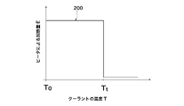
- the first reduction section 111 and the second reduction section 112 have the same heating amount E at the target temperature Tt. Therefore, as shown in FIG. 7 or 8, the profiles 200 and 201 in which the heating amount decreases at the target temperature Tt are excluded from the heating amount control profile 100.
- FIG. FIG. 7 is a simple on/off control
- FIG. 8 is a modified example of FIG.
- the heating amount E decreases sharply at the target temperature Tt, so the temperature fluctuations with respect to the target temperature increase. This is because the coolant is radiated by the heat radiator 7, and if the amount of heat is suddenly set to "zero" after the coolant has reached the target temperature Tt, the coolant temperature T drops rapidly from the target temperature.
- both the first decreasing portion 111 and the second decreasing portion 112 have a negative slope in the function, and the heating amount control profile at an arbitrary temperature in the second region 111B
- the slope of 100 (100A to 100E) is more negative than the slope of heating amount control profile 100 (100A to 100E) at an arbitrary temperature in first region 111A.
- the target temperature can be reached early, and the fluctuation of the temperature with respect to the target temperature can be reduced.
- a profile 203 with a smaller negative magnitude than the slope at the temperature of is excluded from the heating amount control profile 100 .
- the rate of temperature rise is slow and the target temperature cannot be reached early.
- FIGS. It includes a form having a constant portion 120 in which the heating amount E is constant even if it rises to the side.
- the second reducing portion 112 is adapted to the amount of heat dissipation that maintains the heating amount E at a predetermined heating amount on the higher temperature side than the target temperature Tt. It is preferred to have region 112A.
- the heat radiation amount corresponding area 112A is an area in which the heating amount E is brought close to zero but not zero. It is more preferable that Te at the end of the heat dissipation corresponding region 112A is ⁇ target temperature Tt+8°C ⁇ 1°C.
- the start time T2 of the heat dissipation corresponding area 112A is preferably ⁇ target temperature Tt+4° C. ⁇ 1° C., for example.
- the radiator 7 radiates heat, and if the amount of heat is suddenly set to "zero" even though the temperature has risen and exceeded the target temperature Tt, the coolant temperature T will fall below the target temperature, leading to temperature hunting. Temperature hunting can be suppressed by providing the heat quantity corresponding region 112A.
- the temperature T at which the heating amount E is 0 is preferably 90°C. If the temperature exceeds 90°C, problems such as unintended precipitation of components dissolved in the coolant or deterioration of heat conduction due to the generation of bubbles at the interface between the coolant and the heat transfer wire may occur.
- each heating amount control profile 100 (100A to 100E) will be described in more detail.
- FIG. 2 is a diagram showing a first example of a heating amount control profile.
- the decreasing portion 110 is a curve having an inflection point P, and the temperature T at the inflection point P coincides with the target temperature Tt. contain.
- the heating amount control profile 100 (100A) of the first example reaches the target temperature Tt within 15 minutes, for example, and controls the temperature with respect to the target temperature Tt within the range ⁇ target temperature Tt ⁇ 1° C., for example. can be done. Further, since the temperature T at which the point of inflection P coincides with the target temperature Tt, it is possible to control the fluctuation of the temperature with respect to the target temperature Tt to be smaller.
- FIG. 3 is a diagram showing a second example of the heating amount control profile.
- the decreasing portion 110 is a curve having an inflection point P, and the temperature T at the inflection point P is higher than the target temperature Tt. contain.
- the temperature T that becomes the inflection point P is preferably more than ⁇ target temperature Tt ⁇ +0°C and +4°C or less, and more preferably ⁇ target temperature Tt ⁇ +1°C or more and +2°C or less.
- the coolant may be heated too much with respect to the target temperature.
- the heating amount control profile 100 (100B) of the second example reaches the target temperature Tt within 15 minutes, for example, and controls the temperature with respect to the target temperature Tt within the range of ⁇ target temperature Tt ⁇ 1° C., for example. can be done.
- the temperature T that becomes the inflection point P is on the higher temperature side than the target temperature Tt, it becomes easy to set the heating amount E by the heater relatively large when the coolant temperature T is the target temperature Tt.
- the vehicle air conditioner 900 in which the radiator 7 radiates a relatively large amount of heat it is possible to suitably control the fluctuation of the temperature with respect to the target temperature Tt to be small.
- FIG. 4 is a diagram showing a third example of the heating amount control profile.
- the decreasing portion 110 is a curve having an inflection point P, and the temperature T at which the inflection point P is lower than the target temperature Tt.
- the second region 111B includes a configuration in a region on the lower temperature side than the inflection point P.
- the temperature T that becomes the inflection point P is preferably ⁇ target temperature Tt ⁇ -4°C or higher and lower than 0°C, and more preferably ⁇ target temperature Tt ⁇ -1°C or higher and -2°C or lower.
- the first decreasing portion 111 includes a third region 111C, which is a region higher than the temperature at which the inflection point P is reached.
- the heating amount control profile 100 (100C) of the third example reaches the target temperature Tt within 15 minutes, for example, and controls the temperature with respect to the target temperature Tt within the range of ⁇ target temperature Tt ⁇ 1° C., for example. can be done.
- the temperature T that becomes the inflection point P is on the lower temperature side than the target temperature Tt, it becomes easy to set the heating amount E by the heater relatively small when the coolant temperature T is the target temperature Tt.
- the vehicle air conditioner 900 in which the amount of heat released by the radiator 7 is relatively small it is possible to suitably control the fluctuation of the temperature with respect to the target temperature Tt to be small.
- FIG. 5 is a diagram showing a fourth example of the heating amount control profile.
- both the first region 111A and the second region 111B are linear functions with mutually different slopes.
- the heating amount control profile 100 (100D) of the fourth example reaches the target temperature Tt within 15 minutes, for example, and controls the temperature relative to the target temperature Tt within the range ⁇ target temperature Tt ⁇ 1° C. can be done.
- FIG. 6 is a diagram showing a fifth example of the heating amount control profile.
- the decreasing portion 110 includes a form that is a curve having no inflection point.
- the heating amount control profile 100 (100E) of the fifth example reaches the target temperature Tt within 15 minutes, for example, and controls the temperature with respect to the target temperature Tt within the range ⁇ target temperature Tt ⁇ 1° C. can be done.
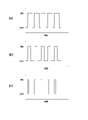
- FIG. 11 is a diagram showing an example of duty control of the heating cycle device, in which (a) is duty control in a constant portion, (b) is duty control at an arbitrary temperature in a decreasing portion, and (c) is a heat release corresponding region. shows the duty control at any temperature of The duty ratio in the decreasing portion 110 (shown in FIGS. 2-6) is made smaller than the duty ratio in the constant portion 120 (shown in FIGS. 2-6).
- the reducing unit 110 gradually decreases the duty ratio with the lapse of time, thereby adjusting the heating amount E by the heater 4 as shown in FIGS. 2 to 6.
- FIG. Alternatively, the reducing section 110 gradually reduces the duty ratio as the temperature of the coolant rises, thereby adjusting the heating amount E by the heater 4 as shown in FIGS.
- the cycle of duty control is not particularly limited, but is preferably 0.015 to 0.025 seconds, for example.
- the period of duty control is set to 0.02 seconds as an example.
- the duty ratio in the constant portion 120 is not particularly limited, it is preferably 60% or more and 100% or less.
- the duty ratio in the constant section 120 is set to 80%.
- the duty ratio of the reducing section 110 (shown in FIGS. 2 to 6) at any temperature is not particularly limited, but is preferably 30% or more and less than 60%.
- the duty ratio at the target temperature Tt shown in FIG.
- the duty ratio at any temperature in the heat dissipation amount corresponding region is not particularly limited, it is preferably more than 0% and less than 30%. In FIG. 11(c), as an example, the duty ratio at an arbitrary temperature in the heat dissipation corresponding region is 20%.
- the heating amount at the inflection point P is preferably 70% or less, more preferably 60% or less, of the heating amount at the constant portion 120. .
- the amount of heating at the inflection point P exceeds 70% of the amount of heating at the constant portion 120, the temperature of the coolant is increased, and even after the target temperature Tt is exceeded, the heating is continued more than necessary, and the temperature T of the coolant is decreased. It becomes difficult to control so as to approximate the target temperature Tt.
- the lower limit of the amount of heating at the inflection point P is not particularly limited, it is preferably 30% or more, more preferably 40% or more, of the amount of heating at the constant portion 120 .
- the heating amount at the inflection point P is less than 30% of the heating amount of the constant portion 120, the heating amount becomes insufficient when the coolant temperature approaches the target temperature Tt, and the time required for the coolant temperature to reach the target temperature Tt is reduced. It can be long.
- a vehicle air conditioner 900 includes the heating cycle device 1 according to the present embodiment and is mounted on a vehicle.
- the vehicle air conditioner 900 has a temperature control unit 901 that adjusts the temperature of the air supplied to the vehicle interior, and the radiator 7 is a hot water type heat exchanger arranged inside the temperature control unit 901. It is a vessel.
- a vehicle air conditioner 900 has a blower unit 904 and a temperature control unit 901 .
- the blower unit 904 is provided with a blower 902 that blows air taken in from an inside air inlet and/or an outside air inlet (not shown) toward an air flow path 903 .
- the internal space of the temperature control unit 901 is an air flow path 903, and the hot water type heat exchanger (radiator) 7 is arranged in the air flow path 903.
- the hot water type heat exchanger (radiator) 7 is arranged in the air flow path 903.
- An air mix door (not shown) that is arranged between the device and the hot water heat exchanger 7 and adjusts the ratio of the air that passes through the hot water heat exchanger 7 and the air that bypasses the hot water heat exchanger 7 It is preferable to further have A defrost opening (not shown), a vent opening (not shown), and a foot opening (not shown) are provided at the most downstream portion of the temperature control unit 901 . Each opening is indirectly or directly connected to an air outlet (not shown) in the passenger compartment via a duct (not shown).
- Vehicles include, for example, an electric vehicle (EV) that runs only on an electric motor, a hybrid vehicle (HEV) that runs on a plurality of power sources including an electric motor and an internal combustion engine, or an internal combustion engine that only generates power and uses that power.
- EV electric vehicle
- HEV hybrid vehicle
- HEV hybrid vehicle
- the total amount of coolant in the coolant loop tends to be smaller than that of the engine-equipped vehicle, and if temperature hunting occurs at the outflow point of the fluid heating unit, the entire path is likely to be affected by hunting.
- the heating cycle device 1 installed in such a vehicle air conditioner can control temperature hunting to be small.
- the temperature of the hot air blown out from the air outlet in the passenger compartment may hunt and comfort may be impaired.
- the vehicle air conditioner 900 is operated in the temperature conditioning mode, it is necessary to frequently adjust the position of the air mix door in order to stabilize the temperature of the blown hot air. There is a risk that comfort will be impaired due to the operating noise emitted by the actuators.
- the air volume of the blower 902, the temperature of the air upstream of the radiator 7, and the temperature of the conditioned air downstream of the air mix door are detected and input to the heating control device 6, and the amount of heat released by the radiator 7 is detected. It is preferable to estimate and change the heating amount at the inflection point P in FIGS. Specifically, when the amount of heat released by the radiator 7 is relatively large, the inflection point P is adjusted to a value that provides a larger amount of heating, and when the amount of heat released by the radiator 7 is relatively small, the inflection point Adjust P to a less heated value.
- the heat release amount 7 is large, the coolant temperature T can reach the target temperature Tt early.
- the temperature T of the coolant is reliably prevented from further increasing after reaching the target temperature Tt, and the temperature T of the coolant is controlled to approximate the target temperature Tt. can do.
- Example 1 The heating control device controlled the switching operation of the transistor based on the heating amount control profile shown in FIG. 2, and adjusted the heating amount by the heater by changing the on-off duty ratio of the transistor.
- the target temperature was set at 80°C. 12 is a diagram showing the relationship between the heating time and the coolant temperature in Example 1.
- FIG. 12 the area denoted by reference numeral 301 corresponds to the constant portion 120 in FIG. Equivalent to.
- Example 1 The amount of heating by the heater was adjusted in the same manner as in Example 1, except that the heating amount control profile was changed to the profile shown in FIG.
- the target temperature was set at 80°C. 13 is a diagram showing the relationship between the heating time and the coolant temperature in Comparative Example 1.
- Example 2 The heating amount by the heater was adjusted in the same manner as in Example 1, except that the heating amount profile was changed to the profile shown in FIG.
- the target temperature was set at 80°C.
- 14 is a diagram showing the relationship between the heating time and the coolant temperature in Comparative Example 2.
- Example 1 as shown in FIG. 12, the time to reach the target temperature was within 15 minutes, and the target temperature could be reached in a short time. Furthermore, the fluctuation of the temperature with respect to the target temperature was within the range of ⁇ 1° C. of the target temperature, and the fluctuation of the temperature could be controlled to be small. On the other hand, in Comparative Example 1, as shown in FIG. 13, the time to reach the target temperature was within 15 minutes, but the temperature fluctuation with respect to the target temperature was ⁇ 5 ° C. was big. In Comparative Example 2, as shown in FIG. 14, the fluctuation of the temperature with respect to the target temperature was within the range of ⁇ 1° C. of the target temperature, but the time to reach the target temperature exceeded 20 minutes. was long.
- Heating cycle device Circulation flow path 3 Pump 4 Heater 5 Transistor 6 Heating control device 7 Radiator 8 Battery 10 Fluid heating unit 10a Outlet 10b Inlet 11, 12, 13 Piping 50 Temperature sensor 100 (100A to 100E) Amount of heating Control profile 110 Reduction section 111 First reduction section 112 Second reduction section 111A First region 111B Second region 111C Third region 112A Heat dissipation corresponding regions 200, 201, 202, 203 Profile 900 Vehicle air conditioner 901 Temperature control unit 902 Blower 903 Air flow path 904 Blower unit P Inflection point
Landscapes
- Physics & Mathematics (AREA)
- Thermal Sciences (AREA)
- Engineering & Computer Science (AREA)
- Mechanical Engineering (AREA)
- Air-Conditioning For Vehicles (AREA)
Abstract
Priority Applications (3)
| Application Number | Priority Date | Filing Date | Title |
|---|---|---|---|
| CN202280031029.9A CN117203072A (zh) | 2021-04-28 | 2022-04-21 | 制热控制装置以及控制程序、流体加热单元、制热循环装置以及具备制热循环装置的车辆用空调装置 |
| EP22795671.1A EP4331878A1 (fr) | 2021-04-28 | 2022-04-21 | Dispositif de régulation de chauffage et programme de régulation, unité de chauffage de fluide, dispositif à cycle de chauffage et climatiseur de véhicule qui en est équipé |
| JP2023517480A JPWO2022230758A1 (fr) | 2021-04-28 | 2022-04-21 |
Applications Claiming Priority (2)
| Application Number | Priority Date | Filing Date | Title |
|---|---|---|---|
| JP2021075966 | 2021-04-28 | ||
| JP2021-075966 | 2021-04-28 |
Publications (1)
| Publication Number | Publication Date |
|---|---|
| WO2022230758A1 true WO2022230758A1 (fr) | 2022-11-03 |
Family
ID=83846877
Family Applications (1)
| Application Number | Title | Priority Date | Filing Date |
|---|---|---|---|
| PCT/JP2022/018481 WO2022230758A1 (fr) | 2021-04-28 | 2022-04-21 | Dispositif de régulation de chauffage et programme de régulation, unité de chauffage de fluide, dispositif à cycle de chauffage et climatiseur de véhicule qui en est équipé |
Country Status (4)
| Country | Link |
|---|---|
| EP (1) | EP4331878A1 (fr) |
| JP (1) | JPWO2022230758A1 (fr) |
| CN (1) | CN117203072A (fr) |
| WO (1) | WO2022230758A1 (fr) |
Citations (4)
| Publication number | Priority date | Publication date | Assignee | Title |
|---|---|---|---|---|
| JP2003335127A (ja) | 2002-05-22 | 2003-11-25 | Denso Corp | 車両用電気機器制御装置 |
| JP2015058741A (ja) * | 2013-09-17 | 2015-03-30 | マツダ株式会社 | 車両用空調制御装置 |
| JP2017215084A (ja) | 2016-05-31 | 2017-12-07 | カルソニックカンセイ株式会社 | 流体加熱装置 |
| JP2018114945A (ja) * | 2017-01-20 | 2018-07-26 | サンデン・オートモーティブクライメイトシステム株式会社 | 車両用空気調和装置 |
-
2022
- 2022-04-21 CN CN202280031029.9A patent/CN117203072A/zh active Pending
- 2022-04-21 JP JP2023517480A patent/JPWO2022230758A1/ja active Pending
- 2022-04-21 WO PCT/JP2022/018481 patent/WO2022230758A1/fr active Application Filing
- 2022-04-21 EP EP22795671.1A patent/EP4331878A1/fr active Pending
Patent Citations (4)
| Publication number | Priority date | Publication date | Assignee | Title |
|---|---|---|---|---|
| JP2003335127A (ja) | 2002-05-22 | 2003-11-25 | Denso Corp | 車両用電気機器制御装置 |
| JP2015058741A (ja) * | 2013-09-17 | 2015-03-30 | マツダ株式会社 | 車両用空調制御装置 |
| JP2017215084A (ja) | 2016-05-31 | 2017-12-07 | カルソニックカンセイ株式会社 | 流体加熱装置 |
| JP2018114945A (ja) * | 2017-01-20 | 2018-07-26 | サンデン・オートモーティブクライメイトシステム株式会社 | 車両用空気調和装置 |
Also Published As
| Publication number | Publication date |
|---|---|
| EP4331878A1 (fr) | 2024-03-06 |
| CN117203072A (zh) | 2023-12-08 |
| JPWO2022230758A1 (fr) | 2022-11-03 |
Similar Documents
| Publication | Publication Date | Title |
|---|---|---|
| US20190273294A1 (en) | Traction battery cooling system with coolant proportional valve | |
| US8740104B2 (en) | Variable electric auxiliary heater circuit pump | |
| US10293658B2 (en) | Traction battery cooling system for an electrified vehicle | |
| US8859938B2 (en) | Vehicle cabin heating system | |
| KR101566735B1 (ko) | 하이브리드 차량의 실내 난방 방법 및 장치 | |
| JP3199025B2 (ja) | 車両用エンジン冷却および暖房装置 | |
| CN101837778B (zh) | 辅助加热器泵控制 | |
| CA2911557C (fr) | Dispositif de commande d'un systeme de conditionnement de l'air | |
| US6713729B2 (en) | Electric load control system and vehicle air-conditioning system having the same | |
| CN108698477B (zh) | 车用空调装置 | |
| JP2004060653A (ja) | 車両の冷却加熱循環系を作動する方法 | |
| CN111347833A (zh) | 电动车的温度调节控制系统 | |
| JP7115452B2 (ja) | 冷却システム | |
| JP2003127634A (ja) | 車両用空調装置 | |
| CN110395107B (zh) | 车辆驱动系统的冷却装置 | |
| JP2004360509A (ja) | 内燃機関の冷却装置 | |
| JP7024631B2 (ja) | 車両の暖房装置 | |
| WO2022230758A1 (fr) | Dispositif de régulation de chauffage et programme de régulation, unité de chauffage de fluide, dispositif à cycle de chauffage et climatiseur de véhicule qui en est équipé | |
| JP2003002039A (ja) | 車両用空調装置および車両用電気負荷制御装置 | |
| WO2017159496A1 (fr) | Dispositif de chauffage de liquide | |
| WO2023026871A1 (fr) | Dispositif de régulation de chauffage et programme de régulation, unité de chauffage de fluide, dispositif à cycle de chauffage et climatiseur de véhicule le comprenant | |
| JP6221920B2 (ja) | 車両用空調装置 | |
| WO2023153342A1 (fr) | Dispositif de régulation de chauffage et programme de régulation, unité de chauffage de fluide, dispositif à cycle de chauffage et dispositif de climatisation de véhicule le comprenant | |
| KR101475793B1 (ko) | 전기자동차용 공조장치 | |
| KR20170002214A (ko) | 하이브리드 차량의 실내 난방 방법 |
Legal Events
| Date | Code | Title | Description |
|---|---|---|---|
| 121 | Ep: the epo has been informed by wipo that ep was designated in this application |
Ref document number: 22795671 Country of ref document: EP Kind code of ref document: A1 |
|
| ENP | Entry into the national phase |
Ref document number: 2023517480 Country of ref document: JP Kind code of ref document: A |
|
| WWE | Wipo information: entry into national phase |
Ref document number: 202280031029.9 Country of ref document: CN |
|
| WWE | Wipo information: entry into national phase |
Ref document number: 18288703 Country of ref document: US |
|
| WWE | Wipo information: entry into national phase |
Ref document number: 2022795671 Country of ref document: EP |
|
| NENP | Non-entry into the national phase |
Ref country code: DE |
|
| ENP | Entry into the national phase |
Ref document number: 2022795671 Country of ref document: EP Effective date: 20231128 |