WO2022230576A1 - 電池管理装置、電力システム - Google Patents
電池管理装置、電力システム Download PDFInfo
- Publication number
- WO2022230576A1 WO2022230576A1 PCT/JP2022/015907 JP2022015907W WO2022230576A1 WO 2022230576 A1 WO2022230576 A1 WO 2022230576A1 JP 2022015907 W JP2022015907 W JP 2022015907W WO 2022230576 A1 WO2022230576 A1 WO 2022230576A1
- Authority
- WO
- WIPO (PCT)
- Prior art keywords
- battery
- period
- management device
- battery management
- difference
- Prior art date
Links
- 238000007599 discharging Methods 0.000 claims abstract description 13
- 238000004364 calculation method Methods 0.000 claims description 19
- 238000001514 detection method Methods 0.000 claims description 18
- 230000008859 change Effects 0.000 claims description 9
- 238000012545 processing Methods 0.000 claims description 2
- 238000005516 engineering process Methods 0.000 abstract description 3
- 238000000034 method Methods 0.000 description 23
- 230000007547 defect Effects 0.000 description 12
- 230000006870 function Effects 0.000 description 10
- 238000010586 diagram Methods 0.000 description 9
- 238000004891 communication Methods 0.000 description 5
- 238000002847 impedance measurement Methods 0.000 description 5
- 230000002950 deficient Effects 0.000 description 4
- 238000005259 measurement Methods 0.000 description 4
- 230000008569 process Effects 0.000 description 4
- 208000032953 Device battery issue Diseases 0.000 description 3
- 238000012986 modification Methods 0.000 description 3
- 230000004048 modification Effects 0.000 description 3
- 230000002159 abnormal effect Effects 0.000 description 1
- 230000008901 benefit Effects 0.000 description 1
- 238000002474 experimental method Methods 0.000 description 1
- 238000012886 linear function Methods 0.000 description 1
- 230000007257 malfunction Effects 0.000 description 1
- 238000005457 optimization Methods 0.000 description 1
- 238000011160 research Methods 0.000 description 1
- 230000000284 resting effect Effects 0.000 description 1
- 239000013589 supplement Substances 0.000 description 1
- 230000002123 temporal effect Effects 0.000 description 1
Images


Classifications
-
- G—PHYSICS
- G01—MEASURING; TESTING
- G01R—MEASURING ELECTRIC VARIABLES; MEASURING MAGNETIC VARIABLES
- G01R31/00—Arrangements for testing electric properties; Arrangements for locating electric faults; Arrangements for electrical testing characterised by what is being tested not provided for elsewhere
- G01R31/36—Arrangements for testing, measuring or monitoring the electrical condition of accumulators or electric batteries, e.g. capacity or state of charge [SoC]
- G01R31/382—Arrangements for monitoring battery or accumulator variables, e.g. SoC
- G01R31/3835—Arrangements for monitoring battery or accumulator variables, e.g. SoC involving only voltage measurements
-
- G—PHYSICS
- G01—MEASURING; TESTING
- G01R—MEASURING ELECTRIC VARIABLES; MEASURING MAGNETIC VARIABLES
- G01R31/00—Arrangements for testing electric properties; Arrangements for locating electric faults; Arrangements for electrical testing characterised by what is being tested not provided for elsewhere
- G01R31/36—Arrangements for testing, measuring or monitoring the electrical condition of accumulators or electric batteries, e.g. capacity or state of charge [SoC]
- G01R31/392—Determining battery ageing or deterioration, e.g. state of health
-
- H—ELECTRICITY
- H01—ELECTRIC ELEMENTS
- H01M—PROCESSES OR MEANS, e.g. BATTERIES, FOR THE DIRECT CONVERSION OF CHEMICAL ENERGY INTO ELECTRICAL ENERGY
- H01M10/00—Secondary cells; Manufacture thereof
- H01M10/42—Methods or arrangements for servicing or maintenance of secondary cells or secondary half-cells
- H01M10/425—Structural combination with electronic components, e.g. electronic circuits integrated to the outside of the casing
-
- H—ELECTRICITY
- H01—ELECTRIC ELEMENTS
- H01M—PROCESSES OR MEANS, e.g. BATTERIES, FOR THE DIRECT CONVERSION OF CHEMICAL ENERGY INTO ELECTRICAL ENERGY
- H01M10/00—Secondary cells; Manufacture thereof
- H01M10/42—Methods or arrangements for servicing or maintenance of secondary cells or secondary half-cells
- H01M10/48—Accumulators combined with arrangements for measuring, testing or indicating the condition of cells, e.g. the level or density of the electrolyte
-
- H—ELECTRICITY
- H02—GENERATION; CONVERSION OR DISTRIBUTION OF ELECTRIC POWER
- H02J—CIRCUIT ARRANGEMENTS OR SYSTEMS FOR SUPPLYING OR DISTRIBUTING ELECTRIC POWER; SYSTEMS FOR STORING ELECTRIC ENERGY
- H02J7/00—Circuit arrangements for charging or depolarising batteries or for supplying loads from batteries
- H02J7/0047—Circuit arrangements for charging or depolarising batteries or for supplying loads from batteries with monitoring or indicating devices or circuits
- H02J7/0048—Detection of remaining charge capacity or state of charge [SOC]
-
- H—ELECTRICITY
- H02—GENERATION; CONVERSION OR DISTRIBUTION OF ELECTRIC POWER
- H02J—CIRCUIT ARRANGEMENTS OR SYSTEMS FOR SUPPLYING OR DISTRIBUTING ELECTRIC POWER; SYSTEMS FOR STORING ELECTRIC ENERGY
- H02J7/00—Circuit arrangements for charging or depolarising batteries or for supplying loads from batteries
- H02J7/0047—Circuit arrangements for charging or depolarising batteries or for supplying loads from batteries with monitoring or indicating devices or circuits
- H02J7/005—Detection of state of health [SOH]
-
- H—ELECTRICITY
- H01—ELECTRIC ELEMENTS
- H01M—PROCESSES OR MEANS, e.g. BATTERIES, FOR THE DIRECT CONVERSION OF CHEMICAL ENERGY INTO ELECTRICAL ENERGY
- H01M10/00—Secondary cells; Manufacture thereof
- H01M10/42—Methods or arrangements for servicing or maintenance of secondary cells or secondary half-cells
- H01M10/425—Structural combination with electronic components, e.g. electronic circuits integrated to the outside of the casing
- H01M2010/4271—Battery management systems including electronic circuits, e.g. control of current or voltage to keep battery in healthy state, cell balancing
-
- Y—GENERAL TAGGING OF NEW TECHNOLOGICAL DEVELOPMENTS; GENERAL TAGGING OF CROSS-SECTIONAL TECHNOLOGIES SPANNING OVER SEVERAL SECTIONS OF THE IPC; TECHNICAL SUBJECTS COVERED BY FORMER USPC CROSS-REFERENCE ART COLLECTIONS [XRACs] AND DIGESTS
- Y02—TECHNOLOGIES OR APPLICATIONS FOR MITIGATION OR ADAPTATION AGAINST CLIMATE CHANGE
- Y02E—REDUCTION OF GREENHOUSE GAS [GHG] EMISSIONS, RELATED TO ENERGY GENERATION, TRANSMISSION OR DISTRIBUTION
- Y02E60/00—Enabling technologies; Technologies with a potential or indirect contribution to GHG emissions mitigation
- Y02E60/10—Energy storage using batteries
Definitions
- the present invention relates to technology for managing the state of batteries.
- ⁇ A battery state estimating device (100) comprises an acquisition means (110) for acquiring the complex impedance of a battery at a plurality of different temperatures, and a complex plane whose axes are the real and imaginary components of the complex impedance.
- the calculation means (120) for calculating the slope of the straight line connecting the values of the plurality of acquired complex impedances at the first predetermined frequency as the slope of the complex impedance, the slope of the complex impedance, and the battery related to the battery Storage means (130) for pre-storing the relationship with the state, and estimating means (140) for estimating the battery state based on the calculated slope of the complex impedance and the stored relationship.
- the present invention has been made in view of the above-described problems, and is a technology that enables estimation of the battery state along with charging and discharging operations of the battery without using dedicated equipment for estimating the state of the battery. intended to provide
- a battery management device specifies a first period and a second period after a rest period after a battery finishes discharging or charging, and uses the difference in output voltage in the second period to Estimate the state of
- the battery state can be estimated along with the charge/discharge operation of the battery without using dedicated equipment for estimating the battery state.
- FIG. 4 is a graph showing changes over time in the output voltage of a battery during a rest period after the battery has finished discharging.
- FIG. 10 is an example of relationship data describing the relationship between ⁇ Vb and ⁇ Va_lim;
- FIG. It is a figure which shows the modification of relational data.
- 4 is a flowchart for explaining a procedure for estimating whether or not there is a problem with a battery;
- 4 is a graph comparing variation in output voltage over time between a normal battery and a defective battery during a rest period after a discharge operation.
- FIG. 10 is an example of relationship data describing the relationship between ⁇ Vb and ⁇ Va_lim
- FIG. It is a figure which shows the modification of relational data.
- 4 is a flowchart for explaining a procedure for estimating whether or not there is a problem with a battery;
- 4 is a graph comparing variation in output voltage over time between a normal battery and a defective battery during a rest period after a discharge
- FIG. 10 is a schematic diagram showing a state of estimating the presence or absence of a defect using ⁇ _lim; 10 is a flowchart for explaining a procedure for estimating the presence/absence of a battery failure in Embodiment 3.
- FIG. FIG. 12 is a schematic diagram illustrating an application of the battery management device according to Embodiment 4;
- FIG. 13 is a diagram showing a configuration example of a battery management device 100 according to Embodiment 4; 4 is a diagram showing another configuration example of the battery management device 100.
- FIG. A configuration example in which the detection unit 130 is connected to the battery 200 is shown. It is an example of a user interface presented by the battery management device 100 .
- FIG. 1 is a graph showing changes over time in battery output voltage during a rest period after the battery has finished discharging.
- the output voltage sharply increases and then gently increases.
- a period during which the output voltage sharply increases is called a first period
- a subsequent period during which the output voltage gradually increases is called a second period.
- the time length of the first period is ⁇ t
- the difference in output voltage from the start point to the end point of the first period is ⁇ Va.
- the difference in output voltage from the start point to the end point of the second period is ⁇ Vb.
- ⁇ Va_lim is a linear function (typically proportional) of ⁇ Vb.
- ⁇ Va_lim is a linear function (typically proportional) of ⁇ Vb.
- FIG. 2 is an example of relationship data describing the relationship between ⁇ Vb and ⁇ Va_lim.
- ⁇ Vb and ⁇ Va_lim are typically proportional. That is, the larger ⁇ Vb is, the larger the normal range of ⁇ Va is. If ⁇ Va is greater than or equal to this normal range (that is, ⁇ Va ⁇ Va_lim), it is estimated that the battery is malfunctioning. Referring to FIG. 2, when actually measured values of ⁇ Va and ⁇ Vb are plotted, if ⁇ Va is larger than the solid line in FIG. 2, ⁇ Va is abnormal.
- FIG. 2 shows an example in which the relationship between the two is described for each value of ⁇ t. Further, similar relationship data may be provided for each type of battery cell. The relationship between these values can be obtained in advance through experiments, for example.
- ⁇ Va_lim can be defined according to the respective values of ⁇ t and ⁇ Vb, so the timing at which these values are actually measured can be determined somewhat freely. However, there is no change in the fact that these values should be measured during the period when the battery failure is well manifested. For example, it is not desirable to actually measure both ⁇ Va and ⁇ Vb during the period immediately after the start of the idle period when the output voltage is rapidly increasing. Similarly, it is not desirable to measure both of these during a period in which the change over time of the output voltage is stable during the pause period. Therefore, although the timing of ⁇ t and ⁇ Vb is somewhat arbitrary, they should be obtained at the timing when the output voltage rapidly increases as shown in FIG. 1 and then increases slightly gradually. Since these depend on the characteristics of the battery, appropriate timings may be defined for each battery type.
- the first period and the second period may partially overlap. That is, if the second period ends after the end time of the first period, it can be used as the second period.
- the start time of the first period may be after the end time of the rest period. That is, it is sufficient that both the entire first period and the entire second period are included in the pause period. However, the end time of the second period is after the end time of the first period.
- FIG. 3 is a diagram showing a modified example of relational data.
- the function representing the relationship between ⁇ Vb and ⁇ Va_lim may vary depending on at least one of battery temperature T, battery discharge current I, and battery end-of-discharge voltage V.
- FIG. In that case, function parameters are defined in advance for each value of T, each value of I, and each value of V, and ⁇ Va_lim is calculated using the function parameters corresponding to these measured values. Therefore, the function f representing the relationship between ⁇ Vb and ⁇ Va_lim in this case is defined as follows.
- ⁇ Va_lim f( ⁇ Vb, c_Rn_T_1, c_Rn_T_2, ..., c_Rn_I_1, c_Rn_I_2, ..., c_Rn_V_1, c_Rn_V_2, ... )
- function f Since ⁇ Va_lim is a function of ⁇ Vb, function f has ⁇ Vb as an argument.
- the function f further includes one or more parameters c_Rn_T that vary according to the temperature T.
- one or more parameters c_Rn_I that change according to the current I and c_Rn_V that change according to the voltage V are included.
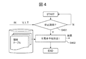
- FIG. 4 is a flowchart explaining the procedure for estimating whether there is a problem with the battery. Each step in FIG. 4 will be described below.
- Fig. 4 Step S401: Supplement
- function parameters are defined for each value of T, each value of I, and each value of V, as described with reference to FIG. 3, these values may be acquired in this step (or a step to be described later). These values can be obtained, for example, from a management unit arranged for each battery cell.
- Embodiment 1 Summary>
- the ratio of the voltage difference ⁇ Va in the first period to the voltage difference ⁇ Vb in the second period is calculated, and if the ratio is equal to or greater than the threshold value ⁇ Va_lim, it is estimated that the battery has a problem. As a result, it is possible to estimate whether the battery is in a normal state without preparing equipment used for, for example, impedance measurement.
- Embodiment 1 the relationship between ⁇ Va_lim and ⁇ Vb can be defined for each value of ⁇ t. As a result, the measured values of ⁇ Va and ⁇ Vb can be obtained at relatively free timing.
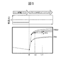
- FIG. 5 is a graph comparing variations in output voltage over time between a normal battery and a defective battery during a pause period after discharging operation.
- a normal battery during the third period (time tc0 to time tc1 in FIG. 5) in which the change over time of the output voltage is stable, no matter how many times the difference ⁇ Vc in the output voltage is measured, the value is approximately the same.
- the present inventor's research has revealed that the value of ⁇ Vc in a battery with a problem greatly varies each time it is measured. Therefore, in a second embodiment of the present invention, a procedure for estimating whether or not there is a problem with the battery according to the variation in ⁇ Vc will be described.
- the third period it is desirable to set the third period to a timing when the output voltage of the battery with the problem varies greatly for each measurement.
- a period within one second after the start of the idle period and following the second period described in the first embodiment may be used as the third period.
- the end time of the second period and the start time of the third period may not necessarily be the same, for example, the second period and the third period may partially overlap, or the end time of the second period and the start of the third period
- An interval may be provided between the time.
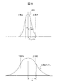
- FIG. 6 is a schematic diagram showing how ⁇ _lim is used to estimate the presence or absence of a defect. If the variation of ⁇ Vc (standard deviation ⁇ ) is within three times the standard deviation ⁇ _new of a new battery, it can be said that the variation is generally within the normal range. On the other hand, if ⁇ varies beyond the range of ⁇ 3 ⁇ _new, it can be estimated that the battery is defective.
- FIG. 7 is a flowchart for explaining the procedure for estimating the presence or absence of a battery failure in Embodiment 3 of the present invention.
- the normality of the battery can be estimated.
- the normality of the battery can be estimated as follows. These rankings are an example, and other rankings are also possible.
- Embodiment 4 of the present invention a configuration example of a battery management apparatus that implements the method of estimating the presence or absence of a problem in the battery described in Embodiments 1 to 3 will be described.
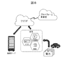
- FIG. 8 is a schematic diagram illustrating the application of the battery management device according to the fourth embodiment.
- the battery management device estimates whether there is a problem with the battery according to the procedures of the flowcharts described in the first to third embodiments.
- Batteries eg, battery cells, battery modules, battery packs, etc.
- the battery is either in charging/discharging/resting state when connected to these devices.
- the presence or absence of defects can be calculated, for example, on the device described above, or on a computer connected via a network, such as on a cloud server.
- the advantage of computing on the device to which the battery is connected is that the battery status (voltage output by the battery, current output by the battery, temperature of the battery, etc.) can be obtained frequently.
- the presence or absence of defects calculated on the cloud system can also be sent to the computer owned by the user.
- the user computer can provide this data for specific uses, such as inventory management.
- the presence or absence of defects calculated on the cloud system can be stored in the database of the cloud platform operator and used for other purposes. For example, optimization of replacement routes for electric vehicles, energy management, and so on.
- FIG. 9 is a diagram showing a configuration example of the battery management device 100 according to the fourth embodiment.
- a battery management device 100 is a device that is connected to a battery 200 and receives power from the battery 200, and corresponds to the tester or the like in FIG.
- the battery management device 100 includes a communication section 110 , a calculation section 120 , a detection section 130 and a storage section 140 .
- the detection unit 130 acquires the detected value V of the voltage output by the battery 200 and the detected value I of the current output by the battery 200 . Furthermore, as an option, the detected value T of the temperature of the battery 200 may be acquired. These detection values may be detected by battery 200 itself and notified to detection unit 130 , or may be detected by detection unit 130 . Details of the detection unit 130 will be described later.
- the calculation unit 120 uses the detection value acquired by the detection unit 130 to estimate whether the battery 200 is defective.
- the estimation procedure is the one described in the first to third embodiments.
- the communication unit 110 transmits the presence/absence of failure estimated by the calculation unit 120 to the outside of the battery management device 100 . For example, they can be transmitted to a memory provided by the cloud system.
- the storage unit 140 stores the relationship data described in the first to third embodiments.
- the arithmetic unit 120 can be configured by hardware such as a circuit device that implements the function, or by executing software that implements the function by an arithmetic unit such as a CPU (Central Processing Unit). can.
- hardware such as a circuit device that implements the function
- software that implements the function by an arithmetic unit such as a CPU (Central Processing Unit). can.
- CPU Central Processing Unit
- FIG. 10 is a diagram showing another configuration example of the battery management device 100.
- the battery management device 100 does not necessarily have to be directly connected to the battery 200 to receive power supply, and shows a configuration in which the communication unit 110 and the detection unit 130 shown in FIG. 9 are not included.
- battery management device 100 acquires voltage V, current I, and temperature T of battery 200 from communication unit 110 .
- the detection unit 150 included in the battery management device 100 receives these detection values via, for example, a network, and the calculation unit 120 uses these detection values to calculate the presence or absence of failure.
- FIG. 11 shows a configuration example when the detection unit 130 is connected to the battery 200.
- the detection unit 130 may be configured as part of the battery management device 100 or may be configured as a module separate from the battery management device 100 .
- the detection unit 130 includes a voltage sensor 131, a temperature sensor 132, and a current sensor 133 in order to obtain the voltage V, temperature T, and current I when the battery 200 is charged and discharged.
- the voltage sensor 131 measures the voltage across the battery 200 (the voltage output by the battery 200).
- the temperature sensor 132 is connected to, for example, a thermocouple included in the battery 200 and measures the temperature of the battery 200 via this.
- Current sensor 133 is connected to one end of battery 200 and measures the current output by battery 200 .
- Temperature sensor 132 is optional and need not be provided.
- FIG. 12 is an example of a user interface presented by the battery management device 100.
- FIG. A user interface can be presented on a display device, such as a display device.
- the user interface presents the calculation result by the calculation unit 120 .
- FIG. 12 shows changes over time in the output voltage during the rest period, as well as the results of estimating whether or not the battery has a problem.
- the present invention is not limited to the embodiments described above, and includes various modifications.
- the above-described embodiments have been described in detail in order to explain the present invention in an easy-to-understand manner, and are not necessarily limited to those having all the described configurations.
- part of the configuration of one embodiment can be replaced with the configuration of another embodiment, and the configuration of another embodiment can be added to the configuration of one embodiment.
- the relationship data may be stored in the storage unit 140 from the beginning, or may be acquired from a device other than the battery management device 100 when executing the flowcharts in each embodiment.
- the temporal change in the output voltage of a battery that has not deteriorated may be obtained from a device other than the battery management device 100, or may be actually measured by the battery management device 100 itself.
- the presence or absence of a defect is estimated during the rest period after the discharge operation of the storage battery.
- the presence/absence of a defect can be estimated in the same manner as in the above embodiments. It depends on the characteristics of the battery whether the voltage change corresponding to the presence/absence of the failure appears in the rest period after the discharge operation, the rest period after the charge operation, or both. Therefore, it is sufficient to estimate the presence/absence of failure in any one of these according to the characteristics of the battery.
- the battery management device 100 and the batteries 200 can also be configured as a power grid system composed of a plurality of batteries 200 .
- the battery management device 100 may control the operation of the battery 200 while estimating whether there is a problem with the battery, or the control of the battery 200 may be performed by another device.
- Battery management device 110 Communication unit 120: Calculation unit 130: Detection unit 140: Storage unit 200: Battery
Landscapes
- Engineering & Computer Science (AREA)
- Power Engineering (AREA)
- General Physics & Mathematics (AREA)
- Physics & Mathematics (AREA)
- Chemical Kinetics & Catalysis (AREA)
- Electrochemistry (AREA)
- General Chemical & Material Sciences (AREA)
- Manufacturing & Machinery (AREA)
- Chemical & Material Sciences (AREA)
- Microelectronics & Electronic Packaging (AREA)
- Medical Informatics (AREA)
- General Health & Medical Sciences (AREA)
- Health & Medical Sciences (AREA)
- Charge And Discharge Circuits For Batteries Or The Like (AREA)
- Secondary Cells (AREA)
- Tests Of Electric Status Of Batteries (AREA)
- Supply And Distribution Of Alternating Current (AREA)
Priority Applications (4)
| Application Number | Priority Date | Filing Date | Title |
|---|---|---|---|
| AU2022266288A AU2022266288B2 (en) | 2021-04-28 | 2022-03-30 | Battery management device, and electric power system |
| CN202280026150.2A CN117136313A (zh) | 2021-04-28 | 2022-03-30 | 电池管理装置、电力系统 |
| EP22795492.2A EP4333243A4 (en) | 2021-04-28 | 2022-03-30 | Battery management device, and electric power system |
| US18/287,485 US20240125860A1 (en) | 2021-04-28 | 2022-03-30 | Battery Management Device, and Electric Power System |
Applications Claiming Priority (2)
| Application Number | Priority Date | Filing Date | Title |
|---|---|---|---|
| JP2021075636A JP7583503B2 (ja) | 2021-04-28 | 2021-04-28 | 電池管理装置、電力システム |
| JP2021-075636 | 2021-04-28 |
Publications (1)
| Publication Number | Publication Date |
|---|---|
| WO2022230576A1 true WO2022230576A1 (ja) | 2022-11-03 |
Family
ID=83847403
Family Applications (1)
| Application Number | Title | Priority Date | Filing Date |
|---|---|---|---|
| PCT/JP2022/015907 WO2022230576A1 (ja) | 2021-04-28 | 2022-03-30 | 電池管理装置、電力システム |
Country Status (7)
Families Citing this family (6)
| Publication number | Priority date | Publication date | Assignee | Title |
|---|---|---|---|---|
| EP4191732A4 (en) * | 2020-07-29 | 2024-04-17 | Hitachi High-Tech Corporation | Battery management device, battery management method |
| JP7402205B2 (ja) * | 2021-07-30 | 2023-12-20 | プライムアースEvエナジー株式会社 | 二次電池の劣化判定方法、劣化判定プログラム及び劣化判定装置 |
| JP7320026B2 (ja) * | 2021-07-30 | 2023-08-02 | プライムアースEvエナジー株式会社 | 組電池の異常判定方法、異常判定プログラム及び異常判定装置 |
| JP7653940B2 (ja) * | 2022-02-17 | 2025-03-31 | 株式会社日立製作所 | 電池管理装置、電池管理プログラム |
| JP2024035923A (ja) * | 2022-09-05 | 2024-03-15 | 株式会社日立製作所 | 電池管理装置、電池管理方法、電池管理プログラム |
| CN120092188A (zh) * | 2023-02-06 | 2025-06-03 | 株式会社日立高新技术 | 电池诊断装置、电池诊断方法 |
Citations (6)
| Publication number | Priority date | Publication date | Assignee | Title |
|---|---|---|---|---|
| JP2014002009A (ja) * | 2012-06-18 | 2014-01-09 | Toyota Motor Corp | 二次電池の検査方法 |
| JP2015012653A (ja) * | 2013-06-27 | 2015-01-19 | 株式会社豊田自動織機 | 充電電流の多段階制御方法および多段階制御装置 |
| JP2018080982A (ja) * | 2016-11-16 | 2018-05-24 | 株式会社明電舎 | 通信システム,通信方法,プログラム |
| JP2018091716A (ja) | 2016-12-02 | 2018-06-14 | トヨタ自動車株式会社 | 電池状態推定装置 |
| US20180321323A1 (en) * | 2016-02-29 | 2018-11-08 | University Of Hawaii | Methods and apparatus for updating a fuel gauge and estimating state of health of an energy storage cell |
| JP2020169943A (ja) * | 2019-04-05 | 2020-10-15 | 株式会社日立産機システム | 蓄電池状態評価システム |
Family Cites Families (12)
| Publication number | Priority date | Publication date | Assignee | Title |
|---|---|---|---|---|
| CN103515993A (zh) * | 2012-06-15 | 2014-01-15 | 凹凸电子(武汉)有限公司 | 均衡充电检测器、方法及电池管理系统 |
| DE102014101157B4 (de) * | 2014-01-30 | 2019-03-21 | Infineon Technologies Ag | Verfahren und Vorrichtungen zum Bestimmen eines Ladezustands |
| JP6431644B2 (ja) * | 2016-03-14 | 2018-11-28 | 株式会社東芝 | 蓄電池評価装置、蓄電システムおよび蓄電池評価方法 |
| JP6742937B2 (ja) * | 2017-03-16 | 2020-08-19 | プライムアースEvエナジー株式会社 | 二次電池の状態判定方法及び二次電池の状態判定装置 |
| JP6443577B2 (ja) * | 2017-06-02 | 2018-12-26 | 株式会社Gsユアサ | 管理装置、蓄電モジュール、管理方法、及びコンピュータプログラム |
| KR102650965B1 (ko) * | 2018-04-23 | 2024-03-25 | 삼성에스디아이 주식회사 | 배터리 상태 추정 방법 |
| CN110361668A (zh) * | 2019-07-31 | 2019-10-22 | 江西恒动新能源有限公司 | 一种动力电池组荷电状态soc的估算方法 |
| JP7280161B2 (ja) * | 2019-10-02 | 2023-05-23 | 株式会社日立製作所 | 電池状態推定装置 |
| US11703548B2 (en) * | 2020-04-03 | 2023-07-18 | Cummins Inc. | Methods and systems for accelerated determining of state of health using incremental capacity analysis |
| KR102630834B1 (ko) * | 2020-05-15 | 2024-01-30 | 주식회사 엘지에너지솔루션 | 배터리를 진단하기 위한 장치 및 그 방법 |
| EP4191732A4 (en) * | 2020-07-29 | 2024-04-17 | Hitachi High-Tech Corporation | Battery management device, battery management method |
| KR102707237B1 (ko) * | 2020-09-22 | 2024-09-20 | 주식회사 엘지에너지솔루션 | 저전압 불량 전지셀의 검출 방법 |
-
2021
- 2021-04-28 JP JP2021075636A patent/JP7583503B2/ja active Active
-
2022
- 2022-03-30 US US18/287,485 patent/US20240125860A1/en active Pending
- 2022-03-30 AU AU2022266288A patent/AU2022266288B2/en active Active
- 2022-03-30 WO PCT/JP2022/015907 patent/WO2022230576A1/ja active Application Filing
- 2022-03-30 EP EP22795492.2A patent/EP4333243A4/en active Pending
- 2022-03-30 CN CN202280026150.2A patent/CN117136313A/zh active Pending
- 2022-03-31 TW TW111112403A patent/TWI814321B/zh active
Patent Citations (6)
| Publication number | Priority date | Publication date | Assignee | Title |
|---|---|---|---|---|
| JP2014002009A (ja) * | 2012-06-18 | 2014-01-09 | Toyota Motor Corp | 二次電池の検査方法 |
| JP2015012653A (ja) * | 2013-06-27 | 2015-01-19 | 株式会社豊田自動織機 | 充電電流の多段階制御方法および多段階制御装置 |
| US20180321323A1 (en) * | 2016-02-29 | 2018-11-08 | University Of Hawaii | Methods and apparatus for updating a fuel gauge and estimating state of health of an energy storage cell |
| JP2018080982A (ja) * | 2016-11-16 | 2018-05-24 | 株式会社明電舎 | 通信システム,通信方法,プログラム |
| JP2018091716A (ja) | 2016-12-02 | 2018-06-14 | トヨタ自動車株式会社 | 電池状態推定装置 |
| JP2020169943A (ja) * | 2019-04-05 | 2020-10-15 | 株式会社日立産機システム | 蓄電池状態評価システム |
Non-Patent Citations (1)
| Title |
|---|
| See also references of EP4333243A4 |
Also Published As
| Publication number | Publication date |
|---|---|
| TW202242435A (zh) | 2022-11-01 |
| US20240125860A1 (en) | 2024-04-18 |
| JP7583503B2 (ja) | 2024-11-14 |
| TWI814321B (zh) | 2023-09-01 |
| AU2022266288A1 (en) | 2023-11-02 |
| CN117136313A (zh) | 2023-11-28 |
| EP4333243A1 (en) | 2024-03-06 |
| JP2022169917A (ja) | 2022-11-10 |
| EP4333243A4 (en) | 2025-05-07 |
| AU2022266288B2 (en) | 2024-10-10 |
Similar Documents
| Publication | Publication Date | Title |
|---|---|---|
| JP7583503B2 (ja) | 電池管理装置、電力システム | |
| TWI818777B (zh) | 電池管理裝置、電池管理方法 | |
| KR102778672B1 (ko) | 배터리 온도를 추정하는 방법 및 장치, 전자 디바이스, 및 저장 매체 | |
| KR102335296B1 (ko) | 무선 네트워크 기반 배터리 관리 시스템 | |
| JP5992186B2 (ja) | 二次電池装置および二次電池装置の異常検出方法 | |
| CN103718054B (zh) | 一种用于监控蓄电电池组的装置及相关方法 | |
| US10386421B2 (en) | Energy based battery backup unit testing | |
| JPWO2019171688A1 (ja) | 二次電池の残存性能評価方法、二次電池の残存性能評価プログラム、演算装置、及び残存性能評価システム | |
| US11067635B2 (en) | Battery cell evaluation system | |
| JP2014196985A (ja) | 電池制御装置 | |
| TWI802349B (zh) | 電池狀態推定裝置、電力系統 | |
| KR102571525B1 (ko) | 에너지 저장 장치의 상태 진단 장치 및 방법 | |
| CN102865942A (zh) | 一种动力电池温度测试方法、装置和系统 | |
| US11460512B2 (en) | Battery module testing | |
| JP5851514B2 (ja) | 電池制御装置、二次電池システム | |
| KR20210080068A (ko) | 배터리 진단 장치 및 방법 | |
| JP7657172B2 (ja) | 電池状態推定装置、電池システム、電池状態推定方法 | |
| EP4564844A1 (en) | Devices, systems, and methods for monitoring battery modules | |
| TWI833434B (zh) | 電池管理裝置、電池管理方法、電池管理程式 | |
| KR102821278B1 (ko) | 등가회로모델에 기반한 배터리 관리 장치 및 방법 | |
| US11999261B2 (en) | Method and system for monitoring a battery state utilizing a battery twin | |
| CN119780708A (zh) | 锂电池的内短路检测方法、装置、设备、介质及程序产品 |
Legal Events
| Date | Code | Title | Description |
|---|---|---|---|
| 121 | Ep: the epo has been informed by wipo that ep was designated in this application |
Ref document number: 22795492 Country of ref document: EP Kind code of ref document: A1 |
|
| WWE | Wipo information: entry into national phase |
Ref document number: 202317069066 Country of ref document: IN Ref document number: 2022266288 Country of ref document: AU Ref document number: AU2022266288 Country of ref document: AU |
|
| WWE | Wipo information: entry into national phase |
Ref document number: 18287485 Country of ref document: US |
|
| ENP | Entry into the national phase |
Ref document number: 2022266288 Country of ref document: AU Date of ref document: 20220330 Kind code of ref document: A |
|
| WWE | Wipo information: entry into national phase |
Ref document number: 2022795492 Country of ref document: EP |
|
| NENP | Non-entry into the national phase |
Ref country code: DE |
|
| ENP | Entry into the national phase |
Ref document number: 2022795492 Country of ref document: EP Effective date: 20231128 |