WO2022230445A1 - 通信装置及び通信システム - Google Patents
通信装置及び通信システム Download PDFInfo
- Publication number
- WO2022230445A1 WO2022230445A1 PCT/JP2022/012716 JP2022012716W WO2022230445A1 WO 2022230445 A1 WO2022230445 A1 WO 2022230445A1 JP 2022012716 W JP2022012716 W JP 2022012716W WO 2022230445 A1 WO2022230445 A1 WO 2022230445A1
- Authority
- WO
- WIPO (PCT)
- Prior art keywords
- data
- communication device
- transmission
- communication
- control unit
- Prior art date
- Legal status (The legal status is an assumption and is not a legal conclusion. Google has not performed a legal analysis and makes no representation as to the accuracy of the status listed.)
- Ceased
Links
Images













Classifications
-
- G—PHYSICS
- G06—COMPUTING OR CALCULATING; COUNTING
- G06F—ELECTRIC DIGITAL DATA PROCESSING
- G06F13/00—Interconnection of, or transfer of information or other signals between, memories, input/output devices or central processing units
- G06F13/38—Information transfer, e.g. on bus
- G06F13/42—Bus transfer protocol, e.g. handshake; Synchronisation
-
- H—ELECTRICITY
- H04—ELECTRIC COMMUNICATION TECHNIQUE
- H04L—TRANSMISSION OF DIGITAL INFORMATION, e.g. TELEGRAPHIC COMMUNICATION
- H04L12/00—Data switching networks
- H04L12/28—Data switching networks characterised by path configuration, e.g. LAN [Local Area Networks] or WAN [Wide Area Networks]
-
- H—ELECTRICITY
- H04—ELECTRIC COMMUNICATION TECHNIQUE
- H04L—TRANSMISSION OF DIGITAL INFORMATION, e.g. TELEGRAPHIC COMMUNICATION
- H04L12/00—Data switching networks
- H04L12/28—Data switching networks characterised by path configuration, e.g. LAN [Local Area Networks] or WAN [Wide Area Networks]
- H04L12/40—Bus networks
-
- H—ELECTRICITY
- H04—ELECTRIC COMMUNICATION TECHNIQUE
- H04L—TRANSMISSION OF DIGITAL INFORMATION, e.g. TELEGRAPHIC COMMUNICATION
- H04L13/00—Details of the apparatus or circuits covered by groups H04L15/00 or H04L17/00
-
- H—ELECTRICITY
- H04—ELECTRIC COMMUNICATION TECHNIQUE
- H04L—TRANSMISSION OF DIGITAL INFORMATION, e.g. TELEGRAPHIC COMMUNICATION
- H04L43/00—Arrangements for monitoring or testing data switching networks
- H04L43/08—Monitoring or testing based on specific metrics, e.g. QoS, energy consumption or environmental parameters
Definitions
- the present disclosure relates to communication devices and communication systems.
- This application claims priority based on Japanese application No. 2021-078008 filed on April 30, 2021, and incorporates all the descriptions described in the Japanese application.
- Patent Document 1 discloses a communication system in which a plurality of communication devices are connected to a communication bus. This communication system is installed in a vehicle. Each communication device transmits data to other communication devices via a communication bus.
- a communication device is a communication device that transmits data via a communication bus, and includes a processing unit that executes processing, the processing unit, when a beacon signal is transmitted, the One of the data transmitted by the communication device itself and the plurality of second communication devices via the communication bus according to a predetermined order is transmitted by the target communication device included in the plurality of second communication devices. at the timing to determine whether or not the target communication device has transmitted data, and if it is determined that the target communication device has not transmitted data, the order is changed and transmitted via the communication bus
- the data includes dummy data whose transmission destination is different from that of the communication device itself and the plurality of second communication devices other than the transmission source.
- a communication system includes a plurality of communication devices connected to a communication bus, and the plurality of communication devices connect the communication bus according to a predetermined order when beacon signals are transmitted.
- the target communication device included in the plurality of communication devices sends data to the remaining communication devices.
- a communication device that transmits dummy data different from a communication device, and a communication device that is different from the target communication device among the plurality of communication devices includes a processing unit that executes processing, and the processing unit is configured such that the target communication device transmits data is transmitted, it is determined whether or not the target communication device has transmitted data, and if it is determined that the target communication device has not transmitted data, the order is changed.
- the present disclosure can be implemented not only as a communication device having such a characteristic processing unit, but also as a communication method having steps of such characteristic processing, or by causing a computer to execute such steps. It can be implemented as a computer program for Also, the present disclosure can be implemented as a semiconductor integrated circuit that implements part or all of a communication device, or as a communication system that includes a communication device.
- FIG. 2 is a block diagram showing the configuration of main parts of a communication system according to Embodiment 1;
- FIG. FIG. 4 is an explanatory diagram of a data frame transmission method;
- FIG. 3 is a chart showing the IDs, roles, and order of transmission of the 1ECU and (N ⁇ 1) 2ECUs;
- FIG. 4 is a waveform diagram of a beacon signal;
- FIG. 4 is an explanatory diagram of the contents of a data frame; It is a block diagram which shows the principal part structure of 1ECU. Fig.
- FIG. 10 is an explanatory diagram of updating the order table;
- FIG. 10 is an explanatory diagram of the effect of the communication system; FIG.
- FIG. 10 is a block diagram showing the configuration of a main part of a first ECU in Embodiment 2; 4 is a chart showing the contents of a waiting period table; 4 is a flow chart showing a procedure of update processing; FIG. 10 is an explanatory diagram of the effect of the communication system; FIG. 2 is an explanatory diagram of features of a communication system according to Embodiments 1 and 2; FIG. 4 is an explanatory diagram of another feature of the communication system in the first and second embodiments; FIG. 11 is an explanatory diagram of a data frame transmission method in Embodiment 3; 4 is a chart showing the contents of a waiting period table; FIG.
- FIG. 12 is an explanatory diagram of a data frame transmission method in Embodiment 4; 4 is a flowchart showing a procedure of failure detection processing; It is a flowchart which shows the procedure of the update process of 2ECU which does not transmit a dummy frame.
- a communication device is a communication device that transmits data via a communication bus, and includes a processing unit that executes processing, and the processing unit performs a target communication included in the plurality of second communication devices, one of the data transmitted via the communication bus by the communication device itself and the plurality of second communication devices according to a predetermined order; At the timing of transmission by the device, it is determined whether or not the target communication device has transmitted data, and if it is determined that the target communication device has not transmitted data, the order is changed and the data is transmitted via the communication bus.
- the data to be transmitted includes dummy data whose transmission destination is different from that of the communication device itself and the plurality of second communication devices other than the transmission source.
- data transmitted via the communication bus are received by all devices connected to the communication bus.
- the target communication device always transmits one of transmission data and dummy data to be transmitted to one of the devices connected to the communication bus.
- a failure is detected by determining whether or not the target communication device has transmitted data. If it is determined that the target communication device has not transmitted data, the order of transmission is changed to an order in which the order of the faulty device is removed.
- the processing unit changes the order when determining that the target communication device has not transmitted data a plurality of times in succession.
- a failure of the target communication device is detected when it is determined that the target communication device did not transmit data a plurality of times in succession. Therefore, the possibility of erroneously detecting a failure of the target communication device is low.
- a communication device includes a signal transmission unit that repeatedly transmits the beacon signal.
- a communication device includes a data transmission unit that transmits data, and the data transmission unit, at a timing when a first predetermined period has elapsed after transmission of the beacon signal is completed, Alternatively, the data is transmitted at the timing when a second predetermined period has passed since the second communication device, which is the immediately preceding communication device, finishes transmitting the data, and the processing unit causes the target communication device to transmit the data. If it is determined that it has not, the first predetermined period or the second predetermined period is extended.
- the order of transmission is changed to an order in which the order of the failed device is removed.
- a beacon signal is transmitted when the last device in turn has finished transmitting data. Since the first predetermined period or the second predetermined period is extended when a failure of the target communication device is detected, it is possible to prevent a decrease in the transmission interval at which the beacon signal is transmitted.
- a communication system includes a plurality of communication devices connected to a communication bus, and the plurality of communication devices follow a predetermined order when beacon signals are transmitted, and the Data is transmitted via a communication bus, and if a target communication device included in the plurality of communication devices does not have transmission data to be transmitted to one of the remaining communication devices other than the target communication device, the transmission destination is A communication device that transmits dummy data different from the remaining communication devices, and a communication device that is different from the target communication device among the plurality of communication devices includes a processing unit that executes processing, and the processing unit includes the target communication device. At the timing when the device transmits data, it is determined whether or not the target communication device has transmitted data, and if it is determined that the target communication device has not transmitted data, the order is changed.
- data transmitted via the communication bus are received by all devices connected to the communication bus.
- the target communication device always transmits one of transmission data and dummy data.
- a failure is detected by determining whether or not the target communication device has transmitted data.
- the faulty device determines that the target communication device did not transmit data, it changes the order of transmission to an order in which the order of the faulty device is removed.
- the plurality of communication devices include a non-transmitting device that does not transmit the dummy data, and the processing unit controls the target communication device to transmit data. If it is determined that there is no, the non-transmitting device is caused to start transmitting the dummy data.
- the non-transmitting device when a failure of the target communication device is detected, the non-transmitting device starts transmitting dummy data. Therefore, it is possible to prevent a decrease in the transmission interval at which beacon signals are transmitted.
- FIG. 1 is a block diagram showing the main configuration of a communication system 1 according to Embodiment 1.
- a communication system 1 is mounted on a vehicle M.
- the communication system 1 includes a first ECU11 and (N ⁇ 1) second ECU12.
- ECU is an abbreviation for Electronic Control Unit.
- N is an integer of 3 or more, and is the number of ECUs included in the communication system 1 .
- the first 1ECU 11 and the (N-1) second 2ECUs 12 are connected to the communication bus B.
- Electric devices and sensors are connected to the 1ECU 11 and the (N-1) 2ECU 12, respectively. Illustrations of electric devices and sensors are omitted.
- the sensor detects a value related to the vehicle and outputs the detected detection value to the 1ECU11 or 2ECU12 connected to the sensor.
- Each of the first 1ECU11 and the (N-1) second 2ECU12 for example, when a sensor detection value is input, transmits a data frame including the sensor detection value as main data via the communication bus B.
- a data frame indicates a destination. Note that the main data is not limited to the detected value of the sensor.
- the 1ECU11 detects a failure of the 2ECU12.
- a failure of the second ECU 12 is a stop of data frame transmission.
- the data frame including the main data indicating the failed second 2ECU12 is transmitted via the communication bus.
- the main data indicating the faulty second 2ECU 12 is referred to as fault data.
- the destination of the data frame containing the failure data is the rest of the normal 2ECU12.
- the first 1ECU11 and one ECU among the (N-1) second 2ECU12 transmits a data frame
- the first 1ECU11 and all of the (N-1) second 2ECU12 receive the data frame.
- Each of the 1ECU11 and (N-1) 2ECU12 discards the received data frame when the data frame is received and the destination of the data frame is not its own device.
- the first ECU 11 When the first ECU 11 receives the data frame and the transmission destination of the data frame is the own device, the first ECU 11 is based on the main data included in the received data frame, the electric device connected to the own device determines the action taken.
- the second 2ECU12 receives a data frame in which the main data is different from the failure data, when the destination of the data frame is the own device, the second 2ECU12 is based on the main data included in the received data frame. It determines the action taken by the electrical equipment connected to the device.
- each of the 1ECU 11 and the (N ⁇ 1) 2ECU 12 determines the operation to be performed by the electric device, it outputs an operation signal indicating the determined operation to the electric device.
- the operation signal is input to the electrical equipment, the electrical equipment performs the operation indicated by the input operation signal.
- the 1ECU11 notifies the normal 2ECU12 of the failed 2ECU12 by transmitting a data frame containing the failure data.
- the 1ECU11 detects a failure of the 2ECU12
- each of the 1ECU11 and the normal 2ECU12 executes predetermined failure processing.
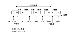
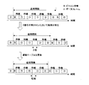
- FIG. 2 is an explanatory diagram of a data frame transmission method.
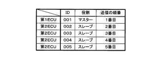
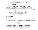
- FIG. 3 is a chart showing the IDs, roles, and order of transmission of the 1ECU11 and (N-1) 2ECU12. ID is an abbreviation for Identification Data. In FIGS. 2 and 3, an example in which N is 5 is shown.
- Each of the 1ECU 11 and the (N ⁇ 1) 2ECU 12 transmits data frames according to, for example, the PLCA (Physical Layer Collision Avoidance) method.
- a beacon signal is repeatedly transmitted over communication bus B.
- FIG. 2 When the beacon signal is transmitted, five data frames are transmitted over communication bus B.
- a beacon signal indicates the start of transmission of a data frame.
- a beacon signal is transmitted by an ECU that acts as a master.
- the first ECU 11 serves as a master and repeatedly transmits beacon signals via the communication bus B.
- Each of the (N ⁇ 1) second 2ECUs 12 plays the role of a slave.
- the 1ECU11 and the (N-1) 2ECU12 transmit data frames according to a predetermined order.
- an ID is assigned in advance to each of the 1ECU11 and the (N-1) 2ECU12.
- the ID of the first ECU11 is 001.
- One of 002 to 005 is assigned to each of the four 2ECU12.
- the order of transmission of each of 001 to 005 is set to 1st to 5th.
- the transmission order of the master is first.
- the 1ECU11 transmits a beacon signal
- the 1ECU11 whose ID is 001 transmits a data frame.
- the second 2ECU 12 whose ID is 002 transmits a data frame.
- the three 2ECU12 corresponding to 003-005 sequentially transmit the data frame.
- the first 1ECU11 transmits the beacon signal again when the second 2ECU12 whose ID is 005 finishes transmitting the data frame.
- the first ECU 11 waits until the waiting period elapses after completing the transmission of the beacon signal.
- the waiting period is a constant value and preset.
- the first ECU11 transmits a data frame when the waiting period has passed.
- Each 2ECU12 waits until the waiting period elapses after the transmission of the data frame is completed.
- Each 2ECU12 when the waiting period has elapsed, transmits a data frame.
- the standby period corresponds to the first predetermined period and the second predetermined period.
- the 1ECU11 that plays the role of the master and the (N-1) 2ECU12 that plays the role of the slave synchronize using the beacon signal, thereby preventing data collision. Avoided.
- N is different from 5
- the first 1ECU11 and the (N-1) second 2ECU12 transmit data frames according to a predetermined order, as in the case where N is 5.
- FIG. 4 is a waveform diagram of a beacon signal.
- the vertical and horizontal axes of FIG. 4 indicate the voltage difference and time, respectively.
- the waveform of the beacon signal shown in FIG. 4 is an example.
- the communication bus B includes a first conductor W1 and a second conductor W2 (see FIG. 7).
- the first conductor W1 and the second conductor W2 are twisted together. This realizes a twisted pair line.
- a beacon signal consists of a plurality of bits.
- Each of the 1ECU 11 and the (N ⁇ 1) 2ECU 12 converts the voltage difference between the first conducting wire W1 and the second conducting wire W2 included in the communication bus B into a high level voltage or a low level voltage each time a 1-bit period elapses. to transmit a beacon signal.
- high level voltage and low level voltage are indicated by H and L, respectively.
- Each of the 1ECU 11 and the (N ⁇ 1) 2ECU 12 converts the voltage difference between the first conducting wire W1 and the second conducting wire W2 included in the communication bus B to a high level voltage or a low level each time a 1-bit period elapses. Transmit data frames by adjusting the voltage.
- Each bit indicates a high level voltage or a low level voltage.
- the beacon signal consists of 7 bits. A high level voltage and a low level voltage are alternately output. Note that the number of bits forming the beacon signal is not limited to seven.
- the waveform of the beacon signal is predetermined.
- the 1ECU11 transmits a beacon signal via the communication bus B
- all the 2ECU12 receive the beacon signal.
- a clock signal composed of a high-level voltage and a low-level voltage is output.
- a clock signal periodically rises or falls in voltage.
- a voltage rise is a switch from a low level voltage to a high level voltage.
- a voltage fall is a switch from a high level voltage to a low level voltage.
- Each 2ECU12 when receiving the beacon signal, adjusts the rising or falling time of the clock signal.
- Each of the second 2ECU 12 for example, adjusts the rising or falling time point to the end time point of the beacon signal.
- the rising edge of the clock signal is adjusted.
- the time point of the falling edge of the clock signal is adjusted.
- Synchronization between the first ECU 11 and the (N ⁇ 1) second ECUs 12 is realized by each second ECU 12 adjusting the timing of the rise or fall of the clock signal. As a result, the timings at which the first 1ECU11 and the (N-1) second 2ECU12 execute the processes substantially match.
- the waveform of the beacon signal is not limited to the waveform shown in FIG.
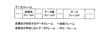
- FIG. 5 is an explanatory diagram of the contents of the data frame.
- a data frame includes a destination field, a data length field and a data field.
- a data frame is data and consists of a plurality of bits. Each bit outputs a high level voltage or a low level voltage. Bit values of 1 and 0 respectively correspond to high and low voltages, for example.
- the destination field of the data frame indicates the destination of the data frame. For example, an ID is indicated in the destination field.
- the data field of the data frame contains the main data. As described above, the main data are, for example, sensor detection values.
- the data length field of the data frame indicates the length of the main data. The unit of length of main data is bits.
- the number of bits that make up the part other than the data field is fixed. Once the length of the main data is determined, the length of the data frame is determined. The number of bits that make up the main data varies. However, the upper limit of the number of bits forming the main data is predetermined.
- Each of the first 1ECU 11 and the (N-1) second 2ECUs 12 transmits a data frame whose transmission destination is in an ECU other than the transmission source among the ECUs connected to the communication bus B.
- This data frame is hereinafter referred to as a transmission frame.
- a transmission frame corresponds to transmission data.
- a data frame containing failure data is a transmission frame.
- the destination of the transmission frame transmitted by the 1ECU11 whose ID is 001 is at least one of the four 2ECU12 corresponding to 002 to 005. is.
- the destination of the transmission frame transmitted by the 2ECU12 whose ID is 002 is at least one of the 1ECU11 corresponding to 001 and the three 2ECU12 corresponding to 003 to 005.
- Each of the first 1ECU11 and the (N-1) second 2ECU12 further transmits a data frame whose destination is different from that of the first 1ECU11 and the (N-1) second 2ECU12.
- This data frame is hereinafter referred to as a dummy frame.
- a dummy frame corresponds to dummy data.
- the destination of the dummy frame is different from any of the first 1ECU11 corresponding to 001 and the four second 2ECU12 corresponding to 002 to 005.
- the destination of the dummy frame is, for example, the ECU whose ID is 999.
- each of the 1ECU 11 and the (N-1) 2ECU 12 discards the received data frame when the destination of the data frame is different from its own device when the data frame is received. Therefore, when a dummy frame is transmitted, each of the 1ECU11 and the (N-1) 2ECU12 discards the received dummy frame.
- the transmission destination of the dummy frame is different from any of the ECUs connected to the communication bus B other than the transmission source.
- FIG. 6 is a block diagram showing the main configuration of the 1ECU 11.
- the first ECU 11 has a communication IC 21 , an input section 22 , an output section 23 , a device storage section 24 and a device control section 25 .
- IC is an abbreviation for Integrated Circuit.
- Communication IC 21 , input section 22 , output section 23 , device storage section 24 and device control section 25 are connected to device bus 26 .
- Communication IC 21 is further connected to communication bus B.
- the input 22 is also connected to sensors.
- the output unit 23 is also connected to electrical equipment. Illustrations of sensors and electrical equipment are omitted.
- the sensor outputs the detected value to the input unit 22.
- the device control unit 25 When a sensor detection value is input to the input unit 22, the device control unit 25 generates a transmission frame including the sensor detection value as main data.
- the device control unit 25 gives the generated transmission frame to the communication IC 21 .
- the communication IC 21 transmits the given transmission frame via the communication bus B when the transmission frame is given.
- the communication IC 21 receives the data frame transmitted via the communication bus B.
- the communication IC 21 discards the received data frame. Therefore, when the communication IC 21 receives a dummy frame, it discards the received dummy frame.
- the communication IC 21 gives the received data frame to the device control unit 25 when the destination of the received data frame is the first ECU 11 .
- a data frame whose destination is the first ECU 11 is a transmission frame.
- the destination of the data frame containing the failure data is the 2ECU12. For this reason, failure data is never included in a transmission frame whose transmission destination is the first ECU 11 .
- the device control unit 25 determines the operation to be performed by the electrical device based on the main data of the given transmission frame. When the operation to be performed by the electrical equipment is determined, the device control unit 25 instructs the output unit 23 to output an operation signal indicating the determined operation to the electrical equipment. As described above, when an operation signal is input, the electric device performs an operation indicated by the input operation signal.
- the communication IC 21 detects a failure of the 2ECU 12.
- Communication IC21 when detecting a failure of the second 2ECU12, transmits a transmission frame including failure data.
- the destination of this transmission frame is the normal 2ECU12.
- the device storage unit 24 is, for example, a non-volatile memory.
- a computer program P is stored in the device storage unit 24 .
- the device control unit 25 has a processing element that executes processing, such as a CPU (Central Processing Unit). By executing the computer program P, the processing element of the device control unit 25 executes transmission frame generation processing and signal output processing in parallel.
- the transmission frame generation process the device control unit 25 generates a transmission frame as described above and gives the generated transmission frame to the communication IC 21 .
- the device control section 25 instructs the output section 23 to output an operation signal as described above.
- the computer program P may be provided to the first ECU 11 using a non-temporary storage medium A that records the computer program P in a readable manner.
- Storage medium A is, for example, a portable memory. Examples of portable memory include CD-ROM, USB (Universal Serial Bus) memory, SD card, micro SD card, compact flash (registered trademark), and the like.
- the processing element of the device controller 25 may read the computer program P from the storage medium A using a reading device (not shown).
- the read computer program P is stored in the device storage unit 24 .
- the computer program P may be provided to the first ECU 11 by the communication unit (not shown) of the first ECU 11 communicating with an external device. In this case, the processing element of the device control section 25 acquires the computer program P through the communication section.
- the acquired computer program P is stored in the device storage unit 24 .
- the communication IC 21 has an IC control section 31 , an interface 32 , an IC storage section 33 , a clock section 34 and a bit communication device 35 . These are connected to the IC bus 36 . Interface 32 is also connected to device bus 26 . The clock section 34 is further connected to the bit communicator 35 . The bit communicator 35 is also connected to the communication bus B;
- the device control section 25 gives the transmission frame to the IC control section 31 via the interface 32 .
- the IC control unit 31 has a processing element such as a CPU that executes processing, and functions as a processing unit.
- the IC control section 31 writes the given transmission frame to the IC storage section 33 .
- the IC storage unit 33 is, for example, a nonvolatile memory. A dummy frame is stored in advance in the IC storage unit 33 .
- the IC control unit 31 detects a failure of the 2ECU 12. When the IC control unit 31 detects a failure of the 2ECU12, it generates a transmission frame including failure data indicating the failed 2ECU12. The IC control section 31 writes the generated transmission frame to the IC storage section 33 .
- the clock unit 34 outputs a clock signal to the bit communication device 35 .
- the IC control unit 31 supplies the transmission frame or dummy frame stored in the IC storage unit 33 to the bit communication unit 35 bit by bit.
- the IC control unit 31 gives the beacon signal to the bit communication device 35 bit by bit.
- the bit communication device 35 transmits a 1-bit signal or data given from the IC control unit 31 each time the clock signal rises.
- the bit communicator 35 transmits 1-bit signal or data by adjusting the voltage difference between the first conductor W1 and the second conductor W2 included in the communication bus B to a high level voltage or a low level voltage.
- the voltage difference is maintained at the high level voltage or the low level voltage during one period of the clock signal.
- the period of the clock signal corresponds to the period of one bit.
- the bit communication device 35 receives a 1-bit signal or data by detecting the voltage difference between the first conducting wire W1 and the second conducting wire W2 included in the communication bus B each time the clock signal rises.
- the bit communication device 35 notifies the IC control unit 31 of the received 1-bit signal or data.
- bit communication device 35 may transmit 1-bit data given from the IC control section 31 each time the clock signal falls.
- the bit communicator 35 may also receive a 1-bit signal or data by detecting the voltage difference of the communication bus B each time the clock signal falls.
- the IC control unit 31 discards the received data frame. Therefore, when the bit communication device 35 receives a dummy frame, the IC control section 31 discards the received dummy frame.
- the IC control unit 31 provides the received data frame to the device control unit 25 via the interface 32. .
- the data frame that the IC control section 31 gives to the device control section 25 is a transmission frame.
- a computer program (not shown) is stored in the IC storage unit 33 .
- the IC control unit 31 concurrently executes write processing, transmission processing, reception processing, failure detection processing, and update processing by executing a computer program.
- the IC control unit 31 writes the transmission frame to the IC storage unit 33 as described above.
- the IC control unit 31 causes the bit communication device 35 to transmit a beacon signal.
- the IC control unit 31 causes the bit communicator 35 to transmit a transmission frame or a dummy frame.
- the IC control unit 31 executes the process related to the data frame received by the bit communication device 35, as described above.
- the failure detection process the IC control unit 31 detects failure of the 2ECU12.
- the IC control unit 31 updates the order table.
- the IC storage unit 33 stores an order table indicating the order of transmission performed by the 1ECU 11 and the (N-1) 2ECU 12.
- the IC control unit 31 causes the bit communication device 35 to transmit transmission frames or dummy frames according to the order indicated by the order table.
- the order table as shown in FIG. 3, the order of transmission is shown in association with each of the N IDs.
- FIG. 7 is a circuit diagram of the bit communicator 35.
- the bit communication device 35 has three resistors 41a, 41b, 42, three capacitors 43, 44a, 44b, a common mode choke coil 45 and a converter 46.
- the common mode choke coil 45 has a first inductor 45a, a second inductor 45b and an annular magnetic body. Each of the first inductor 45a and the second inductor 45b is wound around a magnetic material.
- the conversion unit 46 of the bit communication device 35 is connected to the first conductor W1 of the communication bus B by the equipment conductor Wa.
- the conversion unit 46 of the bit communication device 35 is connected to the second conductor W2 of the communication bus B by the equipment conductor Wb.
- the conversion section 46 is also connected to the clock section 34 and the IC bus 36 .
- a capacitor 44a and a first inductor 45a are arranged in the middle of the equipment lead wire Wa.
- the capacitor 44a is arranged on the first conductor W1 side of the first inductor 45a.
- a capacitor 44b and a second inductor 45b are arranged in the middle of the equipment lead wire Wb.
- the capacitor 44b is arranged on the second conductor W2 side of the second inductor 45b.
- One end of the resistor 41a is connected to the equipment lead wire Wa on the side of the first lead wire W1 of the capacitor 44a.
- one end of the resistor 41b is connected to the equipment lead wire Wb on the second lead wire W2 side of the capacitor 44b.
- the other end of resistor 41a is connected to the other end of resistor 41b.
- a connection node between the resistors 41 a and 41 b is connected to one ends of the resistor 42 and the capacitor 43 .
- the other ends of the resistor 42 and the capacitor 43 are connected to the first conductor G1.
- the 1st conductor G1 is arrange
- the resistors 41a, 41b, 42 and the capacitor 43 function as a terminating circuit to suppress reflection of signals or data represented by the voltage difference between the first conductor W1 and the second conductor W2.
- the two capacitors 44a and 44b respectively remove DC components from the two voltages input from the two equipment leads Wa and Wb.
- Capacitors 44 a and 44 b output two voltages from which DC components have been removed to common mode choke coil 45 .
- the common mode choke coil 45 removes common mode noise from the two voltages output by the capacitors 44 a and 44 b and outputs the two voltages from which the common mode noise has been removed to the conversion section 46 .
- the conversion unit 46 detects the voltage difference between the two voltages input from the common mode choke coil 45 each time the clock signal input from the clock unit 34 rises or falls. When the voltage difference is detected, the converter 46 outputs a bit value corresponding to the detected voltage difference to the IC controller 31 .
- Bit values are zero or one. For example, if the voltage difference is a low level voltage, zero is output as the bit value. If the voltage difference is a high level voltage, 1 is output as the bit value.
- a bit value is represented by a voltage whose reference potential is the potential of the second conductor G2. Bit values of 1 and 0 respectively correspond to, for example, high-level and low-level voltages whose reference potential is the second conductor G2.
- the second conductor G2 is arranged inside the first ECU 11 and is different from the first conductor G1.
- the bit communicator 35 transmits 1-bit signal or data.
- the IC control section 31 gives a 1-bit signal or data to the conversion section 46 .
- the conversion unit 46 converts the voltage difference between the two device conductors Wa and Wb into a 1-bit signal or data given from the IC control unit 31 each time the clock signal input from the clock unit 34 rises or falls. Adjust the voltage to correspond to
- the two voltages output from the converter 46 are input to the common mode choke coil 45 .
- the common mode choke coil 45 removes common mode noise from the two voltages output by the converter 46, and outputs the two voltages from which the common mode noise has been removed to the two capacitors 44a and 44b.
- the two capacitors 44 a and 44 b remove DC components from the two voltages input from the common mode choke coil 45 .
- Capacitors 44a and 44b apply two voltages from which DC components have been removed to first conductor W1 and second conductor W2 of communication bus B, respectively. Thereby, the voltage difference between the first conducting wire W1 and the second conducting wire W2 is adjusted to a high level voltage or a low level voltage.
- the configuration of the bit communication device 35 conforms to 10BASE-T1S of IEEE802.3cg (IEEE is a registered trademark). Therefore, the bit communicator 35 is configured to realize the transmission of baseband signals with a data rate of 10 Mbps.
- the baseband signal is transmitted via a twisted wire pair composed of a first conducting wire W1 and a second conducting wire W2.
- IEEE is an abbreviation for Institute of Electrical and Electronics Engineers.
- the IC control unit 31 discards the received data frame. Therefore, when the bit communication device 35 receives a dummy frame, the IC control section 31 discards the received dummy frame.
- the IC control unit 31 determines whether the main data of the data frame is failure data. judge.
- the IC storage unit 33 stores failure data. If no secondary 2ECU 12 is faulty, the fault data indicates no fault. When determining that the main data is failure data, the IC control unit 31 updates the failure data stored in the IC storage unit 33 to the failure data included in the received data frame. When the IC control section 31 determines that the main data is not the failure data, the IC control section 31 gives the received data frame to the device control section 25 via the interface 32 .
- the IC control unit 31 does not give the beacon signal to the bit communication device 35.
- Bit communicator 35 receives the beacon signal.
- the IC control unit 31 adjusts the rising or falling timing of the clock signal based on the received beacon signal, as described in the description of the beacon signal. In configurations where processing is performed at the rising edge of the clock signal, the rising edge of the clock signal is adjusted. In a configuration where processing is executed at the time of the falling edge of the clock signal, the time point of the falling edge of the clock signal is adjusted.
- the IC control unit 31 of the 2ECU executes writing processing, transmission processing, and update processing. However, in the transmission process of the second ECU 12, the IC control unit 31 adjusts the clock signal based on the beacon signal received by the bit communicator 35, and then causes the bit communicator 35 to transmit a transmission frame or a dummy frame. . In the reception process of the 2ECU12, the IC control unit 31 performs the process related to the data frame received by the bit communication device 35, as described above. The IC control unit 31 of the 2ECU12 never detects a failure.
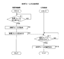
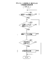
- FIG. 8 is a flow chart showing a procedure for preparation for transmission of a transmission frame. In each of the first 1ECU11 and (N-1) second 2ECU12, preparation for transmission of the transmission frame is performed in the same manner.
- FIG. 8 shows transmission frame generation processing of the device control unit 25 and writing processing of the IC control unit 31 .
- the device control unit 25 first determines whether or not to generate a transmission frame (step S1). In step S ⁇ b>1 , the device control unit 25 determines to generate a transmission frame when, for example, a sensor detection value is input to the input unit 22 . In this case, the main data of the transmission frame is the sensor detection value input to the input unit 22 . When determining not to generate a transmission frame (S1: NO), the device control unit 25 executes step S1 again and waits until the timing of generating a transmission frame arrives.
- the device control unit 25 When the device control unit 25 determines to generate a transmission frame (S1: YES), it generates a transmission frame (step S2). For example, each time step S2 is executed, the device control unit 25 may always generate a transmission frame having a predetermined data length.
- the predetermined length is, for example, the upper limit of the number of bits forming the data field of the data frame.
- the data length is fixed, the number of bits forming the transmission frame generated by the device control section 25 is always constant.
- the data length of the dummy frame may also be the predetermined length. In this case, the number of bits forming the dummy frame is the same as the number of bits forming the transmission frame.
- the device control section 25 gives the transmission frame generated in step S2 to the IC control section 31 via the interface 32 (step S3). After executing step S3, the device control unit 25 ends the transmission frame generation process. After completing the transmission frame generation process, the device control unit 25 executes the transmission frame generation process again.
- the IC control unit 31 first determines whether or not a transmission frame has been given from the device control unit 25 (step S11). When the IC control section 31 determines that the transmission frame is not given (S11: NO), the IC control section 31 executes step S11 again and waits until the device control section 25 gives the transmission frame.
- the IC control section 31 determines that the transmission frame has been given from the device control section 25 (S11: YES), it writes the given transmission frame to the IC storage section 33 (step S12). After executing step S12, the IC control unit 31 terminates the write process. After completing the write process, the IC control unit 31 executes the write process again.
- the device control unit 25 when the device control unit 25 generates a transmission frame, the generated transmission frame is written to the IC storage unit 33. A transmission frame stored in the IC storage unit 33 is transmitted via the communication bus B. FIG.
- FIG. 9 is a flowchart showing the procedure of transmission processing executed by the IC control unit 31 of the first ECU 11.
- the IC control unit 31 of the first ECU 11 first determines whether or not to transmit a beacon signal (step S21).
- the waiting period has passed, if the second 2ECU 12 whose order is the last starts transmitting the data frame, the time when this second 2ECU 12 finishes transmitting the data frame is the timing at which the beacon signal is transmitted.
- the waiting period has elapsed, if the second 2ECU12 whose turn is the last does not start transmitting the data frame, the time when the waiting period has elapsed is the timing at which the beacon signal is transmitted.
- the data length field of the data frame indicates the data length of the main data.
- IC control unit 31 based on the data length indicated in the data length field of the data frame that is being transmitted by the last 2ECU12, it is possible to grasp the timing of the end of the transmission of the data frame.
- step S21 When the IC control unit 31 determines not to transmit the beacon signal (S21: NO), it executes step S21 again and waits until the timing of transmitting the beacon signal arrives.
- the IC control unit 31 determines to transmit the beacon signal (S21: YES), it instructs the bit communication device 35 to transmit the beacon signal via the communication bus B (step S22). As described above, in the second ECU 12, when the bit communication device 35 receives the beacon signal, the IC control unit 31 adjusts the clock signal.
- step S23 the IC control unit 31 determines whether or not it is time to start transmitting the data frame (step S23). Since the 1ECU11 serves as a master, the transmission order of the 1ECU11 is first. In this case, in step S23, the IC control unit 31 determines whether or not the standby period has elapsed after the transmission of the beacon signal is completed. The timing at which the waiting period has elapsed is the timing at which transmission is started. If the IC control unit 31 determines that it is not the timing to start transmission (S23: NO), it executes step S23 again and waits until the timing to start transmission arrives.
- the IC control unit 31 determines whether it is time to start transmission (S23: YES). If the IC control section 31 determines that the transmission frame is stored in the IC storage section 33 (S24: YES), it instructs the bit communication device 35 to transmit the transmission frame stored in the IC storage section 33 to Bit by bit is transmitted through the communication bus B (step S25). The bit communicator 35 functions as a data transmitter. After executing step S25, the IC control unit 31 deletes the transmitted transmission frame from the IC storage unit 33 (step S26).
- the IC control unit 31 determines that the transmission frame is not stored in the IC storage unit 33 (S24: NO), the IC control unit 31 instructs the bit communication device 35 to set the dummy frame stored in the IC storage unit 33 to 1. Bit by bit is transmitted (step S27). After executing one of steps S26 and S27, the IC control unit 31 terminates the transmission process. After completing the transmission process, the IC control unit 31 executes the transmission process again. Since the transmission process is repeatedly executed, the bit communication device 35 repeatedly transmits the beacon signal. The bit communicator 35 also functions as a signal transmitter.
- FIG. 10 is a flowchart showing the procedure of transmission processing executed by the IC control unit 31 of the second ECU 12. Steps S34 to S37 of the transmission process executed by the IC control unit 31 of the 2ECU12 are the same as steps S24 to S27 of the transmission process executed by the IC control unit 31 of the 1ECU11. Therefore, description of steps S34 to S37 is omitted.
- the IC control unit 31 of the second ECU 12 first determines whether or not the bit communication device 35 has received the beacon signal (step S31). When the IC control unit 31 determines that the bit communicator 35 has not received the beacon signal (S31: NO), it executes step S31 again and waits until the bit communicator 35 receives the beacon signal.
- the IC control unit 31 determines that the bit communication device 35 has received the beacon signal (S31: YES), it adjusts the clock signal output by the clock unit 34 (step S32). At step S32, the IC control unit 31 adjusts the timing of the rise or fall of the clock signal as described above. After executing step S32, the IC control unit 31 determines whether or not it is time to start transmitting a data frame (step S33).
- step S33 the IC control unit 31 selects the first 1ECU11 or the second 2ECU12, which is one ahead in the order table, when the standby period has elapsed. has started transmitting a data frame.
- the timing of starting the transmission is when the waiting period has passed after the 1ECU11 or the 2ECU12, which is one before the order, finishes transmitting the data frame.
- the waiting period has passed, if the first 1ECU11 or the second 2ECU12, which is one ahead in the order, does not start transmitting the data frame, when the waiting period has passed from this time point, the data frame transmission starts. It's time to.
- the ECU that is one before in order is the 1ECU 11 whose ID is 001.
- the ECU whose order is one before is the 2ECU12 whose ID is 002.
- the IC control unit 31 based on the data length indicated in the data length field of the data frame being transmitted by the 1ECU11 or 2ECU12, which is one before in the order, the 1ECU11 or 2ECU12 ends the transmission of the data frame. You can figure out when to do it.
- step S33 When the IC control unit 31 determines that it is not the timing to start transmitting the data frame (S33: NO), it executes step S33 and waits until the timing to start transmitting the data frame arrives. When the IC control unit 31 determines that it is time to start transmitting the data frame (S33: YES), the IC control unit 31 executes step S34. After completing the transmission process, the IC control unit 31 executes the transmission process again.
- the bit communication device 35 of each of the first 1ECU 11 and the (N-1) second 2ECU 12 has a dummy frame to send. Therefore, the bit communication device 35 of each of the 1ECU11 and the (N-1) 2ECU12 always transmits a transmission frame or a dummy frame when the turn of transmission comes.
- the order of transmitting the data frames is predetermined as shown in FIG. Therefore, the bit communicators 35 of the first 1ECU11 and the (N-1) second 2ECU12 transmit data frames via the communication bus B according to a predetermined order when the beacon signal is transmitted.
- the beacon signal indicates the start of data frame transmission performed by the bit communicators 35 of the 1ECU 11 and the (N ⁇ 1) 2ECU 12 .
- Each of the 1ECU11 and the 2ECU12 functions as a communication device that transmits data.
- the 2ECU12 also functions as a second communication device.
- FIG. 11 is a flow chart showing the procedure of failure detection processing.
- the failure detection process is executed by the IC control section 31 of the first ECU 11 .
- the IC control unit 31 executes the failure detection process again.
- the value of the integer K is stored in the IC storage unit 33 .
- the value of integer K is changed by IC control section 31 .
- the failure data is stored in the IC storage unit 33 of the first ECU11.
- the second ECU 12 indicated by the failure data is updated by the IC control unit 31 . As described above, if there is no faulty second 2ECU 12, the fault data indicates no fault.
- the IC control unit 31 of the 1ECU 11 determines whether each of the (N-1) 2ECUs 12 has transmitted a data frame.
- the second 2ECU12 functions as a target communication device.
- the IC storage unit 33 stores the number of times of determination that the data frame was not transmitted.
- Each of the (N ⁇ 1) number of determinations is changed by the IC control section 31 .
- the number of (N-1) determinations is zero.
- the IC control unit 31 of the first ECU 11 first changes the value of the integer K to 2 (step S41). Next, the IC control unit 31 determines whether or not it is the transmission timing of the K-th 2ECU 12 (step S42).
- the Kth is the order of transmitting the data frames, indicated by the order table.
- the transmission timing is the timing of transmitting the data frame.
- step S42 determines whether the K-th 2ECU12 has transmitted the data frame (step S43).
- a data frame transmitted by one ECU connected to communication bus B is received by all ECUs connected to communication bus B. Therefore, when the bit communication device 35 has not received the data frame, the IC control unit 31 determines that the K-th 2ECU 12 has not transmitted the data frame. When the bit communication device 35 receives the data frame, the IC control unit 31 determines that the K-th 2ECU 12 has transmitted the data frame.
- the IC control unit 31 determines whether or not the number of determinations of the K-th 2ECU 12 is a predetermined number of times (step S45).
- the predetermined number of times is a constant value of 2 or more.
- the failure data is updated assuming that a failure has occurred in the K-th 2ECU 12 (step S46).
- the IC control unit 31 adds the K-th 2ECU12 to the 2ECU12 indicated by the failure data. In the failure data, the K-th 2ECU 12 is indicated by ID.
- the IC control unit 31 determines that the K-th 2ECU 12 has transmitted the data frame (S43: YES), it changes the determination count of the K-th 2ECU 12 to zero (step S47).
- the IC control unit 31 determines that the number of determinations of the K-th second 2ECU 12 is less than the predetermined number (S45: NO), or after executing one of steps S46 and S47, the integer K is incremented by 1. (Step S48).
- the IC control unit 31 determines whether or not the value of the integer K is N (step S49).
- the IC control unit 31 determines that the value of the integer K is not N (S49: NO)
- the IC control unit 31 determines whether each of the (N-1) second 2ECU 12 from the second to the N-th has transmitted the data frame.
- the IC control unit 31 determines whether or not the failure data has been updated in the current failure detection process (step S50). If the IC control unit 31 determines that the failure data has been updated (S50: YES), it writes a transmission frame including the failure data to the IC storage unit 33 (step S51). As a result, the bit communication device 35 transmits the transmission frame including the failure data via the communication bus B.
- FIG. Failure data is stored in the IC storage unit 33 of the second ECU 12 . In the second ECU 12, when the bit communication device 35 receives a transmission frame containing failure data, the IC control unit 31 includes the failure data stored in the IC storage unit 33 in the transmission frame received by the bit communication device 35. Update to the failure data that is available.
- the IC control unit 31 determines that the failure data has not been updated (S50: NO), or after executing step S51, it ends the failure detection process. As described above, after completing the failure detection process, the IC control unit 31 executes the failure detection process again.
- FIG. 12 is a flowchart showing the procedure of update processing.
- the update process is executed by the IC control units 31 of the 1ECU11 and the (N ⁇ 1) 2ECU12.
- the IC control unit 31 determines whether or not the failure data stored in the IC storage unit 33 has been updated (step S61). If the IC control unit 31 determines that the failure data has not been updated (S61: NO), the IC control unit 31 executes step S61 again and waits until the failure data is updated in the IC storage unit 33.
- step S62 determines whether it is time to update the order table. If the IC control unit 31 determines that it is not the update timing of the order table (S62: NO), it executes step S62 again and waits until the update timing of the order table arrives.
- the update timing is, for example, the timing when the communication IC 21 is activated or the timing when transmission of the next beacon signal is started.
- the IC control unit 31 updates the order table based on the failure data stored in the IC storage unit 33 (step S63).
- FIG. 13 is an explanatory diagram of updating the order table.
- each ID is associated with the order of data frame transmission.
- 001 to 005 correspond to the 1st to 5th, respectively.
- the IC control unit 31 deletes the column of 003 in the order table.
- the 3rd is deleted, so the 4th and 5th are changed to the 3rd and 4th, respectively.
- the first 1ECU11 and the three normal second 2ECU12 transmit data frames assuming that the 003 second 2ECU12 does not exist.
- the IC control unit 31 ends the update process after executing step S63. After completing the update process, the IC control unit 31 executes the update process again.
- the IC control unit 31 of the first 1ECU 11 determines that the target communication device included in the (N-1) second 2ECU 12 has not transmitted data a predetermined number of times in succession. Detect faults. Therefore, the possibility of erroneously detecting a failure of the target communication device is low.
- the IC control unit 31 of the 1ECU 11 When the IC control unit 31 of the 1ECU 11 detects a failure of the target communication device, it updates the failure data, instructs the bit communication device 35, and sends the updated failure data to the remaining 2ECU 12 other than the target communication device. send. As a result, the remaining failure data of the 2ECU12 are updated and match the failure data of the 1ECU11. After that, the 1ECU11 and the normal 2ECU12 update the transmission order indicated by the order table to the order in which the target communication device is removed, based on the updated failure data.
- the first ECU11 also functions as a communication device that changes the order.
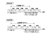
- FIG. 14 is an explanatory diagram of the effect of the communication system 1.
- FIG. 14 an example in which N is 5 is shown.
- the first ECU 11 and the (N-1) second ECU 12 are operating normally, as shown in the upper part of FIG. 2ECU12 transmits the data frame according to the order indicated by the order table.
- the 1ECU11 transmits the beacon signal again.
- the third 2ECU 12 stops transmitting data frames.
- the third 2ECU12 does not transmit the data frame. Therefore, furthermore, the fourth 2ECU12 transmits the data frame when the waiting period has elapsed. Therefore, after the second 2ECU12 ends the transmission of the data frame, after the waiting period has passed twice, the fourth 2ECU12 starts transmitting the data frame.
- the third 2ECU12 does not transmit a data frame, so the 1ECU11 can detect the failure of the third 2ECU12.
- the failure data is updated to indicate the 3rd 2ECU12 as the 2ECU12 that is in failure.
- the 1ECU11 transmits a transmission frame containing the failure data, and the failure of the 3rd 2ECU12 is notified to the 2nd, 4th and 5th 2ECU12.
- the order indicated by the order table is updated in the 1ECU11 and the 2nd, 4th and 5th 2ECU12.
- the 1ECU 11 and the (N-2) 2ECU 12 transmit data frames according to the order indicated by the updated order table. Since the standby period does not elapse twice, the transmission interval at which the beacon signal is transmitted is shortened. The amount of data transmitted per unit time via the communication bus B is almost the same as the amount of data before the failure occurred.
- Embodiment 2 In Embodiment 1, the waiting period is unchanged. However, the waiting period may be changed according to the number of failed 2ECU12. Below, the points of the second embodiment that are different from the first embodiment will be described. Configurations other than those described later are the same as those of the first embodiment, so the same reference numerals as those of the first embodiment are given to the components that are common to the first embodiment, and the description thereof will be omitted.
- FIG. 15 is a block diagram showing the main configuration of the first ECU 11 according to the second embodiment.
- the IC storage unit 33 of the first ECU 11 stores a standby period table and device number data.
- the number of normal ECUs in the 1ECU11 and the (N-1) 2ECU12 will be referred to as the number of devices.
- the device number data indicates the number of devices. The number of devices indicated by the device count data is changed by the IC control section 31 .
- FIG. 16 is a chart showing the contents of the waiting period table.
- the waiting period table shows the relationship between the number of devices and the waiting period. As shown in FIG. 16, the smaller the number of devices, the longer the waiting period. FIG. 16 shows an example where N is five.
- the waiting period in which the IC control unit 31 of the first ECU 11 waits is a waiting period corresponding to the number of devices indicated by the device number data.
- the IC storage unit 33 of the 2ECU 12 also stores the standby period table and the number of devices data.
- the standby period table stored in the IC storage unit 33 of the first ECU11 and the (N ⁇ 1) second ECU12 are the same.
- the waiting period in which the IC control unit 31 of the second ECU 12 waits is also a waiting period corresponding to the number of devices indicated by the device number data.
- FIG. 17 is a flowchart showing the procedure of update processing.
- the update process is executed by the IC control units 31 of the 1ECU11 and the (N ⁇ 1) 2ECU12.
- the IC control unit 31 executes steps S61 to S63 of update processing in the same manner as in the first embodiment. Therefore, description of steps S61 to S63 is omitted.
- the IC control unit 31 adjusts the number of devices indicated by the device number data to a value calculated by subtracting the number of the second 2ECU 12 indicated by the failure data from N (step S71).
- the IC control unit 31 terminates the update process.
- the IC control unit 31 executes the update process again.
- the IC control unit 31 of the 1ECU 11 updates the failure data when determining that the target communication device did not transmit the data frame a plurality of times in succession.
- the IC control unit 31 of the 1ECU11 further instructs the bit communication device 35 to transmit the updated failure data to the remaining 2ECU12 other than the target communication device.
- the remaining failure data of the 2ECU12 are updated and match the failure data of the 1ECU11.
- the failure data is updated, the number of devices is reduced. As a result, the standby period of the 1ECU11 and the normal 2ECU12 is extended.
- FIG. 18 is an explanatory diagram of the effect of the communication system 1.
- FIG. 18 an example in which N is 5 is shown.
- the (N-1) second 2ECU 12 transmits data frames according to the order indicated by the order table.
- the fourth 2ECU12 transmits the data frame. Start. After that, the fault data is updated, and the 1ECU 11 and the (N-2) normal 2ECUs 12 transmit data frames according to the order indicated by the order table.
- the communication system 1 of the second embodiment has the same effects as those of the communication system 1 of the first embodiment except for the effect obtained by maintaining the standby period constant regardless of the number of devices.
- FIG. 19 is an explanatory diagram of features of the communication system 1 according to the first and second embodiments.
- FIG. 19 shows transmission of data frames after the order table has been updated in each of the first and second embodiments (see the lower part of FIGS. 14 and 18).
- the first 1ECU 11 and the (N ⁇ 2) second 2ECUs 12 transmit data frames in order, assuming that there is no failed second 2ECU 12 .
- the voltage difference between the first conducting wire W1 and the second conducting wire W2 is switched to a low level voltage or a high level voltage.
- the sum of the number of times the high-level voltage is switched to the low-level voltage and the number of times the low-level voltage is switched to the high-level voltage is referred to as the number of times the voltage of the communication bus B is switched.
- the communication bus B When the voltage of the communication bus B is switched, the communication bus B generates disturbance noise. Disturbance noise is noise that interferes with a signal output via a conductor different from the communication bus B. FIG. If the disturbance noise is large, there is a possibility that a signal output via a conductor other than the communication bus B, such as an operating signal, is erroneously read.
- the communication system 1 when a failure occurs in one 2ECU 12, the waiting period is not changed, so the beacon signal transmission interval is reduced. As a result, the amount of data transmitted per unit time is almost the same as the amount of data before the failure occurred. However, since the transmission interval of the beacon signal is reduced, the communication bus B increases the number of times of switching per unit time. Therefore, the intensity of disturbance noise increases.
- the standby period is extended, so the amount of data transmitted per unit time is the same as before the failure occurs. Decrease from the amount of data.
- the transmission interval of the beacon signal does not change, the number of times of switching per unit time in the communication bus B hardly changes. As a result, the intensity of disturbance noise hardly changes.
- FIG. 20 is an explanatory diagram of another feature of the communication system 1 in the first and second embodiments.
- FIG. 20 shows the spectrum of the signal (data) propagating through the communication bus B before a failure occurs in the 2ECU12. Frequency and intensity are shown on the horizontal and vertical axes, respectively.
- a plurality of spectra are excited, and the frequency interval of the excited spectra is represented by the reciprocal of the beacon signal transmission interval.
- the beacon signal transmission interval is reduced as described above. This increases the frequency spacing of the spectrum. This reduces the number of spectra to be excited, thus increasing the intensity of each spectrum. As a result, the intensity of the spectrum acting as disturbance noise increases.
- the beacon signal transmission interval does not change, as described above. Therefore, even if a failure occurs in the second 2ECU 12, the spectrum of the signal (data) propagating through the communication bus B does not change. As a result, the intensity of the spectrum acting as disturbance noise does not change.
- FIG. 21 is an explanatory diagram of a data frame transmission method according to the third embodiment.
- FIG. 21 shows an example where N is five.
- the intensity of the disturbance noise is small, so the signal output via a conductor different from the communication bus B may be read incorrectly. sex is low.
- the predetermined interval is shorter than the beacon signal transmission interval before the failure occurs in the 2ECU12.
- the beacon signal transmission interval is a predetermined interval or more. Therefore, in the communication system 1 in the third embodiment, when the number of normal 2ECU12 is P or more, the transmission interval of the beacon signal is reduced as in the first embodiment. When the number of normal 2ECU12 is less than P, the transmission interval of the beacon signal is maintained as in the second embodiment. As a result, the transmission interval of the beacon signal is maintained at a value equal to or greater than the predetermined interval while suppressing a decrease in the amount of data transmitted per unit time.
- FIG. 21 shows an example in which P is two. P is less than (N-1).
- FIG. 22 is a chart showing the contents of the waiting period table.
- the number of devices indicated by the device number data is the number of normal ECUs in the 1ECU11 and (N ⁇ 1) 2ECU12.
- FIG. 22 shows an example where N and P are 8 and 4, respectively.
- the waiting period is a common value. Therefore, when a failure occurs in the 2ECU 12, when the number of normal 2ECU 12 is (P+1) or more, the waiting period is not changed, and the beacon signal transmission interval is reduced.
- the standby period is extended when the number of normal 2ECUs 12 is (P-1) or less.
- the transmission interval of beacon signals is maintained at a value equal to or greater than a predetermined interval while suppressing a decrease in the amount of data transmitted per unit time.
- the communication system 1 according to the third embodiment has the same effects as those of the communication systems 1 according to the first and second embodiments.
- the method of maintaining the beacon signal transmission interval is not limited to the method of extending the standby period. Instead of extending the waiting period, the interval between beacon signal transmissions may be maintained, for example, by increasing the amount of data in the data frame. Increasing the data amount of the data frame is realized, for example, by increasing the data amount of the main data.
- the 1ECU11 and the (N-1) 2ECU12 transmit dummy frames.
- the first 1ECU 11 and the (N-1) second 2ECUs 12 may include an ECU that does not transmit a dummy frame.
- the points of the fourth embodiment that are different from the first embodiment will be described. Configurations other than those described later are the same as those of the first embodiment, so the same reference numerals as those of the first embodiment are given to the components that are common to the first embodiment, and the description thereof will be omitted.
- FIG. 23 is an explanatory diagram of a data frame transmission method according to the fourth embodiment.
- FIG. 23 shows an example where N is five.
- the intensity of the disturbance noise is small, so there is no possibility that the signal output via a conductor other than the communication bus B will be erroneously read. low.
- the beacon signal transmission interval is equal to or longer than a predetermined interval.
- U is a natural number and less than N. In FIG. 23, an example in which U is 3 is shown.
- (NU) ECUs among the 1ECU 11 and the (N-1) 2ECUs 12 do not transmit dummy frames. If a failure occurs in one of the U ECUs, one of the (NU) ECUs will start transmitting dummy frames. As a result, the beacon signal transmission interval is maintained at a value equal to or greater than the predetermined interval.
- the IC control unit 31 of the 1ECU11 performs the transmission process in the same manner as in the first embodiment.
- the IC control unit 31 of the first ECU 11 similarly executes steps S21 to S26 of the transmission process executed by the IC control unit 31 of the first ECU 11 that transmits the dummy frame in the transmission process. do.
- the IC control unit 31 determines that the transmission frame is not stored in the IC storage unit 33 (S24: NO)
- the transmission processing ends without executing step S27.
- the IC control unit 31 of the second 2ECU12 performs the transmission process in the same manner as in the first embodiment.
- the IC control unit 31 of the second 2ECU 12 performs steps S31 to S36 of the transmission process executed by the IC control unit 31 of the second 2ECU 12 that transmits the dummy frame in the transmission process. do. If the IC control unit 31 determines that the transmission frame is not stored in the IC storage unit 33 (S34: NO), it ends the transmission process without executing step S37.
- each of the U ECUs transmits a dummy frame when the transmission frame does not exist in the IC storage unit 33.
- Each of the (NU) ECUs does not transmit the dummy frame when the transmission frame does not exist in the IC storage unit 33 .
- the IC control unit 31 of the 1ECU 11 executes transmission processing in the same manner as in the first embodiment. If the 1ECU 11 is included in (NU) ECUs, the IC control unit 31 of the 1ECU 11 executes transmission processing omitting step S27. In this case, the first ECU11 functions as a non-transmitting device.
- the IC control unit 31 of the second 2ECU 12 included in the U ECUs performs transmission processing in the same manner as in the first embodiment.
- the IC control unit 31 of the second 2ECU 12 included in the (NU) number of ECUs executes transmission processing in which step S37 is omitted. do.
- the second 2ECU 12, which includes (NU) ECUs, functions as a non-transmitting device.
- FIG. 24 is a flow chart showing the procedure of failure detection processing.
- the IC control unit 31 of the first ECU 11 executes failure detection processing.
- FIG. 24 shows an example in which the 1st to U-th ECUs among the 1ECU11 and (N ⁇ 1) 2ECU12 transmit dummy frames.
- the IC control unit 31 of the first ECU 11 in the fourth embodiment executes steps S41 to S48, S50 and S51, as in the first embodiment. Therefore, description of steps S41 to S48, S50, and S51 is omitted.
- step S48 the IC control unit 31 of the first ECU 11 determines whether or not the value of the integer K is U (step S81). When the IC control unit 31 determines that the value of the integer K is not U (S81: NO), it executes step S42. When the IC control unit 31 determines that the value of the integer K is U (S81: YES), the IC control unit 31 executes step S50. As described above, the IC control unit 31 of the first 1ECU11 detects the occurrence of a failure in each of the (U-1) second 2ECU12.
- ⁇ Update order table> The IC control unit 31 of each of the 1ECU11 and the 2ECU12 that transmits the dummy frame executes the update process in the same manner as in the first embodiment.
- FIG. 25 is a flow chart showing the procedure of update processing of the second ECU 12 that does not transmit dummy frames.
- the IC control unit 31 of the second 2ECU 12 that does not transmit the dummy frame performs steps S61 to S63 of the updating process executed by the IC control unit 31 of the second 2ECU 12 that transmits the dummy frame in the updating process. Therefore, description of steps S61 to S63 is omitted.
- the IC control unit 31 of the second 2ECU 12 that does not transmit the dummy frame determines whether or not to change the transmission process to the transmission process of transmitting the dummy frame (step S91). For example, the IC control unit 31 of the (U+1)th second 2ECU 12 determines to change the transmission process when the number of the failed second 2ECU 12 becomes one. The IC control unit 31 of the (U+2)-th second 2ECU12 determines to change the transmission process when the number of the failed second 2ECU12 becomes two.
- the IC control unit 31 determines to change the transmission process (S91: YES), it changes the transmission process to a transmission process of transmitting a dummy frame (step S92). If the IC control unit 31 determines not to change the transmission process (S91: NO), or after executing step S92, the update process ends. After completing the update process, the IC control unit 31 executes the update process again.
- the data frame is stored in the IC storage unit 33. update fault data. Furthermore, the IC control unit 31 of the 1ECU 11 instructs the bit communication device 35 to transmit the transmission frame including the failure data to the (N ⁇ 1) 2ECU 12 . As a result, the IC control unit 31 of the second 2ECU 12 that does not transmit the dummy frame executes the update process and changes the transmission process. As described above, when the IC control unit 31 determines that the target communication device has not transmitted the data frame continuously for a predetermined number of times, the second 2ECU 12 that does not transmit the dummy frame starts transmitting the dummy frame.
- the second 2ECU12 that does not transmit the dummy frame starts transmitting the dummy frame. Therefore, it is possible to prevent the beacon signal transmission interval from decreasing.
- the communication system 1 according to the fourth embodiment has the same effects as the communication system 1 according to the first embodiment.
- ECUs that do not transmit dummy frames may be included in the first to U-th ECUs.
- an ECU is included that sends a dummy frame to the rest of the ECUs.
- the IC control unit 31 of the 1ECU11 sequentially determines whether or not a failure has occurred for each of the (U-1) 2ECU12 that transmits the dummy frame.
- the first ECU 11 may be an ECU that does not transmit dummy frames.
- the 1ECU11 executes the update process similar to the update process of the 2ECU12 that does not transmit the dummy frame.
- the dummy frame may be a data frame whose destination matches the source.
- the IC control unit 31 of each of the first 1ECU11 and the (N-1) second 2ECU12 has the same transmission destination and transmission source of the received data frame when the bit communication device 35 receives the data frame discards the received data frame.
- the destination of the data frame is limited to one, it is not possible to notify the normal 2ECU12 of the failure by one transmission of the transmission frame containing the failure data. In this case, the 1ECU 11 realizes the failure notification by transmitting a plurality of transmission frames to different destinations.
- the order in which the data frames are transmitted may be changed to the order in which the target communication device is excluded. good.
- the number of determinations of the K-th 2ECU12 is the total number of times that the data frame has not been transmitted for the K-th 2ECU12.
- the predetermined number of times may be one.
- steps S44, S45 and S47 of the failure detection process are omitted.
- IC control unit 31 of the first 1ECU11 in the failure detection process, when it is determined that the K-th second 2ECU12 did not transmit the data frame (S43: NO), performs step S46.
- the IC control unit 31 determines that the K-th 2ECU 12 has transmitted the data frame (S43: YES)
- the ECU that detects the failure is not limited to the 1ECU11, and may be performed by the 2ECU12.
- the first ECU11 functions as a second communication device.
- the transmission destination of the transmission frame containing the failure data is a normal ECU.
- the second 2ECU12 that detects the failure functions as a communication device that changes the order.
- the number of ECUs that detect failures is not limited to one.
- Each of the first 1ECU11 and the (N-1) second 2ECU12 may detect a failure of the second 2ECU12 that transmits the dummy frame. In this case, transmission of data frames containing fault data is unnecessary.
- the device control unit 25 instead of the IC control unit 31 may execute the transmission process. Moreover, in each of the 1ECU11 and the 2ECU12, the device control unit 25 and the IC control unit 31 may cooperate to execute the transmission process. Also, the device connected to the communication bus B is not limited to the ECU. If the device connected to the communication bus B is a communication device that transmits data via the communication bus B, there is no problem.
- the method of grasping the timing at which data frame transmission ends is not limited to the method based on the data length.
- the timing when the transmission of the EOF field ends is the timing when the transmission of the data frame ends.
- EOF is an abbreviation for End Of Frame.
- the waveform of the EOF field is predetermined.
- first ECU communication device, second communication device, non-transmitting device
- 2ECU communication device, second communication device, target communication device, non-transmitting device
- Communication IC 22 input section 23 output section 24 device storage section 25 device control section 26 device bus 31 IC control section (processing section)
- IC storage unit 34 clock unit 35 bit communication device (data transmission unit, signal transmission unit)
- IC bus 41a, 41b, 42 resistor 43, 44a, 44b capacitor 45 common mode choke coil 45a first inductor 45b second inductor 46 converter
Landscapes
- Engineering & Computer Science (AREA)
- Computer Networks & Wireless Communication (AREA)
- Signal Processing (AREA)
- Theoretical Computer Science (AREA)
- Physics & Mathematics (AREA)
- General Engineering & Computer Science (AREA)
- General Physics & Mathematics (AREA)
- Environmental & Geological Engineering (AREA)
- Small-Scale Networks (AREA)
- Maintenance And Management Of Digital Transmission (AREA)
- Information Transfer Systems (AREA)
Abstract
通信装置は通信バスを介してデータを送信する。通信装置は、処理を実行する処理部を備える。処理部は、ビーコン信号が送信された場合に、通信装置自身及び複数の第2の通信装置が、予め定められている順序に従って、通信バスを介して送信するデータの1つを、複数の第2の通信装置に含まれる対象通信装置が送信するタイミングで、対象通信装置がデータを送信したか否かを判定する。処理部は、対象通信装置がデータを送信しなかったと判定した場合、順序を変更する。前記通信バスを介して送信されるデータは、送信先が、前記通信装置自身及び前記複数の第2の通信装置の中で送信元以外の通信装置とは異なるダミーデータを含む。
Description
本開示は通信装置及び通信システムに関する。
本出願は、2021年4月30日出願の日本出願第2021-078008号に基づく優先権を主張し、前記日本出願に記載された全ての記載内容を援用するものである。
本出願は、2021年4月30日出願の日本出願第2021-078008号に基づく優先権を主張し、前記日本出願に記載された全ての記載内容を援用するものである。
特許文献1には、複数の通信装置が通信バスに接続されている通信システムが開示されている。この通信システムは、車両に搭載されている。各通信装置は、通信バスを介して他の通信装置にデータを送信する。
本開示の一態様に係る通信装置は、通信バスを介してデータを送信する通信装置であって、処理を実行する処理部を備え、前記処理部は、ビーコン信号が送信された場合に、前記通信装置自身及び複数の第2の通信装置が、予め定められている順序に従って、通信バスを介して送信するデータの1つを、前記複数の第2の通信装置に含まれる対象通信装置が送信するタイミングで、前記対象通信装置がデータを送信したか否かを判定し、前記対象通信装置がデータを送信しなかったと判定した場合、前記順序を変更し、前記通信バスを介して送信されるデータは、送信先が、前記通信装置自身及び前記複数の第2の通信装置の中で送信元以外の通信装置とは異なるダミーデータを含む。
本開示の一態様に係る通信システムは、通信バスに接続される複数の通信装置を備え、前記複数の通信装置は、ビーコン信号が送信された場合に予め定められた順序に従って、前記通信バスを介してデータを送信し、前記複数の通信装置に含まれる対象通信装置は、前記対象通信装置以外の残りの通信装置中の1つに送信する送信データが存在しない場合、送信先が前記残りの通信装置とは異なるダミーデータを送信し、前記複数の通信装置の中で前記対象通信装置とは異なる通信装置は、処理を実行する処理部を備え、前記処理部は、前記対象通信装置がデータを送信するタイミングで、前記対象通信装置がデータを送信したか否かを判定し、前記対象通信装置がデータを送信していないと判定した場合、前記順序を変更する。
なお、本開示を、このような特徴的な処理部を備える通信装置として実現することができるだけでなく、かかる特徴的な処理をステップとする通信方法として実現したり、かかるステップをコンピュータに実行させるためのコンピュータプログラムとして実現したりすることができる。また、本開示を、通信装置の一部又は全部を実現する半導体集積回路として実現したり、通信装置を含む通信システムとして実現したりすることができる。
[本開示が解決しようとする課題]
特許文献1に記載の通信システムでは、通信装置の故障の検知について考慮されていない。
特許文献1に記載の通信システムでは、通信装置の故障の検知について考慮されていない。
そこで、通信バスに接続されている装置の故障を検知することができる通信装置及び通信システムを提供することを目的とする。
[本開示の効果]
本開示によれば、対象通信装置の故障を検知することができる。
本開示によれば、対象通信装置の故障を検知することができる。
[本開示の実施形態の説明]
最初に本開示の実施態様を列挙して説明する。以下に記載する実施形態の少なくとも一部を任意に組み合わせてもよい。
最初に本開示の実施態様を列挙して説明する。以下に記載する実施形態の少なくとも一部を任意に組み合わせてもよい。
(1)本開示の一態様に係る通信装置は、通信バスを介してデータを送信する通信装置であって、処理を実行する処理部を備え、前記処理部は、ビーコン信号が送信された場合に、前記通信装置自身及び複数の第2の通信装置が、予め定められている順序に従って、通信バスを介して送信するデータの1つを、前記複数の第2の通信装置に含まれる対象通信装置が送信するタイミングで、前記対象通信装置がデータを送信したか否かを判定し、前記対象通信装置がデータを送信しなかったと判定した場合、前記順序を変更し、前記通信バスを介して送信されるデータは、送信先が、前記通信装置自身及び前記複数の第2の通信装置の中で送信元以外の通信装置とは異なるダミーデータを含む。
上記の態様にあっては、通信バスを介して送信されたデータは、通信バスに接続されている全ての装置によって受信される。例えば、対象通信装置は、通信バスに接続されている装置中の1つに送信する送信データ及びダミーデータの一方を必ず送信する。対象通信装置がデータを送信したか否かを判定することによって故障を検知する。対象通信装置がデータを送信しなかったと判定された場合、送信の順序は、故障装置の順番が除かれた順序に変更される。
(2)本開示の一態様に係る通信装置では、前記処理部は、前記対象通信装置がデータを送信しなかったと複数回、連続して判定した場合、前記順序を変更する。
上記の態様にあっては、対象通信装置がデータを送信しなかったと複数回、連続して判定した場合に対象通信装置の故障を検知する。従って、対象通信装置の故障を誤って検知する可能性は低い。
(3)本開示の一態様に係る通信装置は、前記ビーコン信号を繰り返し送信する信号送信部を備える。
上記の態様にあっては、ビーコン信号の繰り返し送信と、故障の検知とを行う。
(4)本開示の一態様に係る通信装置は、データを送信するデータ送信部を備え、前記データ送信部は、前記ビーコン信号の送信が終了してから第1所定期間が経過したタイミングで、又は、順番が1つ前である第2の通信装置がデータの送信を終了してから第2所定期間が経過したタイミングでデータを送信し、前記処理部は、前記対象通信装置がデータを送信しなかったと判定した場合、前記第1所定期間又は第2所定期間を延長する。
上記の態様にあっては、例えば、対象通信装置の故障を検知した場合、送信の順序を、故障装置の順番が除かれた順序に変更する。順番が最後である装置がデータの送信を終了した場合、ビーコン信号が送信される。対象通信装置の故障が検知された場合、第1所定期間又は第2所定期間が延長されるので、ビーコン信号が送信される送信間隔の低下を防止することができる。
(5)本開示の一態様に係る通信システムは、通信バスに接続される複数の通信装置を備え、前記複数の通信装置は、ビーコン信号が送信された場合に予め定められた順序に従って、前記通信バスを介してデータを送信し、前記複数の通信装置に含まれる対象通信装置は、前記対象通信装置以外の残りの通信装置中の1つに送信する送信データが存在しない場合、送信先が前記残りの通信装置とは異なるダミーデータを送信し、前記複数の通信装置の中で前記対象通信装置とは異なる通信装置は、処理を実行する処理部を備え、前記処理部は、前記対象通信装置がデータを送信するタイミングで、前記対象通信装置がデータを送信したか否かを判定し、前記対象通信装置がデータを送信していないと判定した場合、前記順序を変更する。
上記の態様にあっては、通信バスを介して送信されたデータは、通信バスに接続されている全ての装置によって受信される。対象通信装置は、送信データ及びダミーデータの一方を必ず送信する。対象通信装置がデータを送信したか否かを判定することによって故障を検知する。故障装置は、対象通信装置がデータを送信しなかったと判定した場合、送信の順序を、故障装置の順番が除かれた順序に変更する。
(6)本開示の一態様に係る通信システムでは、前記複数の通信装置には、前記ダミーデータを送信しない非送信装置が含まれ、前記処理部は、前記対象通信装置がデータを送信していないと判定した場合、前記非送信装置に、前記ダミーデータの送信を開始させる。
上記の態様にあっては、対象通信装置の故障が検知された場合、非送信装置がダミーデータの送信を開始する。このため、ビーコン信号が送信される送信間隔の低下を防止することができる。
[本開示の実施形態の詳細]
本開示の実施形態に係る通信システムの具体例を、以下に図面を参照しつつ説明する。なお、本発明はこれらの例示に限定されるものではなく、請求の範囲によって示され、請求の範囲と均等の意味および範囲内でのすべての変更が含まれることが意図される。
本開示の実施形態に係る通信システムの具体例を、以下に図面を参照しつつ説明する。なお、本発明はこれらの例示に限定されるものではなく、請求の範囲によって示され、請求の範囲と均等の意味および範囲内でのすべての変更が含まれることが意図される。
(実施形態1)
<通信システムの構成>
図1は、実施形態1における通信システム1の要部構成を示すブロック図である。通信システム1は、車両Mに搭載されている。通信システム1は、第1ECU11及び(N-1)個の第2ECU12を備える。ECUはElectronic Control Unitの略語である。Nは、3以上の整数であり、通信システム1が備えるECUの数である。第1ECU11及び(N-1)個の第2ECU12は通信バスBに接続されている。
<通信システムの構成>
図1は、実施形態1における通信システム1の要部構成を示すブロック図である。通信システム1は、車両Mに搭載されている。通信システム1は、第1ECU11及び(N-1)個の第2ECU12を備える。ECUはElectronic Control Unitの略語である。Nは、3以上の整数であり、通信システム1が備えるECUの数である。第1ECU11及び(N-1)個の第2ECU12は通信バスBに接続されている。
第1ECU11及び(N-1)個の第2ECU12それぞれには、電気機器及びセンサが接続されている。電気機器及びセンサの図示は省略されている。センサは、車両に関する値を検出し、検出した検出値を、センサに接続されている第1ECU11又は第2ECU12に出力する。第1ECU11及び(N-1)個の第2ECU12それぞれは、例えば、センサの検出値が入力された場合、センサの検出値をメインデータとして含むデータフレームを、通信バスBを介して送信する。データフレームは送信先を示している。なお、メインデータはセンサの検出値に限定されない。
第1ECU11は、第2ECU12の故障を検知する。第2ECU12の故障は、データフレームの送信の停止である。第1ECU11は、第2ECU12の故障を検知した場合、故障した第2ECU12を示すメインデータを含むデータフレームを、通信バスを介して送信する。以下では、故障した第2ECU12を示すメインデータを故障データと記載する。故障データを含むデータフレームの送信先は、正常な残りの第2ECU12である。
第1ECU11及び(N-1)個の第2ECU12中の1つのECUがデータフレームを送信した場合、第1ECU11及び(N-1)個の第2ECU12の全てがデータフレームを受信する。第1ECU11及び(N-1)個の第2ECU12それぞれは、データフレームを受信した場合において、データフレームの送信先が自装置ではないとき、受信したデータフレームを破棄する。
第1ECU11は、データフレームを受信した場合において、データフレームの送信先が自装置であるとき、第1ECU11は、受信したデータフレームに含まれるメインデータに基づいて、自装置に接続されている電気機器が行う動作を決定する。第2ECU12は、メインデータが故障データとは異なるデータフレームを受信した場合において、データフレームの送信先が自装置であるとき、第2ECU12は、受信したデータフレームに含まれるメインデータに基づいて、自装置に接続されている電気機器が行う動作を決定する。
第1ECU11及び(N-1)個の第2ECU12それぞれは、電気機器が行う動作を決定した場合、決定した動作を示す動作信号を電気機器に出力する。動作信号が電気機器に入力された場合、電気機器は、入力された動作信号が示す動作を行う。
第1ECU11は、故障データを含むデータフレームを送信することによって、正常な第2ECU12に、故障した第2ECU12を通知する。第1ECU11が第2ECU12の故障を検知した場合、第1ECU11及び正常な第2ECU12それぞれは、予め決められている故障用の処理を実行する。
<データフレームの送信方法>
図2はデータフレームの送信方法の説明図である。図3は、第1ECU11及び(N-1)個の第2ECU12のID、役割及び送信の順番を示す図表である。IDはIdentification Dataの略語である。図2及び図3では、Nが5である例が示されている。
図2はデータフレームの送信方法の説明図である。図3は、第1ECU11及び(N-1)個の第2ECU12のID、役割及び送信の順番を示す図表である。IDはIdentification Dataの略語である。図2及び図3では、Nが5である例が示されている。
第1ECU11及び(N-1)個の第2ECU12それぞれは、例えば、PLCA(Physical Layer Collision Avoidance)方式に従ってデータフレームを送信する。図2に示すように、ビーコン信号が通信バスBを介して繰り返し送信される。ビーコン信号が送信された場合、5つのデータフレームが通信バスBを介して送信される。ビーコン信号は、データフレームの送信の開始を示す。ビーコン信号は、マスターの役割を果たすECUによって送信される。第1ECU11は、マスターの役割を果たし、通信バスBを介してビーコン信号を繰り返し送信する。(N-1)個の第2ECU12それぞれはスレーブの役割を果たす。
第1ECU11がビーコン信号を送信した場合、第1ECU11及び(N-1)個の第2ECU12は、予め定められた順序に従ってデータフレームを送信する。図3に示すように、第1ECU11及び(N-1)個の第2ECU12それぞれには、予めIDが割り当てられている。図3の例では、第1ECU11のIDは001である。4つの第2ECU12それぞれには、002~005中の1つが割り当てられている。図3では、001~005それぞれの送信の順番は、1番目~5番目に設定されている。マスターの送信の順番は1番目である。
第1ECU11がビーコン信号を送信した場合、まず、IDが001である第1ECU11がデータフレームを送信する。次に、IDが002である第2ECU12がデータフレームを送信する。以降、003~005に対応する3つの第2ECU12がデータフレームを順番に送信する。第1ECU11は、IDが005である第2ECU12がデータフレームの送信を終了した場合、ビーコン信号を再び送信する。
第1ECU11は、ビーコン信号の送信を終了してから、待機期間が経過するまで待機する。待機期間は、一定値であり、予め設定されている。第1ECU11は、待機期間が経過した場合、データフレームを送信する。各第2ECU12は、データフレームの送信が終了してから待機期間が経過するまで待機する。各第2ECU12は、待機期間が経過した場合、データフレームを送信する。待機期間は第1所定期間及び第2所定期間に相当する。
以上のように、例えば、PLCA方式では、マスターの役割を果たす第1ECU11と、スレーブの役割を果たす(N-1)個の第2ECU12がビーコン信号を用いて同期を取ることによって、データの衝突が回避される。
Nが5とは異なる場合、Nが5である場合と同様に、第1ECU11及び(N-1)個の第2ECU12は、予め定められている順序に従ってデータフレームを送信する。
Nが5とは異なる場合、Nが5である場合と同様に、第1ECU11及び(N-1)個の第2ECU12は、予め定められている順序に従ってデータフレームを送信する。
<ビーコン信号>
図4はビーコン信号の波形図である。図4の縦軸及び横軸それぞれでは、電圧差及び時間が示されている。図4に示すビーコン信号の波形は一例である。通信バスBには、第1導線W1及び第2導線W2(図7参照)を含む。第1導線W1及び第2導線W2は撚り合されている。これにより、ツイストペア線が実現されている。ビーコン信号は複数のビットで構成されている。第1ECU11及び(N-1)個の第2ECU12それぞれは、1ビットの期間が経過する都度、通信バスBに含まれる第1導線W1及び第2導線W2の電圧差をハイレベル電圧又はローレベル電圧に調整することによって、ビーコン信号を送信する。図4では、ハイレベル電圧及びローレベル電圧それぞれをH及びLで示している。
図4はビーコン信号の波形図である。図4の縦軸及び横軸それぞれでは、電圧差及び時間が示されている。図4に示すビーコン信号の波形は一例である。通信バスBには、第1導線W1及び第2導線W2(図7参照)を含む。第1導線W1及び第2導線W2は撚り合されている。これにより、ツイストペア線が実現されている。ビーコン信号は複数のビットで構成されている。第1ECU11及び(N-1)個の第2ECU12それぞれは、1ビットの期間が経過する都度、通信バスBに含まれる第1導線W1及び第2導線W2の電圧差をハイレベル電圧又はローレベル電圧に調整することによって、ビーコン信号を送信する。図4では、ハイレベル電圧及びローレベル電圧それぞれをH及びLで示している。
第1ECU11及び(N-1)個の第2ECU12それぞれは、1ビットの期間が経過する都度、通信バスBに含まれる第1導線W1及び第2導線W2の電圧差を、ハイレベル電圧又はローレベル電圧に調整することによって、データフレームを送信する。
各ビットでは、ハイレベル電圧又はローレベル電圧が示されている。図4の例では、ビーコン信号は7ビットで構成されている。ハイレベル電圧及びローレベル電圧で交互に出力されている。なお、ビーコン信号を構成するビットの数は7に限定されない。
ビーコン信号の波形は予め定められている。第1ECU11が、ビーコン信号を、通信バスBを介して送信した場合、全ての第2ECU12はビーコン信号を受信する。各第2ECU12では、ハイレベル電圧及びローレベル電圧によって構成されるクロック信号が出力される。クロック信号では、電圧の立ち上がり又は立ち下がりが周期的に行われる。電圧の立ち上がりは、ローレベル電圧からハイレベル電圧への切替えである。電圧の立ち下がりは、ハイレベル電圧からローレベル電圧への切替えである。各第2ECU12は、ビーコン信号を受信した場合、クロック信号の立ち上がり又は立ち下がりの時点を調整する。各第2ECU12それぞれは、例えば、立ち上がり又は立ち下がりの時点を、ビーコン信号の終了時点に調整する。
ここで、クロック信号の立ち上がりの時点で処理が実行される構成では、クロック信号の立ち上がりの時点が調整される。クロック信号の立ち下がりの時点で処理が実行される構成では、クロック信号の立ち下がりの時点が調整される。
各第2ECU12がクロック信号の立ち上がり又は立ち下がりの時点を調整することによって、第1ECU11及び(N-1)個の第2ECU12の同期が実現される。これにより、第1ECU11及び(N-1)個の第2ECU12が処理を実行するタイミングが実質的に一致する。なお、ビーコン信号の波形は、図4に示す波形に限定されない。
<データフレームの内容>
図5は、データフレームの内容の説明図である。データフレームは、送信先フィールド、データ長フィールド及びデータフィールドを含む。データフレームは、データであり、複数のビットによって構成されている。各ビットでは、ハイレベル電圧又はローレベル電圧が出力される。ビット値の1及びゼロそれぞれは、例えば、ハイレベル電圧及びローレベル電圧に対応する。
図5は、データフレームの内容の説明図である。データフレームは、送信先フィールド、データ長フィールド及びデータフィールドを含む。データフレームは、データであり、複数のビットによって構成されている。各ビットでは、ハイレベル電圧又はローレベル電圧が出力される。ビット値の1及びゼロそれぞれは、例えば、ハイレベル電圧及びローレベル電圧に対応する。
データフレームの送信先フィールドでは、データフレームの送信先が示されている。送信先フィールドでは、例えばIDが示されている。データフレームのデータフィールドには、メインデータが含まれている。前述したように、メインデータは、例えば、センサの検出値である。データフレームのデータ長フィールドは、メインデータの長さを示す。メインデータの長さの単位はビットである。
データフレームに関して、データフィールド以外の部分を構成するビットの数は固定されている。メインデータの長さが決まれば、データフレームの長さが決まる。メインデータを構成するビットの数は変動する。ただし、メインデータを構成するビットの数の上限値は予め定められている。
第1ECU11及び(N-1)個の第2ECU12それぞれは、送信先が、通信バスBに接続されているECUの中で送信元以外のECU中に存在するデータフレームを送信する。以下では、このデータフレームを送信フレームと記載する。送信フレームは送信データに相当する。故障データを含むデータフレームは送信フレームである。
図3に示すように、5つのIDが割り当てられている場合において、IDが001である第1ECU11が送信する送信フレームの送信先は、002~005に対応する4つの第2ECU12中の少なくとも1つである。同様の場合において、IDが002である第2ECU12が送信する送信フレームの送信先は、001に対応する第1ECU11及び003~005に対応する3つの第2ECU12中の少なくとも1つである。
第1ECU11及び(N-1)個の第2ECU12それぞれは、更に、送信先が第1ECU11及び(N-1)個の第2ECU12とは異なるデータフレームを送信する。以下では、このデータフレームをダミーフレームと記載する。ダミーフレームはダミーデータに相当する。
図3に示すように、5つのIDが割り当てられている場合において、ダミーフレームの送信先は、001に対応する第1ECU11及び002~005に対応する4つの第2ECU12のいずれとも異なる。ダミーフレームの送信先は、例えば、IDが999であるECUである。
前述したように、第1ECU11及び(N-1)個の第2ECU12それぞれは、データフレームを受信した場合において、データフレームの送信先が自装置とは異なるとき、受信したデータフレームを破棄する。従って、ダミーフレームが送信された場合、第1ECU11及び(N-1)個の第2ECU12それぞれは、受信したダミーフレームを破棄する。
以上のように、ダミーフレームの送信先は、通信バスBに接続されているECU中に存在しない。従って、ダミーフレームの送信先は、通信バスBに接続されているECUの中で、送信元以外のECUのいずれとも異なる。
<第1ECU11の構成>
図6は第1ECU11の要部構成を示すブロック図である。第1ECU11は、通信IC21、入力部22、出力部23、装置記憶部24及び装置制御部25を有する。ICはIntegrated Circuitの略語である。通信IC21、入力部22、出力部23、装置記憶部24及び装置制御部25は装置バス26に接続されている。通信IC21は、更に、通信バスBに接続されている。入力部22は、更に、センサに接続されている。出力部23は、更に、電気機器に接続されている。センサ及び電気機器の図示は省略されている。
図6は第1ECU11の要部構成を示すブロック図である。第1ECU11は、通信IC21、入力部22、出力部23、装置記憶部24及び装置制御部25を有する。ICはIntegrated Circuitの略語である。通信IC21、入力部22、出力部23、装置記憶部24及び装置制御部25は装置バス26に接続されている。通信IC21は、更に、通信バスBに接続されている。入力部22は、更に、センサに接続されている。出力部23は、更に、電気機器に接続されている。センサ及び電気機器の図示は省略されている。
センサは、検出値を入力部22に出力する。装置制御部25は、例えば、センサの検出値が入力部22に入力された場合、メインデータとしてセンサの検出値を含む送信フレームを生成する。装置制御部25は、生成した送信フレームを通信IC21に与える。通信IC21は、送信フレームが与えられた場合、与えられた送信フレームを、通信バスBを介して送信する。
通信IC21は、通信バスBを介して送信されたデータフレームを受信する。通信IC21は、データフレームを受信した場合において、受信したデータフレームの送信先が第1ECU11とは異なるとき、受信したデータフレームを破棄する。従って、通信IC21は、ダミーフレームを受信した場合、受信したダミーフレームを破棄する。
通信IC21は、データフレームを受信した場合において、受信したデータフレームの送信先が第1ECU11であるとき、受信したデータフレームを装置制御部25に与える。送信先が第1ECU11であるデータフレームは送信フレームである。前述したように、故障データを含むデータフレームの送信先は第2ECU12である。このため、送信先が第1ECU11である送信フレームに、故障データが含まれていることはない。
装置制御部25は、受信した送信フレームを与えられた場合、与えられた送信フレームのメインデータに基づいて、電気機器が行う動作を決定する。装置制御部25は、電気機器が行う動作を決定した場合、出力部23に指示して、決定した動作を示す動作信号を電気機器に出力させる。前述したように、電気機器は、動作信号が入力された場合、入力された動作信号が示す動作を行う。
通信IC21は、第2ECU12の故障を検知する。通信IC21は、第2ECU12の故障を検知した場合、故障データを含む送信フレームを送信する。この送信フレームの送信先は、正常な第2ECU12である。
装置記憶部24は、例えば、不揮発性メモリである。装置記憶部24には、コンピュータプログラムPが記憶されている。装置制御部25は、処理を実行する処理素子、例えばCPU(Central Processing Unit)を有する。装置制御部25の処理素子は、コンピュータプログラムPを実行することによって、送信フレーム生成処理及び信号出力処理を並行して実行する。送信フレーム生成処理では、装置制御部25は、前述したように送信フレームを生成し、生成した送信フレームを通信IC21に与える。信号出力処理では、装置制御部25は、前述したように、出力部23に指示して動作信号を出力させる。
なお、コンピュータプログラムPは、コンピュータプログラムPを読み取り可能に記録した非一時的な記憶媒体Aを用いて、第1ECU11に提供されてもよい。記憶媒体Aは、例えば可搬型メモリである。可搬型メモリの例として、CD-ROM、USB(Universal Serial Bus)メモリ、SDカード、マイクロSDカード又はコンパクトフラッシュ(登録商標)等が挙げられる。記憶媒体Aが可搬型メモリである場合、装置制御部25の処理素子は、図示しない読取装置を用いて記憶媒体AからコンピュータプログラムPを読み取ってもよい。読み取ったコンピュータプログラムPは装置記憶部24に記憶される。更に、コンピュータプログラムPは、第1ECU11の図示しない通信部が外部装置と通信することによって、第1ECU11に提供されてもよい。この場合、装置制御部25の処理素子は、通信部を通じてコンピュータプログラムPを取得する。取得したコンピュータプログラムPは装置記憶部24に記憶される。
<通信IC21の構成>
通信IC21は、IC制御部31、インタフェース32、IC記憶部33、クロック部34及びビット通信器35を有する。これらはICバス36に接続されている。インタフェース32は、更に装置バス26に接続されている。クロック部34は、更にビット通信器35に接続されている。ビット通信器35は、更に、通信バスBに接続されている。
通信IC21は、IC制御部31、インタフェース32、IC記憶部33、クロック部34及びビット通信器35を有する。これらはICバス36に接続されている。インタフェース32は、更に装置バス26に接続されている。クロック部34は、更にビット通信器35に接続されている。ビット通信器35は、更に、通信バスBに接続されている。
装置制御部25は、インタフェース32を介して、送信フレームをIC制御部31に与える。IC制御部31は、処理を実行する処理素子、例えばCPUを有し、処理部として機能する。IC制御部31は、送信フレームが与えられた場合、与えられた送信フレームをIC記憶部33に書き込む。IC記憶部33は、例えば、不揮発性メモリである。IC記憶部33には、ダミーフレームが予め記憶されている。
IC制御部31は第2ECU12の故障を検知する。IC制御部31は、第2ECU12の故障を検知した場合、故障した第2ECU12を示す故障データを含む送信フレームを生成する。IC制御部31は、生成した送信フレームをIC記憶部33に書き込む。
クロック部34は、クロック信号をビット通信器35に出力している。IC制御部31は、IC記憶部33に記憶されている送信フレーム又はダミーフレームを、1ビットずつビット通信器35に与える。IC制御部31は、ビーコン信号を、1ビットずつビット通信器35に与える。
ビット通信器35は、クロック信号において、立ち上がりが行われる都度、IC制御部31から与えられた1ビットの信号又はデータを送信する。ビット通信器35は、通信バスBに含まれる第1導線W1及び第2導線W2の電圧差を、ハイレベル電圧又はローレベル電圧に調整することによって、1ビットの信号又はデータを送信する。クロック信号の1周期の間、電圧差はハイレベル電圧又はローレベル電圧に維持される。クロック信号の周期は、1ビットの期間に対応する。
ビット通信器35は、クロック信号において、立ち上がりが行われる都度、通信バスBに含まれる第1導線W1及び第2導線W2の電圧差を検出することによって、1ビットの信号又はデータを受信する。ビット通信器35は、受信した1ビットの信号又はデータをIC制御部31に通知する。
なお、ビット通信器35は、クロック信号において、立ち下がりが行われる都度、IC制御部31から与えられた1ビットのデータを送信してもよい。また、ビット通信器35は、クロック信号において、立ち下がりが行われる都度、通信バスBの電圧差を検出することによって、1ビットの信号又はデータを受信してもよい。
IC制御部31は、ビット通信器35がデータフレームを受信した場合において、受信したデータフレームの送信先が第1ECU11ではないとき、受信したデータフレームを破棄する。従って、IC制御部31は、ビット通信器35がダミーフレームを受信した場合、受信したダミーフレームを破棄する。IC制御部31は、ビット通信器35がデータフレームを受信した場合において、受信したデータフレームの送信先が第1ECU11であるとき、受信したデータフレームを、インタフェース32を介して装置制御部25に与える。前述したように、IC制御部31が装置制御部25に与えるデータフレームは送信フレームである。
IC記憶部33には、図示しないコンピュータプログラムが記憶されている。IC制御部31は、コンピュータプログラムを実行することによって、書き込み処理、送信処理、受信処理、故障検知処理及び更新処理を並行して実行する。書き込み処理では、IC制御部31は、前述したように、IC記憶部33に送信フレームを書き込む。送信処理では、IC制御部31は、ビーコン信号をビット通信器35に送信させる。IC制御部31は、ビーコン信号をビット通信器35に送信させた後、送信フレーム又はダミーフレームをビット通信器35に送信させる。受信処理では、IC制御部31は、前述したように、ビット通信器35が受信したデータフレームに関する処理を実行する。故障検知処理では、IC制御部31は第2ECU12の故障を検知する。更新処理では、IC制御部31は順番テーブルを更新する。
IC記憶部33には、第1ECU11及び(N-1)個の第2ECU12が行う送信の順序を示す順番テーブルが記憶されている。送信処理では、IC制御部31は、順番テーブルが示す順序に従って、送信フレーム又はダミーフレームをビット通信器35に送信させる。順番テーブルでは、図3に示すように、N個のIDそれぞれに対応付けて送信の順番が示されている。
<ビット通信器35の構成>
図7はビット通信器35の回路図である。ビット通信器35は、3つの抵抗41a,41b,42、3つのキャパシタ43,44a,44b、コモンモードチョークコイル45及び変換部46を有する。コモンモードチョークコイル45は、第1インダクタ45a、第2インダクタ45b及び環状の磁性体を有する。第1インダクタ45a及び第2インダクタ45bそれぞれは、磁性体に巻き付いている。
図7はビット通信器35の回路図である。ビット通信器35は、3つの抵抗41a,41b,42、3つのキャパシタ43,44a,44b、コモンモードチョークコイル45及び変換部46を有する。コモンモードチョークコイル45は、第1インダクタ45a、第2インダクタ45b及び環状の磁性体を有する。第1インダクタ45a及び第2インダクタ45bそれぞれは、磁性体に巻き付いている。
ビット通信器35の変換部46は、機器導線Waによって通信バスBの第1導線W1に接続されている。ビット通信器35の変換部46は、機器導線Wbによって通信バスBの第2導線W2に接続されている。変換部46は、更に、クロック部34及びICバス36に接続されている。
機器導線Waの中途にキャパシタ44aと、第1インダクタ45aとが配置されている。キャパシタ44aは、第1インダクタ45aの第1導線W1側に配置されている。同様に、機器導線Wbの中途にキャパシタ44bと、第2インダクタ45bとが配置されている。キャパシタ44bは、第2インダクタ45bの第2導線W2側に配置されている。
キャパシタ44aの第1導線W1側において、抵抗41aの一端が機器導線Waに接続されている。同様に、キャパシタ44bの第2導線W2側において、抵抗41bの一端が機器導線Wbに接続されている。抵抗41aの他端は抵抗41bの他端に接続されている。抵抗41a,41b間の接続ノードは、抵抗42及びキャパシタ43の一端に接続されている。抵抗42及びキャパシタ43の他端は第1導体G1に接続されている。第1導体G1は第1ECU11内に配置されている。
抵抗41a,41b,42及びキャパシタ43は、終端回路として機能し、第1導線W1及び第2導線W2の電圧差で表される信号又はデータの反射を抑制する。
2つのキャパシタ44a,44bそれぞれは、2つの機器導線Wa,Wbから入力された2つの電圧から直流成分を除去する。キャパシタ44a,44bは、直流成分が除去された2つの電圧をコモンモードチョークコイル45に出力する。
2つのキャパシタ44a,44bそれぞれは、2つの機器導線Wa,Wbから入力された2つの電圧から直流成分を除去する。キャパシタ44a,44bは、直流成分が除去された2つの電圧をコモンモードチョークコイル45に出力する。
コモンモードチョークコイル45は、キャパシタ44a,44bが出力した2つの電圧からコモンモードノイズを除去し、コモンモードノイズを除去した2つの電圧を変換部46に出力する。
変換部46は、クロック部34から入力されるクロック信号の立ち上がり又は立ち下がりが行わる都度、コモンモードチョークコイル45から入力された2つの電圧の電圧差を検出する。変換部46は、電圧差を検出した場合、検出した電圧差に対応するビット値をIC制御部31に出力する。ビット値はゼロ又は1である。例えば、電圧差がローレベル電圧である場合、ビット値としてゼロを出力する。電圧差がハイレベル電圧である場合、ビット値として1を出力する。ビット値は、基準電位が第2導体G2の電位である電圧によって表される。ビット値の1及びゼロそれぞれは、例えば、基準電位が第2導体G2であるハイレベル電圧及びローレベル電圧に対応する。第2導体G2は、第1ECU11内に配置されており、第1導体G1とは異なる。
前述したように、ビット通信器35は、1ビットの信号又はデータを送信する。IC制御部31は、1ビットの信号又はデータを変換部46に与える。変換部46は、クロック部34から入力されるクロック信号の立ち上がり又は立ち下がりが行わる都度、2つの機器導線Wa,Wbの電圧差を、IC制御部31から与えられた1ビットの信号又はデータに対応する電圧に調整する。
変換部46から出力された2つの電圧は、コモンモードチョークコイル45に入力される。コモンモードチョークコイル45は、変換部46が出力した2つの電圧からコモンモードノイズを除去し、コモンモードノイズを除去した2つの電圧を2つのキャパシタ44a,44bに出力する。2つのキャパシタ44a,44bは、コモンモードチョークコイル45から入力された2つの電圧から直流成分を除去する。キャパシタ44a,44bは、直流成分が除去された2つの電圧を通信バスBの第1導線W1及び第2導線W2に印加する。これにより、第1導線W1及び第2導線W2の電圧差がハイレベル電圧又はローレベル電圧に調整される。
ビット通信器35の構成は、IEEE802.3cg(IEEEは登録商標)の10BASE-T1Sに準拠している。従って、ビット通信器35は、データレートが10Mbpsであるベースバンド信号の送信を実現するように構成されている。ここで、ベースバンド信号は、第1導線W1及び第2導線W2によって構成されるツイストペア線を介して送信される。IEEEは、Institute of Electrical and Electronics Engineersの略語である。
<第2ECU12の構成>
第2ECU12の構成の中で、データフレームの受信及びビーコン信号の送信に関する構成を除く他の構成は、第1ECU11と同様に構成されている。第1ECU11の構成の説明において、第1ECU11を第2ECU12に置き換える。これにより、第2ECU12の構成を説明することができる。
第2ECU12の構成の中で、データフレームの受信及びビーコン信号の送信に関する構成を除く他の構成は、第1ECU11と同様に構成されている。第1ECU11の構成の説明において、第1ECU11を第2ECU12に置き換える。これにより、第2ECU12の構成を説明することができる。
IC制御部31は、ビット通信器35がデータフレームを受信した場合において、受信したデータフレームの送信先が第2ECU12ではないとき、受信したデータフレームを破棄する。従って、IC制御部31は、ビット通信器35がダミーフレームを受信した場合、受信したダミーフレームを破棄する。IC制御部31は、ビット通信器35がデータフレームを受信した場合において、受信したデータフレームの送信先が第2ECU12(自装置)であるとき、データフレームのメインデータが故障データであるか否かを判定する。
IC記憶部33には故障データが記憶されている。故障している第2ECU12がない場合、故障データは故障なしを示す。IC制御部31は、メインデータが故障データであると判定した場合、IC記憶部33に記憶されている故障データを、受信したデータフレームに含まれる故障データに更新する。IC制御部31は、メインデータが故障データではないと判定した場合、受信したデータフレームを、インタフェース32を介して装置制御部25に与える。
第2ECU12では、IC制御部31は、ビーコン信号をビット通信器35に与えることはない。ビット通信器35はビーコン信号を受信する。IC制御部31は、ビーコン信号を受信した場合、ビーコン信号の説明で述べたように、受信したビーコン信号に基づいて、クロック信号の立ち上がり又は立ち下がりの時点を調整する。クロック信号の立ち上がりの時点で処理が実行される構成では、クロック信号の立ち上がりの時点が調整される。クロック信号の立ち下がりの時点で処理が実行される構成では、クロック信号の立ち下がりの時点が調整される。
第2ECU12のIC制御部31は、第1ECU11のIC制御部31と同様に、書き込み処理、送信処理及び更新処理を実行する。ただし、第2ECU12の送信処理では、IC制御部31は、ビット通信器35が受信したビーコン信号に基づいて、クロック信号の調整を行った後、送信フレーム又はダミーフレームをビット通信器35に送信させる。第2ECU12の受信処理では、IC制御部31は、前述したように、ビット通信器35が受信したデータフレームに関する処理を実行する。第2ECU12のIC制御部31は、故障を検知することはない。
<データフレームを送信する手順>
図8は、送信フレームの送信準備の手順を示すフローチャートである。第1ECU11及び(N-1)個の第2ECU12それぞれにおいて、送信フレームの送信準備は同様に行われる。図8では、装置制御部25の送信フレーム生成処理と、IC制御部31の書き込み処理とが示されている。
図8は、送信フレームの送信準備の手順を示すフローチャートである。第1ECU11及び(N-1)個の第2ECU12それぞれにおいて、送信フレームの送信準備は同様に行われる。図8では、装置制御部25の送信フレーム生成処理と、IC制御部31の書き込み処理とが示されている。
送信フレーム生成処理では、装置制御部25は、まず、送信フレームを生成するか否かを判定する(ステップS1)。ステップS1では、装置制御部25は、例えば、センサの検出値が入力部22に入力された場合、送信フレームを生成すると判定する。この場合、送信フレームのメインデータは、入力部22に入力されたセンサの検出値である。装置制御部25は、送信フレームを生成しないと判定した場合(S1:NO)、再び、ステップS1を実行し、送信フレームを生成するタイミングが到来するまで待機する。
装置制御部25は、送信フレームを生成すると判定した場合(S1:YES)、送信フレームを生成する(ステップS2)。例えば、ステップS2が実行される都度、装置制御部25は、データ長が予め定められている所定長である送信フレームを常に生成してもよい。所定長は、例えば、データフレームのデータフィールドを構成するビットの数の上限値である。データ長が固定されている場合、装置制御部25が生成する送信フレームを構成するビットの数は常に一定である。データ長が所定長である送信フレームが生成される構成では、ダミーフレームのデータ長も所定長であってもよい。この場合、ダミーフレームを構成するビットの数は、送信フレームを構成するビットの数と同じである。
次に、装置制御部25は、ステップS2で生成した送信フレームを、インタフェース32を介してIC制御部31に与える(ステップS3)。装置制御部25は、ステップS3を実行した後、送信フレーム生成処理を終了する。装置制御部25は、送信フレーム生成処理を終了した後、再び送信フレーム生成処理を実行する。
IC制御部31は、書き込み処理では、まず、装置制御部25から送信フレームが与えられたか否かを判定する(ステップS11)。IC制御部31は、送信フレームが与えられていないと判定した場合(S11:NO)、再びステップS11を実行し、装置制御部25から送信フレームが与えられるまで待機する。
IC制御部31は、装置制御部25から送信フレームが与えられたと判定した場合(S11:YES)、与えられた送信フレームをIC記憶部33に書き込む(ステップS12)。IC制御部31は、ステップS12を実行した後、書き込み処理を終了する。IC制御部31は、書き込み処理を終了した後、再び書き込み処理を実行する。
以上のように、装置制御部25が送信フレームを生成した場合、生成した送信フレームはIC記憶部33に書き込まれる。IC記憶部33に記憶されている送信フレームは通信バスBを介して送信される。
図9は、第1ECU11のIC制御部31が実行する送信処理の手順を示すフローチャートである。第1ECU11のIC制御部31は、送信処理では、まず、ビーコン信号を送信するか否かを判定する(ステップS21)。待機期間が経過した時点において、順番が最後である第2ECU12がデータフレームの送信を開始した場合、この第2ECU12がデータフレームの送信を終了した時点が、ビーコン信号が送信されるタイミングである。待機期間が経過した時点において、順番が最後である第2ECU12がデータフレームの送信を開始しなかった場合、待機期間が経過した時点が、ビーコン信号が送信されるタイミングである。前述したように、データフレームのデータ長フィールドでは、メインデータのデータ長が示されている。IC制御部31は、順番が最後である第2ECU12が送信しているデータフレームのデータ長フィールドにおいて示されるデータ長に基づいて、データフレームの送信が終了するタイミングを把握することができる。
IC制御部31は、ビーコン信号を送信しないと判定した場合(S21:NO)、再びステップS21を実行し、ビーコン信号を送信するタイミングが到来するまで待機する。IC制御部31は、ビーコン信号を送信すると判定した場合(S21:YES)、ビット通信器35に指示して、ビーコン信号を、通信バスBを介して送信させる(ステップS22)。前述したように、第2ECU12では、ビット通信器35がビーコン信号を受信した場合、IC制御部31は、クロック信号を調整する。
IC制御部31は、ステップS22を実行した後、データフレームの送信を開始するタイミングであるか否かを判定する(ステップS23)。第1ECU11はマスターの役割を果たすので、第1ECU11の送信の順番は1番目である。この場合、ステップS23では、IC制御部31は、ビーコン信号の送信が終了してから待機期間が経過したか否かを判定する。待機期間が経過したタイミングが送信を開始するタイミングである。IC制御部31は、送信を開始するタイミングではないと判定した場合(S23:NO)、ステップS23を再び実行し、送信を開始するタイミングが到来するまで待機する。
IC制御部31は、送信を開始するタイミングであると判定した場合(S23:YES)、送信フレームがIC記憶部33に記憶されているか否かを判定する(ステップS24)。IC制御部31は、送信フレームがIC記憶部33に記憶されていると判定した場合(S24:YES)、ビット通信器35に指示して、IC記憶部33に記憶されている送信フレームを、通信バスBを介して1ビットずつ送信させる(ステップS25)。ビット通信器35はデータ送信部として機能する。IC制御部31は、ステップS25を実行した後、送信した送信フレームをIC記憶部33から削除する(ステップS26)。
IC制御部31は、送信フレームがIC記憶部33に記憶されていないと判定した場合(S24:NO)、ビット通信器35に指示して、IC記憶部33に記憶されているダミーフレームを1ビットずつ送信させる(ステップS27)。IC制御部31は、ステップS26,S27の一方を実行した後、送信処理を終了する。IC制御部31は、送信処理を終了した後、再び送信処理を実行する。送信処理が繰り返し実行されるので、ビット通信器35は、ビーコン信号を繰り返し送信する。ビット通信器35は信号送信部としても機能する。
図10は、第2ECU12のIC制御部31が実行する送信処理の手順を示すフローチャートである。第2ECU12のIC制御部31が実行する送信処理のステップS34~S37それぞれは、第1ECU11のIC制御部31が実行する送信処理のステップS24~S27と同様である。従って、ステップS34~S37の説明を省略する。
第2ECU12のIC制御部31は、送信処理では、まず、ビット通信器35がビーコン信号を受信したか否かを判定する(ステップS31)。IC制御部31は、ビット通信器35がビーコン信号を受信していないと判定した場合(S31:NO)、ステップS31を再び実行し、ビット通信器35がビーコン信号を受信するまで待機する。
IC制御部31は、ビット通信器35がビーコン信号を受信したと判定した場合(S31:YES)、クロック部34が出力しているクロック信号を調整する(ステップS32)。ステップS32では、IC制御部31は、クロック信号の立ち上がり又は立ち下がりの時点を前述したように調整する。IC制御部31は、ステップS32を実行した後、データフレームの送信を開始するタイミングであるか否かを判定する(ステップS33)。
図3に示すように、送信の順番が割り当てられている場合、ステップS33では、IC制御部31は、待機期間が経過した時点において、順番テーブルにおいて順番が1つ前である第1ECU11又は第2ECU12がデータフレームの送信を開始したと仮定する。この場合、順番が1つ前である第1ECU11又は第2ECU12がデータフレームの送信を終了してから待機期間が経過した時点が送信を開始するタイミングである。待機期間が経過した時点において、順番が1つ前である第1ECU11又は第2ECU12がデータフレームの送信を開始しなかった場合、この時点から更に待機期間が経過した時点が、データフレームの送信を開始するタイミングである。
IDが002である第2ECU12に関して、順番が1つ前であるECUは、IDが001である第1ECU11である。IDが003である第2ECU12に関して、順番が1つ前であるECUは、IDが002である第2ECU12である。
IC制御部31は、順番が1つ前である第1ECU11又は第2ECU12が送信しているデータフレームのデータ長フィールドにおいて示されるデータ長に基づいて、第1ECU11又は第2ECU12がデータフレームの送信を終了するタイミングを把握することができる。
IC制御部31は、データフレームの送信を開始するタイミングではないと判定した場合(S33:NO)、ステップS33を実行し、データフレームの送信を開始するタイミングが到来するまで待機する。IC制御部31は、データフレームの送信を開始するタイミングであると判定した場合(S33:YES)、ステップS34を実行する。IC制御部31は、送信処理を終了した後、再び送信処理を実行する。
以上のように、第1ECU11及び(N-1)個の第2ECU12それぞれのビット通信器35は、自装置以外の残りのECUに送信する送信フレームがIC記憶部33内に存在しない場合、ダミーフレームを送信する。従って、第1ECU11及び(N-1)個の第2ECU12それぞれのビット通信器35は、送信の順番が回ってきた場合、送信フレーム又はダミーフレームを必ず送信する。
また、第1ECU11及び(N-1)個の第2ECU12に関して、データフレームを送信する順序は、図3に示すように、予め定められている。従って、第1ECU11及び(N-1)個の第2ECU12のビット通信器35は、ビーコン信号が送信された場合、予め定められた順序に従って、通信バスBを介してデータフレームを送信する。ビーコン信号は、第1ECU11及び(N-1)個の第2ECU12のビット通信器35が行うデータフレームの送信の開始を示す。第1ECU11及び第2ECU12それぞれは、データを送信する通信装置として機能する。第2ECU12は第2の通信装置としても機能する。
<故障検知処理>
図11は故障検知処理の手順を示すフローチャートである。前述したように、故障検知処理は第1ECU11のIC制御部31によって実行される。IC制御部31は、故障検知処理を終了した場合、再び、故障検知処理を実行する。
IC記憶部33には、整数Kの値が記憶されている。整数Kの値は、IC制御部31によって変更される。故障データは第1ECU11のIC記憶部33に記憶されている。故障データが示す第2ECU12はIC制御部31によって更新される。前述したように、故障している第2ECU12がない場合、故障データは、故障なしを示す。
図11は故障検知処理の手順を示すフローチャートである。前述したように、故障検知処理は第1ECU11のIC制御部31によって実行される。IC制御部31は、故障検知処理を終了した場合、再び、故障検知処理を実行する。
IC記憶部33には、整数Kの値が記憶されている。整数Kの値は、IC制御部31によって変更される。故障データは第1ECU11のIC記憶部33に記憶されている。故障データが示す第2ECU12はIC制御部31によって更新される。前述したように、故障している第2ECU12がない場合、故障データは、故障なしを示す。
故障検知処理では、第1ECU11のIC制御部31は、(N-1)個の第2ECU12それぞれがデータフレームを送信したか否かを判定する。第2ECU12は対象通信装置として機能する。2番目~N番目の第2ECU12それぞれについて、データフレームを送信しなかったと連続して判定した判定回数がIC記憶部33に記憶されている。(N-1)個の判定回数それぞれは、IC制御部31によって変更される。第1ECU11が起動した時点では、(N-1)個の判定回数はゼロである。
第1ECU11のIC制御部31は、故障検知処理では、まず、整数Kの値を2に変更する(ステップS41)。次に、IC制御部31は、K番目の第2ECU12の送信タイミングであるか否かを判定する(ステップS42)。K番目は、データフレームを送信する順番であり、順番テーブルによって示されている。送信タイミングは、データフレームを送信するタイミングである。
IC制御部31は、K番目の第2ECU12の送信タイミングではないと判定した場合(S42:NO)、ステップS42を再び実行し、K番目の第2ECU12の送信タイミングが到来するまで待機する。IC制御部31は、K番目の第2ECU12の送信タイミングであると判定した場合(S42:YES)、K番目の第2ECU12がデータフレームを送信したか否かを判定する(ステップS43)。
前述したように、通信バスBに接続されている1つのECUが送信したデータフレームは、通信バスBに接続されている全てのECUによって受信される。従って、IC制御部31は、ビット通信器35がデータフレームを受信していない場合、K番目の第2ECU12はデータフレームを送信していないと判定する。IC制御部31は、ビット通信器35がデータフレームを受信した場合、K番目の第2ECU12はデータフレームを送信したと判定する。
IC制御部31は、K番目の第2ECU12がデータフレームを送信しなかったと判定した場合(S43:NO)、K番目の第2ECU12の判定回数を1だけインクリメントする(ステップS44)。次に、IC制御部31は、K番目の第2ECU12の判定回数が所定回数であるか否かを判定する(ステップS45)。所定回数は、一定値であり、2以上である。IC制御部31は、K番目の第2ECU12の判定回数が所定回数以上であると判定した場合(S45:YES)、K番目の第2ECU12において故障が発生しているとして、故障データを更新する(ステップS46)。ステップS46では、IC制御部31は、故障データが示す第2ECU12に、K番目の第2ECU12を追加する。故障データでは、K番目の第2ECU12はIDによって示される。
IC制御部31は、K番目の第2ECU12がデータフレームを送信したと判定した場合(S43:YES)、K番目の第2ECU12の判定回数をゼロに変更する(ステップS47)。IC制御部31は、K番目の第2ECU12の判定回数が所定回数未満であると判定した場合(S45:NO)、又は、ステップS46,S47の一方を実行した後、整数Kを1だけインクリメントする(ステップS48)。次に、IC制御部31は、整数Kの値がNであるか否かを判定する(ステップS49)。IC制御部31は、整数Kの値がNではないと判定した場合(S49:NO)、ステップS42を実行する。IC制御部31は、2番目からN番目までの(N-1)個の第2ECU12それぞれがデータフレームを送信したか否かを判定する。
IC制御部31は、整数Kの値がNであると判定した場合(S49:YES)、今回の故障検知処理において、故障データを更新したか否かを判定する(ステップS50)。IC制御部31は、故障データを更新したと判定した場合(S50:YES)、故障データを含む送信フレームをIC記憶部33に書き込む(ステップS51)。これにより、ビット通信器35は、故障データを含む送信フレームを、通信バスBを介して送信する。第2ECU12のIC記憶部33には故障データが記憶されている。第2ECU12では、ビット通信器35が故障データを含む送信フレームを受信した場合、IC制御部31は、IC記憶部33に記憶されている故障データを、ビット通信器35が受信した送信フレームに含まれる故障データに更新する。
IC制御部31は、故障データを更新していないと判定した場合(S50:NO)、又はステップS51を実行した後、故障検知処理を終了する。前述したように、IC制御部31は、故障検知処理を終了した後、再び、故障検知処理を実行する。
<順番テーブルの更新>
図12は、更新処理の手順を示すフローチャートである。更新処理は、第1ECU11及び(N-1)個の第2ECU12のIC制御部31によって実行される。IC制御部31は、更新処理では、IC記憶部33に記憶されている故障データが更新されたか否かを判定する(ステップS61)。IC制御部31は、故障データが更新されていないと判定した場合(S61:NO)、ステップS61を再び実行し、故障データがIC記憶部33に更新されるまで待機する。
図12は、更新処理の手順を示すフローチャートである。更新処理は、第1ECU11及び(N-1)個の第2ECU12のIC制御部31によって実行される。IC制御部31は、更新処理では、IC記憶部33に記憶されている故障データが更新されたか否かを判定する(ステップS61)。IC制御部31は、故障データが更新されていないと判定した場合(S61:NO)、ステップS61を再び実行し、故障データがIC記憶部33に更新されるまで待機する。
IC制御部31は、故障データが更新されていると判定した場合(S61:YES)、順番テーブルの更新タイミングであるか否かを判定する(ステップS62)。IC制御部31は、順番テーブルの更新タイミングではないと判定した場合(S62:NO)、ステップS62を再び実行し、順番テーブルの更新タイミングが到来するまで待機する。更新タイミングは、例えば、通信IC21が起動したタイミング、又は、次のビーコン信号の送信が開始されるタイミングである。IC制御部31は、順番テーブルの更新タイミングであると判定した場合(S62:YES)、IC記憶部33に記憶されている故障データに基づいて、順番テーブルを更新する(ステップS63)。
図13は、順番テーブルの更新の説明図である。図13に示すように、順番テーブルでは、各IDに、データフレームの送信の順番が対応付けられている。図13の例では、001~005それぞれは、1番目~5番目に対応する。故障データがIDとして003を示す場合、IC制御部31は、順番テーブルにおいて、003の欄を削除する。これにより、3番目が削除されるため、4番目及び5番目それぞれを、3番目及び4番目に変更する。これにより、第1ECU11及び3つの正常な第2ECU12は、003の第2ECU12は存在しないとして、データフレームを送信する。
図12に示すように、IC制御部31は、ステップS63を実行した後、更新処理を終了する。IC制御部31は、更新処理を終了した後、再び更新処理を実行する。
以上のように、第1ECU11のIC制御部31は、(N-1)個の第2ECU12に含まれる対象通信装置がデータを送信しなかったと所定回数、連続して判定した場合、対象通信装置の故障を検知する。従って、対象通信装置の故障を誤って検知する可能性は低い。
第1ECU11のIC制御部31は、対象通信装置の故障を検知した場合、故障データを更新し、ビット通信器35に指示して、更新した故障データを、対象通信装置以外の残りの第2ECU12に送信させる。これにより、残りの第2ECU12の故障データは、更新され、第1ECU11の故障データと一致する。その後、第1ECU11及び正常な第2ECU12は、更新された故障データに基づいて、順番テーブルが示す送信の順序を、対象通信装置が除かれた順序に更新する。結果、第1ECU11のIC制御部31は、対象通信装置がデータフレームを送信しなかったと所定回数、連続して判定した場合、データフレームが送信される順序を対象通信装置が除かれた順序に変更する。第1ECU11は、順序を変更する通信装置としても機能する。
図14は通信システム1の効果の説明図である。図14では、Nが5である例が示されている。第1ECU11及び(N-1)個の第2ECU12が正常に動作している場合、図14の上段に示すように、第1ECU11がビーコン信号を送信された場合、第1ECU11及び(N-1)個の第2ECU12が順番テーブルが示す順序に従ってデータフレームを送信する。順番が最後である第2ECU12がデータフレームを終了した場合、第1ECU11がビーコン信号を再び送信する。
3番目の第2ECU12において故障が発生し、3番目の第2ECU12がデータフレームの送信を停止したと仮定する。この場合、2番目の第2ECU12がデータフレームの送信を終了してから待機期間が経過した時点において、3番目の第2ECU12がデータフレームを送信しない。このため、更に、待機期間が経過した時点で4番目の第2ECU12がデータフレームを送信する。従って、2番目の第2ECU12がデータフレームの送信を終了してから、待機期間が2度経過した後、4番目の第2ECU12がデータフレームの送信を開始する。
3番目の第2ECU12において故障が発生している場合、3番目の第2ECU12はデータフレームを送信しないので、第1ECU11は3番目の第2ECU12の故障を検知することができる。第1ECU11が3番目の第2ECU12の故障を検知した場合、故障データが更新され、故障している第2ECU12として、3番目の第2ECU12が示される。第1ECU11は、故障データを含む送信フレームを送信し、2番目、4番目及び5番目の第2ECU12に3番目の第2ECU12の故障が通知される。結果、第1ECU11と、2番目、4番目及び5番目の第2ECU12において、順番テーブルが示す順序が更新される。
結果、第1ECU11及び(N-2)個の第2ECU12が、更新された順番テーブルが示す順序に従って、データフレームを送信する。待機期間が2度経過することがないため、ビーコン信号が送信される送信間隔が短縮される。通信バスBを介して、単位時間当たりに送信されるデータのデータ量は、故障が発生する前のデータ量と殆ど同じである。
(実施形態2)
実施形態1において、待機期間は変更されない。しかしながら、待機期間は、故障した第2ECU12の数に応じて変更されてもよい。
以下では、実施形態2について、実施形態1と異なる点を説明する。後述する構成を除く他の構成については、実施形態1と共通しているため、実施形態1と共通する構成部には実施形態1と同一の参照符号を付してその説明を省略する。
実施形態1において、待機期間は変更されない。しかしながら、待機期間は、故障した第2ECU12の数に応じて変更されてもよい。
以下では、実施形態2について、実施形態1と異なる点を説明する。後述する構成を除く他の構成については、実施形態1と共通しているため、実施形態1と共通する構成部には実施形態1と同一の参照符号を付してその説明を省略する。
<第1ECU11の構成>
図15は、実施形態2における第1ECU11の要部構成を示すブロック図である。第1ECU11のIC記憶部33には、待機期間テーブル及び装置数データが記憶されている。以下では、第1ECU11及び(N-1)個の第2ECU12中の正常なECUの数を装置数と記載する。装置数データは装置数を示す。装置数データが示す装置数は、IC制御部31によって変更される。
図15は、実施形態2における第1ECU11の要部構成を示すブロック図である。第1ECU11のIC記憶部33には、待機期間テーブル及び装置数データが記憶されている。以下では、第1ECU11及び(N-1)個の第2ECU12中の正常なECUの数を装置数と記載する。装置数データは装置数を示す。装置数データが示す装置数は、IC制御部31によって変更される。
図16は待機期間テーブルの内容を示す図表である。待機期間テーブルでは、装置数と待機期間との関係が示されている。図16に示すように、装置数が小さい程、待機期間は長い。図16には、Nが5である例が示されている。第1ECU11のIC制御部31が待機する待機期間は、装置数データが示す装置数に対応する待機期間である。
<第2ECU12の構成>
第2ECU12のIC記憶部33にも、待機期間テーブル及び装置数データが記憶されている。第1ECU11及び(N-1)個の第2ECU12のIC記憶部33に記憶されている待機期間テーブルは同じである。第2ECU12のIC制御部31が待機する待機期間も、装置数データが示す装置数に対応する待機期間である。
第2ECU12のIC記憶部33にも、待機期間テーブル及び装置数データが記憶されている。第1ECU11及び(N-1)個の第2ECU12のIC記憶部33に記憶されている待機期間テーブルは同じである。第2ECU12のIC制御部31が待機する待機期間も、装置数データが示す装置数に対応する待機期間である。
<順番テーブルの更新>
図17は、更新処理の手順を示すフローチャートである。実施形態1と同様に、更新処理は、第1ECU11及び(N-1)個の第2ECU12のIC制御部31によって実行される。実施形態2において、IC制御部31は、更新処理のステップS61~S63を実施形態1と同様に実行する。このため、ステップS61~S63の説明を省略する。IC制御部31は、ステップS63を実行した後、装置数データが示す装置数を、Nから、故障データが示す第2ECU12の数を減算することによって算出される値に調整する(ステップS71)。IC制御部31は、ステップS71を実行した後、更新処理を終了する。IC制御部31は、更新処理を終了した後、再び更新処理を実行する。
図17は、更新処理の手順を示すフローチャートである。実施形態1と同様に、更新処理は、第1ECU11及び(N-1)個の第2ECU12のIC制御部31によって実行される。実施形態2において、IC制御部31は、更新処理のステップS61~S63を実施形態1と同様に実行する。このため、ステップS61~S63の説明を省略する。IC制御部31は、ステップS63を実行した後、装置数データが示す装置数を、Nから、故障データが示す第2ECU12の数を減算することによって算出される値に調整する(ステップS71)。IC制御部31は、ステップS71を実行した後、更新処理を終了する。IC制御部31は、更新処理を終了した後、再び更新処理を実行する。
実施形態1の説明で述べたように、第1ECU11のIC制御部31は、対象通信装置がデータフレームを送信しなかったと複数回、連続して判定した場合、故障データを更新する。第1ECU11のIC制御部31は、更に、ビット通信器35に指示して、更新した故障データを、対象通信装置以外の残りの第2ECU12に送信させる。これにより、残りの第2ECU12の故障データは、更新され、第1ECU11の故障データと一致する。第1ECU11及び正常な第2ECU12では、故障データが更新された場合、装置数が低減される。結果、第1ECU11及び正常な第2ECU12の待機期間が延長される。
<通信システム1の効果>
図18は、通信システム1の効果の説明図である。図18では、Nが5である例が示されている。実施形態1と同様に、第1ECU11及び(N-1)個の第2ECU12が正常に動作している場合、図18の上段に示すように、第1ECU11がビーコン信号を送信する都度、第1ECU11及び(N-1)個の第2ECU12は、順番テーブルが示す順序に従ってデータフレームを送信する。
図18は、通信システム1の効果の説明図である。図18では、Nが5である例が示されている。実施形態1と同様に、第1ECU11及び(N-1)個の第2ECU12が正常に動作している場合、図18の上段に示すように、第1ECU11がビーコン信号を送信する都度、第1ECU11及び(N-1)個の第2ECU12は、順番テーブルが示す順序に従ってデータフレームを送信する。
3番目の第2ECU12において故障が発生した場合においては、2番目の第2ECU12がデータフレームの送信を終了してから、待機期間が2度経過した後、4番目の第2ECU12がデータフレームの送信を開始する。その後、故障データが更新され、第1ECU11及び(N-2)個の正常な第2ECU12が、順番テーブルが示す順序に従って、データフレームを送信する。
実施形態2では、3番目の第2ECU12の故障が検知された場合、装置数は、Nから(N-1)に変更され、待機期間が延長される。これにより、ビーコン信号が送信される送信間隔の低下を防止することができる。待機期間テーブルにおける待機期間は、装置数に無関係に送信間隔が一定値となるように設定されている。
実施形態2における通信システム1は、実施形態1における通信システム1が奏する効果の中で、待機期間を装置数に無関係に一定に維持することによって得られる効果を除く他の効果を同様に奏する。
実施形態2における通信システム1は、実施形態1における通信システム1が奏する効果の中で、待機期間を装置数に無関係に一定に維持することによって得られる効果を除く他の効果を同様に奏する。
<実施形態1,2における通信システム1の特徴>
図19は、実施形態1,2における通信システム1の特徴の説明図である。図19には、実施形態1及び実施形態2それぞれにおいて順番テーブルが更新された後のデータフレームの送信が示されている(図14及び図18の下段参照)。実施形態1,2では、故障した第2ECU12は存在しないとして、第1ECU11及び(N-2)個の第2ECU12がデータフレームを順番に送信する。
図19は、実施形態1,2における通信システム1の特徴の説明図である。図19には、実施形態1及び実施形態2それぞれにおいて順番テーブルが更新された後のデータフレームの送信が示されている(図14及び図18の下段参照)。実施形態1,2では、故障した第2ECU12は存在しないとして、第1ECU11及び(N-2)個の第2ECU12がデータフレームを順番に送信する。
通信バスBでは、第1導線W1及び第2導線W2間の電圧差がローレベル電圧又はハイレベル電圧に切替えられる。ハイレベル電圧からローレベル電圧への切替え回数と、ローレベル電圧からハイレベル電圧への切替え回数との和を、通信バスBの電圧の切替え回数と記載する。通信バスBの電圧が切替わった場合、通信バスBから外乱ノイズが発生する。外乱ノイズは、通信バスBとは異なる導線を介して出力される信号に干渉するノイズである。外乱ノイズが大きい場合、通信バスBとは異なる導線を介して出力される信号、例えば、動作信号が誤って読み取られる可能性がある。
実施形態1における通信システム1では、1つの第2ECU12において故障が発生した場合、待機期間を変更しないので、ビーコン信号の送信間隔が低下する。結果、単位時間当たりに送信されるデータのデータ量は、故障が発生する前のデータ量と殆ど同じである。しかしながら、ビーコン信号の送信間隔が低下するため、通信バスBでは、単位時間当たりの切替え回数が増加する。このため、外乱ノイズの強度は上昇する。
一方で、実施形態2における通信システム1では、1つの第2ECU12において故障が発生した場合、待機期間が延長されるので、単位時間当たりに送信されるデータのデータ量は、故障が発生する前のデータ量から低下する。しかしながら、ビーコン信号の送信間隔は変化しないため、通信バスBでは、単位時間当たりの切替え回数は殆ど変化しない。結果、外乱ノイズの強度も殆ど変化しない。
図20は、実施形態1,2における通信システム1の他の特徴の説明図である。図20には、第2ECU12において故障が発生する前において、通信バスBを介して伝播する信号(データ)のスペクトルが示されている。横軸及び縦軸それぞれには、周波数及び強度が示されている。図20に示すように、複数のスペクトルが励起し、励起するスペクトルの周波数間隔は、ビーコン信号の送信間隔の逆数で表される。
実施形態1における通信システム1では、第2ECU12において故障が発生した場合、前述したように、ビーコン信号の送信間隔が低下する。このため、スペクトルの周波数間隔は上昇する。これにより、励起するスペクトルの数が低下するので、各スペクトルの強度が上昇する。結果、外乱ノイズとして作用するスペクトルの強度が上昇する。
一方で、実施形態2における通信システム1では、第2ECU12において故障が発生した場合であっても、前述したように、ビーコン信号の送信間隔は変化しない。このため、第2ECU12において故障が発生した場合であっても、通信バスBを介して伝播する信号(データ)のスペクトルは変化しない。結果、外乱ノイズとして作用するスペクトルの強度は変化しない。
(実施形態3)
実施形態2では、故障した第2ECU12の数に無関係にビーコン信号の送信間隔を維持する。しかしながら、故障した第2ECU12の数に無関係にビーコン信号の送信間隔を維持する必要はない。
以下では、実施形態3について、実施形態2と異なる点を説明する。後述する構成を除く他の構成については、実施形態2と共通しているため、実施形態2と共通する構成部には実施形態2と同一の参照符号を付してその説明を省略する。
実施形態2では、故障した第2ECU12の数に無関係にビーコン信号の送信間隔を維持する。しかしながら、故障した第2ECU12の数に無関係にビーコン信号の送信間隔を維持する必要はない。
以下では、実施形態3について、実施形態2と異なる点を説明する。後述する構成を除く他の構成については、実施形態2と共通しているため、実施形態2と共通する構成部には実施形態2と同一の参照符号を付してその説明を省略する。
<データフレームの送信方法>
図21は、実施形態3におけるデータフレームの送信方法の説明図である。図21には、Nが5である例が示されている。実施形態3における通信システム1では、ビーコン信号の送信間隔は所定間隔以上である場合、外乱ノイズの強度が小さいので、通信バスBとは異なる導線を介して出力される信号が誤って読み取られる可能性は低い。更に、所定間隔は、第2ECU12において故障が発生する前のビーコン信号の送信間隔よりも短い。
図21は、実施形態3におけるデータフレームの送信方法の説明図である。図21には、Nが5である例が示されている。実施形態3における通信システム1では、ビーコン信号の送信間隔は所定間隔以上である場合、外乱ノイズの強度が小さいので、通信バスBとは異なる導線を介して出力される信号が誤って読み取られる可能性は低い。更に、所定間隔は、第2ECU12において故障が発生する前のビーコン信号の送信間隔よりも短い。
正常な第2ECU12の数がP以上である場合、ビーコン信号の送信間隔は所定間隔以上である。従って、実施形態3における通信システム1では、正常な第2ECU12の数がP以上である場合、実施形態1と同様にビーコン信号の送信間隔を低下させる。正常な第2ECU12の数がP未満である場合、実施形態2と同様にビーコン信号の送信間隔を維持させる。これにより、単位時間当たりに送信されるデータのデータ量の低下を抑制しつつ、ビーコン信号の送信間隔を所定間隔以上の値に維持する。図21では、Pが2である例が示されている。Pは(N-1)未満である。
<待機期間テーブルの内容>
図22は、待機期間テーブルの内容を示す図表である。実施形態2,3を比較した場合、待機期間テーブルの内容が異なる。実施形態2の説明で述べたように、装置数データが示す装置数は、第1ECU11及び(N-1)個の第2ECU12中の正常なECUの数である。図22では、N及びPそれぞれが8及び4である例が示されている。図22に示すように、装置数が(P+1)以上である場合、待機期間は共通の値である。従って、第2ECU12において故障が発生した場合において、正常な第2ECU12の数が(P+1)以上であるとき、待機期間は変更されず、ビーコン信号を送信間隔は低下する。
図22は、待機期間テーブルの内容を示す図表である。実施形態2,3を比較した場合、待機期間テーブルの内容が異なる。実施形態2の説明で述べたように、装置数データが示す装置数は、第1ECU11及び(N-1)個の第2ECU12中の正常なECUの数である。図22では、N及びPそれぞれが8及び4である例が示されている。図22に示すように、装置数が(P+1)以上である場合、待機期間は共通の値である。従って、第2ECU12において故障が発生した場合において、正常な第2ECU12の数が(P+1)以上であるとき、待機期間は変更されず、ビーコン信号を送信間隔は低下する。
装置数がP以下である場合においては、正常な第2ECU12の数が小さい程、待機期間は長い。従って、第2ECU12において故障が発生した場合において、正常な第2ECU12の数が(P-1)以下であるとき、待機期間は延長される。
<通信システム1の効果>
実施形態3における通信システム1では、単位時間当たりに送信されるデータのデータ量の低下を抑制しつつ、ビーコン信号の送信間隔を所定間隔以上の値に維持する。
実施形態3における通信システム1は、実施形態1,2における通信システム1が奏する効果を同様に奏する。
実施形態3における通信システム1では、単位時間当たりに送信されるデータのデータ量の低下を抑制しつつ、ビーコン信号の送信間隔を所定間隔以上の値に維持する。
実施形態3における通信システム1は、実施形態1,2における通信システム1が奏する効果を同様に奏する。
<実施形態2,3の変形例>
実施形態2,3における通信システム1において、ビーコン信号の送信間隔の維持を実現する方法は、待機期間を延長する方法に限定されない。待機期間を延長する代わりに、例えば、データフレームのデータ量を上昇させることによって、ビーコン信号の送信間隔を維持してもよい。データフレームのデータ量の上昇は、例えば、メインデータのデータ量を上昇させることによって実現される。
実施形態2,3における通信システム1において、ビーコン信号の送信間隔の維持を実現する方法は、待機期間を延長する方法に限定されない。待機期間を延長する代わりに、例えば、データフレームのデータ量を上昇させることによって、ビーコン信号の送信間隔を維持してもよい。データフレームのデータ量の上昇は、例えば、メインデータのデータ量を上昇させることによって実現される。
(実施形態4)
実施形態1では、第1ECU11及び(N-1)個の第2ECU12がダミーフレームを送信する。しかしながら、第1ECU11及び(N-1)個の第2ECU12の中にダミーフレームを送信しないECUが含まれてもよい。
以下では、実施形態4について、実施形態1と異なる点を説明する。後述する構成を除く他の構成については、実施形態1と共通しているため、実施形態1と共通する構成部には実施形態1と同一の参照符号を付してその説明を省略する。
実施形態1では、第1ECU11及び(N-1)個の第2ECU12がダミーフレームを送信する。しかしながら、第1ECU11及び(N-1)個の第2ECU12の中にダミーフレームを送信しないECUが含まれてもよい。
以下では、実施形態4について、実施形態1と異なる点を説明する。後述する構成を除く他の構成については、実施形態1と共通しているため、実施形態1と共通する構成部には実施形態1と同一の参照符号を付してその説明を省略する。
<データフレームの送信方法>
図23は、実施形態4におけるデータフレームの送信方法の説明図である。図23には、Nが5である例が示されている。実施形態3と同様に、ビーコン信号の送信間隔が所定間隔以上である場合、外乱ノイズの強度が小さいので、通信バスBとは異なる導線を介して出力される信号が誤って読み取られる可能性は低い。実施形態4における通信システム1では、U個のECUがデータフレームを送信した場合、ビーコン信号の送信間隔は所定間隔以上である。Uは、自然数であり、N未満である。図23では、Uが3である例が示されている。
図23は、実施形態4におけるデータフレームの送信方法の説明図である。図23には、Nが5である例が示されている。実施形態3と同様に、ビーコン信号の送信間隔が所定間隔以上である場合、外乱ノイズの強度が小さいので、通信バスBとは異なる導線を介して出力される信号が誤って読み取られる可能性は低い。実施形態4における通信システム1では、U個のECUがデータフレームを送信した場合、ビーコン信号の送信間隔は所定間隔以上である。Uは、自然数であり、N未満である。図23では、Uが3である例が示されている。
実施形態4における通信システム1では、第1ECU11及び(N-1)個の第2ECU12の中で、(N-U)個のECUそれぞれは、ダミーフレームを送信しない。U個のECU中の1つにおいて故障が発生した場合、(N-U)個のECU中の1つがダミーフレームの送信を開始する。これにより、ビーコン信号の送信間隔を所定間隔以上の値に維持する。
<データフレームを送信する手順>
第1ECU11がダミーフレームを送信する構成では、第1ECU11のIC制御部31は、実施形態1と同様に送信処理を実行する。
第1ECU11がダミーフレームを送信しない構成では、第1ECU11のIC制御部31は、送信処理において、ダミーフレームを送信する第1ECU11のIC制御部31が実行する送信処理のステップS21~S26を同様に実行する。IC制御部31は、送信フレームがIC記憶部33に記憶されていないと判定した場合(S24:NO)、ステップS27を実行することなく、送信処理を終了する。
第1ECU11がダミーフレームを送信する構成では、第1ECU11のIC制御部31は、実施形態1と同様に送信処理を実行する。
第1ECU11がダミーフレームを送信しない構成では、第1ECU11のIC制御部31は、送信処理において、ダミーフレームを送信する第1ECU11のIC制御部31が実行する送信処理のステップS21~S26を同様に実行する。IC制御部31は、送信フレームがIC記憶部33に記憶されていないと判定した場合(S24:NO)、ステップS27を実行することなく、送信処理を終了する。
第2ECU12がダミーフレームを送信する構成では、第2ECU12のIC制御部31は、実施形態1と同様に送信処理を実行する。
第2ECU12がダミーフレームを送信しない構成では、第2ECU12のIC制御部31は、送信処理において、ダミーフレームを送信する第2ECU12のIC制御部31が実行する送信処理のステップS31~S36を同様に実行する。IC制御部31は、送信フレームがIC記憶部33に記憶されていないと判定した場合(S34:NO)、ステップS37を実行することなく、送信処理を終了する。
第2ECU12がダミーフレームを送信しない構成では、第2ECU12のIC制御部31は、送信処理において、ダミーフレームを送信する第2ECU12のIC制御部31が実行する送信処理のステップS31~S36を同様に実行する。IC制御部31は、送信フレームがIC記憶部33に記憶されていないと判定した場合(S34:NO)、ステップS37を実行することなく、送信処理を終了する。
実施形態4における通信システム1では、U個のECUそれぞれは、送信フレームがIC記憶部33内に存在しない場合、ダミーフレームを送信する。(N-U)個のECUそれぞれは、送信フレームがIC記憶部33内に存在しない場合、ダミーフレームを送信しない。
第1ECU11がU個のECUに含まれている場合、第1ECU11のIC制御部31は、実施形態1と同様に送信処理を実行する。第1ECU11が(N-U)個のECUに含まれている場合、第1ECU11のIC制御部31は、ステップS27が省略された送信処理を実行する。この場合、第1ECU11は非送信装置として機能する。
第2ECU12がU個のECUに含まれている場合、U個のECUに含まれている第2ECU12のIC制御部31は、実施形態1と同様に送信処理を実行する。第2ECU12が(N-U)個のECUに含まれている場合、(N-U)個のECUに含まれている第2ECU12のIC制御部31は、ステップS37が省略された送信処理を実行する。(N-U)個のECUが含まれる第2ECU12は非送信装置として機能する。
<故障検知処理>
図24は故障検知処理の手順を示すフローチャートである。実施形態1と同様に、第1ECU11のIC制御部31が故障検知処理を実行する。図24では、第1ECU11お及び(N-1)個の第2ECU12の中で、1番目からU番目までのECUがダミーフレームを送信する例が示されている。実施形態4における第1ECU11のIC制御部31は、実施形態1と同様に、ステップS41~S48,S50,S51を実行する。このため、ステップS41~S48,S50,S51の説明を省略する。
図24は故障検知処理の手順を示すフローチャートである。実施形態1と同様に、第1ECU11のIC制御部31が故障検知処理を実行する。図24では、第1ECU11お及び(N-1)個の第2ECU12の中で、1番目からU番目までのECUがダミーフレームを送信する例が示されている。実施形態4における第1ECU11のIC制御部31は、実施形態1と同様に、ステップS41~S48,S50,S51を実行する。このため、ステップS41~S48,S50,S51の説明を省略する。
第1ECU11のIC制御部31は、ステップS48を実行した後、整数Kの値がUであるか否かを判定する(ステップS81)。IC制御部31は、整数Kの値がUではないと判定した場合(S81:NO)、ステップS42を実行する。IC制御部31は、整数Kの値がUであると判定した場合(S81:YES)、ステップS50を実行する。
以上のように、第1ECU11のIC制御部31は、(U-1)個の第2ECU12それぞれにおける故障の発生を検知する。
以上のように、第1ECU11のIC制御部31は、(U-1)個の第2ECU12それぞれにおける故障の発生を検知する。
<順番テーブルの更新>
ダミーフレームを送信する第1ECU11及び第2ECU12それぞれのIC制御部31は、実施形態1と同様に更新処理を実行する。
ダミーフレームを送信する第1ECU11及び第2ECU12それぞれのIC制御部31は、実施形態1と同様に更新処理を実行する。
図25は、ダミーフレームを送信しない第2ECU12の更新処理の手順を示すフローチャートである。ダミーフレームを送信しない第2ECU12のIC制御部31は、更新処理において、ダミーフレームを送信する第2ECU12のIC制御部31が実行する更新処理のステップS61~S63を同様に実行する。このため、ステップS61~S63の説明を省略する。
ダミーフレームを送信しない第2ECU12のIC制御部31は、ステップS63を実行した後、送信処理を、ダミーフレームを送信する送信処理に変更するか否かを判定する(ステップS91)。例えば、(U+1)番目の第2ECU12のIC制御部31は、故障した第2ECU12の数が1となった場合に送信処理を変更すると判定する。(U+2)番目の第2ECU12のIC制御部31は、故障した第2ECU12の数が2となった場合、送信処理を変更すると判定する。
IC制御部31は、送信処理を変更すると判定した場合(S91:YES)、送信処理を、ダミーフレームを送信する送信処理に変更する(ステップS92)。IC制御部31は、送信処理を変更しないと判定した場合(S91:NO)、又は、ステップS92を実行した後、更新処理を終了する。IC制御部31は、更新処理を終了した後、更新処理を再び実行する。
実施形態1の説明で述べたように、第1ECU11では、IC制御部31は、対象通信装置がデータフレームを送信していないと所定回数、連続して判定した場合、IC記憶部33に記憶されている故障データを更新する。更に、第1ECU11のIC制御部31は、ビット通信器35に指示して、故障データを含む送信フレームを(N-1)個の第2ECU12に送信させる。これにより、ダミーフレームを送信しない第2ECU12のIC制御部31は、更新処理を実行し、送信処理を変更する。以上のように、IC制御部31は、対象通信装置がデータフレームを送信していないと所定回数、連続して判定した場合、ダミーフレームを送信しない第2ECU12にダミーフレームの送信を開始させる。
<通信システム1の効果>
実施形態4における通信システム1では、対象通信装置の故障が検知された場合、ダミーフレームを送信しない第2ECU12がダミーフレームの送信を開始する。このため、ビーコン信号の送信間隔の低下を防止することができる。
実施形態4における通信システム1は、実施形態1における通信システム1が奏する効果を同様に奏する。
実施形態4における通信システム1では、対象通信装置の故障が検知された場合、ダミーフレームを送信しない第2ECU12がダミーフレームの送信を開始する。このため、ビーコン信号の送信間隔の低下を防止することができる。
実施形態4における通信システム1は、実施形態1における通信システム1が奏する効果を同様に奏する。
<実施形態4の変形例>
実施形態4において、1番目からU番目のECUに、ダミーフレームを送信しないECUが含まれてもよい。この場合、残りのECUにダミーフレームを送信するECUが含まれる。第1ECU11のIC制御部31は、ダミーフレームを送信する(U-1)個の第2ECU12それぞれについて、故障が発生しているか否かを順番に判定する。また、第1ECU11がダミーフレームを送信しないECUであってもよい。この場合、第1ECU11は、ダミーフレームを送信しない第2ECU12の更新処理と同様の更新処理を実行する。
実施形態4において、1番目からU番目のECUに、ダミーフレームを送信しないECUが含まれてもよい。この場合、残りのECUにダミーフレームを送信するECUが含まれる。第1ECU11のIC制御部31は、ダミーフレームを送信する(U-1)個の第2ECU12それぞれについて、故障が発生しているか否かを順番に判定する。また、第1ECU11がダミーフレームを送信しないECUであってもよい。この場合、第1ECU11は、ダミーフレームを送信しない第2ECU12の更新処理と同様の更新処理を実行する。
<実施形態1~4の変形例>
実施形態1~4において、ダミーフレームは、送信先が送信元と一致するデータフレームであってもよい。この場合、第1ECU11及び(N-1)個の第2ECU12それぞれのIC制御部31は、ビット通信器35がデータフレームを受信した場合において、受信したデータフレームの送信先及び送信元が同じであるとき、受信したデータフレームを破棄する。また、データフレームの送信先が1つに限定される場合、故障データを含む送信フレームの1回の送信によって正常な第2ECU12に故障を通知することができない。この場合、第1ECU11は、送信先が相互に異なる複数の送信フレームを送信することによって、故障の通知を実現する。
実施形態1~4において、ダミーフレームは、送信先が送信元と一致するデータフレームであってもよい。この場合、第1ECU11及び(N-1)個の第2ECU12それぞれのIC制御部31は、ビット通信器35がデータフレームを受信した場合において、受信したデータフレームの送信先及び送信元が同じであるとき、受信したデータフレームを破棄する。また、データフレームの送信先が1つに限定される場合、故障データを含む送信フレームの1回の送信によって正常な第2ECU12に故障を通知することができない。この場合、第1ECU11は、送信先が相互に異なる複数の送信フレームを送信することによって、故障の通知を実現する。
更に、第1ECU11のIC制御部31は、対象通信装置がデータフレームを送信しなかったと所定回数、判定した場合、データフレームが送信される順序を対象通信装置が除かれた順序に変更してもよい。この場合、K番目の第2ECU12の判定回数は、K番目の第2ECU12について、データフレームが送信しなかった合計の回数である。また、所定回数は1であってもよい。この場合、故障検知処理のステップS44,S45,S47は省略される。第1ECU11のIC制御部31は、故障検知処理において、K番目の第2ECU12がデータフレームを送信しなかったと判定した場合(S43:NO)、ステップS46を実行する。IC制御部31は、K番目の第2ECU12がデータフレームを送信したと判定した場合(S43:YES)、ステップS48を実行する。
故障を検知するECUは、第1ECU11に限定されず、第2ECU12が行ってもよい。この場合、第1ECU11は第2の通信装置として機能する。故障データを含む送信フレームの送信先は正常なECUである。故障を検知する第2ECU12は、順序を変更する通信装置として機能する。故障を検知するECUの数は1に限定されない。第1ECU11及び(N-1)個の第2ECU12それぞれが、ダミーフレームを送信する第2ECU12の故障を検知してもよい。この場合、故障データを含むデータフレームの送信は不要である。第1ECU11及び(N-1)個の第2ECU12それぞれのIC制御部31は、第2ECU12の故障を検知した場合において、故障した第2ECU12の順番が自装置の順番よりも前であるとき、自装置の順番を1つ前に変更する。
第1ECU11及び第2ECU12それぞれにおいて、IC制御部31ではなく、装置制御部25が送信処理を実行してもよい。また、第1ECU11及び第2ECU12それぞれにおいて、装置制御部25及びIC制御部31が協同して送信処理を実行してもよい。また、通信バスBに接続される装置はECUに限定されない。通信バスBに接続される装置は、通信バスBを介してデータを送信する通信装置であれば、問題はない。
データフレームの送信が終了するタイミングを把握する方法は、データ長に基づく方法に限定されない。データフレームの最後に、送信の終了を示すEOFフィールドが設けられている場合、EOFフィールドの送信が終了したタイミングがデータフレームの送信が終了するタイミングである。EOFはEnd Of Frameの略語である。EOFフィールドの波形は予め決定されている。
開示された実施形態1~4はすべての点で例示であって、制限的なものではないと考えられるべきである。本発明の範囲は、上述した意味ではなく、請求の範囲によって示され、請求の範囲と均等の意味及び範囲内でのすべての変更が含まれることが意図される。
以上の説明は、以下に付記する特徴を含む。
[付記1]
通信システム1では、ビーコン信号が送信された場合、第1ECU11及び複数の第2ECU12は、予め定められている順序に従って、通信バスBを介してデータフレームを送信する。通信バスBを介して、送信先が第1ECU11及び複数の第2ECU12とは異なるダミーフレームが送信される。第1ECU11は、第2ECU12がデータフレームを送信するタイミングで、第2ECU12がデータフレームを送信したか否かを判定する。第1ECU11は、第2ECU12がデータフレームを送信しなかったと判定した場合、送信の順序を変更する。
[付記1]
通信システム1では、ビーコン信号が送信された場合、第1ECU11及び複数の第2ECU12は、予め定められている順序に従って、通信バスBを介してデータフレームを送信する。通信バスBを介して、送信先が第1ECU11及び複数の第2ECU12とは異なるダミーフレームが送信される。第1ECU11は、第2ECU12がデータフレームを送信するタイミングで、第2ECU12がデータフレームを送信したか否かを判定する。第1ECU11は、第2ECU12がデータフレームを送信しなかったと判定した場合、送信の順序を変更する。
1 通信システム
11 第1ECU(通信装置、第2の通信装置、非送信装置)
12 第2ECU(通信装置、第2の通信装置、対象通信装置、非送信装置)
21 通信IC
22 入力部
23 出力部
24 装置記憶部
25 装置制御部
26 装置バス
31 IC制御部(処理部)
32 インタフェース
33 IC記憶部
34 クロック部
35 ビット通信器(データ送信部、信号送信部)
36 ICバス
41a,41b,42 抵抗
43,44a,44b キャパシタ
45 コモンモードチョークコイル
45a 第1インダクタ
45b 第2インダクタ
46 変換部
A 記憶媒体
B 通信バス
G1 第1導体
G2 第2導体
M 車両
P コンピュータプログラム
W1 第1導線
W2 第2導線
Wa,Wb 機器導線
11 第1ECU(通信装置、第2の通信装置、非送信装置)
12 第2ECU(通信装置、第2の通信装置、対象通信装置、非送信装置)
21 通信IC
22 入力部
23 出力部
24 装置記憶部
25 装置制御部
26 装置バス
31 IC制御部(処理部)
32 インタフェース
33 IC記憶部
34 クロック部
35 ビット通信器(データ送信部、信号送信部)
36 ICバス
41a,41b,42 抵抗
43,44a,44b キャパシタ
45 コモンモードチョークコイル
45a 第1インダクタ
45b 第2インダクタ
46 変換部
A 記憶媒体
B 通信バス
G1 第1導体
G2 第2導体
M 車両
P コンピュータプログラム
W1 第1導線
W2 第2導線
Wa,Wb 機器導線
Claims (6)
- 通信バスを介してデータを送信する通信装置であって、
処理を実行する処理部を備え、
前記処理部は、
ビーコン信号が送信された場合に、前記通信装置自身及び複数の第2の通信装置が、予め定められている順序に従って、通信バスを介して送信するデータの1つを、前記複数の第2の通信装置に含まれる対象通信装置が送信するタイミングで、前記対象通信装置がデータを送信したか否かを判定し、
前記対象通信装置がデータを送信しなかったと判定した場合、前記順序を変更し、
前記通信バスを介して送信されるデータは、送信先が、前記通信装置自身及び前記複数の第2の通信装置の中で送信元以外の通信装置とは異なるダミーデータを含む
通信装置。 - 前記処理部は、前記対象通信装置がデータを送信しなかったと複数回、連続して判定した場合、前記順序を変更する
請求項1に記載の通信装置。 - 前記ビーコン信号を繰り返し送信する信号送信部を備える
請求項1又は請求項2に記載の通信装置。 - データを送信するデータ送信部を備え、
前記データ送信部は、前記ビーコン信号の送信が終了してから第1所定期間が経過したタイミングで、又は、順番が1つ前である第2の通信装置がデータの送信を終了してから第2所定期間が経過したタイミングでデータを送信し、
前記処理部は、前記対象通信装置がデータを送信しなかったと判定した場合、前記第1所定期間又は第2所定期間を延長する
請求項1から請求項3のいずれか1項に記載の通信装置。 - 通信バスに接続される複数の通信装置を備え、
前記複数の通信装置は、ビーコン信号が送信された場合に予め定められた順序に従って、前記通信バスを介してデータを送信し、
前記複数の通信装置に含まれる対象通信装置は、前記対象通信装置以外の残りの通信装置中の1つに送信する送信データが存在しない場合、送信先が前記残りの通信装置とは異なるダミーデータを送信し、
前記複数の通信装置の中で前記対象通信装置とは異なる通信装置は、処理を実行する処理部を備え、
前記処理部は、
前記対象通信装置がデータを送信するタイミングで、前記対象通信装置がデータを送信したか否かを判定し、
前記対象通信装置がデータを送信していないと判定した場合、前記順序を変更する
通信システム。 - 前記複数の通信装置には、前記ダミーデータを送信しない非送信装置が含まれ、
前記処理部は、前記対象通信装置がデータを送信していないと判定した場合、前記非送信装置に、前記ダミーデータの送信を開始させる
請求項5に記載の通信システム。
Priority Applications (1)
| Application Number | Priority Date | Filing Date | Title |
|---|---|---|---|
| CN202280029508.7A CN117203951A (zh) | 2021-04-30 | 2022-03-18 | 通信装置和通信系统 |
Applications Claiming Priority (2)
| Application Number | Priority Date | Filing Date | Title |
|---|---|---|---|
| JP2021-078008 | 2021-04-30 | ||
| JP2021078008A JP7556326B2 (ja) | 2021-04-30 | 2021-04-30 | 通信装置及び通信システム |
Publications (1)
| Publication Number | Publication Date |
|---|---|
| WO2022230445A1 true WO2022230445A1 (ja) | 2022-11-03 |
Family
ID=83847936
Family Applications (1)
| Application Number | Title | Priority Date | Filing Date |
|---|---|---|---|
| PCT/JP2022/012716 Ceased WO2022230445A1 (ja) | 2021-04-30 | 2022-03-18 | 通信装置及び通信システム |
Country Status (3)
| Country | Link |
|---|---|
| JP (1) | JP7556326B2 (ja) |
| CN (1) | CN117203951A (ja) |
| WO (1) | WO2022230445A1 (ja) |
Citations (4)
| Publication number | Priority date | Publication date | Assignee | Title |
|---|---|---|---|---|
| JP2007067599A (ja) * | 2005-08-30 | 2007-03-15 | Kddi Corp | データ伝送方法、光伝送システム及びダミーデータ挿入装置 |
| JP2011507751A (ja) * | 2007-12-20 | 2011-03-10 | ピレリ・タイヤ・ソチエタ・ペル・アツィオーニ | タイヤに含まれる複数のセンサデバイスからのデータ伝送を管理するための方法およびシステム |
| JP2012134712A (ja) * | 2010-12-21 | 2012-07-12 | Panasonic Corp | 通信システム、サーバ装置及びプログラム |
| WO2019226585A1 (en) * | 2018-05-25 | 2019-11-28 | Microchip Technology Incorporated | Shaping traffic on plca-enabled 10spe networks |
Family Cites Families (2)
| Publication number | Priority date | Publication date | Assignee | Title |
|---|---|---|---|---|
| JPH0642671B2 (ja) * | 1984-04-25 | 1994-06-01 | 株式会社東芝 | デ−タ伝送装置 |
| KR20080053334A (ko) * | 2005-10-03 | 2008-06-12 | 마쯔시다덴기산교 가부시키가이샤 | 통신 장치 |
-
2021
- 2021-04-30 JP JP2021078008A patent/JP7556326B2/ja active Active
-
2022
- 2022-03-18 WO PCT/JP2022/012716 patent/WO2022230445A1/ja not_active Ceased
- 2022-03-18 CN CN202280029508.7A patent/CN117203951A/zh active Pending
Patent Citations (4)
| Publication number | Priority date | Publication date | Assignee | Title |
|---|---|---|---|---|
| JP2007067599A (ja) * | 2005-08-30 | 2007-03-15 | Kddi Corp | データ伝送方法、光伝送システム及びダミーデータ挿入装置 |
| JP2011507751A (ja) * | 2007-12-20 | 2011-03-10 | ピレリ・タイヤ・ソチエタ・ペル・アツィオーニ | タイヤに含まれる複数のセンサデバイスからのデータ伝送を管理するための方法およびシステム |
| JP2012134712A (ja) * | 2010-12-21 | 2012-07-12 | Panasonic Corp | 通信システム、サーバ装置及びプログラム |
| WO2019226585A1 (en) * | 2018-05-25 | 2019-11-28 | Microchip Technology Incorporated | Shaping traffic on plca-enabled 10spe networks |
Also Published As
| Publication number | Publication date |
|---|---|
| CN117203951A (zh) | 2023-12-08 |
| JP2022171397A (ja) | 2022-11-11 |
| JP7556326B2 (ja) | 2024-09-26 |
Similar Documents
| Publication | Publication Date | Title |
|---|---|---|
| US8099537B2 (en) | Method, device, and system for transmitting data fragments over multiple transmission lines and techniques for stopping data transmission | |
| US7509446B2 (en) | IIC bus communication system capable of suppressing freeze of IIC bus communication due to a noise and method for controlling IIC bus communication | |
| JP6210187B2 (ja) | 集積回路装置、物理量測定装置、電子機器および移動体 | |
| WO2009078507A1 (en) | Serial communication system and id grant method thereof | |
| TWI806866B (zh) | 電路裝置、電子機器、束線器及資料傳送方法 | |
| US9703735B2 (en) | Data communication system, slave, and master | |
| WO2022230445A1 (ja) | 通信装置及び通信システム | |
| WO2022230447A1 (ja) | 通信装置、通信システム及び通信方法 | |
| JP5099122B2 (ja) | 集積回路チップ及び回路ネットワーク | |
| CN101180837A (zh) | 用于在控制设备与至少一个分散的数据处理设备之间的数据线路上传输数据的方法和设备 | |
| WO2023013304A1 (ja) | 通信装置、通信システム及び通信方法 | |
| CN101636956B (zh) | 数据传输方法 | |
| JP4531884B2 (ja) | アドレス、インストラクション及び/又はデータ電信装置並びにアドレス、インストラクション及び/又はデータ電信方法 | |
| CN117178522B (zh) | 通信装置、通信系统和通信方法 | |
| WO2023214533A1 (ja) | 車載装置、通信システム及び通信安定化方法 | |
| JP5644570B2 (ja) | 通信方法、通信システム及びそのデバイス | |
| CN116578519A (zh) | 一种通信方法、装置、设备及介质 | |
| JP2014016907A (ja) | 通信システムおよびアドレス割当て方法 | |
| CN119814504B (zh) | 时钟缓冲装置及时钟缓冲方法、数据传输系统 | |
| TWI338842B (en) | Signal transfer systems and methods | |
| JP3708105B2 (ja) | データ伝送装置およびデータ伝送システム | |
| JP2008227570A (ja) | 差動型伝送装置 | |
| KR20250175963A (ko) | 웨이크-업 오류가 저감되는 웨이크-업 발생 회로 |
Legal Events
| Date | Code | Title | Description |
|---|---|---|---|
| 121 | Ep: the epo has been informed by wipo that ep was designated in this application |
Ref document number: 22795366 Country of ref document: EP Kind code of ref document: A1 |
|
| WWE | Wipo information: entry into national phase |
Ref document number: 202280029508.7 Country of ref document: CN |
|
| NENP | Non-entry into the national phase |
Ref country code: DE |
|
| 122 | Ep: pct application non-entry in european phase |
Ref document number: 22795366 Country of ref document: EP Kind code of ref document: A1 |