WO2022230269A1 - ガス分析装置 - Google Patents
ガス分析装置 Download PDFInfo
- Publication number
- WO2022230269A1 WO2022230269A1 PCT/JP2022/003388 JP2022003388W WO2022230269A1 WO 2022230269 A1 WO2022230269 A1 WO 2022230269A1 JP 2022003388 W JP2022003388 W JP 2022003388W WO 2022230269 A1 WO2022230269 A1 WO 2022230269A1
- Authority
- WO
- WIPO (PCT)
- Prior art keywords
- drain
- gas
- liquid container
- liquid
- drain channel
- Prior art date
Links
- 238000004868 gas analysis Methods 0.000 title claims abstract description 11
- 239000007788 liquid Substances 0.000 claims abstract description 183
- 238000004891 communication Methods 0.000 claims abstract description 29
- 238000004458 analytical method Methods 0.000 claims abstract description 17
- 238000001816 cooling Methods 0.000 claims abstract description 16
- 238000011144 upstream manufacturing Methods 0.000 claims abstract description 3
- 239000007789 gas Substances 0.000 description 126
- XLYOFNOQVPJJNP-UHFFFAOYSA-N water Chemical compound O XLYOFNOQVPJJNP-UHFFFAOYSA-N 0.000 description 39
- 238000010586 diagram Methods 0.000 description 10
- 238000003780 insertion Methods 0.000 description 8
- 230000037431 insertion Effects 0.000 description 8
- 238000012986 modification Methods 0.000 description 8
- 230000004048 modification Effects 0.000 description 8
- 230000001133 acceleration Effects 0.000 description 3
- 238000005259 measurement Methods 0.000 description 3
- MWUXSHHQAYIFBG-UHFFFAOYSA-N nitrogen oxide Inorganic materials O=[N] MWUXSHHQAYIFBG-UHFFFAOYSA-N 0.000 description 3
- 238000005070 sampling Methods 0.000 description 3
- 238000007789 sealing Methods 0.000 description 3
- CURLTUGMZLYLDI-UHFFFAOYSA-N Carbon dioxide Chemical compound O=C=O CURLTUGMZLYLDI-UHFFFAOYSA-N 0.000 description 2
- 239000000523 sample Substances 0.000 description 2
- UGFAIRIUMAVXCW-UHFFFAOYSA-N Carbon monoxide Chemical compound [O+]#[C-] UGFAIRIUMAVXCW-UHFFFAOYSA-N 0.000 description 1
- QVGXLLKOCUKJST-UHFFFAOYSA-N atomic oxygen Chemical compound [O] QVGXLLKOCUKJST-UHFFFAOYSA-N 0.000 description 1
- 229910002092 carbon dioxide Inorganic materials 0.000 description 1
- 239000001569 carbon dioxide Substances 0.000 description 1
- 229910002091 carbon monoxide Inorganic materials 0.000 description 1
- 238000002485 combustion reaction Methods 0.000 description 1
- 230000007423 decrease Effects 0.000 description 1
- 230000003247 decreasing effect Effects 0.000 description 1
- 238000007599 discharging Methods 0.000 description 1
- 238000009434 installation Methods 0.000 description 1
- 238000012423 maintenance Methods 0.000 description 1
- 238000001745 non-dispersive infrared spectroscopy Methods 0.000 description 1
- 229910052760 oxygen Inorganic materials 0.000 description 1
- 239000001301 oxygen Substances 0.000 description 1
- 238000005192 partition Methods 0.000 description 1
- 239000000126 substance Substances 0.000 description 1
- XTQHKBHJIVJGKJ-UHFFFAOYSA-N sulfur monoxide Chemical class S=O XTQHKBHJIVJGKJ-UHFFFAOYSA-N 0.000 description 1
- 229910052815 sulfur oxide Inorganic materials 0.000 description 1
- 238000004056 waste incineration Methods 0.000 description 1
- 239000002699 waste material Substances 0.000 description 1
Images


Classifications
-
- G—PHYSICS
- G01—MEASURING; TESTING
- G01N—INVESTIGATING OR ANALYSING MATERIALS BY DETERMINING THEIR CHEMICAL OR PHYSICAL PROPERTIES
- G01N1/00—Sampling; Preparing specimens for investigation
- G01N1/02—Devices for withdrawing samples
- G01N1/22—Devices for withdrawing samples in the gaseous state
- G01N1/2247—Sampling from a flowing stream of gas
- G01N1/2258—Sampling from a flowing stream of gas in a stack or chimney
-
- G—PHYSICS
- G01—MEASURING; TESTING
- G01N—INVESTIGATING OR ANALYSING MATERIALS BY DETERMINING THEIR CHEMICAL OR PHYSICAL PROPERTIES
- G01N33/00—Investigating or analysing materials by specific methods not covered by groups G01N1/00 - G01N31/00
- G01N33/0004—Gaseous mixtures, e.g. polluted air
- G01N33/0009—General constructional details of gas analysers, e.g. portable test equipment
- G01N33/0027—General constructional details of gas analysers, e.g. portable test equipment concerning the detector
-
- G—PHYSICS
- G01—MEASURING; TESTING
- G01N—INVESTIGATING OR ANALYSING MATERIALS BY DETERMINING THEIR CHEMICAL OR PHYSICAL PROPERTIES
- G01N1/00—Sampling; Preparing specimens for investigation
- G01N1/28—Preparing specimens for investigation including physical details of (bio-)chemical methods covered elsewhere, e.g. G01N33/50, C12Q
- G01N1/42—Low-temperature sample treatment, e.g. cryofixation
-
- B—PERFORMING OPERATIONS; TRANSPORTING
- B01—PHYSICAL OR CHEMICAL PROCESSES OR APPARATUS IN GENERAL
- B01D—SEPARATION
- B01D53/00—Separation of gases or vapours; Recovering vapours of volatile solvents from gases; Chemical or biological purification of waste gases, e.g. engine exhaust gases, smoke, fumes, flue gases, aerosols
- B01D53/26—Drying gases or vapours
-
- G—PHYSICS
- G01—MEASURING; TESTING
- G01N—INVESTIGATING OR ANALYSING MATERIALS BY DETERMINING THEIR CHEMICAL OR PHYSICAL PROPERTIES
- G01N1/00—Sampling; Preparing specimens for investigation
- G01N1/02—Devices for withdrawing samples
- G01N1/22—Devices for withdrawing samples in the gaseous state
- G01N2001/2282—Devices for withdrawing samples in the gaseous state with cooling means
Definitions
- the present invention relates to a gas analyzer equipped with a drain pot.
- Facilities such as thermal power plants and garbage incinerators emit high-temperature exhaust gas generated by combustion. Gas analyzers are used at these facilities to confirm that the amounts of specific components contained in the exhaust gas do not exceed legally defined standards.
- the exhaust gas generated at the above facilities generally contains water vapor, and if such exhaust gas is directly introduced into the analyzer, accurate measurement cannot be performed. Therefore, a cooler for cooling the gas to be analyzed is provided in the middle of the gas flow path connecting the exhaust gas sampling point and the analyzer. When the exhaust gas is cooled by the cooler, the water vapor is liquefied in the cooler and removed from the gas to be analyzed. Liquefied water (drain water) is introduced into a drain pot through a drain passage (drainage pipe) (for example, Patent Document 1).
- the drain pot is provided to prevent outside air from entering the gas flow path through the drain flow path and mixing with the gas to be analyzed.
- a closed drain pot is a closed container provided with a drain port with an on-off valve, and the end of the drain channel extending from the cooler is inserted into the container.
- the container In the closed type drain pot, the container is normally sealed by closing the on-off valve, thereby preventing outside air from flowing into the gas flow path. Since the amount of liquid in the drain pot increases due to the inflow of drain water from the cooler, the facility manager should periodically stop the operation of the gas analyzer and open and close the drain port valve. is opened to discharge accumulated drain water out of the drain pot.
- the overflow type drain pot is a container with a drain port on the side that is always open to the atmosphere, and the end of the drain channel extending from the cooler is located below the drain port.
- water is always stored up to the drain port (i.e., above the end of the drain channel) to prevent outside air from entering the gas channel through the drain channel and cooler. prevented (water sealing).
- the drain water is naturally discharged out of the drain pot through the drain port, and the liquid level rises to the height of the drain port. (ie, above the end of the drain passage).
- Overflow type drain pots are superior to closed type drain pots in that they do not require the operation of discharging the drain water to the outside of the drain pot, so maintenance work can be reduced.
- the gas to be analyzed enters the drain channel from the gas channel, while the liquid in the drain pot enters from the end of the drain channel.
- the height of the liquid surface in the drain channel is the position where the pressure of the gas to be analyzed and the water pressure of the drain water entering from the drain pot are balanced.
- the gauge pressure (absolute pressure minus atmospheric pressure) of the gas to be analyzed is x
- ⁇ h x/ ⁇ g
- ⁇ is the density of the liquid in the drain pot
- g is the gravitational acceleration
- ⁇ H should be approximately 980 mm or more ( ⁇ is calculated as the density of water). is preferred.
- the size of the drain pot becomes large.
- the problem to be solved by the present invention is to provide a gas analyzer that is an overflow type that can reduce the time and effort of management and that is equipped with a drain pot that can be made smaller.
- a gas analyzer which has been devised to solve the above-mentioned problems, comprises a gas flow path through which a gas to be analyzed flows, and an analysis section provided in the gas flow path for analyzing the gas to be analyzed.
- the drain pot is a first liquid container that receives the end of a first drain channel through which liquid generated in the gas channel is discharged, and has a communication port vertically above the end of the first drain channel; a second drain channel extending from the communication port to the outside and vertically downward of the first liquid container; A discharge port that receives the end of the second drain channel and is provided vertically above the ends of the first drain channel and the second drain channel and below the communicating port in the vertical direction. and a second liquid container having
- the liquid (drain water) generated by cooling the gas to be analyzed is introduced into the first liquid container through the first drain passage.
- drain water is stored up to the height of the communication port and discharged from the communication port.
- Drain water discharged from the first liquid container is introduced into the second liquid container through the second drain channel.
- the drain water is stored up to the height of the discharge port and is discharged from the discharge port to the outside of the second liquid container.
- the liquid level of the drain water in the first drain passage is the height of the communication port (the liquid level in the first liquid container). ) and is located between the communication port and the end of the first drain passage when the gauge pressure is positive (absolute pressure exceeds atmospheric pressure) but relatively low.
- the pressure of the gas to be analyzed further increases, the liquid level of the drain water in the first drain channel is pushed down to the end, and the gas to be analyzed enters the first liquid container from the end of the first drain channel. and flows into the second drain passage through the communication port.
- the height of the entire drain pot is higher than the height difference between the communication port (located above the discharge port) and the terminal end of the second drain passage, but the discharge port is located at the first This height difference is represented by ( ⁇ H1+ ⁇ H2 ⁇ m) because it is provided above the end of the drain channel.
- ⁇ m is the height difference between the outlet and the terminal end of the first drain channel. Since ( ⁇ H1+ ⁇ H2- ⁇ m) ⁇ ( ⁇ H1+ ⁇ H2), according to the present invention, the height of the entire drain pot can be kept lower than that of the conventional drain pot, and the size of the drain pot can be reduced. be able to.
- FIG. 5 is a diagram for explaining the operation of the drain pot in the gas analyzer of the present embodiment, showing a state when the gauge pressure of the gas to be analyzed is positive; FIG.
- FIG. 5B is a diagram for explaining the operation of the drain pot in the gas analyzer of the present embodiment, and shows a state when the pressure of the gas to be analyzed is higher than the state shown in FIG. 5A.
- FIG. 5B is a diagram for explaining the operation of the drain pot in the gas analyzer of the present embodiment, and shows a state when the pressure of the gas to be analyzed is higher than the state shown in FIG. 5B.
- FIG. 4 is a diagram for explaining the operation of the drain pot in the gas analyzer of the present embodiment, showing an example of a state when the gauge pressure of the gas to be analyzed is negative;
- FIG. 4 is a schematic configuration diagram showing a modification of the drain pot in the gas analyzer of the present embodiment;
- FIG. 4 is a schematic configuration diagram showing another modification of the drain pot in the gas analyzer of the present embodiment;
- FIG. 4 is a schematic configuration diagram showing another modification of the drain pot in the gas analyzer of the present embodiment;
- FIG. 1 An embodiment of a gas analyzer according to the present invention will be described with reference to FIGS. 1 to 9.
- FIG. 1 An embodiment of a gas analyzer according to the present invention will be described with reference to FIGS. 1 to 9.
- FIG. 1 An embodiment of a gas analyzer according to the present invention will be described with reference to FIGS. 1 to 9.
- FIG. 1 An embodiment of a gas analyzer according to the present invention will be described with reference to FIGS. 1 to 9.
- the gas analyzer 10 of the present embodiment consists of a gas sampling probe 91 attached to a gas discharge part of an exhaust gas generating facility 90 such as a thermal power plant, a waste incineration plant, a factory, or the like. It is used to measure the concentration of predetermined substances (for example, nitrogen oxides, sulfur oxides, carbon monoxide, carbon dioxide, oxygen) contained in the exhaust gas sampled and introduced through the pipeline 92 .
- predetermined substances for example, nitrogen oxides, sulfur oxides, carbon monoxide, carbon dioxide, oxygen
- the gas analysis device 10 includes a gas intake port 11 and a gas analysis section 12, which are connected by an analysis target gas flow path 13.
- An analysis target gas pump 15 is connected to the analysis target gas flow path 13 .
- the gas analysis device 10 includes a cooling section (cooler) 14 in the middle of the analysis target gas flow path 13 from the gas inlet 11 to the gas analysis section 12 .
- the gas to be analyzed is cooled to a predetermined temperature by the cooling unit 14 and then introduced into the gas analysis unit 12 .
- one cooling unit 14 is provided, but a plurality of cooling units may be arranged to cool the gas to be analyzed in stages.
- a first drain channel 221 is connected to the analysis target gas channel 13 in the cooling unit 14 .
- the first drain channel 221 extends vertically downward. Liquid such as water (drain water) generated by cooling the gas to be analyzed in the cooling unit 14 is discharged to the drain pot 20 through the first drain passage 221 .
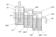
- the drain pot 20 includes a first liquid container 211, a second liquid container 212, and a third liquid container 213.
- the first liquid container 211 has a first lid 241
- the second liquid container 212 has a second lid 242
- the third liquid container 213 has a third lid 243, respectively.
- One or more (including all three) of the first lid 241, the second lid 242 and the third lid 243 may be omitted.
- a terminal end 2201 of the first drain channel 221 is arranged inside the first liquid container 211 .
- the first liquid container 211 also has a communication port 231 above the terminal end 2201 of the first drain channel 221 .
- a first connection pipe 251 extending outward from the first liquid container 211 is connected to the communication port 231 .
- a combination of the communication port 231 and the first connection pipe 251 can be regarded as the communication port in the present invention.
- a second drain channel 222 is provided so as to extend from (the first connection pipe 251 of) the communication port to the outside and downward of the first liquid container 211 .
- a terminal end 2202 of the second drain channel 222 is located inside the second liquid container 212 .
- the second liquid container 212 also has a first discharge port 232 above the terminal end 2201 of the first drain channel 221 and the terminal end 2202 of the second drain channel 222 and below the communication port 231 .
- a second connection pipe 252 extending outward from the second liquid container 212 is connected to the first discharge port 232 .
- the combination of the first outlet 232 and the second connecting pipe 252 can be regarded as the outlet in the present invention.
- a third drain flow path 223 is provided so as to extend from (the second connection pipe 252 of) the outlet to the outside and downward of the second liquid container 212 .
- a terminal end 2203 of the third drain channel 223 is located inside the third liquid container 213 . Thereby, the second liquid container 212 and the third liquid container 213 are in communication via the first discharge port 232 and the third drain passage 223 .
- the third liquid container 213 has a second outlet 233 above the terminal end 2202 of the second drain channel 222 and the terminal end 2203 of the third drain channel 223 and below the first outlet 232 . have.
- a third connection pipe 253 extending outward from the third liquid container 213 is connected to the second discharge port 233 , and a discharge pipe 29 extending downward is connected to the third connection pipe 253 .
- FIG. 1 An exploded view of the drain pot 20 is shown in FIG.
- the first liquid container 211, the second liquid container 212 and the third liquid container 213 can be separated from each other.
- a first connection pipe insertion port 262 is provided on the side surface of the second liquid container 212 , and the first connection pipe 251 is inserted into the first connection pipe insertion port 262 to connect the first liquid container 211 and the second liquid container 211 to each other.
- a liquid container 212 is integrated. After inserting the first connecting pipe 251 into the first connecting pipe insertion port 262, the second drain passage 222 is connected to the first connecting pipe 251, and then the second lid 242 is attached.
- a second connection pipe insertion port 263 is provided on the side surface of the third liquid container 213 , and the second connection pipe 252 is inserted into the second connection pipe insertion port 263 to open the second liquid container 212 . and the third liquid container 213 are integrated. After inserting the second connecting pipe 252 into the second connecting pipe insertion port 263, the third drain passage 223 is connected to the second connecting pipe 252, and then the third lid 243 is attached.
- a container set 202 combining a second liquid container 212 (including a second lid 242 and a second connecting pipe 252) and a second drain channel 222, and a third liquid container 213 (a third lid 243 and a third connecting pipe 253). ) has the same structure.
- a container set 204 combining a fourth liquid container 214 (including a fourth lid 244 and a fourth connecting pipe 254) and a fourth drain channel 224 having the same structure as the container sets 202 and 203 is a third liquid container 213.
- a drain pot with four liquid containers can be configured as shown in FIG. Drain pots with five or more liquid containers can be constructed in a similar manner.
- the container set 203 may be omitted to construct a drain pot with two liquid containers as shown in FIG. As will be described later, the greater the number of liquid containers, the higher the pressure of the gas to be analyzed that can be water-sealed.
- the number of liquid containers that the drain pot 20 has is determined according to the maximum pressure of the gas to be analyzed generated from the exhaust gas generating facility 90.
- a plurality of container sets having the same configuration as described above are prepared in advance, and the necessary number of prepared container sets are selected according to the actual maximum pressure of the gas to be analyzed. You should use only one.
- the drain pot 20 can be flexibly adjusted according to the maximum pressure of the gas to be analyzed without causing waste. Settings can be made.
- Water is stored in advance in the first liquid container 211, the second liquid container 212 and the third liquid container 213 up to the height of the communication port 231, the first discharge port 232 and the second discharge port 233, respectively.
- Drain water generated by cooling the gas to be analyzed in the cooling unit 14 flows into the first liquid container 211 through the first drain channel 221 .
- the water in the first liquid container 211 overflows and flows into the second liquid container 212 through the communication port 231 and the second drain channel 222 .
- the water in the second liquid container 212 overflows and flows into the third liquid container 213 from the first discharge port 232 through the third drain passage 223 .
- the water in the third liquid container 213 overflows and is discharged out of the drain pot 20 from the second discharge port 233 through the discharge pipe 29 .
- the discharged water is collected and treated such as removing the component of the gas to be analyzed (exhaust gas) contained in the water.
- the liquid level of the drain water in the first drain channel 221 is the first The height of the liquid surface in the liquid container 211 (that is, the height of the communication port 231) is the same, but when the gauge pressure P G of the gas to be analyzed is positive (absolute pressure is higher than the atmospheric pressure), it is pushed down more than When the gauge pressure P G of the gas to be analyzed is ⁇ h1 ⁇ g (where ⁇ is the density of the drain water and g is the gravitational acceleration), the liquid level in the first liquid container 211 and the first drain channel 221 are is ⁇ h1 (Fig. 5A).
- the height difference between the communication port 231 and the terminal end 2201 of the first drain passage 221 is ⁇ H1, then ⁇ h1 ⁇ H1.
- the gauge pressure P G of the gas to be analyzed becomes higher than ⁇ H1 ⁇ g, the liquid level in the first drain channel 221 is pushed down to the terminal end 2201 of the first drain channel 221 . Furthermore, the gas to be analyzed flows into the second drain channel 222 through the communication port 231, and the liquid level in the second drain channel 222 is equal to the liquid level in the second liquid container 212 ( That is, the height of the first discharge port 232).
- the gauge pressure P G of the gas to be analyzed is ( ⁇ H1+ ⁇ h2) ⁇ g
- the height difference between the liquid level in the second liquid container 212 and the liquid level in the second drain passage 222 is ⁇ h2. (Fig. 5B).
- the height difference between the first discharge port 232 and the terminal end 2202 of the second drain passage 222 is ⁇ H2, then ⁇ h2 ⁇ H2.
- the gauge pressure P G of the gas to be analyzed becomes higher than ( ⁇ H1+ ⁇ H2) ⁇ g, the liquid level in the second drain channel 222 is pushed down to the end 2202 of the second drain channel 222 . Furthermore, the gas to be analyzed flows into the third drain channel 223 through the first outlet 232 , and the liquid level in the third drain channel 223 is equal to the liquid level in the third liquid container 213 . height (that is, the height of the second outlet 233).
- the gauge pressure P G of the gas to be analyzed is ( ⁇ H1+ ⁇ H2+ ⁇ h3) ⁇ g
- the height difference between the liquid level in the third liquid container 213 and the liquid level in the third drain passage 223 is ⁇ h3 (Fig. 5C).
- the height difference between the second discharge port 233 and the terminal end 2203 of the third drain passage 223 is ⁇ H3, then ⁇ h3 ⁇ H3.
- the gauge pressure PG of the gas to be analyzed When the gauge pressure PG of the gas to be analyzed further increases and the liquid level in the third drain channel 223 is pushed down to the terminal end 2203 of the third drain channel 223, the gauge pressure PG at this time is ( ⁇ H1 + ⁇ H2 + ⁇ H3) ⁇ g, which is the maximum gauge pressure P Gmax that can be water-sealed with the drain pot 20 having three liquid containers shown in FIGS. 1 and 5A-C.
- the liquid container is drained.
- the height difference between the outlet and the end of the drain channel should be ( ⁇ H1 + ⁇ H2 + ⁇ H3).
- the height difference between the communicating port 231, which is the highest outlet, and the terminal end 2203 of the third drain channel 223, which is the terminal end of the lowest drain channel is ( ⁇ H1+ ⁇ H2+ ⁇ H3- ⁇ m1- ⁇ m2).
- ⁇ m1 is the difference in height between the first outlet 232 and the terminal end 2201 of the first drain channel 22
- ⁇ m2 is the difference in height between the second outlet 233 and the terminal end 2202 of the second drain channel 222.
- ⁇ m1 and ⁇ m2 are subtracted from ( ⁇ H1+ ⁇ H2+ ⁇ H3) because the first outlet 232 is above the end 2201 of the first drain passage 221 and the second outlet 233 is above the second drain passage 222. This is because they are arranged above the terminal end 2202 . Since ( ⁇ H1+ ⁇ H2+ ⁇ H3- ⁇ m1- ⁇ m2) ⁇ ( ⁇ H1+ ⁇ H2+ ⁇ H3), the overall height of drain pot 20 in this embodiment is lower than that of a drain pot having only one liquid container. can do.
- the size of the cross-sectional area of the drain pot does not affect the pressure of the gas to be analyzed that can be water-sealed. Therefore, even when a plurality of liquid containers are used as in the present embodiment, by reducing the cross-sectional area of each liquid container, the space occupied by the drain pot in the horizontal direction can be made equal to or less than the conventional one. can.
- the drain pot 20 can be made smaller than before.
- the drain pot having two liquid containers shown in FIG. 4 has a maximum gauge pressure P Gmax of ( ⁇ H1+ ⁇ H2) ⁇ g and the maximum Although it is lower than the gauge pressure, the height of the entire drain pot can be kept lower than that of the drain pot 20 concerned.
- the gauge pressure P G of the gas to be analyzed is positive, that is, the absolute pressure of the gas to be analyzed exceeds the atmospheric pressure. Water sealing by the drain pot 20 is possible even when G is negative, that is, when the absolute pressure of the gas to be analyzed is less than the atmospheric pressure.
- the liquid levels of the first drain channel 221 and the second drain channel 222 are the levels of the first liquid container 211 and the second liquid container 212, respectively. It becomes the same height as the liquid level, and the liquid level of the third drain channel 223 becomes higher than the liquid level of the third liquid container 213 .
- the liquid level of the third drain channel 223 reaches the level of the liquid level of the second liquid container 212
- the liquid level of the second drain channel 222 reaches the level of the second liquid container 212 . higher than the liquid level.
- the gauge pressure P G further decreases, the liquid level of the second drain channel 222 reaches the level of the liquid level of the first liquid container 211, and the liquid level of the first drain channel 221 reaches the level of the liquid level of the first liquid container 211. (Fig. 6).
- the present invention is not limited to the above embodiments, and various modifications are possible.
- the entire second drain channel 222 is located inside the second liquid container 212 (see FIG. 1), but even the terminal end 2202 of the second drain channel 222 is located inside the second liquid container 212.
- a portion of the second drain channel 222 may be located outside the second liquid container 212 as long as it is located inside.
- the terminal end 2203 of the third drain channel 223 is arranged inside the third liquid container 213, even if part of the third drain channel 223 is arranged outside the third liquid container 213, good.
- each container (first to third liquid containers 211 to 213) is provided with one lid (first to third lids 241 to 243), but as shown in FIG.
- a common lid 24 may be provided for a plurality of liquid containers.
- the discharge pipe 29 is connected to the third connection pipe 253 extending outward from the side surface of the third liquid container 213, but instead, the discharge pipe 29 extends upward through the bottom surface of the third liquid container 213.
- a tube 291 may be used.
- the liquid in the third liquid container 213 is discharged out of the third liquid container 213 when the liquid level in the third liquid container 213 rises to the height of the upper end 2911 of the discharge pipe 291 .
- a plurality of containers (first to third liquid containers 211 to 213) separable from each other are used, but instead, as shown in FIG. 2101 and 2102 may be divided into a plurality of partial spaces 2111, 2112 and 2113, and these plurality of partial spaces 2111 to 2113 may be used as the first liquid container, the second liquid container, etc. in the present invention, respectively.
- a gas analyzer is arranged upstream of a gas flow path through which a gas to be analyzed flows, and an analysis section provided in the gas flow path for analyzing the gas to be analyzed, and a drain pot into which the liquid generated by cooling the analysis target gas is introduced,
- the drain pot is a first liquid container that receives the end of a first drain channel through which liquid generated in the gas channel is discharged, and has a communication port vertically above the end of the first drain channel; a second drain channel extending from the communication port to the outside and vertically downward of the first liquid container; A discharge port that receives the end of the second drain channel and is provided vertically above the ends of the first drain channel and the second drain channel and below the communicating port in the vertical direction. and a second liquid container having
- the height of the entire drain pot can be kept lower than that of the conventional drain pot, and the size of the drain pot can be reduced.
- the gas analyzer according to paragraph 2 is the gas analyzer according to paragraph 1, wherein moreover, an n-th liquid container having an (n-1)-th outlet, which are (N-2) liquid containers expressed using any one natural number n from 3 to N, which is a natural number of 3 or more; , (N ⁇ 2) drain passages extending from the (n ⁇ 2)th outlet toward the outside and downward of the (n ⁇ 1)th liquid container and terminating in the nth liquid container and an n-th drain channel disposed inside the The (n-1)th outlet is above the end of the (n-1)th drain channel and the end of the nth drain channel and below the (n-2)th outlet is provided in
- (N ⁇ 2) at least one: N ⁇ 3) n-th liquid containers having the same configuration as the second liquid container are provided. Therefore, even if the pressure of the analysis target gas becomes higher, the analysis target gas can be sealed with water.
- the gas analyzer according to paragraph 3 is the gas analyzer according to paragraph 2, At least two of the combination of the second liquid container and the second drain channel and the combination of the nth liquid container and the nth drain channel have the same structure.
- the gas analyzer according to item 3 two or more sets of liquid containers and drain channels having the same structure are connected (container sets). As a result, the second liquid container and one or a plurality of n-th liquid containers, the second drain channel and one or a plurality of n-th drain channels, or a plurality of n-th liquid containers (the second liquid container is ) and a plurality of nth drain channels (not including the second drain channel).
- the number of liquid containers can be easily increased or decreased according to the maximum pressure of the gas to be analyzed. Therefore, it is possible to reduce the space occupied by the drain pot while reliably sealing the gas to be analyzed at the maximum pressure without connecting more liquid containers than necessary.
Landscapes
- Chemical & Material Sciences (AREA)
- Health & Medical Sciences (AREA)
- Life Sciences & Earth Sciences (AREA)
- Immunology (AREA)
- Analytical Chemistry (AREA)
- Biochemistry (AREA)
- General Health & Medical Sciences (AREA)
- General Physics & Mathematics (AREA)
- Physics & Mathematics (AREA)
- Pathology (AREA)
- Engineering & Computer Science (AREA)
- Combustion & Propulsion (AREA)
- Food Science & Technology (AREA)
- Medicinal Chemistry (AREA)
- Biomedical Technology (AREA)
- Molecular Biology (AREA)
- Sampling And Sample Adjustment (AREA)
Abstract
Description
該ドレンポットが、
前記ガス流路において発生した液体が排出される第1ドレン流路の終端を受け、該第1ドレン流路の終端よりも鉛直方向上方に連通口を有する第1液体容器と、
前記連通口から前記第1液体容器の外方且つ鉛直方向下方に向かうように設けられた第2ドレン流路と、
前記第2ドレン流路の終端を受け、前記第1ドレン流路の終端及び該第2ドレン流路の終端よりも鉛直方向上方であって前記連通口よりも鉛直方向下方に設けられた排出口を有する第2液体容器と
を備える。
本実施形態のガス分析装置10は、火力発電所、ごみ焼却場、工場等の排ガス発生施設90のガス排出部に取り付けられたガス採取プローブ91で採取され、パイプライン92を通じて導入された排ガスに含まれる所定の物質(例えば窒素酸化物、硫黄酸化物、一酸化炭素、二酸化炭素、酸素)の濃度を測定するために用いられる。
本実施形態のガス分析装置の動作は、ドレンポット20の動作を除いて、従来のガス分析装置の動作と同様である。以下ではドレンポット20の動作を説明する。
本発明は上記実施形態には限定されず、種々の変形が可能である。例えば、上記実施形態では第2ドレン流路222の全体が第2液体容器212の内部に配置されている(図1参照)が、第2ドレン流路222の終端2202さえ第2液体容器212の内部に配置されていれば、第2ドレン流路222の一部が第2液体容器212の外に配置されていてもよい。同様に、第3ドレン流路223の終端2203さえ第3液体容器213の内部に配置されていれば、第3ドレン流路223の一部が第3液体容器213の外に配置されていてもよい。
上述した例示的な実施形態は、以下の態様の具体例であることが当業者により理解される。
第1項に係るガス分析装置は、分析対象ガスが流れるガス流路と、該ガス流路に設けられ該分析対象ガスを分析する分析部よりも上流側に配置され、該ガス流路において該分析対象ガスを冷却することにより発生した液体が導入されるドレンポットとを備え、
該ドレンポットが、
前記ガス流路において発生した液体が排出される第1ドレン流路の終端を受け、該第1ドレン流路の終端よりも鉛直方向上方に連通口を有する第1液体容器と、
前記連通口から前記第1液体容器の外方且つ鉛直方向下方に向かうように設けられた第2ドレン流路と、
前記第2ドレン流路の終端を受け、前記第1ドレン流路の終端及び該第2ドレン流路の終端よりも鉛直方向上方であって前記連通口よりも鉛直方向下方に設けられた排出口を有する第2液体容器と
を備える。
第2項に係るガス分析装置は、第1項に係るガス分析装置において、
さらに、
3から3以上の自然数であるNまでのいずれか1つの自然数nを用いて表される(N-2)個の液体容器である、第(n-1)排出口を有する第n液体容器と、
(N-2)個のドレン流路であって、第(n-2)排出口から第(n-1)液体容器の外方且つ下方に向かうように設けられ、終端が前記第n液体容器の内部に配置された第nドレン流路と
を備え、
前記第(n-1)排出口が、前記第(n-1)ドレン流路の終端及び前記第nドレン流路の終端よりも上であって前記第(n-2)排出口よりも下に設けられている。
第3項に係るガス分析装置は、第2項に係るガス分析装置において、
前記第2液体容器と前記第2ドレン流路の組み合わせ、及び前記第n液体容器と前記第nドレン流路の組み合わせのうちの少なくとも2組が同じ構造を有する。
11…ガス取込口
12…ガス分析部
13…分析対象ガス流路
14…冷却部
15…分析対象ガス用ポンプ
20…ドレンポット
202、203、204…容器セット
21…液体容器
2101、2102…仕切り
2111、2112、2113…部分空間
211…第1液体容器
212…第2液体容器
213…第3液体容器
214…第4液体容器
2201…第1ドレン流路の終端
2202…第2ドレン流路の終端
2203…第3ドレン流路の終端
2204…第4ドレン流路の終端
221…第1ドレン流路
222…第2ドレン流路
223…第3ドレン流路
224…第4ドレン流路
231…連通口
232…第1排出口
233…第2排出口
234…第3排出口
24…蓋
241…第1蓋
242…第2蓋
243…第3蓋
244…第4蓋
251…第1接続管
252…第2接続管
253…第3接続管
254…第4接続管
262…第1接続管挿通口
263…第2接続管挿通口
29、291…排出管
2911…排出管の上端
90…排ガス発生施設
91…ガス採取プローブ
92…パイプライン
Claims (3)
- 分析対象ガスが流れるガス流路と、該ガス流路に設けられ該分析対象ガスを分析する分析部よりも上流側に配置され、該ガス流路において該分析対象ガスを冷却することにより発生した液体が導入されるドレンポットとを備え、
該ドレンポットが、
前記ガス流路において発生した液体が排出される第1ドレン流路の終端を受け、該第1ドレン流路の終端よりも鉛直方向上方に連通口を有する第1液体容器と、
前記連通口から前記第1液体容器の外方且つ鉛直方向下方に向かうように設けられた第2ドレン流路と、
前記第2ドレン流路の終端を受け、前記第1ドレン流路の終端及び該第2ドレン流路の終端よりも鉛直方向上方であって前記連通口よりも鉛直方向下方に設けられた排出口を有する第2液体容器と
を備えるガス分析装置。 - さらに、
3から3以上の自然数であるNまでのいずれか1つの自然数nを用いて表される(N-2)個の液体容器である、第(n-1)排出口を有する第n液体容器と、
(N-2)個のドレン流路であって、第(n-2)排出口から第(n-1)液体容器の外方且つ下方に向かうように設けられ、終端が前記第n液体容器の内部に配置された第nドレン流路と
を備え、
前記第(n-1)排出口が、前記第(n-1)ドレン流路の終端及び前記第nドレン流路の終端よりも上であって前記第(n-2)排出口よりも下に設けられている、
請求項1に記載のガス分析装置。 - 前記第2液体容器と前記第2ドレン流路の組み合わせ、及び前記第n液体容器と前記第nドレン流路の組み合わせのうちの少なくとも2組が同じ構造を有する、請求項2に記載のガス分析装置。
Priority Applications (4)
| Application Number | Priority Date | Filing Date | Title |
|---|---|---|---|
| US18/288,086 US20240210369A1 (en) | 2021-04-26 | 2022-01-28 | Gas analyzer |
| JP2023517049A JP7497778B2 (ja) | 2021-04-26 | 2022-01-28 | ガス分析装置 |
| CN202280024977.XA CN117083513A (zh) | 2021-04-26 | 2022-01-28 | 气体分析装置 |
| EP22795192.8A EP4332545A4 (en) | 2021-04-26 | 2022-01-28 | GAS ANALYSIS DEVICE |
Applications Claiming Priority (2)
| Application Number | Priority Date | Filing Date | Title |
|---|---|---|---|
| JP2021-074001 | 2021-04-26 | ||
| JP2021074001 | 2021-04-26 |
Publications (1)
| Publication Number | Publication Date |
|---|---|
| WO2022230269A1 true WO2022230269A1 (ja) | 2022-11-03 |
Family
ID=83848185
Family Applications (1)
| Application Number | Title | Priority Date | Filing Date |
|---|---|---|---|
| PCT/JP2022/003388 WO2022230269A1 (ja) | 2021-04-26 | 2022-01-28 | ガス分析装置 |
Country Status (5)
| Country | Link |
|---|---|
| US (1) | US20240210369A1 (ja) |
| EP (1) | EP4332545A4 (ja) |
| JP (1) | JP7497778B2 (ja) |
| CN (1) | CN117083513A (ja) |
| WO (1) | WO2022230269A1 (ja) |
Citations (5)
| Publication number | Priority date | Publication date | Assignee | Title |
|---|---|---|---|---|
| JPH0237350U (ja) * | 1988-09-03 | 1990-03-12 | ||
| JP2005195327A (ja) | 2003-12-26 | 2005-07-21 | Shimadzu Corp | ガス分析計の試料前処理装置 |
| JP2007183137A (ja) * | 2006-01-05 | 2007-07-19 | Mitsubishi Electric Corp | トリチウムモニタ |
| JP2014145625A (ja) * | 2013-01-28 | 2014-08-14 | Mitsubishi Heavy Ind Ltd | ガスサンプリングプローブ |
| JP2021015028A (ja) * | 2019-07-11 | 2021-02-12 | 株式会社島津製作所 | ガス分析装置 |
-
2022
- 2022-01-28 CN CN202280024977.XA patent/CN117083513A/zh active Pending
- 2022-01-28 EP EP22795192.8A patent/EP4332545A4/en active Pending
- 2022-01-28 US US18/288,086 patent/US20240210369A1/en active Pending
- 2022-01-28 WO PCT/JP2022/003388 patent/WO2022230269A1/ja active Application Filing
- 2022-01-28 JP JP2023517049A patent/JP7497778B2/ja active Active
Patent Citations (5)
| Publication number | Priority date | Publication date | Assignee | Title |
|---|---|---|---|---|
| JPH0237350U (ja) * | 1988-09-03 | 1990-03-12 | ||
| JP2005195327A (ja) | 2003-12-26 | 2005-07-21 | Shimadzu Corp | ガス分析計の試料前処理装置 |
| JP2007183137A (ja) * | 2006-01-05 | 2007-07-19 | Mitsubishi Electric Corp | トリチウムモニタ |
| JP2014145625A (ja) * | 2013-01-28 | 2014-08-14 | Mitsubishi Heavy Ind Ltd | ガスサンプリングプローブ |
| JP2021015028A (ja) * | 2019-07-11 | 2021-02-12 | 株式会社島津製作所 | ガス分析装置 |
Non-Patent Citations (1)
| Title |
|---|
| See also references of EP4332545A4 |
Also Published As
| Publication number | Publication date |
|---|---|
| EP4332545A4 (en) | 2024-08-21 |
| EP4332545A1 (en) | 2024-03-06 |
| JPWO2022230269A1 (ja) | 2022-11-03 |
| JP7497778B2 (ja) | 2024-06-11 |
| US20240210369A1 (en) | 2024-06-27 |
| CN117083513A (zh) | 2023-11-17 |
Similar Documents
| Publication | Publication Date | Title |
|---|---|---|
| US5837203A (en) | Device to alternately supply a fluid to an analyzer | |
| WO2022230269A1 (ja) | ガス分析装置 | |
| CN113391037B (zh) | 一种化学化工废气成分检测用留样装置及留样方法 | |
| FI112887B (fi) | Menetelmä ja laite näytteiden ottamiseksi kaasutiiviisti suljetun säiliön ilmakehästä, erityisesti ydinvoimalaitoksen reaktorivarmuussäiliöstä | |
| JPH02171634A (ja) | 化学処理過程の試料採取装置 | |
| CN107449871B (zh) | 一种用于堆肥或污水贮存气体排放监测的反应器 | |
| JP7151650B2 (ja) | ガス分析装置 | |
| KR20020040524A (ko) | 가스 분석장치 | |
| CN210775377U (zh) | 一种烟气取样分析及校准系统 | |
| JP4248470B2 (ja) | 自動分析装置 | |
| JP4804297B2 (ja) | ガスサンプリング装置およびガスサンプリング方法 | |
| KR102022344B1 (ko) | 배기가스 성분 분석 시스템 | |
| US20240142054A1 (en) | Gas management apparatus, and method for conditioning anode gas of a fuel cell | |
| CN105854517B (zh) | 一种利用氮气与抽空法结合的变压吸附脱碳装置开车前置换方法 | |
| CN207060881U (zh) | 一种分析仪试剂存储装置 | |
| US20240183761A1 (en) | Gas analysis device | |
| CN107215541A (zh) | 一种分析仪试剂仓体结构 | |
| CN215894545U (zh) | 一种带负压组件的固危废自动化验系统 | |
| JP2001193122A (ja) | 水封式ドレンタンク圧力調整装置 | |
| JPH11520A (ja) | 水分排出装置 | |
| KR102580759B1 (ko) | 가스 샘플백 세정장치 | |
| CN105854518B (zh) | 一种利用氮气与抽空结合的变压吸附脱碳装置动火前置换方法 | |
| JPH1043501A (ja) | ドレーン分離装置 | |
| WO2020084696A1 (ja) | オートサンプラ | |
| KR200195361Y1 (ko) | 고온가열로에 사용되는 배기가스 분석기의 응축수제거장치 |
Legal Events
| Date | Code | Title | Description |
|---|---|---|---|
| 121 | Ep: the epo has been informed by wipo that ep was designated in this application |
Ref document number: 22795192 Country of ref document: EP Kind code of ref document: A1 |
|
| WWE | Wipo information: entry into national phase |
Ref document number: 2023517049 Country of ref document: JP |
|
| WWE | Wipo information: entry into national phase |
Ref document number: 202280024977.X Country of ref document: CN |
|
| WWE | Wipo information: entry into national phase |
Ref document number: 18288086 Country of ref document: US |
|
| WWE | Wipo information: entry into national phase |
Ref document number: 2022795192 Country of ref document: EP |
|
| NENP | Non-entry into the national phase |
Ref country code: DE |
|
| ENP | Entry into the national phase |
Ref document number: 2022795192 Country of ref document: EP Effective date: 20231127 |