WO2022224909A1 - 車両用合わせガラス及び自動車 - Google Patents
車両用合わせガラス及び自動車 Download PDFInfo
- Publication number
- WO2022224909A1 WO2022224909A1 PCT/JP2022/017958 JP2022017958W WO2022224909A1 WO 2022224909 A1 WO2022224909 A1 WO 2022224909A1 JP 2022017958 W JP2022017958 W JP 2022017958W WO 2022224909 A1 WO2022224909 A1 WO 2022224909A1
- Authority
- WO
- WIPO (PCT)
- Prior art keywords
- vehicle
- glass plate
- glass
- strength
- laminated glass
- Prior art date
- Legal status (The legal status is an assumption and is not a legal conclusion. Google has not performed a legal analysis and makes no representation as to the accuracy of the status listed.)
- Ceased
Links
Images






Classifications
-
- B—PERFORMING OPERATIONS; TRANSPORTING
- B32—LAYERED PRODUCTS
- B32B—LAYERED PRODUCTS, i.e. PRODUCTS BUILT-UP OF STRATA OF FLAT OR NON-FLAT, e.g. CELLULAR OR HONEYCOMB, FORM
- B32B17/00—Layered products essentially comprising sheet glass, or glass, slag, or like fibres
-
- B—PERFORMING OPERATIONS; TRANSPORTING
- B60—VEHICLES IN GENERAL
- B60J—WINDOWS, WINDSCREENS, NON-FIXED ROOFS, DOORS, OR SIMILAR DEVICES FOR VEHICLES; REMOVABLE EXTERNAL PROTECTIVE COVERINGS SPECIALLY ADAPTED FOR VEHICLES
- B60J1/00—Windows; Windscreens; Accessories therefor
Definitions
- the present invention relates to laminated glass for vehicles and automobiles.
- Patent Document 1 includes a molding that connects the rear end portion of the cowl louver and the front end portion of the windshield glass, and a plate-shaped core metal is embedded inside the molding.
- a glass connecting structure for a vehicle in which a fragile portion is provided in the core metal.
- this vehicle glass connection structure when a pedestrian collides with the vehicle from the front and a downward impact is applied to the cowl louver and the surroundings of the windshield glass, the cowl louver and the windshield that are connected are separated. By being separated, the pedestrian's body protection performance is secured.
- a glass plate originally has an in-plane strength distribution, and the strength of a glass plate is usually determined probabilistically by factors such as the safety factor and breakage probability. Therefore, even if the strength of the entire window glass is appropriate, there may be localized regions with excessively high strength (hereinafter also referred to as high-strength regions) in the plane of the window glass, and such high-strength regions In the event that a pedestrian, etc., collides with a vehicle, the window glass cannot easily break, so the window glass cannot absorb the impact, and the interlayer film cannot perform its function, which may cause injury to the human body. can be large.
- An object of one aspect of the present invention is to provide a laminated glass for a vehicle that has the necessary toughness as a window glass for a vehicle and that enhances the body protection performance against pedestrians and the like in the event of a collision.
- One aspect of the laminated glass for a vehicle according to the present invention includes a first glass plate arranged on the outside of the vehicle, a second glass plate arranged on the inside of the vehicle, and the first glass plate and the second glass plate. and an intermediate film to be bonded, wherein a strength leveling portion is formed by subjecting a part or the entire main surface of at least one of the first glass plate and the second glass plate to a scratching treatment, and the strength The surface roughness Ra of the leveled portion is 0.1 nm to 8.0 nm.
- One aspect of the laminated glass for vehicles according to the present invention has the necessary robustness as a window glass for vehicles, and also enhances the body protection performance against pedestrians and the like in the event of a collision.
- FIG. 1 is a front view of an automobile provided with a laminated glass for vehicles according to an embodiment of the present invention
- FIG. FIG. 2 is a front view of the laminated glass for a vehicle shown in FIG. 1
- FIG. 2 is a partial cross-sectional view of the laminated glass for a vehicle shown in FIG. 1
- 1 is an exploded perspective view of a laminated glass for a vehicle
- FIG. FIG. 4 is a partially enlarged view of the second surface of the vehicle-exterior glass plate in a state in which the vehicle-exterior glass plate and the intermediate film are separated;
- FIG. 3 is a partially enlarged cross-sectional view of the vehicle-exterior glass plate and the intermediate film when viewed in a state in which the vehicle-exterior glass plate and the interlayer are separated;
- FIG. 3 is a front view showing an example of another configuration of the laminated glass for vehicles.
- FIG. 8 is an exploded perspective view of the laminated glass for a vehicle shown in FIG. 7;
- 1 is a flow chart showing an example of a method for manufacturing laminated glass for vehicles. It is a flowchart which shows an example of a flat glass plate preparation process (step S11). It is a figure which shows typically a roller conveyor as an example of a conveying means.
- FIG. 4 is a diagram illustrating an example of a conveying roller; It is a figure explaining another example of a conveyance roller. It is a figure explaining an example of the wounding function of a conveying means.
- FIG. 10 is a diagram for explaining another example of the scratching function of the conveying means;
- Laminated glass for vehicles includes window glass for automobiles such as windshield, rear glass, side glass, roof glass and quarter glass, window glass for vehicles such as trains and locomotives, and windows for construction vehicles such as bulldozers. Glass, window glass for aircraft such as airplanes, window glass for other special vehicles, etc. In this embodiment, the case where the laminated glass for vehicles is used for the windshield of an automobile will be described.
- FIG. 1 is a front view of an automobile provided with laminated glass for vehicles according to this embodiment. As shown in FIG. 1 , a laminated glass for vehicle 1 according to this embodiment is used as a windshield of an automobile 100 .
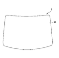
- FIG. 2 is a plan view of the laminated glass for vehicle 1 shown in FIG. 1
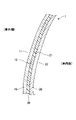
- FIG. 3 is a partial sectional view of the laminated glass for vehicle 1 shown in FIG. 1
- FIG. 4 is an exploded view of the laminated glass for vehicle 1.
- FIG. 2 to 4 one of the main surfaces of the laminated glass 1 for a vehicle is the outside of the vehicle, and the other is the inside of the vehicle.
- the front side is the outside of the vehicle, and the back side is the inside of the vehicle.
- the longitudinal direction of the laminated glass 1 for a vehicle corresponds to, for example, the width direction of the vehicle, but may correspond to the vertical direction of the vehicle.
- the left side is the outside of the vehicle, and the right side is the inside of the vehicle.
- the upper left side is the outside glass, the center is the intermediate film, and the lower right side is the inside glass.
- the laminated glass for vehicles 1 is formed in a substantially trapezoidal shape when viewed from the front, and has rounded corners. Further, as shown in FIG. 3, the laminated glass for vehicle 1 has a curved surface whose main surface is curved convexly toward the outside of the vehicle, and has a predetermined curvature.
- the laminated glass for vehicle 1 may be curved as a whole or partially so as to be convex toward the outside of the vehicle.
- the vehicle-exterior glass plate 10 and the vehicle-interior glass plate 20 can be processed and bent to desired predetermined curvatures in one direction or two directions, respectively, by a bending process described later.
- the laminated glass 1 for a vehicle includes a vehicle-exterior glass plate 10 as a first glass plate, a vehicle-interior glass plate 20 as a second glass plate, and an intermediate film 30. It is joined to the vehicle-interior glass plate 20 via an intermediate film 30 .
- the vehicle-exterior glass plate 10 has a first surface 11 that is a vehicle-exterior surface (main surface) and a second surface 12 that is a vehicle-interior surface (main surface). It has a third surface 21 that is an outer surface (main surface) and a fourth surface 22 that is an inner surface (main surface).
- Inorganic glass is preferable as a material for forming the vehicle-exterior glass plate 10 and the vehicle-interior glass plate 20 (hereinafter collectively referred to simply as the glass plate).
- examples of inorganic glass include soda lime silicate glass, aluminosilicate glass, borate glass, lithium aluminosilicate glass, and borosilicate glass.
- the method of forming the glass plate made of inorganic glass is not particularly limited, but the glass plate is preferably formed by, for example, the float method.
- the glass plate may be untempered glass (raw glass). Untempered glass is glass obtained by molding molten glass into a plate shape and then slowly cooling it, and is glass that has not undergone tempering treatment such as air-cooling tempering treatment or chemical tempering treatment. By using untempered glass, even if the glass breaks due to an impact, it is difficult for a net-like or spider-web-like crack to occur, and the visibility of the occupant can be ensured even in the event of an accident.
- the thickness of the vehicle-exterior glass plate 10 and the vehicle-interior glass plate 20 may be the same or may be different.
- the thickness of the vehicle-exterior glass plate 10 may be 1.1 mm to 3.5 mm. Further, the thickness of the vehicle-inside glass plate 20 may be 0.5 mm to 2.5 mm.
- the thickness of the entire laminated glass 1 for vehicles can be 2.3 mm to 8.0 mm.
- the configurations of the vehicle-exterior glass plate 10 and the vehicle-interior glass plate 20 may be the same or may be different.
- the laminated glass 1 for a vehicle includes a second surface 12 of the vehicle-exterior glass plate 10 and a fourth surface 22 of the vehicle-interior glass plate 20, which are subjected to a scratch treatment to level the strength. It has a processing unit 40 .
- the strength leveling processing portion 40 includes a strength leveling processing portion 40A formed on the entire second surface 12 of the vehicle-exterior glass plate 10 and a strength leveling processing unit 40A formed on the entire fourth surface 22 of the vehicle-interior glass plate 20. and a conversion processing unit 40B.
- FIG. 5 is a partially enlarged view of the second surface 12 of the vehicle-exterior glass plate 10 with the vehicle-exterior glass plate 10 and the intermediate film 30 separated
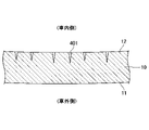
- FIG. FIG. 3 is a partially enlarged cross-sectional view of the vehicle-exterior glass plate 10 viewed in a state in which it is separated from the intermediate film 30
- the second surface 12 of the vehicle-exterior glass plate 10 faces upward.
- the strength leveling processing unit 40A is applied to the second surface 12 of the vehicle-exterior glass plate 10 in a region where fine linear cracks (hereinafter simply referred to as "cracks") 401 are formed. be.
- the crack 401 is formed on the entire second surface 12 because the strength leveling portion 40A is provided on the entire surface of the second surface 12 .
- the cracks 401 may be groove-shaped.
- the crack 401 may be formed in a substantially triangular shape in a cross-sectional view of the vehicle-exterior glass plate 10, and may be formed so that the groove width decreases in the depth direction. It may be formed to have almost the same width as the second surface 12 of the outer glass plate 10 at a predetermined depth position.
- the strength leveling processing section 40B is the same as the strength leveling processing section 40A except that it is formed on the surface of the fourth surface 22 of the vehicle interior side glass plate 20, so details thereof will be omitted.
- Cracks 401 are formed on the entire surfaces of the second surface 12 and the fourth surface 22 by providing the strength leveling portion 40 on the entire surfaces of the second surface 12 and the fourth surface 22 .
- the in-plane strength of the vehicle-exterior glass plate 10 and the vehicle-interior glass plate 20 can be made uniform, and the strength required for vehicle window glass can be maintained.
- the direction of the cracks 401 of the strength leveling processor 40A is not particularly limited, but it is preferable that the cracks 401 are formed randomly when viewed from the front of the second surface 12 .
- the in-plane strength of the vehicle-exterior glass plate 10 and the vehicle-interior glass plate 20 is more likely to be uniformly reduced in all directions in the plane direction.
- the surface roughness Ra of the intensity leveling treatment portion 40 is 0.1 nm to 8.0 nm, preferably 0.5 nm to 5.0 nm, more preferably 0.7 nm to 2.0 nm. If the surface roughness Ra is 0.1 nm to 8.0 nm, it is used as an index for determining whether the intensity leveling processed portion 40 is formed on the second surface 12 .
- the surface roughness Ra of the intensity leveling processing unit 40 is measured using a general measuring method such as a method using a scanning probe microscope such as a scanning tunneling microscope (STM) or an atomic force microscope (AFM). good.
- a scanning probe microscope such as a scanning tunneling microscope (STM) or an atomic force microscope (AFM). good.
- the surface roughness Rz of the intensity leveling processing unit 40 measured by AFM is preferably 0.3 nm to 30.0 nm, more preferably 0.6 nm to 15.0 nm, and still more preferably 1.2 nm. ⁇ 7.5 nm.
- the surface roughness Rz of the intensity leveling processing unit 40 may be measured using a general measurement method such as a method using a scanning probe microscope such as STM or AFM.
- the intensity leveling processing section 40 may have only the intensity leveling processing section 40A or the intensity leveling processing section 40B. In this case, when a pedestrian or the like collides with the windshield of the automobile from the outside of the vehicle, the second surface 12 is more affected by the impact than the fourth surface 22. Therefore, the intensity leveling processing unit 40 , and an intensity leveling processing unit 40A.
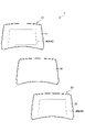
- FIG. 7 is a front view showing another example of the configuration of the laminated glass for vehicles
- FIG. 8 is an exploded perspective view of the laminated glass for vehicles shown in FIG. 7 and 8, the intensity leveling processing unit 40 is indicated by broken lines.
- the intensity leveling processing section 40 may include the intensity leveling processing section 40A on a part of the second surface 12, or the intensity leveling processing section 40B on a part of the fourth surface 22. may be set to When the intensity leveling processing unit 40 has the intensity leveling processing unit 40A and the intensity leveling processing unit 40B on part of the second surface 12 and the fourth surface 22, as shown in FIG. and the intensity leveling processing unit 40B may be provided at substantially the same position when viewed from the front.
- the intensity leveling processing section 40A and the intensity leveling processing section 40B are preferably provided so as to overlap each other when viewed from the front. may be provided so as to be inside or outside the
- the ratio of the surface roughness Ra of the strength leveling processing unit 40 to the surface roughness Ra of the second surface 12 and the fourth surface 22 other than the strength leveling processing unit 40 is preferably 9.0 or less, more preferably 5.0 or less, More preferably, it is 2.0 or less.
- the strength leveling processing unit 40 performs a scratching process on the second surface 12 of the vehicle-exterior glass plate 10 and the fourth surface 22 of the vehicle-interior glass plate 20 by a method for manufacturing laminated glass for vehicles, which will be described later. It is a region containing a crack 401 formed by . That is, as will be described later, the strength leveling processing unit 40 carries two flat glass plates by a carrying means, and at the same time, the surfaces of the glass plates facing the carrying means are scratched by the carrying means. It is formed by forming a plurality of cracks 401 .
- the intermediate film 30 is arranged between the vehicle-exterior glass plate 10 and the vehicle-interior glass plate 20 .
- the intermediate film 30 joins the vehicle-exterior glass plate 10 and the vehicle-interior glass plate 20 .
- the material of the intermediate film 30 is not particularly limited, it is preferably a thermoplastic resin.
- Thermoplastic resins include plasticized polyvinyl acetal resins, plasticized polyvinyl chloride resins, saturated polyester resins, plasticized saturated polyester resins, polyurethane resins, plasticized polyurethane resins, and ethylene-vinyl acetate copolymers.
- thermoplastic resins such as resins, ethylene-ethyl acrylate copolymer resins, cycloolefin polymer resins, and ionomer resins can be used.
- a resin composition containing a hydrogenated modified block copolymer described in Japanese Patent No. 6065221 can also be preferably used.
- plasticized polyvinyl acetal resin is excellent in the balance of performance such as transparency, weather resistance, strength, adhesive strength, penetration resistance, impact energy absorption, moisture resistance, heat insulation, and sound insulation. is preferably used. You may use said thermoplastic resin individually or in combination of 2 or more types.
- “Plasticization” in the above-mentioned plasticized polyvinyl acetal resin means plasticization by addition of a plasticizer. The same applies to other plasticizing resins.
- the intermediate film 30 may be a plasticizer-free resin such as an ethylene-vinyl acetate copolymer resin.
- polyvinyl acetal-based resin examples include a polyvinyl formal resin obtained by reacting polyvinyl alcohol (PVA) and formaldehyde, a narrowly defined polyvinyl acetal-based resin obtained by reacting PVA and acetaldehyde, and PVA and n-butyraldehyde.
- Polyvinyl butyral resin (PVB) obtained by reacting is mentioned.
- PVB is a suitable material because it has a good balance of properties such as transparency, weather resistance, strength, adhesion, penetration resistance, impact energy absorption, moisture resistance, heat insulation, and sound insulation.
- a shielding layer may be provided on the periphery of the laminated glass for vehicle 1 to protect the sealant or the like that adheres and holds the laminated glass for vehicle 1 to the vehicle body.
- the shielding layer can be formed, for example, by applying a low-brightness color ceramic color paste such as black, gray, or dark brown containing a fusible glass frit containing a black pigment, and firing the paste.
- the shielding layer is formed on one or more of the second surface 12, the third surface 21, and the fourth surface 22 (FIG. 2) of the laminated glass for vehicles 1, preferably on the periphery of at least one of the second surface 12 and the fourth surface 22. may be formed.
- the shielding layer may be provided from 10 mm to 300 mm from the peripheral edge of the glass plate.
- the average value of the top 20% of the breaking stress distribution measured by a method according to ISO1288-5 (2016) by applying a load from the outside of the vehicle in the transmission region is preferably 500 MPa or less. may be 450 MPa or less.
- the transmissive region refers to a portion of the laminated glass for vehicles excluding the shielding layer formed on the laminated glass for vehicles.
- FIG. 9 is a flow chart showing an example of a method for manufacturing a laminated glass for vehicles according to this embodiment.
- the method for manufacturing a laminated glass for a vehicle according to the present embodiment includes a flat glass plate preparation step (step S11) for preparing a flat glass plate, and bending the prepared flat glass plate. and a bonding step (step S13) of bonding the two bent glass plates together.
- the flat glass plate preparation step (step S11) includes the following steps. That is, in the flat glass plate preparation step (step S11), as shown in FIG. 10, a long strip glass plate is manufactured by a float method, a roll-out method, or the like (step for manufacturing a strip glass plate: step S111), The strip glass plate is slowly cooled (slow cooling step: step S112).
- a raw plate is cut out from the strip glass plate (cutting step: step S113), the raw plate is cut into a desired outer shape (cutting step: step S114), and chamfered ( Chamfering step: step S115), washing (washing step: step S116), and printing a shielding layer (printing step: step S117).
- the flat glass plate preparation step (step S11) is performed by subjecting one main surface of the flat glass plate to a scratching treatment between the slow cooling step (step S112) and the printing step (step S117). to form microcracks (scratch treatment step).
- step S111 The order of these steps (step S111) to (step S117) may be partially interchanged. Also, some of these steps (step S111) to (step S117) may be changed or omitted, and other steps may be performed between some of the steps (step S111) to (step S117). may be included in For example, one or more additional cleaning steps other than the cleaning step (step S116) may be added at any timing from the slow cooling step (step S112) to the chamfering step (step S115).
- step S112 A description will be given of the scratch treatment process performed between the slow cooling process (step S112) and the printing process (step S117) in the method for manufacturing laminated glass for vehicles.
- HIC Head Injury Criterion
- the area of excessively high strength (high-strength area) in laminated glass for vehicles should be reduced or eliminated, and the strength over the surface direction should be reduced. It is important that the distribution is suppressed (narrow intensity distribution). That is, in order to improve the performance of protecting the body of pedestrians and the like in the event of a collision, it is important that the in-plane strength is made uniform or leveled as much as possible.
- the laminated glass for vehicles 1 is manufactured including a step of scratching the surface of the planar glass plate before the bending step (step S12).
- the scratches may be randomly formed on the surface of the glass plate, as shown in FIG. Moreover, as shown in FIG. 6, the scratch may be formed in a groove shape in a cross-sectional view of the glass plate.
- damage is a process of forming fine cracks (also called microcracks, invisible fine cracks of micrometer order or smaller) on the surface of a glass plate.
- fine cracks also called microcracks, invisible fine cracks of micrometer order or smaller
- the strength of the glass plate and the laminated glass obtained by using the glass plate can be made uniform or leveled over the surface direction.
- Fine cracks are originally present on the surface of a glass plate after production, and it is said that the uneven distribution of these fine cracks is the cause of variations in the strength of glass for automobile windows.
- the second surface 12 of the vehicle-exterior glass plate 10 and the fourth surface 22 of the vehicle-interior glass plate 20 are newly introduced with fine cracks 401 by scratching, thereby increasing the strength. It is thought that the strength of the excessively high region (high strength region) can be reduced. On the other hand, this damage does not further reduce the strength of the relatively low strength region (low strength region), or hardly reduces it. Therefore, by performing a scratching treatment at the time of manufacturing the vehicle laminated glass 1, the in-plane strength of the vehicle-exterior glass plate 10 and the vehicle-interior glass plate 20, or the vehicle laminated glass 1 can be made uniform, and the strength of the vehicle laminated glass 1 can be improved. The strength required for window glass is also maintained. As a result, the laminated glass 1 for a vehicle has the necessary robustness as a window glass for a vehicle, and also has performance capable of ensuring the physical safety of pedestrians and the like even when they collide.
- the above-described scratching treatment is performed on at least one of the two flat plate glasses that form the vehicle laminated glass 1, on the surface that will be on the inside of the vehicle when attached to the vehicle.
- the impact of the collision spreads from the first surface 11 of the vehicle-exterior glass plate 10, which is the outermost surface, to the first surface 11 of the vehicle-interior glass plate 20, which is the innermost surface. It is sequentially transmitted to the four surfaces 22 (FIG. 2).
- the vehicle-exterior glass plate 10 a compressive stress against a compressive force that shrinks the area is generated on the first surface 11, and a tensile stress against a tensile force that expands the area is generated on the second surface 12. Therefore, the vehicle-exterior glass plate 10 tends to crack from the vehicle-interior second surface 12 . Therefore, it is preferable that the second surface 12 is appropriately crackable at the time of collision, that is, there are no or few high-strength areas where the strength is locally excessively high on the second surface 12 .
- the third surface 21 focuses on the interior glass plate 20, the third surface 21 generates a compressive stress corresponding to the compressive force that shrinks the area, and the fourth surface 22 generates a tensile stress corresponding to the tensile force that expands the area.
- the glass plate 20 inside the vehicle tends to crack from the fourth surface 22 on the inside of the vehicle. Therefore, it is preferable that the fourth surface 22 is appropriately crackable at the time of collision, that is, there is no or little high-strength region where the strength is locally excessively high on the fourth surface 22 .
- At least the second surface 12 of the vehicle-interior glass plate 10 and the fourth surface 22 of the vehicle-interior glass plate 20 are used from the viewpoint of protecting the body of pedestrians and the like in the event of a collision.
- One side is damaged.
- the glass plate to which the scratching treatment is applied is in a flat plate-like state before being bent. That is, the scratching process is performed not on the curved surface of the glass plate but on the flat surface of the glass plate.
- the scratching treatment is preferably performed over the entire surface of the glass plate in order to make the in-plane strength more uniform. It is necessary to change the facing direction of the scratching means and the scratching means itself according to the curve of , and the process tends to be complicated. Further, in the present embodiment, the scratching treatment is applied to at least one of the second surface 12 and the fourth surface 22, which are the surfaces of the laminated glass 1 for vehicles, which are the inner surfaces of the vehicle. (Fig. 2).
- the scratching process is performed by the conveying means in the flat glass plate preparation step (step S11).
- the conveying means is means for moving the strip glass plate or the glass plate in a predetermined direction and conveying it from one processing device to the next processing device in the flat glass plate preparation step (step S11).
- the conveying means may be continuous means throughout the flat glass plate preparation step (step S11), or may be discontinuous. It is preferable that the conveying means supports and conveys the belt-shaped glass plate or the glass plate from below.
- Specific examples of conveying means include roller conveyors and belt conveyors. Among these, it is preferable to use a roller conveyor in at least a part of the production line of the flat glass plate preparation step (p) because the conveying speed can be easily controlled.
- a roller conveyor may convey the glass sheet at a speed of 0.01 m/s to 2.0 m/s.
- FIG. 11 schematically shows a roller conveyor 50 as an example of conveying means.
- the roller conveyor 50 extends in a direction orthogonal to the transport direction Dt and includes a plurality of transport rollers 51, 51, .
- the flat glass plates G, G, . . . are placed on and supported by the transport rollers 51, 51, . At least part of the plurality of conveying rollers 51, 51, .
- at least some of the conveying rollers 51, 51, . is shown.
- the radius of the conveying roller may be 10 mm to 20 cm, depending on the size, thickness, etc. of the glass plate to be conveyed. It is preferable that at least the material of the surface of the conveying roller is made of a rubber-like material (a material such as rubber, which has high frictional resistance against glass and has elasticity). For example, a sheet-like rubber-like body continuous in the axial direction Da of the conveying roller (the direction perpendicular to the conveying direction Dt in the roller conveyor of FIG.
- the entire conveying roller may be made of a rubber-like material.
- FIGS. 12 and 13 show an example of a conveying roller 51 in which a rubber-like body is arranged on the peripheral surface of the shaft.
- the diameter D and the radius r of the transport roller 51 respectively refer to the diameter and radius of the configuration including the rubber-like body.
- a string-like rubber-like body 511 having a substantially circular cross section is spirally wound around a shaft body 515 .
- the rubber-like body 511 is preferably wound with a gap d of 500 mm or less when viewed in the axial direction Da (direction perpendicular to the transport direction Dt).
- the length (width) w of the rubber-like body 511 in the axial direction Da may be 2 mm to 50 mm.
- the width w may be the length (width) in the axial direction Da in which the rubber-like body continuously contacts the glass plate while the flat glass plate is being conveyed.
- the distance d between the plurality of rubber-like bodies 511 in the axial direction Da may be 500 mm or less.
- the maximum value of the length (width) w in the axial direction Da of one rubber-like body 511 may be the same as the length of the shaft. It's okay.
- the conveying roller 51 shown in FIG. 6 it is preferable that there are a plurality of conveying rollers having such a scratching function. Further, if the positions of the rubber-like members 511, 511, .
- adjacent conveying rollers may be in contact with each other or may be separated from each other, and when the conveying rollers are separated from each other, the interval between the conveying rollers may be 50 cm or less.
- the angular velocity of a conveying roller used as a normal conveying means is 0.2 rad/s to 40 rad/s, depending on the diameter of the conveying roller and the state of the glass plate to be conveyed.
- the scratching treatment in the method for manufacturing laminated glass for vehicles according to the present embodiment is performed in the flat glass plate preparation step (step S11), but more specifically, after the slow cooling step (step S112). Yes, and may be performed at any timing before the printing process (step S117). That is, if the surface of the flat glass plate facing the conveying means is to be scratched by the conveying means, after the slow cooling step (step S112), the glass plate is cut out (step S113), and then cut into a desired shape. It may be performed in one or more of the cutting step (step S114), the chamfering step (step S115) and the cleaning step (step S116) (FIG. 10), or before or after one or more of these steps.
- the scratching process is performed after the cleaning process (step S116), it is preferable to perform the scratching process before the printing process (step S117).
- the shielding layer is heated for baking, and cooled after baking.
- the scratching process can be performed while the glass plate is being conveyed between any of the slow cooling process (step S112) and the cleaning process (step S116) and the process following that process.
- the scratching process may be performed at two or more timings after the end of the slow cooling process (step S112) and before the start of the bending process (step S12).
- the injury function of the roller conveyor is, for example, the rotational speed, diameter, and height of at least one of the plurality of conveying rollers 51, 51, . may be obtained by making one or more of the transport rollers adjacent to the at least one transport roller different.
- FIG. 14 schematically shows a cross section of an example of a roller conveyor 50 having a scratching function.
- the angular velocity or rotational speed (driving speed) ⁇ ′ of one conveying roller 51a is reduced by 0.3% to 5% relative to the angular velocity ⁇ of the conveying roller 51 adjacent to the one conveying roller. , preferably adjusted to be larger or smaller by 0.5% to 2%. That is, the value of (
- the angular velocity of one conveying roller is reduced by the ratio within the above range with respect to the angular velocity of the conveying roller adjacent to the upstream side of the one conveying roller.
- the conveying rollers 51a having different angular velocities may be a plurality of continuously arranged or discontinuous conveying rollers. Therefore, the angular velocities of one or more transport rollers are set to be within the above range with respect to the angular velocities of both the transport rollers adjacent to the upstream side and/or the transport rollers adjacent to the downstream side of the one or more transport rollers. It can be adjusted to be proportionally larger or smaller.
- FIG. 15 schematically shows another example of a roller conveyor equipped with a scratching function.
- the radius r' of one transport roller 51b is larger than the diameter r of the transport roller 51 adjacent to the one transport roller 51b by 5 ⁇ m to 2 mm, preferably by 10 ⁇ m to 1 mm. can be adjusted accordingly. That is, r'-r can be adjusted to a value within the above range.
- the radii r and r' of the conveying rollers are radii including the rubber-like body as described above when the rubber-like body is disposed around the shaft (Figs. 12 and 12). 13).
- the radius of one transport roller it is possible to set the radius of one transport roller to be larger than the radius of both the downstream transport roller and the upstream transport roller of the one transport roller by a predetermined value.
- the transport rollers 51b having different radii may be a plurality of transport rollers arranged continuously or discontinuously. As shown in FIG. 15, the conveying rollers 51b having different radii protrude further toward the glass plate than the adjacent conveying rollers by ⁇ r. More of the own weight of the plate is received by the transport roller 51b than the other adjacent transport rollers 51, 51, . . . Can injure.
- a similar effect is obtained by increasing the height (position) of the transport roller(s) by 5 ⁇ m to 2 mm, preferably 10 ⁇ m, above the height of the transport roller(s) without changing the radius of the transport roller. It can also be obtained by adjusting it to be larger by ⁇ 1 mm.
- the roughening of the surface of the conveying roller can be obtained, for example, by covering it with a covering sheet having a rough surface. can be done.
- the roller conveyor (conveying means) with a scratching function can also be obtained by roughening at least one surface of a plurality of conveying rollers, in other words, forming unevenness on at least one surface. be done.
- the degree of surface roughening depends on the type of glass plate to be scratched, the size and shape of the band-shaped glass plate or the glass plate, etc., but the surface roughness Ra of the conveying roller can be 0.02 ⁇ m to 100 ⁇ m.
- the roughening of the surface of the transport roller can be obtained, for example, by rubbing the surface of the transport roller entirely or partially with an abrasive, abrasive paper, or the like. Alternatively, it is also possible by adhering and fixing fine powder on the surface of the conveying roller. Alternatively, the rubber-like material on the surface that is normally used can be replaced with a rubber-like material kneaded with powder for the purpose of scratching. Furthermore, it is also possible to cover all or part of the surface of the conveying roller with a covering sheet having a rough surface.
- the coating sheet is a sheet made of resin, rubber, fiber-containing material (woven fabric, knitted fabric, non-woven fabric, paper, etc.), etc., and has a rough surface, or a surface of such a sheet on which fine powder is attached. It may be one that has been fixed by letting it.
- the sheet having the rough surface is provided over a range corresponding to the entire width of the band-shaped glass plate or glass plate to be scratched on the conveying roller. In that case, it can be provided over the entire surface of the transport roller, that is, over the entire or substantially the entire axial direction of the transport roller. Also, the sheet having the rough surface does not have to be provided over the entire circumferential direction of the conveying roller.
- the material (rubber-like material) attached to the conveying roller such as rubber, is used to prevent slipping.
- the material (rubber-like material) attached to the conveying roller such as rubber
- the material (rubber-like material) attached to the conveying roller is used to prevent slipping.
- the material (rubber-like material) attached to the conveying roller such as rubber
- the material (rubber-like material) attached to the conveying roller is used to prevent slipping.
- the material (rubber-like material) attached to the conveying roller such as rubber
- the material (rubber-like material) attached to the conveying roller such as rubber, is used to prevent slipping.
- the glass with a rubber-like material it is possible to obtain the contacting surface of the rubber-like body by covering it with a coating sheet having a rough surface.
- the coating sheet is a sheet made of resin, rubber, fiber-containing material (woven fabric, knitted fabric, non-woven fabric, paper, etc.), etc., and has a rough surface, or a surface of such a sheet on which fine powder is attached. It may be one that has been fixed by letting it.
- the scratching by the conveying means described above is a process performed so as to make the in-plane strength of the glass plate more uniform. Therefore, the scratching treatment is a treatment for suppressing the in-plane strength distribution or variation of the flat glass plate. That is, when the distribution of the strength values (breaking stress or bending strength) measured in a plurality of regions in the plane of the glass plate is determined, the adjustment is performed so as to narrow the distribution.
- the scratching performed in the method for manufacturing the laminated glass for vehicles according to the present embodiment it is possible to maintain a strength that satisfies sufficient robustness as a window glass.
- the surface of a glass plate is divided into a plurality of regions, the strength of each region is measured, and the frequency distribution of strength is obtained, the distribution region with high strength shifts in the direction of low strength due to the scratching treatment. and the position of the distribution region with low intensity does not change much.
- the scratching by the conveying means described above can also be performed by interposing water or an aqueous solution between the surface of the glass plate facing the conveying means and the conveying means. Water or an aqueous solution can be applied, sprinkled or sprayed onto the surface of the carrier prior to abrading.
- the washing liquid including the detergent liquid and the rinsing liquid
- No additional water or aqueous solution is required as it is interposed between the means.
- step S12 the bending process (step S12) is performed after the flat glass plate preparation process (step S11).
- the flat glass plate is curved by heating to near or above the softening point.
- Bending may be gravity bending in which the glass plate is placed on a ring mold and bent by the weight of the glass plate in a heating furnace. ), or a combination thereof.
- the bending may be performed by bending the glass plate alone, or by stacking the two glass plates bonded together in the bonding step (step S13) and then bending the glass plate in the stacked state. In either case, the glass plate is curved so as to be convex downward (downward in the vertical direction).
- the bending process (step S12) is performed after the flat glass plate preparation process (step S11). In the bending step (step S12), as described above, at least one of the two glass plates is scratched on the conveying means facing surface (downward surface).
- the surfaces (the second surface 12 and/or the fourth surface 22) on the inside of the vehicle, which are concave surfaces, are scratched. Therefore, in the case of molding in a state of being placed horizontally, in the present embodiment, in the flat glass plate preparation step (step S11), after the scratching treatment is performed by the conveying means, the scratched glass It is preferable to flip the plate over. As a result, the scratched surface faces upward in the vertical direction, and if it is sent to the bending step (step S12) while still facing upward in the vertical direction and is bent, the glass plate with the concavely scratched surface is obtained. can get.
- the heating temperature of the glass during bending may be about 550°C to 700°C.
- the bending step (step S12) may be a single-bend bending process in which a flat glass plate is bent only in one direction, for example, only in the longitudinal direction or the vertical direction of the automobile when it is attached to the opening of the automobile. Alternatively, it may be formed by bending in the front-rear direction and in the vertical direction.
- the curvature radius of the glass plate obtained by the bending step (step S12) may be 1000 mm to 10000 mm. Further, the radius of curvature of the vehicle-exterior glass plate 10 and the vehicle-interior glass plate 20 in the laminated glass for vehicle 1 may be the same or may be different.
- step S13 a bonding step (step S13) is performed.
- the two glass sheets that have been bent in the bending step (step S12) are bonded via an intermediate film to obtain laminated glass.
- the surface of the glass plate which was the surface facing the conveying means when it was scratched in the flat glass plate preparation step (step S11), is changed to the inside of the vehicle when it is attached to the vehicle.
- the two glass plates are joined together by stacking them so that they are flat.
- a laminated body is formed by sandwiching the above-described resin-made intermediate film between two glass plates. and a step of applying heat and pressure in an autoclave for final pressure bonding.
- the preliminary press-bonding step may be a rubber channel method or a nip roller method.
- the vehicle laminated glass 1 includes the vehicle-exterior glass plate 10, the vehicle-interior glass plate 20, and the intermediate film 30.
- An intensity-leveling processed portion 40 is formed on the fourth surface 22 of the inner glass plate 20, and the surface roughness Ra of the intensity-leveling processed portion 40 is 0.1 nm to 8.0 nm. If the surface roughness Ra is 0.1 nm to 8.0 nm, it can be determined that the cracks 401 included in the intensity leveling processed portion 40 are formed on the second surface 12 and the fourth surface 22 .
- the strength leveling processing unit 40 can reduce the strength of the vehicle-exterior glass plate 10 and the vehicle-interior glass plate 20 substantially uniformly in the plane direction by the plurality of cracks 401, so that the vehicle-exterior glass plate 10 and the vehicle-interior glass plate 20 It breaks easily when subjected to external impact. Therefore, the laminated glass 1 for a vehicle has the required robustness as a window glass for a vehicle, and can enhance the body protection performance against pedestrians and the like in the event of a collision.
- the laminated glass for vehicle 1 can have a surface roughness Rz of 0.3 nm to 30.0 nm in the strength leveling portion 40 .
- a crack 401 included in the strength leveling processing portion 40 is formed in a substantially triangular shape in a cross-sectional view, and tends to be formed to have a deep groove. Therefore, it can be said that the surface roughness Rz means the depth of the crack 401 . If the surface roughness Rz is 0.3 nm to 30.0 nm, it can be determined more reliably that the intensity leveling processed portion 40 is formed on the second surface 12 and the fourth surface 22 .
- the strength leveling processing portion 40 has the surface roughness Rz within the above range, so that the cracks 401 forming the strength leveling processing portion 40 cause the vehicle exterior glass plate 10 and the vehicle interior side glass plate 10 to be separated from each other.
- the strength of the glass plate 20 is reduced substantially uniformly in the plane direction, so that the vehicle-exterior glass plate 10 and the vehicle-interior glass plate 20 are more likely to break due to an external impact. Therefore, the laminated glass 1 for a vehicle can certainly have the toughness required as a window glass for a vehicle, and can certainly improve the body protection performance against pedestrians and the like in the event of a collision.
- the strength-leveling processing portion 40 is formed on a part of at least one main surface of the vehicle-exterior glass plate 10 and the vehicle-interior glass plate 20, and the strength-leveling processing portion 40
- the ratio of the surface roughness Ra to the surface roughness Ra of the main surface other than the strength-leveling treated portion can be 9.0 or less. Even when the strength leveling processing portion 40 is formed on part of the second surface 12 of the vehicle-exterior glass plate 10 and part of the fourth surface 22 of the vehicle-interior glass plate 20, if the above ratio is 9.0 or less, It can be determined that the crack 401 included in the intensity leveling processing portion 40 is formed in part of the second surface 12 and the fourth surface 22 .
- the strength leveling treatment portion 40 when the strength leveling treatment portion 40 is formed on a part of the second surface 12 and the fourth surface 22 of the laminated glass for vehicle 1, the above ratio of the laminated glass for vehicle 1 is 9.0 or less.
- the strength leveling processing unit 40 so that the strength of the vehicle-exterior glass plate 10 and the vehicle-interior glass plate 20 is reduced substantially uniformly in the surface direction, It can be easily cracked by impact from. Therefore, even when the strength leveling processing portion 40 is formed on a part of the second surface 12 and the fourth surface 22, the laminated glass for vehicle 1 certainly has the toughness required as a window glass for a vehicle. , the body protection performance against pedestrians and the like at the time of collision can be reliably improved.
- the strength leveling processing part 40 is provided on either or both of the second surface 12 of the vehicle-exterior glass plate 10 and the fourth surface 22 of the vehicle-interior glass plate 20. can be formed.
- a tensile stress acts on the portions of the second surface 12 and the fourth surface 22 where the impact is applied. Cracks are likely to occur. Therefore, the laminated glass 1 for a vehicle is more easily broken by an external impact applied to the vehicle-exterior glass plate 10 and the vehicle-interior glass plate 20 . Therefore, the laminated glass for a vehicle 1 can more reliably have the toughness required as a window glass for a vehicle, and can further improve the body protection performance against pedestrians and the like in the event of a collision.
Landscapes
- Engineering & Computer Science (AREA)
- Mechanical Engineering (AREA)
- Laminated Bodies (AREA)
Priority Applications (1)
| Application Number | Priority Date | Filing Date | Title |
|---|---|---|---|
| JP2023515448A JPWO2022224909A1 (https=) | 2021-04-20 | 2022-04-15 |
Applications Claiming Priority (2)
| Application Number | Priority Date | Filing Date | Title |
|---|---|---|---|
| JP2021-071150 | 2021-04-20 | ||
| JP2021071150 | 2021-04-20 |
Publications (1)
| Publication Number | Publication Date |
|---|---|
| WO2022224909A1 true WO2022224909A1 (ja) | 2022-10-27 |
Family
ID=83723299
Family Applications (1)
| Application Number | Title | Priority Date | Filing Date |
|---|---|---|---|
| PCT/JP2022/017958 Ceased WO2022224909A1 (ja) | 2021-04-20 | 2022-04-15 | 車両用合わせガラス及び自動車 |
Country Status (2)
| Country | Link |
|---|---|
| JP (1) | JPWO2022224909A1 (https=) |
| WO (1) | WO2022224909A1 (https=) |
Cited By (1)
| Publication number | Priority date | Publication date | Assignee | Title |
|---|---|---|---|---|
| CN118181893A (zh) * | 2024-03-05 | 2024-06-14 | 福耀玻璃工业集团股份有限公司 | 车窗玻璃及其制造方法、车辆 |
Citations (8)
| Publication number | Priority date | Publication date | Assignee | Title |
|---|---|---|---|---|
| JPS47827B1 (https=) * | 1969-02-14 | 1972-01-11 | ||
| JPS4716827B1 (https=) * | 1970-12-30 | 1972-05-17 | ||
| JPH09309745A (ja) * | 1996-05-24 | 1997-12-02 | Central Glass Co Ltd | 撥水撥油性物品及びその製法 |
| JPH10506367A (ja) * | 1994-10-03 | 1998-06-23 | フォード モーター カンパニー | 板ガラスの端部強度の改善 |
| JP2004059419A (ja) * | 2002-05-31 | 2004-02-26 | Nippon Sheet Glass Co Ltd | ガラス基材の製造方法及びその製造方法で得られたガラス基材 |
| JP2013159531A (ja) * | 2012-02-07 | 2013-08-19 | Panasonic Liquid Crystal Display Co Ltd | 液晶表示素子の製造方法 |
| WO2015174324A1 (ja) * | 2014-05-12 | 2015-11-19 | 旭硝子株式会社 | ガラス搬送用搬送ロール及びそれを用いたガラス製造方法、並びにガラス製造装置 |
| JP2019182692A (ja) * | 2018-04-05 | 2019-10-24 | 日本電気硝子株式会社 | ガラス板及びそれを用いたガラス樹脂複合体 |
Family Cites Families (3)
| Publication number | Priority date | Publication date | Assignee | Title |
|---|---|---|---|---|
| WO2017019851A1 (en) * | 2015-07-30 | 2017-02-02 | Corning Incorporated | Thermally strengthened automotive glass |
| JP6256763B2 (ja) * | 2014-06-26 | 2018-01-10 | 日本電気硝子株式会社 | 合わせガラス |
| JPWO2017026267A1 (ja) * | 2015-08-11 | 2018-06-07 | 旭硝子株式会社 | 化学強化ガラス |
-
2022
- 2022-04-15 WO PCT/JP2022/017958 patent/WO2022224909A1/ja not_active Ceased
- 2022-04-15 JP JP2023515448A patent/JPWO2022224909A1/ja active Pending
Patent Citations (8)
| Publication number | Priority date | Publication date | Assignee | Title |
|---|---|---|---|---|
| JPS47827B1 (https=) * | 1969-02-14 | 1972-01-11 | ||
| JPS4716827B1 (https=) * | 1970-12-30 | 1972-05-17 | ||
| JPH10506367A (ja) * | 1994-10-03 | 1998-06-23 | フォード モーター カンパニー | 板ガラスの端部強度の改善 |
| JPH09309745A (ja) * | 1996-05-24 | 1997-12-02 | Central Glass Co Ltd | 撥水撥油性物品及びその製法 |
| JP2004059419A (ja) * | 2002-05-31 | 2004-02-26 | Nippon Sheet Glass Co Ltd | ガラス基材の製造方法及びその製造方法で得られたガラス基材 |
| JP2013159531A (ja) * | 2012-02-07 | 2013-08-19 | Panasonic Liquid Crystal Display Co Ltd | 液晶表示素子の製造方法 |
| WO2015174324A1 (ja) * | 2014-05-12 | 2015-11-19 | 旭硝子株式会社 | ガラス搬送用搬送ロール及びそれを用いたガラス製造方法、並びにガラス製造装置 |
| JP2019182692A (ja) * | 2018-04-05 | 2019-10-24 | 日本電気硝子株式会社 | ガラス板及びそれを用いたガラス樹脂複合体 |
Cited By (2)
| Publication number | Priority date | Publication date | Assignee | Title |
|---|---|---|---|---|
| CN118181893A (zh) * | 2024-03-05 | 2024-06-14 | 福耀玻璃工业集团股份有限公司 | 车窗玻璃及其制造方法、车辆 |
| WO2025185590A1 (zh) * | 2024-03-05 | 2025-09-12 | 福耀玻璃工业集团股份有限公司 | 车窗玻璃及其制造方法、车辆 |
Also Published As
| Publication number | Publication date |
|---|---|
| JPWO2022224909A1 (https=) | 2022-10-27 |
Similar Documents
| Publication | Publication Date | Title |
|---|---|---|
| CN117157260B (zh) | 汽车窗用夹层玻璃的制造方法、汽车窗用夹层玻璃以及汽车 | |
| US11993062B2 (en) | Composite glass pane | |
| JP7643538B2 (ja) | 自動車窓用合わせガラスの製造方法 | |
| EP3252022B1 (en) | Laminated glass | |
| US11077645B2 (en) | Cover member and display device | |
| JP6069213B2 (ja) | 積層窓ガラス | |
| KR102088678B1 (ko) | 곡면 접합 유리 및 곡면 접합 유리의 제조 방법 | |
| US20170129219A1 (en) | Composite pane composed of a polymeric pane and a glass pane | |
| CN115003529B (zh) | 车辆用夹层玻璃、汽车、及车辆用夹层玻璃的制造方法 | |
| JP7679678B2 (ja) | 自動車窓用合わせガラス、及び自動車 | |
| US11731900B2 (en) | Glass and laminated glass | |
| KR20160060114A (ko) | 중합체 판유리 및 유리 판유리로 구성된 복합 판유리 | |
| WO2022224909A1 (ja) | 車両用合わせガラス及び自動車 | |
| CN114364531B (zh) | 玻璃 | |
| CN115674820A (zh) | 车辆用窗玻璃 | |
| EP4328202A1 (en) | Method for producing laminated glass for vehicles, and automobile | |
| JP7838575B2 (ja) | 自動車窓用合わせガラス、自動車、及び自動車窓用合わせガラスの製造方法 | |
| EP4328204A1 (en) | Laminated glass for automobile window, and automobile | |
| US20250042129A1 (en) | Windshield with improved impact protection | |
| EP4328203A1 (en) | Laminated glass for automotive windows, automobile, and method for producing laminated glass for automotive windows | |
| WO2026042350A1 (ja) | 自動車窓用ガラスの製造方法、自動車窓用ガラスの製造装置及び自動車窓用ガラス | |
| JP2025085427A (ja) | 車両用合わせガラスの製造方法及び車両 | |
| CN118510732A (zh) | 夹层玻璃和夹层玻璃的制造方法 |
Legal Events
| Date | Code | Title | Description |
|---|---|---|---|
| 121 | Ep: the epo has been informed by wipo that ep was designated in this application |
Ref document number: 22791683 Country of ref document: EP Kind code of ref document: A1 |
|
| WWE | Wipo information: entry into national phase |
Ref document number: 2023515448 Country of ref document: JP |
|
| NENP | Non-entry into the national phase |
Ref country code: DE |
|
| 122 | Ep: pct application non-entry in european phase |
Ref document number: 22791683 Country of ref document: EP Kind code of ref document: A1 |