WO2022224348A1 - 靴底および靴 - Google Patents
靴底および靴 Download PDFInfo
- Publication number
- WO2022224348A1 WO2022224348A1 PCT/JP2021/016027 JP2021016027W WO2022224348A1 WO 2022224348 A1 WO2022224348 A1 WO 2022224348A1 JP 2021016027 W JP2021016027 W JP 2021016027W WO 2022224348 A1 WO2022224348 A1 WO 2022224348A1
- Authority
- WO
- WIPO (PCT)
- Prior art keywords
- midsole
- foot
- sole
- wall portion
- outsole
- Prior art date
- Legal status (The legal status is an assumption and is not a legal conclusion. Google has not performed a legal analysis and makes no representation as to the accuracy of the status listed.)
- Ceased
Links
Images








Classifications
-
- A—HUMAN NECESSITIES
- A43—FOOTWEAR
- A43B—CHARACTERISTIC FEATURES OF FOOTWEAR; PARTS OF FOOTWEAR
- A43B13/00—Soles; Sole-and-heel integral units
- A43B13/02—Soles; Sole-and-heel integral units characterised by the material
- A43B13/12—Soles with several layers of different materials
- A43B13/122—Soles with several layers of different materials characterised by the outsole or external layer
-
- A—HUMAN NECESSITIES
- A43—FOOTWEAR
- A43B—CHARACTERISTIC FEATURES OF FOOTWEAR; PARTS OF FOOTWEAR
- A43B13/00—Soles; Sole-and-heel integral units
- A43B13/14—Soles; Sole-and-heel integral units characterised by the constructive form
-
- A—HUMAN NECESSITIES
- A43—FOOTWEAR
- A43B—CHARACTERISTIC FEATURES OF FOOTWEAR; PARTS OF FOOTWEAR
- A43B13/00—Soles; Sole-and-heel integral units
- A43B13/14—Soles; Sole-and-heel integral units characterised by the constructive form
- A43B13/141—Soles; Sole-and-heel integral units characterised by the constructive form with a part of the sole being flexible, e.g. permitting articulation or torsion
-
- A—HUMAN NECESSITIES
- A43—FOOTWEAR
- A43B—CHARACTERISTIC FEATURES OF FOOTWEAR; PARTS OF FOOTWEAR
- A43B13/00—Soles; Sole-and-heel integral units
- A43B13/14—Soles; Sole-and-heel integral units characterised by the constructive form
- A43B13/18—Resilient soles
- A43B13/181—Resiliency achieved by the structure of the sole
- A43B13/186—Differential cushioning region, e.g. cushioning located under the ball of the foot
Definitions
- the present invention relates to shoe soles and shoes equipped with the same.
- Patent Document 1 the compression rigidity of the inner foot side of the rear foot portion is made higher than the compression rigidity of the outer foot side of the rear foot portion, thereby causing overpronation.
- Patent Document 1 the compression rigidity of the inner foot side of the rear foot portion is made higher than the compression rigidity of the outer foot side of the rear foot portion, thereby causing overpronation.
- Patent Document 2 the compression rigidity of the inner foot side of the rear foot portion is made higher than the compression rigidity of the outer foot side of the rear foot portion, thereby causing overpronation.
- a shoe in which is suppressed.
- the present invention has been made to solve the above-described problems, and provides a shoe sole and a shoe having the sole that achieves both stability when standing and shock absorption during a turning motion. intended to
- a shoe sole in accordance with the present invention includes a forefoot portion that supports the toe and tread portion of the wearer's foot, a midfoot portion that supports the tread portion of the wearer's foot, and a heel portion of the wearer's foot. and a rear foot portion for supporting the foot of the wearer, which is provided continuously along the front-rear direction that is the direction matching the length direction of the wearer's foot, and includes a midsole and an outsole.
- the midsole is provided so as to straddle the forefoot portion, the middlefoot portion, and the rearfoot portion, and the outsole covers at least a part of the lower surface of the midsole so that the foot is in a standing position.
- the midsole protrudes toward the ground contact surface at a position on the inner foot side in the left-right direction, which is the direction that matches the width direction of the wearer's foot, and on the rear end side in the front-rear direction. 1 protrusion.
- the portion of the midsole provided with the first projecting portion has a first bottom surface located on the side of the ground contact surface and a first side surface located on the inner foot side in the left-right direction when viewed from the first bottom surface. contains.
- the outsole includes a first bottom wall portion that defines the ground contact surface by covering the first bottom surface, and a peripheral edge of the first bottom wall portion on the inner foot side in the left-right direction. and a first cover portion including a first side wall portion covering the first side surface.
- a position corresponding to 70% of the dimension from the front end to the rear end of the shoe sole in the front-rear direction When a specific position is defined as a rear end side position of the first bottom wall portion in the front-rear direction, the rear specific position is defined as the rear side specific position.
- the first ridge line of the one cover portion is defined by the first side wall portion as it goes from the front side specific position toward the rear side specific position when viewed along the normal direction of the ground contact surface. It is positioned away from the first outline of the 1 cover part.
- a shoe according to the present invention comprises the above-described sole according to the present invention and an upper located above the sole.
- FIG. 2 is a perspective view of the sole shown in FIG. 1;
- FIG. Fig. 2 is a side view of the inner foot side of the sole shown in Fig. 1;
- FIG. 2 is a side view of the outer foot side of the sole shown in FIG. 1;
- 2 is a bottom view of the sole shown in FIG. 1;
- FIG. 2 is a sectional view of the sole shown in FIG. 1;
- FIG. 2 is an exploded perspective view of the sole shown in FIG. 1;
- FIG. FIG. 2 is a bottom view showing a state in which the outsole and the rear side midsole are removed from the sole shown in FIG. 1;
- FIG. 2 is a perspective view showing a state in which an outsole is removed from the sole shown in FIG. 1;
- FIG. 2 is an enlarged bottom view and partial cross-sectional view of a portion including a specific region of the sole shown in FIG. 1;
- FIG. 2 is an enlarged side view and a partial cross-sectional view of the part including the specific region of the sole shown in FIG. 1 on the inner foot side;
- 2 is a schematic diagram showing the shape of the outsole of the sole shown in FIG. 1.
- FIG. FIG. 2 is a schematic diagram showing the shape of a groove in a particular region of the sole shown in FIG. 1;
- FIG. 10 is an enlarged side view and a partial cross-sectional view of a part including a specific region of the shoe sole according to Embodiment 2 on the inner foot side;
- FIG. 1 is a schematic perspective view of a shoe sole according to Embodiment 1 and a shoe having the same.
- a schematic configuration of a shoe 1 according to the present embodiment and a sole 100A provided thereon will be described.
- the outsole 130 described later is given a dark color
- the first projecting portion 111 and the second projecting portion 112 are shown in FIG. 2 to 9, etc.
- are colored lightly are shown in FIGS. 2 to 5, 7, 9 to 11, and 14, which will be described later).
- the shoe 1 includes a sole 100A and an upper 200.
- the sole 100A is a member that covers the sole of the wearer's foot and has a substantially flat shape.
- the upper 200 has a bag-like shape that encloses the entire inserted foot of the wearer, and is positioned above the sole 100A.
- the upper 200 has an upper body 210 , a shoe tongue 220 and a shoelace 230 .
- the upper main body 210 is a base member of the upper 200 and has a bag-like shape. Both the tongue 220 and the shoelace 230 are fixed or attached to the upper body 210 .
- a bottom portion fixed to the sole 100A is positioned at the lower portion of the upper body 210, and an opening is provided at the upper portion of the upper body 210 to expose the upper part of the ankle and part of the instep.
- Shoe tongue 220 is fixed to upper body 210 by sewing, welding, adhesion, or a combination thereof so as to cover the portion of the opening provided in upper body 210 that exposes a portion of the instep.
- woven fabric, knitted fabric, synthetic leather, resin, or the like is used, and double raschel warp knitted fabric woven with polyester thread is used particularly for shoes that require breathability and lightness. be.
- the shoelace 230 is formed of a string-like member for pulling together in the foot width direction the peripheral edges of the opening that exposes a part of the instep provided in the upper body 210, and is provided on the peripheral edge of the opening. It is inserted through a plurality of holes. By tightening the shoelace 230 with the wearer's foot inserted into the upper body 210, the upper body 210 and the shoe tongue 220 can be brought into close contact with the foot.
- the sole 100A has a midsole 110, a reinforcing structure 120, and an outsole 130. By integrating the midsole 110, the reinforcing structure 120 and the outsole 130, the sole 100A has a substantially flat shape as a whole as described above.
- the outsole 130 has a ground contact surface 134 (see FIGS. 2 to 7, etc.) on its lower surface, and the midsole 110 is positioned above the outsole 130 .
- a part of the reinforcing structure part 120 is embedded in the midsole 110 and the other part is exposed from the midsole 110 .
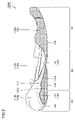
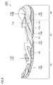
- FIG. 2 is a perspective view of the sole shown in FIG. 1, and FIGS. 3 and 4 are side views of the inner foot side and outer foot side of the sole shown in FIG. 1, respectively.
- 5 is a bottom view of the shoe sole shown in FIG. 1
- FIGS. 6A to 6C are sectional views along the VIA-VIA line and VIC-VIC line shown in FIG. 5, respectively.
- 7 is an exploded perspective view of the sole shown in FIG. 1
- FIG. 8 is a bottom view showing a state in which the outsole and the rear side midsole are removed from the sole shown in FIG. 9 is a perspective view showing a state in which the outsole is removed from the sole shown in FIG. 1.
- FIG. Next, the detailed structure of the shoe sole 100A according to the present embodiment will be described with reference to FIGS. 2 to 9.
- FIG. 1 the detailed structure of the shoe sole 100A according to the present embodiment will be described with reference to FIGS. 2 to 9.
- FIG. 1 the detailed structure of the shoe sole 100A according to the
- the sole 100A extends in the front-rear direction (horizontal direction in FIGS. 3 and 4, FIG. 5 along the vertical direction in the figure), the forefoot portion R1 that supports the toe portion and the tread portion of the wearer's foot, the middle foot portion R2 that supports the tread portion of the wearer's foot, and the wearer's It is divided into a rear foot part R3 that supports the heel part of the foot.
- the position equivalent to 40% of the dimension in the front-rear direction of the sole 100A from the front end is defined as the first boundary position
- the sole is measured from the front end.
- the forefoot portion R1 is a portion included between the front end and the first boundary position along the longitudinal direction
- the middle foot portion R2 corresponds to a portion included between the first boundary position and the second boundary position along the front-rear direction
- the rear foot portion R3 corresponds to the second boundary position along the front-rear direction. and the rear end of the shoe sole.
- the shoe sole 100A extends along the left-right direction (the left-right direction in the drawing), which is the direction that matches the foot width direction of the wearer's foot in plan view.
- the part on the inner foot side (the part on the S1 side shown in the figure), which is the median side (that is, the side close to the midline) in the anatomical upright position, and the side opposite to the midline side in the anatomical upright position of the foot ( That is, it is divided into a portion on the side of the outer foot (a portion on the side of S2 shown in the drawing), which is the side far from the midline).
- the boundary line that divides the sole 100A into the inner foot side portion and the outer foot side portion is the so-called shoe center.
- This shoe center connects the portion between the first and second toes of the wearer and the central portion of the calcaneus when worn by a standard wearer having a foot of a size suitable for the shoe 1.
- This is a straight line obtained by projecting a straight line onto the sole 100A along the vertical direction. Note that the front end and rear end of the sole 100A described above are the ends of the sole 100A located on this boundary line.
- the sole 100A has the midsole 110, the reinforcing structure 120, and the outsole 130, as described above.
- the midsole 110 includes an upper surface, a lower surface, and side surfaces connecting the upper surface and the lower surface, and constitutes an upper portion of the sole 100A.
- the outsole 130 includes an upper surface and a lower surface as the ground contact surface 134 described above, and constitutes a portion on the lower side of the sole 100A.
- the reinforcement structure 120 is located so that most of it covers the lower surface of the midsole 110 .
- the midsole 110 is positioned continuously from the forefoot portion R1 to the rearfoot portion R3.
- the midsole 110 includes a front midsole 110A and a rear midsole 110B, and is configured by combining the front midsole 110A and the rear midsole 110B.
- the front midsole 110A is positioned across the forefoot portion R1, the middle foot portion R2, and the portion near the front end of the rear foot portion R3, and the rear midsole 110B is positioned across the middle foot portion R2. It is positioned straddling the portion near the rear end and the rear foot portion R3.
- the rear end portion of the front midsole 110A and the front end portion of the rear midsole 110B are aligned. , overlap in the vertical direction (that is, the direction orthogonal to both the front-rear direction and the left-right direction) (especially see FIGS. 6A, 6B, 7, etc.). More specifically, in this portion, the front midsole 110A and the rear midsole 110A are positioned on the upper 200 side and the rear midsole 110B is positioned on the outsole 130 side. 110B are superimposed.
- the midsole 110 is formed by the front midsole 110A in the forefoot portion R1 and the portion near the front end of the middle foot portion R2, and the portion near the rear end of the middle foot portion R2 and the rearfoot portion R3
- the portion near the front end of the rear foot portion R3 is composed of a front midsole 110A and a rear midsole 110B where the midsole 110 is superimposed.
- a sole 110 is composed of a rear midsole 110B.
- the upper surface of the midsole 110 defines the upper surface of the sole 100A, and has a shape in which the periphery is raised compared to the surroundings (especially see FIGS. 3, 4 and 6). As a result, a concave portion is provided on the upper surface of midsole 110 , and this concave portion serves as a portion for receiving upper 200 .
- the upper surface of midsole 110 excluding the peripheral edge, which is the bottom surface of this concave portion, has a smooth curved surface shape so as to fit the sole of the wearer's foot.
- the outsole 130 is generally positioned continuously from the forefoot portion R1 to the rearfoot portion R3, except for a portion of the middle foot portion R2.
- the outsole 130 includes a rear inner foot side outsole 131 as a first cover portion, a rear outer foot side outsole 132 as a second cover portion, and a front outsole 133 as a third cover portion.
- the front outsole 133 is located across the forefoot portion R1 and the portion near the front end of the middle foot portion R2, and the rear inner foot side outsole 131 and the rear outer foot side outsole 132 is positioned straddling the portion near the rear end of the middle foot portion R2 and the rear foot portion R3.
- the rear inner foot side outsole 131 is positioned on the inner foot side between the rear end portion of the middle foot portion R2 and the rear foot portion R3. It is positioned at the outer foot side portion between the portion near the rear end of the portion R2 and the rear foot portion R3.
- each of the rear inner foot side outsole 131, the rear outer foot side outsole 132, and the front side outsole 133 constitutes the ground contact surface 134 as described above, and thus has grip properties.
- a tread pattern may be formed by forming unevenness on the exposed surface.
- Each of the rear inner foot side outsole 131 , the rear outer foot side outsole 132 and the front side outsole 133 has its upper surface joined to the lower surface of the midsole 110 .
- outsole 130 The detailed configuration of the outsole 130 and the midsole 110 to which it is joined, and the specific shape of the outsole 130 will be described in detail later.
- Midsole 110 (that is, front midsole 110A and rear midsole 110B) preferably has moderate strength and excellent cushioning properties. From this point of view, midsole 110 includes: A resin foam material containing a resin material as a main component and a foaming agent and a cross-linking agent as subcomponents is used. Alternatively, a rubber foam material containing a rubber material as a main component and a plasticizer, a foaming agent, a reinforcing agent, and a cross-linking agent as subcomponents may be used.
- the resin material for example, ethylene-vinyl acetate copolymer (EVA), polyolefin resin, thermoplastic polyurethane, thermoplastic polyamide elastomer (TPA, TPAE), or thermoplastic polyester elastomer can be used.
- EVA ethylene-vinyl acetate copolymer
- polyolefin resin polyolefin resin
- thermoplastic polyurethane thermoplastic polyurethane
- thermoplastic polyamide elastomer thermoplastic polyamide elastomer
- TPAE thermoplastic polyamide elastomer
- thermoplastic polyester elastomer thermoplastic polyester elastomer
- the midsole 110 generally has a smaller Young's modulus than the outsole 130 and is composed of a softer member. Therefore, the midsole 110 is elastically deformed relatively easily when a compressive load is applied, thereby providing excellent cushioning properties.
- Various cushioning parts may be included in predetermined portions of the midsole 110, and reinforcing parts other than the reinforcing structure 120 described later may be included.
- the outsole 130 (that is, the rear inner foot side outsole 131, the rear outer foot side outsole 132, and the front side outsole 133) preferably has excellent abrasion resistance and grip properties.
- a member made of a material containing a rubber material as a main component and a plasticizer, a reinforcing agent, and a cross-linking agent as subcomponents is used.
- butadiene rubber can be suitably used as the rubber material.
- the outsole 130 generally has a higher Young's modulus than the midsole 110 and is made of a hard material. Therefore, the outsole 130 is not easily deformed compared to the midsole 110 even when subjected to a compressive load, but is excellent in durability such as abrasion resistance. Note that the shape of the outsole 130 and the tread pattern described above can be appropriately designed according to the use of the shoe 1 .
- the reinforcing structure 120 is arranged so that most of it is located in the midfoot region R2, while a portion of it reaches the forefoot region R1 and the rearfoot region R3.
- the reinforcing structure 120 includes an inner leg-side reinforcing member 121 arranged on the inner leg side and an outer leg-side reinforcing member 122 arranged on the outer leg side.
- Both the inner foot side reinforcing member 121 and the outer foot side reinforcing member 122 are joined to the lower surface and side surface of the front midsole 110A and the upper surface of the rear midsole 110B. More specifically, the lower surface and side surfaces of the front midsole 110A are provided with recesses having shapes corresponding to the inner foot-side reinforcing member 121 and the outer foot-side reinforcing member 122.
- the foot-side reinforcing member 122 is joined to the front midsole 110A and the rear midsole 110B while being accommodated in these recesses.
- Both the inner foot side reinforcing member 121 and the outer foot side reinforcing member 122 are made of a material having higher rigidity than the material of the outsole 130 . That is, the inner foot side reinforcing member 121 and the outer foot side reinforcing member 122 have a higher Young's modulus and are harder than the outsole 130 .
- Materials constituting the inner leg side reinforcing member 121 and the outer leg side reinforcing member 122 are not particularly limited, but examples thereof include urethane-based thermoplastic elastomer (TPU), amide-based thermoplastic elastomer (TPA), Non-fiber reinforced resin made of polymer resin such as ethylene-vinyl acetate copolymer (EVA), fiber reinforced resin using carbon fiber, glass fiber, aramid fiber, Dyneema fiber, Zylon fiber, boron fiber, etc. as reinforcing fiber, etc. can be preferably used.
- TPU thermoplastic elastomer
- TPA amide-based thermoplastic elastomer
- EVA ethylene-vinyl acetate copolymer
- fiber reinforced resin using carbon fiber, glass fiber, aramid fiber, Dyneema fiber, Zylon fiber, boron fiber, etc. can be preferably used.
- the inner foot side reinforcing member 121 is slanted so as to reach from a portion near the front end of the outer foot side of the forefoot portion R1 to a portion near the rear end of the middle foot portion R2 on the inner foot side.
- the outer foot reinforcing member 122 extends from a portion near the rear end of the outer foot side of the forefoot portion R1 toward the rear end of the inner foot side of the middle foot portion R2. It includes an outer leg side bar portion 122a extending obliquely to reach the portion of the foot.
- inner foot side bar portion 121a and outer foot side bar portion 122a are positioned apart from each other, particularly in the middle foot portion R2.
- An intervening portion 116 made of a portion of the midsole 110 (more strictly, a portion of the front midsole 110A) made of a material with lower rigidity than 122 is located.
- the inner leg side portion of the forefoot portion R1 and the outer leg side portion of the rear foot portion R3 are positioned around the direction in which the interposed portion 116 extends at the position where the interposed portion 116 is provided. Since torsion is likely to occur between them, the impulse of the brake during the turning operation increases accordingly, and as a result, a quick and smooth turning operation can be realized.
- the inner leg side bar portion 121a and the outer leg side bar portion 122a are both provided so that their front ends reach the forefoot portion R1, and the portion located in the forefoot portion R1 is provided. Both the inner leg side bar portion 121a and the outer leg side bar portion 122a extend across a portion corresponding to the metatarsal phalanx of the wearer's foot (the portion indicated by the symbol MP in the drawing). . With this configuration, a greater propulsive force can be obtained due to the restoring force of the inner foot side bar portion 121a and the outer foot side bar portion 122a elastically deformed with the dorsiflexion of the sole 100A at the time of kicking. As a result, the acceleration assistance function and the driving assistance function can be improved.
- front midsole 110A is reinforced as described above.
- the member 121 and the outer leg side reinforcing member 122 are assembled. Therefore, after the rear midsole 110B is attached to the front midsole 110A, as shown in FIGS. 6A and 6B, the inner foot side reinforcing member 121 and the outer foot side reinforcing member Each rear end portion of 122 is sandwiched between the front midsole 110A and the rear midsole 110B, and these portions are embedded in the midsole 110 so that they are not exposed to the outside.
- Mutual bonding may be performed by any method, but can be performed by, for example, adhesion.
- the midsole 110 is provided with a first projecting portion 111 and a second projecting portion 112 projecting toward the ground contact surface 134 side. Both the first projecting portion 111 and the second projecting portion 112 are provided at positions on the lower surface side of the rear midsole 110B.
- the first projecting portion 111 is provided on the inner foot side and the rear end side of the shoe sole 100A
- the second projecting portion 112 is provided on the outer foot side and the rear end side of the shoe sole 100A. position.
- the first projecting portion 111 extends from the inner foot side rear end portion of the middle foot portion R2 to the inner foot side rear end portion of the rear foot portion R3.
- the second projection 112 extends along the front-rear direction of 100A, and extends from a portion near the rear end of the middle foot portion R2 on the outer foot side to a portion near the rear end of the rear foot portion R3 on the outer foot side. It extends along the front-rear direction of the sole 100A so as to straddle.
- the lower surface of the midsole 110 (more strictly, the lower surface of the rear midsole 110B) located between the first projecting portion 111 and the second projecting portion 112 has a front-rear direction of the sole 100A.
- the first protrusion 111 includes a first bottom surface 111a located on the side of the contact surface 134 and a first side surface located on the inner foot side when viewed from the first bottom surface 111a. 111b.
- the first bottom surface 111a and the first side surface 111b are smoothly connected.
- the other side surface of the first projecting portion 111 located on the outer leg side when viewed from the first bottom surface 111a defines the groove portion 113 described above.
- a rear inner foot side outsole 131 as a first cover portion is assembled to the first projecting portion 111 .
- the rear inner foot side outsole 131 includes a first bottom wall portion 131a that covers the first bottom surface 111a of the first projecting portion 111, and a first side wall portion that covers the first side surface 111b of the first projecting portion 111. 131b.
- the first bottom wall portion 131a covers the first bottom surface 111a to define the above-described ground contact surface 134, and the first side wall portion 131b extends upward from the inner leg side peripheral edge of the first bottom wall portion 131a. It covers the first side surface 111b by standing upright.
- the second projecting portion 112 includes a second bottom surface 112a located on the ground contact surface 134 side and a second side surface 112b located on the outer leg side when viewed from the second bottom surface 112a.
- the second bottom surface 112a and the second side surface 112b are smoothly connected.
- the other side surface of the second projecting portion 112 located on the inner leg side when viewed from the second bottom surface 112a defines the groove portion 113 described above.
- a rear outer foot side outsole 132 as a second cover portion is assembled to the second projecting portion 112 .
- the rear outer foot side outsole 132 includes a second bottom wall portion 132a that covers the second bottom surface 112a of the second projecting portion 112, and a second side wall portion that covers the second side surface 112b of the second projecting portion 112. 132b.
- the second bottom wall portion 132a covers the second bottom surface 112a to define the above-described ground contact surface 134, and the second side wall portion 132b extends upward from the outer leg side peripheral edge of the second bottom wall portion 132a. It covers the second side surface 112b by standing upright.
- the ground contact surface 134 defined by the first bottom wall portion 131a and the second bottom wall portion 132a is the portion that contacts the ground when the wearer is standing on a flat ground. More specifically, this corresponds to the hatched portions in FIGS. 10 and 12, which will be described later. Only the hatched portions of the first bottom wall portion 131a and the second bottom wall portion 132a correspond to this (that is, only the portions that contact the flat ground when standing correspond to this). Parts not marked with (i.e. parts not in contact with flat ground when standing) are not included.
- the front outsole 133 as the third cover portion is joined to the lower surface of the front midsole 110A.
- the front outsole 133 is located across the forefoot portion R1 and a portion near the front end of the middle foot portion R2, and the third bottom wall portion 133a covers the lower surface of the front midsole 110A in this portion. contains.
- the front outsole 133 has a third side wall portion erected from the peripheral edge of the third bottom wall portion 133a, and the third side wall portion covers the side surface of the front midsole 110A.
- the part that contacts the ground in the initial stage of landing is the rear part of the sole. Focusing on the part on the inner foot side, improvements were made to increase the cushioning performance of this part.
- the entire shoe is tilted to the inner foot side and the forefoot part is raised above the rear foot part (that is, the wearer's foot is tilted inward and the toe part is raised). In many cases, landing is performed with the heel raised above the heel). The entire bottom contact surface will land.
- the first projecting portion 111 and the second projecting portion 112 projecting toward the ground contact surface 134 are provided.
- the rear end portion of the midsole 110 in a state divided into the inner foot side and the outer foot side (in other words, by providing the rear end portion of the midsole 110 along the front and back direction of the sole 100A.
- the groove portion 113 extending along the length of the shoe sole 100A, the deformability of the portion on the rear inner foot side of the sole 100A is enhanced, thereby improving the cushioning performance during the cross-cutting motion.
- the portion of the sole where the first projecting portion 111 is provided precedes the other portions.
- 100A touches the ground the first protrusion 111 is rapidly and greatly deformed without being affected by other parts of the midsole 110, and the impact transmitted to the wearer is transferred to the wearer by the deformation of the first protrusion 111. It is absorbed, and as a result, a large cushioning performance can be obtained.
- the shape of the inner foot side peripheral edge of the shoe sole 100A in the portion where the first projecting portion 111 is provided More specifically, by devising the shape of the portion corresponding to the later-described specific region SR (see FIGS. 10 to 12) of the perimeter, the cushioning performance is improved and the stability when standing is improved. We are trying to achieve both This point will be described in detail below.
- FIG. 10(A) is an enlarged bottom view of a portion including a specific region of the sole shown in FIG. 1, and FIGS. 10(B) to 10(D) are XB-XB shown in FIG.
- FIG. 4 is a partial cross-sectional view along line XD--XD
- FIG. 11(A) is an enlarged side view of the inner foot side of the part including the specific region of the sole shown in FIG. 1, and FIGS. It is a partial cross-sectional view along the XIB-XIB line or XID-XID line shown.
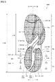
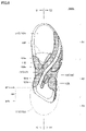
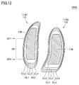
- FIG. 12 is a schematic diagram showing the shape of the outsole of the sole shown in FIG.
- the specific region SR is a region having a predetermined width in the front-rear direction of the sole 100A.
- the side position is defined by the rear side specific position SP2.
- the specific region SR includes a portion near the rear end of the middle foot portion R2 and a portion near the front end of the rear foot portion R3.
- the front side specific position SP1 is based on the front end of the sole 100A in the front-rear direction, and extends from the front end to the rear end of the sole 100A in the front-rear direction. It is a position corresponding to 70% of the dimension (corresponding to the distance L100 shown in the figure) (corresponding to the distance L70 shown in the figure).
- the rear side specific position SP2 is a position on the rear end side of the first bottom wall portion 131a of the rear inner foot side outsole 131 as the first cover portion (that is, the position provided on the rear inner foot side outsole 131). This is the position corresponding to the rear end position of the ground contact surface 134 in the standing position described above).
- the specific region SR located between the front specific position SP1 and the rear specific position SP2 is a region including a portion that contacts the ground at the initial stage of the above-described turning motion, and more specifically, The end of the specific region SR on the inner foot side comes into contact with the ground only in the initial stage of the turning motion.
- the first bottom wall portion 131a and the first side wall portion 131b are The first ridge line RL1 of the rear inner foot side outsole 131 located on the boundary of the rear inner foot side outsole 131 defined by the first side wall portion 131b as it goes from the front side specific position SP1 to the rear side specific position SP2. is positioned away from the first outline OL1.
- the distance between the first edge line RL1 and the first outline OL1 increases toward the rear side. That is, the distances D11 to D13 satisfy the condition D11 ⁇ D12 ⁇ D13.
- first bottom wall portion 131a and the first side wall portion 131b are formed so as to be continuous with each other, the above-described conditions are satisfied, so that the first ridgeline RL1 and the first outline OL1
- the portion of the first side wall portion 131b located between the first ridgeline RL1 and the first outline OL1 is a portion that touches the ground prior to other portions in the initial stage of the above-described turning operation.
- the first side wall portion 131b in the portion located between the first ridgeline RL1 and the first outline OL1 is made larger toward the rear side.
- the shock absorbing property during the turning motion is improved, but also the stability during the standing position can be sufficiently secured. Therefore, by using the shoe 1 according to the present embodiment and the sole 100A provided therein, the shoe sole that achieves both stability in the standing position and shock-absorbing properties in the turning motion, and the It can be a shoe with.
- the first side surface 111b of the first projecting portion 111 of the midsole 110 has an upper side surface 111b1 substantially orthogonal to the ground contact surface 134 and a first bottom surface. 111a and a lower side surface 111b2 that smoothly connects the upper side surface 111b1, and as shown in FIG. It includes a covering upper first sidewall portion 131b1 and a lower first sidewall portion 131b2 covering a lower side surface 111b2.
- the upper first side wall portion 131b1 and the lower first side wall portion 131b1 are separated from each other.
- the second ridgeline RL2 of the rear inner foot side outsole 131 located at the boundary with the side wall portion 131b2 moves from the front side specific position SP1 toward the rear side specific position SP2, the rear inner side defined by the first bottom wall portion 131a increases. It is positioned away from the second outline OL2 of the foot-side outsole 131 .
- the distance between the second edge line RL2 and the second outline line OL2 increases toward the rear side. That is, the distances D21 to D23 satisfy the condition D21 ⁇ D22 ⁇ D23.
- the lower first side wall portion 131b2 which is the portion of the first side wall portion 131b located between the second ridgeline RL2 and the second outline OL2, increases in size toward the rear side. growing.
- the lower first side wall portion 131b2 located between the second ridgeline RL2 and the second outline OL2 is the portion that touches the ground prior to other portions in the initial stage of the above-described turning operation. Therefore, by satisfying the condition, the impact cushioning performance during the steering operation can be improved.
- the portion of the first side wall portion 131b located between the first ridgeline RL1 and the first outline OL1 that is, the above-described
- the radius of curvature of the surface of the lower first side wall portion 131b2 located between the second ridgeline RL2 and the second outline OL2 gradually increases from the front side specific position SP1 toward the rear side specific position SP2.
- the sole 100A includes a contact surface 134 of a portion included in the specific region SR and an outsole when cut along the XIIA-XIIA line or XIID-XIID line shown in FIG. 130 contour lines are superimposed on each other and drawn, a specific condition is satisfied.
- the curve CL0 represents the contour line of the ground plane 134
- the curves CL1 to CL4 are at positions separated from the ground plane 134 by distances of 1 mm, 2 mm, 3 mm, and 4 mm, respectively.
- the outline of the cut surface of the rear inner foot side outsole 131 and the rear outer foot side outsole 132 is shown. That is, the curves CL0 to CL4 are so-called contour lines.
- the curves CL0 to CL4 of the portion corresponding to the inner foot side of the rear inner foot side outsole 131 correspond to the portion of the sole 100A that touches the ground prior to other portions in the initial stage of the above-described turning motion.
- the curves CL0 to CL4 of the relevant portion satisfy the above conditions, so that the impact cushioning performance at the time of turning back can be improved.
- a constricted portion 131c is provided at the upper end portion of the first side wall portion 131b of the rear inner foot side outsole 131. As shown in FIG. This constricted portion 131c is formed by providing a notch in the upper end portion of the first side wall portion 131b. The upper end of 131b is located closer to the ground plane 134 than the surroundings.
- the rear inner foot side outsole 131 When configured in this manner, the rear inner foot side outsole 131 can be deformed so as to bend in the front-rear direction with the portion where the constricted portion 131c is provided as a base point. It is possible to increase the deformability of the portion on the rear inner foot side, thereby further improving the cushioning performance during the turning motion.
- FIG. 13 in the sole 100A, the shape of the groove 113 of the midsole 110 provided between the first projecting portion 111 and the second projecting portion 112 is also devised.
- 13(A) to 13(C) are cross-sectional views of the entire shoe sole at the same positions as the cross-sections shown in FIGS. 10(B) to 10(D), respectively.
- the groove 113 formed between the first projection 111 and the second projection 112 extends along the longitudinal direction of the sole 100A as described above. contains existing parts. As described above, the groove 113 is provided in the rear end side portion of the midsole 110 to enhance the deformability of the rear inner foot side portion of the sole 100A. This is intended to improve the cushioning performance during the steering operation.
- the longitudinal direction of the sole 100A is measured.
- the sole 100A is cut along a plane perpendicular to , and in the cross section, a virtual line VL connecting the end points P1 and P2 of the midsole 110 that defines the opening surface 113a of the groove 113, and the virtual line VL
- the area Q1 surrounded by the virtual line VL, the perpendicular bisector VB, and the inner leg side portion of the contour of the groove 113 is the virtual line. It is configured to be larger than the area Q2 surrounded by VL, the perpendicular bisector VB, and the portion of the outline of the groove 113 on the outer leg side.
- the side surface of the first projecting portion 111 opposite to the first side surface 111b (that is, the lateral side of the first projecting portion 111 defined by the groove portion 113 described above). has a steeper slope in general, the first protrusion 111 is more likely to be deformed from the root side portion of the first protrusion 111 as a base point. Therefore, by configuring in this way, it becomes possible to enhance the deformability of the portion of the shoe sole 100A on the rear inner foot side, thereby further improving the cushioning performance during the turning motion. .
- the midsole 110 is divided into a front midsole 110A and a rear midsole 110B, which are superimposed to form a midsole. 110 is formed, the rear end portions of the inner foot side reinforcing member 121 and the outer foot side reinforcing member 122 are provided at the portion where the front midsole 110A and the rear midsole 110B are overlapped. 121b and 122b are embedded in midsole 110 by being sandwiched between front midsole 110A and rear midsole 110B.
- outsole 130 (rear inner foot side outsole 131 or rear outer foot side outsole 132), midsole 110 (rear side midsole 110B), from the side of ground contact surface 134 , Reinforcement structure 120 (inner foot side reinforcement member 121 or outer foot side reinforcement member 122), midsole 110 (front side midsole 110A). Since the midsole 110 is positioned directly above the outsole 130 without intervening, the cushioning function can be maximized.
- the outsole 130 attached to the rear end side portion of the midsole 110 serves as the first cover portion. It is divided into a foot side outsole 131 and a rear outer foot side outsole 132 as a second cover part (that is, the first cover part and the second cover part are separate members separated from each other). Therefore, they may be made of different materials.
- the rear inner foot side outsole 131 as the first cover part is made of a material having a lower rigidity than the material constituting the rear outer foot side outsole 132 as the second cover part, It is possible to increase the deformability of the portion of the sole 100A on the rear inner foot side, thereby further improving the cushioning performance during the turning motion.
- the first projecting portion 111 provided on the midsole 110 and the rear inner foot side outsole as the first cover portion 131 are provided on the inner foot side of the central position in the lateral direction of the sole 100A.
- FIG. 14(A) is an enlarged side view of the inner foot side of the part including the specific region of the shoe sole according to Embodiment 2, and FIGS. ) is a partial cross-sectional view taken along line XIVB-XIVB or XIVD-XIVD shown in FIG.
- a shoe sole 100B according to the present embodiment will be described with reference to FIG. Note that the sole 100B according to the present embodiment is provided in the shoe 1 in place of the sole 100A according to the first embodiment described above.
- concave streak portion 115 is provided at a predetermined position of midsole 110 in comparison with shoe sole 100A according to Embodiment 1 described above. The only difference is in the configuration.
- grooved portion 115 is formed on externally exposed surface 114 of midsole 110 .
- This externally exposed surface 114 is exposed above the first side wall portion 131b adjacent to the upper end portion of the first side wall portion 131b of the rear inner foot side outsole 131 as the first cover portion of the midsole 110.
- the concave streak portion 115 extends along the upper end portion of the first side wall portion 131b of the rear inner foot side outsole 131. As shown in FIG.
- the length of the recessed streak 115 is not particularly limited, it is preferably provided so as to overlap the specific region SR described above.
- the grooved portion 115 extends toward the front side and/or the rear side of the specific region SR beyond the front side specific position SP1 that is the front end of the specific region SR and/or the rear side specific position SP2 that is the rear end. may be
- the first protruding part 111 is easily deformed with the part where the concave streak part 115 is provided as a base point. Therefore, by configuring in this way, it is possible to further improve the deformability of the portion of the sole 100B on the rear inner foot side, thereby further improving the cushioning performance during the turning motion. Become.
- a sole according to certain aspects of the present disclosure includes a forefoot portion that supports the toe and tread portion of the wearer's foot, a midfoot portion that supports the tread portion of the wearer's foot, and a A rear foot part that supports the heel part of the foot is provided continuously along the front-rear direction, which is the direction that matches the length direction of the wearer's foot, and is composed of a midsole and an outsole.
- the midsole is provided so as to straddle the forefoot portion, the midfoot portion, and the rearfoot portion.
- the outsole covers at least a portion of the lower surface of the midsole to define a ground contact surface in a standing position.
- the midsole protrudes toward the ground contact surface at a position on the inner foot side in the left-right direction, which is the direction that matches the width direction of the wearer's foot, and on the rear end side in the front-rear direction. 1 protrusion.
- the portion of the midsole provided with the first projecting portion has a first bottom surface located on the side of the ground contact surface and a first side surface located on the inner foot side in the left-right direction when viewed from the first bottom surface. contains.
- the outsole includes a first bottom wall portion that defines the ground contact surface by covering the first bottom surface, and a peripheral edge of the first bottom wall portion on the inner foot side in the left-right direction. and a first cover portion including a first side wall portion covering the first side surface.
- position is defined as a front specific position
- a position of the rear end side of the first bottom wall in the front-rear direction is defined as a rear specific position.
- the first ridge line of the first cover portion located is defined by the first side wall portion from the front side specific position toward the rear side specific position when viewed along the normal direction of the ground contact surface. It is positioned away from the first profile line of the first cover part where the first cover part is located.
- the first projecting portion and the first cover portion are both positioned to straddle the middle foot portion and the rear foot portion. good too.
- both the first projecting portion and the first cover portion may be located on the inner foot side of the central position in the left-right direction.
- the first side surface includes an upper side surface substantially orthogonal to the ground contact surface and a lower portion smoothly connecting the first bottom surface and the upper side surface.
- the first sidewall portion may include an upper first sidewall portion covering the upper side surface and a lower first sidewall portion covering the lower side surface.
- the midsole is positioned on the outer foot side in the left-right direction and on the rear end side in the front-rear direction toward the ground contact surface side.
- You may have the 2nd protrusion part which protrudes.
- the portion of the midsole provided with the second projecting portion is positioned on the second bottom surface located on the side of the ground surface and on the outer foot side in the left-right direction when viewed from the second bottom surface.
- the outsole may include a second bottom wall portion that defines the ground contact surface by covering the second bottom surface, and the second bottom wall portion in the left-right direction.
- a second cover portion including a second side wall portion that covers the second side surface may be provided so as to stand upward from the peripheral edge of the outer leg side.
- the groove of the midsole formed between the first protrusion and the second protrusion extends along the front-rear direction.
- the midsole defining the opening surface of the groove in a cross section orthogonal to the front-rear direction at any position from the front specific position to the rear specific position and the perpendicular bisector of the virtual line are drawn, the inner foot side of the virtual line, the perpendicular bisector, and the contour line of the groove may be larger than the area surrounded by the imaginary line, the perpendicular bisector, and the outer leg side portion of the outline of the groove.
- first cover portion and the second cover portion may be separate members separated from each other.
- the material forming the first cover portion and the material forming the second cover portion may be different.
- a constricted portion may be provided at the upper end portion of the first side wall portion.
- the midsole includes an externally exposed surface exposed above the first side wall adjacent to the upper end of the first side wall.
- the externally exposed surface may be provided with a recess extending along the upper end of the first side wall.
- the sole according to one aspect of the present disclosure may further include a reinforcing structure assembled to the midsole.
- the reinforcing structure may be arranged so as to overlap at least a portion of the first cover when viewed along the normal direction of the ground contact surface.
- the reinforcing structure is embedded in the midsole at a portion where the reinforcing structure and the first cover overlap, so that the first cover, the midsole, and the reinforcing structure are formed from bottom to top. These may be located in the order of the part and the midsole.
- a shoe according to certain aspects of the present disclosure includes a sole according to certain aspects of the present disclosure described above and an upper positioned above the sole.
- the case where the first side wall portion located in the portion sandwiched between the first edge line and the first outline in the specific region SR is configured in a curved convex shape is exemplified.
- the shape of the portion is not particularly limited, and is preferably non-concave such as convex or flat, or may be concave such as curved concave.
- the shoes in which the upper body is configured to be brought into close contact with the foot by using the shoelace have been described as an example, but the upper body is attached to the foot by the hook-and-loop fastener.
- the shoe may be configured to be brought into close contact with the upper body, or may be made into a sock-shaped upper body so that the upper body can be brought into close contact with the foot only by inserting the foot into the upper body. . That is, the shape of the upper can be changed as appropriate according to the use of the shoe.
Landscapes
- Chemical & Material Sciences (AREA)
- Engineering & Computer Science (AREA)
- Materials Engineering (AREA)
- Footwear And Its Accessory, Manufacturing Method And Apparatuses (AREA)
Priority Applications (5)
| Application Number | Priority Date | Filing Date | Title |
|---|---|---|---|
| EP21937845.2A EP4309538B1 (en) | 2021-04-20 | 2021-04-20 | Shoe sole and shoe |
| CN202180097263.7A CN117177686A (zh) | 2021-04-20 | 2021-04-20 | 鞋底及鞋子 |
| US18/556,292 US12369682B2 (en) | 2021-04-20 | 2021-04-20 | Shoe sole and shoe |
| PCT/JP2021/016027 WO2022224348A1 (ja) | 2021-04-20 | 2021-04-20 | 靴底および靴 |
| JP2023515927A JP7699652B2 (ja) | 2021-04-20 | 2021-04-20 | 靴底および靴 |
Applications Claiming Priority (1)
| Application Number | Priority Date | Filing Date | Title |
|---|---|---|---|
| PCT/JP2021/016027 WO2022224348A1 (ja) | 2021-04-20 | 2021-04-20 | 靴底および靴 |
Publications (1)
| Publication Number | Publication Date |
|---|---|
| WO2022224348A1 true WO2022224348A1 (ja) | 2022-10-27 |
Family
ID=83722052
Family Applications (1)
| Application Number | Title | Priority Date | Filing Date |
|---|---|---|---|
| PCT/JP2021/016027 Ceased WO2022224348A1 (ja) | 2021-04-20 | 2021-04-20 | 靴底および靴 |
Country Status (5)
| Country | Link |
|---|---|
| US (1) | US12369682B2 (https=) |
| EP (1) | EP4309538B1 (https=) |
| JP (1) | JP7699652B2 (https=) |
| CN (1) | CN117177686A (https=) |
| WO (1) | WO2022224348A1 (https=) |
Families Citing this family (12)
| Publication number | Priority date | Publication date | Assignee | Title |
|---|---|---|---|---|
| US12507760B2 (en) * | 2021-04-07 | 2025-12-30 | Asics Corporation | Shoe sole and shoe |
| USD1074144S1 (en) * | 2023-03-24 | 2025-05-13 | Nike, Inc. | Shoe |
| USD1076364S1 (en) * | 2023-03-24 | 2025-05-27 | Nike, Inc. | Shoe |
| USD1083328S1 (en) * | 2023-03-31 | 2025-07-15 | Nike, Inc. | Shoe |
| USD1102111S1 (en) * | 2023-04-17 | 2025-11-18 | Puma SE | Shoe |
| TWD233839S (zh) * | 2023-11-04 | 2024-09-21 | 美商史柯契爾 Ii 美國股份有限公司 (美國) | 鞋中底外圍 |
| USD1099495S1 (en) * | 2024-02-13 | 2025-10-28 | Skechers U.S.A., Inc. Ii | Midsole periphery |
| USD1093850S1 (en) | 2024-06-07 | 2025-09-23 | Nike, Inc. | Shoe |
| USD1067596S1 (en) * | 2024-06-07 | 2025-03-25 | Nike, Inc. | Shoe |
| USD1067597S1 (en) * | 2024-06-07 | 2025-03-25 | Nike, Inc. | Shoe |
| US12550971B2 (en) * | 2024-06-12 | 2026-02-17 | Puma SE | Article of footwear having a sole structure |
| US12569030B2 (en) * | 2024-06-12 | 2026-03-10 | Puma SE | Article of footwear having a sole structure |
Citations (2)
| Publication number | Priority date | Publication date | Assignee | Title |
|---|---|---|---|---|
| WO2010049983A1 (ja) | 2008-10-27 | 2010-05-06 | 株式会社アシックス | プロネーションを抑制するのに適した靴底 |
| US20100293816A1 (en) * | 2008-02-27 | 2010-11-25 | Ecco Sko A/S | Sole for a shoe, in particular for a running shoe |
Family Cites Families (16)
| Publication number | Priority date | Publication date | Assignee | Title |
|---|---|---|---|---|
| US4557059A (en) * | 1983-02-08 | 1985-12-10 | Colgate-Palmolive Company | Athletic running shoe |
| JP3258628B2 (ja) | 1998-09-08 | 2002-02-18 | 株式会社アシックス | 運動靴 |
| JP3867054B2 (ja) * | 2003-02-10 | 2007-01-10 | 美津濃株式会社 | スポーツシューズのソール組立体 |
| DE112005002327B4 (de) * | 2004-09-30 | 2017-10-26 | Asics Corp. | Stoßabsorbierende Vorrichtung für eine Schuhsohle in einem Rückfußteil |
| US7905034B2 (en) * | 2007-07-09 | 2011-03-15 | Acushnet Company | Golf shoe outsole |
| US9750307B2 (en) * | 2013-02-21 | 2017-09-05 | Nike, Inc. | Article of footwear having a sole structure including a fluid-filled chamber and an outsole, the sole structure, and methods for manufacturing |
| GB201112362D0 (en) * | 2011-07-18 | 2011-08-31 | Fitflop Ltd | An item of footwear |
| US9609913B2 (en) * | 2011-12-29 | 2017-04-04 | Reebok International Limited | Sole and article of footwear having a pod assemby |
| WO2015052814A1 (ja) * | 2013-10-10 | 2015-04-16 | 株式会社アシックス | 靴底 |
| KR20160003944A (ko) * | 2014-07-01 | 2016-01-12 | 주식회사 엘에스네트웍스 | 기능성 신발 |
| US10123586B2 (en) * | 2015-04-17 | 2018-11-13 | Nike, Inc. | Independently movable sole structure |
| US9737109B2 (en) * | 2015-05-07 | 2017-08-22 | Nike, Inc. | Footwear with removable midsole and outsole |
| US20180199666A1 (en) * | 2015-06-26 | 2018-07-19 | Asics Corporation | Shoe having shoe sole with divided forefoot portion |
| WO2018070045A1 (ja) | 2016-10-14 | 2018-04-19 | 株式会社アシックス | 靴 |
| JP6913432B2 (ja) * | 2019-03-31 | 2021-08-04 | 美津濃株式会社 | シューズのソール構造体 |
| EP4096464B1 (en) * | 2020-04-07 | 2025-04-09 | NIKE Innovate C.V. | Footwear sole structure with nested foam core |
-
2021
- 2021-04-20 CN CN202180097263.7A patent/CN117177686A/zh active Pending
- 2021-04-20 EP EP21937845.2A patent/EP4309538B1/en active Active
- 2021-04-20 US US18/556,292 patent/US12369682B2/en active Active
- 2021-04-20 JP JP2023515927A patent/JP7699652B2/ja active Active
- 2021-04-20 WO PCT/JP2021/016027 patent/WO2022224348A1/ja not_active Ceased
Patent Citations (2)
| Publication number | Priority date | Publication date | Assignee | Title |
|---|---|---|---|---|
| US20100293816A1 (en) * | 2008-02-27 | 2010-11-25 | Ecco Sko A/S | Sole for a shoe, in particular for a running shoe |
| WO2010049983A1 (ja) | 2008-10-27 | 2010-05-06 | 株式会社アシックス | プロネーションを抑制するのに適した靴底 |
Non-Patent Citations (1)
| Title |
|---|
| See also references of EP4309538A4 |
Also Published As
| Publication number | Publication date |
|---|---|
| US12369682B2 (en) | 2025-07-29 |
| EP4309538A1 (en) | 2024-01-24 |
| EP4309538A4 (en) | 2024-04-24 |
| JPWO2022224348A1 (https=) | 2022-10-27 |
| JP7699652B2 (ja) | 2025-06-27 |
| CN117177686A (zh) | 2023-12-05 |
| US20240215680A1 (en) | 2024-07-04 |
| EP4309538B1 (en) | 2025-07-02 |
Similar Documents
| Publication | Publication Date | Title |
|---|---|---|
| JP7699652B2 (ja) | 靴底および靴 | |
| US12396515B2 (en) | Shoe sole and shoe | |
| US10470521B2 (en) | Sole structure for shoes and shoe with the sole structure | |
| JP7725570B2 (ja) | 靴底および靴 | |
| JP7085649B2 (ja) | シューズ | |
| CN101400272A (zh) | 鞋 | |
| JP2023055025A (ja) | プレート、ソール及び靴 | |
| JP3403952B2 (ja) | 靴底構造 | |
| JPWO2020136914A1 (ja) | 靴 | |
| JP7635260B2 (ja) | ソール構造およびシューズ | |
| JP3155765U (ja) | 靴底 | |
| WO2022215203A1 (ja) | 靴底および靴 | |
| EP1430803A2 (en) | Outsole assembly for a shoe | |
| CN219088528U (zh) | 一种轻便运动鞋及运动鞋底 | |
| JP3229046U (ja) | シューズ | |
| CN105188446A (zh) | 具有鞋前部板的鞋类物品 | |
| JP7836011B2 (ja) | シューズ | |
| JP7411179B2 (ja) | 靴のヒール | |
| WO2025074802A1 (ja) | 靴底 | |
| JP7481873B2 (ja) | シューズ用アッパー構造および当該アッパー構造を備えたシューズ | |
| US12616276B2 (en) | Shoe sole and shoe | |
| JP6987102B2 (ja) | ソールおよびそれを用いた自動車運転用シューズ | |
| EP4056067A1 (en) | Shoe sole and shoe comprising same | |
| KR20230149453A (ko) | 압력 분산 구조를 갖는 아웃솔 | |
| JP2026074289A (ja) | シューズ |
Legal Events
| Date | Code | Title | Description |
|---|---|---|---|
| 121 | Ep: the epo has been informed by wipo that ep was designated in this application |
Ref document number: 21937845 Country of ref document: EP Kind code of ref document: A1 |
|
| WWE | Wipo information: entry into national phase |
Ref document number: 2023515927 Country of ref document: JP Ref document number: 2021937845 Country of ref document: EP |
|
| WWE | Wipo information: entry into national phase |
Ref document number: 18556292 Country of ref document: US |
|
| ENP | Entry into the national phase |
Ref document number: 2021937845 Country of ref document: EP Effective date: 20231018 |
|
| NENP | Non-entry into the national phase |
Ref country code: DE |
|
| WWG | Wipo information: grant in national office |
Ref document number: 2021937845 Country of ref document: EP |
|
| WWG | Wipo information: grant in national office |
Ref document number: 18556292 Country of ref document: US |