WO2022220293A1 - コネクタ - Google Patents
コネクタ Download PDFInfo
- Publication number
- WO2022220293A1 WO2022220293A1 PCT/JP2022/017897 JP2022017897W WO2022220293A1 WO 2022220293 A1 WO2022220293 A1 WO 2022220293A1 JP 2022017897 W JP2022017897 W JP 2022017897W WO 2022220293 A1 WO2022220293 A1 WO 2022220293A1
- Authority
- WO
- WIPO (PCT)
- Prior art keywords
- inner housing
- housing
- engagement receiving
- receiving portion
- outer housing
- Prior art date
- Legal status (The legal status is an assumption and is not a legal conclusion. Google has not performed a legal analysis and makes no representation as to the accuracy of the status listed.)
- Ceased
Links
Images




Classifications
-
- H—ELECTRICITY
- H01—ELECTRIC ELEMENTS
- H01R—ELECTRICALLY-CONDUCTIVE CONNECTIONS; STRUCTURAL ASSOCIATIONS OF A PLURALITY OF MUTUALLY-INSULATED ELECTRICAL CONNECTING ELEMENTS; COUPLING DEVICES; CURRENT COLLECTORS
- H01R13/00—Details of coupling devices of the kinds covered by groups H01R12/70 or H01R24/00 - H01R33/00
- H01R13/02—Contact members
- H01R13/22—Contacts for co-operating by abutting
- H01R13/24—Contacts for co-operating by abutting resilient; resiliently-mounted
-
- H—ELECTRICITY
- H01—ELECTRIC ELEMENTS
- H01R—ELECTRICALLY-CONDUCTIVE CONNECTIONS; STRUCTURAL ASSOCIATIONS OF A PLURALITY OF MUTUALLY-INSULATED ELECTRICAL CONNECTING ELEMENTS; COUPLING DEVICES; CURRENT COLLECTORS
- H01R12/00—Structural associations of a plurality of mutually-insulated electrical connecting elements, specially adapted for printed circuits, e.g. printed circuit boards [PCB], flat or ribbon cables, or like generally planar structures, e.g. terminal strips, terminal blocks; Coupling devices specially adapted for printed circuits, flat or ribbon cables, or like generally planar structures; Terminals specially adapted for contact with, or insertion into, printed circuits, flat or ribbon cables, or like generally planar structures
- H01R12/70—Coupling devices
- H01R12/91—Coupling devices allowing relative movement between coupling parts, e.g. floating or self aligning
-
- H—ELECTRICITY
- H01—ELECTRIC ELEMENTS
- H01R—ELECTRICALLY-CONDUCTIVE CONNECTIONS; STRUCTURAL ASSOCIATIONS OF A PLURALITY OF MUTUALLY-INSULATED ELECTRICAL CONNECTING ELEMENTS; COUPLING DEVICES; CURRENT COLLECTORS
- H01R13/00—Details of coupling devices of the kinds covered by groups H01R12/70 or H01R24/00 - H01R33/00
- H01R13/02—Contact members
- H01R13/22—Contacts for co-operating by abutting
- H01R13/24—Contacts for co-operating by abutting resilient; resiliently-mounted
- H01R13/2407—Contacts for co-operating by abutting resilient; resiliently-mounted characterized by the resilient means
- H01R13/2421—Contacts for co-operating by abutting resilient; resiliently-mounted characterized by the resilient means using coil springs
-
- H—ELECTRICITY
- H01—ELECTRIC ELEMENTS
- H01R—ELECTRICALLY-CONDUCTIVE CONNECTIONS; STRUCTURAL ASSOCIATIONS OF A PLURALITY OF MUTUALLY-INSULATED ELECTRICAL CONNECTING ELEMENTS; COUPLING DEVICES; CURRENT COLLECTORS
- H01R13/00—Details of coupling devices of the kinds covered by groups H01R12/70 or H01R24/00 - H01R33/00
- H01R13/44—Means for preventing access to live contacts
- H01R13/447—Shutter or cover plate
- H01R13/453—Shutter or cover plate opened by engagement of counterpart
- H01R13/4538—Covers sliding or withdrawing in the direction of engagement
-
- H—ELECTRICITY
- H01—ELECTRIC ELEMENTS
- H01R—ELECTRICALLY-CONDUCTIVE CONNECTIONS; STRUCTURAL ASSOCIATIONS OF A PLURALITY OF MUTUALLY-INSULATED ELECTRICAL CONNECTING ELEMENTS; COUPLING DEVICES; CURRENT COLLECTORS
- H01R13/00—Details of coupling devices of the kinds covered by groups H01R12/70 or H01R24/00 - H01R33/00
- H01R13/46—Bases; Cases
- H01R13/502—Bases; Cases composed of different pieces
- H01R13/508—Bases; Cases composed of different pieces assembled by a separate clip or spring
-
- H—ELECTRICITY
- H01—ELECTRIC ELEMENTS
- H01R—ELECTRICALLY-CONDUCTIVE CONNECTIONS; STRUCTURAL ASSOCIATIONS OF A PLURALITY OF MUTUALLY-INSULATED ELECTRICAL CONNECTING ELEMENTS; COUPLING DEVICES; CURRENT COLLECTORS
- H01R12/00—Structural associations of a plurality of mutually-insulated electrical connecting elements, specially adapted for printed circuits, e.g. printed circuit boards [PCB], flat or ribbon cables, or like generally planar structures, e.g. terminal strips, terminal blocks; Coupling devices specially adapted for printed circuits, flat or ribbon cables, or like generally planar structures; Terminals specially adapted for contact with, or insertion into, printed circuits, flat or ribbon cables, or like generally planar structures
- H01R12/70—Coupling devices
- H01R12/71—Coupling devices for rigid printing circuits or like structures
- H01R12/712—Coupling devices for rigid printing circuits or like structures co-operating with the surface of the printed circuit or with a coupling device exclusively provided on the surface of the printed circuit
- H01R12/714—Coupling devices for rigid printing circuits or like structures co-operating with the surface of the printed circuit or with a coupling device exclusively provided on the surface of the printed circuit with contacts abutting directly the printed circuit; Button contacts therefore provided on the printed circuit
-
- H—ELECTRICITY
- H01—ELECTRIC ELEMENTS
- H01R—ELECTRICALLY-CONDUCTIVE CONNECTIONS; STRUCTURAL ASSOCIATIONS OF A PLURALITY OF MUTUALLY-INSULATED ELECTRICAL CONNECTING ELEMENTS; COUPLING DEVICES; CURRENT COLLECTORS
- H01R13/00—Details of coupling devices of the kinds covered by groups H01R12/70 or H01R24/00 - H01R33/00
- H01R13/02—Contact members
- H01R13/22—Contacts for co-operating by abutting
- H01R13/24—Contacts for co-operating by abutting resilient; resiliently-mounted
- H01R13/2464—Contacts for co-operating by abutting resilient; resiliently-mounted characterized by the contact point
- H01R13/2471—Contacts for co-operating by abutting resilient; resiliently-mounted characterized by the contact point pin shaped
Definitions
- This disclosure relates to connectors.
- Patent Document 1 discloses a probe pin having a terminal and a coil spring.
- the terminal has a plate shape and is supported by being engaged with the coil spring.
- An electrode contact portion is provided at the tip of the terminal. The electrode contact portion is pressed and brought into contact with the electrode to be inspected. When the urging force of the coil spring exceeds a predetermined value and the terminal is tilted in the plate width direction, the electrode contact portion slides on the electrode and the electrode is wiped.
- a plurality of probe pins are provided according to the number of electrodes to be inspected.
- Each of the plurality of probe pins has a terminal and a coil spring. Therefore, there is a problem that a coil spring is required for each terminal, resulting in an increase in cost. In addition, the fact that the shape of the terminal is restricted by the shape of the coil spring also causes an increase in cost.
- an object of the present disclosure is to provide a connector that can reduce costs.
- a connector of the present disclosure includes an outer housing, an inner housing arranged to be movable in a forward and backward direction with respect to the outer housing, a terminal held by the inner housing and having a distal end projecting from an end surface of the inner housing, a biasing member disposed between the outer housing and the inner housing and biasing the inner housing toward the advance side, wherein one of the inner housing and the outer housing has an engaging portion.
- the other side is provided with an engagement receiving portion that is in sliding contact with the engaging portion and moves the inner housing in a direction that intersects with the advancing/retreating direction.
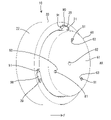
- FIG. 1 is an exploded perspective view of a connector according to an embodiment of the present disclosure
- FIG. FIG. 2 is a perspective view of the connector.
- FIG. 3 is a cross-sectional view of the connector.
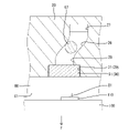
- FIG. 4 is an enlarged cross-sectional view showing a state in which the engaging portion is received by the front engagement receiving portion when the inner housing is in the advanced position.
- FIG. 5 is an enlarged cross-sectional view showing a state in which the engaging portion is in sliding contact with the engagement receiving portion while the inner housing moves from the advanced position to the retracted position.
- FIG. 6 is an enlarged cross-sectional view showing a state in which the engaging portion is received by the rear engagement receiving portion when the inner housing is in the retracted position.
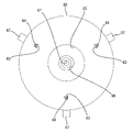
- FIG. 7 is a rear view of the inner housing.
- the connector of the present disclosure is (1) an outer housing, an inner housing arranged to be movable in a forward and backward direction with respect to the outer housing, a terminal held by the inner housing and having a distal end projecting from an end surface of the inner housing, and the outer housing. and a biasing member disposed between the inner housing and biasing the inner housing toward the advancing side, wherein one of the inner housing and the outer housing is provided with an engaging portion, On the other side, there is provided an engagement receiving portion that is in sliding contact with the engaging portion and moves the inner housing in a direction that intersects with the advancing/retreating direction.
- the inner housing is movable relative to the outer housing in the advancing and retreating direction and also in the direction intersecting the advancing and retreating direction. Can move in cross directions.
- the tip portion of the terminal can be pressed against the connection partner and slidably contacted, and the connection partner can be wiped.
- the terminals are held by the inner housing and the biasing member is arranged between the outer housing and the inner housing, the terminals and the biasing member do not affect each other.
- the number of terminals held by the inner housing can be freely set regardless of the biasing member. Therefore, the structure of the connector including the terminals can be simplified, and the cost can be reduced.
- the outer housing has a circumferential surface in sliding contact with the outer circumferential surface of the inner housing, and a direction intersecting with the forward/backward direction is a circumferential direction along the circumferential surface. According to the above configuration, since the inner housing can be rotated in the circumferential direction along the circumferential surface of the outer housing, the size of the connector is increased compared to the case where the inner housing moves radially with respect to the outer housing. can be suppressed.
- the biasing member is a coil spring centered on the axis of the circumferential surface, and the inner housing includes a plurality of terminal holding portions spaced around the center axis of the coil spring. It is good to have According to the above configuration, even when terminals are held by a plurality of terminal holding portions, there is no need to provide a plurality of biasing members, and preferably one biasing member can cover the situation. As a result, the number of parts can be reduced, and further cost reduction can be achieved.
- the engagement receiving portion may extend in a groove-like manner in a direction intersecting with the advance/retreat direction on the other side. According to the above configuration, it is possible to prevent the structure of the engagement receiving portion from becoming complicated.
- the other is provided with a groove-shaped front engagement receiving portion that communicates with the advancing-side end of the engagement receiving portion.
- the engaging portion may be received when the inner housing is in the advanced position. According to the above configuration, when the inner housing is at the advanced position, the front engagement receiving portion extending in the advancing/retreating direction receives the engaging portion. Therefore, the biasing force of the biasing member is maintained until the terminal starts wiping operation. can be stored to reach a contact pressure suitable for wiping the terminals.
- the other is provided with a groove-shaped rear engagement receiving portion that communicates with an end portion of the engagement receiving portion on the side opposite to the advancing side, and the rear engagement receiving portion extends in the advancing/retreating direction. to receive the engaging portion when the inner housing is in the retracted position.
- the rear engagement receiving portion extending in the advancing/retreating direction receives the engaging portion.
- the connector 10 includes an outer housing 20, an inner housing 60, a coil spring 50, a plurality of terminals 80 and a plurality of stoppers 90, as shown in FIG. Also, the connector 10 is incorporated into a module (not shown). The module is fitted and connected to a mating module (not shown). The module and the mating module maintain their connected state with each other by means of locks provided therein. The mating module is provided with a mating connection portion 110 to which the terminal 80 is connected. In the case of this embodiment, as shown in FIG.
- the inner housing 60 is incorporated into the outer housing 20 as shown in FIG. As shown in FIG. 3 , coil spring 50 is interposed between inner housing 60 and outer housing 20 .
- the inner housing 60 has an advanced position (see FIGS. 2, 3, and 4) where it advances from the outer housing 20 in response to the biasing force of the coil spring 50, and a position where the inner housing 60 resists the biasing force of the coil spring 50. and a retracted position (see FIG. 6) in which it retracts inside the outer housing 20. As shown in FIG.
- the plurality of terminals 80 are held by the inner housing 60 .
- a plurality of stoppers 90 are provided for each terminal 80 to restrict each terminal 80 from coming out of the inner housing 60 .
- the front-rear direction corresponds to the advancing/retreating direction of the inner housing 60 with respect to the outer housing 20, and the advancing side of the inner housing 60 is defined as the front side (see arrow F in the drawings).
- the circumferential direction is the direction around the axis AX of the connector 10 .
- the axis AX is a center axis parallel to the longitudinal direction of the connector 10 and corresponds to the radial centers of the outer housing 20 and the inner housing 60 .
- the outer housing 20 is made of synthetic resin. As shown in FIG. 1 , the outer housing 20 is cap-shaped and has a disk-shaped rear surface portion 21 and a cylindrical outer peripheral portion 22 protruding forward from the outer periphery of the rear surface portion 21 . An annular outer-side spring mounting portion 23 is protruded from the center portion of the front surface of the back portion 21 . As shown in FIG. 3, the later-described outer side mounting portion 51 of the coil spring 50 is fitted and supported in the recess of the outer side spring mounting portion 23 .
- a plurality of wire insertion holes 24 are provided through the rear portion 21 at intervals in the circumferential direction.
- the wire insertion holes 24 are arranged in the back portion 21 at three equal intervals in the circumferential direction.
- Each wire insertion hole 24 is formed in an elongated hole shape elongated in the circumferential direction.
- a wire 200 connected to a terminal 80 is inserted through each wire insertion hole 24 with play.
- the outer peripheral portion 22 has a circumferential surface 25 on its inner periphery.
- a plurality of engagement receiving portions 26 are recessed in the circumferential surface 25 of the outer peripheral portion 22 at intervals in the circumferential direction.
- the engagement receiving portions 26 are arranged at three equal intervals in the circumferential direction on the circumferential surface 25 of the outer peripheral portion 22 .
- the engagement receiving portion 26 has a groove-like shape extending in an oblique direction that intersects with the front-rear direction. Specifically, as shown in FIG. 5, the engagement receiving portion 26 is inclined with respect to the front-rear direction so as to be displaced to one side in the circumferential direction (to the right in FIG. 5) as it goes rearward.
- a plurality of rear engagement receiving portions 27 are recessed behind each engagement receiving portion 26 on the circumferential surface 25 of the outer peripheral portion 22 .
- the rear engagement receiving portion 27 has a groove-like shape extending in the front-rear direction on the circumferential surface 25 of the outer peripheral portion 22, and has a front end curvedly communicating with the engagement receiving portion 26 and a rear end closed along the circumferential direction. It is
- the rear engagement receiving portion 27 and the wire insertion hole 24 are arranged at positions overlapping each other in the circumferential direction.
- the length of the rear engagement receiving portion 27 in the front-rear direction is shorter than the length of the engagement receiving portion 26 in the oblique direction.
- a plurality of front engagement receiving portions 28 are recessed in front of each engagement receiving portion 26 on the circumferential surface 25 of the outer peripheral portion 22 .
- the front engagement receiving portion 28 has a groove shape extending in the front-rear direction on the circumferential surface 25 of the outer peripheral portion 22.
- the rear end of the front engagement receiving portion 28 is curved and communicates with the engagement receiving portion 26. It communicates with the stepped portion 31 of the stepped shape.
- the length of the front engagement receiving portion 28 in the front-rear direction is shorter than the length of the engagement receiving portion 26 in the oblique direction.
- a plurality of stopper receiving portions 29 are recessed in front of each front engagement receiving portion 28 on the circumferential surface 25 of the outer peripheral portion 22 .
- the stopper receiving portion 29 extends forward from the front engagement receiving portion 28 on the circumferential surface 25 of the outer peripheral portion 22 in a groove shape, and the front end of the stopper receiving portion 29 opens at the front end of the outer peripheral portion 22 .
- the stopper receiving portion 29 has a stepped portion 31 with a rectangular cross section that is widened in the circumferential direction.
- the inner housing 60 is made of synthetic resin. As shown in FIG. 2 , the inner housing 60 has a cylindrical shape and is fitted inside the outer housing 20 . The outer peripheral surface of the inner housing 60 is slidable along the circumferential surface 25 of the outer housing 20 in the circumferential direction. The inner housing 60 has a radial end surface 61 on its front surface. An axial hole 62 is provided in the radial center of the inner housing 60 so as to penetrate therethrough in the front-rear direction. A plurality of terminal holding portions 63 are provided in the inner housing 60 at intervals in the circumferential direction. The terminal holding portions 63 are arranged in the inner housing 60 at three equal intervals in the circumferential direction. As shown in FIG.
- the terminal holding portion 63 is a through hole extending in the front-rear direction, and has an elastically deformable lance 64 protruding forward in the middle of the extending direction.
- the rear surface of the inner housing 60 is provided with a fitting recess 65 having an annular shape when viewed from the rear.
- the fitting recess 65 has its center on the axis AX of the inner housing 60 where the axis hole 62 is located.
- the outer-side spring mounting portion 23 of the outer housing 20 is fitted and inserted into the fitting recess 65 .
- Each terminal holding portion 63 is arranged radially outside the fitting recess 65 .
- An inner side spring mounting portion 66 having an annular shape when viewed from the rear is opened on the inner surface of the fitting recess 65 on the rear surface of the inner housing 60 .
- the inner side spring mounting portion 66 is concentric with the fitting recess 65 and centered on the axis AX of the inner housing 60 .
- the inner-side spring mounting portion 66 extends forward from the inner surface of the fitting recess 65 and is closed at the front-rear intermediate portion of the inner housing 60 .
- An inner side mounting portion 52 of the coil spring 50 which will be described later, is fitted into and mounted on the inner side spring mounting portion 66 .
- the radial opening width of the inner side spring mounting portion 66 corresponds to the wire diameter of the coil spring 50 .
- a plurality of engaging portions 67 are protruded from the rear end portion of the outer peripheral surface of the inner housing 60 at intervals in the circumferential direction.
- the engaging portions 67 are arranged at three equal intervals in the circumferential direction on the outer peripheral surface of the inner housing 60 .
- the engaging portion 67 has a pin shape with a circular cross section and protrudes radially outward.
- a compression coil spring made of metal is exemplified as the coil spring 50 .
- the coil spring 50 has an outer mounting portion 51 mounted in a recess of the outer spring mounting portion 23 of the outer housing 20 at its rear end, and an inner spring mounting portion 51 of the inner housing 60 at its front end. It has an inner side mounting portion 52 that is mounted within the side spring mounting portion 66 .
- the outer peripheral surface of the outer side mounting portion 51 is arranged along the inner peripheral surface of the recess of the outer side spring mounting portion 23 .
- the inner peripheral surface and the outer peripheral surface of the inner side mounting portion 52 are arranged along the inner peripheral surface and the outer peripheral surface of the inner side spring mounting portion 66, respectively.
- the coil spring 50 is arranged between the outer housing 20 and the inner housing 60 in a natural state or a slightly compressed state. As shown in FIG. 2 , the front portion of the inner housing 60 is arranged to protrude forward from the outer housing 20 . On the other hand, when the inner housing 60 is in the retracted position, the coil spring 50 is strongly compressed between the outer housing 20 and the inner housing 60 .
- the inner housing 60 is arranged so as to protrude from the outer housing 20 less than when it is in the advanced position, or to retract entirely within the outer housing 20 .
- the terminal 80 is made of a highly conductive metal and has a shape elongated in the front-rear direction. As shown in FIG. 3, the terminal 80 includes a tab-shaped or pin-shaped connecting portion 81 projecting forward, and a barrel-shaped crimping portion 82 located behind the connecting portion 81 and crimped to the end of the electric wire 200 . and have The terminal 80 is inserted into the terminal holding portion 63 and retained in the terminal holding portion 63 by engaging the locking lance 64 with the rear end of the connecting portion 81 . With the terminal 80 locked to the lance 64 , the tip of the connecting portion 81 is arranged to protrude forward from the end surface 61 of the inner housing 60 .
- the electric wire 200 connected to the crimping portion 82 is drawn rearward from the rear surface of the inner housing 60 .
- the electric wires 200 are pulled out rearward from the electric wire insertion holes 24 of the outer housing 20 .
- the stopper 90 is made of synthetic resin and has a shape that can be fitted into the stopper receiving portion 29 of the outer housing 20 as shown in FIG.
- the stopper 90 has a widened portion 91 that protrudes from the body portion on both sides in the circumferential direction.
- the widened portion 91 of the stopper 90 is press-fitted into the stepped portion 31 of the stopper receiving portion 29 and fixed.
- the engagement portion 67 abuts against the stopper 90 from behind, thereby restricting the inner housing 60 from moving forward from the outer housing 20 .
- the inner housing 60 is biased by the coil spring 50 so that the engaging portion 67 can maintain a state of contact with the stopper 90 . In this manner, the inner housing 60 is retained at the advanced position with the front side projecting from the outer housing 20 .
- the module is mated with the other module.
- the connection portion 81 of the terminal 80 abuts against the mating connection portion 110 , and the inner housing 60 retreats against the biasing force of the coil spring 50 .
- the engaging portion 67 moves rearward on the front engagement receiving portion 28 and the coil spring 50 is compressed to accumulate a biasing force in the coil spring 50 .
- the connection portion 81 of the terminal 80 gradually increases the contact pressure with respect to the mating connection portion 110 by receiving the biasing force of the coil spring 50 .
- the engagement portion 67 enters the engagement receiving portion 26 and slides on the groove surface of the engagement receiving portion 26, as shown in FIG. Thereby, a rotational force is applied to the inner housing 60 and the inner housing 60 rotates about the axis AX with respect to the outer housing 20 .
- the terminal 80 held by the terminal holding portion 63 of the inner housing 60 is also displaced around the axis AX, and the distal end portion of the terminal 80 receives the biasing force of the coil spring 50 and the mating connection portion 110 is displaced. It slides on the surface to one side in the circumferential direction. As a result, the surface of the mating connection portion 110 is wiped, and the oxide film and the like are removed.
- the front surface of the rear surface portion 21 of the outer housing 20 and the rear surface of the inner housing 60 approach each other, and the inner housing 60 moves toward the retracted position.
- both modules are held in the fitted state by the locking action of the mutual locking portions.
- the front surface of the rear surface portion 21 of the outer housing 20 and the rear surface of the inner housing 60 face each other closely, and the outer-side spring mounting portion 23 of the outer housing 20 is fitted into the fitting recess 65 .
- the inner housing 60 reaches the retracted position, and the engagement portion 67 enters the rear engagement receiving portion 27 as shown in FIG.
- the rear engagement receiving portion 27 Since the rear engagement receiving portion 27 has a shape extending in the front-rear direction, no rotational force is applied to the inner housing 60 . Therefore, the inner housing 60 is maintained in a state where it does not rotate about the axis AX. On the other hand, both modules can be displaced in the front-rear direction within a movable range such as the tolerance of the locking portion. Therefore, the inner housing 60 can move in the front-rear direction with respect to the outer housing 20 at the retracted position. While the inner housing 60 moves to the retracted position, the connection portion 81 of the terminal 80 can be kept in contact with the mating connection portion 110 at a fixed position.
- the inner housing 60 is movable in the longitudinal direction with respect to the outer housing 20, and is also movable in the circumferential direction. Wiping can be performed by sliding on the surface of the mating connection portion 110 .
- the shape and arrangement of the terminals 80 are affected by the coil springs 50. do not have.
- the structure of the connector 10 including the terminals 80 can be simplified, and the cost can be reduced.
- the inner housing 60 can rotate in the circumferential direction inside the circumferential surface 25 of the outer housing 20 . Therefore, compared with the case where the inner housing 60 moves radially with respect to the outer housing 20, it is possible to suppress the connector 10 from increasing in size.
- the front engagement receiving portion 28 extending in the front-rear direction receives the engaging portion 67, so that the urging force of the coil spring 50 is applied until the terminal 80 starts wiping operation.
- a contact pressure suitable for terminal 80 to wipe can be reached.
- the rear engagement receiving portion 27 extending in the front-rear direction receives the engaging portion 67, so that the terminal 80 completes the wiping operation and the module incorporating the connector 10 is connected to the mating portion.
- the inner housing 60 can be moved within the movable range caused by the tolerance of the locking portion. As a result, the connection portion 81 of the terminal 80 can be in good contact with the mating connection portion 110 .
- the convex engaging portion was formed in the inner housing, and the concave engaging receiving portion was formed in the outer housing.
- the convex engaging portion may be formed on the outer housing and the concave engaging receiving portion may be formed on the inner housing.
- the inner housing is movable relative to the outer housing in the front-rear direction and in the circumferential direction orthogonal to the radial direction.
- the inner housing may be movable relative to the outer housing in a direction intersecting the front-rear direction, for example, in a radial direction.
- the mating connection of the terminal was the mating connection portion of the circuit board.
- the connection partner of the terminal is not limited to the circuit board, and may be, for example, a connection terminal or a bus bar.
- the coil spring was arranged between the inner housing and the outer housing.
- a biasing member may be arranged between the inner housing and the outer housing, for example, a leaf spring or a cushion may be arranged.
- one connector is provided with one biasing member.
- a single connector may be provided with multiple biasing members.
Landscapes
- Connector Housings Or Holding Contact Members (AREA)
- Details Of Connecting Devices For Male And Female Coupling (AREA)
Abstract
Description
最初に本開示の実施形態の態様を列記して説明する。
本開示のコネクタは、
(1)アウタハウジングと、前記アウタハウジングに対して進退方向に移動可能に配置されるインナハウジングと、前記インナハウジングに保持され、先端部を前記インナハウジングの端面から突出させる端子と、前記アウタハウジングと前記インナハウジングとの間に配置され、前記インナハウジングを進出側に付勢する付勢部材と、を備え、前記インナハウジングと前記アウタハウジングのうち、一方には、係合部が設けられ、他方には、前記係合部と摺接し、前記インナハウジングを前記進退方向と交差する方向に移動させる係合受部が設けられている。
ここで、端子がインナハウジングに保持され、付勢部材がアウタハウジングとインナハウジングとの間に配置されるため、端子と付勢部材とを互いに影響し合わない構造にすることができる。そして、インナハウジングに保持される端子の個数も付勢部材と関わりなく自由に設定することができる。したがって、端子を含むコネクタの構造を簡略化することができ、コストの低減を図ることができる。
上記構成によれば、インナハウジングがアウタハウジングの円周面に沿って周方向に回転することができるため、インナハウジングがアウタハウジングに対して径方向等に移動する場合に比べ、コネクタが大型化するのを抑制することができる。
上記構成によれば、複数の端子保持部にそれぞれ端子が保持される場合であっても、複数の付勢部材を設ける必要がなく、好ましくは、一つの付勢部材で賄うことができる。その結果、部品点数を削減でき、さらなるコストの低減を図ることができる。
上記構成によれば、係合受部の構造が複雑化するのを抑えることができる。
上記構成によれば、インナハウジングが進出位置にあるときに、進退方向に延びる前方係合受部が係合部を受け入れるため、端子がワイピング動作を開始するまでの間、付勢部材が付勢力を蓄えて、端子がワイピングするのに適した接圧に到達することができる。
上記構成によれば、インナハウジングが退入位置にあるときに、進退方向に延びる後方係合受部が係合部を受け入れるため、端子がワイピング動作を完了し、コネクタを組み込んだモジュール等が相手側のモジュールにロックされる場合に、ロック機構の公差等に起因する可動範囲内で、インナハウジングを移動させることができる。
本開示の実施形態の具体例を、以下に図面を参照しつつ説明する。なお、本発明はこの例示に限定されるものではなく、請求の範囲によって示され、請求の範囲と均等の意味および範囲内でのすべての変更が含まれることが意図される。
アウタハウジング20は合成樹脂製である。図1に示すように、アウタハウジング20は、キャップ状をなし、円板状の背面部21と、背面部21の外周から前方に突出する円筒状の外周部22と、を有している。背面部21の前面の中心部には、円環状のアウタ側ばね装着部23が突出して設けられている。図3に示すように、巻きばね50の後述するアウタ側装着部51は、アウタ側ばね装着部23の凹み内に嵌合して支持される。
インナハウジング60は合成樹脂製である。図2に示すように、インナハウジング60は、円柱状をなし、アウタハウジング20内に嵌合される。インナハウジング60の外周面は、アウタハウジング20の円周面25に沿って周方向に摺動可能とされている。インナハウジング60は、前面に、径方向に沿った端面61を有している。インナハウジング60の径方向中心には、前後方向に貫通する軸心孔62が設けられている。インナハウジング60には、周方向に間隔を置いて複数の端子保持部63が設けられている。各端子保持部63は、インナハウジング60において、周方向に3箇所等間隔を置いて配置される。図3に示すように、端子保持部63は、前後方向に延びる貫通孔であって、延び方向の途中に、前方に突出する弾性変形可能なランス64を有している。インナハウジング60がアウタハウジング20に組み付けられた状態において、端子保持部63と電線挿通孔24とは前後方向に同軸上に配置される。
巻きばね50としては、金属製の圧縮コイルスプリングが例示される。図3に示すように、巻きばね50は、後端部にアウタハウジング20のアウタ側ばね装着部23の凹み内に装着されるアウタ側装着部51を有し、前端部にインナハウジング60のインナ側ばね装着部66内に装着されるインナ側装着部52を有している。アウタ側装着部51の外周面は、アウタ側ばね装着部23の凹みの内周面に沿って配置される。インナ側装着部52の内周面および外周面は、それぞれインナ側ばね装着部66の内周面および外周面に沿って配置される。インナハウジング60が進出位置にあるときに、巻きばね50はアウタハウジング20とインナハウジング60との間に自然状態または少し圧縮された状態で配置される。図2に示すように、インナハウジング60の前部は、アウタハウジング20から前方に突出して配置される。これに対し、インナハウジング60が退入位置にあるときに、巻きばね50はアウタハウジング20とインナハウジング60との間に強く圧縮された状態で配置される。インナハウジング60は、進出位置にあるときよりもアウタハウジング20から小さく突出し、またはアウタハウジング20内に全体が引っ込むように配置される。
端子80は、導電性に優れた金属製であって、前後方向に細長く延びる形状になっている。図3に示すように、端子80は、前方に突出するタブ状またはピン状の接続部81と、接続部81の後方に位置して電線200の端部に圧着されるバレル状の圧着部82と、を有している。端子80は、端子保持部63内に挿入され、接続部81の後端にランス64を係止させることで、端子保持部63内に抜け止めされる。端子80がランス64に係止された状態で、接続部81の先端がインナハウジング60の端面61から前方に突出して配置される。圧着部82に接続された電線200は、インナハウジング60の後面から後方に引き出される。また、インナハウジング60がアウタハウジング20に組み付けられた状態において、電線200は、アウタハウジング20の電線挿通孔24から後方に引き出される。
ストッパ90は合成樹脂製であって、図2に示すように、アウタハウジング20のストッパ受部29に嵌合可能な形状になっている。ストッパ90は、本体部分から周方向の両側に張り出す形状の拡幅部91を有している。ストッパ90の拡幅部91は、ストッパ受部29の段部31に圧入して固定される。
まず、アウタハウジング20の電線挿通孔24に電線200の端部に接続された電線200を通し、その状態からインナハウジング60の端子保持部63に電線200の端部に接続された端子80を挿入して保持させる。次いで、アウタハウジング20とインナハウジング60との間に巻きばね50を介在させつつアウタハウジング20の外周部22の内側に前方からインナハウジング60を嵌め込む。このとき、アウタハウジング20の前方係合受部28にインナハウジング60の係合部67を挿入する。続いで、ストッパ受部29にストッパ90を圧入する。図3および図4に示すように、係合部67がストッパ90に後方から当接することで、インナハウジング60の、アウタハウジング20から前方への抜け出しが規制される。インナハウジング60は、巻きばね50によって付勢されることで、係合部67がストッパ90に当接する状態を維持することができる。このようにして、インナハウジング60は、アウタハウジング20に対して前部側を突出させた進出位置に留め置かれる。
今回開示された実施の形態はすべての点で例示であって制限的なものではないと考えるべきである。
上記実施形態の場合、凸状の係合部がインナハウジングに形成され、凹状の係合受部がアウタハウジングに形成されていた。しかし、他の実施形態によれば、凸状の係合部がアウタハウジングに形成され、凹状の係合受部がインナハウジングに形成されていても良い。
上記実施形態の場合、インナハウジングは、アウタハウジングに対して前後方向および径方向と直交する周方向に移動可能となっていた。しかし、他の実施形態によれば、インナハウジングは、アウタハウジングに対して前後方向と交差する方向に移動可能となっていれば良く、例えば、径方向に移動可能となっていても良い。
上記実施形態の場合、端子の接続相手は、回路基板の相手接続部であった。しかし、他の実施形態によれば、端子の接続相手は、回路基板に限らず、例えば、接続端子やバスバーであっても良い。
上記実施形態の場合、インナハウジングとアウタハウジングとの間に巻きばねが配置されていた。しかし、他の実施形態によれば、インナハウジングとアウタハウジングとの間に付勢部材が配置されていれば良く、例えば、板ばねやクッションが配置されていても良い。
上記実施形態の場合、一つのコネクタに一つの付勢部材が設けられていた。しかし、他の実施形態によれば、一つのコネクタに複数の付勢部材が設けられていても良い。
20…アウタハウジング
21…背面部
22…外周部
23…アウタ側ばね装着部
24…電線挿通孔
25…円周面
26…係合受部
27…後方係合受部
28…前方係合受部
29…ストッパ受部
31…段部
50…巻きばね(付勢部材)
51…アウタ側装着部
52…インナ側装着部
60…インナハウジング
61…端面
62…軸心孔
63…端子保持部
64…ランス
65…嵌合凹部
66…インナ側ばね装着部
67…係合部
80…端子
81…接続部
82…圧着部
90…ストッパ
91…拡幅部
100…回路基板
110…相手接続部
200…電線
AX…軸心
F…前側
Claims (6)
- アウタハウジングと、
前記アウタハウジングに対して進退方向に移動可能に配置されるインナハウジングと、
前記インナハウジングに保持され、先端部を前記インナハウジングの端面から突出させる端子と、
前記アウタハウジングと前記インナハウジングとの間に配置され、前記インナハウジングを進出側に付勢する付勢部材と、を備え、
前記インナハウジングと前記アウタハウジングのうち、一方には、係合部が設けられ、他方には、前記係合部と摺接し、前記インナハウジングを前記進退方向と交差する方向に移動させる係合受部が設けられている、コネクタ。 - 前記アウタハウジングは、前記インナハウジングの外周面と摺接する円周面を有し、
前記進退方向と交差する方向は、前記円周面に沿う周方向である、請求項1に記載のコネクタ。 - 前記付勢部材は、前記円周面の軸心を中心軸とする巻きばねであり、
前記インナハウジングは、前記巻きばねの前記中心軸の周りに間隔を置いて複数の端子保持部を有している、請求項2に記載のコネクタ。 - 前記係合受部は、前記他方において、前記進退方向と交差する方向に溝状に延びている、請求項1から請求項3のいずれか一項に記載のコネクタ。
- 前記他方には、前記係合受部における前記進出側の端部に連通する溝状の前方係合受部が設けられ、
前記前方係合受部は、前記進退方向に延び、前記インナハウジングが進出位置にあるときに、前記係合部を受け入れる、請求項4に記載のコネクタ。 - 前記他方には、前記係合受部における前記進出側とは反対側の端部に連通する溝状の後方係合受部が設けられ、
前記後方係合受部は、前記進退方向に延び、前記インナハウジングが退入位置にあるときに、前記係合部を受け入れる、請求項4または請求項5に記載のコネクタ。
Priority Applications (2)
| Application Number | Priority Date | Filing Date | Title |
|---|---|---|---|
| US18/286,530 US12531364B2 (en) | 2021-04-16 | 2022-04-15 | Connector with sliding circumferentially rotating inner housing |
| CN202280026884.0A CN117121306A (zh) | 2021-04-16 | 2022-04-15 | 连接器 |
Applications Claiming Priority (2)
| Application Number | Priority Date | Filing Date | Title |
|---|---|---|---|
| JP2021-069467 | 2021-04-16 | ||
| JP2021069467A JP7487701B2 (ja) | 2021-04-16 | 2021-04-16 | コネクタ |
Publications (1)
| Publication Number | Publication Date |
|---|---|
| WO2022220293A1 true WO2022220293A1 (ja) | 2022-10-20 |
Family
ID=83640680
Family Applications (1)
| Application Number | Title | Priority Date | Filing Date |
|---|---|---|---|
| PCT/JP2022/017897 Ceased WO2022220293A1 (ja) | 2021-04-16 | 2022-04-15 | コネクタ |
Country Status (4)
| Country | Link |
|---|---|
| US (1) | US12531364B2 (ja) |
| JP (1) | JP7487701B2 (ja) |
| CN (1) | CN117121306A (ja) |
| WO (1) | WO2022220293A1 (ja) |
Citations (5)
| Publication number | Priority date | Publication date | Assignee | Title |
|---|---|---|---|---|
| JP2002517076A (ja) * | 1998-05-22 | 2002-06-11 | レイプール テクノロジー アクティーゼルスカブ | 電気的接触を提供する手段 |
| JP2003045541A (ja) * | 2001-07-30 | 2003-02-14 | Hosiden Corp | コネクタ |
| JP2011222338A (ja) * | 2010-04-12 | 2011-11-04 | Panasonic Corp | コネクタ機構 |
| JP2013045550A (ja) * | 2011-08-23 | 2013-03-04 | Yazaki Corp | コネクタ |
| WO2018116568A1 (ja) * | 2016-12-22 | 2018-06-28 | 株式会社村田製作所 | プローブ構造 |
Family Cites Families (4)
| Publication number | Priority date | Publication date | Assignee | Title |
|---|---|---|---|---|
| JP5426272B2 (ja) * | 2009-08-06 | 2014-02-26 | 矢崎総業株式会社 | コネクタ |
| JP2018092813A (ja) | 2016-12-05 | 2018-06-14 | 株式会社ネバーグ | プローブピンおよびicソケット |
| JP2021140924A (ja) * | 2020-03-04 | 2021-09-16 | 住友電装株式会社 | コネクタ |
| US12294172B2 (en) * | 2022-10-26 | 2025-05-06 | Bullen Ultrasonics, Inc. | Electrical connection systems and methods |
-
2021
- 2021-04-16 JP JP2021069467A patent/JP7487701B2/ja active Active
-
2022
- 2022-04-15 US US18/286,530 patent/US12531364B2/en active Active
- 2022-04-15 CN CN202280026884.0A patent/CN117121306A/zh active Pending
- 2022-04-15 WO PCT/JP2022/017897 patent/WO2022220293A1/ja not_active Ceased
Patent Citations (5)
| Publication number | Priority date | Publication date | Assignee | Title |
|---|---|---|---|---|
| JP2002517076A (ja) * | 1998-05-22 | 2002-06-11 | レイプール テクノロジー アクティーゼルスカブ | 電気的接触を提供する手段 |
| JP2003045541A (ja) * | 2001-07-30 | 2003-02-14 | Hosiden Corp | コネクタ |
| JP2011222338A (ja) * | 2010-04-12 | 2011-11-04 | Panasonic Corp | コネクタ機構 |
| JP2013045550A (ja) * | 2011-08-23 | 2013-03-04 | Yazaki Corp | コネクタ |
| WO2018116568A1 (ja) * | 2016-12-22 | 2018-06-28 | 株式会社村田製作所 | プローブ構造 |
Also Published As
| Publication number | Publication date |
|---|---|
| US12531364B2 (en) | 2026-01-20 |
| CN117121306A (zh) | 2023-11-24 |
| US20240195115A1 (en) | 2024-06-13 |
| JP2022164155A (ja) | 2022-10-27 |
| JP7487701B2 (ja) | 2024-05-21 |
Similar Documents
| Publication | Publication Date | Title |
|---|---|---|
| CN111326883B (zh) | 用于电连接器的接触构件 | |
| KR101520585B1 (ko) | 통합 가동 단자 안정기를 구비하는 전기 커넥터 | |
| EP2866309B1 (en) | Connector structure | |
| US10819059B2 (en) | Connector | |
| US6494748B1 (en) | Butt type contact terminal | |
| WO2009023117A1 (en) | Contacts for electrical connectors | |
| WO2010041664A1 (ja) | コネクタ | |
| US5529510A (en) | Rotatable connection terminal for connector | |
| JP6072402B2 (ja) | コネクタ | |
| CN212935027U (zh) | 电连接装置及其连接器 | |
| JP6556786B2 (ja) | 端子 | |
| JP6018016B2 (ja) | コネクタ | |
| WO2022220293A1 (ja) | コネクタ | |
| JP6898383B2 (ja) | コネクタの接続構造、及び、コネクタ | |
| CN115133315A (zh) | 一种插头及与该插头适配的插座 | |
| US11611168B2 (en) | Cable connector with contact holder latching to the outer shell | |
| CN113067194A (zh) | 端子电连接器及其电连接器组合 | |
| US11799241B2 (en) | Electrical connector with locking spring | |
| JP2020198251A (ja) | コネクタ | |
| JPH08298149A (ja) | コネクタ | |
| JP2020068126A (ja) | コネクタ | |
| JP2025140539A (ja) | コネクタ | |
| JP2554303B2 (ja) | Zifコネクタ | |
| JP5986919B2 (ja) | コネクタの嵌合構造 | |
| WO2023166953A1 (ja) | シールドコネクタ |
Legal Events
| Date | Code | Title | Description |
|---|---|---|---|
| 121 | Ep: the epo has been informed by wipo that ep was designated in this application |
Ref document number: 22788216 Country of ref document: EP Kind code of ref document: A1 |
|
| WWE | Wipo information: entry into national phase |
Ref document number: 18286530 Country of ref document: US |
|
| NENP | Non-entry into the national phase |
Ref country code: DE |
|
| 122 | Ep: pct application non-entry in european phase |
Ref document number: 22788216 Country of ref document: EP Kind code of ref document: A1 |
|
| WWG | Wipo information: grant in national office |
Ref document number: 18286530 Country of ref document: US |