WO2022219965A1 - 負荷駆動装置、電子制御装置の制御方法 - Google Patents
負荷駆動装置、電子制御装置の制御方法 Download PDFInfo
- Publication number
- WO2022219965A1 WO2022219965A1 PCT/JP2022/009514 JP2022009514W WO2022219965A1 WO 2022219965 A1 WO2022219965 A1 WO 2022219965A1 JP 2022009514 W JP2022009514 W JP 2022009514W WO 2022219965 A1 WO2022219965 A1 WO 2022219965A1
- Authority
- WO
- WIPO (PCT)
- Prior art keywords
- current
- disconnection
- load
- solenoid
- switch element
- Prior art date
- Legal status (The legal status is an assumption and is not a legal conclusion. Google has not performed a legal analysis and makes no representation as to the accuracy of the status listed.)
- Ceased
Links
Images


Classifications
-
- H—ELECTRICITY
- H01—ELECTRIC ELEMENTS
- H01F—MAGNETS; INDUCTANCES; TRANSFORMERS; SELECTION OF MATERIALS FOR THEIR MAGNETIC PROPERTIES
- H01F7/00—Magnets
- H01F7/06—Electromagnets; Actuators including electromagnets
- H01F7/08—Electromagnets; Actuators including electromagnets with armatures
- H01F7/18—Circuit arrangements for obtaining desired operating characteristics, e.g. for slow operation, for sequential energisation of windings, for high-speed energisation of windings
- H01F7/1844—Monitoring or fail-safe circuits
-
- H—ELECTRICITY
- H01—ELECTRIC ELEMENTS
- H01F—MAGNETS; INDUCTANCES; TRANSFORMERS; SELECTION OF MATERIALS FOR THEIR MAGNETIC PROPERTIES
- H01F7/00—Magnets
- H01F7/06—Electromagnets; Actuators including electromagnets
- H01F7/08—Electromagnets; Actuators including electromagnets with armatures
- H01F7/18—Circuit arrangements for obtaining desired operating characteristics, e.g. for slow operation, for sequential energisation of windings, for high-speed energisation of windings
- H01F2007/1888—Circuit arrangements for obtaining desired operating characteristics, e.g. for slow operation, for sequential energisation of windings, for high-speed energisation of windings using pulse width modulation
-
- H—ELECTRICITY
- H01—ELECTRIC ELEMENTS
- H01F—MAGNETS; INDUCTANCES; TRANSFORMERS; SELECTION OF MATERIALS FOR THEIR MAGNETIC PROPERTIES
- H01F7/00—Magnets
- H01F7/06—Electromagnets; Actuators including electromagnets
- H01F7/08—Electromagnets; Actuators including electromagnets with armatures
- H01F7/18—Circuit arrangements for obtaining desired operating characteristics, e.g. for slow operation, for sequential energisation of windings, for high-speed energisation of windings
- H01F7/1805—Circuit arrangements for holding the operation of electromagnets or for holding the armature in attracted position with reduced energising current
- H01F7/1811—Circuit arrangements for holding the operation of electromagnets or for holding the armature in attracted position with reduced energising current demagnetising upon switching off, removing residual magnetism
Definitions
- the present invention relates to the configuration and control of a load drive device, and more particularly to a technique that is effective when applied to a load drive device mounted on an in-vehicle electronic control device that requires high reliability and responsiveness.
- a load drive device for a solenoid actuator (hereinafter referred to as a solenoid) used in a vehicle automatic transmission or the like receives power supply from a vehicle battery, turns ON/OFF a switch element that controls energization, and controls the solenoid. Control energization.
- the load driving device measures the value of the current flowing through the solenoid, and feeds back the duty ratio of a pulse width modulation signal (hereinafter referred to as a PWM signal) that adjusts the ON/OFF timing of the switch element. is controlled to flow.
- a pulse width modulation signal hereinafter referred to as a PWM signal
- Patent Document 1 describes a method of measuring the difference between the measured value (monitor current value) of the current flowing through the solenoid and the target current value, or the integrated value thereof, and detecting an abnormality (disconnection) of the solenoid when it exceeds a predetermined threshold value. is disclosed.
- Patent Document 2 discloses "technology for detecting an abnormality (disconnection) of a solenoid when the duty ratio of the PWM signal with respect to the target current value is out of the assumed range".
- FIG. 7 is a diagram showing a schematic configuration of a conventional load driving device.
- a solenoid 110 In a conventional load driving device (driver circuit 100), as shown in FIG. 7, one end of a solenoid 110 is connected to a connection point between a high-side switching element 40 and a low-side switching element 50 connected in series to a battery power supply (VB). , the other end of the solenoid 110 is connected to a ground power supply (GND) 120, and according to a PWM signal 11 from a microcontroller (hereinafter sometimes referred to as a microcomputer) 200, the high side switch element 40 and the low side switch element 50 is exclusively ON/OFF-controlled to control the current flowing through the solenoid 110 .
- a microcontroller hereinafter sometimes referred to as a microcomputer
- the high side switch element 40 When the PWM signal 11 becomes high level, the high side switch element 40 is turned on, the low side switch element 50 is turned off, and current is supplied to the solenoid 110 from the battery power supply (VB) via the high side switch element 40 .
- the solenoid 110 is an inductive load
- the voltage of the battery power supply (VB) is VB
- the ON resistance of the high-side switch element 40 is Rhon
- the inductance of the solenoid 110 is L
- the DC resistance is Rs.
- the initial current flowing through the solenoid 110 is "0”
- the time t after the high-side switch element 40 is switched ON the current supplied to the solenoid 110 can be approximated by the following equation (1).
- This current is detected and measured by the high-side current monitor circuit 60.
- the low side switch element 50 is turned on, the high side switch element 40 is turned off, and the current supply from the battery power supply (VB) is cut off.
- the current supply from the battery power supply (VB) is interrupted, a back electromotive force is generated in the solenoid 110, and current is supplied from the RETURN ground power supply (GND) via the low-side switch element 50 this time.
- This current is detected and measured by the low-side current monitor circuit 70.
- the current flowing through the solenoid 110 basically increases gradually when the PWM signal 11 is at high level and gradually decreases when the PWM signal 11 is at low level.
- the average current calculation circuit 80 calculates and evaluates the average current value 81 of one cycle of the PWM signal.
- the difference between the measured value (monitor current value) of the current flowing through the solenoid in Patent Document 1 and the target current value is obtained by obtaining the average current value calculated for each cycle of the PWM signal.
- the duty ratio of the PWM signal with respect to the target current value of Patent Document 2 is also calculated based on the average current for each cycle of the PWM signal, so the same is true.
- the disconnection of the solenoid causes the average current in the PWM signal period to drop significantly, and the disconnection can be detected with a delay of one cycle of the PWM signal, but the target current value is small. In this case, the difference between the monitor current value and the target current value is small, and it is difficult to detect disconnection without erroneous detection during normal operation.
- the current of the solenoid does not converge instantaneously in one cycle of the PWM signal, but the current accumulates in each cycle of the PWM signal, and the feedback of the average current value calculated for each cycle of the PWM signal is repeated. As a result, it converges to the target current value.
- the target current value is changed, if the difference from the original target current value is large, it takes time to reach the target current value and the nearby current value.
- an object of the present invention to provide a load driving device for driving and controlling an inductive load based on a PWM signal from a microcomputer, which is excellent in reliability and responsiveness and capable of quickly detecting disconnection of the inductive load.
- An object of the present invention is to provide a control method for an electronic control device using the same.
- the present invention comprises a microcomputer and a driver circuit for driving an inductive load with a pulse width modulated signal of a constant cycle based on a control command from the microcomputer, the driver circuit comprising: a current monitor circuit for monitoring the current flowing through the inductive load; and a disconnection diagnostic circuit for detecting disconnection of the inductive load based on the current value detected by the current monitor circuit, wherein the disconnection diagnostic circuit The amount of change in the current value detected by the current monitor circuit is obtained, and when the amount of change is equal to or less than a predetermined threshold value, it is determined that the inductive load is disconnected and the microcomputer is notified of the disconnection. do.
- the present invention also provides a control method for an electronic control device that drives and controls an inductive load based on a PWM signal from a microcomputer, wherein the current flowing through the inductive load is monitored, and the amount of change in the monitored current value is calculated. and determining that the inductive load is disconnected when the amount of change is equal to or less than a predetermined threshold.
- the load driving device in a load driving device for driving and controlling an inductive load based on a PWM signal from a microcomputer, the load driving device is excellent in reliability and responsiveness and capable of quickly detecting disconnection of the inductive load.
- a control method for the electronic control device used can be realized.
- FIG. 1 is a diagram showing a schematic configuration of a load driving device according to Example 1 of the present invention
- FIG. 4 is a timing chart showing the operation of the disconnection diagnosis function according to the first embodiment of the present invention
- (Operating waveform example 1) 4 is a timing chart showing the operation of the disconnection diagnosis function according to the first embodiment of the present invention
- (Operating waveform example 2) 4 is a timing chart showing the operation of the disconnection diagnosis function according to the first embodiment of the present invention
- (Operating waveform example 3) It is a figure which shows schematic structure of the load drive device which concerns on Example 2 of this invention. It is a figure which shows schematic structure of the load drive device which concerns on Example 3 of this invention. It is a figure which shows schematic structure of the conventional load drive device.
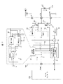
- FIG. 1 is a diagram showing a schematic configuration of the load driving device of this embodiment.
- 2 to 4 are timing charts showing the operation of the disconnection diagnosis function in this embodiment.
- the load driving device of this embodiment includes, as main components, a microcomputer 200 and a driver circuit (load driving circuit) 100 that supplies current to a solenoid 110 that is an inductive load.
- a driver circuit load driving circuit 100 that supplies current to a solenoid 110 that is an inductive load.
- one solenoid 110 and one driver circuit 100 are omitted for the sake of simplification of the drawing, but there is no limit to the number.
- the driver circuit 100 includes a high side switch element 40 and a low side switch element 50 connected in series to a battery power supply (VB).
- One end of a solenoid 110 is connected to a connection point (LOAD) between the high-side switch element 40 and the low-side switch element 50, and a current for driving the solenoid 110 is supplied.
- the other end of the solenoid 110 is connected (grounded) to a ground power supply (GND) 120 .
- the microcomputer 200 calculates, for example, the current to be supplied to the solenoid 110 required for the operation of the vehicle automatic transmission, and uses the current value as a target current value to provide the driver circuit 100 with the high-side switch element 40 and the low-side switch element.
- a PWM signal 11 for controlling the ON/OFF timing of 50 is output.
- the driver circuit 100 Upon receiving the PWM signal 11, the driver circuit 100 generates control signals 31 and 32 so that the switch control circuit 30 turns on the high side switch element 40 and turns off the low side switch element 50 when the PWM signal 11 is at high level. Then, current is supplied to the solenoid 110 from the battery power source (VB) via the high side switch element 40 .
- VB battery power source
- the control signals 31 and 32 are generated to turn off the high side switch element 40 and turn on the low side switch element 50, thereby cutting off the current supply from the battery power supply (VB).
- current is supplied from the RETURN ground power supply (GND) to the solenoid 110 via the low-side switch element 50 by the back electromotive force generated by the interruption of the current.
- the high-side switch element 40 and the low-side switch element 50 require transition time to switch from ON to OFF and from OFF to ON.
- the ON control timing is delayed so that both switch elements 40 and 50 are turned OFF, and a period (hereinafter referred to as a dead time period) is added to the control signals 31 and 32 .
- the current supplied to the solenoid 110 can be increased or decreased.
- the current to the solenoid 110 is accurately controlled.
- the current flowing through the solenoid 110 is detected and measured by the high side current monitor circuit 60 and the low side current monitor circuit 70 for each high side switch element 40 and low side switch element 50 .
- an average current calculation circuit 80 calculates an average current value (PWM cycle average current value) 81 for one cycle of the PWM signal and transfers it to the microcomputer 200. be done.
- the sampling frequency of the instantaneous current value (instantaneous current sampled value) 65 used to calculate the PWM cycle average current value 81 is several hundred Hz to several kHz of the PWM signal assumed, and several MHz to several thousand. It's on the order of double.
- a disconnection diagnosis circuit that performs disconnection diagnosis of the solenoid 110 based on the PWM signal 11 and the instantaneous current value 65 detected and measured by the high-side current monitor circuit 60 and the low-side current monitor circuit 70. 90 is installed.
- the disconnection diagnosis circuit 90 acquires a difference value (instantaneous current difference value) 21 between samples before and after the instantaneous current value 65 detected and measured by the high-side current monitor circuit 60 and the low-side current monitor circuit 70 .
- the polarity of the instantaneous current difference value 21 is assumed to be positive (positive direction) when the instantaneous current value 65 increases, and negative (minus direction) when it decreases.
- filter processing such as averaging processing is performed on the instantaneous current value 65.
- averaging processing is performed on the instantaneous current value 65.
- Conduct in advance For example, when the instantaneous current value 65 is averaged every 8 samples, the difference calculation of the current value is also performed on the average value, and the evaluation is determined.
- both the switch elements 40 and 50 are turned off, and current detection and measurement by the high side current monitor circuit 60 and the low side current monitor circuit 70 may not be stable. Therefore, during the dead time period, the current difference value (instantaneous current difference value) 21 is not acquired (masked), and processing such as excluding disconnection detection is performed.
- the value 21 is also a positive value equal to or greater than a certain value.
- the disconnection determination threshold value 22 is set near the minimum value "0" of the assumed instantaneous current difference value 21, and the instantaneous current
- a disconnection determination circuit 20 is provided for determining a disconnection when the difference value 21 becomes equal to or less than the disconnection determination threshold value 22 .
- the current of the solenoid 110 gradually decreases as shown in the above equation (2).
- the difference value 21 becomes a negative value equal to or greater than a certain value.
- the disconnection determination threshold value 22 is set below the lowest value (negatively large) of the assumed instantaneous current difference value 21, and the instantaneous If the current difference value 21 becomes equal to or less than the disconnection determination threshold value 22 (negatively large), the disconnection determination circuit 20 determines that there is a disconnection. Then, the determination output of the disconnection determination circuit 20 is transferred to the microcomputer 200 as the disconnection diagnosis result 91 of the solenoid 110 .
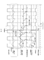
- FIG. 2 shows an example of an operation timing chart of the disconnection diagnosis function of the solenoid 110 in this embodiment.
- the processing of the signal delay difference and the dead time period is omitted from the illustration.
- the current of the solenoid 110 repeats a gradual increase when the PWM signal 11 is at a high level and a gradual decrease when the PWM signal 11 is at a low level.
- the instantaneous current difference value 21 (.DELTA.LOAD current in the figure) which is the differential) repeats a positive gradual decrease when the PWM signal 11 is at a high level and a negative gradual decrease when the PWM signal 11 is at a low level. , the current difference 21 also drops sharply.
- FIG. 2 shows a case in which disconnection occurs when the high-side switch element 40 is ON, but the disconnection determination threshold value 22 or less is set in the same state, and disconnection is immediately determined.
- FIG. 3 shows an example of another operation timing chart for disconnection diagnosis of the solenoid 110 in this embodiment.
- processing of signal delay difference and dead time period is omitted.
- the duty ratio of the PWM signal 11 changes by repeating the feedback of the average current value (PWM cycle average current value) 81 of one cycle of the PWM signal, and the current of the solenoid 110 changes. To go.
- the current of the solenoid 110 gradually increases when the PWM signal 11 is at high level, and gradually decreases when it is at low level.
- the instantaneous current difference value 21 ( ⁇ LOAD current in the figure), which is the change (differential) of the instantaneous current value 65 detected and measured by the current of the solenoid 110, gradually decreases positively when the PWM signal 11 is at high level, and decreases when it is at low level.
- the negative gradual decrease is repeated, when disconnection of the solenoid 110 occurs, the current of the solenoid 110 rapidly decreases, so the instantaneous current difference value 21 also rapidly decreases to the negative side.
- FIG. 3 shows a case in which disconnection occurs when the low-side switch element 50 is ON. ), and it is immediately determined as disconnection.
- one type of disconnection determination threshold value 22 is selected when each of the switch elements 40 and 50 is ON.
- a plurality of disconnection determination threshold values 22 may be set and switched according to the instantaneous current value 65 or the current value after the averaging process for each of a plurality of samples.
- the duty ratio of the PWM signal 11 When the duty ratio of the PWM signal 11 is low and the current of the solenoid 110 is small, the change in the gradually increasing current at the high level of the PWM signal 11 is large, so the disconnection determination threshold value 22 can be increased. On the other hand, when the duty ratio of the PWM signal 11 is high and the current of the solenoid 110 is large, the change in the gradually increasing current at the high level of the PWM signal 11 is also small. It is better to set it as low as "0" or less.
- FIG. 4 shows the disconnection diagnosis function of the solenoid 110 when the disconnection determination threshold value 22 when the high-side switch element 40 is ON is switched by switching the disconnection determination threshold value 22 according to the instantaneous current value 65 to perform the disconnection diagnosis. shows an example of an operation timing chart of .
- a disconnection determination threshold switching level is set for the instantaneous current value 65, and if the instantaneous current value 65 is less than the determination threshold switching level when the high-side switch element 40 is ON, the disconnection determination threshold 22 is set high. However, if it becomes equal to or higher than the determination threshold switching level, the disconnection determination threshold 22 is set low (in the negative direction).
- the disconnection diagnosis of the solenoid 110 makes it possible to detect disconnection of the solenoid 110 with less detection delay using a simpler method.
- the microcomputer 200 can obtain information on the presence or absence of disconnection of the solenoid 110 through the disconnection diagnosis result 91 of the solenoid 110, and when the disconnection of the solenoid 110 is detected, the device such as an automatic transmission for a vehicle can be changed to a safe state. give instructions to each place.
- FIG. 5 is a diagram showing a schematic configuration of the load driving device of this embodiment, which corresponds to a modification of the first embodiment (FIG. 1).
- the other end of the solenoid 110 connected to the connection point (LOAD) between the high side switch element 40 and the low side switch element 50 is connected (grounded) to the ground power supply (GND) 120.
- the present embodiment differs from the first embodiment in that the other end of the solenoid 110 is connected to the solenoid battery power source 130 .
- Other configurations are the same as those of the first embodiment (FIG. 1).
- the configuration of the disconnection diagnosis circuit 90 can detect disconnection of the solenoid 110 with little delay.
- one end of the solenoid 110 is connected to the solenoid battery power supply 130, and the driver receives the PWM signal 11 for controlling the current flowing through the solenoid 110 from the microcomputer 200.
- the circuit 100 generates control signals 31 and 32 to turn on the low side switch element 50 and turn off the high side switch element 40 by the switch control circuit 30 when the PWM signal 11 is at high level.
- a current path is formed through the solenoid 110 and the low-side switch element 50 to the RETURN ground power supply (GND), and current is supplied to the solenoid 110 .
- GND RETURN ground power supply
- the control signals 31 and 32 are generated to turn on the high side switch element 40 and turn off the low side switch element 50, cutting off the current path to the RETURN ground power supply (GND). Then, the current is cut off, and current is supplied from the battery power supply (VB) to the solenoid 110 via the high-side switch element 40 by the back electromotive force generated by the cut-off of the current.
- the direction of the current flowing through the solenoid 110 is opposite to that of the configuration of FIG. Only the OFF timing is replaced, and the movement of the current of the solenoid 110 is the same.
- the disconnection diagnosis circuit 90 can process the instantaneous current value 65 detected and measured by the high-side current monitor circuit 60 and the low-side current monitor circuit 70 .
- a disconnection determination threshold value 22 is set in the same manner as when the high-side switch element 40 is ON in the configuration of FIG. ) 21 becomes low, a disconnection determination circuit 20 for determining disconnection may be provided.
- the high-side switch element 40 When the PWM signal 11 is at low level, the high-side switch element 40 is turned on, and the current of the solenoid 110 gradually decreases as shown in equation (2). Similarly, a disconnection determination threshold value 22 is set, and if the difference value (instantaneous current difference value) 21 becomes lower than the threshold value 22, the disconnection determination circuit 20 may be provided to determine disconnection.
- FIG. 6 is a diagram showing a schematic configuration of the load driving device of this embodiment.
- the driver circuit 100 supplies current to the solenoid 110 by turning ON/OFF the high-side switching element 40 and the low-side switching element 50 so as to complement each other. It is a so-called synchronous rectification system.
- connection point (LOAD) of the driver circuit 100 is connected (grounded) to the ground power supply (GND) 120 as shown in FIG. ), omitting the low-side switch element 50 and performing rectification with a diode 140 installed in parallel with the solenoid 110 is also conceivable.
- the high side switch element 40 when the PWM signal 11 is at high level, the high side switch element 40 is turned on, and current is supplied from the battery power supply (VB) to the solenoid 110 via the high side switch element 40 .
- the high-side switch element 40 is turned off to cut off the current supply from the battery power supply (VB).
- a forward bias is applied to a diode 140 installed in parallel with the solenoid 110 by the electromotive force, and current is supplied from the ground power supply (GND) 120 .
- the solenoid 110 can be restarted with a short delay from the occurrence of the disconnection of the solenoid 110, as in the operation timing chart example of the disconnection diagnosis of the solenoid 110 in the first embodiment shown in FIGS. Disconnection can be detected, and when disconnection of the solenoid 110 occurs, the equipment can be quickly shifted to a safe state.
- the disconnection diagnosis circuit 90 can detect the disconnection because there is almost no change in the current of the solenoid 110 .
- the present invention is not limited to the above-described embodiments, and includes various modifications.
- the above-described embodiments have been described in detail in order to explain the present invention in an easy-to-understand manner, and are not necessarily limited to those having all the described configurations.
- it is possible to replace part of the configuration of one embodiment with the configuration of another embodiment and it is also possible to add the configuration of another embodiment to the configuration of one embodiment.
- control lines and signal lines are those that are considered necessary for explanation, and not all control lines and signal lines on the product are necessarily shown.
- PWM signal 20 disconnection determination circuit 21 instantaneous current difference value 22 disconnection determination threshold 30 switch control circuit 31 (high side switch element ON/OFF) control signal 32 (low side switch element) ON/OFF) control signal 40 High side switch element 50 Low side switch element 60 High side current monitor circuit 65 Instantaneous current value (instantaneous current sampling value) 70 Low side current monitor circuit 80 Average Current calculation circuit 81 PWM period average current value 90 disconnection diagnosis circuit 91 disconnection diagnosis result 100 driver circuit (load drive circuit) 110 solenoid 120 ground power supply (GND) 130 solenoid battery Power source 140 Diode 200 Microcontroller (microcomputer).
Landscapes
- Physics & Mathematics (AREA)
- Electromagnetism (AREA)
- Engineering & Computer Science (AREA)
- Power Engineering (AREA)
- Control Of Transmission Device (AREA)
- Electronic Switches (AREA)
- Testing Of Short-Circuits, Discontinuities, Leakage, Or Incorrect Line Connections (AREA)
Priority Applications (3)
| Application Number | Priority Date | Filing Date | Title |
|---|---|---|---|
| US18/282,585 US12451281B2 (en) | 2021-04-12 | 2022-03-04 | Load drive device and method for controlling electronic control device |
| JP2023514512A JP7526362B2 (ja) | 2021-04-12 | 2022-03-04 | 負荷駆動装置、電子制御装置の制御方法 |
| CN202280028145.5A CN117121135A (zh) | 2021-04-12 | 2022-03-04 | 负载驱动装置、电子控制装置的控制方法 |
Applications Claiming Priority (2)
| Application Number | Priority Date | Filing Date | Title |
|---|---|---|---|
| JP2021066959 | 2021-04-12 | ||
| JP2021-066959 | 2021-04-12 |
Publications (1)
| Publication Number | Publication Date |
|---|---|
| WO2022219965A1 true WO2022219965A1 (ja) | 2022-10-20 |
Family
ID=83640292
Family Applications (1)
| Application Number | Title | Priority Date | Filing Date |
|---|---|---|---|
| PCT/JP2022/009514 Ceased WO2022219965A1 (ja) | 2021-04-12 | 2022-03-04 | 負荷駆動装置、電子制御装置の制御方法 |
Country Status (4)
| Country | Link |
|---|---|
| US (1) | US12451281B2 (https=) |
| JP (1) | JP7526362B2 (https=) |
| CN (1) | CN117121135A (https=) |
| WO (1) | WO2022219965A1 (https=) |
Cited By (1)
| Publication number | Priority date | Publication date | Assignee | Title |
|---|---|---|---|---|
| WO2025027763A1 (ja) * | 2023-07-31 | 2025-02-06 | 日立Astemo株式会社 | 負荷駆動装置 |
Citations (6)
| Publication number | Priority date | Publication date | Assignee | Title |
|---|---|---|---|---|
| JPS5033542B1 (https=) * | 1969-06-13 | 1975-10-31 | ||
| JP2007157830A (ja) * | 2005-12-01 | 2007-06-21 | Toyota Motor Corp | 電磁弁の制御装置 |
| JP2008041908A (ja) * | 2006-08-04 | 2008-02-21 | Hitachi Ltd | エンジン用高圧ポンプ駆動回路 |
| JP2016131328A (ja) * | 2015-01-14 | 2016-07-21 | 株式会社デンソー | 負荷駆動装置 |
| WO2018193527A1 (ja) * | 2017-04-18 | 2018-10-25 | 三菱電機株式会社 | 過電流検出回路及び電力変換装置 |
| JP2020182151A (ja) * | 2019-04-26 | 2020-11-05 | ボッシュ株式会社 | 電子制御装置及び異常検出方法 |
Family Cites Families (4)
| Publication number | Priority date | Publication date | Assignee | Title |
|---|---|---|---|---|
| JPH07194175A (ja) | 1993-12-28 | 1995-07-28 | Nippondenso Co Ltd | リニアソレノイドの駆動装置 |
| JP5033542B2 (ja) | 2007-08-29 | 2012-09-26 | 株式会社フジクラ | 携帯情報端末 |
| JP2009089072A (ja) | 2007-09-28 | 2009-04-23 | Hitachi Ltd | 電磁負荷装置の制御装置 |
| US8055460B2 (en) * | 2009-02-20 | 2011-11-08 | GM Global Technology Operations LLC | Method and apparatus for monitoring solenoid health |
-
2022
- 2022-03-04 US US18/282,585 patent/US12451281B2/en active Active
- 2022-03-04 CN CN202280028145.5A patent/CN117121135A/zh active Pending
- 2022-03-04 WO PCT/JP2022/009514 patent/WO2022219965A1/ja not_active Ceased
- 2022-03-04 JP JP2023514512A patent/JP7526362B2/ja active Active
Patent Citations (6)
| Publication number | Priority date | Publication date | Assignee | Title |
|---|---|---|---|---|
| JPS5033542B1 (https=) * | 1969-06-13 | 1975-10-31 | ||
| JP2007157830A (ja) * | 2005-12-01 | 2007-06-21 | Toyota Motor Corp | 電磁弁の制御装置 |
| JP2008041908A (ja) * | 2006-08-04 | 2008-02-21 | Hitachi Ltd | エンジン用高圧ポンプ駆動回路 |
| JP2016131328A (ja) * | 2015-01-14 | 2016-07-21 | 株式会社デンソー | 負荷駆動装置 |
| WO2018193527A1 (ja) * | 2017-04-18 | 2018-10-25 | 三菱電機株式会社 | 過電流検出回路及び電力変換装置 |
| JP2020182151A (ja) * | 2019-04-26 | 2020-11-05 | ボッシュ株式会社 | 電子制御装置及び異常検出方法 |
Cited By (1)
| Publication number | Priority date | Publication date | Assignee | Title |
|---|---|---|---|---|
| WO2025027763A1 (ja) * | 2023-07-31 | 2025-02-06 | 日立Astemo株式会社 | 負荷駆動装置 |
Also Published As
| Publication number | Publication date |
|---|---|
| US20240161956A1 (en) | 2024-05-16 |
| JPWO2022219965A1 (https=) | 2022-10-20 |
| US12451281B2 (en) | 2025-10-21 |
| CN117121135A (zh) | 2023-11-24 |
| JP7526362B2 (ja) | 2024-07-31 |
Similar Documents
| Publication | Publication Date | Title |
|---|---|---|
| JP6400610B2 (ja) | 負荷駆動回路 | |
| JP6989697B2 (ja) | 負荷駆動装置 | |
| US8625249B2 (en) | Control apparatus for electromagnetic inductive load | |
| WO2011019038A1 (ja) | 負荷駆動制御装置及び負荷駆動制御方法 | |
| JP2011023802A (ja) | 誘導性負荷制御装置 | |
| US11990897B2 (en) | Current control device for control of supply current with low-side and high-side switch elements and duration measurement | |
| JP2008029126A (ja) | 昇圧回路、モータ駆動回路及び電動パワーステアリング制御装置 | |
| CN111722090B (zh) | 一种开路故障检测系统及检测方法 | |
| JPH10176581A (ja) | スロットル制御装置 | |
| JP2008304041A (ja) | 移動不良検出装置 | |
| WO2022219965A1 (ja) | 負荷駆動装置、電子制御装置の制御方法 | |
| JP6015586B2 (ja) | Pwm制御装置およびそのpwm制御方法 | |
| CN108292920B (zh) | 电磁负载驱动装置以及车载控制系统 | |
| US12447914B2 (en) | Vehicle-mounted control device | |
| JP2009089072A (ja) | 電磁負荷装置の制御装置 | |
| US12319211B2 (en) | Electronic control device and method for controlling electronic control device | |
| US11824528B2 (en) | Load drive device and control method of load drive device | |
| KR101194989B1 (ko) | 솔레노이드 밸브의 전자제어장치 | |
| KR101870827B1 (ko) | 가변력 솔레노이드 단락진단 장치 및 방법 | |
| CN115088185B (zh) | 用于诊断电力输入电路的故障的方法及其系统 | |
| JP2009019957A (ja) | リニアソレノイドの過電流異常検出装置 | |
| CN120103125A (zh) | 用于针对励磁电流调节识别有缺陷的半导体开关的诊断 | |
| JP2006349614A (ja) | コイル異常検出装置 | |
| KR20040021184A (ko) | 액츄에이터 전류 제어 장치 |
Legal Events
| Date | Code | Title | Description |
|---|---|---|---|
| 121 | Ep: the epo has been informed by wipo that ep was designated in this application |
Ref document number: 22787893 Country of ref document: EP Kind code of ref document: A1 |
|
| WWE | Wipo information: entry into national phase |
Ref document number: 2023514512 Country of ref document: JP |
|
| WWE | Wipo information: entry into national phase |
Ref document number: 18282585 Country of ref document: US |
|
| NENP | Non-entry into the national phase |
Ref country code: DE |
|
| 122 | Ep: pct application non-entry in european phase |
Ref document number: 22787893 Country of ref document: EP Kind code of ref document: A1 |
|
| WWG | Wipo information: grant in national office |
Ref document number: 18282585 Country of ref document: US |