WO2022219932A1 - 情報処理装置、情報処理システム、及び、推定方法 - Google Patents
情報処理装置、情報処理システム、及び、推定方法 Download PDFInfo
- Publication number
- WO2022219932A1 WO2022219932A1 PCT/JP2022/007304 JP2022007304W WO2022219932A1 WO 2022219932 A1 WO2022219932 A1 WO 2022219932A1 JP 2022007304 W JP2022007304 W JP 2022007304W WO 2022219932 A1 WO2022219932 A1 WO 2022219932A1
- Authority
- WO
- WIPO (PCT)
- Prior art keywords
- person
- face
- image
- gate
- face frame
- Prior art date
Links
- 238000000034 method Methods 0.000 title claims abstract description 70
- 230000010365 information processing Effects 0.000 title claims abstract description 34
- 238000001514 detection method Methods 0.000 claims abstract description 46
- 230000008859 change Effects 0.000 claims abstract description 9
- 238000012545 processing Methods 0.000 claims description 109
- 230000001815 facial effect Effects 0.000 claims description 4
- 238000003384 imaging method Methods 0.000 claims description 4
- 230000001360 synchronised effect Effects 0.000 claims description 4
- 230000008569 process Effects 0.000 description 42
- 230000006870 function Effects 0.000 description 37
- 238000010586 diagram Methods 0.000 description 27
- 238000004891 communication Methods 0.000 description 17
- XPFVYQJUAUNWIW-UHFFFAOYSA-N furfuryl alcohol Chemical compound OCC1=CC=CO1 XPFVYQJUAUNWIW-UHFFFAOYSA-N 0.000 description 16
- 229920000368 omega-hydroxypoly(furan-2,5-diylmethylene) polymer Polymers 0.000 description 16
- 238000009434 installation Methods 0.000 description 11
- 238000006243 chemical reaction Methods 0.000 description 10
- 238000005516 engineering process Methods 0.000 description 7
- 230000007704 transition Effects 0.000 description 7
- 230000007717 exclusion Effects 0.000 description 4
- 238000003379 elimination reaction Methods 0.000 description 3
- 238000012986 modification Methods 0.000 description 3
- 230000004048 modification Effects 0.000 description 3
- 230000008034 disappearance Effects 0.000 description 2
- 230000008030 elimination Effects 0.000 description 2
- 230000014509 gene expression Effects 0.000 description 2
- 230000010354 integration Effects 0.000 description 2
- 238000011144 upstream manufacturing Methods 0.000 description 2
- 238000012795 verification Methods 0.000 description 2
- 241001465754 Metazoa Species 0.000 description 1
- 238000013459 approach Methods 0.000 description 1
- 230000033228 biological regulation Effects 0.000 description 1
- 230000001413 cellular effect Effects 0.000 description 1
- 238000004590 computer program Methods 0.000 description 1
- 239000000470 constituent Substances 0.000 description 1
- 238000010276 construction Methods 0.000 description 1
- 230000007423 decrease Effects 0.000 description 1
- 230000007547 defect Effects 0.000 description 1
- 238000013461 design Methods 0.000 description 1
- 239000003814 drug Substances 0.000 description 1
- 230000000694 effects Effects 0.000 description 1
- 238000011156 evaluation Methods 0.000 description 1
- 238000012854 evaluation process Methods 0.000 description 1
- 230000036541 health Effects 0.000 description 1
- 230000006872 improvement Effects 0.000 description 1
- 238000010801 machine learning Methods 0.000 description 1
- 230000014759 maintenance of location Effects 0.000 description 1
- 230000007257 malfunction Effects 0.000 description 1
- 238000003672 processing method Methods 0.000 description 1
- 230000004044 response Effects 0.000 description 1
- 239000004065 semiconductor Substances 0.000 description 1
Images


Classifications
-
- G—PHYSICS
- G07—CHECKING-DEVICES
- G07B—TICKET-ISSUING APPARATUS; FARE-REGISTERING APPARATUS; FRANKING APPARATUS
- G07B15/00—Arrangements or apparatus for collecting fares, tolls or entrance fees at one or more control points
-
- G—PHYSICS
- G07—CHECKING-DEVICES
- G07C—TIME OR ATTENDANCE REGISTERS; REGISTERING OR INDICATING THE WORKING OF MACHINES; GENERATING RANDOM NUMBERS; VOTING OR LOTTERY APPARATUS; ARRANGEMENTS, SYSTEMS OR APPARATUS FOR CHECKING NOT PROVIDED FOR ELSEWHERE
- G07C9/00—Individual registration on entry or exit
- G07C9/30—Individual registration on entry or exit not involving the use of a pass
- G07C9/32—Individual registration on entry or exit not involving the use of a pass in combination with an identity check
- G07C9/37—Individual registration on entry or exit not involving the use of a pass in combination with an identity check using biometric data, e.g. fingerprints, iris scans or voice recognition
Definitions
- the present disclosure relates to an information processing device, an information processing system, and an estimation method.
- Patent Document 1 when a person obtains permission to pass through a gate using a wireless card and enters the gate from the entrance of the gate, it is determined whether or not the person has passed through the gate (or returned to the entrance of the gate). Apparatus is described for tracking wireless cards based on changes in location of wireless cards.
- this management may also be abbreviated as “transit management” or “tracking management”. There is room for improvement in the accuracy of estimating a person's position in tracking management.
- Non-limiting embodiments of the present disclosure contribute to providing an information processing device, an information processing system, and an estimation method that can improve the accuracy of estimating the position of a target that is about to pass through a specific area.
- An information processing apparatus provides a first face image area included in a first image obtained by photographing a person entering a gate from a first direction, and a detection unit for detecting a second face-image area included in a second image shot from a second direction; and a relative position between the first face-image area and the second face-image area.
- an estimating unit for estimating the position of the person at the gate based on changes in relationships.
- An information processing system provides a first image of a person entering a gate photographed from a first direction and a second image of the person photographed from a second direction different from the first direction. a first facial image area included in the first image; and a second facial image area included in the second image. and an information processing device for estimating the position of the person at the gate based on a change in the relative positional relationship between the first face image area and the second face image area; Prepare.
- an information processing device includes a first face image area included in a first image of a person entering a gate photographed from a first direction, detecting a second face-image area included in a second image photographed from a second direction different from the direction of A position of the person at the gate is estimated based on the change in the positional relationship.
- a non-limiting embodiment of the present disclosure can improve the accuracy of estimating the position of an object trying to pass through a particular region.
- FIG. 4 is a diagram showing an example of a gate according to one embodiment; A diagram showing an example of a conceptual configuration of a transit management system according to an embodiment. 1 is a block diagram showing a configuration example of a transit management system according to an embodiment; FIG. A diagram showing an example of zones defined for gates A diagram showing an example of zones defined for gates FIG. 4 is a diagram showing an example of face frame detection according to an embodiment; FIG. 4 is a diagram showing an example of detection of a person's position in one embodiment; A diagram showing an example of the relationship between the size and the center of the face frame with respect to the position of the person.
- a diagram showing a first example of transition of the magnitude of the positional difference A diagram showing a second example of the transition of the magnitude of the positional difference
- a diagram showing an example of an area defined in an image area Flowchart showing an example of transit management flow Diagram showing an example of face frame timeout processing Flowchart showing an example of FFFA multiple face frame exclusion processing Flowchart showing an example of binocular face frame position estimation processing
- a diagram showing an example of a defined area for differences in camera placement Flowchart showing an example of new face frame detection using one camera
- an authentication process to authenticate a person trying to transit (which may include, for example, a process of determining that the person is unauthenticated) and a tracking system to record the history of that person's movement. processing is performed. These processes are desirably performed early in order to secure time to perform processes that restrict the movement of people, such as recording the passage of people or opening/closing processes of gate doors.
- a camera is installed above the person and the gate (for example, on the ceiling), the camera on the ceiling photographs the person and the gate, and by analyzing the photographed image, the photographed person can be tracked. be considered.
- the installation location of the camera may be restricted depending on the structure or environment of the installation location.
- the installation cost will increase. Therefore, it may be difficult to introduce a passage control system using a camera installed on the ceiling.
- the gate it is conceivable to provide the gate with an arch-shaped or pole-shaped support extending above the gate, and install the camera on the support. Since the size in the height direction is larger than that of the gate without it, the installation location of the gate may be limited. In terms of design, it may not be preferable to provide the gate with a supporting portion.
- an image captured by a camera used for face authentication processing of a person trying to pass through the gate is used to perform tracking processing for tracking the person trying to pass through the gate, thereby performing authentication processing and tracking processing. and carry out transit control processing.
- the camera used for the authentication process is also used for the tracking process, there is no need to separately provide a device for the tracking process (for example, a camera on the ceiling or the like). Therefore, it is possible to suppress an increase in introduction cost of passage management.
- equipment such as a dedicated camera is provided for tracking processing, restrictions on the installation location are eased, so the degree of freedom of the installation location is improved and the introduction of the transit management system is facilitated.
- FIG. 1 is a diagram showing an example of a gate 10 according to this embodiment.
- FIG. 1 is a view of the gate 10 viewed from above, exemplifying how a person h enters through an entrance E1 of the gate 10 and exits through an entrance E2 of the gate 10.
- FIG. A person may enter the gate 10 shown in FIG. 1 through the entrance E2 and exit through the entrance E1.
- the gate 10 allows people to pass in both directions.
- the gate 10 has, for example, side walls V facing each other, and a passage L is formed between the side walls V to guide a person passing through the gate 10 .
- cameras 11 are provided at two positions closer to the entrances E1 and E2 than the central portion of the side wall V, for example.
- a total of four cameras 11 (11-R1, 11-R2, 11-L1, 11-L2) are provided for the two side walls V.
- the cameras 11-R1 and 11-L1 are installed, for example, on the side wall V at a position closer to the entrance E2 than the central part of the gate 10, and photograph a person entering from the entrance E1 of the gate 10 and passing through the entrance E2. Used.
- the cameras 11-R2 and 11-L2 are installed, for example, on the side wall V at a position closer to the entrance E1 than the central portion of the gate 10, and capture the image of a person entering from the entrance E2 of the gate 10 and passing through the entrance E1. Used for shooting.
- the camera 11-R1 is installed at a position where a person entering from the entrance E1 can be photographed from the right front of the person.
- the camera 11-L1 is installed, for example, at a position where a person entering from the entrance E1 can be photographed from the front left of the person.
- the camera 11-R2 is installed, for example, at a position where it is possible to photograph a person entering from the entrance E2, which is opposite to the entrance E1, from the right front of the person.
- the camera 11-L2 is installed, for example, at a position where it is possible to photograph a person entering from the entrance E2 opposite to the entrance E1 from the left front of the person.
- a person who enters the gate 10 through the entrance E1 and passes through the entrance E2 can see, for example, two cameras 11-R1 and 11-, which are installed at positions separated from each other across the passage L on the upper side of the two side walls V. Images are captured from two directions (for example, left and right directions) by L1.
- a person who passes through the gate 10 in the opposite direction that is, a person who enters the gate 10 from the entrance E2 and then passes through the entrance E1, is placed at positions separated from each other across the passage L, for example, at the top of the two side walls V. Images are taken from two directions (for example, left and right directions) by the two installed cameras 11-R2 and 11-L2.
- FIG. 1 is a configuration example in which a person can enter from both the entrance E1 and the entrance E2 of the gate 10, the present disclosure is not limited to this.
- the gate 10 may be configured such that a person can enter from one entrance (for example, entrance E1) and cannot enter from the other entrance (for example, entrance E2). If the gate 10 does not allow entry of a person through the entrance E2, the cameras 11-R2 and 11-L2 may not be provided. If the gate 10 does not allow entry of a person through the entrance E1, the cameras 11-R1 and 11-L1 may not be provided.
- the camera 11-R1 and the camera 11-L1 are used to manage the passage of a person entering from the entrance E1 and passing through the entrance E2.
- the camera 11-R1 and the camera 11-L1 may be collectively referred to as the camera 11 for convenience.
- the camera 11-R1 may be described as the right camera 11, and the image captured by the right camera 11 may be described as "right image”.
- camera 11-L1 may be referred to as left camera 11, and the image captured by left camera 11 may be referred to as a "left image.”
- a person who enters the gate 10 corresponds to a person who is subject to processing including face authentication processing.
- a person to be processed is referred to as a "subject".
- the gate 10 in FIG. 1 is an example, and the present disclosure is not limited to this.
- the gate 10 may be provided with five or more cameras 11 or three or less cameras 11 . By changing the photographing direction and/or angle of the camera 11, a person's face can be photographed in a wider range.
- the camera 11 may be provided at a position for photographing the face of a person entering the gate 10 from the front, or at a position for photographing at least a part of the face (for example, the right half or the left half of the face). good too.
- the camera 11 may be provided at a position for capturing an image in which a face frame can be detected by face frame detection, which will be described later.
- the plurality of cameras 11 may not be identical to each other.
- the plurality of cameras 11 may be configured to capture images with mutually different resolutions, angles of view, and image qualities.
- the installation position and/or shooting direction of the camera 11 may be fixed or adjustable.
- FIG. 2A is a diagram showing an example of a conceptual configuration of a transit management system according to this embodiment.
- FIG. 2B is a block diagram showing a configuration example of the passage management system according to this embodiment.
- a passage management system 1 according to the present embodiment is a system that manages the passage of people through gates 10 (for example, entrance gates, ticket gates, etc.) installed at entrances and exits of facilities such as airports, stations, and event venues. .
- gates 10 for example, entrance gates, ticket gates, etc.
- entrance/exit management of facility users is executed by face authentication.
- face authentication is used to determine whether the user is authorized to enter the facility.
- users exit the facility through a gate which user exits the facility is determined by face recognition.
- face authentication may be regarded as a concept included in "matching using a face image”.
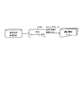
- the passage management system 1 includes, for example, the gate 10 illustrated in FIG. , a face authentication server 16, and a passage history management server 17.
- the number of gates 10 may be one or plural.
- Gates 10 are installed in facilities such as airports, train stations, and event venues. A user who is permitted to use the facility passes through the gate 10 when entering and/or exiting the facility. Also, the gate 10 is controlled so as to block the passage of persons who are not permitted to enter the facility.
- the camera 11 is provided, for example, on the side wall V of the gate 10, as shown in FIG.
- the camera 11 photographs a photographing range including a person passing through the gate 10 and the face of the person when the person is about to pass through the gate 10 .
- the photographing range of the camera 11 is a range in which the front face of a person can be photographed.
- the image captured by the camera 11 may be used for person detection processing (or person tracking processing), which will be described later, or may be used for face authentication processing, which will be described later.
- the face authentication function unit 13 performs face authentication processing on the image.
- the face authentication function section 13 has a camera control section 131 and a face matching processing section 132 .
- the camera control unit 131 controls the shooting timing of the camera 11, for example.
- the camera 11 shoots at a speed of about 5 fps (frame per second) under the control of the camera control section 131 .
- the right camera 11 and the left camera 11 may shoot simultaneously or with a difference in shooting timing within an allowable range under the control of the camera control unit 131, for example.
- the imaging timing of the right camera 11 and the imaging timing of the left camera 11 are synchronized by control of the camera control section 131, for example.
- the camera control unit 131 detects the face frame from the images (right image and/or left image) captured by the camera 11.
- the method of detecting the face frame is not particularly limited. A method of detecting a frame (face frame) surrounding a face region by detecting a boundary between the region and a region outside the face may be employed.
- the camera control unit 131 outputs information on the detected face frame (face frame information) and the captured image to the face matching processing unit 132 .
- the face matching processing unit 132 cuts out a face area included in the image based on the face frame information, and notifies the face authentication server 16 of a face matching request including information on the cut out face area.
- the face area information may be, for example, an image of the face area or information indicating feature points extracted from the image of the face area.
- a face image registered in the face authentication server 16 may be described as a registered face image.
- a registered face image may be associated with information that can uniquely identify or specify a person, such as an ID (Identification) of a registered person.
- the registered face image may be, for example, information indicating feature points extracted from the image.
- the face authentication server 16 determines whether the face of the same person as the face in the face area included in the face matching request is included in the registered face image. judge. The face authentication server 16 notifies the face matching processing unit 132 of the face matching result including the determination result, for example.
- the face matching result includes, for example, information indicating whether or not the face of the same person as the face in the face area is included in the registered face image (for example, a flag indicating "OK" or "NG");
- information for example, ID of the person associated with the registered face image may be included.
- Verification is, for example, comparing the registered face image with the face image of the person passing through the gate 10 to determine whether the registered face image registered in advance matches the face image of the person passing through the gate 10. Alternatively, it is determined whether or not the face image registered in advance and the face image of the person passing through the gate 10 are of the same person.
- authentication means for example, verifying that a person whose face image matches a pre-registered face image is the person himself/herself (in other words, that the person is permitted to pass through the gate 10). , gate 10).
- the matching process is a process of comparing feature points of registered face images that have been registered in advance with feature points extracted from the detected face area to identify the face in the image data.
- a technique using machine learning may be used.
- the matching process may be performed in the face authentication server 16, for example, but may also be performed in another device such as the gate 10, or may be distributed by a plurality of devices. .
- the face matching processing unit 132 outputs, for example, information including the matching processing result to the passage management function unit 15.
- the result of the matching process may include, for example, information about the registered face image and a matching score indicating the degree of matching of the face images obtained by the matching process.
- the information output from the face matching processing unit 132 may include, for example, face frame detection information, and the photographing time of the face photographing camera image that detected the face frame.
- the person position estimation unit 14 performs person tracking processing, for example, based on face frame information.
- the person position estimation unit 14 includes, for example, a person tracking processing unit 141 .
- the person tracking processing unit 141 estimates the position of the person with respect to the gate 10, for example, based on the face frame information. Then, the person tracking processing unit 141 determines an event that occurs to the person by tracking the estimated position of the person. For example, an event that occurs to a person includes the appearance of a new person, the tracking of a person, and the disappearance of a person. For example, the person tracking processing unit 141 determines an event based on the person's position, and tracks the person by associating the determined event with information such as the person's position and the detection time.
- the person tracking processing unit 141 outputs information on person tracking to the transit management function unit 15, for example.
- information related to person tracking includes information on the location of a person and information such as the time of detection.
- the passage management function unit 15 manages the state of the person positioned around the gate 10 by, for example, associating the information output from the face authentication function unit 13 with the information output from the person position estimation unit 14. .
- a person positioned around the gate 10 includes, for example, a person passing through the gate 10 , a person trying to pass through the gate 10 , and a person passing by the gate 10 .
- the person trying to pass through the gate 10 is not limited to a person who is permitted to pass through the gate 10 (for example, a person whose face image has been registered in the face authentication server 16). It may be a person who is not registered with the authentication server 16 but who tries to pass.
- a person passing through the gate 10 is, for example, a person who is not going to pass through the gate 10 but is passing through the photographing range of the camera 11, or who is not going to pass through the gate 10 but is within the photographing range. It is a person who is entering into Also, the state of a person may be, for example, a state related to the movement of the person, such as whether the person is moving or stationary, and the direction of movement when the person is moving.
- the passage management function unit 15 has, for example, a passage management state transition processing unit 151, a history management unit 152, and a history database (DB) 153.
- the passage management state transition processing unit 151 transmits to the gate 10, for example, control information regarding control of the gate 10 when a person permitted to pass through the gate 10 passes through in the person passage management processing. Also, the passage management state transition processing unit 151 transmits to the gate 10 control information regarding control of the gate 10 when, for example, a person who is not permitted to pass through the gate 10 tries to pass through.
- the history management unit 152 stores and manages, for example, information indicating the history of a person who has passed through the gate 10 (passage history information).
- the history management unit 152 also stores the passage history information in the history DB 153 and transmits the passage history information to the passage history management server 17, for example.
- the history management unit 152 may manage local passage history information for each station (or one ticket gate).
- the passage history management server 17 stores and manages, for example, information (passage history information) indicating the history of a person who has passed through the gate 10 .
- the passage history management server 17 may manage passage history information of multiple gates 10 .
- the passage history information of the gates 10 provided at each of the multiple entrances may be collected and managed by the passage history management server 17 .
- the passage history information of each of the gates 10 installed at the ticket gates of a plurality of stations may be collected and managed by the passage history management server 17 .
- the passage management function unit 15 may output, for example, information (passage management information) related to passage management to a display device (not shown).
- the passage management information may include information output from the face authentication function unit 13 and information output from the person position estimation unit 14, for example.
- the display device may display, for example, the state of a person (for example, the person's face recognition result and movement direction). For example, the display device may display a right image and/or a left image and superimpose the detected face frame on the right image and/or the left image.
- the display device may display information about the person (for example, the person's ID) obtained by face authentication, superimposed on the right image and/or the left image.
- the face authentication function unit 13 described above may operate, for example, in synchronization with or asynchronously with the passage management function unit 15. In the asynchronous case, for example, the face authentication function unit 13 may operate when the camera control unit 131 detects a face frame.
- the above-described three configurations of the face authentication function unit 13, the person position estimation unit 14, and the passage management function unit 15 may each have the form of one information processing device (for example, a server device), Two or more of the three may be included in one information processing device.
- the face authentication function unit 13 may have the form of one information processing device, and the person position estimation unit 14 and the passage management function unit 15 may be included in one information processing device.
- At least one of the face authentication function unit 13 , the person position estimation unit 14 , and the passage control function unit 15 having the form of an information processing device may be included in the gate 10 .
- the information processing apparatus described above may include a processor, a memory, and an input/output interface used to transmit various types of information.
- a processor is a computing device such as a CPU (Central Processing Unit) or a GPU (Graphics Processing Unit).
- the memory is a storage device implemented using RAM (Random Access Memory), ROM (Read Only Memory), or the like.
- the processor, memory, and input/output interface are connected to a bus and exchange various information via the bus.
- the processor for example, reads programs and data stored in the ROM onto the RAM and executes processing, thereby realizing the functions of the configuration included in the information processing apparatus.
- the above-described person position estimation unit 14 and passage management function unit 15 may, for example, define areas (or zones) in the gate 10, and perform person detection and passage management based on the defined zones.
- areas or zones
- An example of the zones defined in gate 10 is described below.
- 3A and 3B are diagrams showing examples of zones defined for the gate 10.
- FIG. FIGS. 3A and 3B show examples of multiple zones when the gate 10 is viewed from above.
- 3A and 3B show an example in which the side wall V of the gate 10 forming the passage L extends along the vertical direction of the paper surface.
- the upstream side along a specific approach direction corresponds to the entrance
- the downstream side corresponds to the exit.
- FIG. 3A shows an example of a zone defined when a person enters from the entrance E2 at a gate 10 that allows a person to enter from both the entrances E1 and E2.
- FIG. 3B shows an example of a zone defined when a person enters through the entrance E1.
- the passage management function defines, for example, the entrance E1 as the "north side" and the entrance E2 as the "south side.”
- references to north and south do not limit the placement of the gates 10 along a geographic north-south direction.
- references to north and south do not limit the placement of the gates 10 along a geographic north-south direction.
- the passage L of the gate 10 is located along a direction different from the north-south direction, or even if the passage includes a curved line, one may be defined as the "north side” and the other as the “south side.” .
- FIG. 3A shows an example of a zone defined when a person enters from the entrance E2.
- "Zone outside-S" (south zone outside area), "Zone A” (zone A), “Zone B” (zone B), and "Zone C” (zone C) Defined.
- FIG. 3B shows an example of a zone defined when a person enters from the entrance E1.
- "Zone outside-N" noden zone outside area
- "Zone A” zone A
- "Zone B” zone B
- "Zone C” zone C
- the boundary between the south outside zone area and zone A may be called, for example, the "face authentication start line".
- Face authentication start line is used, for example, to determine whether to start face authentication processing. For example, when a person crosses the "face authentication start line” and enters the gate 10, the face authentication process is started. For example, a face matching request is issued from face frame information, a matching result (face authentication ID) and person detection information are linked, and tracking of a person is started. Note that the "face authentication start line” may be referred to as "A line”.
- the "face authentication start line” may be provided outside the gate 10 (for example, upstream along the route of the gate 10). Also, the “face authentication start line” is not limited to one line segment, and may have a plurality of line segments such as a U-shape, for example. Note that the shape having a plurality of line segments is not limited to a shape corresponding to a part of the sides of a rectangle such as a U-shape, and may be a shape corresponding to a part of the sides of another polygonal shape. may Alternatively, the "face authentication start line” may have an arc or a shape in which straight lines and curved lines are mixed.
- face authentication start line has a plurality of line segments and/or arcs
- face authentication processing can be started.
- zone A The boundary between zone A and zone B may be called, for example, the "door closing limit line".
- the "door closing limit line” indicates, for example, the position where the exit side gate door can be closed in time in response to the door closing instruction by the time the person passes the exit side gate door position.
- the “door closing limit line” is, for example, the maximum speed assumed as the speed at which a person passes through the gate 10 (for example, 6 km / h, hereinafter referred to as “maximum passable speed”), and the speed until the gate door is physically closed. is determined in consideration of the time (for example, 0.5 seconds) required for For example, the "door closing limit line” is the distance equivalent to "maximum passage speed" x "time required to physically close the gate” from the physical position of the gate ("gate door position"). , is set to the front.
- closed door limit line may also be referred to as "unauthorized intrusion detection line” or "B line”.
- Zone B The boundary between Zone B and Zone C may be referred to as the "exit line".
- the “exit line” indicates, for example, the position where it is determined that the person has exited the gate 10.
- the "exit line” may be provided outside the gate 10, for example, like the "face authentication start line” described above.
- the "exit line” is not limited to one line segment, and may have a plurality of line segments such as a U-shape. Alternatively, the “exit line” may have an arc. Note that the "exit line” may also be called, for example, the "Z line”.
- the gate door position may be just a passing point, and in this case, the gate door position may be different from or the same as the logically set "exit line".
- the "gate door position" and the "exit line” may be set to be the same.
- the "exit line” may correspond to the "charging line”.
- a person who enters the gate 10 crosses the charging line (for example, when entering from zone B to zone C), the person is charged. In other words, when the person has not crossed the charging line (for example, when the person has not entered zone C), the person is not charged.
- the charging line it is possible to avoid the error of charging a person who has entered the gate 10 but turned back before crossing the charging line.
- the "charging line” corresponds to the "Z line" ("exit line"), but for example, the “charging line” may correspond to the "B line”.
- the position of a person By detecting the position of a person with respect to the zones described above, for example, movement between zones is estimated.
- the position of a person is estimated using images captured by the right camera 11 and the left camera 11, for example.
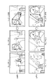
- FIG. 4 is a diagram showing an example of face frame detection according to the present embodiment.
- FIG. 4 shows right images R 1 and R 2 captured by the right camera 11 and left images L 1 and L 2 captured by the left camera 11 .
- the right image R1 and the left image L1 are images captured at the same time t1 , for example.
- the right image R2 and the left image L2 are images captured at the same time t2, for example.
- Time t2 is a time later than time t1.
- the person's position at time t2 is closer to the charge line at gate 10 than the person's position at time t1.
- the right image R 1 , right image R 2 , left image L 1 , and left image L 2 include, for example, a person passing through the gate 10 and a frame (face frame) surrounding the person's face.
- the face frame of the left image L2 is closer to the left end of the image area than the face frame of the left image L1.
- the face frame of the right image R2 is closer to the right end of the image area than the face frame of the right image R1 .
- the horizontal direction in the image area is defined as the horizontal direction or the X-axis direction.
- FIG. 5A is a diagram showing an example of detecting the position of a person according to this embodiment.
- FIG. 5A shows two images based on the image shown in FIG. 4 and extracted images obtained by extracting face frames from the two images.
- Image T1 in FIG. 5A shows an example of comparison of the positional relationship of the face frame between left image L1 and right image R1 at time t1 shown in FIG.
- the right side of image T1 shows the partial area including the face frame of left image L1 shown in FIG. 4
- the left side of image T1 shows the part containing the face frame of right image R1 shown in FIG. indicate the area.
- the face frame of the left image L1 exists to the right of the face frame of the right image R1 .
- Image T2 in FIG . 5A shows an example of comparison of the positional relationship of the face frame between left image L2 and right image R2 at time t2 shown in FIG .
- the right side of image T2 shows the partial region including the face frame of right image R2 shown in FIG . 4
- the left side of image T2 shows the portion containing the face frame of left image L2 shown in FIG . indicate the area.
- the face frame of the left image L2 exists to the left of the face frame of the right image R2 .
- the position of the person is estimated based on the difference between the position of the face frame in the right image and the position of the face frame in the left image.
- the position of the face frame is represented by a representative point of the face frame.
- An example in which the representative point is the center point of the face frame will be described below. Since the center point of the face frame does not change significantly even if the size of the face is different, by using the center point of the face frame as a representative point, even if the size of the person's face varies, position can be stably estimated. However, the present disclosure is not limited to this. If the face frame is rectangular, the representative points may be points indicating the corners of the rectangle. If the face frame is elliptical, the representative point may be the focal point of the ellipse.
- the distance between the point P R indicating the center of the face frame of the right image and the point P L indicating the center of the face frame of the left image is, for example, the point P R may be represented by the horizontal component (along the X-axis) of a vector from point P R to point P L starting at .
- the distance between the face frame point P R of the right image and the face frame point P L of the left image may be referred to as a horizontal coordinate position difference or a position difference.
- point P R is to the left of point P L , so the horizontal component of the vector has a positive value. Also, in the extracted image U2 , since the point P R is to the right of the point P L , the horizontal component of the vector has a negative value.
- FIG. 5B is a diagram showing an example of the relationship between the size of the face frame and the center with respect to the position of the person.
- FIG. 5B shows the positional relationship of the center of the face frame, the size of the face frame, and the vector defined by the center of the face frame for three different distances from the charging line of the gate 10 (far, middle, near). is shown in relation to the direction of
- the center of the face frame of the right image is It exists on the left side, and the center of the face frame of the left image exists on the right side.
- the center of the face frame of the right image moves rightward, and the center of the face frame of the left image moves leftward. Therefore, the direction of the vector from the center of the face frame of the right image to the center of the face frame of the left image changes from the positive direction to the negative direction.
- the polarity of the distance in the horizontal direction to the center of the face frame of the left image is reversed.
- a person's position is estimated by comparing the position difference with a threshold. For example, if the positional difference is equal to or less than the threshold, it is determined that the person is at a position beyond the charging line.
- the position difference when a person passes through a gate, the position difference gradually decreases from a positive value to a negative value.
- the positional difference changes from a positive value to a negative value polarity is determined
- the positional relationship between the face frame of the left image and the face frame of the right image is reversed.
- the face frame of the left image and the face frame of the right image cross each other with the positional difference of zero as the boundary. Therefore, when the positional difference becomes zero, it may be determined that the person exists at a position beyond the charging line.
- the angle of view of the camera, the size of the gate, and the position of the charge line are determined so that the position of the point (cross point) where the face frame of the left image and the face frame of the right image intersect coincides with the charge line.
- the position of the point (cross point) where the face frame of the left image and the face frame of the right image cross is not easily affected by the size of the face frame (that is, the size of the person's face). If the billing line corresponds, the judgment accuracy of the billing line can be improved.
- the center of the face frame is used and the difference between the horizontal coordinates of the center is calculated for estimation, the influence of the difference in the size of the face frame due to the size of the face and/or the height can be avoided, and the estimation accuracy can be improved. can be suppressed or avoided.
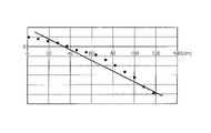
- FIG. 6A is a diagram showing a first example of changes in the magnitude of the position difference.
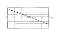
- FIG. 6B is a diagram illustrating a second example of transition of the magnitude of the positional difference.
- 6A and 6B differ from each other in the arrangement of the right camera 11 and the left camera 11.
- FIG. The horizontal axes in FIGS. 6A and 6B indicate the distance along the passage from the position outside the entrance of the gate 10 and where face authentication is possible, and the vertical axis indicates the magnitude of the positional difference. . Note that when the positional difference is a positive value, the center of the face frame of the left image exists to the right of the face frame of the right image. Further, when the positional difference is a negative value, the face frame of the right image exists to the right of the face frame of the left image.
- the position difference takes zero at a certain position. Further, when comparing FIGS. 6A and 6B, the position where the positional difference becomes zero may differ depending on the arrangement of the camera 11. FIG.
- the position where the positional difference is zero can be associated with the charging line.
- the position where the positional difference is zero is defined by the arrangement of the cameras, the position of the billing line can be adjusted appropriately.
- FIG. 7 is a diagram showing an example of the flow of person tracking processing based on the face frame according to the present embodiment.
- the face frame position determination library 201 is, for example, a library that has a function of acquiring face frame detection information and detecting the position of a person corresponding to the face frame.
- the face frame position determination library 201 detects the position of the person from the position of the face frame in the image, for example, by the method described above.
- the face frame position determination library 201 may be given a new person ID.
- the face frame position determination library 201 Continue tracking the person based on the face frame detection information.
- the face frame position determination library 201 outputs person tracking information to the passage management library 202, for example.
- Person tracking information may include, for example, a person ID that identifies a person.
- the person tracking information may also include, for example, information about the location of a person (eg, occurrence of a person, tracking of a person, disappearance of a person, etc.).
- the person tracking information may be compatible between the face frame position determination library 201 and the passage management library 202, for example.
- the passage management library 202 has a function of identifying passage management events at the gate 10 based on, for example, person tracking information.
- the passage management library 202 also outputs, for example, passage management events to the passage management processing unit 203 .
- a passage management event is, for example, an event indicating that a person has moved between zones in a plurality of zones shown in FIGS. 3A and 3B, or an event indicating that a person has crossed a line defining between zones. , an event indicating that a person has appeared in a certain zone, and an event indicating that a person has disappeared in a certain zone.
- the passage management processing unit 203 outputs passage information indicating whether or not a person has passed through the gate 10, or whether or not a person has passed through a charging line, for example, based on a passage management event.
- the result output unit 204 outputs, for example, the result of tracking the person indicated by the passage information. For example, the result output unit 204 displays the results on the display.
- FIG. 8 is a diagram showing an example of areas defined in the image area.
- FIG. 8 shows an image area where the upper left is the origin (0, 0), the horizontal (X-axis) length of the frame is "XframeMax", and the vertical length is "YframeMax”. .
- FIG. 8 also shows, by way of example, a face frame whose one side length is wf and whose upper left coordinates are (Xf, Yf), and the center of the face frame (Xc, Yc).
- the information indicating the face frame may be represented by, for example, X, Y coordinates representing the upper left point of the face frame and wf representing one side of the face frame, as shown in FIG.
- three areas may be defined in the image area of the left image.
- the right area represents the initial appearance area (First Face Frame Area (hereinafter, FFFA)
- the central area represents the middle area (Middle Face Frame Area (hereinafter, MFFA)).
- the left area represents a Passed Face Frame Area (hereinafter referred to as PFFA).
- FIG. 8 shows three areas in the image area of the left image
- the left and right of the three areas may be reversed in the image area of the right image.
- the left area may represent FFFA and the right area may represent PFFA.
- the sizes and positions of the three areas in FIG. 8 are exemplary, and the present disclosure is not limited thereto. The size and position of the three areas may differ from camera 11 to camera 11 .
- the face frame position determination library 201 may determine which of the three areas of the image region the center of the detected face frame is included based on the face frame detection information.
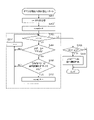
- FIG. 9 is a flow chart showing an example of the flow of passage management.
- the flow shown in FIG. 9 may be started, for example, each time information about an image captured by the camera 11 is obtained.
- the face authentication function unit 13 acquires information on the image captured by the camera 11 and performs processing for detecting a face frame from the image (S101).
- the image information acquired from the camera 11 includes information for identifying the camera that took the image (hereinafter referred to as camera ID), information for identifying the captured frame (hereinafter referred to as frame ID), date and time of image capture, and the like. may be included.
- the face authentication function unit 13 generates information on the detected face frame, and outputs the information on the face frame and the information on the image to the person position estimation unit 14 .
- the information on the face frame may include information indicating the position and size of the face frame. Note that if the face frame is not detected from the image, the processes from S102 onward need not be executed.
- the human position estimation unit 14 performs subsequent processing based on the face frame position determination library 201.
- the person position estimation unit 14 performs face frame timeout processing (S102).
- face frame timeout processing the face frame detection information held in the face frame information list is timed out based on the elapsed time from the timing when the face frame detection information is first acquired. Note that the face frame timeout processing will be described later.
- the person position estimation unit 14 performs face frame detection information generation processing (S103).
- face frame detection information including information on the camera ID, frame ID, shooting date and time, and coordinates of the detected face frame is generated.
- the face frame detection information may include information about the area where the face frame is detected.
- the area where the face frame is detected is determined, for example, based on the definition of the area as illustrated in FIG.
- the definition of the area may be included in the face frame appearance area definition information. Note that when a plurality of face frames are detected in one image, the face frame detection information generation process is executed for each of the plurality of face frames. Note that the face frame detection information generation process will be described later.
- the human position estimation unit 14 performs FFFA multiple face frame elimination processing (S104).
- FFFA multiple face frame elimination processing it is determined whether or not a plurality of face frames exist in FFFA, and if a plurality of face frames exist in FFFA, subsequent processing is not executed. The FFFA multiple face frame elimination process will be described later.
- the person position estimation unit 14 performs time-series face frame detection evaluation processing (S105).
- the face frame detection information is evaluated by comparing the latest information of the face frame detection table and the immediately previous information. For example, when the face frame indicated by the face frame detection information is the face frame of a newly appearing person, a new ID is assigned to the person.
- the human position estimation unit 14 performs a binocular face frame position estimation process (S106). Person tracking information is generated by the binocular face frame position estimation processing. Note that the two-lens method face frame position estimation processing will be described later.
- the person position estimation unit 14 outputs the person tracking data to the passage management function unit 15 (S107). Then, the flow of FIG. 9 ends, and the passage management function unit 15 performs passage management processing based on the passage management library.
- the detection position of the face frame is determined. For example, in each of the right image and the left image, it is determined which area defined in the image region includes the position of the detected face frame.
- the center of the extracted face frame is calculated, and it is determined in which area of FFFA, MFFA, and PFFA the center exists.
- the center of the face frame does not exist in any area, the information on the face frame is discarded.
- the center of the face frame does not exist in any area is because there is a high possibility that it is the face frame of an unauthorized person.
- the minimum face frame size set in the existing area is compared with the size of the face frame. Then, when the size of the face frame is smaller than the minimum face frame size, the information of the face frame is discarded.
- the size of the face frame is smaller than the minimum face frame size, it means that the face of a person who is unlikely to enter the gate 10, or the face drawn on the clothes or the poster is detected, or the pattern that is not the face is detected. This is because there is a high possibility of the face frame of an unauthorized person, such as erroneously detecting a face.
- the determination of the area in which the face frame exists and the comparison with the minimum face frame size set for the area in which the face frame exists are performed by determining the size of the face frame. executed for each.
- a list for time-series determination processing may be generated from the face frame detection information.
- the generated list may be called a face frame information list (or Queue structure list).
- the face frame information list may include information on the center coordinates of the face frame and the appearance area in the image area.
- FIG. 10 is a diagram illustrating an example of face frame timeout processing.
- the face frame to be determined is determined from the time when the face frame to be determined is first detected, for example, the time when the face frame to be determined first appears and a new ID is assigned. is compared with the time limit for holding the face frame (face frame holding time limit).
- face frame holding time limit is a predetermined threshold value and is held in a storage unit or the like.
- the face frame information is deleted from the face frame information list.
- FIG. 9 shows an example in which face frame timeout processing is executed before face frame detection information generation processing, but the present disclosure is not limited to this.
- the face frame timeout process it may be constantly checked whether or not timeout has occurred in the face frame information.
- FIG. 11 is a flowchart showing an example of FFFA multiple face frame exclusion processing. For example, the flow shown in FIG. 11 is started after S103 shown in FIG.
- the human position estimation unit 14 sets the variable i to the number of detected face frames in initial settings (S201). Note that i in FIG. 11 is an integer of 1 or more. In the following description, the number of detected face frames is N (N is an integer equal to or greater than 1). In this case, the N detected face frames are expressed as face frame [1] to face frame [N].
- the human position estimation unit 14 sets the variable "count” to 0 (S202).
- the human position estimation unit 14 determines whether i is greater than 0 (S203).
- the human position estimation unit 14 determines whether or not the face frame [i] is detected within FFFA (S204).
- the human position estimation unit 14 determines whether the size of the face frame [i] is equal to or larger than a predetermined size (S205).
- the predetermined size may be, for example, the size of a face frame with which face authentication can be started, or a size defined based on the size of the face frame with which face authentication can be started.
- the person position estimation unit 14 adds 1 to count (S206).
- the human position estimation unit 14 subtracts 1 from i (S207). Then, the process of S203 is executed.
- the human position estimation unit 14 subtracts 1 from i (S207). Then, the process of S203 is executed.
- the human position estimation unit 14 determines whether count is 2 or more. Determine (S208).
- the human position estimation unit 14 detects the face corresponding to the face frame in the FFFA.
- the frame information is deleted (S209). Then, the flow shown in FIG. 11 ends.
- the human position estimation unit 14 does not delete the face frame information. , the process may end.
- face authentication processing is not executed for each of the detected face frames. If face authentication processing is not executed for each of the detected face frames, the face frame information corresponding to the face frames detected by FFFA may be deleted. Also, in this case, since face authentication processing cannot be executed, error processing is executed. For example, the output control process of the gate device may be instructed via an audio output device and/or a display device to present a warning message to a person attempting to pass through the gate device.
- FIG. 12 is a flow chart showing an example of a two-lens method face frame position estimation process. For example, the flow shown in FIG. 12 is started after S105 shown in FIG.
- the person position estimation unit 14 determines whether or not a face frame exists in the face frame information list (S301).
- the person position estimation unit 14 determines the shooting time when the left image was shot by the left camera 11 and the right image was shot by the right camera 11. It is determined whether or not the difference from the captured time is within the allowable range (S302). In other words, in S302, it is determined whether the shooting times of the left image and the shooting time of the right image are at the same time, almost at the same time, or have an unacceptable difference. In other words, it is determined whether or not the shooting time of the left image and the shooting time of the right image are synchronized.
- the human position estimation unit 14 records a synchronization error in the log (S306).
- the human position estimation unit 14 calculates the difference between the X coordinate of the center of the face frame of the left image and the X coordinate of the center of the face frame of the right image. is calculated (S303).
- the difference between the X coordinates of the center of the face frame may hereinafter be referred to as a "central coordinate difference value”.
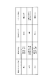
- the human position estimation unit 14 converts the calculated difference into distance information (S304).
- a conversion table may be used for this conversion. An example of the conversion table will be described later.
- the human position estimation unit 14 stores the converted result (S305). Then the flow ends.
- the human position estimation unit 14 When there is no detected face frame (NO in S301), or after recording a synchronization error (after S306), the human position estimation unit 14 outputs a result indicating that position estimation has not been performed. Store (S307). For example, information indicating "no double-lens determination" may be set in the result storage area. Then the flow ends.
- the central coordinate difference value and the estimated position where the target person exists are associated and recorded.
- the numerical information stored in the conversion table may be recorded in units of pixels (for example, in units of 1 pixel).
- the difference value may have a negative number.
- the estimated position where the target person exists may be represented by the distance from the reference point provided on the gate 10, or by the two-dimensional coordinates (eg, X coordinate and Y coordinate) from the reference point. may be represented.
- the conversion table may be developed on-memory, for example, to speed up processing related to passage management.
- a conversion table may be provided for each direction, for example.
- the conversion table may be created when the gate 10 is installed, or may be provided externally.
- the center of the face frame showing the area of the face in the right image obtained by photographing the person's face from the right front of the person entering through the entrance of the gate 10, and the left image obtained by photographing the person's face from the left front.
- the center of the face frame in the image is determined, and the position of the person in the gate 10 is estimated based on the change in the positional relationship between the center of the face frame in the right image and the center of the face frame in the left image.
- passage management processing including authentication processing and tracking processing is performed by performing tracking processing using an image captured by a camera used for face authentication processing.
- the camera used for authentication processing can be used for tracking processing without providing a device for tracking processing (for example, a camera on the ceiling, etc.).
- a passage management system can be introduced without limiting the location.
- the position of a person in order to estimate the position of a person based on the distance between the center of the face frame obtained from each of the left image and the right image, between the right camera 11 and the left camera 11, Even if there are differences in installation position, angle of view, image quality, and resolution, estimation can be performed.
- a stereo camera uses the parallax of both cameras to measure the distance to the subject. Therefore, in the stereo camera, it is necessary to strictly adjust the angles of both cameras, and control processing dedicated to the stereo camera is required.
- the position is estimated using the positional relationship of the face frame detected in the face authentication process, so the position can be estimated more easily than the stereo camera method without strictly adjusting the camera. .
- FIG. 1 shows an example in which the distance from the entrance E1 of the gate 10 to the right camera 11 (camera 11-R1) and the distance from the entrance E1 to the left camera 11 (camera 11-L1) are equal, but the present disclosure is not limited to this.
- one of the right camera 11 and the left camera 11 may be installed at a position closer to the entrance E1 of the gate 10 than the other. That is, in this case, since there is a difference between the installation positions of the right camera 11 and the left camera 11 with respect to the entrance E1 of the gate 10, there is a front-rear difference between the photographing range of the right image and the photographing range of the left image. .
- the left camera 11 when the left camera 11 is provided at a position closer to the entrance E1 than the right camera 11, when the face frames of the left image and the right image are compared, the face frame in the left image is larger than the face frame in the right image. There is a high possibility that the face frame will be outside the image area first, and the face frame will not be detected. In such a case, the area defined as the image area should be changed.
- a case where the left camera 11 is provided closer to the entrance E1 than the right camera 11 will be described below as an example.
- FIG. 13 is a diagram showing an example of prescribed areas for differences in camera placement.
- FIG. 13 shows images captured by the right camera 11 and left camera 11 at two points in time, face frames detected in each image, and defined areas in each image.
- Each image in FIG. 13 includes person A entering the gate 10 and person B entering the gate 10 from behind person A.
- the face frame of the person A in the left image is outside the image area before the face frame of the person A in the right image. go off to
- the face frame of person A in the left image is out of the image area, the face frame of person B in the left image and the face frame of person A in the right image are the same person. may be erroneously determined. Therefore, as shown in FIG. 13, the PFFA in the image of the right camera 11 is set narrower in the horizontal direction than the PFFA in the image of the left camera 11 . With this setting, for example, the timing at which the center of the face frame deviates from the PFFA can be aligned between the left image and the right image.
- ⁇ Control example 1 when an image cannot be acquired from one camera> there may be a case where the face frame cannot be detected in an image captured by one of the two cameras.
- the face frame detection process fails in the image captured by one of the cameras, or if a defect occurs in the shooting of one camera (for example, camera failure, temporary malfunction).
- passage management is performed based on the face frame detected in the image captured by the other camera when the face frame cannot be detected in the image captured by one of the two cameras.
- a processing method performed by an image captured by one camera may be referred to as a single-lens method.
- the position of the person is calculated based on the amount of movement of the face frame in the right image. may be estimated.
- this person position estimation processing for example, when a person who newly passes through the gate 10 appears in time series, the face frame of the person is detected. An example of detecting a face frame of a new person will be described below.
- FIG. 14 is a flowchart showing an example of new face frame detection using one camera. The flow shown in FIG. 14 is executed, for example, when information about an image captured by one of the right camera 11 and the left camera 11 is acquired and information about an image is not acquired from the other, or when the right camera 11 and the left camera 11 may be executed if any one of them fails to shoot.
- the face authentication function unit 13 acquires information on the image captured by the camera 11 and performs processing to detect the face frame from the image (S401).
- the person position estimation unit 14 determines whether or not the size of the face frame is equal to or larger than the specified size (S402).
- the person position estimation unit 14 performs same person determination processing (S403). For example, the person position estimating unit 14 determines whether or not the same person as the person with the detected face frame exists among the people with the face frames shown in the past face frame information list. For example, this determination may be performed by comparing respective feature points, similar to the face recognition process.
- the person position estimation unit 14 determines whether or not they are the same person (S404).
- the person position estimation unit 14 determines whether the center position of the detected face frame is included in the new appearance zone (eg, FFFA) (S405).
- the person position estimation unit 14 determines that the detected face frame is the face frame of the newly appearing person, Information on the face frame is registered (S406). Then the flow ends.
- the person corresponding to the detected face frame may be determined that the person corresponding to the detected face frame is different from the persons corresponding to the face frames detected so far, and that the face frame is a new person. If it is within the zone, it is recognized as the face frame of a new person. For example, information may be registered in a face frame tracking management table. In this case, a face matching request may be notified.
- the human position estimation unit 14 detects It is determined that the face frame obtained is an unmanaged face frame (S407). Then the flow ends.
- the person position estimation unit 14 executes the same person tracking process (S408). Then the flow ends.
- the same person determination process is not particularly limited. For example, it may be determined whether or not the person is the same person based on the amount of movement of the face frame. For example, a predetermined range of movement amount set based on the shooting interval (the range in which the person can move with respect to the shooting interval (eg, 60 msec)) is compared with the amount of movement of the face frame between the two images, If the amount of movement of the face frame is within a predetermined range, it may be determined that they are the same person.
- a predetermined range of movement amount set based on the shooting interval the range in which the person can move with respect to the shooting interval (eg, 60 msec)
- the amount of movement of the face frame is within a predetermined range, it may be determined that they are the same person.
- FIG. 15 is a flow chart showing an example of the charge line crossing determination using one camera.
- the flow shown in FIG. 15 is, for example, a case in which information about an image captured by one of the right camera 11 and the left camera 11 is acquired and no image information is acquired from the other, or It may be executed when one of them cannot shoot.
- the human position estimation unit 14 calculates the center position of the face frame (S501).
- the person position estimating unit 14 determines whether or not the center position of the face frame exists within the charging zone (eg, PFFA) (S502).
- the human position estimation unit 14 may end the process.
- the person position estimation unit 14 determines whether the initial appearance of the face frame is in a zone different from the new appearance zone (eg, FFFA). (S503). For example, among the face frame information indicating that the person is the same as the face frame whose center position is in the billing zone, the information of the first detected face frame is referred to, and the zone in which the referenced face frame is detected is a newly appearing zone.
- FFFA new appearance zone
- the determination result indicating that the person is not charged may be recorded.
- the person position estimation unit 14 determines that the size of the face frame is the threshold defined in the billing zone. It is determined whether or not it is equal to or larger than the face frame size (S504).
- the human position estimation unit 14 may end the process.
- human position estimation unit 14 determines whether the size of the face frame is increasing ( S505). For example, the person position estimating unit 14 refers to the face frame information indicating that the person is the same as the face frame to be determined, and determines whether the size of the face frame increases as the shooting time of the image progresses. You can judge whether
- the person position estimating unit 14 may end because the person is not charged. Note that, in this case, a determination result indicating that the charge has not been made may be recorded. Then, if the same determination result continues for the person for a certain period of time, it means that the person has stayed inside the gate 10 for a certain period of time, so a warning may be presented from the gate 10. .
- the person position estimation unit 14 confirms that the person has entered a charging zone (for example, zone C) at the gate 10 (S506). ). The person position estimation unit 14 notifies the determined result to the server (for example, the face authentication server 16 and/or the passage history management server 17 in FIG. 2A), so that the person is charged. Then the flow ends.
- a charging zone for example, zone C
- the server for example, the face authentication server 16 and/or the passage history management server 17 in FIG. 2A
- each zone is provided with a threshold for the size of the face frame, and if the center position of the face frame belongs to each zone and the size of the face frame exceeds the threshold of the zone to which it belongs, It may be determined that the face frame is located in the zone to which it belongs. This determination is performed in order from PFFA, which has the largest face frame size, to MFFA, and then to FFFA. Which zone it belongs to can be determined appropriately.
- the size of the face frame exceeds the threshold associated with PFFA. If so, it is determined that the face frame belongs to PFFA, omitting the determination of whether the size of the face frame exceeds the threshold associated with MFFA. If the size of the face frame is equal to or less than the threshold associated with PFFA, the face frame is determined to belong to MFFA if the size of the face frame exceeds the threshold associated with MFFA. do.
- the center position of the face frame belongs to both MFFA and FFFA
- the size of the face frame is the largest in PFFA and the smallest in FFFA, so the threshold value associated with each zone may be a value corresponding to this size relationship. However, other values may be employed, such as setting the same threshold value associated with all zones.
- the billing line crossing determination (single-lens system) using one camera is performed. I used to go there, but it's not limited to this.
- the one-lens system may be used. In this case, charging is performed when a person passes the charging line in both methods, and charging is not performed when a person does not pass the charging line in either method. can be determined.
- billing is performed when the billing line is passed by either method, billing can be reliably performed even if the determination is erroneous in either method.
- only the single eye system may be used.
- the present disclosure is not limited to this.
- the present disclosure may be applied to a case where there is no side wall of the passageway and a regulation portion (for example, a door) that regulates the passage of a person.
- the present disclosure may be applied as long as it is a moving route from a certain zone to another zone where a person is permitted to enter according to authentication processing.
- a camera that captures the face of a person passing through the movement route may be installed, for example, on a support or the like provided on the movement route.
- the embodiment described above shows an example of charging a person who has passed through the gate 10, the present disclosure is not limited to this.
- the present disclosure may be applied to record and/or manage transit without billing. Also, for example, in a case where entry is recorded when entering a station, and charging is performed based on the entry record when exiting, the present disclosure may be applied both when entering and when exiting. .
- the determination is made using the right image and the left image taken at the same time, but the present invention is not limited to this.
- a right image and a left image taken at synchronized times, but not at the same time may be used.
- determination results similar to those in the above-described embodiment can be obtained. can be done.
- an authentication target is a person
- the present disclosure is not limited to this.
- it may be applied to moving objects such as animals and vehicles.
- an example of performing face authentication has been described in the present embodiment, the present disclosure is not limited to this.
- the present disclosure may be applied to authentication using an ID card indicating that the person has the right to pass through the gate, and other authentication methods such as biometric authentication.
- face authentication and other authentication methods may be used together. Even if passage is not permitted in face authentication according to the disclosure of the above-described embodiment, passage may be exceptionally permitted if ID card information is input.
- the camera 11 is used for both authentication processing and tracking processing, but the present disclosure is not limited to this.
- an image captured by the camera 11 may be used for person tracking processing (position estimation processing) and not used for face authentication processing.
- position estimation processing position estimation processing
- face authentication processing authentication using an ID card indicating that the person has the right to pass through the gate or other authentication such as biometric authentication is used instead of the face authentication process
- the image captured by the camera 11 is used for the person tracking process. It may be a configuration that is used for (position estimation processing) and not used for face authentication processing.
- the camera 11 is not limited to being provided on the side wall V.
- camera 11 may be attached to a support provided on gate 10 .
- the support may be, for example, a pole extending vertically from the gate 10 or an arch-shaped member provided to cover the side wall of the gate 10 .
- the gate 10 is not limited to an example in which two side walls V form a passage.
- sidewall V may be absent. If there is no side wall V, the camera 11 may be placed at a desired position by a member such as a pole. Even in a configuration without the side wall V, the person is tracked based on the positional relationship of the face frame detected from the image captured by the camera 11, as in the above-described embodiment.
- person tracking using a camera that captures images from another angle may be used together with the configuration shown in the above-described embodiment.
- person tracking using a ceiling camera may be used together.
- person tracking the accuracy of estimating the person's position and moving direction can be improved.
- a surveillance camera installed in the station premises may be used together as the ceiling camera.
- the success or failure of the face authentication processing by the face authentication function unit 13 and the success or failure of the determination of passage through the exit line by the passage management function unit 15 may be output by voice and/or image.
- different sounds and/or images may be output depending on whether the face authentication process is successful or not, and whether or not the exit line has been passed.
- the person fails to pass through the gate 10 it is possible to distinguish between the step of obtaining permission to pass through the gate 10 (success or failure of face authentication processing) or the step of confirming passage through the gate (success or failure of passing). may be notified separately.
- the door is used as means for restricting passage through the gate 10, but other means may be used to directly or indirectly restrict passage. For example, by sounding an alarm or turning on a warning light, a person attempting to pass through the gate 10 may be notified that passage through the gate 10 is restricted. Also, by sending a notification to a terminal or the like owned by an employee near the gate 10, the employee may restrict passage.
- whether or not to perform control to block passage or the means to restrict passage may be switched. For example, in an environment where it would be dangerous to block or restrict the passage of a person, such as when a large number of people enter and leave, the passage through the gate 10 is not blocked and information indicating that there has been an unauthorized passage is recorded. good too. In this case, the face image of the person who passed through illegally or the result of face authentication may be recorded in association with the information indicating the illegal passage. As a result, it becomes possible to track down a person who has illegally passed through and to claim compensation for the right of way.
- the passage management system 1 manages both entrances to and exits from facilities such as airports, train stations, and event venues. , one of entering or exiting the facility may be controlled, and the other may not be controlled.
- the present disclosure can be realized by software, hardware, or software linked to hardware.
- Each functional block used in the description of the above embodiments is partially or wholly realized as an LSI, which is an integrated circuit, and each process described in the above embodiments is partially or wholly implemented as It may be controlled by one LSI or a combination of LSIs.
- An LSI may be composed of individual chips, or may be composed of one chip so as to include some or all of the functional blocks.
- the LSI may have data inputs and outputs.
- LSIs are also called ICs, system LSIs, super LSIs, and ultra LSIs depending on the degree of integration.
- the method of circuit integration is not limited to LSI, and may be realized with a dedicated circuit, a general-purpose processor, or a dedicated processor. Further, an FPGA (Field Programmable Gate Array) that can be programmed after the LSI is manufactured, or a reconfigurable processor that can reconfigure the connections and settings of the circuit cells inside the LSI may be used.
- FPGA Field Programmable Gate Array
- reconfigurable processor that can reconfigure the connections and settings of the circuit cells inside the LSI may be used.
- the present disclosure may be implemented as digital or analog processing.
- a communication device may include a radio transceiver and processing/control circuitry.
- a wireless transceiver may include a receiver section and a transmitter section, or functions thereof.
- a wireless transceiver (transmitter, receiver) may include an RF (Radio Frequency) module and one or more antennas.
- RF modules may include amplifiers, RF modulators/demodulators, or the like.
- Non-limiting examples of communication devices include telephones (mobile phones, smart phones, etc.), tablets, personal computers (PCs) (laptops, desktops, notebooks, etc.), cameras (digital still/video cameras, etc.).
- digital players digital audio/video players, etc.
- wearable devices wearable cameras, smartwatches, tracking devices, etc.
- game consoles digital book readers
- telehealth and telemedicine (remote health care/medicine prescription) devices vehicles or mobile vehicles with communication capabilities (automobiles, planes, ships, etc.), and combinations of the various devices described above.
- Communication equipment is not limited to portable or movable equipment, but any type of equipment, device or system that is non-portable or fixed, e.g. smart home devices (household appliances, lighting equipment, smart meters or measuring instruments, control panels, etc.), vending machines, and any other "Things" that can exist on the IoT (Internet of Things) network.
- smart home devices household appliances, lighting equipment, smart meters or measuring instruments, control panels, etc.
- vending machines and any other "Things” that can exist on the IoT (Internet of Things) network.
- CPS Chip Physical Systems
- IoT Internet of Things
- an edge server located in physical space and a cloud server located in cyber space are connected via a network, and processing is performed by processors installed in both servers. Distributed processing is possible.
- each processing data generated in the edge server or cloud server is preferably generated on a standardized platform.
- various sensor groups and IoT application software can be used. Efficiency can be achieved when constructing a system that includes.
- Communication includes data communication by cellular system, wireless LAN system, communication satellite system, etc., as well as data communication by a combination of these.
- Communication apparatus also includes devices such as controllers and sensors that are connected or coupled to communication devices that perform the communication functions described in this disclosure. Examples include controllers and sensors that generate control and data signals used by communication devices to perform the communication functions of the communication apparatus.
- Communication equipment also includes infrastructure equipment, such as base stations, access points, and any other equipment, device, or system that communicates with or controls the various equipment, not limited to those listed above. .
- An embodiment of the present disclosure is suitable for face authentication systems.
- passage management system 10 gate 11 camera 13 face authentication function unit 131 camera control unit 132 face matching processing unit 14 person position estimation unit 141 person tracking processing unit 15 passage management function unit 151 passage management state transition processing unit 152 history management unit 153 history database 16 face authentication server 17 passage history management server
Abstract
特定の領域を通過しようとする対象の位置の推定精度を向上できる情報処理装置、情報処理システム、及び、推定方法の提供に資する。情報処理装置は、ゲートに進入する人物を第1の方向から撮影した第1画像に含まれる第1の顔画像領域と、人物を前記第1の方向と異なる第2の方向から撮影した第2画像に含まれる第2の顔画像領域とを検出する検出部と、第1の顔画像領域と第2の顔画像領域との間の相対的な位置関係の変化に基づいて、ゲートにおける人物の位置を推定する推定部と、を備える。
Description
本開示は、情報処理装置、情報処理システム、及び、推定方法に関する。
駅や空港などに設置されるゲートを通過する人物の入退出を管理する技術が知られている。特許文献1には、人物が、無線カードによるゲート通過の許可を得て、ゲートの入口からゲートへ進入した場合に、当該人物がゲートを通過したか否か(ゲートの入口へ戻ったりしていないか)を無線カードの位置の変化に基づいて追跡する装置が記載されている。
入退出を管理するゲートでは、どの人物がゲートを通過したか否かを管理することが望まれる。以下では、この管理を「通過管理」又は「追跡管理」とも略称することがある。追跡管理における、人物の位置の推定精度の向上については、検討の余地がある。
本開示の非限定的な実施例は、特定の領域を通過しようとする対象の位置の推定精度を向上できる情報処理装置、情報処理システム、及び、推定方法の提供に資する。
本開示の一実施例に係る情報処理装置は、ゲートに進入する人物を第1の方向から撮影した第1画像に含まれる第1の顔画像領域と、前記人物を前記第1の方向と異なる第2の方向から撮影した第2画像に含まれる第2の顔画像領域とを検出する検出部と、前記第1の顔画像領域と前記第2の顔画像領域との間の相対的な位置関係の変化に基づいて、前記ゲートにおける前記人物の位置を推定する推定部と、を備える。
本開示の一実施例に係る情報処理システムは、ゲートに進入する人物を第1の方向から撮影した第1画像と、前記人物を前記第1の方向と異なる第2の方向から撮影した第2画像との少なくとも1つを用いて、前記人物の認証処理を実行する認証装置と、前記第1画像に含まれる第1の顔画像領域と、前記第2画像に含まれる第2の顔画像領域とを検出し、前記第1の顔画像領域と前記第2の顔画像領域との間の相対的な位置関係の変化に基づいて、前記ゲートにおける前記人物の位置を推定する情報処理装置と、を備える。
本開示の一実施例に係る推定方法は、情報処理装置が、ゲートに進入する人物を第1の方向から撮影した第1画像に含まれる第1の顔画像領域と、前記人物を前記第1の方向と異なる第2の方向から撮影した第2画像に含まれる第2の顔画像領域とを検出し、前記第1の顔画像領域と前記第2の顔画像領域との間の相対的な位置関係の変化に基づいて、前記ゲートにおける前記人物の位置を推定する。
なお、これらの包括的又は具体的な態様は、システム、装置、方法、集積回路、コンピュータプログラム、又は、記録媒体で実現されてもよく、システム、装置、方法、集積回路、コンピュータプログラム及び記録媒体の任意な組み合わせで実現されてもよい。
本開示の非限定的な実施例は、特定の領域を通過しようとする対象の位置の推定精度を向上できる。
本開示の一実施例における更なる利点及び効果は、明細書及び図面から明らかにされる。かかる利点及び/又は効果は、いくつかの実施形態並びに明細書及び図面に記載された特徴によってそれぞれ提供されるが、1つ又はそれ以上の同一の特徴を得るために必ずしも全てが提供される必要はない。
以下に添付図面を参照しながら、本開示の好適な実施形態について詳細に説明する。尚、本明細書及び図面において、実質的に同一の機能を有する構成要素については、同一の符号を付することにより重複説明を省略する。
(一実施の形態)
<本開示に至った知見>
駅や空港といった施設に設置され、施設への入退出を管理するゲートでは、どの人物がゲートを通過したか、及び、当該人物がゲートを正しく通過したか否かを正確に管理する通過管理の利用が検討されている。通過管理が十分でない場合、例えば、ゲートの入口から入ったが、ゲートの出口へ向かわずに、ゲートの入口に引き返してしまった人を通過したと誤判定したり、実際に通過した人を通過していないと誤認識したりしてしまうことがある。このような誤りは、例えば、駅の改札機のようなゲートを通過した人に対価を請求するようなサービスにおいて、費用の誤請求につながり得る。
<本開示に至った知見>
駅や空港といった施設に設置され、施設への入退出を管理するゲートでは、どの人物がゲートを通過したか、及び、当該人物がゲートを正しく通過したか否かを正確に管理する通過管理の利用が検討されている。通過管理が十分でない場合、例えば、ゲートの入口から入ったが、ゲートの出口へ向かわずに、ゲートの入口に引き返してしまった人を通過したと誤判定したり、実際に通過した人を通過していないと誤認識したりしてしまうことがある。このような誤りは、例えば、駅の改札機のようなゲートを通過した人に対価を請求するようなサービスにおいて、費用の誤請求につながり得る。
通過管理を実施するためには、例えば、通過しようとする人を認証する認証処理(例えば、認証不能であると決定する処理が含まれてよい)と、その人の移動の履歴を記録する追跡処理とが実施される。これらの処理は、例えば、人の通過の記録、あるいはゲートの扉の開閉処理といった人の移動を規制するような処理を行う時間を確保するために早期に実施されることが望ましい。
例えば、人及びゲートよりも上方(例えば、天井部)にカメラが設置され、天井部のカメラが人及びゲートを撮影し、撮影した画像の解析によって、撮影された人の追跡処理を行うことが検討される。
しかしながら、天井部へカメラを設置する場合、設置場所の構造あるいは環境によっては、カメラの設置場所が制限され得る。また、設置が可能であっても、設置のために大規模な工事を要するような場合、設置コストが増大する。そのため、天井部へ設置するカメラを用いた通過管理システムの導入が困難となる場合がある。
例えば、ゲートに、ゲートよりも上方に延びるアーチ型、又は、ポール型の支持部を設け、支持部にカメラを設置することが考えられるが、このような支持部を有するゲートは、支持部を有さないゲートよりも高さ方向のサイズが大きいため、ゲートの設置場所が制限され得る。また、デザイン面において、ゲートに支持部を設けることが、好ましくない場合もあり得る。
本実施の形態では、ゲートを通過しようとする人の顔認証処理に用いるカメラが撮影した画像を用いて、ゲートを通過しようとする人を追跡する追跡処理を行うことによって、認証処理と追跡処理とを含む通過管理処理を実施する。認証処理に用いるカメラを追跡処理と兼用とすることで、追跡処理のための装置(例えば、天井部等のカメラ)を別途設ける必要がない。したがって、通過管理の導入コストの増加を抑制できる。また、追跡処理に専用のカメラといった設備を設ける場合に比して、設置場所の制約が緩和されるので、設置場所の自由度が向上し、通過管理システムの導入が容易になる。
<ゲートの構成例>
図1は、本実施の形態に係るゲート10の一例を示す図である。図1は、ゲート10を上方から見た図であり、ゲート10の出入口E1から人物hが進入し、ゲート10の出入口E2から当該人物が退出する様子が例示される。なお、図1に示すゲート10に対して、人物は、出入口E2から進入し、出入口E1から退出してもよい。別言すると、ゲート10は、双方向に人物が通過することを許容する。
図1は、本実施の形態に係るゲート10の一例を示す図である。図1は、ゲート10を上方から見た図であり、ゲート10の出入口E1から人物hが進入し、ゲート10の出入口E2から当該人物が退出する様子が例示される。なお、図1に示すゲート10に対して、人物は、出入口E2から進入し、出入口E1から退出してもよい。別言すると、ゲート10は、双方向に人物が通過することを許容する。
ゲート10は、例えば、互いに向き合う側壁Vを有し、側壁Vの間に、ゲート10を通過する人物を誘導する通路Lが形成される。高さ1m程度の1つの側壁Vの上部には、例えば、側壁Vの中央部よりも出入口E1及びE2のそれぞれに近い2つの位置にカメラ11が設けられる。2つの側壁Vに対して、合計で4つのカメラ11(11-R1、11-R2、11-L1、11-L2)が設けられる。
カメラ11-R1及び11-L1は、例えば、ゲート10の中央部よりも出入口E2に近い位置の側壁Vに設置されて、ゲート10の出入口E1から進入して出入口E2へ通過する人物の撮影に用いられる。
一方、カメラ11-R2及び11-L2は、例えば、ゲート10の中央部よりも出入口E1に近い位置の側壁Vに設置されて、ゲート10の出入口E2から進入して出入口E1へ通過する人物の撮影に用いられる。
例示的に、カメラ11-R1は、出入口E1から進入する人物の右前方から当該人物を撮影可能な位置に設置される。カメラ11-L1は、例えば、出入口E1から進入する人物の左前方から当該人物を撮影可能な位置に設置される。
カメラ11-R2は、例えば、出入口E1とは反対の出入口E2から進入する人物の右前方から当該人物を撮影可能な位置に設置される。カメラ11-L2は、例えば、出入口E1とは反対の出入口E2から進入する人物の左前方から当該人物を撮影可能な位置に設置される。
したがって、ゲート10を出入口E1から進入して出入口E2へ通過する人物は、例えば、2つの側壁Vの上部に通路Lを挟んで互いに離れた位置に設置された2つのカメラ11-R1及び11-L1によって2方向(例えば、左右方向)から撮影される。
一方、ゲート10を逆方向に通過する人物、すなわち、ゲート10を出入口E2から進入して出入口E1へ通過する人物は、例えば、2つの側壁Vの上部に通路Lを挟んで互いに離れた位置に設置された2つのカメラ11-R2及び11-L2によって2方向(例えば、左右方向)から撮影される。
なお、図1は、ゲート10の出入口E1と出入口E2との両方から、人物が進入可能な構成例であるが、本開示はこれに限定されない。例えば、ゲート10は、人物が一方の出入口(例えば、出入口E1)から進入でき、他方の出入口(例えば、出入口E2)から進入できない構成であってもよい。ゲート10が出入口E2からの人物の進入を許容しない構成の場合、カメラ11-R2及びカメラ11-L2は設けられなくてよい。ゲート10が出入口E1からの人物の進入を許容しない構成の場合、カメラ11-R1及びカメラ11-L1は設けられなくてよい。
以下では、例示的に、図1に示すゲート10において、出入口E1から進入して出入口E2へ通過する人物の通過管理を、カメラ11-R1及びカメラ11-L1を使用して行う例について説明する。なお、カメラ11-R1及びカメラ11-L1は、便宜的に纏めてカメラ11と記載する場合がある。
また、カメラ11-R1は、右カメラ11と記載され、右カメラ11によって撮影された画像は、「右画像」と記載される場合がある。同様に、カメラ11-L1は、左カメラ11と記載され、左カメラ11によって撮影された画像は、「左画像」と記載される場合がある。
また、ゲート10に進入する人物は、顔認証処理を含む処理対象の人物に相当する。以下、処理対象の人物は、「対象者」と記載する。
なお、図1のゲート10は、例示であり、本開示はこれに限定されない。例えば、ゲート10には、5つ以上のカメラ11が設けられてもよいし、3つ以下のカメラ11が設けられてよい。カメラ11の撮影方向及び/又は角度を異ならせることにより、より広い範囲で人物の顔を撮影することができる。
2つのカメラ11が設けられる場合、一方は、ゲート10に進入する人物を第1の方向から撮影する位置に設けられ、他方は、ゲート10に進入する人物を第2の方向から撮影する位置に設けられればよい。カメラ11は、ゲート10に進入する人物の顔を正面から撮影する位置に設けられてもよいし、顔の少なくとも一部(例えば、顔の右半分又は左半分)を撮影する位置に設けられてもよい。例えば、カメラ11は、後述する顔枠検出によって、顔枠が検出可能な画像を撮影する位置に設けられてもよい。
なお、複数のカメラ11は、互いに同一でなくてもよい。例えば、複数のカメラ11は、互いに異なる解像度、画角、画質の画像を撮影する構成であってもよい。また、カメラ11の設置位置及び/又は撮影方向は、固定されてもよいし、調整可能であってもよい。
<システム構成>
図2Aは、本実施の形態に係る通過管理システムの概念的な構成の一例を示す図である。図2Bは、本実施の形態に係る通過管理システムの構成例を示すブロック図である。本実施の形態に係る通過管理システム1は、例えば、空港、駅、イベント会場といった施設の出入口に設置されるゲート10(例えば、入場ゲート、改札ゲートなど)における人物の通過を管理するシステムである。
図2Aは、本実施の形態に係る通過管理システムの概念的な構成の一例を示す図である。図2Bは、本実施の形態に係る通過管理システムの構成例を示すブロック図である。本実施の形態に係る通過管理システム1は、例えば、空港、駅、イベント会場といった施設の出入口に設置されるゲート10(例えば、入場ゲート、改札ゲートなど)における人物の通過を管理するシステムである。
本実施の形態に係る通過管理システム1では、例示的に、施設を利用する利用者の入退場の管理が、顔認証によって実行される。例えば、利用者がゲート10を通過して施設内へ入場する場合、利用者が施設内への入場を許可された人物であるか否かが顔認証によって判定される。また、利用者がゲートを通過して施設外へ退場する場合、どの利用者が施設外へ退場するかが顔認証によって判定される。なお、「顔認証」とは、「顔画像を用いた照合」に含まれる概念と捉えてよい。
通過管理システム1は、例えば、図1に例示したゲート10と、カメラ11(右カメラ11及び左カメラ11)と、顔認証機能部13と、人物位置推定部14と、通過管理機能部15と、顔認証サーバ16と、通過履歴管理サーバ17と、を含む。なお、通過管理システム1において、ゲート10は、1つであってもよいし、複数であってもよい。
ゲート10は、例えば、空港、駅、イベント会場といった施設に設置される。施設の利用を許可された利用者は、施設へ入場する場合及び/又は施設から退場する場合にゲート10を通過する。また、ゲート10は、施設への入場を許可されていない人物の通過を阻止するように制御を行う。
カメラ11は、図1にて示したように、例えば、ゲート10の側壁Vに設けられる。カメラ11は、ゲート10を通過する人物、及び、ゲート10を通過しようとする人物が存在した場合の当該人物の顔を含む撮影範囲を撮影する。例えば、カメラ11の撮影範囲は、人物の正面の顔を撮影可能な範囲である。
カメラ11において撮影された画像は、後述する人物検知処理(又は人物追跡処理)に用いられてもよいし、後述する顔認証処理に用いられてもよい。
顔認証機能部13は、画像に対して顔認証処理を行う。例えば、顔認証機能部13は、カメラ制御部131と、顔照合処理部132とを有する。
カメラ制御部131は、例えば、カメラ11の撮影タイミングを制御する。例えば、カメラ11は、カメラ制御部131の制御によって、5fps(frame per second)程度の速度で撮影する。また、右カメラ11と左カメラ11とは、例えば、カメラ制御部131の制御によって、同時に、あるいは、許容される範囲内の撮影タイミングの差をもって撮影を行ってよい。別言すると、右カメラ11の撮影タイミングと左カメラ11の撮影タイミングとは、例えば、カメラ制御部131の制御によって、同期が図られる。
カメラ制御部131は、例えば、カメラ11によって撮影された画像(右画像及び/又は左画像)から、顔枠を検知する。顔枠を検知する方法については、特に限定されないが、例えば、画像から顔に含まれるパーツ(目、鼻及び口)を検知し、検知したパーツの位置と色の情報とに基づいて、顔の領域と顔の外の領域との境界を検知することで、顔の領域を囲む枠(顔枠)を検知する方法であってよい。カメラ制御部131は、例えば、顔枠が検知された場合、検知した顔枠に関する情報(顔枠情報)と撮影された画像とを顔照合処理部132へ出力する。
顔照合処理部132は、例えば、顔枠情報に基づいて、画像に含まれる顔領域を切り出し、切り出した顔領域の情報を含む顔照合要求を顔認証サーバ16に通知する。顔領域の情報は、例えば、顔領域の画像であってもよいし、顔領域の画像から抽出した特徴点を示す情報であってもよい。
顔認証サーバ16には、例示的に、ゲート10の通過が許可されている人物の顔画像が登録されている。顔認証サーバ16に登録された顔画像は、登録顔画像と記載される場合がある。登録顔画像には、例えば、登録された人物のID(Identification)といった人物を一意に識別あるいは特定することが可能な情報が関連付けられてもよい。また、登録顔画像は、例えば、画像から抽出された特徴点を示す情報であってもよい。
顔認証サーバ16は、例えば、顔照合処理部132から顔照合要求を受けた場合、顔照合要求に含まれる顔領域の顔と同一人物の顔が、登録顔画像の中に含まれるか否かを判定する。顔認証サーバ16は、例えば、判定結果を含む顔照合結果を顔照合処理部132へ通知する。なお、顔照合結果には、例えば、顔領域の顔と同一人物の顔が登録顔画像の中に含まれるか否かを示す情報(例えば、「OK」又は「NG」を示すフラグ)と、顔領域の顔と同一人物の顔が登録顔画像の中に含まれる場合には登録顔画像に関連付けられた人物の情報(例えば、ID)とが含まれてよい。
照合とは、例えば、登録顔画像と、ゲート10を通過する人の顔画像とを照らし合わせることにより、事前に登録された登録顔画像とゲート10を通過する人の顔画像とが一致するか否か、あるいは、事前に登録された登録顔画像とゲート10を通過する人の顔画像とが同一人物の顔画像であるか否かを判定することである。
一方、認証とは、例えば、事前に登録された顔画像に一致する顔画像の人が本人であること(別言すると、ゲート10の通過を許可してよい人物であること)を外部(例えば、ゲート10)に証明することである。
ただし、本開示において、「照合」と「認証」とは相互に可換な用語として用いることがある。
例えば、照合処理は、予め登録された登録顔画像の特徴点と、検知された顔領域から抽出された特徴点とを比較して、画像データにおける顔が誰であるかを特定する処理である。この照合処理には、例えば、機械学習を用いた手法が用いられてもよい。また、照合処理は、例えば、顔認証サーバ16において実施されてよいが、ゲート10のような他の装置内において実施されてもよいし、あるいは、複数の装置によって分散処理されたりしてもよい。
顔照合処理部132は、例えば、照合処理結果を含む情報を、通過管理機能部15へ出力する。照合処理結果には、例えば、登録顔画像に関する情報、照合処理によって得られる顔画像の一致度合を示す照合スコアが含まれてよい。また、顔照合処理部132から出力される情報には、例えば、顔枠検知情報、顔枠を検知した顔撮影カメラ画像の撮影時刻が含まれてよい。
人物位置推定部14は、例えば、顔枠情報に基づいて、人物追跡処理を行う。人物位置推定部14は、例えば、人物追跡処理部141を含む。
人物追跡処理部141は、例えば、顔枠情報に基づいて、ゲート10に対する人物の位置を推定する。そして、人物追跡処理部141は、推定した人物の位置を追跡することによって、人物に対して発生するイベントを判定する。例えば、人物に対して発生するイベントは、新規人物の発生、人物の追跡、人物の消滅を含む。人物追跡処理部141は、例えば、人物の位置に基づくイベントを判定し、判定したイベントと、人物の位置の情報と、検知した時刻といった情報とを関連付けることによって、人物の追跡を行う。
人物追跡処理部141は、例えば、人物追跡に関する情報を通過管理機能部15へ出力する。例えば、人物追跡に関する情報には、人物の位置の情報と、検知した時刻といった情報とが含まれる。
通過管理機能部15は、例えば、顔認証機能部13から出力される情報と、人物位置推定部14から出力される情報とを関連付けることによって、ゲート10の周辺に位置する人物の状態を管理する。ゲート10の周辺に位置する人物とは、例えば、ゲート10を通過する人物、ゲート10を通過しようとする人物、及び、ゲート10の周辺を通りかかる人物を含む。ここで、ゲート10を通過しようとする人物とは、ゲート10の通過を許可されている人物(例えば、顔画像が顔認証サーバ16に登録済みの人物)に限られず、例えば、顔画像が顔認証サーバ16に未登録であるが、通過を試みる人物であってよい。また、ゲート10の周辺を通りかかる人物とは、例えば、ゲート10を通過しようとはしていないが、カメラ11の撮影範囲を通過したり、ゲート10を通過しようとはしていないが撮影範囲に進入したりしている人物である。また、人物の状態とは、例えば、人物が移動しているか、静止しているか、及び、人物が移動している場合の移動方向といった人物の動きに関する状態であってよい。
通過管理機能部15は、例えば、通過管理状態遷移処理部151と、履歴管理部152と、履歴データベース(DB)153と、を有する。
通過管理状態遷移処理部151は、例えば、人物の通過管理処理において、ゲート10の通過を許可された人物が通過する場合のゲート10の制御に関する制御情報をゲート10へ送信する。また、通過管理状態遷移処理部151は、例えば、ゲート10の通過を許可されない人物が通過しようとする場合のゲート10の制御に関する制御情報をゲート10へ送信する。
履歴管理部152は、例えば、ゲート10を通過した人物の履歴を示す情報(通過履歴情報)を記憶し、管理する。また、履歴管理部152は、例えば、通過履歴情報を履歴DB153に格納し、通過履歴情報を通過履歴管理サーバ17へ送信する。例えば、鉄道網において、履歴管理部152は、1つの駅(又は1箇所の改札)単位のローカルな通過履歴情報を管理してよい。
通過履歴管理サーバ17は、例えば、ゲート10を通過した人物の履歴を示す情報(通過履歴情報)を記憶し、管理する。例えば、通過履歴管理サーバ17は、複数のゲート10の通過履歴情報を管理してよい。例えば、複数の出入口が存在する大型施設では、複数の出入口のそれぞれに設けられるゲート10の通過履歴情報が、通過履歴管理サーバ17に集約されて管理されてよい。また、例えば、鉄道網では、複数の駅の改札に設置されたゲート10それぞれの通過履歴情報が、通過履歴管理サーバ17に集約されて管理されてよい。
なお、通過管理機能部15は、例えば、通過管理に関する情報(通過管理情報)を、図示を省略した表示装置へ出力してもよい。通過管理情報は、例えば、顔認証機能部13から出力される情報、及び、人物位置推定部14から出力される情報を含んでよい。表示装置は、例えば、人物の状態(例えば、当該人物の顔認証の結果、及び、移動方向)を表示してよい。例えば、表示装置は、右画像及び/又は左画像を表示し、検知された顔枠を右画像及び/又は左画像に重畳してもよい。また、表示装置は、例えば、顔認証によって得られた当該人物に関する情報(例えば、人物のID)を右画像及び/又は左画像に重畳して表示してもよい。
上述した顔認証機能部13は、例えば、通過管理機能部15と同期して動作してもよいし非同期で動作してもよい。非同期の場合、例えば、顔認証機能部13は、カメラ制御部131において顔枠が検知された場合に動作してよい。
上述した顔認証機能部13、人物位置推定部14、及び、通過管理機能部15の3つの構成は、それぞれが1つの情報処理装置(例えば、サーバ装置)の形態を有してもよいし、3つのうち2つ以上が、1つの情報処理装置の中に含まれてもよい。例えば、顔認証機能部13が1つの情報処理装置の形態を有し、人物位置推定部14と通過管理機能部15とが、1つの情報処理装置の中に含まれてもよい。また、情報処理装置の形態を有する顔認証機能部13、人物位置推定部14、及び、通過管理機能部15の少なくとも1つは、ゲート10に含まれてもよい。
なお、上述した情報処理装置は、プロセッサと、メモリと、各種情報の伝送に利用される入出力インタフェースとを備えてよい。プロセッサは、CPU(Central Processing Unit)、GPU(Graphics Processing Unit)などの演算装置である。メモリは、RAM(Random Access Memory)、ROM(Read Only Memory)などを用いて実現される記憶装置である。プロセッサ、メモリ及び入出力インタフェースは、バスに接続され、バスを介して、各種情報の受け渡しを行う。プロセッサは、例えばROMに記憶されたプログラム、データなどを、RAM上に読み出し、処理を実行することで、情報処理装置に含まれる構成の機能を実現する。
上述した人物位置推定部14及び通過管理機能部15では、例えば、ゲート10に領域(あるいはゾーン)を規定し、規定されたゾーンに基づいて、人物検知及び通過管理を行ってよい。ゲート10に規定されるゾーンの一例を以下に説明する。
<ゲート領域管理>
図3A及び図3Bは、ゲート10に対して規定されるゾーンの例を示す図である。図3A、図3Bでは、ゲート10を上から俯瞰で見た場合の、複数のゾーンの例が示される。なお、図3A及び図3Bでは、通路Lを形成するゲート10の側壁Vが、紙面の上下方向に沿って延在する例が示される。
図3A及び図3Bは、ゲート10に対して規定されるゾーンの例を示す図である。図3A、図3Bでは、ゲート10を上から俯瞰で見た場合の、複数のゾーンの例が示される。なお、図3A及び図3Bでは、通路Lを形成するゲート10の側壁Vが、紙面の上下方向に沿って延在する例が示される。
なお、図1に示したように、ゲート10の出入口E1及びE2のうち、例えば、特定の進入方向(例えば、入場方向)に沿った上流側が入口に対応し、下流側が出口に対応する。
図3Aには、人物が出入口E1とE2との両方から進入できるゲート10において、人物が出入口E2から進入する場合に規定されるゾーンの一例が示される。また、図3Bには、人物が出入口E1から進入する場合に規定されるゾーンの一例が示される。
ゲート10が双方向に進入可能な場合、進入する出入口に応じて、移動方向が正常な方向か否かが異なることが考えられる。例えば、人物の出入口E1から出入口E2への移動方向は、出入口E1から入場した人物の場合には正常な移動方向である一方で、出入口E2から入場した人物の場合には正常ではない移動方向となる。このような規定の違いに対して、通過管理機能では、例えば、出入口E1の方を「北側(North側)」と規定し、出入口E2の方を「南側(South側)」と規定する。
なお、北側及び南側という表現は、一例であり、本開示はこの表現に限定されない。例えば、北側及び南側という表現は、ゲート10の配置を地理的な南北方向に沿った配置に限定するものではない。例えば、南北方向と異なる方向に沿ってゲート10の通路Lが位置する場合、又は、通路に曲線が含まれる場合でも、一方を「北側」と規定し、他方を「南側」と規定してよい。
例えば、図3Aは、人物が出入口E2から進入する場合に規定されるゾーンの一例を示す。図3Aでは、ゲート10に対して、「Zone outside-S」(南側ゾーン外エリア)、「Zone A」(ゾーンA)、「Zone B」(ゾーンB)、「Zone C」(ゾーンC)が規定される。
これに対し、図3Bは、人物が出入口E1から進入する場合に規定されるゾーンの一例を示す。図3Bでは、ゲート10に対して、「Zone outside-N」(北側ゾーン外エリア)、「Zone A」(ゾーンA)、「Zone B」(ゾーンB)、「Zone C」(ゾーンC)が規定される。
以下では、図3Aの例を挙げて各ゾーンについて説明する。なお、図3Bの例は、人物が出入口E1から進入する点、及び、「Zone outside-S」(南側ゾーン外エリア)が「Zone outside-N」(北側ゾーン外エリア)に置き換わっている点を除いて、図3Aと同様である。
南側ゾーン外エリアとゾーンAとの間の境界は、例えば、「顔認証開始ライン」と称されてよい。
「顔認証開始ライン」は、例えば、顔認証処理を開始するか否かの判定に用いられる。例えば、人物が「顔認証開始ライン」を越えてゲート10に進入した場合、顔認証処理が開始される。例えば、顔枠情報から顔照合要求を発行し、照合結果(顔認証ID)と人物検知情報とのリンク付けを行い、人物の追跡を開始する。なお、「顔認証開始ライン」は、「Aライン(A LINE)」と称される場合がある。
「顔認証開始ライン」は、ゲート10の外(例えば、ゲート10の経路に沿った上流側)に設けられてもよい。また、「顔認証開始ライン」は、1つの線分に限らず、例えば、コの字型のように、複数の線分を有してもよい。なお、複数の線分を有する形状としては、コの字型のような長方形状の一部の辺に相当する形状に限らず、他の多角形形状の一部の辺に相当する形状であってもよい。あるいは、「顔認証開始ライン」は、円弧を有してもよいし、直線と曲線が混在する形状であってもよい。例えば、「顔認証開始ライン」が複数の線分及び/又は円弧を有することによって、ゲート10の正面に限らず、側面のように正面からずれた方向から人物が進入する場合に、顔認証処理を開始できる。
ゾーンAとゾーンBとの間の境界は、例えば、「閉扉限界ライン」と称されてよい。
「閉扉限界ライン」は、例えば、人物が出口側ゲート扉の位置を通過するまでに、閉扉指示に応答した出口側ゲート扉の閉扉が間に合う位置を示す。「閉扉限界ライン」は、例えば、人がゲート10を通過する速度として想定される最大の速度(例えば、6km/h。以下、「最大通過可能速度」)と、ゲート扉を物理的に閉じるまでに要する時間(例えば、0.5秒)とを考慮して決定される。例えば、「閉扉限界ライン」は、物理的なゲート扉の位置(「ゲート扉位置」)より、「最大通過速度」×「ゲート扉を物理的に閉じるまでに要する時間」に相当する距離の分、手前に設定される。このように「閉扉限界ライン」を設定することで、ゲート10の通過が許可されていない人物が、「閉扉限界ライン」を通過し、最大通過可能速度で移動した場合に、当該人物が出口側ゲート扉を通過する前に出口側ゲート扉を閉じることができる。
なお、「閉扉限界ライン」は、「不正侵入検知ライン」又は「Bライン(B LINE)」と称されてもよい。
ゾーンBとゾーンCとの間の境界は、「退場ライン」と称されてよい。
「退場ライン」は、例えば、当該人物がゲート10を退場したと判定する位置を示す。「退場ライン」は、例えば、上述した「顔認証開始ライン」と同様に、ゲート10の外に設けられてもよい。また、「退場ライン」は、例えば、1つの線分に限らず、例えば、コの字型のように、複数の線分を有してもよい。あるいは、「退場ライン」は、円弧を有してもよい。なお、「退場ライン」は、例えば、「Zライン(Z LINE)」と称されてもよい。
通過管理において、ゲート扉位置はあくまで通過点であってもよく、この場合、ゲート扉位置は、論理的に設定される「退場ライン」とは異なってもよいし、同一であってもよい。例えば、実運用では、「ゲート扉位置」と「退場ライン」とは同一に設定されてよい。
例えば、通過する人物に対して課金を行うゲート10の場合、「退場ライン」は、「課金ライン」に相当してよい。
例えば、ゲート10に進入した人物が課金ラインを越えた場合(例えば、ゾーンBからゾーンCに進入した場合)、当該人物に対して課金する。別言すると、人物が課金ラインを越えていない段階(例えば、ゾーンCに進入していない段階)では、人物に対して課金は行われない。この課金ラインを設けることにより、ゲート10に進入したが、課金ラインを越える前に引き返した人物に対して課金するという誤りを回避できる。
なお、上述では、「課金ライン」が、「Zライン」(「退場ライン」)に相当する例を示したが、例えば、「課金ライン」は、「Bライン」に相当してもよい。
なお、上述の例では、北側ゾーン外エリア及び南側ゾーン外エリアを除いて、3つのゾーンが規定される例を示したが、本開示はこれに限定されない。ゾーンの数、サイズ、位置、及び、形状は、本開示を適用するシチュエーションに応じて変更されてよい。
上述したゾーンに対する人物の位置を検知することによって、例えば、ゾーン間の移動が推定される。本実施の形態では、人物の位置を、例えば、右カメラ11及び左カメラ11によって撮影された画像を用いて推定する。
図4は、本実施の形態における顔枠の検知の例を示す図である。図4には、右カメラ11によって撮影された右画像R1及びR2と、左カメラ11によって撮影された左画像L1及びL2とが示される。なお、右画像R1及び左画像L1は、例えば、同じ時刻t1において撮影された画像である。また、右画像R2及び左画像L2は、例えば、同じ時刻t2において撮影された画像である。時刻t2は、時刻t1よりも後の時刻である。例えば、時刻t2における人物の位置は、時刻t1における人物の位置よりもゲート10の課金ラインに近い。
右画像R1、右画像R2、左画像L1、及び、左画像L2には、例えば、ゲート10を通過する人物と、人物の顔を囲む枠(顔枠)とが含まれる。
例えば、左画像L1と左画像L2とを比較した場合、左画像L2の顔枠は、左画像L1の顔枠よりも、画像領域における左端部に近い。また、右画像R1と右画像R2とを比較した場合、右画像R2の顔枠は、右画像R1の顔枠よりも、画像領域における右端部に近い。
別言すると、左画像の顔枠と右画像の顔枠との間の位置関係(例えば、画像領域における左右方向の位置関係)を確認することによって、例えば、人物の位置を検知できる。以下、画像領域における左右方向は、水平方向又はX軸方向と規定する。
図5Aは、本実施の形態における人物の位置の検知の例を示す図である。図5Aには、図4に示した画像に基づく2つの画像と、2つの画像から顔枠を抽出した抽出画像とが示される。
図5Aの画像T1は、図4に示す時刻t1における左画像L1と右画像R1との顔枠の位置関係の比較の例を示す。例えば、画像T1の右側は、図4に示した左画像L1の顔枠を含む部分領域を示し、画像T1の左側は、図4に示した右画像R1の顔枠を含む部分領域を示す。画像T1では、左画像L1の顔枠が、右画像R1の顔枠よりも右側に存在する。
図5Aの画像T2は、図4に示す時刻t2における左画像L2と右画像R2との顔枠の位置関係の比較の例を示す。例えば、画像T2の右側は、図4に示した右画像R2の顔枠を含む部分領域を示し、画像T2の左側は、図4に示した左画像L2の顔枠を含む部分領域を示す。画像T2では、左画像L2の顔枠が、右画像R2の顔枠よりも左側に存在する。
図5Aに示すように、同一時刻に撮影された右画像と左画像において、右画像の顔枠と左画像の顔枠との位置関係は、人物の位置に応じて変化する。そのため、本実施の形態では、右画像の顔枠の位置と、左画像の顔枠の位置との間の差に基づいて、人物の位置が推定される。
例えば、顔枠の位置は、顔枠の代表点によって表される。以下では、代表点は、顔枠の中心点である例を説明する。顔枠の中心点は顔の大きさが異なっていても大きく変化することがないため、顔枠の中心点を代表点として使用することで、人物の顔の大きさにバラつきがある場合でも人物の位置を安定して推定することができる。ただし、本開示はこれに限定されない。顔枠が矩形である場合、代表点は、矩形の角を示す点であってもよい。顔枠が楕円形の場合、代表点は、楕円の焦点であってもよい。
抽出画像U1、U2に示すように、右画像の顔枠の中心を示す点PRと、左画像の顔枠の中心を示す点PLとの間の距離は、例えば、点PRを起点にした点PRから点PLまでのベクトルの水平成分(X軸に沿った成分)によって表されてよい。以下、右画像の顔枠の点PRと、左画像の顔枠の点PLとの距離は、水平座標位置差分、又は、位置差分と称される場合がある。
例えば、抽出画像U1では、点PRが点PLよりも左にあるため、ベクトルの水平成分は、正の値を有する。また、抽出画像U2では、点PRが点PLよりも右にあるため、ベクトルの水平成分は、負の値を有する。
図5Bは、人物の位置に対する顔枠のサイズと中心との関係の一例を示す図である。図5Bには、ゲート10の課金ラインからの距離の3通りの違い(遠い、中間、近い)に対する顔枠の中心の位置関係と、顔枠のサイズと、顔枠の中心によって規定されるベクトルの方向との関係が示される。
図5Bに示すように、課金ラインからの距離が遠いケースでは、画像領域において、右画像の顔枠の中心と左画像の顔枠の中心とを比較すると、右画像の顔枠の中心は、左寄りに存在し、左画像の顔枠の中心は、右寄りに存在する。そして、課金ラインに近づくほど、右画像の顔枠の中心は、右寄りに移動し、左画像の顔枠の中心は、左寄りに移動する。そのため、右画像の顔枠の中心を起点にした左画像の顔枠の中心までのベクトルの向きは、正の方向から負の方向へ変化する、つまり、右画像の顔枠の中心を起点にした左画像の顔枠の中心までの水平方向における距離の極性が反転する。
位置差分と閾値とを比較することによって、人物の位置が推定される。例えば、位置差分が閾値以下の場合、人物が課金ラインを越えた位置に存在する、と判定する。
あるいは、人物がゲートを通過する場合、位置差分が正の値から徐々に小さくなり、負の値に変わる。位置差分が正の値から負の値に変わる(極性が判定する)場合、左画像の顔枠と右画像の顔枠との位置関係が逆転する。別言すると、位置差分がゼロを境にして、左画像の顔枠と右画像の顔枠とがクロスする。そこで、位置差分がゼロになった場合に、人物が課金ラインを越えた位置に存在する、と判定してもよい。
例えば、左画像の顔枠と右画像の顔枠とがクロスする点(クロスポイント)の位置が、課金ラインと一致するように、カメラの画角、ゲートのサイズ、課金ラインの位置が決定されてもよい。
左画像の顔枠と右画像の顔枠とがクロスする点(クロスポイント)の位置は、顔枠のサイズ(つまり、人物の顔の大きさ)に影響を受けにくいため、クロスポイントの位置と課金ラインとが対応している場合、課金ラインの判定精度を向上できる。
また、顔枠の中心を利用し、中心の水平座標の差分を算出して推定を行うため、顔の大きさ、及び/又は、身長による顔枠のサイズの違いの影響を回避でき、推定精度の低下を抑制又は回避できる。
図6Aは、位置差分の大きさの推移の第1の例を示す図である。図6Bは、位置差分の大きさの推移の第2の例を示す図である。図6Aと図6Bとは、右カメラ11と左カメラ11との配置が、互いに異なる。図6A、図6Bの横軸は、ゲート10の入口よりも外側の位置で、かつ、顔認証が可能な位置からの通路に沿った距離を示し、縦軸は、位置差分の大きさを示す。なお、位置差分が正の値の場合、左画像の顔枠の中心が右画像の顔枠よりも右に存在する。また、なお、位置差分が負の値の場合、右画像の顔枠が左画像の顔枠よりも右に存在する。
図6A、図6Bに示すように、位置差分は、或る位置においてゼロを採る。また、図6Aと図6Bとを比較した場合、位置差分がゼロとなる位置は、カメラ11の配置によって異なり得る。
上述したように、ゲート10の課金ラインが規定されている場合、例えば、カメラ11の配置及び/又は角度を調整することによって、位置差分がゼロとなる位置と課金ラインとを対応付けることができる。あるいは、位置差分がゼロとなる位置がカメラの配置によって規定されるため、課金ラインの位置を適切に調整できる。
次に、検知された顔枠に基づく人物追跡の流れを説明する。図7は、本実施の形態における顔枠に基づく人物追跡処理の流れの一例を示す図である。
顔枠位置判定ライブラリ201は、例えば、顔枠検出情報を取得し、顔枠に相当する人物の位置を検知する機能を有するライブラリである。顔枠位置判定ライブラリ201は、例えば、上述したような方法で、画像における顔枠の位置から人物の位置を検知する。
また、顔枠位置判定ライブラリ201は、例えば、取得した顔枠検出情報が、時間的及び/又は座標空間的に、過去に取得した顔枠検出情報と連続性が無い場合、当該顔枠検出情報に対して新たな人物IDを付与してよい。
また、顔枠位置判定ライブラリ201は、例えば、取得した顔枠検出情報が、時間的及び/又は座標空間的に、過去に取得した顔枠検出情報と連続性がある場合、連続性がある当該顔枠検出情報に基づいて、人物の追跡を継続する。
顔枠位置判定ライブラリ201は、例えば、人物追跡情報を通過管理ライブラリ202へ出力する。
人物追跡情報には、例えば、人物を識別する人物IDが含まれてよい。また、人物追跡情報には、例えば、人物の位置に関する情報(例えば、人物の発生、人物の追跡、人物の消滅等)が含まれてもよい。人物追跡情報は、例えば、顔枠位置判定ライブラリ201と、通過管理ライブラリ202との間で互換性があってよい。
通過管理ライブラリ202は、例えば、人物追跡情報に基づいて、ゲート10における通過管理イベントを特定する機能を有する。また、通過管理ライブラリ202は、例えば、通過管理イベントを通過管理処理部203へ出力する。通過管理イベントとは、例えば、図3A及び図3Bに示した複数のゾーンにおいて、人物がゾーンの間を移動したことを表すイベント、人物がゾーンの間を規定するラインを越えたことを表すイベント、人物が或るゾーンにて出現したことを表すイベント、及び、人物が或るゾーンにて消滅したことを表すイベントといった複数のイベントの少なくとも1つを含む。
通過管理処理部203は、例えば、通過管理イベントに基づいて、人物がゲート10を通過したか否か、あるいは、人物が課金ラインを通過したか否かを示す通過情報を出力する。
結果出力部204は、例えば、通過情報が示す人物の追跡結果を出力する。例えば、結果出力部204は、結果をディスプレイに表示する。
次に、画像において検知される顔枠に対して規定されるエリアを説明する。
図8は、画像領域において規定されるエリアの一例を示す図である。図8には、左上を原点(0,0)とし、フレームの水平方向(X軸方向)の長さが「XframeMax」、垂直方向の長さが「YframeMax」と表される画像領域が示される。また、図8には、例示的に、1辺の長さがwfであり、左上の座標が(Xf,Yf)である顔枠と、顔枠の中心(Xc,Yc)とが示される。なお、顔枠を示す情報は、例えば、図8に示すように、顔枠の左上の点を表すX,Y座標と、顔枠の1辺を表すwfとによって表現されてよい。
図8に示すように、左画像の画像領域において、3つのエリアが規定されてよい。例えば、3つのエリアのうち、右のエリアは、初期出現エリア(First Face Frame Area(以下、FFFA))を表し、中央のエリアは、中間エリア(Middle Face Frame Area(以下、MFFA))を表し、左のエリアは、通過確認エリア(Passed Face Frame Area(以下、PFFA))を表す。
なお、図8は、左画像の画像領域における3つのエリアを示すが、右画像の画像領域では、3つのエリアの左右が逆転してもよい。別言すると、右画像の画像領域では、左のエリアがFFFAを表し、右のエリアが、PFFAを表しよい。また、図8の3つのエリアのサイズおよび位置は、例示であり、本開示はこれに限定されない。3つのエリアのサイズおよび位置は、カメラ11毎に異なってもよい。
例えば、顔枠位置判定ライブラリ201は、顔枠検出情報に基づいて、検出された顔枠の中心が、画像領域の3つのエリアのうちのどこに含まれるかが判定してよい。
図9は、通過管理の流れの一例を示すフローチャートである。図9に示すフローは、例えば、カメラ11が撮影した画像の情報を取得する毎に開始されてよい。
顔認証機能部13は、カメラ11が撮影した画像の情報を取得し、画像から顔枠を検出する処理を行う(S101)。なお、カメラ11から取得する画像の情報には、撮影したカメラを識別する情報(以下、カメラIDと記載)、撮影されたフレームを識別する情報(以下、フレームIDと記載)、撮影日時等が含まれてよい。顔認証機能部13は、検出された顔枠に関する情報を生成し、顔枠に関する情報と画像の情報とを人物位置推定部14へ出力する。顔枠に関する情報には、顔枠の位置及びサイズを示す情報が含まれてよい。なお、画像から顔枠が検出されない場合、S102以降の処理は実行されなくてよい。
次に、人物位置推定部14は、顔枠位置判定ライブラリ201に基づいて、以降の処理を行う。
人物位置推定部14は、顔枠タイムアウト処理を行う(S102)。顔枠タイムアウト処理では、顔枠情報リストに保持している顔枠検出情報に関して、最初に当該顔枠検出情報が取得されたタイミングからの経過時間に基づいて、タイムアウト処理を行う。なお、顔枠タイムアウト処理については、後述する。
次に、人物位置推定部14は、顔枠検出情報生成処理を行う(S103)。例えば、顔枠検出情報生成処理では、カメラID、フレームID、撮影日時、検出された顔枠の座標の情報を含む顔枠検出情報が生成される。また、顔枠検出情報には、顔枠が検出されたエリアに関する情報が含まれてよい。顔枠が検出されたエリアは、例えば、図8に例示したようなエリアの規定に基づいて判定される。エリアの規定については、顔枠出現エリア定義情報に含まれてよい。なお、顔枠検出情報生成処理は、1つの画像に複数の顔枠が検出された場合、複数の顔枠のそれぞれに対して実行される。なお、顔枠検出情報生成処理については、後述する。
次に、人物位置推定部14は、FFFA複数顔枠排除処理を行う(S104)。FFFA複数顔枠排除処理では、FFFAにおいて複数の顔枠が存在しているか否かが判定され、FFFAにおいて複数の顔枠が存在している場合には、以降の処理を実行しない。なお、FFFA複数顔枠排除処理については、後述する。
人物位置推定部14は、時系列顔枠検出評価処理を行う(S105)。時系列顔枠検出評価処理では、顔枠検出テーブルの最新情報と、その直前情報の比較評価により、顔枠検出情報を評価する。例えば、顔枠検出情報に示される顔枠が新たに出現した人物の顔枠である場合、当該人物に対して、新たなIDを割り当てる。
次に、人物位置推定部14は、2眼方式顔枠位置推定処理を行う(S106)。2眼方式顔枠位置推定処理によって、人物追跡情報が生成される。なお、2眼方式顔枠位置推定処理については、後述する。
次に、人物位置推定部14は、人物追跡データを通過管理機能部15へ出力する(S107)。そして、図9のフローは終了し、通過管理機能部15が、通過管理ライブラリに基づいて、通過管理処理を行う。
<顔枠検出情報生成処理>
顔枠検出情報生成処理(S103)では、顔枠の検出位置が判定される。例えば、右画像および左画像のそれぞれにおいて、検出された顔枠の位置が、画像領域に規定されたどのエリアに含まれるかを判定する。
顔枠検出情報生成処理(S103)では、顔枠の検出位置が判定される。例えば、右画像および左画像のそれぞれにおいて、検出された顔枠の位置が、画像領域に規定されたどのエリアに含まれるかを判定する。
例えば、顔枠の情報から1つの顔枠を抽出する。抽出した顔枠の中心を算出し、中心が、FFFA、MFFA、及び、PFFAのうち、どのエリアに存在するかを判定する。
例えば、顔枠の中心がどのエリアにも存在しない場合、当該顔枠の情報は破棄される。顔枠の中心がどのエリアにも存在しない場合とは、不正な人物の顔枠の可能性が高いためである。
顔枠の中心が3つのエリアの何れかに存在する場合、存在するエリアに設定される最小顔枠サイズと、当該顔枠のサイズとが比較される。そして、当該顔枠のサイズが、最小顔枠サイズよりも小さい場合、当該顔枠の情報は破棄される。顔枠のサイズが、最小顔枠サイズよりも小さい場合とは、ゲート10に進入する可能性が低い人物の顔、あるいは、服やポスターに描かれた顔を検知していたり、顔ではない模様等を顔だと誤検知していたりするなど、不正な人物の顔枠の可能性が高いためである。
1つの画像に複数の顔枠が検出された場合、上述した、顔枠が存在するエリアの判定及び顔枠が存在するエリアに設定される最小顔枠サイズとの比較は、複数の顔枠のそれぞれに対して実行される。
顔枠検出情報から時系列判定処理を行うためのリストが生成されてよい。生成されるリストは、顔枠情報リスト(或いは、Queue構造リスト)と称されてよい。
顔枠情報リストは、顔枠の中心座標、画像領域における出現エリアの情報が含まれてよい。
<顔枠タイムアウト処理>
次に、顔枠タイムアウト処理(S102)について説明する。図10は、顔枠タイムアウト処理の例を示す図である。
次に、顔枠タイムアウト処理(S102)について説明する。図10は、顔枠タイムアウト処理の例を示す図である。
顔枠タイムアウト処理(S102)では、判定対象の顔枠が最初に検出された時刻、例えば、判定対象の顔枠が最初に出現し、新たなIDが付された時刻から、判定対象の顔枠を含む画像の撮影時刻までの保持時間が、顔枠を保持する制限時間(顔枠保持制限時間)と比較される。なお、保持時間は、例えば、顔枠情報リストを参照して決定されてよい。また、顔枠保持制限時間は、予め規定される閾値であり、記憶部等に保持される。
例えば、顔枠タイムアウト処理では、IDが付された顔枠の情報の保持時間が制限時間以上となった場合、当該顔枠の情報を顔枠情報リストから削除する。
この処理によって、顔枠が検出されたが、ゲート10を通過せずに、カメラ11の撮影範囲から外れた人物に関する情報が、リストに残ってしまうことを回避できる。
なお、図9では、顔枠タイムアウト処理が、顔枠検出情報生成処理の前に実行される例を示すが、本開示はこれに限定されない。顔枠タイムアウト処理では、顔枠情報にタイムアウトが発生したか否かを常時確認してもよい。
<FFFA複数顔枠排除処理>
次に、FFFA複数顔枠排除処理(S104)について説明する。図11は、FFFA複数顔枠排除処理の一例を示すフローチャートである。例えば、図11に示すフローは、図9に示したS103の後に開始される。
次に、FFFA複数顔枠排除処理(S104)について説明する。図11は、FFFA複数顔枠排除処理の一例を示すフローチャートである。例えば、図11に示すフローは、図9に示したS103の後に開始される。
人物位置推定部14は、初期設定において、変数iを、検出された顔枠の数に設定する(S201)。なお、図11におけるiは、1以上の整数である。また、以下では、検出された顔枠の数がN(Nは1以上の整数)である場合を説明する。この場合、N個の検出された顔枠は、顔枠[1]~顔枠[N]と表される。
人物位置推定部14は、変数「count」を0に設定する(S202)。
人物位置推定部14は、iが0より大きいか否かを判定する(S203)。
iが0より大きい場合(S203にてYES)、人物位置推定部14は、顔枠[i]がFFFA内で検出されたか否かを判定する(S204)。
顔枠[i]がFFFA内で検出された場合(S204にてYES)、人物位置推定部14は、顔枠[i]のサイズが、所定サイズ以上か否かを判定する(S205)。なお、所定サイズは、例えば、顔認証を開始できる顔枠のサイズであってもよいし、顔認証を開始できる顔枠のサイズに基づいて規定されたサイズであってもよい。
顔枠[i]のサイズが、所定サイズ以上の場合(S205にてYES)、人物位置推定部14は、countに1を加算する(S206)。
そして、人物位置推定部14は、iから1を減算する(S207)。そして、S203の処理が実行される。
顔枠[i]がFFFA内で検出されていない場合(S204にてNO)、あるいは、顔枠[i]のサイズが、所定サイズ以上ではない場合(S205にてNO)、人物位置推定部14は、iから1を減算する(S207)。そして、S203の処理が実行される。
iが0より大きくない場合(S203にてNO)、例えば、検出された顔枠のそれぞれについて、S204~S206の処理が完了した場合、人物位置推定部14は、countが2以上か否かを判定する(S208)。
countが2以上である場合(S208にてYES)、つまり、FFFA内に、所定サイズ以上の顔枠が2つ以上存在する場合、人物位置推定部14は、FFFA内の顔枠に対応する顔枠の情報を削除する(S209)。そして、図11に示すフローは終了する。
countが2以上ではない場合(S208にてNO)、つまり、FFFA内に、所定サイズ以上の顔枠が2つ以上存在しない場合、人物位置推定部14は、顔枠の情報を削除せずに、処理を終了してよい。
上記の通り、顔認証を開始する顔枠サイズの閾値以上のサイズを有する顔枠が、FFFAに複数存在する場合、検出された顔枠のそれぞれに対して顔認証処理は実行されない。検出された顔枠のそれぞれに対して顔認証処理が実行されない場合、FFFAに検出された顔枠に対応する顔枠の情報が削除されてよい。また、この場合、顔認証処理が実行できないため、エラー処理を実行する。例えば、ゲート装置の出力制御プロセスには、音声出力装置、及び/又は、表示装置を介して、ゲート装置を通過しようとする人物に対して、警告メッセージを提示する指示を行う。
この処理によって、複数の人の顔枠が縦列に並び、複数の人が一斉にゲート装置を不正に通過しようとする場合であっても、不正通過を排除できる。
<2眼方式顔枠位置推定処理>
次に、2眼方式顔枠位置推定処理(S106)について説明する。図12は、2眼方式顔枠位置推定処理の一例を示すフローチャートである。例えば、図12に示すフローは、図9に示したS105の後に開始される。
次に、2眼方式顔枠位置推定処理(S106)について説明する。図12は、2眼方式顔枠位置推定処理の一例を示すフローチャートである。例えば、図12に示すフローは、図9に示したS105の後に開始される。
人物位置推定部14は、顔枠情報リストに顔枠が存在するか否かを判定する(S301)。
顔枠情報リストに検出された顔枠が存在する場合(S301にてYES)、人物位置推定部14は、左画像が左カメラ11によって撮影された撮影時刻と、右画像が右カメラ11によって撮影された撮影時刻との差が、許容範囲内か否かを判定する(S302)。別言すると、S302では、左画像の撮影時刻と右画像の撮影時刻とが、同時、または、ほぼ同時であるか、あるいは、許容されない差を有するかを判定する。別言すると、左画像の撮影時刻と右画像の撮影時刻とが、同期しているか否かを判定する。
撮影時刻の差が、許容範囲内ではない場合(S302にてNO)、人物位置推定部14は、ログに、同期エラーを記録する(S306)。
撮影時刻の差が、許容範囲内である場合(S302にてYES)、人物位置推定部14は、左画像の顔枠の中心のX座標と、右画像の顔枠の中心のX座標の差分を算出する(S303)。この顔枠の中心のX座標の差分は、以下では、「中心座標差分値」と記載される場合がある。
そして、人物位置推定部14は、算出した差分を距離情報に変換する(S304)。例えば、この変換には、変換テーブルが用いられてよい。なお、変換テーブルの例については、後述する。
人物位置推定部14は、変換した結果を格納する(S305)。そして、フローは終了する。
検出された顔枠が存在しなかった場合(S301にてNO)、または、同期エラーを記録した後(S306の後)、人物位置推定部14は、位置推定を行わなかったことを示す結果を格納する(S307)。例えば、結果格納エリアには、「2眼判定無し」を示す情報が設定されてよい。そして、フローは終了する。
<変換テーブル>
次に、図12のS304において使用される変換テーブルの例を説明する。
次に、図12のS304において使用される変換テーブルの例を説明する。
例えば、変換テーブルでは、中心座標差分値と、対象の人物が存在する推定位置とが関連付けられて記録される。例えば、変換テーブルに格納される数値の情報は、画素単位(例えば、1ピクセル単位)で記録されてもよい。また、差分値は、負数を有してもよい。また、対象の人物が存在する推定位置は、ゲート10に設けられた基準点からの距離によって表されてもよいし、基準点からの2次元座標(例えば、X座標、及び、Y座標)によって表されてもよい。
例えば、変換テーブルは、例えば、通過管理に係る処理の高速化のために、オンメモリ展開されてもよい。
また、ゲート10が、両方向から通過可能である場合、変換テーブルは、例えば、各方向に対してそれぞれ設けられてよい。
変換テーブルは、ゲート10を設置した際に作成されてもよいし、あるいは、外部から提供されてもよい。
以上、本実施の形態では、ゲート10の入口から進入する人物の右前方から人物の顔を撮影した右画像における顔の領域を示す顔枠の中心と、人物の左前方から顔を撮影した左画像における顔枠の中心とを決定し、右画像における顔枠の中心と、左画像における顔枠の中心との位置関係の変化に基づいて、ゲート10における人物の位置を推定する。この構成により、ゲートの課金ラインを通過しようとする人物の位置の推定精度を向上できる。
また、本実施の形態によれば、顔認証処理に用いるカメラが撮影した画像を用いて、追跡処理を行うことによって、認証処理と追跡処理とを含む通過管理処理を実施する。これにより、追跡処理のための装置(例えば、天井部等のカメラ)を設けることなく、認証処理に用いるカメラを追跡処理と兼用で用いることができるため、通過管理の導入コストの増加を抑制でき、また、場所を制限することなく、通過管理システムを導入できる。
また、本実施の形態によれば、左画像及び右画像のそれぞれから取得した顔枠の中心の距離に基づいて、人物の位置を推定するため、右カメラ11と左カメラ11との間で、設置された位置、画角、画質、解像度に違いがあった場合でも、推定を行うことができる。例えば、ステレオカメラでは、2つのカメラの双方の視差を用いて、被写体までの距離を測定する。そのため、ステレオカメラでは、双方のカメラの角度などを厳密に調整する必要があり、また、ステレオカメラ専用の制御処理が必要である。本実施の形態では、顔認証処理において検出される顔枠の位置関係を利用して位置を推定しているため、カメラの調整を厳密に行うことなく、ステレオカメラの方法よりも簡易に推定できる。
なお、本実施の形態に示した構成は、一例であり、本開示はこれに限定されない。以下では、ゲート10に設置されるカメラ11の位置のバリエーションについて説明する。
図1では、ゲート10の出入口E1から右カメラ11(カメラ11-R1)までの距離と出入口E1から左カメラ11(カメラ11-L1)までの距離とが、等しい例を示したが、本開示はこれに限定されない。例えば、右カメラ11と左カメラ11の一方が、他方よりもゲート10の出入口E1に近い位置に設置されてよい。つまり、この場合、ゲート10の出入口E1に対して、右カメラ11と左カメラ11の設置位置に差が生じるため、右画像の撮影範囲と、左画像の撮影範囲との間に前後差が生じる。
例えば、左カメラ11が、右カメラ11よりも出入口E1に近い位置に設けられる場合、左画像と右画像とのそれぞれの顔枠を比較すると、左画像における顔枠が、右画像における顔枠よりも先に画像領域の外へ外れ、顔枠が検知されない可能性が高い。このような場合、画像領域に規定されるエリアを変更すればよい。以下では、左カメラ11が、右カメラ11よりも出入口E1に近い位置に設けられる場合を例に挙げて説明する。
図13は、カメラの配置の差に対する規定エリアの例を示す図である。図13には、2つの時点において右カメラ11及び左カメラ11によって撮影された画像と、各画像において検知された顔枠と、各画像において規定されたエリアとが示される。
図13の各画像には、ゲート10に進入する人物Aと人物Aよりも後ろからゲート10に進入する人物Bが含まれる。上記の通り、左カメラ11が、右カメラ11よりも出入口E1に近い位置に設けられる場合、左画像における人物Aの顔枠が、右画像における人物Aの顔枠よりも先に画像領域の外へ外れる。例えば、図13の例では、左画像における人物Aの顔枠が画像領域の外へ外れるため、左画像における人物Bの顔枠と、右画像における人物Aの顔枠とが同一人物である、と誤判定する可能性がある。そのため、図13に示すように、右カメラ11の画像におけるPFFAを、左カメラ11の画像におけるPFFAよりも水平方向に狭く設定する。この設定によって、例えば、顔枠の中心がPFFAから外れるタイミングを、左画像と右画像との間で揃えることができる。
<1つのカメラから画像が取得できない場合の制御例1>
例えば、上記の2眼方式において、2つのカメラのうち、一方が撮影した画像において顔枠が検出できない場合があり得る。例えば、顔枠が検出できない場合とは、一方のカメラが撮影した画像において顔枠検出処理が失敗した場合、あるいは、一方のカメラの撮影に不良が生じた場合(例えば、カメラの故障、一時的な動作不良)を含んでよい。以下では、2つのカメラのうち、一方が撮影した画像において顔枠が検出できない場合に、他方のカメラが撮影した画像において検出した顔枠に基づいて通過管理を行う例を説明する。なお、1つのカメラが撮影した画像によって実施される処理方式は、1眼方式と称される場合がある。
例えば、上記の2眼方式において、2つのカメラのうち、一方が撮影した画像において顔枠が検出できない場合があり得る。例えば、顔枠が検出できない場合とは、一方のカメラが撮影した画像において顔枠検出処理が失敗した場合、あるいは、一方のカメラの撮影に不良が生じた場合(例えば、カメラの故障、一時的な動作不良)を含んでよい。以下では、2つのカメラのうち、一方が撮影した画像において顔枠が検出できない場合に、他方のカメラが撮影した画像において検出した顔枠に基づいて通過管理を行う例を説明する。なお、1つのカメラが撮影した画像によって実施される処理方式は、1眼方式と称される場合がある。
例えば、左カメラが撮影した左画像において顔枠の検出が失敗し、右カメラが撮影した右画像において顔枠の検出が成功した場合、右画像における顔枠の移動量に基づいて、人物の位置が推定されてよい。この人物位置推定処理においては、例えば、時系列において新たにゲート10を通行する人物が現れた場合の人物の顔枠を検知する。以下では、新たな人物の顔枠の検知の例を説明する。
図14は、1つのカメラを用いた新たな顔枠検知の例を示すフローチャートである。図14に示すフローは、例えば、右カメラ11及び左カメラ11の何れか一方が撮影した画像の情報が取得され、かつ、他方から画像の情報が取得されない場合、あるいは、右カメラ11及び左カメラ11の何れか一方が撮影に失敗した場合に実行されてよい。
顔認証機能部13は、カメラ11が撮影した画像の情報を取得し、画像から顔枠を検出する処理を行う(S401)。
人物位置推定部14は、顔枠のサイズが指定サイズ以上か否かを判定する(S402)。
顔枠サイズが指定サイズ以上である場合(S402にてYES)、人物位置推定部14は、同一人物判定処理を行う(S403)。例えば、人物位置推定部14は、過去の顔枠情報リストに示される顔枠の人物の中に、検出した顔枠の人物と同一人物が存在するか否かを判定する。例えば、この判定は、顔認証処理と同様に、それぞれの特徴点を比較することによって実行されてよい。
同一人物判定処理の結果、人物位置推定部14は、同一人物ではないか否かを判定する(S404)。
同一人物ではない場合(S404にてYES)、人物位置推定部14は、検知した顔枠の中心位置が新規出現ゾーン(例えば、FFFA)に含まれるか否かを判定する(S405)。
検知した顔枠の中心位置が新規出現ゾーンに含まれる場合(S405にてYES)、人物位置推定部14は、検知した顔枠が新たに出現した人物の顔枠である、と判定し、当該顔枠の情報を登録する(S406)。そして、フローは終了する。
S406では、例えば、検知された顔枠に相当する人物が、これまで検出された顔枠に相当する人物と異なる人物であり、かつ、顔枠が、人物が新たに出現したと判定してよいゾーン内である場合、新たな人物の顔枠である、と認識する。例えば、情報は、顔枠追跡管理テーブルに登録されてよい。この場合、顔照合要求を通知してもよい。
顔枠サイズが指定サイズ以上ではない場合(S402にてNO)、または、検知した顔枠の中心位置が新規出現ゾーンに含まれない場合(S405にてNO)、人物位置推定部14は、検知した顔枠が管理対象外の顔枠である、と判定する(S407)。そして、フローは終了する。
同一人物である場合(S404にてNO)、人物位置推定部14は、同一人物の追跡処理を実行する(S408)。そして、フローは終了する。
なお、上記のフローでは、顔枠の中心点が新規出現ゾーンである場合に、新たな人物に対する初期顔枠が出現したと判定したが、例えば、新規出現ゾーンに、所定回数連続して顔枠が検出された場合に、検出された顔枠に相当する人物が新たな人物である、と判定してもよい。連続して検出されたことに基づく判定により、1回の出現で、次に消えてしまう顔枠が登録されることを回避できる。
なお、同一人物判定処理は、特に限定されない。例えば、顔枠の移動量から同一人物であるか否かが判定されてよい。例えば、撮影間隔に基づいて設定される移動量の所定範囲(撮影間隔(例えば、60msec)に対して人物が移動可能な範囲)と、2つの画像間における顔枠の移動量とを比較し、顔枠の移動量が所定範囲内である場合、同一人物であると判定されてよい。
<1つのカメラから画像が取得できない場合の制御例2>
上述した例では、2眼方式(2つのカメラが撮影した画像を用いて処理を行う方式)において、2つのカメラのうち、一方が撮影した画像において顔枠が検出されない場合に、新たに出現した人物の顔枠を検知する方法を示した。以下では、2眼方式において、2つのカメラのうち、一方が撮影した画像において顔枠が検出されない場合に、ゲート10を通過する人物が課金ラインを越えたか否かを判定する例を説明する。
上述した例では、2眼方式(2つのカメラが撮影した画像を用いて処理を行う方式)において、2つのカメラのうち、一方が撮影した画像において顔枠が検出されない場合に、新たに出現した人物の顔枠を検知する方法を示した。以下では、2眼方式において、2つのカメラのうち、一方が撮影した画像において顔枠が検出されない場合に、ゲート10を通過する人物が課金ラインを越えたか否かを判定する例を説明する。
図15は、1つのカメラを用いた課金ライン越え判定の一例を示すフローチャートである。図15に示すフローは、例えば、右カメラ11及び左カメラ11の何れか一方が撮影した画像の情報を取得し、他方から画像の情報を取得しない場合、あるいは、右カメラ11及び左カメラ11の何れか一方が撮影を行えない場合に実行されてよい。
人物位置推定部14は、顔枠の中心位置を算出する(S501)。
人物位置推定部14は、顔枠の中心位置が課金ゾーン(例えば、PFFA)内に存在するか否かを判定する(S502)。
顔枠の中心位置が課金ゾーン(例えば、PFFA)内に存在しない場合(S502にてNO)、人物位置推定部14は、処理を終了してよい。
顔枠の中心位置が課金ゾーン内に存在する場合(S502にてYES)、人物位置推定部14は、顔枠の初期出現が新規出現ゾーン(例えば、FFFA)とは別のゾーンであるか否かを判定する(S503)。例えば、課金ゾーン内に中心位置が存在する顔枠と同一人物であることを示す顔枠の情報のうち、最初に検出された顔枠の情報を参照し、参照した顔枠の検出されたゾーンが新規出現ゾーンであるか否かを判定する。
中心位置の初期出現が新規出現ゾーンとは別のゾーンである場合(S503にてYES)、例えば、顔枠の人物が、ゲート10を通過しようとする人物ではなく、ゲート10の周囲(例えば、ゲート10に隣接する別のゲート)を通行する人物である場合、当該人物に対して課金しないため、フローは、終了する。なお、この場合、当該人物に課金しないことを示す判定結果が記録されてもよい。
中心位置の初期出現が新規出現ゾーン(例えば、FFFA)とは別のゾーンではない場合(S503にてNO)、人物位置推定部14は、顔枠のサイズが課金ゾーンにおいて定義された閾値である顔枠サイズ以上であるか否かを判定する(S504)。
顔枠のサイズが課金ゾーンにおいて定義された顔枠サイズ以上ではない場合(S504にてNO)、人物位置推定部14は、処理を終了してよい。
顔枠のサイズが課金ゾーンにおいて定義された顔枠サイズ以上である場合(S504にてYES)、人物位置推定部14は、顔枠のサイズが増加方向で推移しているか否かを判定する(S505)。例えば、人物位置推定部14は、判定対象の顔枠と同一人物であることを示す顔枠の情報を参照し、画像が撮影された撮影時刻が進むに従って、顔枠のサイズが増加するか否かを判定してよい。
顔枠のサイズが増加方向で推移していない場合(S505にてNO)、例えば、顔枠のサイズが変わっていない場合(人物が一定時間移動していない場合)、または、顔枠サイズが小さくなっている場合(人物が課金ゾーンから遠ざかっている場合)、当該人物に対して課金しないため、人物位置推定部14は、終了してよい。なお、この場合、課金しなかったことを示す判定結果が記録されてもよい。そして、当該人物に対して、一定時間、同様の判定結果が継続した場合、当該人物が、一定時間、ゲート10内に留まっていることに相当するため、ゲート10から警告が提示されてもよい。
顔枠のサイズが増加方向で推移している場合(S505にてYES)、人物位置推定部14は、当該人物がゲート10における課金ゾーン(例えば、ゾーンC)に進入したことを確定する(S506)。人物位置推定部14は、確定した結果を、サーバ(例えば、図2Aにおける顔認証サーバ16及び/又は通過履歴管理サーバ17)に通知することによって、当該人物に対して課金が行われる。そして、フローは、終了する。
上述した処理によって、カメラ11のうちの1つによって撮影された画像を用いて、人物が課金ゾーンに進入したか否かを判定できるため、一方のカメラ11が故障した場合、あるいは、一方のカメラ11が遮蔽物等によって撮影に失敗した場合でも、ゲート10を通過した人物に対して課金を適切に行うことができる。
なお、上述した実施の形態では、FFFA、MFFA、PFFAの各ゾーンは互いに重複していないものとして説明したが、これに限られない。2つ以上のゾーンが互いに重複してもよい。この場合、各ゾーンに顔枠のサイズの閾値を設け、顔枠の中心位置が各ゾーンに属しており、かつ、顔枠のサイズが、属しているゾーンの閾値を超えている場合には、顔枠が、属しているゾーンに位置していると決定してよい。この判定を、最も顔枠のサイズが大きくなるPFFAから、MFFA、FFFAの順番に行うことで、顔枠の中心位置が、ゾーンの重複している領域に存在していた場合でも、顔枠がどのゾーンに属するのかを適切に判定することができる。例えば、顔枠の中心位置が、PFFAとMFFAの両方に属している(PFFAとMFFAとが重複するゾーンに存在する)場合に、顔枠のサイズがPFFAと対応付けられた閾値を超えているならば、顔枠のサイズがMFFAと対応付けられた閾値を超えているか否かの判定を省略して、その顔枠は、PFFAに属していると決定する。また、顔枠のサイズがPFFAに対応付けられた閾値以下である場合には、顔枠のサイズがMFFAに対応付けられた閾値を超えているならば、顔枠がMFFAに属していると決定する。同様に、顔枠の中心位置がMFFAとFFFAとの両方に属している場合には、顔枠がMFFAに属するか否かの判定を先に行い、顔枠がMFFAに属していないと判定された場合に、顔枠がFFFAに属しているかを判定する。一般的には顔枠のサイズはPFFAが最も大きく、FFFAが最も小さくなるので、各ゾーンに対応付ける閾値は、この大小関係に対応する値にしてよい。ただし、全てのゾーンに対応付ける閾値を同じに設定する等、他の値を採用してもよい。
また、上述した実施の形態では、2眼方式において、2つのカメラのうち、一方が撮影した画像において顔枠が検出されない場合に、1つのカメラを用いた課金ライン越え判定(1眼方式)を行っていたが、これに限られない。例えば、2眼方式が正常に動作していても、1眼方式が用いられてもよい。この場合、両方の方式において人物が課金ラインを通過した場合に課金を行い、何れか一方の方式において人物が課金ラインを通過していない場合に課金を行わない制御を行えば、より厳密に課金の判定を行うことができる。また、どちらか一方の方式で課金ラインを通過した場合に課金を行うようにすれば、いずれか一方の方式で判定が誤っていた場合であっても確実に課金を行うことができる。また、1眼方式のみを使用してもよい。
なお、上述した実施の形態では、ゲート10を通過する人物の通過を管理するシステムについて説明したが、本開示はこれに限定されない。例えば、通行路の側壁、及び、人物の通過を規制する規制部(例えば、扉)を有さない場合に本開示が適用されてもよい。例えば、或るゾーンから、認証処理に応じて人物の進入が許容される別のゾーンに向かう移動経路であれば、本開示が適用されてよい。この場合、移動経路を通過する人物の顔を撮影するカメラが、例えば、移動経路上に設けられた支持部等に設置されてよい。また、上述した実施の形態は、ゲート10を通過した人物へ課金を行う例を示したものだったが、本開示はこれに限定されない。例えば、本開示は、課金を伴わない通過の記録及び/又は管理に適用されてよい。また、例えば、駅の改札のように、入場時には入場したことが記録され、退場時に入場記録に基づいて課金を行うケースでは、本開示は、入場時と退場時との両方に適用されてよい。
また、実施の形態では、同じ時刻に撮影された右画像と左画像を用いて判定を行っていたが、これに限られない。例えば、同じ時刻ではないが同期している時刻に撮影された右画像と左画像を用いてもよい。この場合、互いに最も近いタイミングで撮影された右画像と左画像とを用いて顔枠の距離が閾値以下になったか否かを判定すれば、上述した実施の形態と同様の判定結果を得ることができる。
また、本実施の形態では、認証対象が人物である例を示したが、本開示はこれに限定されない。例えば、動物、車両等の移動体などに適用されてよい。また、本実施の形態では、顔認証を行う例を示したが、本開示はこれに限定されない。例えば、本開示は、ゲートの通行権を有することを示すIDカードを用いた認証、及び、生体認証等の他の認証方法に適用されてよい。
また、顔認証と他の認証方法とが併用されてもよい。上述した実施の形態の開示により顔認証では通過が許可されない場合であっても、IDカードの情報が入力されれば、例外的に通過が許可されてもよい。
また、上述した実施の形態では、カメラ11が認証処理と追跡処理とで兼用であると説明したが、本開示はこれに限定されない。例えば、カメラ11によって撮影した画像が人物の追跡処理(位置推定処理)に用いられ、顔認証処理に用いられない構成であってよい。例えば、顔認証処理の代わりに、ゲートの通行権を有することを示すIDカードを用いた認証、及び、生体認証等の他の認証が用いられる場合、カメラ11によって撮影した画像が人物の追跡処理(位置推定処理)に用いられ、顔認証処理に用いられない構成であってよい。
また、上述した実施の形態では、カメラ11は、側壁Vに設けられる例に限られない。例えば、カメラ11は、ゲート10に設けられる支持部に取り付けられてよい。支持部は、例えば、ゲート10から垂直方向に延びるポールであってもよいし、ゲート10の側壁を覆うように設けられるアーチ形状の部材であってもよい。また、ゲート10は、2つの側壁Vによって通路を構成する例に限定されない。例えば、側壁Vは、なくてもよい。側壁Vが無い場合、カメラ11はポール等の部材によって所望の位置に配置されてよい。側壁Vが無い構成であっても、上述した実施の形態と同様に、カメラ11が撮影した画像から検出した顔枠の位置関係によって、人物の追跡を行う。また、上述した実施の形態に示した構成に対して、更に別の角度から撮影を行うカメラを用いた人物追跡が併用されてよい。例えば、天井カメラを用いた人物追跡が併用されてもよい。人物追跡を併用することによって、人物の位置、及び、移動方向の推定精度を高めることができる。例えば、天井カメラとして、駅構内に設置される監視カメラが併用されてもよい。
また、上述した本実施の形態において、顔認証機能部13による顔認証処理の成否と通過管理機能部15による退場ラインの通過の判定それぞれの成否が、音声及び/又は画像によって出力されてもよい。この際、顔認証処理の成否と退場ラインの通過の判定の成否とで異なる音声及び/又は画像が出力されてもよい。このようにすることで、ゲート10を通過しようとする人物に対し、顔認証と課金ラインの通過の両方の判定が行われていることを意識させることができる。また、人物がゲート10の通過に失敗した場合、ゲート10を通過する許可を得る段階(顔認証処理の成否)と、ゲートの通過確認の段階(通過の成否)のどちらで失敗したのかを区別して通知することができる。
また、上述した実施の形態では、ゲート10の通過を規制する手段として扉を用いていたが、他の手段により直接的又は間接的に通過を規制してもよい。例えば、警報を鳴らしたり、警告灯を点灯させたりすることによって、ゲート10を通過しようとする人物に対して、ゲート10の通過が規制されたことを提示してよい。また、ゲート10の近傍にいる従業員の所有する端末等に通知を送ることによって、当該従業員が通過を規制してもよい。
また、混雑状況に応じて、通過を阻止する制御を行うか否か、又は、通過を規制する手段が切り替えられてもよい。例えば、多数の人物が入退場する場合など人物の通過を阻止又は規制すると危険な環境では、ゲート10の通過は阻止せず、不正な通過があったことを示す情報が記録されるようにしてもよい。この場合、不正な通過を行った人物の顔画像又は顔認証の結果を、不正な通過があったことを示す情報と関連付けて記録されるようにしてもよい。これにより、不正な通過を行った人物を後から追跡して、通行権の対価などを請求することが可能となる。
また、上述した実施の形態では、通過管理システム1は、空港、駅、イベント会場などの施設の出入口における、施設への入場及び施設からの退場の両方を管理していたが、入口又は出口において、施設への入場又は施設からの退場の一方を管理し、他方については管理しなくてもよい。
本開示はソフトウェア、ハードウェア、又は、ハードウェアと連携したソフトウェアで実現することが可能である。
上記実施の形態の説明に用いた各機能ブロックは、部分的に又は全体的に、集積回路であるLSIとして実現され、上記実施の形態で説明した各プロセスは、部分的に又は全体的に、一つのLSI又はLSIの組み合わせによって制御されてもよい。LSIは個々のチップから構成されてもよいし、機能ブロックの一部又は全てを含むように一つのチップから構成されてもよい。LSIはデータの入力と出力を備えてもよい。LSIは、集積度の違いにより、IC、システムLSI、スーパーLSI、ウルトラLSIと呼称されることもある。
集積回路化の手法はLSIに限るものではなく、専用回路、汎用プロセッサ又は専用プロセッサで実現してもよい。また、LSI製造後に、プログラムすることが可能なFPGA(Field Programmable Gate Array)や、LSI内部の回路セルの接続や設定を再構成可能なリコンフィギュラブル・プロセッサを利用してもよい。本開示は、デジタル処理又はアナログ処理として実現されてもよい。
さらには、半導体技術の進歩又は派生する別技術によりLSIに置き換わる集積回路化の技術が登場すれば、当然、その技術を用いて機能ブロックの集積化を行ってもよい。バイオ技術の適用等が可能性としてありえる。
本開示は、通信機能を持つあらゆる種類の装置、デバイス、システム(通信装置と総称)において実施可能である。通信装置は無線送受信機(トランシーバー)と処理/制御回路を含んでもよい。無線送受信機は受信部と送信部、またはそれらを機能として、含んでもよい。無線送受信機(送信部、受信部)は、RF(Radio Frequency)モジュールと1または複数のアンテナを含んでもよい。RFモジュールは、増幅器、RF変調器/復調器、またはそれらに類するものを含んでもよい。通信装置の、非限定的な例としては、電話機(携帯電話、スマートフォン等)、タブレット、パーソナル・コンピューター(PC)(ラップトップ、デスクトップ、ノートブック等)、カメラ(デジタル・スチル/ビデオ・カメラ等)、デジタル・プレーヤー(デジタル・オーディオ/ビデオ・プレーヤー等)、着用可能なデバイス(ウェアラブル・カメラ、スマートウオッチ、トラッキングデバイス等)、ゲーム・コンソール、デジタル・ブック・リーダー、テレヘルス・テレメディシン(遠隔ヘルスケア・メディシン処方)デバイス、通信機能付きの乗り物又は移動輸送機関(自動車、飛行機、船等)、及び上述の各種装置の組み合わせがあげられる。
通信装置は、持ち運び可能又は移動可能なものに限定されず、持ち運びできない又は固定されている、あらゆる種類の装置、デバイス、システム、例えば、スマート・ホーム・デバイス(家電機器、照明機器、スマートメーター又は計測機器、コントロール・パネル等)、自動販売機、その他IoT(Internet of Things)ネットワーク上に存在し得るあらゆる「モノ(Things)」をも含む。
また、近年、IoT(Internet of Things)技術において、フィジカル空間とサイバー空間の情報連携により新たな付加価値を作りだすという新しいコンセプトであるCPS(Cyber Physical Systems)が注目されている。上記の実施の形態においても、このCPSコンセプトを採用することができる。
すなわち、CPSの基本構成として、例えば、フィジカル空間に配置されるエッジサーバと、サイバー空間に配置されるクラウドサーバとを、ネットワークを介して接続し、双方のサーバに搭載されたプロセッサにより、処理を分散して処理することが可能である。ここで、エッジサーバまたはクラウドサーバにおいて生成される各処理データは、標準化されたプラットフォーム上で生成されることが好ましく、このような標準化プラットフォームを用いることで、各種多様なセンサ群やIoTアプリケーションソフトウェアを含むシステムを構築する際の効率化を図ることができる。
通信には、セルラーシステム、無線LANシステム、通信衛星システム等によるデータ通信に加え、これらの組み合わせによるデータ通信も含まれる。
また、通信装置には、本開示に記載される通信機能を実行する通信デバイスに接続又は連結される、コントローラやセンサ等のデバイスも含まれる。例えば、通信装置の通信機能を実行する通信デバイスが使用する制御信号やデータ信号を生成するような、コントローラやセンサが含まれる。
また、通信装置には、上記の非限定的な各種装置と通信を行う、あるいはこれら各種装置を制御する、インフラストラクチャ設備、例えば、基地局、アクセスポイント、その他あらゆる装置、デバイス、システムが含まれる。
以上、図面を参照しながら各種の実施の形態について説明したが、本開示はかかる例に限定されないことは言うまでもない。当業者であれば、特許請求の範囲に記載された範疇内において、各種の変更例又は修正例に想到し得ることは明らかであり、それらについても当然に本開示の技術的範囲に属するものと了解される。また、開示の趣旨を逸脱しない範囲において、上記実施の形態における各構成要素を任意に組み合わせてもよい。
以上、本開示の具体例を詳細に説明したが、これらは例示にすぎず、請求の範囲を限定するものではない。請求の範囲に記載の技術には、以上に例示した具体例を様々に変形、変更したものが含まれる。
2021年4月15日出願の特願2021-069251の日本出願に含まれる明細書、図面および要約書の開示内容は、すべて本願に援用される。
本開示の一実施例は、顔認証システムに好適である。
1 通過管理システム
10 ゲート
11 カメラ
13 顔認証機能部
131 カメラ制御部
132 顔照合処理部
14 人物位置推定部
141 人物追跡処理部
15 通過管理機能部
151 通過管理状態遷移処理部
152 履歴管理部
153 履歴DB
16 顔認証サーバ
17 通過履歴管理サーバ
10 ゲート
11 カメラ
13 顔認証機能部
131 カメラ制御部
132 顔照合処理部
14 人物位置推定部
141 人物追跡処理部
15 通過管理機能部
151 通過管理状態遷移処理部
152 履歴管理部
153 履歴DB
16 顔認証サーバ
17 通過履歴管理サーバ
Claims (12)
- ゲートに進入する人物を第1の方向から撮影した第1画像に含まれる第1の顔画像領域と、前記人物を前記第1の方向と異なる第2の方向から撮影した第2画像に含まれる第2の顔画像領域とを検出する検出部と、
前記第1の顔画像領域と前記第2の顔画像領域との間の相対的な位置関係の変化に基づいて、前記ゲートにおける前記人物の位置を推定する推定部と、
を備えた情報処理装置。 - 前記第1画像の撮影タイミングと前記第2画像の撮影タイミングとは、同期している、
請求項1に記載の情報処理装置。 - 前記推定部は、前記第1の顔画像領域の代表点と前記第2の顔画像領域の代表点との間の距離の変化に基づいて、前記ゲートにおける前記人物の位置を推定する、
請求項1に記載の情報処理装置。 - 前記推定部は、前記第1の顔画像領域の代表点と前記第2の顔画像領域の代表点との間の水平方向の距離が閾値以下になった場合、前記人物が前記ゲートにおいて規定された位置を超えた、と判定する、
請求項3に記載の情報処理装置。 - 前記推定部は、前記第1の顔画像領域の代表点から前記第2の顔画像領域の代表点までの水平方向の距離の極性が反転した場合、前記人物が前記ゲートにおいて規定された位置を超えた、と判定する、
請求項3に記載の情報処理装置。 - 前記人物が前記規定された位置を超えるより前に前記人物の顔を照合する顔照合処理部をさらに備え、
前記情報処理装置は、
前記人物の顔の照合に成功した場合と、前記人物が規定の位置を超えたと判定された場合とで、異なる音声又は画像を出力する、
請求項4に記載の情報処理装置。 - 前記検出部は、前記第1画像に対して、前記人物の前記ゲートへの進入に応じて前記第1の顔画像領域の代表点が最初に現れることが予測されるエリアを設定し、
前記推定部は、前記エリアに、前記第1の顔画像領域の代表点が複数含まれる、と判定した場合、前記人物の位置推定を停止する、
請求項3に記載の情報処理装置。 - 前記第1の顔画像領域の代表点および前記第2の顔画像領域の代表点は、それぞれ、前記第1の顔画像領域の中心および前記第2の顔画像領域の中心である、
請求項3に記載の情報処理装置。 - 前記推定部は、前記ゲートにおける前記人物の位置推定に、前記第1の顔画像領域と、前記第2の顔画像領域との位置関係を示す情報と、前記ゲートにおける前記人物の位置との関係を表す情報を用いる、
請求項1に記載の情報処理装置。 - 前記推定部は、前記第1の顔画像領域が検出されない場合、前記第2の顔画像領域のサイズが閾値以上であるか否かに基づいて、前記人物が前記ゲートの特定の領域に進入したか否かを判定する、
請求項1に記載の情報処理装置。 - ゲートに進入する人物を第1の方向から撮影した第1画像と、前記人物を前記第1の方向と異なる第2の方向から撮影した第2画像との少なくとも1つを用いて、前記人物の認証処理を実行する認証装置と、
前記第1画像に含まれる第1の顔画像領域と、前記第2画像に含まれる第2の顔画像領域とを検出し、前記第1の顔画像領域と前記第2の顔画像領域との間の相対的な位置関係の変化に基づいて、前記ゲートにおける前記人物の位置を推定する情報処理装置と、
を備えた情報処理システム。 - 情報処理装置が、
ゲートに進入する人物を第1の方向から撮影した第1画像に含まれる第1の顔画像領域と、前記人物を前記第1の方向と異なる第2の方向から撮影した第2画像に含まれる第2の顔画像領域とを検出し、
前記第1の顔画像領域と前記第2の顔画像領域との間の相対的な位置関係の変化に基づいて、前記ゲートにおける前記人物の位置を推定する、
推定方法。
Applications Claiming Priority (2)
| Application Number | Priority Date | Filing Date | Title |
|---|---|---|---|
| JP2021069251A JP7122543B1 (ja) | 2021-04-15 | 2021-04-15 | 情報処理装置、情報処理システム、及び、推定方法 |
| JP2021-069251 | 2021-04-15 |
Publications (1)
| Publication Number | Publication Date |
|---|---|
| WO2022219932A1 true WO2022219932A1 (ja) | 2022-10-20 |
Family
ID=82940124
Family Applications (1)
| Application Number | Title | Priority Date | Filing Date |
|---|---|---|---|
| PCT/JP2022/007304 WO2022219932A1 (ja) | 2021-04-15 | 2022-02-22 | 情報処理装置、情報処理システム、及び、推定方法 |
Country Status (2)
| Country | Link |
|---|---|
| JP (2) | JP7122543B1 (ja) |
| WO (1) | WO2022219932A1 (ja) |
Cited By (1)
| Publication number | Priority date | Publication date | Assignee | Title |
|---|---|---|---|---|
| JP7445906B1 (ja) | 2022-12-02 | 2024-03-08 | パナソニックIpマネジメント株式会社 | 設置支援装置、設置支援方法、及び、設置支援プログラム |
Citations (2)
| Publication number | Priority date | Publication date | Assignee | Title |
|---|---|---|---|---|
| JP2006236244A (ja) * | 2005-02-28 | 2006-09-07 | Toshiba Corp | 顔認証装置および入退場管理装置 |
| JP2019053675A (ja) * | 2017-09-19 | 2019-04-04 | 日本電気株式会社 | 照合システム |
-
2021
- 2021-04-15 JP JP2021069251A patent/JP7122543B1/ja active Active
-
2022
- 2022-02-22 WO PCT/JP2022/007304 patent/WO2022219932A1/ja active Application Filing
- 2022-07-04 JP JP2022107696A patent/JP2022164659A/ja active Pending
Patent Citations (2)
| Publication number | Priority date | Publication date | Assignee | Title |
|---|---|---|---|---|
| JP2006236244A (ja) * | 2005-02-28 | 2006-09-07 | Toshiba Corp | 顔認証装置および入退場管理装置 |
| JP2019053675A (ja) * | 2017-09-19 | 2019-04-04 | 日本電気株式会社 | 照合システム |
Cited By (1)
| Publication number | Priority date | Publication date | Assignee | Title |
|---|---|---|---|---|
| JP7445906B1 (ja) | 2022-12-02 | 2024-03-08 | パナソニックIpマネジメント株式会社 | 設置支援装置、設置支援方法、及び、設置支援プログラム |
Also Published As
| Publication number | Publication date |
|---|---|
| JP7122543B1 (ja) | 2022-08-22 |
| JP2022164038A (ja) | 2022-10-27 |
| JP2022164659A (ja) | 2022-10-27 |
Similar Documents
| Publication | Publication Date | Title |
|---|---|---|
| EP1806702A2 (en) | Face authentication system and gate management system | |
| JP2010154134A (ja) | 映像監視システム | |
| TW201340037A (zh) | 同步無間隙式多管制要件結合分離裝置 | |
| JP7432867B2 (ja) | 照合装置、照合システム、及び、照合方法 | |
| WO2022219932A1 (ja) | 情報処理装置、情報処理システム、及び、推定方法 | |
| JP7108938B2 (ja) | 情報処理装置、情報処理システム、及び、通過管理方法 | |
| JP2008059179A (ja) | ゲート監視システム及びゲート監視方法 | |
| JP2023075227A (ja) | 情報処理装置、及び、情報処理方法 | |
| JP2010262527A (ja) | 通行者計数装置、通行者計数方法および通行者計数プログラム | |
| JP2023153850A (ja) | ゲート装置、認証システム、ゲート装置の制御方法及び記憶媒体 | |
| WO2021176593A1 (ja) | 滞在管理装置、滞在管理方法、プログラムが格納された非一時的なコンピュータ可読媒体、及び滞在管理システム | |
| KR20170007070A (ko) | 방문객 출입 통계 분석 방법 및 장치 | |
| JP2012133411A (ja) | 顔照合システム、顔照合装置及び顔照合方法 | |
| JP7218837B2 (ja) | ゲート装置、認証システム、ゲート装置の制御方法及びプログラム | |
| JP2013186876A (ja) | 無人化判定装置、無人化判定方法および無人化判定プログラム | |
| JP2021135663A (ja) | 情報処理装置、顔認証システム、及び、情報処理方法 | |
| JP7327650B2 (ja) | ゲート装置、認証システム、ゲート装置の制御方法及びプログラム | |
| WO2019156599A1 (en) | System and method of people's movement control | |
| AU2020435735B2 (en) | Gate system, gate apparatus, image processing method therefor, program, and arrangement method for gate apparatus | |
| WO2023176167A1 (ja) | 登録装置、登録方法及びプログラム | |
| JP2009129131A (ja) | 通過検出システム、および通過検出方法 | |
| CN114944030A (zh) | 一种门禁控制方法及装置 | |
| Chen | Cloud-assisted mobile sensing systems |
Legal Events
| Date | Code | Title | Description |
|---|---|---|---|
| 121 | Ep: the epo has been informed by wipo that ep was designated in this application |
Ref document number: 22787860 Country of ref document: EP Kind code of ref document: A1 |
|
| WWE | Wipo information: entry into national phase |
Ref document number: 18286715 Country of ref document: US |
|
| NENP | Non-entry into the national phase |
Ref country code: DE |
|
| 122 | Ep: pct application non-entry in european phase |
Ref document number: 22787860 Country of ref document: EP Kind code of ref document: A1 |