WO2022219932A1 - Dispositif de traitement d'informations, système de traitement d'informations et procédé d'estimation - Google Patents
Dispositif de traitement d'informations, système de traitement d'informations et procédé d'estimation Download PDFInfo
- Publication number
- WO2022219932A1 WO2022219932A1 PCT/JP2022/007304 JP2022007304W WO2022219932A1 WO 2022219932 A1 WO2022219932 A1 WO 2022219932A1 JP 2022007304 W JP2022007304 W JP 2022007304W WO 2022219932 A1 WO2022219932 A1 WO 2022219932A1
- Authority
- WO
- WIPO (PCT)
- Prior art keywords
- person
- face
- image
- gate
- face frame
- Prior art date
Links
- 238000000034 method Methods 0.000 title claims abstract description 70
- 230000010365 information processing Effects 0.000 title claims abstract description 34
- 238000001514 detection method Methods 0.000 claims abstract description 46
- 230000008859 change Effects 0.000 claims abstract description 9
- 238000012545 processing Methods 0.000 claims description 109
- 230000001815 facial effect Effects 0.000 claims description 4
- 238000003384 imaging method Methods 0.000 claims description 4
- 230000001360 synchronised effect Effects 0.000 claims description 4
- 230000008569 process Effects 0.000 description 42
- 230000006870 function Effects 0.000 description 37
- 238000010586 diagram Methods 0.000 description 27
- 238000004891 communication Methods 0.000 description 17
- XPFVYQJUAUNWIW-UHFFFAOYSA-N furfuryl alcohol Chemical compound OCC1=CC=CO1 XPFVYQJUAUNWIW-UHFFFAOYSA-N 0.000 description 16
- 229920000368 omega-hydroxypoly(furan-2,5-diylmethylene) polymer Polymers 0.000 description 16
- 238000009434 installation Methods 0.000 description 11
- 238000006243 chemical reaction Methods 0.000 description 10
- 238000005516 engineering process Methods 0.000 description 7
- 230000007704 transition Effects 0.000 description 7
- 230000007717 exclusion Effects 0.000 description 4
- 238000003379 elimination reaction Methods 0.000 description 3
- 238000012986 modification Methods 0.000 description 3
- 230000004048 modification Effects 0.000 description 3
- 230000008034 disappearance Effects 0.000 description 2
- 230000008030 elimination Effects 0.000 description 2
- 230000014509 gene expression Effects 0.000 description 2
- 230000010354 integration Effects 0.000 description 2
- 238000011144 upstream manufacturing Methods 0.000 description 2
- 238000012795 verification Methods 0.000 description 2
- 241001465754 Metazoa Species 0.000 description 1
- 238000013459 approach Methods 0.000 description 1
- 230000033228 biological regulation Effects 0.000 description 1
- 230000001413 cellular effect Effects 0.000 description 1
- 238000004590 computer program Methods 0.000 description 1
- 239000000470 constituent Substances 0.000 description 1
- 238000010276 construction Methods 0.000 description 1
- 230000007423 decrease Effects 0.000 description 1
- 230000007547 defect Effects 0.000 description 1
- 238000013461 design Methods 0.000 description 1
- 239000003814 drug Substances 0.000 description 1
- 230000000694 effects Effects 0.000 description 1
- 238000011156 evaluation Methods 0.000 description 1
- 238000012854 evaluation process Methods 0.000 description 1
- 230000036541 health Effects 0.000 description 1
- 230000006872 improvement Effects 0.000 description 1
- 238000010801 machine learning Methods 0.000 description 1
- 230000014759 maintenance of location Effects 0.000 description 1
- 230000007257 malfunction Effects 0.000 description 1
- 238000003672 processing method Methods 0.000 description 1
- 230000004044 response Effects 0.000 description 1
- 239000004065 semiconductor Substances 0.000 description 1
Images


Classifications
-
- G—PHYSICS
- G07—CHECKING-DEVICES
- G07B—TICKET-ISSUING APPARATUS; FARE-REGISTERING APPARATUS; FRANKING APPARATUS
- G07B15/00—Arrangements or apparatus for collecting fares, tolls or entrance fees at one or more control points
-
- G—PHYSICS
- G07—CHECKING-DEVICES
- G07C—TIME OR ATTENDANCE REGISTERS; REGISTERING OR INDICATING THE WORKING OF MACHINES; GENERATING RANDOM NUMBERS; VOTING OR LOTTERY APPARATUS; ARRANGEMENTS, SYSTEMS OR APPARATUS FOR CHECKING NOT PROVIDED FOR ELSEWHERE
- G07C9/00—Individual registration on entry or exit
- G07C9/30—Individual registration on entry or exit not involving the use of a pass
- G07C9/32—Individual registration on entry or exit not involving the use of a pass in combination with an identity check
- G07C9/37—Individual registration on entry or exit not involving the use of a pass in combination with an identity check using biometric data, e.g. fingerprints, iris scans or voice recognition
Definitions
- the present disclosure relates to an information processing device, an information processing system, and an estimation method.
- Patent Document 1 when a person obtains permission to pass through a gate using a wireless card and enters the gate from the entrance of the gate, it is determined whether or not the person has passed through the gate (or returned to the entrance of the gate). Apparatus is described for tracking wireless cards based on changes in location of wireless cards.
- this management may also be abbreviated as “transit management” or “tracking management”. There is room for improvement in the accuracy of estimating a person's position in tracking management.
- Non-limiting embodiments of the present disclosure contribute to providing an information processing device, an information processing system, and an estimation method that can improve the accuracy of estimating the position of a target that is about to pass through a specific area.
- An information processing apparatus provides a first face image area included in a first image obtained by photographing a person entering a gate from a first direction, and a detection unit for detecting a second face-image area included in a second image shot from a second direction; and a relative position between the first face-image area and the second face-image area.
- an estimating unit for estimating the position of the person at the gate based on changes in relationships.
- An information processing system provides a first image of a person entering a gate photographed from a first direction and a second image of the person photographed from a second direction different from the first direction. a first facial image area included in the first image; and a second facial image area included in the second image. and an information processing device for estimating the position of the person at the gate based on a change in the relative positional relationship between the first face image area and the second face image area; Prepare.
- an information processing device includes a first face image area included in a first image of a person entering a gate photographed from a first direction, detecting a second face-image area included in a second image photographed from a second direction different from the direction of A position of the person at the gate is estimated based on the change in the positional relationship.
- a non-limiting embodiment of the present disclosure can improve the accuracy of estimating the position of an object trying to pass through a particular region.
- FIG. 4 is a diagram showing an example of a gate according to one embodiment; A diagram showing an example of a conceptual configuration of a transit management system according to an embodiment. 1 is a block diagram showing a configuration example of a transit management system according to an embodiment; FIG. A diagram showing an example of zones defined for gates A diagram showing an example of zones defined for gates FIG. 4 is a diagram showing an example of face frame detection according to an embodiment; FIG. 4 is a diagram showing an example of detection of a person's position in one embodiment; A diagram showing an example of the relationship between the size and the center of the face frame with respect to the position of the person.
- a diagram showing a first example of transition of the magnitude of the positional difference A diagram showing a second example of the transition of the magnitude of the positional difference
- a diagram showing an example of an area defined in an image area Flowchart showing an example of transit management flow Diagram showing an example of face frame timeout processing Flowchart showing an example of FFFA multiple face frame exclusion processing Flowchart showing an example of binocular face frame position estimation processing
- a diagram showing an example of a defined area for differences in camera placement Flowchart showing an example of new face frame detection using one camera
- an authentication process to authenticate a person trying to transit (which may include, for example, a process of determining that the person is unauthenticated) and a tracking system to record the history of that person's movement. processing is performed. These processes are desirably performed early in order to secure time to perform processes that restrict the movement of people, such as recording the passage of people or opening/closing processes of gate doors.
- a camera is installed above the person and the gate (for example, on the ceiling), the camera on the ceiling photographs the person and the gate, and by analyzing the photographed image, the photographed person can be tracked. be considered.
- the installation location of the camera may be restricted depending on the structure or environment of the installation location.
- the installation cost will increase. Therefore, it may be difficult to introduce a passage control system using a camera installed on the ceiling.
- the gate it is conceivable to provide the gate with an arch-shaped or pole-shaped support extending above the gate, and install the camera on the support. Since the size in the height direction is larger than that of the gate without it, the installation location of the gate may be limited. In terms of design, it may not be preferable to provide the gate with a supporting portion.
- an image captured by a camera used for face authentication processing of a person trying to pass through the gate is used to perform tracking processing for tracking the person trying to pass through the gate, thereby performing authentication processing and tracking processing. and carry out transit control processing.
- the camera used for the authentication process is also used for the tracking process, there is no need to separately provide a device for the tracking process (for example, a camera on the ceiling or the like). Therefore, it is possible to suppress an increase in introduction cost of passage management.
- equipment such as a dedicated camera is provided for tracking processing, restrictions on the installation location are eased, so the degree of freedom of the installation location is improved and the introduction of the transit management system is facilitated.
- FIG. 1 is a diagram showing an example of a gate 10 according to this embodiment.
- FIG. 1 is a view of the gate 10 viewed from above, exemplifying how a person h enters through an entrance E1 of the gate 10 and exits through an entrance E2 of the gate 10.
- FIG. A person may enter the gate 10 shown in FIG. 1 through the entrance E2 and exit through the entrance E1.
- the gate 10 allows people to pass in both directions.
- the gate 10 has, for example, side walls V facing each other, and a passage L is formed between the side walls V to guide a person passing through the gate 10 .
- cameras 11 are provided at two positions closer to the entrances E1 and E2 than the central portion of the side wall V, for example.
- a total of four cameras 11 (11-R1, 11-R2, 11-L1, 11-L2) are provided for the two side walls V.
- the cameras 11-R1 and 11-L1 are installed, for example, on the side wall V at a position closer to the entrance E2 than the central part of the gate 10, and photograph a person entering from the entrance E1 of the gate 10 and passing through the entrance E2. Used.
- the cameras 11-R2 and 11-L2 are installed, for example, on the side wall V at a position closer to the entrance E1 than the central portion of the gate 10, and capture the image of a person entering from the entrance E2 of the gate 10 and passing through the entrance E1. Used for shooting.
- the camera 11-R1 is installed at a position where a person entering from the entrance E1 can be photographed from the right front of the person.
- the camera 11-L1 is installed, for example, at a position where a person entering from the entrance E1 can be photographed from the front left of the person.
- the camera 11-R2 is installed, for example, at a position where it is possible to photograph a person entering from the entrance E2, which is opposite to the entrance E1, from the right front of the person.
- the camera 11-L2 is installed, for example, at a position where it is possible to photograph a person entering from the entrance E2 opposite to the entrance E1 from the left front of the person.
- a person who enters the gate 10 through the entrance E1 and passes through the entrance E2 can see, for example, two cameras 11-R1 and 11-, which are installed at positions separated from each other across the passage L on the upper side of the two side walls V. Images are captured from two directions (for example, left and right directions) by L1.
- a person who passes through the gate 10 in the opposite direction that is, a person who enters the gate 10 from the entrance E2 and then passes through the entrance E1, is placed at positions separated from each other across the passage L, for example, at the top of the two side walls V. Images are taken from two directions (for example, left and right directions) by the two installed cameras 11-R2 and 11-L2.
- FIG. 1 is a configuration example in which a person can enter from both the entrance E1 and the entrance E2 of the gate 10, the present disclosure is not limited to this.
- the gate 10 may be configured such that a person can enter from one entrance (for example, entrance E1) and cannot enter from the other entrance (for example, entrance E2). If the gate 10 does not allow entry of a person through the entrance E2, the cameras 11-R2 and 11-L2 may not be provided. If the gate 10 does not allow entry of a person through the entrance E1, the cameras 11-R1 and 11-L1 may not be provided.
- the camera 11-R1 and the camera 11-L1 are used to manage the passage of a person entering from the entrance E1 and passing through the entrance E2.
- the camera 11-R1 and the camera 11-L1 may be collectively referred to as the camera 11 for convenience.
- the camera 11-R1 may be described as the right camera 11, and the image captured by the right camera 11 may be described as "right image”.
- camera 11-L1 may be referred to as left camera 11, and the image captured by left camera 11 may be referred to as a "left image.”
- a person who enters the gate 10 corresponds to a person who is subject to processing including face authentication processing.
- a person to be processed is referred to as a "subject".
- the gate 10 in FIG. 1 is an example, and the present disclosure is not limited to this.
- the gate 10 may be provided with five or more cameras 11 or three or less cameras 11 . By changing the photographing direction and/or angle of the camera 11, a person's face can be photographed in a wider range.
- the camera 11 may be provided at a position for photographing the face of a person entering the gate 10 from the front, or at a position for photographing at least a part of the face (for example, the right half or the left half of the face). good too.
- the camera 11 may be provided at a position for capturing an image in which a face frame can be detected by face frame detection, which will be described later.
- the plurality of cameras 11 may not be identical to each other.
- the plurality of cameras 11 may be configured to capture images with mutually different resolutions, angles of view, and image qualities.
- the installation position and/or shooting direction of the camera 11 may be fixed or adjustable.
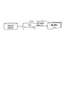
- FIG. 2A is a diagram showing an example of a conceptual configuration of a transit management system according to this embodiment.
- FIG. 2B is a block diagram showing a configuration example of the passage management system according to this embodiment.
- a passage management system 1 according to the present embodiment is a system that manages the passage of people through gates 10 (for example, entrance gates, ticket gates, etc.) installed at entrances and exits of facilities such as airports, stations, and event venues. .
- gates 10 for example, entrance gates, ticket gates, etc.
- entrance/exit management of facility users is executed by face authentication.
- face authentication is used to determine whether the user is authorized to enter the facility.
- users exit the facility through a gate which user exits the facility is determined by face recognition.
- face authentication may be regarded as a concept included in "matching using a face image”.
- the passage management system 1 includes, for example, the gate 10 illustrated in FIG. , a face authentication server 16, and a passage history management server 17.
- the number of gates 10 may be one or plural.
- Gates 10 are installed in facilities such as airports, train stations, and event venues. A user who is permitted to use the facility passes through the gate 10 when entering and/or exiting the facility. Also, the gate 10 is controlled so as to block the passage of persons who are not permitted to enter the facility.
- the camera 11 is provided, for example, on the side wall V of the gate 10, as shown in FIG.
- the camera 11 photographs a photographing range including a person passing through the gate 10 and the face of the person when the person is about to pass through the gate 10 .
- the photographing range of the camera 11 is a range in which the front face of a person can be photographed.
- the image captured by the camera 11 may be used for person detection processing (or person tracking processing), which will be described later, or may be used for face authentication processing, which will be described later.
- the face authentication function unit 13 performs face authentication processing on the image.
- the face authentication function section 13 has a camera control section 131 and a face matching processing section 132 .
- the camera control unit 131 controls the shooting timing of the camera 11, for example.
- the camera 11 shoots at a speed of about 5 fps (frame per second) under the control of the camera control section 131 .
- the right camera 11 and the left camera 11 may shoot simultaneously or with a difference in shooting timing within an allowable range under the control of the camera control unit 131, for example.
- the imaging timing of the right camera 11 and the imaging timing of the left camera 11 are synchronized by control of the camera control section 131, for example.
- the camera control unit 131 detects the face frame from the images (right image and/or left image) captured by the camera 11.
- the method of detecting the face frame is not particularly limited. A method of detecting a frame (face frame) surrounding a face region by detecting a boundary between the region and a region outside the face may be employed.
- the camera control unit 131 outputs information on the detected face frame (face frame information) and the captured image to the face matching processing unit 132 .
- the face matching processing unit 132 cuts out a face area included in the image based on the face frame information, and notifies the face authentication server 16 of a face matching request including information on the cut out face area.
- the face area information may be, for example, an image of the face area or information indicating feature points extracted from the image of the face area.
- a face image registered in the face authentication server 16 may be described as a registered face image.
- a registered face image may be associated with information that can uniquely identify or specify a person, such as an ID (Identification) of a registered person.
- the registered face image may be, for example, information indicating feature points extracted from the image.
- the face authentication server 16 determines whether the face of the same person as the face in the face area included in the face matching request is included in the registered face image. judge. The face authentication server 16 notifies the face matching processing unit 132 of the face matching result including the determination result, for example.
- the face matching result includes, for example, information indicating whether or not the face of the same person as the face in the face area is included in the registered face image (for example, a flag indicating "OK" or "NG");
- information for example, ID of the person associated with the registered face image may be included.
- Verification is, for example, comparing the registered face image with the face image of the person passing through the gate 10 to determine whether the registered face image registered in advance matches the face image of the person passing through the gate 10. Alternatively, it is determined whether or not the face image registered in advance and the face image of the person passing through the gate 10 are of the same person.
- authentication means for example, verifying that a person whose face image matches a pre-registered face image is the person himself/herself (in other words, that the person is permitted to pass through the gate 10). , gate 10).
- the matching process is a process of comparing feature points of registered face images that have been registered in advance with feature points extracted from the detected face area to identify the face in the image data.
- a technique using machine learning may be used.
- the matching process may be performed in the face authentication server 16, for example, but may also be performed in another device such as the gate 10, or may be distributed by a plurality of devices. .
- the face matching processing unit 132 outputs, for example, information including the matching processing result to the passage management function unit 15.
- the result of the matching process may include, for example, information about the registered face image and a matching score indicating the degree of matching of the face images obtained by the matching process.
- the information output from the face matching processing unit 132 may include, for example, face frame detection information, and the photographing time of the face photographing camera image that detected the face frame.
- the person position estimation unit 14 performs person tracking processing, for example, based on face frame information.
- the person position estimation unit 14 includes, for example, a person tracking processing unit 141 .
- the person tracking processing unit 141 estimates the position of the person with respect to the gate 10, for example, based on the face frame information. Then, the person tracking processing unit 141 determines an event that occurs to the person by tracking the estimated position of the person. For example, an event that occurs to a person includes the appearance of a new person, the tracking of a person, and the disappearance of a person. For example, the person tracking processing unit 141 determines an event based on the person's position, and tracks the person by associating the determined event with information such as the person's position and the detection time.
- the person tracking processing unit 141 outputs information on person tracking to the transit management function unit 15, for example.
- information related to person tracking includes information on the location of a person and information such as the time of detection.
- the passage management function unit 15 manages the state of the person positioned around the gate 10 by, for example, associating the information output from the face authentication function unit 13 with the information output from the person position estimation unit 14. .
- a person positioned around the gate 10 includes, for example, a person passing through the gate 10 , a person trying to pass through the gate 10 , and a person passing by the gate 10 .
- the person trying to pass through the gate 10 is not limited to a person who is permitted to pass through the gate 10 (for example, a person whose face image has been registered in the face authentication server 16). It may be a person who is not registered with the authentication server 16 but who tries to pass.
- a person passing through the gate 10 is, for example, a person who is not going to pass through the gate 10 but is passing through the photographing range of the camera 11, or who is not going to pass through the gate 10 but is within the photographing range. It is a person who is entering into Also, the state of a person may be, for example, a state related to the movement of the person, such as whether the person is moving or stationary, and the direction of movement when the person is moving.
- the passage management function unit 15 has, for example, a passage management state transition processing unit 151, a history management unit 152, and a history database (DB) 153.
- the passage management state transition processing unit 151 transmits to the gate 10, for example, control information regarding control of the gate 10 when a person permitted to pass through the gate 10 passes through in the person passage management processing. Also, the passage management state transition processing unit 151 transmits to the gate 10 control information regarding control of the gate 10 when, for example, a person who is not permitted to pass through the gate 10 tries to pass through.
- the history management unit 152 stores and manages, for example, information indicating the history of a person who has passed through the gate 10 (passage history information).
- the history management unit 152 also stores the passage history information in the history DB 153 and transmits the passage history information to the passage history management server 17, for example.
- the history management unit 152 may manage local passage history information for each station (or one ticket gate).
- the passage history management server 17 stores and manages, for example, information (passage history information) indicating the history of a person who has passed through the gate 10 .
- the passage history management server 17 may manage passage history information of multiple gates 10 .
- the passage history information of the gates 10 provided at each of the multiple entrances may be collected and managed by the passage history management server 17 .
- the passage history information of each of the gates 10 installed at the ticket gates of a plurality of stations may be collected and managed by the passage history management server 17 .
- the passage management function unit 15 may output, for example, information (passage management information) related to passage management to a display device (not shown).
- the passage management information may include information output from the face authentication function unit 13 and information output from the person position estimation unit 14, for example.
- the display device may display, for example, the state of a person (for example, the person's face recognition result and movement direction). For example, the display device may display a right image and/or a left image and superimpose the detected face frame on the right image and/or the left image.
- the display device may display information about the person (for example, the person's ID) obtained by face authentication, superimposed on the right image and/or the left image.
- the face authentication function unit 13 described above may operate, for example, in synchronization with or asynchronously with the passage management function unit 15. In the asynchronous case, for example, the face authentication function unit 13 may operate when the camera control unit 131 detects a face frame.
- the above-described three configurations of the face authentication function unit 13, the person position estimation unit 14, and the passage management function unit 15 may each have the form of one information processing device (for example, a server device), Two or more of the three may be included in one information processing device.
- the face authentication function unit 13 may have the form of one information processing device, and the person position estimation unit 14 and the passage management function unit 15 may be included in one information processing device.
- At least one of the face authentication function unit 13 , the person position estimation unit 14 , and the passage control function unit 15 having the form of an information processing device may be included in the gate 10 .
- the information processing apparatus described above may include a processor, a memory, and an input/output interface used to transmit various types of information.
- a processor is a computing device such as a CPU (Central Processing Unit) or a GPU (Graphics Processing Unit).
- the memory is a storage device implemented using RAM (Random Access Memory), ROM (Read Only Memory), or the like.
- the processor, memory, and input/output interface are connected to a bus and exchange various information via the bus.
- the processor for example, reads programs and data stored in the ROM onto the RAM and executes processing, thereby realizing the functions of the configuration included in the information processing apparatus.
- the above-described person position estimation unit 14 and passage management function unit 15 may, for example, define areas (or zones) in the gate 10, and perform person detection and passage management based on the defined zones.
- areas or zones
- An example of the zones defined in gate 10 is described below.
- 3A and 3B are diagrams showing examples of zones defined for the gate 10.
- FIG. FIGS. 3A and 3B show examples of multiple zones when the gate 10 is viewed from above.
- 3A and 3B show an example in which the side wall V of the gate 10 forming the passage L extends along the vertical direction of the paper surface.
- the upstream side along a specific approach direction corresponds to the entrance
- the downstream side corresponds to the exit.
- FIG. 3A shows an example of a zone defined when a person enters from the entrance E2 at a gate 10 that allows a person to enter from both the entrances E1 and E2.
- FIG. 3B shows an example of a zone defined when a person enters through the entrance E1.
- the passage management function defines, for example, the entrance E1 as the "north side" and the entrance E2 as the "south side.”
- references to north and south do not limit the placement of the gates 10 along a geographic north-south direction.
- references to north and south do not limit the placement of the gates 10 along a geographic north-south direction.
- the passage L of the gate 10 is located along a direction different from the north-south direction, or even if the passage includes a curved line, one may be defined as the "north side” and the other as the “south side.” .
- FIG. 3A shows an example of a zone defined when a person enters from the entrance E2.
- "Zone outside-S" (south zone outside area), "Zone A” (zone A), “Zone B” (zone B), and "Zone C” (zone C) Defined.
- FIG. 3B shows an example of a zone defined when a person enters from the entrance E1.
- "Zone outside-N" noden zone outside area
- "Zone A” zone A
- "Zone B” zone B
- "Zone C” zone C
- the boundary between the south outside zone area and zone A may be called, for example, the "face authentication start line".
- Face authentication start line is used, for example, to determine whether to start face authentication processing. For example, when a person crosses the "face authentication start line” and enters the gate 10, the face authentication process is started. For example, a face matching request is issued from face frame information, a matching result (face authentication ID) and person detection information are linked, and tracking of a person is started. Note that the "face authentication start line” may be referred to as "A line”.
- the "face authentication start line” may be provided outside the gate 10 (for example, upstream along the route of the gate 10). Also, the “face authentication start line” is not limited to one line segment, and may have a plurality of line segments such as a U-shape, for example. Note that the shape having a plurality of line segments is not limited to a shape corresponding to a part of the sides of a rectangle such as a U-shape, and may be a shape corresponding to a part of the sides of another polygonal shape. may Alternatively, the "face authentication start line” may have an arc or a shape in which straight lines and curved lines are mixed.
- face authentication start line has a plurality of line segments and/or arcs
- face authentication processing can be started.
- zone A The boundary between zone A and zone B may be called, for example, the "door closing limit line".
- the "door closing limit line” indicates, for example, the position where the exit side gate door can be closed in time in response to the door closing instruction by the time the person passes the exit side gate door position.
- the “door closing limit line” is, for example, the maximum speed assumed as the speed at which a person passes through the gate 10 (for example, 6 km / h, hereinafter referred to as “maximum passable speed”), and the speed until the gate door is physically closed. is determined in consideration of the time (for example, 0.5 seconds) required for For example, the "door closing limit line” is the distance equivalent to "maximum passage speed" x "time required to physically close the gate” from the physical position of the gate ("gate door position"). , is set to the front.
- closed door limit line may also be referred to as "unauthorized intrusion detection line” or "B line”.
- Zone B The boundary between Zone B and Zone C may be referred to as the "exit line".
- the “exit line” indicates, for example, the position where it is determined that the person has exited the gate 10.
- the "exit line” may be provided outside the gate 10, for example, like the "face authentication start line” described above.
- the "exit line” is not limited to one line segment, and may have a plurality of line segments such as a U-shape. Alternatively, the “exit line” may have an arc. Note that the "exit line” may also be called, for example, the "Z line”.
- the gate door position may be just a passing point, and in this case, the gate door position may be different from or the same as the logically set "exit line".
- the "gate door position" and the "exit line” may be set to be the same.
- the "exit line” may correspond to the "charging line”.
- a person who enters the gate 10 crosses the charging line (for example, when entering from zone B to zone C), the person is charged. In other words, when the person has not crossed the charging line (for example, when the person has not entered zone C), the person is not charged.
- the charging line it is possible to avoid the error of charging a person who has entered the gate 10 but turned back before crossing the charging line.
- the "charging line” corresponds to the "Z line" ("exit line"), but for example, the “charging line” may correspond to the "B line”.
- the position of a person By detecting the position of a person with respect to the zones described above, for example, movement between zones is estimated.
- the position of a person is estimated using images captured by the right camera 11 and the left camera 11, for example.
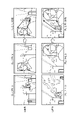
- FIG. 4 is a diagram showing an example of face frame detection according to the present embodiment.
- FIG. 4 shows right images R 1 and R 2 captured by the right camera 11 and left images L 1 and L 2 captured by the left camera 11 .
- the right image R1 and the left image L1 are images captured at the same time t1 , for example.
- the right image R2 and the left image L2 are images captured at the same time t2, for example.
- Time t2 is a time later than time t1.
- the person's position at time t2 is closer to the charge line at gate 10 than the person's position at time t1.
- the right image R 1 , right image R 2 , left image L 1 , and left image L 2 include, for example, a person passing through the gate 10 and a frame (face frame) surrounding the person's face.
- the face frame of the left image L2 is closer to the left end of the image area than the face frame of the left image L1.
- the face frame of the right image R2 is closer to the right end of the image area than the face frame of the right image R1 .
- the horizontal direction in the image area is defined as the horizontal direction or the X-axis direction.
- FIG. 5A is a diagram showing an example of detecting the position of a person according to this embodiment.
- FIG. 5A shows two images based on the image shown in FIG. 4 and extracted images obtained by extracting face frames from the two images.
- Image T1 in FIG. 5A shows an example of comparison of the positional relationship of the face frame between left image L1 and right image R1 at time t1 shown in FIG.
- the right side of image T1 shows the partial area including the face frame of left image L1 shown in FIG. 4
- the left side of image T1 shows the part containing the face frame of right image R1 shown in FIG. indicate the area.
- the face frame of the left image L1 exists to the right of the face frame of the right image R1 .
- Image T2 in FIG . 5A shows an example of comparison of the positional relationship of the face frame between left image L2 and right image R2 at time t2 shown in FIG .
- the right side of image T2 shows the partial region including the face frame of right image R2 shown in FIG . 4
- the left side of image T2 shows the portion containing the face frame of left image L2 shown in FIG . indicate the area.
- the face frame of the left image L2 exists to the left of the face frame of the right image R2 .
- the position of the person is estimated based on the difference between the position of the face frame in the right image and the position of the face frame in the left image.
- the position of the face frame is represented by a representative point of the face frame.
- An example in which the representative point is the center point of the face frame will be described below. Since the center point of the face frame does not change significantly even if the size of the face is different, by using the center point of the face frame as a representative point, even if the size of the person's face varies, position can be stably estimated. However, the present disclosure is not limited to this. If the face frame is rectangular, the representative points may be points indicating the corners of the rectangle. If the face frame is elliptical, the representative point may be the focal point of the ellipse.
- the distance between the point P R indicating the center of the face frame of the right image and the point P L indicating the center of the face frame of the left image is, for example, the point P R may be represented by the horizontal component (along the X-axis) of a vector from point P R to point P L starting at .
- the distance between the face frame point P R of the right image and the face frame point P L of the left image may be referred to as a horizontal coordinate position difference or a position difference.
- point P R is to the left of point P L , so the horizontal component of the vector has a positive value. Also, in the extracted image U2 , since the point P R is to the right of the point P L , the horizontal component of the vector has a negative value.
- FIG. 5B is a diagram showing an example of the relationship between the size of the face frame and the center with respect to the position of the person.
- FIG. 5B shows the positional relationship of the center of the face frame, the size of the face frame, and the vector defined by the center of the face frame for three different distances from the charging line of the gate 10 (far, middle, near). is shown in relation to the direction of
- the center of the face frame of the right image is It exists on the left side, and the center of the face frame of the left image exists on the right side.
- the center of the face frame of the right image moves rightward, and the center of the face frame of the left image moves leftward. Therefore, the direction of the vector from the center of the face frame of the right image to the center of the face frame of the left image changes from the positive direction to the negative direction.
- the polarity of the distance in the horizontal direction to the center of the face frame of the left image is reversed.
- a person's position is estimated by comparing the position difference with a threshold. For example, if the positional difference is equal to or less than the threshold, it is determined that the person is at a position beyond the charging line.
- the position difference when a person passes through a gate, the position difference gradually decreases from a positive value to a negative value.
- the positional difference changes from a positive value to a negative value polarity is determined
- the positional relationship between the face frame of the left image and the face frame of the right image is reversed.
- the face frame of the left image and the face frame of the right image cross each other with the positional difference of zero as the boundary. Therefore, when the positional difference becomes zero, it may be determined that the person exists at a position beyond the charging line.
- the angle of view of the camera, the size of the gate, and the position of the charge line are determined so that the position of the point (cross point) where the face frame of the left image and the face frame of the right image intersect coincides with the charge line.
- the position of the point (cross point) where the face frame of the left image and the face frame of the right image cross is not easily affected by the size of the face frame (that is, the size of the person's face). If the billing line corresponds, the judgment accuracy of the billing line can be improved.
- the center of the face frame is used and the difference between the horizontal coordinates of the center is calculated for estimation, the influence of the difference in the size of the face frame due to the size of the face and/or the height can be avoided, and the estimation accuracy can be improved. can be suppressed or avoided.
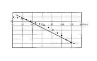
- FIG. 6A is a diagram showing a first example of changes in the magnitude of the position difference.
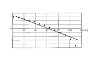
- FIG. 6B is a diagram illustrating a second example of transition of the magnitude of the positional difference.
- 6A and 6B differ from each other in the arrangement of the right camera 11 and the left camera 11.
- FIG. The horizontal axes in FIGS. 6A and 6B indicate the distance along the passage from the position outside the entrance of the gate 10 and where face authentication is possible, and the vertical axis indicates the magnitude of the positional difference. . Note that when the positional difference is a positive value, the center of the face frame of the left image exists to the right of the face frame of the right image. Further, when the positional difference is a negative value, the face frame of the right image exists to the right of the face frame of the left image.
- the position difference takes zero at a certain position. Further, when comparing FIGS. 6A and 6B, the position where the positional difference becomes zero may differ depending on the arrangement of the camera 11. FIG.
- the position where the positional difference is zero can be associated with the charging line.
- the position where the positional difference is zero is defined by the arrangement of the cameras, the position of the billing line can be adjusted appropriately.
- FIG. 7 is a diagram showing an example of the flow of person tracking processing based on the face frame according to the present embodiment.
- the face frame position determination library 201 is, for example, a library that has a function of acquiring face frame detection information and detecting the position of a person corresponding to the face frame.
- the face frame position determination library 201 detects the position of the person from the position of the face frame in the image, for example, by the method described above.
- the face frame position determination library 201 may be given a new person ID.
- the face frame position determination library 201 Continue tracking the person based on the face frame detection information.
- the face frame position determination library 201 outputs person tracking information to the passage management library 202, for example.
- Person tracking information may include, for example, a person ID that identifies a person.
- the person tracking information may also include, for example, information about the location of a person (eg, occurrence of a person, tracking of a person, disappearance of a person, etc.).
- the person tracking information may be compatible between the face frame position determination library 201 and the passage management library 202, for example.
- the passage management library 202 has a function of identifying passage management events at the gate 10 based on, for example, person tracking information.
- the passage management library 202 also outputs, for example, passage management events to the passage management processing unit 203 .
- a passage management event is, for example, an event indicating that a person has moved between zones in a plurality of zones shown in FIGS. 3A and 3B, or an event indicating that a person has crossed a line defining between zones. , an event indicating that a person has appeared in a certain zone, and an event indicating that a person has disappeared in a certain zone.
- the passage management processing unit 203 outputs passage information indicating whether or not a person has passed through the gate 10, or whether or not a person has passed through a charging line, for example, based on a passage management event.
- the result output unit 204 outputs, for example, the result of tracking the person indicated by the passage information. For example, the result output unit 204 displays the results on the display.
- FIG. 8 is a diagram showing an example of areas defined in the image area.
- FIG. 8 shows an image area where the upper left is the origin (0, 0), the horizontal (X-axis) length of the frame is "XframeMax", and the vertical length is "YframeMax”. .
- FIG. 8 also shows, by way of example, a face frame whose one side length is wf and whose upper left coordinates are (Xf, Yf), and the center of the face frame (Xc, Yc).
- the information indicating the face frame may be represented by, for example, X, Y coordinates representing the upper left point of the face frame and wf representing one side of the face frame, as shown in FIG.
- three areas may be defined in the image area of the left image.
- the right area represents the initial appearance area (First Face Frame Area (hereinafter, FFFA)
- the central area represents the middle area (Middle Face Frame Area (hereinafter, MFFA)).
- the left area represents a Passed Face Frame Area (hereinafter referred to as PFFA).
- FIG. 8 shows three areas in the image area of the left image
- the left and right of the three areas may be reversed in the image area of the right image.
- the left area may represent FFFA and the right area may represent PFFA.
- the sizes and positions of the three areas in FIG. 8 are exemplary, and the present disclosure is not limited thereto. The size and position of the three areas may differ from camera 11 to camera 11 .
- the face frame position determination library 201 may determine which of the three areas of the image region the center of the detected face frame is included based on the face frame detection information.
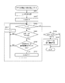
- FIG. 9 is a flow chart showing an example of the flow of passage management.
- the flow shown in FIG. 9 may be started, for example, each time information about an image captured by the camera 11 is obtained.
- the face authentication function unit 13 acquires information on the image captured by the camera 11 and performs processing for detecting a face frame from the image (S101).
- the image information acquired from the camera 11 includes information for identifying the camera that took the image (hereinafter referred to as camera ID), information for identifying the captured frame (hereinafter referred to as frame ID), date and time of image capture, and the like. may be included.
- the face authentication function unit 13 generates information on the detected face frame, and outputs the information on the face frame and the information on the image to the person position estimation unit 14 .
- the information on the face frame may include information indicating the position and size of the face frame. Note that if the face frame is not detected from the image, the processes from S102 onward need not be executed.
- the human position estimation unit 14 performs subsequent processing based on the face frame position determination library 201.
- the person position estimation unit 14 performs face frame timeout processing (S102).
- face frame timeout processing the face frame detection information held in the face frame information list is timed out based on the elapsed time from the timing when the face frame detection information is first acquired. Note that the face frame timeout processing will be described later.
- the person position estimation unit 14 performs face frame detection information generation processing (S103).
- face frame detection information including information on the camera ID, frame ID, shooting date and time, and coordinates of the detected face frame is generated.
- the face frame detection information may include information about the area where the face frame is detected.
- the area where the face frame is detected is determined, for example, based on the definition of the area as illustrated in FIG.
- the definition of the area may be included in the face frame appearance area definition information. Note that when a plurality of face frames are detected in one image, the face frame detection information generation process is executed for each of the plurality of face frames. Note that the face frame detection information generation process will be described later.
- the human position estimation unit 14 performs FFFA multiple face frame elimination processing (S104).
- FFFA multiple face frame elimination processing it is determined whether or not a plurality of face frames exist in FFFA, and if a plurality of face frames exist in FFFA, subsequent processing is not executed. The FFFA multiple face frame elimination process will be described later.
- the person position estimation unit 14 performs time-series face frame detection evaluation processing (S105).
- the face frame detection information is evaluated by comparing the latest information of the face frame detection table and the immediately previous information. For example, when the face frame indicated by the face frame detection information is the face frame of a newly appearing person, a new ID is assigned to the person.
- the human position estimation unit 14 performs a binocular face frame position estimation process (S106). Person tracking information is generated by the binocular face frame position estimation processing. Note that the two-lens method face frame position estimation processing will be described later.
- the person position estimation unit 14 outputs the person tracking data to the passage management function unit 15 (S107). Then, the flow of FIG. 9 ends, and the passage management function unit 15 performs passage management processing based on the passage management library.
- the detection position of the face frame is determined. For example, in each of the right image and the left image, it is determined which area defined in the image region includes the position of the detected face frame.
- the center of the extracted face frame is calculated, and it is determined in which area of FFFA, MFFA, and PFFA the center exists.
- the center of the face frame does not exist in any area, the information on the face frame is discarded.
- the center of the face frame does not exist in any area is because there is a high possibility that it is the face frame of an unauthorized person.
- the minimum face frame size set in the existing area is compared with the size of the face frame. Then, when the size of the face frame is smaller than the minimum face frame size, the information of the face frame is discarded.
- the size of the face frame is smaller than the minimum face frame size, it means that the face of a person who is unlikely to enter the gate 10, or the face drawn on the clothes or the poster is detected, or the pattern that is not the face is detected. This is because there is a high possibility of the face frame of an unauthorized person, such as erroneously detecting a face.
- the determination of the area in which the face frame exists and the comparison with the minimum face frame size set for the area in which the face frame exists are performed by determining the size of the face frame. executed for each.
- a list for time-series determination processing may be generated from the face frame detection information.
- the generated list may be called a face frame information list (or Queue structure list).
- the face frame information list may include information on the center coordinates of the face frame and the appearance area in the image area.
- FIG. 10 is a diagram illustrating an example of face frame timeout processing.
- the face frame to be determined is determined from the time when the face frame to be determined is first detected, for example, the time when the face frame to be determined first appears and a new ID is assigned. is compared with the time limit for holding the face frame (face frame holding time limit).
- face frame holding time limit is a predetermined threshold value and is held in a storage unit or the like.
- the face frame information is deleted from the face frame information list.
- FIG. 9 shows an example in which face frame timeout processing is executed before face frame detection information generation processing, but the present disclosure is not limited to this.
- the face frame timeout process it may be constantly checked whether or not timeout has occurred in the face frame information.
- FIG. 11 is a flowchart showing an example of FFFA multiple face frame exclusion processing. For example, the flow shown in FIG. 11 is started after S103 shown in FIG.
- the human position estimation unit 14 sets the variable i to the number of detected face frames in initial settings (S201). Note that i in FIG. 11 is an integer of 1 or more. In the following description, the number of detected face frames is N (N is an integer equal to or greater than 1). In this case, the N detected face frames are expressed as face frame [1] to face frame [N].
- the human position estimation unit 14 sets the variable "count” to 0 (S202).
- the human position estimation unit 14 determines whether i is greater than 0 (S203).
- the human position estimation unit 14 determines whether or not the face frame [i] is detected within FFFA (S204).
- the human position estimation unit 14 determines whether the size of the face frame [i] is equal to or larger than a predetermined size (S205).
- the predetermined size may be, for example, the size of a face frame with which face authentication can be started, or a size defined based on the size of the face frame with which face authentication can be started.
- the person position estimation unit 14 adds 1 to count (S206).
- the human position estimation unit 14 subtracts 1 from i (S207). Then, the process of S203 is executed.
- the human position estimation unit 14 subtracts 1 from i (S207). Then, the process of S203 is executed.
- the human position estimation unit 14 determines whether count is 2 or more. Determine (S208).
- the human position estimation unit 14 detects the face corresponding to the face frame in the FFFA.
- the frame information is deleted (S209). Then, the flow shown in FIG. 11 ends.
- the human position estimation unit 14 does not delete the face frame information. , the process may end.
- face authentication processing is not executed for each of the detected face frames. If face authentication processing is not executed for each of the detected face frames, the face frame information corresponding to the face frames detected by FFFA may be deleted. Also, in this case, since face authentication processing cannot be executed, error processing is executed. For example, the output control process of the gate device may be instructed via an audio output device and/or a display device to present a warning message to a person attempting to pass through the gate device.
- FIG. 12 is a flow chart showing an example of a two-lens method face frame position estimation process. For example, the flow shown in FIG. 12 is started after S105 shown in FIG.
- the person position estimation unit 14 determines whether or not a face frame exists in the face frame information list (S301).
- the person position estimation unit 14 determines the shooting time when the left image was shot by the left camera 11 and the right image was shot by the right camera 11. It is determined whether or not the difference from the captured time is within the allowable range (S302). In other words, in S302, it is determined whether the shooting times of the left image and the shooting time of the right image are at the same time, almost at the same time, or have an unacceptable difference. In other words, it is determined whether or not the shooting time of the left image and the shooting time of the right image are synchronized.
- the human position estimation unit 14 records a synchronization error in the log (S306).
- the human position estimation unit 14 calculates the difference between the X coordinate of the center of the face frame of the left image and the X coordinate of the center of the face frame of the right image. is calculated (S303).
- the difference between the X coordinates of the center of the face frame may hereinafter be referred to as a "central coordinate difference value”.
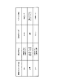
- the human position estimation unit 14 converts the calculated difference into distance information (S304).
- a conversion table may be used for this conversion. An example of the conversion table will be described later.
- the human position estimation unit 14 stores the converted result (S305). Then the flow ends.
- the human position estimation unit 14 When there is no detected face frame (NO in S301), or after recording a synchronization error (after S306), the human position estimation unit 14 outputs a result indicating that position estimation has not been performed. Store (S307). For example, information indicating "no double-lens determination" may be set in the result storage area. Then the flow ends.
- the central coordinate difference value and the estimated position where the target person exists are associated and recorded.
- the numerical information stored in the conversion table may be recorded in units of pixels (for example, in units of 1 pixel).
- the difference value may have a negative number.
- the estimated position where the target person exists may be represented by the distance from the reference point provided on the gate 10, or by the two-dimensional coordinates (eg, X coordinate and Y coordinate) from the reference point. may be represented.
- the conversion table may be developed on-memory, for example, to speed up processing related to passage management.
- a conversion table may be provided for each direction, for example.
- the conversion table may be created when the gate 10 is installed, or may be provided externally.
- the center of the face frame showing the area of the face in the right image obtained by photographing the person's face from the right front of the person entering through the entrance of the gate 10, and the left image obtained by photographing the person's face from the left front.
- the center of the face frame in the image is determined, and the position of the person in the gate 10 is estimated based on the change in the positional relationship between the center of the face frame in the right image and the center of the face frame in the left image.
- passage management processing including authentication processing and tracking processing is performed by performing tracking processing using an image captured by a camera used for face authentication processing.
- the camera used for authentication processing can be used for tracking processing without providing a device for tracking processing (for example, a camera on the ceiling, etc.).
- a passage management system can be introduced without limiting the location.
- the position of a person in order to estimate the position of a person based on the distance between the center of the face frame obtained from each of the left image and the right image, between the right camera 11 and the left camera 11, Even if there are differences in installation position, angle of view, image quality, and resolution, estimation can be performed.
- a stereo camera uses the parallax of both cameras to measure the distance to the subject. Therefore, in the stereo camera, it is necessary to strictly adjust the angles of both cameras, and control processing dedicated to the stereo camera is required.
- the position is estimated using the positional relationship of the face frame detected in the face authentication process, so the position can be estimated more easily than the stereo camera method without strictly adjusting the camera. .
- FIG. 1 shows an example in which the distance from the entrance E1 of the gate 10 to the right camera 11 (camera 11-R1) and the distance from the entrance E1 to the left camera 11 (camera 11-L1) are equal, but the present disclosure is not limited to this.
- one of the right camera 11 and the left camera 11 may be installed at a position closer to the entrance E1 of the gate 10 than the other. That is, in this case, since there is a difference between the installation positions of the right camera 11 and the left camera 11 with respect to the entrance E1 of the gate 10, there is a front-rear difference between the photographing range of the right image and the photographing range of the left image. .
- the left camera 11 when the left camera 11 is provided at a position closer to the entrance E1 than the right camera 11, when the face frames of the left image and the right image are compared, the face frame in the left image is larger than the face frame in the right image. There is a high possibility that the face frame will be outside the image area first, and the face frame will not be detected. In such a case, the area defined as the image area should be changed.
- a case where the left camera 11 is provided closer to the entrance E1 than the right camera 11 will be described below as an example.
- FIG. 13 is a diagram showing an example of prescribed areas for differences in camera placement.
- FIG. 13 shows images captured by the right camera 11 and left camera 11 at two points in time, face frames detected in each image, and defined areas in each image.
- Each image in FIG. 13 includes person A entering the gate 10 and person B entering the gate 10 from behind person A.
- the face frame of the person A in the left image is outside the image area before the face frame of the person A in the right image. go off to
- the face frame of person A in the left image is out of the image area, the face frame of person B in the left image and the face frame of person A in the right image are the same person. may be erroneously determined. Therefore, as shown in FIG. 13, the PFFA in the image of the right camera 11 is set narrower in the horizontal direction than the PFFA in the image of the left camera 11 . With this setting, for example, the timing at which the center of the face frame deviates from the PFFA can be aligned between the left image and the right image.
- ⁇ Control example 1 when an image cannot be acquired from one camera> there may be a case where the face frame cannot be detected in an image captured by one of the two cameras.
- the face frame detection process fails in the image captured by one of the cameras, or if a defect occurs in the shooting of one camera (for example, camera failure, temporary malfunction).
- passage management is performed based on the face frame detected in the image captured by the other camera when the face frame cannot be detected in the image captured by one of the two cameras.
- a processing method performed by an image captured by one camera may be referred to as a single-lens method.
- the position of the person is calculated based on the amount of movement of the face frame in the right image. may be estimated.
- this person position estimation processing for example, when a person who newly passes through the gate 10 appears in time series, the face frame of the person is detected. An example of detecting a face frame of a new person will be described below.
- FIG. 14 is a flowchart showing an example of new face frame detection using one camera. The flow shown in FIG. 14 is executed, for example, when information about an image captured by one of the right camera 11 and the left camera 11 is acquired and information about an image is not acquired from the other, or when the right camera 11 and the left camera 11 may be executed if any one of them fails to shoot.
- the face authentication function unit 13 acquires information on the image captured by the camera 11 and performs processing to detect the face frame from the image (S401).
- the person position estimation unit 14 determines whether or not the size of the face frame is equal to or larger than the specified size (S402).
- the person position estimation unit 14 performs same person determination processing (S403). For example, the person position estimating unit 14 determines whether or not the same person as the person with the detected face frame exists among the people with the face frames shown in the past face frame information list. For example, this determination may be performed by comparing respective feature points, similar to the face recognition process.
- the person position estimation unit 14 determines whether or not they are the same person (S404).
- the person position estimation unit 14 determines whether the center position of the detected face frame is included in the new appearance zone (eg, FFFA) (S405).
- the person position estimation unit 14 determines that the detected face frame is the face frame of the newly appearing person, Information on the face frame is registered (S406). Then the flow ends.
- the person corresponding to the detected face frame may be determined that the person corresponding to the detected face frame is different from the persons corresponding to the face frames detected so far, and that the face frame is a new person. If it is within the zone, it is recognized as the face frame of a new person. For example, information may be registered in a face frame tracking management table. In this case, a face matching request may be notified.
- the human position estimation unit 14 detects It is determined that the face frame obtained is an unmanaged face frame (S407). Then the flow ends.
- the person position estimation unit 14 executes the same person tracking process (S408). Then the flow ends.
- the same person determination process is not particularly limited. For example, it may be determined whether or not the person is the same person based on the amount of movement of the face frame. For example, a predetermined range of movement amount set based on the shooting interval (the range in which the person can move with respect to the shooting interval (eg, 60 msec)) is compared with the amount of movement of the face frame between the two images, If the amount of movement of the face frame is within a predetermined range, it may be determined that they are the same person.
- a predetermined range of movement amount set based on the shooting interval the range in which the person can move with respect to the shooting interval (eg, 60 msec)
- the amount of movement of the face frame is within a predetermined range, it may be determined that they are the same person.
- FIG. 15 is a flow chart showing an example of the charge line crossing determination using one camera.
- the flow shown in FIG. 15 is, for example, a case in which information about an image captured by one of the right camera 11 and the left camera 11 is acquired and no image information is acquired from the other, or It may be executed when one of them cannot shoot.
- the human position estimation unit 14 calculates the center position of the face frame (S501).
- the person position estimating unit 14 determines whether or not the center position of the face frame exists within the charging zone (eg, PFFA) (S502).
- the human position estimation unit 14 may end the process.
- the person position estimation unit 14 determines whether the initial appearance of the face frame is in a zone different from the new appearance zone (eg, FFFA). (S503). For example, among the face frame information indicating that the person is the same as the face frame whose center position is in the billing zone, the information of the first detected face frame is referred to, and the zone in which the referenced face frame is detected is a newly appearing zone.
- FFFA new appearance zone
- the determination result indicating that the person is not charged may be recorded.
- the person position estimation unit 14 determines that the size of the face frame is the threshold defined in the billing zone. It is determined whether or not it is equal to or larger than the face frame size (S504).
- the human position estimation unit 14 may end the process.
- human position estimation unit 14 determines whether the size of the face frame is increasing ( S505). For example, the person position estimating unit 14 refers to the face frame information indicating that the person is the same as the face frame to be determined, and determines whether the size of the face frame increases as the shooting time of the image progresses. You can judge whether
- the person position estimating unit 14 may end because the person is not charged. Note that, in this case, a determination result indicating that the charge has not been made may be recorded. Then, if the same determination result continues for the person for a certain period of time, it means that the person has stayed inside the gate 10 for a certain period of time, so a warning may be presented from the gate 10. .
- the person position estimation unit 14 confirms that the person has entered a charging zone (for example, zone C) at the gate 10 (S506). ). The person position estimation unit 14 notifies the determined result to the server (for example, the face authentication server 16 and/or the passage history management server 17 in FIG. 2A), so that the person is charged. Then the flow ends.
- a charging zone for example, zone C
- the server for example, the face authentication server 16 and/or the passage history management server 17 in FIG. 2A
- each zone is provided with a threshold for the size of the face frame, and if the center position of the face frame belongs to each zone and the size of the face frame exceeds the threshold of the zone to which it belongs, It may be determined that the face frame is located in the zone to which it belongs. This determination is performed in order from PFFA, which has the largest face frame size, to MFFA, and then to FFFA. Which zone it belongs to can be determined appropriately.
- the size of the face frame exceeds the threshold associated with PFFA. If so, it is determined that the face frame belongs to PFFA, omitting the determination of whether the size of the face frame exceeds the threshold associated with MFFA. If the size of the face frame is equal to or less than the threshold associated with PFFA, the face frame is determined to belong to MFFA if the size of the face frame exceeds the threshold associated with MFFA. do.
- the center position of the face frame belongs to both MFFA and FFFA
- the size of the face frame is the largest in PFFA and the smallest in FFFA, so the threshold value associated with each zone may be a value corresponding to this size relationship. However, other values may be employed, such as setting the same threshold value associated with all zones.
- the billing line crossing determination (single-lens system) using one camera is performed. I used to go there, but it's not limited to this.
- the one-lens system may be used. In this case, charging is performed when a person passes the charging line in both methods, and charging is not performed when a person does not pass the charging line in either method. can be determined.
- billing is performed when the billing line is passed by either method, billing can be reliably performed even if the determination is erroneous in either method.
- only the single eye system may be used.
- the present disclosure is not limited to this.
- the present disclosure may be applied to a case where there is no side wall of the passageway and a regulation portion (for example, a door) that regulates the passage of a person.
- the present disclosure may be applied as long as it is a moving route from a certain zone to another zone where a person is permitted to enter according to authentication processing.
- a camera that captures the face of a person passing through the movement route may be installed, for example, on a support or the like provided on the movement route.
- the embodiment described above shows an example of charging a person who has passed through the gate 10, the present disclosure is not limited to this.
- the present disclosure may be applied to record and/or manage transit without billing. Also, for example, in a case where entry is recorded when entering a station, and charging is performed based on the entry record when exiting, the present disclosure may be applied both when entering and when exiting. .
- the determination is made using the right image and the left image taken at the same time, but the present invention is not limited to this.
- a right image and a left image taken at synchronized times, but not at the same time may be used.
- determination results similar to those in the above-described embodiment can be obtained. can be done.
- an authentication target is a person
- the present disclosure is not limited to this.
- it may be applied to moving objects such as animals and vehicles.
- an example of performing face authentication has been described in the present embodiment, the present disclosure is not limited to this.
- the present disclosure may be applied to authentication using an ID card indicating that the person has the right to pass through the gate, and other authentication methods such as biometric authentication.
- face authentication and other authentication methods may be used together. Even if passage is not permitted in face authentication according to the disclosure of the above-described embodiment, passage may be exceptionally permitted if ID card information is input.
- the camera 11 is used for both authentication processing and tracking processing, but the present disclosure is not limited to this.
- an image captured by the camera 11 may be used for person tracking processing (position estimation processing) and not used for face authentication processing.
- position estimation processing position estimation processing
- face authentication processing authentication using an ID card indicating that the person has the right to pass through the gate or other authentication such as biometric authentication is used instead of the face authentication process
- the image captured by the camera 11 is used for the person tracking process. It may be a configuration that is used for (position estimation processing) and not used for face authentication processing.
- the camera 11 is not limited to being provided on the side wall V.
- camera 11 may be attached to a support provided on gate 10 .
- the support may be, for example, a pole extending vertically from the gate 10 or an arch-shaped member provided to cover the side wall of the gate 10 .
- the gate 10 is not limited to an example in which two side walls V form a passage.
- sidewall V may be absent. If there is no side wall V, the camera 11 may be placed at a desired position by a member such as a pole. Even in a configuration without the side wall V, the person is tracked based on the positional relationship of the face frame detected from the image captured by the camera 11, as in the above-described embodiment.
- person tracking using a camera that captures images from another angle may be used together with the configuration shown in the above-described embodiment.
- person tracking using a ceiling camera may be used together.
- person tracking the accuracy of estimating the person's position and moving direction can be improved.
- a surveillance camera installed in the station premises may be used together as the ceiling camera.
- the success or failure of the face authentication processing by the face authentication function unit 13 and the success or failure of the determination of passage through the exit line by the passage management function unit 15 may be output by voice and/or image.
- different sounds and/or images may be output depending on whether the face authentication process is successful or not, and whether or not the exit line has been passed.
- the person fails to pass through the gate 10 it is possible to distinguish between the step of obtaining permission to pass through the gate 10 (success or failure of face authentication processing) or the step of confirming passage through the gate (success or failure of passing). may be notified separately.
- the door is used as means for restricting passage through the gate 10, but other means may be used to directly or indirectly restrict passage. For example, by sounding an alarm or turning on a warning light, a person attempting to pass through the gate 10 may be notified that passage through the gate 10 is restricted. Also, by sending a notification to a terminal or the like owned by an employee near the gate 10, the employee may restrict passage.
- whether or not to perform control to block passage or the means to restrict passage may be switched. For example, in an environment where it would be dangerous to block or restrict the passage of a person, such as when a large number of people enter and leave, the passage through the gate 10 is not blocked and information indicating that there has been an unauthorized passage is recorded. good too. In this case, the face image of the person who passed through illegally or the result of face authentication may be recorded in association with the information indicating the illegal passage. As a result, it becomes possible to track down a person who has illegally passed through and to claim compensation for the right of way.
- the passage management system 1 manages both entrances to and exits from facilities such as airports, train stations, and event venues. , one of entering or exiting the facility may be controlled, and the other may not be controlled.
- the present disclosure can be realized by software, hardware, or software linked to hardware.
- Each functional block used in the description of the above embodiments is partially or wholly realized as an LSI, which is an integrated circuit, and each process described in the above embodiments is partially or wholly implemented as It may be controlled by one LSI or a combination of LSIs.
- An LSI may be composed of individual chips, or may be composed of one chip so as to include some or all of the functional blocks.
- the LSI may have data inputs and outputs.
- LSIs are also called ICs, system LSIs, super LSIs, and ultra LSIs depending on the degree of integration.
- the method of circuit integration is not limited to LSI, and may be realized with a dedicated circuit, a general-purpose processor, or a dedicated processor. Further, an FPGA (Field Programmable Gate Array) that can be programmed after the LSI is manufactured, or a reconfigurable processor that can reconfigure the connections and settings of the circuit cells inside the LSI may be used.
- FPGA Field Programmable Gate Array
- reconfigurable processor that can reconfigure the connections and settings of the circuit cells inside the LSI may be used.
- the present disclosure may be implemented as digital or analog processing.
- a communication device may include a radio transceiver and processing/control circuitry.
- a wireless transceiver may include a receiver section and a transmitter section, or functions thereof.
- a wireless transceiver (transmitter, receiver) may include an RF (Radio Frequency) module and one or more antennas.
- RF modules may include amplifiers, RF modulators/demodulators, or the like.
- Non-limiting examples of communication devices include telephones (mobile phones, smart phones, etc.), tablets, personal computers (PCs) (laptops, desktops, notebooks, etc.), cameras (digital still/video cameras, etc.).
- digital players digital audio/video players, etc.
- wearable devices wearable cameras, smartwatches, tracking devices, etc.
- game consoles digital book readers
- telehealth and telemedicine (remote health care/medicine prescription) devices vehicles or mobile vehicles with communication capabilities (automobiles, planes, ships, etc.), and combinations of the various devices described above.
- Communication equipment is not limited to portable or movable equipment, but any type of equipment, device or system that is non-portable or fixed, e.g. smart home devices (household appliances, lighting equipment, smart meters or measuring instruments, control panels, etc.), vending machines, and any other "Things" that can exist on the IoT (Internet of Things) network.
- smart home devices household appliances, lighting equipment, smart meters or measuring instruments, control panels, etc.
- vending machines and any other "Things” that can exist on the IoT (Internet of Things) network.
- CPS Chip Physical Systems
- IoT Internet of Things
- an edge server located in physical space and a cloud server located in cyber space are connected via a network, and processing is performed by processors installed in both servers. Distributed processing is possible.
- each processing data generated in the edge server or cloud server is preferably generated on a standardized platform.
- various sensor groups and IoT application software can be used. Efficiency can be achieved when constructing a system that includes.
- Communication includes data communication by cellular system, wireless LAN system, communication satellite system, etc., as well as data communication by a combination of these.
- Communication apparatus also includes devices such as controllers and sensors that are connected or coupled to communication devices that perform the communication functions described in this disclosure. Examples include controllers and sensors that generate control and data signals used by communication devices to perform the communication functions of the communication apparatus.
- Communication equipment also includes infrastructure equipment, such as base stations, access points, and any other equipment, device, or system that communicates with or controls the various equipment, not limited to those listed above. .
- An embodiment of the present disclosure is suitable for face authentication systems.
- passage management system 10 gate 11 camera 13 face authentication function unit 131 camera control unit 132 face matching processing unit 14 person position estimation unit 141 person tracking processing unit 15 passage management function unit 151 passage management state transition processing unit 152 history management unit 153 history database 16 face authentication server 17 passage history management server
Landscapes
- Physics & Mathematics (AREA)
- General Physics & Mathematics (AREA)
- Engineering & Computer Science (AREA)
- Human Computer Interaction (AREA)
- Business, Economics & Management (AREA)
- Finance (AREA)
- Devices For Checking Fares Or Tickets At Control Points (AREA)
- Image Analysis (AREA)
- Closed-Circuit Television Systems (AREA)
Abstract
L'invention concerne un dispositif de traitement d'informations, un système de traitement d'informations et un procédé d'estimation, qui permettent d'améliorer la précision d'estimation de la position d'un objet dont est planifié le passage à travers une zone spécifique. Ce dispositif de traitement d'informations comprend une unité de détection qui détecte une première zone d'image faciale comprise dans une première image obtenue par photographie d'une personne, qui pénètre dans un portique, dans une première direction, et une seconde zone d'image faciale comprise dans une seconde image obtenue par photographie de la personne dans une seconde direction différente de la première direction, et une unité d'estimation qui estime la position de la personne dans le portique sur la base d'un changement de la relation de position relative entre la première zone d'image faciale et la seconde zone d'image faciale.
Applications Claiming Priority (2)
| Application Number | Priority Date | Filing Date | Title |
|---|---|---|---|
| JP2021-069251 | 2021-04-15 | ||
| JP2021069251A JP7122543B1 (ja) | 2021-04-15 | 2021-04-15 | 情報処理装置、情報処理システム、及び、推定方法 |
Publications (1)
| Publication Number | Publication Date |
|---|---|
| WO2022219932A1 true WO2022219932A1 (fr) | 2022-10-20 |
Family
ID=82940124
Family Applications (1)
| Application Number | Title | Priority Date | Filing Date |
|---|---|---|---|
| PCT/JP2022/007304 WO2022219932A1 (fr) | 2021-04-15 | 2022-02-22 | Dispositif de traitement d'informations, système de traitement d'informations et procédé d'estimation |
Country Status (2)
| Country | Link |
|---|---|
| JP (2) | JP7122543B1 (fr) |
| WO (1) | WO2022219932A1 (fr) |
Cited By (1)
| Publication number | Priority date | Publication date | Assignee | Title |
|---|---|---|---|---|
| JP7445906B1 (ja) | 2022-12-02 | 2024-03-08 | パナソニックIpマネジメント株式会社 | 設置支援装置、設置支援方法、及び、設置支援プログラム |
Citations (2)
| Publication number | Priority date | Publication date | Assignee | Title |
|---|---|---|---|---|
| JP2006236244A (ja) * | 2005-02-28 | 2006-09-07 | Toshiba Corp | 顔認証装置および入退場管理装置 |
| JP2019053675A (ja) * | 2017-09-19 | 2019-04-04 | 日本電気株式会社 | 照合システム |
-
2021
- 2021-04-15 JP JP2021069251A patent/JP7122543B1/ja active Active
-
2022
- 2022-02-22 WO PCT/JP2022/007304 patent/WO2022219932A1/fr active Application Filing
- 2022-07-04 JP JP2022107696A patent/JP2022164659A/ja active Pending
Patent Citations (2)
| Publication number | Priority date | Publication date | Assignee | Title |
|---|---|---|---|---|
| JP2006236244A (ja) * | 2005-02-28 | 2006-09-07 | Toshiba Corp | 顔認証装置および入退場管理装置 |
| JP2019053675A (ja) * | 2017-09-19 | 2019-04-04 | 日本電気株式会社 | 照合システム |
Cited By (1)
| Publication number | Priority date | Publication date | Assignee | Title |
|---|---|---|---|---|
| JP7445906B1 (ja) | 2022-12-02 | 2024-03-08 | パナソニックIpマネジメント株式会社 | 設置支援装置、設置支援方法、及び、設置支援プログラム |
Also Published As
| Publication number | Publication date |
|---|---|
| JP7122543B1 (ja) | 2022-08-22 |
| JP2022164659A (ja) | 2022-10-27 |
| JP2022164038A (ja) | 2022-10-27 |
Similar Documents
| Publication | Publication Date | Title |
|---|---|---|
| EP1806702A2 (fr) | Système d'authentification de visage et système de gestion de portes de passage | |
| JP2010154134A (ja) | 映像監視システム | |
| JP7432867B2 (ja) | 照合装置、照合システム、及び、照合方法 | |
| TW201340037A (zh) | 同步無間隙式多管制要件結合分離裝置 | |
| WO2022219932A1 (fr) | Dispositif de traitement d'informations, système de traitement d'informations et procédé d'estimation | |
| JP7108938B2 (ja) | 情報処理装置、情報処理システム、及び、通過管理方法 | |
| JP2008059179A (ja) | ゲート監視システム及びゲート監視方法 | |
| JP2023075227A (ja) | 情報処理装置、及び、情報処理方法 | |
| JP2010262527A (ja) | 通行者計数装置、通行者計数方法および通行者計数プログラム | |
| JP2023153850A (ja) | ゲート装置、認証システム、ゲート装置の制御方法及び記憶媒体 | |
| WO2021176593A1 (fr) | Dispositif de gestion de séjour, procédé de gestion de séjour, support lisible par ordinateur non transitoire dans lequel un programme est stocké, et système de gestion de séjour | |
| KR20170007070A (ko) | 방문객 출입 통계 분석 방법 및 장치 | |
| JP2012133411A (ja) | 顔照合システム、顔照合装置及び顔照合方法 | |
| JP7218837B2 (ja) | ゲート装置、認証システム、ゲート装置の制御方法及びプログラム | |
| JP2013186876A (ja) | 無人化判定装置、無人化判定方法および無人化判定プログラム | |
| JP2021135663A (ja) | 情報処理装置、顔認証システム、及び、情報処理方法 | |
| JP7327650B2 (ja) | ゲート装置、認証システム、ゲート装置の制御方法及びプログラム | |
| WO2019156599A1 (fr) | Système et procédé de contrôle de déplacement des personnes | |
| AU2020435735B2 (en) | Gate system, gate apparatus, image processing method therefor, program, and arrangement method for gate apparatus | |
| WO2023176167A1 (fr) | Dispositif, procédé et programme d'enregistrement | |
| JP2009129131A (ja) | 通過検出システム、および通過検出方法 | |
| JP2024065337A (ja) | 通行管理プログラム、通行管理方法、および通行管理装置 | |
| CN114944030A (zh) | 一种门禁控制方法及装置 | |
| Chen | Cloud-assisted mobile sensing systems |
Legal Events
| Date | Code | Title | Description |
|---|---|---|---|
| 121 | Ep: the epo has been informed by wipo that ep was designated in this application |
Ref document number: 22787860 Country of ref document: EP Kind code of ref document: A1 |
|
| WWE | Wipo information: entry into national phase |
Ref document number: 18286715 Country of ref document: US |
|
| NENP | Non-entry into the national phase |
Ref country code: DE |
|
| 122 | Ep: pct application non-entry in european phase |
Ref document number: 22787860 Country of ref document: EP Kind code of ref document: A1 |