WO2022219682A1 - エレベーターの制御システムおよびエレベーターの制御方法 - Google Patents
エレベーターの制御システムおよびエレベーターの制御方法 Download PDFInfo
- Publication number
- WO2022219682A1 WO2022219682A1 PCT/JP2021/015193 JP2021015193W WO2022219682A1 WO 2022219682 A1 WO2022219682 A1 WO 2022219682A1 JP 2021015193 W JP2021015193 W JP 2021015193W WO 2022219682 A1 WO2022219682 A1 WO 2022219682A1
- Authority
- WO
- WIPO (PCT)
- Prior art keywords
- car
- pattern
- speed
- landing
- running
- Prior art date
- Legal status (The legal status is an assumption and is not a legal conclusion. Google has not performed a legal analysis and makes no representation as to the accuracy of the status listed.)
- Ceased
Links
Images






Classifications
-
- B—PERFORMING OPERATIONS; TRANSPORTING
- B66—HOISTING; LIFTING; HAULING
- B66B—ELEVATORS; ESCALATORS OR MOVING WALKWAYS
- B66B1/00—Control systems of elevators in general
- B66B1/24—Control systems with regulation, i.e. with retroactive action, for influencing travelling speed, acceleration, or deceleration
- B66B1/28—Control systems with regulation, i.e. with retroactive action, for influencing travelling speed, acceleration, or deceleration electrical
- B66B1/30—Control systems with regulation, i.e. with retroactive action, for influencing travelling speed, acceleration, or deceleration electrical effective on driving gear, e.g. acting on power electronics, on inverter or rectifier controlled motor
-
- B—PERFORMING OPERATIONS; TRANSPORTING
- B66—HOISTING; LIFTING; HAULING
- B66B—ELEVATORS; ESCALATORS OR MOVING WALKWAYS
- B66B1/00—Control systems of elevators in general
- B66B1/24—Control systems with regulation, i.e. with retroactive action, for influencing travelling speed, acceleration, or deceleration
- B66B1/28—Control systems with regulation, i.e. with retroactive action, for influencing travelling speed, acceleration, or deceleration electrical
- B66B1/285—Control systems with regulation, i.e. with retroactive action, for influencing travelling speed, acceleration, or deceleration electrical with the use of a speed pattern generator
-
- B—PERFORMING OPERATIONS; TRANSPORTING
- B66—HOISTING; LIFTING; HAULING
- B66B—ELEVATORS; ESCALATORS OR MOVING WALKWAYS
- B66B1/00—Control systems of elevators in general
- B66B1/34—Details, e.g. call counting devices, data transmission from car to control system, devices giving information to the control system
- B66B1/3492—Position or motion detectors or driving means for the detector
-
- B—PERFORMING OPERATIONS; TRANSPORTING
- B66—HOISTING; LIFTING; HAULING
- B66B—ELEVATORS; ESCALATORS OR MOVING WALKWAYS
- B66B1/00—Control systems of elevators in general
- B66B1/34—Details, e.g. call counting devices, data transmission from car to control system, devices giving information to the control system
- B66B1/36—Means for stopping the cars, cages, or skips at predetermined levels
- B66B1/40—Means for stopping the cars, cages, or skips at predetermined levels and for correct levelling at landings
Definitions
- the present disclosure relates to an elevator control system and an elevator control method.
- Patent Document 1 discloses an example of an elevator control device.
- the control device generates an acceleration command during landing control according to the time delay of the control signal.
- the acceleration command generated by the control device of Patent Document 1 changes discontinuously after the delay time tdelay.
- the vibration of the car is induced during landing control, which may deteriorate ride comfort.
- the present disclosure relates to solving such problems.
- the present disclosure provides an elevator control system and an elevator control method capable of suppressing deterioration of ride comfort due to car vibration during landing control.
- the elevator control system includes a position detection unit that detects the current position of the car in the traveling direction, and a starting point that detects passage of the car at a starting position that is a predetermined distance away from the floor landing position of the car. a detection unit and a plurality of driving patterns each generating a running pattern from the starting position to the landing position in which the acceleration is continuous from before the car passes the starting position until the car stops, based on algorithms different from each other.
- a running control unit for causing the running of the car to follow a running pattern generated by one of the plurality of pattern generating units based on the current position of the car detected by the position detecting unit; From among the running patterns generated by each of the plurality of pattern generation units, based on the speed of the car at the timing when the starting point detection unit detects passage of the car, travel from the starting position to the landing position is performed.
- a pattern selection unit that selects a travel pattern requiring the shortest landing time as a travel pattern for which the travel control unit follows the travel of the car.
- An elevator control method includes a starting point detection step of detecting passage of the car at a starting point position a predetermined distance away from a landing position of the car; a speed acquisition step of acquiring the speed of the car at the timing when the passage is detected; Among a plurality of traveling patterns based on mutually different algorithms, the landing time required for traveling from the starting position to the landing position is the shortest based on the speed of the car acquired in the speed acquisition step. a pattern selection step of selecting a travel pattern; and a travel control step of causing the travel of the car to follow the travel pattern selected in the pattern selection step based on the current position of the car.
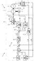
- FIG. 1 is a configuration diagram of an elevator according to Embodiment 1;
- FIG. FIG. 4 is a diagram showing an example of running patterns in the control system according to Embodiment 1;
- FIG. 4 is a block diagram showing the configuration of a landing instruction unit according to Embodiment 1;
- FIG. 3 is a block diagram showing the configuration of a first pattern generation unit according to Embodiment 1;
- FIG. FIG. 5 is a diagram showing an example of a running pattern generated by a constant jerk pattern generator according to Embodiment 1;
- FIG. 4 is a diagram showing an example of a running pattern generated by a correction pattern generation unit according to Embodiment 1;
- FIG. 4 is a diagram showing an example of a running pattern generated by a first pattern generator according to Embodiment 1;
- FIG. FIG. 5 is a diagram showing an example of a running pattern generated by a second pattern generator according to Embodiment 1;
- FIG. 5 is a diagram showing the relationship between the floor landing time and the speed of the car in the running pattern generated by the pattern generator according to the first embodiment;
- 4 is a diagram showing an example of a running pattern generated by a first pattern generator according to Embodiment 1;
- FIG. 4 is a diagram showing an example of a running pattern generated by a first pattern generator according to Embodiment 1;
- FIG. 4 is a diagram showing an example of a running pattern generated by a first pattern generator according to Embodiment 1;
- FIG. 4 is a flow chart showing an example of the operation of the control system according to Embodiment 1; 4 is a flow chart showing an example of the operation of the control system according to Embodiment 1; 4 is a flow chart showing an example of the operation of the control system according to Embodiment 1; 2 is a hardware configuration diagram of main parts of the control system according to Embodiment 1.
- FIG. FIG. 2 is a configuration diagram of an elevator according to Embodiment 2;
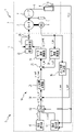
- FIG. 1 is a configuration diagram of an elevator 1 according to Embodiment 1. As shown in FIG. 1
- the elevator 1 is applied, for example, to a building with multiple floors.
- a hoistway 2 for an elevator 1 is provided in a building.
- the hoistway 2 is a vertically elongated space that spans a plurality of floors.
- the elevator 1 comprises a motor 3, a sheave 4, a main rope 5, a car 6 and a counterweight 7.
- the motor 3 is provided, for example, at the top or bottom of the hoistway 2.
- the motor 3 may be arranged in the machine room.
- Sheave 4 is connected to the rotating shaft of motor 3 .
- a main rope 5 is wound around the sheave 4 .
- Main rope 5 supports the load of car 6 on one side of sheave 4 .
- Main rope 5 supports the load of counterweight 7 on the other side of sheave 4 .
- the car 6 is a device that transports users and the like between a plurality of floors by traveling up and down the hoistway 2 .
- the counterweight 7 is a device that balances the load applied to both sides of the sheave 4 through the main rope 5 with the car 6 .
- the car 6 and the counterweight 7 travel in opposite directions on the hoistway 2 in conjunction with the main rope 5 that moves when the motor 3 drives the sheave 4 to rotate.
- the elevator 1 includes a control system 8.
- a control system 8 is a system that controls the operation of the elevator 1 .
- the control system 8 includes an encoder 9 , a position measurement section 10 , a starting point detection section 11 and a control device 12 .
- the encoder 9 is a device that detects the rotation angle of the motor 3. An encoder 9 is attached to the motor 3 . The encoder 9 outputs a signal of the detected rotation angle x_m of the motor 3 to the control device 12 .
- the position measuring unit 10 is a part that detects the current position of the car 6 in the traveling direction by measurement.
- the position measurement unit 10 is an example of a position detection unit.
- the position measuring unit 10 is an APS (Absolute Positioning System) sensor.
- a position measuring unit 10 is provided in the car 6 .
- an APS cord tape 13 is provided along the vertical direction in the hoistway 2 .
- the code tape 13 is a tape showing an image in which information indicating a position in the vertical direction is encoded.
- the position measuring unit 10 detects the current position of the car 6 by reading information on the code tape 13 .
- the position measurement unit 10 outputs a signal of the detected current position x_car of the car 6 to the control device 12 .
- the origin detection unit 11 is a part that detects passage of the car 6 at the origin position.
- the origin detection unit 11 is provided in the car 6 .
- the starting point position is a predetermined position in the running direction of the car 6 .
- a plurality of starting positions are set. In this example, the starting position is set at a point that is a preset distance away from the landing position of each floor.
- a detector 14 is provided in the hoistway 2 at the starting position of each floor.
- the detection body 14 is, for example, a landing plate.
- the control device 12 is a device that performs control processing and the like in the elevator 1.
- the control device 12 is composed of, for example, an electric board.
- the control device 12 may be composed of a plurality of devices. A part or all of the control device 12 is provided, for example, above or below the hoistway 2 . Alternatively, when a machine room of the elevator 1 is provided, part or all of the controller 12 may be arranged in the machine room.
- the control device 12 controls running of the car 6 in a plurality of control modes. Control modes include an inter-floor travel mode and a floor landing mode.
- the inter-floor travel mode is a control mode when the car 6 travels between the departure floor and the destination floor.
- the landing mode is a control mode when the car 6 lands at the landing position of the destination floor.
- the control mode in the control device 12 is switched from the inter-floor traveling mode to the floor landing mode, for example, when the car 6 passes through the origin position corresponding to the floor landing position of the destination floor.
- the control device 12 includes a car speed calculation unit 15 , a travel command unit 16 , a landing command unit 17 , a control mode switching unit 18 and a travel control unit 19 .
- the car speed calculation unit 15 calculates the speed of the car 6 by time differentiation or the like based on the signal of the current position x_car of the car 6 input from the position measurement unit 10 .
- the car speed calculator 15 outputs a signal of the calculated speed v_car of the car 6 .
- the travel command unit 16 is a part that generates the travel pattern of the car 6 traveling between the departure floor and the destination floor, that is, the travel pattern in the inter-floor travel mode.
- the traveling pattern is, for example, a waveform representing values such as the position, speed, acceleration, or jerk of the car 6 at each time.
- the travel pattern is a waveform of car 6 positions.
- the running pattern in the inter-floor running mode includes acceleration running, deceleration running, and the like. Acceleration travel is travel with a constant acceleration such that the absolute value of the speed increases when the car 6 departs from the departure floor. Deceleration running is running with a constant acceleration such that the absolute value of the speed decreases when the car 6 arrives at the destination floor.
- the running pattern may include constant speed running at a constant speed between acceleration running and deceleration running.
- the travel command unit 16 outputs a signal representing the travel pattern x_ref0 in the inter-floor travel mode.
- the landing command unit 17 is a part that generates the running pattern of the car 6 when landing at the landing position on the destination floor, that is, the running pattern in the landing mode.
- the control mode is switched to the landing mode during deceleration travel in the inter-floor travel mode.
- the landing command unit 17 acquires the speed of the car 6 based on the speed v_car signal output by the car speed calculation unit 15 .
- the landing command unit 17 determines the timing of passage of the car 6 at the origin position corresponding to the landing position on the destination floor based on the detection signal LS_t output by the origin detection unit 11 .
- the floor landing command unit 17 generates a floor landing mode travel pattern based on the speed of the car 6 when the car 6 passes through the starting position.
- the landing command unit 17 outputs a signal representing the traveling pattern x_ref in the landing mode.
- the control mode switching unit 18 is a part that switches the control mode in the control device 12 .
- the control mode switching unit 18 selects a driving pattern according to the control mode in the control device 12 from the driving patterns such as the driving pattern x_ref0 from the driving command unit 16 and the driving pattern x_ref from the landing command unit 17. It is output as a signal of the running pattern x_ref1.
- the control mode switching unit 18 sets the control mode to the inter-floor traveling mode when the car 6 departs from the departure floor toward the destination floor. At this time, the control mode switching unit 18 outputs the running pattern x_ref0 from the running command unit 16 as a signal of the running pattern x_ref1 according to the control mode.
- the control mode switching unit 18 determines the timing of passage of the car 6 at the origin position corresponding to the landing position on the destination floor based on the detection signal LS_t output by the origin detection unit 11 .
- the control mode switching unit 18 switches the control mode from the inter-floor traveling mode to the floor landing mode when the car 6 passes through the origin position.
- the control mode switching unit 18 outputs the driving pattern x_ref from the landing instruction unit 17 as a driving pattern x_ref1 signal corresponding to the control mode.
- the running control unit 19 is a part that makes the running of the car 6 follow the running pattern according to the control mode.
- the travel control unit 19 includes a car position control unit 20 , a motor speed calculation unit 21 , a motor speed control unit 22 and a motor current control unit 23 .
- the car position control unit 20 is a part that causes the position of the car 6 to follow the running pattern according to the control mode.
- the car position control unit 20 outputs a control signal x_cont for causing the running of the car 6 to follow the running pattern based on the difference between the position in the running pattern and the position of the car 6 .
- the car position control unit 20 subtracts a signal representing the difference x_err between the running pattern x_ref1 for following the running of the car 6 and the current position x_car of the car 6 detected by the position measuring unit 10 to calculate the difference. received from vessel 24;
- the car position control unit 20 outputs a signal representing the angular velocity target v_ref of the motor 3 as the control signal x_cont.
- the motor speed calculator 21 calculates the angular speed of the motor 3 based on the signal of the rotation angle x_m of the motor 3 input from the encoder 9 .
- the motor speed calculator 21 outputs a signal of the calculated angular speed v_m of the motor 3 .
- the motor speed control unit 22 is a part that causes the angular speed of the motor 3 to follow the angular speed target.
- the motor speed control unit 22 receives a signal representing the difference v_err between the angular speed target v_ref output by the car position control unit 20 and the angular speed v_m of the motor 3 calculated by the motor speed calculation unit 21 from the subtractor 25 that calculates the difference. accept.
- the motor speed control unit 22 Based on the signal of the difference v_err, the motor speed control unit 22 performs control calculations such as proportionality, integration, and differentiation so as to stably obtain the required performance of the motor 3, thereby achieving the target torque current of the motor 3.
- the motor current control unit 23 supplies drive current to the motor 3 in accordance with the input torque current target iq_v_cont signal.
- Motor current control unit 23 receives a signal representing current iq detected by current detector 26 provided in motor 3 from current detector 26 .
- the motor current control unit 23 receives feedback of the signal of the current iq from the current detector 26, and supplies current so that the drive current of the motor 3 matches the torque current target iq_v_cont.
- a velocity control system is realized in which the angular velocity v_m of the motor 3 follows the angular velocity target v_ref so that the velocity difference v_err is within a preset range.
- a position control system is realized in which the position x_car of the car 6 follows the running pattern x_ref1, which is the target position of the car 6, so that the position difference x_err is within a preset range.
- an error may occur depending on the temperature of the usage environment.
- a measuring device for constantly measuring the relative temperature expansion/contraction amount between the APS cord tape 13 and the building may be provided at the lower end of the hoistway 2 or the like.
- such instruments may increase the cost of the elevator 1 control system 8 .
- the control system 8 does not require a measuring instrument or the like to constantly measure the relative temperature expansion/contraction amount between the APS code tape 13 and the building even when there is an error in the current position of the car 6 detected by the position measuring unit 10. Instead, landing control in which the error is corrected is performed.
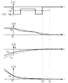
- FIG. 2 is a diagram showing an example of running patterns in the control system 8 according to the first embodiment.
- Examples of driving patterns are shown by four graphs.
- the horizontal axis represents time. The origin of time is taken at the time when the car 6 passes through the origin position corresponding to the landing position of the destination floor.
- the vertical axis represents the position of the car 6 . The origin of the position is set at the landing position of the car 6 on the destination floor.
- the vertical axis represents the speed of the car 6 .
- the vertical axis represents the acceleration of the car 6 . Before time 0, the car 6 is running in the inter-floor running mode at deceleration.
- the magnitude of the acceleration becomes a preset constant value.
- the vertical axis represents the jerk of car 6 .
- the velocity waveform, the acceleration waveform, and the jerk waveform are not output by the control system 8 as the driving pattern signal.
- the position of the car 6 is x 0 [m], which is the position of the detector 14 provided at the origin position corresponding to the landing position on the destination floor.
- the acceleration of the car 6 at this timing is a preset constant value a 0 [m/s 2 ].
- the acceleration of the car 6 maintains continuity before and after passing the starting position.
- the running pattern maintains a constant jerk until the car 6 stops at the landing position. The deceleration of the car 6 with a constant jerk ensures good riding comfort.
- the speed of the car 6 -v 0 [m/s], the landing time T 0 [s], and the constant jerk -J 0 [m/s 3 ] at the timing of passing the starting position are as follows. is represented by equations (1) to (3).
- the landing time is the time required for traveling from the starting position to the landing position.
- Equations (1) to (3) are given by the position x 0 [m] of the detector 14 provided at the origin position and the origin position If the acceleration a 0 [m/ s 2 ] of the car 6 at the timing of passing the This indicates that the bed time T 0 [s] is uniquely determined.
- the speed of the car 6 monotonically decreases during deceleration. Therefore, when there is an error in the current position of the car 6 detected by the position measuring unit 10, the car 6 is traveling at a speed other than the speed ⁇ v 0 [m/s] represented by Equation (1). At the timing, the car 6 will pass the starting position.
- the landing command unit 17 performs landing control by correcting the error of the current position of the car 6 detected by the position measuring unit 10 .
- FIG. 3 is a block diagram showing the configuration of the landing instruction unit 17 according to the first embodiment.
- the landing command unit 17 includes a sample hold 27 , a first pattern generation unit 28 , a second pattern generation unit 29 , a pattern selection unit 30 and a pattern switching unit 31 .
- the sample hold 27 determines the timing of passage of the car 6 at the origin position corresponding to the landing position on the target floor, based on the detection signal LS_t output by the origin detector 11 .
- the sample hold 27 acquires the speed ⁇ v s [m/s] of the car 6 when the car 6 passes the starting position based on the v_car signal output from the car speed calculation unit 15 .
- Each of the first pattern generator 28 and the second pattern generator 29 is an example of a plurality of pattern generators.
- Each pattern generator is a part that generates a running pattern from the starting position to the landing position based on algorithms different from each other.
- Each pattern generator generates a waveform of the position of the car 6 as a running pattern so that the acceleration of the car 6 continues from immediately before passing the starting position until the car 6 stops.
- the first pattern generator 28 outputs the generated positional waveform as a signal of the running pattern x_ref_ar1.
- the second pattern generator 29 outputs the generated positional waveform as a signal of the running pattern x_ref_ar2.
- the pattern selection unit 30 is a part that selects, from among the running patterns generated by the respective pattern generating units, the running pattern x_ref that is output from the landing instruction unit 17 .
- the running pattern output from the floor landing command section 17 is output as a signal of the running pattern x_ref1 in the floor landing mode. Therefore, the travel pattern selected by the pattern selection unit 30 is a travel pattern that the travel control unit 19 causes the car 6 to follow in the landing mode.
- the pattern selection unit 30 selects a running pattern with the shortest landing time from among the running patterns generated by the respective pattern generating units.
- the pattern switching unit 31 is a part that switches the running pattern to be output as the running pattern x_ref based on the selection of the pattern selecting unit 30 from among the running patterns generated by the respective pattern generating units.
- FIG. 4 is a block diagram showing the configuration of the first pattern generator 28 according to Embodiment 1. As shown in FIG.
- the first pattern generator 28 includes a constant jerk pattern generator 32 and a correction pattern generator 33 .
- the constant jerk pattern generator 32 is a part that generates a running pattern with constant jerk.
- a constant jerk pattern generator 32 generates a waveform of the position of the car 6 as a running pattern.
- the constant jerk pattern generator 32 outputs the generated waveform of the position of the car 6 as a signal of the running pattern x_ref_ar11.
- the constant jerk pattern generation unit 32 uses the velocity ⁇ v s [m/s] acquired by the sample hold 27 as the initial velocity, maintains continuity in the acceleration of the car 6 before and after passing the starting position, and maintains a constant acceleration until the car stops. Generate a running pattern that keeps the jerk.
- the velocity ⁇ vs [m/s] at this time may differ from the velocity ⁇ v 0 [m/s] in Equation (1).
- the acceleration a 0 [m/s 2 ] of the car 6 at the timing of passing the starting point position and the speed ⁇ vs [m/ s] is determined, jerk-J 0 [m/s 3 ], landing time T 0 [s], and distance x′ 0 [m] traveled until car 6 stops are uniquely determined. Therefore, when the speed ⁇ v s [m/s] and the speed ⁇ v 0 [m/s] are different, the traveling distance x′ 0 [m] of the car 6 is the distance x Does not match 0 [m]. As a result, a landing error is caused by the difference x e [m] between the distance x′ 0 [m] and the distance x 0 [m].
- the correction pattern generation unit 33 is a part that generates a running pattern that corrects the landing error in the running pattern generated by the constant jerk pattern generation unit 32 .
- the correction pattern generation unit 33 generates a waveform of the position of the car 6 as a running pattern.
- the correction pattern generator 33 outputs the generated waveform of the position of the car 6 as a signal of the travel pattern x_ref_ar12.
- the correction pattern generator 33 generates a running pattern for correcting the landing error during the landing time of the running pattern generated by the constant jerk pattern generator 32 .
- the first pattern generation unit 28 superimposes the running pattern x_ref_ar11 generated by the constant jerk pattern generation unit 32 and the running pattern x_ref_ar12 generated by the correction pattern generation unit 33 by synchronously adding them in the adder 34 .
- the first pattern generator 28 outputs a signal of the superimposed running pattern x_ref_ar1.
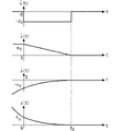
- FIG. 5 is a diagram showing an example of running patterns generated by the constant jerk pattern generator 32 according to the first embodiment.
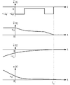
- FIG. 6 is a diagram showing an example of a running pattern generated by the correction pattern generator 33 according to the first embodiment.
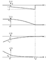
- FIG. 7 is a diagram showing an example of running patterns generated by the first pattern generation unit 28 according to the first embodiment.
- FIG. 5 shows an example of a running pattern with constant jerk generated by the constant jerk pattern generator 32 .
- the car 6 travels a distance x' 0 [m] within the landing time T' 0 [s] after passing the starting position and then stops.
- the landing time T' 0 [s] is expressed by the following formula (4), like formula (2).
- the traveling distance x' 0 [m] of the car 6 is represented by the following equation (5).
- the running pattern x_ref_ar11 generated by the constant jerk pattern generator 32 is expressed by the following equation (6) as a cubic function of time t[s].
- FIG. 6 shows an example of a running pattern generated by the correction pattern generator 33 for correcting the landing error in Equation (7).
- the car 6 moves by a distance -x' 0 [m] within the landing time T' 0 [s] of the traveling pattern generated by the constant jerk pattern generating section 32. Stop after running.
- the period until the landing time T' 0 [s] elapses is divided into three periods: a first period, a second period, and a third period.
- the first period is a period from when the car 6 passes the starting point until 1/4 of the landing time T' 0 [s] has passed.
- the second period is a period from after the first period until 1/2 of the landing time T' 0 [s] has elapsed.
- the third period is a period from after the second period until 1/4 of the landing time T' 0 [s] has passed.
- the integrated value of jerk over time T' 0 [s] is zero.
- the jerk is set to a piecewise constant value.
- jerk is set to a constant value in each of the first period, second period, and third period.
- the direction of the jerk in the first period is set in the direction of compensating the landing error.
- the direction of the jerk in the second period is set to the opposite direction of the jerk in the first period.
- the direction of the jerk in the third period is set in the same direction as the jerk in the first period.
- the absolute values of jerk in each of the first period, second period, and third period are set to the same magnitude.
- the integrated value of acceleration over time T' 0 [s] is zero.
- the acceleration is set to 0 at the timing when the car 6 passes the starting position.
- the speed at the timing when the car 6 passes the starting position is set to zero.
- the running pattern x_ref_ar12 generated by the correction pattern generation unit 33 in the first period is expressed by the following equation (8) as a cubic function of the time t[s].
- the absolute value Je [m/s 3 ] of the jerk in the first period, the second period, and the third period means that the car 6 reaches the distance -x' before the landing time T' 0 [s] elapses. It is set to run only 0 [m].
- the jerk absolute value J e [m/s 3 ] is expressed by the following equation (9).
- the running pattern x_ref_ar12 generated by the correction pattern generation unit 33 in the second period is expressed by the following equation (10) as a cubic function of the time t[s].
- the running pattern x_ref_ar12 generated by the correction pattern generation unit 33 in the third period is expressed by the following equation (11) as a cubic function of the time t[s].
- FIG. 7 shows an example of the running pattern generated by the first pattern generating section 28.
- the first pattern generation unit 28 superimposes the running pattern x_ref_ar11 generated by the constant jerk pattern generation unit 32 and the running pattern x_ref_ar12 generated by the correction pattern generation unit 33 . That is, the position x_ref_ar1 of the car 6 in the travel pattern generated by the first pattern generator 28 is expressed by the following equation (12) as a function of the time t[s].
- the acceleration, speed, and position of the car 6 before and after the control mode is switched from the inter-floor traveling mode to the floor landing mode, and between the floor landing modes. continuity is maintained. Therefore, vibration of the car 6 during landing control is less likely to be induced.
- the running distance between the landing modes in the running pattern generated by the first pattern generation unit 28 is x 0 [m]. .
- the landing time of the running pattern generated by the first pattern generating section 28 matches the landing time T' 0 [s] of the running pattern generated by the constant jerk pattern generating section 32 .
- FIG. 8 is a diagram showing an example of running patterns generated by the second pattern generator 29 according to the first embodiment.
- the second pattern generator 29 generates a running pattern in which the absolute value of jerk increases as a linear function of time until the car 6 stops.
- the jerk which is the time differential of the jerk, is kept constant until the car 6 stops.
- the travel pattern is set by two parameters: jerk- ⁇ [m/s 3 ] at the timing when the car 6 passes the starting position and jerk- ⁇ [m/s 3 ] at the timing when the car 6 stops. That is, there is one more parameter for a running pattern with constant jerk.
- the travel distance x 0 [m ] is determined, the landing time T′′ 0 [s] and two parameters ⁇ [m/s 3 ] and ⁇ [m/s 3 ] are uniquely determined.
- the position of the car 6 is x 0 [m], which is the position of the detector 14 provided at the origin position corresponding to the landing position on the destination floor. That is, the distance traveled by the car 6 until it stops must be x 0 [m] so that no floor landing error occurs.
- the acceleration of the car 6 at the timing when the car 6 passes the starting position is a constant value a 0 [m/s 2 ].
- the speed of the car 6 at this timing is the speed ⁇ v s [m/s] acquired by the sample hold 27 . From this condition, the implantation time T′′ 0 [s] and the two parameters ⁇ [m/s 3 ] and ⁇ [m/s 3 ] are expressed by the following equations (13) to (15) .
- the position x_ref_ar2 of the car 6 in the travel pattern generated by the second pattern generation unit 29 is expressed by the following equation (16) as a quartic function of the time t[s].
- the acceleration, speed, and position of the car 6 are changed before and after the control mode is switched from the inter-floor traveling mode to the floor landing mode, and between the floor landing modes. continuity is maintained. Therefore, vibration of the car 6 during landing control is less likely to be induced. Further, since the travel distance in the travel pattern generated by the second pattern generator 29 matches the distance x 0 [m] between the starting point position and the landing position, no landing error occurs.
- FIG. 9 is a diagram showing the relationship between the landing time and the speed of the car 6 in the running pattern generated by the pattern generator according to the first embodiment.
- FIG. 10 is a diagram showing an example of running patterns generated by the first pattern generator 28 according to the first embodiment.
- 11A and 11B are diagrams showing examples of running patterns generated by the first pattern generation unit 28 according to Embodiment 1.
- FIG. 9 is a diagram showing the relationship between the landing time and the speed of the car 6 in the running pattern generated by the pattern generator according to the first embodiment.
- FIG. 10 is a diagram showing an example of running patterns generated by the first pattern generator 28 according to the first embodiment.
- 11A and 11B are diagrams showing examples of running patterns generated by the first pattern generation unit 28 according to Embodiment 1.
- the vertical axis represents the landing time T′ 0 in each travel pattern with respect to the landing time T 0 [s] when there is no error in the current position of the car 6 detected by the position measuring unit 10 . [s] or the ratio of T'' 0 [s].
- of the actual speed of the car 6 acquired by the sample hold 27 at the timing when the car 6 passes the starting position is referred to as the first speed.
- of the velocity at the timing when the car 6 passes the starting position when the current position of the car 6 detected by the position measuring unit 10 is assumed to be the second velocity.
- the horizontal axis represents the ratio of the first speed
- the dashed line graph represents the relationship of the running patterns generated by the first pattern generator 28 .
- the solid line graph represents the relationship of the running patterns generated by the second pattern generator 29 .
- the starting position x 0 [m] and the acceleration a 0 [m/s 2 ] of the car 6 when passing through the starting position are fixed to preset values.
- Landing time T' 0 [s] in the running pattern generated by the first pattern generator 28 is represented by equation (4). Therefore, from equation (2), the landing time ratio T' 0 /T 0 monotonically increases with an increase in the velocity ratio
- the landing time T' 0 [s] in the running pattern generated by the second pattern generator 29 is represented by Equation (13). Therefore, from equation (2), the landing time ratio T' 0 /T 0 monotonically decreases as the velocity ratio
- the landing instruction unit 17 includes a first pattern generation unit 28 and a second pattern generation unit 29 as a plurality of pattern generation units. Therefore, the pattern selection unit 30 selects the running pattern that shortens the landing time from the running patterns generated by the first pattern generating unit 28 and the second pattern generating unit 29 .
- the pattern selection unit 30 generates the running pattern generated by the first pattern generation unit 28 when the first speed
- the pattern selection unit 30 generates the running pattern generated by the second pattern generation unit 29 when the first speed
- the landing time until the car 6 stops is maintained at a constant jerk until the car 6 stops, regardless of the magnitude of the first speed
- the continuity of acceleration and the like is maintained in the travel patterns generated by any of the pattern generators, deterioration of riding comfort due to vibration of the car 6 can be suppressed.
- the running pattern generated by the first pattern generator 28 is indicated by a solid line. Also, the running pattern in FIG. 2, in which a constant jerk is maintained until the car 6 stops, is indicated by a dashed line. From this figure, when the first speed
- the running pattern generated by the second pattern generator 29 is indicated by a solid line.
- the running pattern in FIG. 2, in which a constant jerk is maintained until the car 6 stops is indicated by a dashed line. From this figure, when the first speed
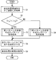
- FIG. 12 to 14 are flowcharts showing an example of the operation of the control system 8 according to Embodiment 1.
- FIG. 12 to 14 are flowcharts showing an example of the operation of the control system 8 according to Embodiment 1.
- FIG. 12 shows an example of processing of the control system 8 relating to landing control to the landing position.
- the process of FIG. 12 is started when the origin detection unit 11 detects that the car 6 has passed the origin position.
- step S1 the sample hold 27 of the landing command unit 17 acquires the velocity v s [m/s] of the car 6 when the car 6 passes the starting position. After that, the control system 8 proceeds to the processing of step S2.
- step S2 the pattern selector 30 determines whether the first speed
- step S3 the first pattern generation unit 28 performs running pattern generation processing. After that, the control system 8 proceeds to the processing of step S5.
- step S4 the second pattern generation unit 29 performs running pattern generation processing. After that, the control system 8 proceeds to the processing of step S5.
- step S5 the running control unit 19 causes the car 6 to follow the generated running pattern and stop at the landing position. After that, the control system 8 proceeds to the processing of step S6.
- step S6 the control system 8 acquires the difference between the stop position and the landing position of the car 6 after the car 6 stops.
- the difference acquired here is used as information for determining the landing motion. After that, the control system 8 ends the process related to the landing control.
- FIG. 13 shows an example of the running pattern generation processing of the first pattern generation unit 28 in step S3 of FIG.
- step S31 the constant jerk pattern generator 32 calculates the coefficients in the formula for the running pattern with constant jerk. At this time, the constant jerk pattern generator 32 calculates the traveling distance x' 0 [m] and the landing time T' 0 [s] of the car 6 . After that, the first pattern generator 28 proceeds to the process of step S32.
- step S32 the correction pattern generator 33 calculates the coefficients in the formula of the running pattern for correcting the landing error xe [m] within the landing time T'0 [s]. After that, the first pattern generator 28 proceeds to the process of step S33.
- step S ⁇ b>33 the first pattern generation unit 28 calculates the number of times n of processing during traveling from passing the starting position to the landing position.
- the first pattern generator 28 calculates the number of times of processing n as a natural number n obtained by dividing the landing time T' 0 [s] by the calculation period T s [s].
- the first pattern generator 28 initializes the loop variable k to zero. After that, the first pattern generator 28 proceeds to the process of step S34.
- step S34 the first pattern generation unit 28 adds 1 to the loop variable k.
- step S35 the constant jerk pattern generator 32 calculates the position x1(k) of the car 6 at the k-th time point of the generated running pattern.
- step S36 the correction pattern generator 33 calculates the position x2(k) of the car 6 at the k-th time of the generated running pattern.
- step S37 the adder 34 adds the position x1(k) and the position x2(k) to obtain the position of the car 6 at the position of the k-th time point of the travel pattern generated by the first pattern generator 28. Output as position x(k).
- step S38 the first pattern generation unit 28 determines whether the loop variable k is equal to or greater than the number of times of processing n. If the determination result is No, the first pattern generator 28 proceeds to the process of step S34. On the other hand, if the determination result is Yes, the first pattern generation unit 28 ends the running pattern generation processing.
- FIG. 14 shows an example of the running pattern generation processing of the second pattern generation unit 29 in step S4 of FIG.
- step S41 the second pattern generator 29 calculates the coefficient in the formula of the running pattern in which the absolute value of jerk increases as a linear function of time. At this time, the second pattern generator 29 calculates the landing time T'' 0 [s]. After that, the second pattern generator 29 proceeds to the process of step S42.
- step S42 the second pattern generation unit 29 calculates the number of times n of processing during traveling from passing the starting position to the landing position.
- the second pattern generator 29 calculates the number of times of processing n as a natural number n obtained by dividing the landing time T′′ 0 [s] by the calculation period T s [s].
- the second pattern generator 29 initializes the loop variable k to zero. After that, the second pattern generator 29 proceeds to the process of step S43.
- step S43 the second pattern generation unit 29 adds 1 to the loop variable k.
- step S44 the second pattern generator 29 calculates the position x(k) of the car 6 at the k-th time point of the generated running pattern.
- step S45 the second pattern generator 29 outputs the calculated x(k).
- step S46 the second pattern generation unit 29 determines whether the loop variable k is equal to or greater than the number of times of processing n. If the determination result is No, the second pattern generation unit 29 proceeds to the process of step S43. On the other hand, if the determination result is Yes, the second pattern generation unit 29 ends the running pattern generation processing.
- control system 8 may include three or more pattern generators.
- the pattern generator may generate a running pattern in which the relationship between jerk and time is defined by a step function or other function such as a linear function. At this time, the function is selected, for example, a function set by two or more parameters. Also, each pattern generator may output a velocity waveform instead of outputting a position waveform. At this time, the control system 8 can also be applied to the elevator 1 that performs landing control based on speed control.
- the position measurement unit 10 does not have to be an APS sensor.
- the position measuring unit 10 may detect the position of the car 6 by using, for example, a governor.
- the control system 8 includes the position measurement unit 10, the starting point detection unit 11, a plurality of pattern generation units, the travel control unit 19, and the pattern selection unit 30.
- the position measuring unit 10 detects the current position of the car 6 in the running direction.
- the starting point detection unit 11 detects passage of the car 6 at a starting point position that is a preset distance away from the landing position of the car 6 .
- Each pattern generator generates a running pattern from the starting position to the landing position based on different algorithms. In each travel pattern, the acceleration is continuous from before the car 6 passes the starting position until the car 6 stops.
- the travel control unit 19 Based on the current position of the car 6 detected by the position measuring unit 10, the travel control unit 19 causes the travel of the car 6 to follow the travel pattern generated by one of the pattern generation units.
- the pattern selection unit 30 selects the running pattern with the shortest landing time from among the running patterns generated by the respective pattern generating units as the running pattern for the running control unit 19 to follow the running of the car 6 .
- Landing time is the time required for running from the starting position to the landing position.
- the pattern selection unit 30 performs the selection based on the speed of the car 6 at the timing when the starting point detection unit 11 detects passage of the car 6 .
- the control method of the elevator 1 according to Embodiment 1 includes a starting point detection process, a speed acquisition process, a pattern selection process, and a travel control process.
- the starting point detection step is a step of detecting passage of the car 6 at the starting point position.
- the speed obtaining step is a step of obtaining the speed of the car 6 at the timing when passage of the car 6 through the starting point position is detected in the starting point detecting step.
- the pattern selection step is a step of selecting a driving pattern with the shortest landing time from among a plurality of driving patterns based on mutually different algorithms.
- Each running pattern is a running pattern from the starting position to the landing position.
- the acceleration is continuous from before the car 6 passes the starting position until the car 6 stops.
- selection selection is made based on the speed of the car 6 obtained in the speed obtaining step.
- the travel control step is a step of causing the travel of the car 6 to follow the travel pattern selected in the pattern selection step based on the current position of the car 6 .
- the running of the car 6 is controlled so that acceleration is maintained continuously from just before passing the starting point until the car 6 stops. Therefore, vibration of the car 6 is less likely to be induced, and deterioration of ride comfort during floor landing control can be suppressed. Further, since the traveling pattern with the shortest landing time is selected from among the plurality of traveling patterns, convenience for the user of the elevator 1 is improved. In other words, it is possible to suppress deterioration of ride comfort for the user and improve convenience.
- the control system 8 also includes a first pattern generator 28 as a pattern generator.
- the first pattern generator 28 generates a running pattern by superimposing the constant jerk pattern and the correction pattern.
- the constant jerk pattern is a travel pattern in which the initial speed is the speed of the car 6 at the timing when the starting point detection unit 11 detects the passage of the car 6, and a constant jerk is maintained until the car 6 stops.
- the correction pattern is a running pattern for correcting the landing error due to the constant jerk pattern within the landing time of the constant jerk pattern.
- a running pattern in which the landing error is corrected is generated based on a running pattern with a constant jerk that provides a comfortable ride for the user. Therefore, it is possible to more effectively suppress the deterioration of ride comfort for the user and improve convenience.
- the control system 8 also includes a second pattern generator 29 as a pattern generator.
- the second pattern generation unit 29 generates a traveling pattern in which the absolute value of jerk increases as a linear function of time until the car 6 stops, according to the speed of the car 6 at the timing when the starting point detection unit 11 detects passage of the car 6. to generate
- the absolute value of the speed of the car 6 at the timing when the starting point detection unit 11 detects passage of the car 6 is defined as the first speed.
- the absolute value of the speed of the car 6 at the starting position when there is no error in the current position of the car 6 measured by the position measuring unit 10 is defined as the second speed.
- the pattern selection unit 30 selects the running pattern generated by the first pattern generation unit 28 when the first speed is lower than the second speed.
- the pattern selection unit 30 selects the running pattern generated by the second pattern generation unit 29 when the first speed is higher than the second speed.
- the relationship between the second speed and the landing time is represented by a formula using elementary functions such as formula (4) and formula (13). be. Therefore, the condition for determining which driving pattern has the shortest landing time is a condition that can be set in advance based on these equations. In this example, which driving pattern has the shortest landing time can be determined from the magnitude relationship between the first speed and the second speed. Therefore, at the timing when the car 6 passes the starting position, the pattern selecting section 30 can quickly determine which running pattern has the short landing time based on the speed of the car 6 at that timing. This reduces the time lag associated with the selection of the driving pattern. Therefore, it is possible to more effectively achieve both suppression of deterioration in ride comfort for the user and improvement in convenience.
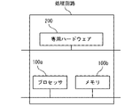
- FIG. 15 is a hardware configuration diagram of main parts of the control system 8 according to the first embodiment.
- the processing circuitry comprises at least one processor 100a and at least one memory 100b.
- the processing circuitry may include at least one piece of dedicated hardware 200 in conjunction with, or as an alternative to, processor 100a and memory 100b.
- each function of the control system 8 is realized by software, firmware, or a combination of software and firmware. At least one of software and firmware is written as a program.
- the program is stored in memory 100b.
- the processor 100a realizes each function of the control system 8 by reading and executing the programs stored in the memory 100b.
- the processor 100a is also called a CPU (Central Processing Unit), a processing device, an arithmetic device, a microprocessor, a microcomputer, or a DSP.
- the memory 100b is composed of, for example, nonvolatile or volatile semiconductor memory such as RAM, ROM, flash memory, EPROM, and EEPROM.
- the processing circuit may be implemented, for example, as a single circuit, multiple circuits, a programmed processor, a parallel programmed processor, an ASIC, an FPGA, or a combination thereof.
- Each function of the control system 8 can be implemented by a processing circuit. Alternatively, each function of the control system 8 can be collectively realized by a processing circuit. A part of each function of the control system 8 may be realized by dedicated hardware 200 and the other part may be realized by software or firmware. Thus, the processing circuitry implements each function of control system 8 in dedicated hardware 200, software, firmware, or a combination thereof.
- Embodiment 2 In the second embodiment, the differences from the example disclosed in the first embodiment will be described in detail. Any feature of the example disclosed in the first embodiment may be employed for features not described in the second embodiment.
- FIG. 16 is a configuration diagram of the elevator 1 according to the second embodiment.
- control system 8 of the elevator 1 does not include the position measuring section 10.
- the control system 8 includes a car state estimating section 35 instead of the position measuring section 10 .
- the car state estimation unit 35 is a part that estimates the state of the car 6.
- the car state estimation unit 35 is mounted on the control device 12 .
- the state of the car 6 estimated by the car state estimating unit 35 includes the current position of the car 6 in the running direction, the speed of the car 6, and the like.
- the car state estimation unit 35 is a part that detects the current position of the car 6 in the traveling direction by estimation.
- the car state estimator 35 is an example of a position detector.
- the car state estimator 35 estimates the current position of the car 6 based on the signal received from the encoder 9 .
- the car state estimator 35 outputs the detected current position x_car of the car 6 to the subtractor 24 of the control device 12 .
- the car state estimator 35 also estimates the speed of the car 6 by, for example, time differentiation of the current position of the car 6 .
- the car state estimation unit 35 outputs a signal of the estimated speed v_car of the car 6 to the landing command unit 17 of the control device 12 .
- the car state estimating section 35 may be omitted in the elevator 1 whose ascending/descending process is so short that the transfer characteristics to the car 6 through the motor 3, the sheaves 4, and the main ropes 5 can be ignored.
- the control system 8 may include the car speed calculator 15 instead of the car state estimator 35 .
- the state estimator is configured by, for example, a secondary filter.
- the running of the car 6 is controlled so that acceleration is maintained continuously from just before passing the starting point until the car 6 stops. Therefore, vibration of the car 6 is less likely to be induced, and deterioration of ride comfort during floor landing control can be suppressed. Further, since the traveling pattern with the shortest landing time is selected from among the plurality of traveling patterns, convenience for the user of the elevator 1 is improved. In other words, it is possible to suppress deterioration of ride comfort for the user and improve convenience.
- control system and control method according to the present disclosure can be applied to elevators.
Landscapes
- Engineering & Computer Science (AREA)
- Automation & Control Theory (AREA)
- Computer Networks & Wireless Communication (AREA)
- Elevator Control (AREA)
Abstract
Description
図1は、実施の形態1に係るエレベーター1の構成図である。
図2は、実施の形態1に係る制御システム8における走行パターンの例を示す図である。



図5は、実施の形態1に係る定ジャークパターン生成部32が生成する走行パターンの例を示す図である。
図6は、実施の形態1に係る補正パターン生成部33が生成する走行パターンの例を示す図である。
図7は、実施の形態1に係る第1パターン生成部28が生成する走行パターンの例を示す図である。









図8は、実施の形態1に係る第2パターン生成部29が生成する走行パターンの例を示す図である。




図9は、実施の形態1に係るパターン生成部が生成する走行パターンにおける着床時間およびかご6の速度の関係を示す図である。
図10は、実施の形態1に係る第1パターン生成部28が生成する走行パターンの例を示す図である。
図11は、実施の形態1に係る第1パターン生成部28が生成する走行パターンの例を示す図である。
図12から図14は、実施の形態1に係る制御システム8の動作の例を示すフローチャートである。
図12の処理は、起点検知部11がかご6の起点位置の通過を検知するときに開始される。
また、実施の形態1に係るエレベーター1の制御方法は、起点検知工程と、速度取得工程と、パターン選択工程と、走行制御工程と、を備える。起点検知工程は、起点位置におけるかご6の通過を検知する工程である。速度取得工程は、起点検知工程でかご6の起点位置の通過が検知されたタイミングにおけるかご6の速度を取得する工程である。パターン選択工程は、互いに異なるアルゴリズムに基づく複数の走行パターンのうちから、着床時間が最も短い走行パターンを選択する工程である。各々の走行パターンは、起点位置から着床位置までの走行パターンである。各々の走行パターンにおいて、かご6が起点位置を通過する前からかご6が停止するまで加速度が連続である。パターン選択工程において、速度取得工程で取得されたかご6の速度に基づいて選択が行われる。走行制御工程は、かご6の現在位置に基づいて、パターン選択工程において選択された走行パターンにかご6の走行を追従させる工程である。
図15は、実施の形態1に係る制御システム8の主要部のハードウェア構成図である。
実施の形態2において、実施の形態1で開示される例と相違する点について特に詳しく説明する。実施の形態2で説明しない特徴については、実施の形態1で開示される例のいずれの特徴が採用されてもよい。
Claims (5)
- かごの走行方向における現在位置を検出する位置検出部と、
前記かごの着床位置から予め設定された距離離れた起点位置における前記かごの通過を検知する起点検知部と、
前記起点位置から前記着床位置までの前記かごが前記起点位置を通過する前から前記かごが停止するまで加速度が連続な走行パターンを、互いに異なるアルゴリズムに基づいて各々が生成する複数のパターン生成部と、
前記位置検出部が検出する前記かごの現在位置に基づいて、前記かごの走行を前記複数のパターン生成部のいずれかが生成した走行パターンに追従させる走行制御部と、
前記複数のパターン生成部の各々が生成する走行パターンのうちから、前記起点検知部が前記かごの通過を検知したタイミングにおける前記かごの速度に基づいて、前記起点位置から前記着床位置までの走行に要する着床時間が最も短い走行パターンを、前記走行制御部が前記かごの走行を追従させる走行パターンとして選択するパターン選択部と、
を備えるエレベーターの制御システム。 - 前記複数のパターン生成部は、前記起点検知部が前記かごの通過を検知したタイミングにおける前記かごの速度を初速度とし前記かごが停止するまで一定のジャークを保つパターン、および当該パターンによる着床誤差を当該パターンにおける着床時間のうちに補正するパターンを重ね合わせた走行パターンを生成する第1パターン生成部を含む
請求項1に記載のエレベーターの制御システム。 - 前記複数のパターン生成部は、前記起点検知部が前記かごの通過を検知したタイミングにおける前記かごの速度に応じて、前記かごが停止するまでジャークの絶対値が時間の一次関数として増加する走行パターンを生成する第2パターン生成部を含む
請求項1または請求項2に記載のエレベーターの制御システム。 - 前記複数のパターン生成部は、
前記起点検知部が前記かごの通過を検知したタイミングにおける前記かごの速度を初速度とし前記かごが停止するまで一定のジャークを保つパターン、および当該パターンによる着床誤差を当該パターンにおける着床時間のうちに補正するパターンを重ね合わせた走行パターンを生成する第1パターン生成部と、
前記起点検知部が前記かごの通過を検知したタイミングにおける前記かごの速度に応じて、前記かごが停止するまでジャークの絶対値が時間の一次関数として増加する走行パターンを生成する第2パターン生成部と、
を含み、
前記パターン選択部は、前記起点検知部が前記かごの通過を検知したタイミングにおける前記かごの速度の絶対値を第1速度とし、前記位置検出部が検出する前記かごの現在位置に誤差がないとした場合の前記起点位置における前記かごの速度の絶対値を第2速度とし、前記第1速度が前記第2速度より小さい場合に前記第1パターン生成部が生成する走行パターンを選択し、前記第1速度が前記第2速度より大きい場合に前記第2パターン生成部が生成する走行パターンを選択する
請求項1に記載のエレベーターの制御システム。 - かごの着床位置から予め設定された距離離れた起点位置における前記かごの通過を検知する起点検知工程と、
前記起点検知工程で前記かごの前記起点位置の通過が検知されたタイミングにおける前記かごの速度を取得する速度取得工程と、
前記起点位置から前記着床位置までの、前記かごが前記起点位置を通過する前から前記かごが停止するまで加速度が連続な、互いに異なるアルゴリズムに基づく複数の走行パターンのうちから、前記速度取得工程において取得された前記かごの速度に基づいて、前記起点位置から前記着床位置までの走行に要する着床時間が最も短い走行パターンを選択するパターン選択工程と、
前記かごの現在位置に基づいて、前記パターン選択工程において選択された走行パターンに前記かごの走行を追従させる走行制御工程と、
を備えるエレベーターの制御方法。
Priority Applications (4)
| Application Number | Priority Date | Filing Date | Title |
|---|---|---|---|
| US18/276,882 US20240116736A1 (en) | 2021-04-12 | 2021-04-12 | Elevator control system and method for controlling elevator |
| JP2023514193A JP7452760B2 (ja) | 2021-04-12 | 2021-04-12 | エレベーターの制御システムおよびエレベーターの制御方法 |
| PCT/JP2021/015193 WO2022219682A1 (ja) | 2021-04-12 | 2021-04-12 | エレベーターの制御システムおよびエレベーターの制御方法 |
| CN202180096351.5A CN117177929A (zh) | 2021-04-12 | 2021-04-12 | 电梯的控制系统以及电梯的控制方法 |
Applications Claiming Priority (1)
| Application Number | Priority Date | Filing Date | Title |
|---|---|---|---|
| PCT/JP2021/015193 WO2022219682A1 (ja) | 2021-04-12 | 2021-04-12 | エレベーターの制御システムおよびエレベーターの制御方法 |
Publications (1)
| Publication Number | Publication Date |
|---|---|
| WO2022219682A1 true WO2022219682A1 (ja) | 2022-10-20 |
Family
ID=83640253
Family Applications (1)
| Application Number | Title | Priority Date | Filing Date |
|---|---|---|---|
| PCT/JP2021/015193 Ceased WO2022219682A1 (ja) | 2021-04-12 | 2021-04-12 | エレベーターの制御システムおよびエレベーターの制御方法 |
Country Status (4)
| Country | Link |
|---|---|
| US (1) | US20240116736A1 (ja) |
| JP (1) | JP7452760B2 (ja) |
| CN (1) | CN117177929A (ja) |
| WO (1) | WO2022219682A1 (ja) |
Citations (5)
| Publication number | Priority date | Publication date | Assignee | Title |
|---|---|---|---|---|
| US4691807A (en) * | 1986-03-05 | 1987-09-08 | Mitsubishi Denki Kabushiki Kaisha | Elevator control apparatus |
| JPH02239076A (ja) * | 1989-03-09 | 1990-09-21 | Toshiba Corp | エレベータ制御装置 |
| JP2007254050A (ja) * | 2006-03-20 | 2007-10-04 | Toshiba Elevator Co Ltd | エレベータの着床制御装置 |
| WO2011030402A1 (ja) * | 2009-09-09 | 2011-03-17 | 三菱電機株式会社 | エレベータの制御装置 |
| JP2011153020A (ja) * | 2010-01-28 | 2011-08-11 | Mitsubishi Electric Corp | エレベータの速度制御装置 |
Family Cites Families (9)
| Publication number | Priority date | Publication date | Assignee | Title |
|---|---|---|---|---|
| US3785463A (en) * | 1972-05-09 | 1974-01-15 | Reliance Electric Co | Final stopping control |
| US3774729A (en) * | 1972-05-17 | 1973-11-27 | Westinghouse Electric Corp | Speed pattern generator for elevator systems |
| US4261439A (en) * | 1979-09-10 | 1981-04-14 | Westinghouse Electric Corp. | Elevator system |
| US4570755A (en) * | 1983-06-27 | 1986-02-18 | Armor Electric Company, Inc. | Digital landing computer for elevator |
| JPH1053378A (ja) * | 1996-06-07 | 1998-02-24 | Otis Elevator Co | エレベータの速度制御回路 |
| WO1997047551A1 (fr) * | 1996-06-12 | 1997-12-18 | Kabushiki Kaisha Toshiba | Dispositif pour commander la vitesse d'un ascenseur |
| GB2476590B (en) * | 2008-08-04 | 2013-01-09 | Otis Elevator Co | Elevator motion profile control |
| WO2018002241A1 (en) * | 2016-06-30 | 2018-01-04 | Inventio Ag | Elevator ride quality enhancement by drive cycle optimization |
| JP7374398B1 (ja) * | 2021-12-17 | 2023-11-06 | 三菱電機株式会社 | 提示情報生成装置、および、提示情報生成方法 |
-
2021
- 2021-04-12 JP JP2023514193A patent/JP7452760B2/ja active Active
- 2021-04-12 CN CN202180096351.5A patent/CN117177929A/zh active Pending
- 2021-04-12 US US18/276,882 patent/US20240116736A1/en active Pending
- 2021-04-12 WO PCT/JP2021/015193 patent/WO2022219682A1/ja not_active Ceased
Patent Citations (5)
| Publication number | Priority date | Publication date | Assignee | Title |
|---|---|---|---|---|
| US4691807A (en) * | 1986-03-05 | 1987-09-08 | Mitsubishi Denki Kabushiki Kaisha | Elevator control apparatus |
| JPH02239076A (ja) * | 1989-03-09 | 1990-09-21 | Toshiba Corp | エレベータ制御装置 |
| JP2007254050A (ja) * | 2006-03-20 | 2007-10-04 | Toshiba Elevator Co Ltd | エレベータの着床制御装置 |
| WO2011030402A1 (ja) * | 2009-09-09 | 2011-03-17 | 三菱電機株式会社 | エレベータの制御装置 |
| JP2011153020A (ja) * | 2010-01-28 | 2011-08-11 | Mitsubishi Electric Corp | エレベータの速度制御装置 |
Also Published As
| Publication number | Publication date |
|---|---|
| JPWO2022219682A1 (ja) | 2022-10-20 |
| CN117177929A (zh) | 2023-12-05 |
| US20240116736A1 (en) | 2024-04-11 |
| JP7452760B2 (ja) | 2024-03-19 |
Similar Documents
| Publication | Publication Date | Title |
|---|---|---|
| KR102044340B1 (ko) | 엘리베이터의 제어 장치 및 가버너 로프 신축량 추정 방법 | |
| US7992689B2 (en) | Movement control of an elevator system using position deviation to determine loading state | |
| FI96674C (fi) | Menetelmä ja laite asennoittimen käyttimen säätelemiseen, erityisesti hissilaitteistoissa | |
| JP6490238B2 (ja) | エレベーターの制御装置 | |
| JP7452760B2 (ja) | エレベーターの制御システムおよびエレベーターの制御方法 | |
| JP2012056689A (ja) | エレベータ | |
| JP7700961B2 (ja) | かご位置制御装置 | |
| JP2012240796A (ja) | エレベータの制御装置 | |
| JP2005289627A (ja) | エレベータ | |
| JP2010180026A (ja) | エレベーターの制御装置 | |
| JP2005170537A (ja) | エレベータの制御装置 | |
| JP7121139B2 (ja) | エレベーター制御装置 | |
| JP2006193297A (ja) | エレベータ装置 | |
| WO2021240593A1 (ja) | エレベーターの着床制御システム | |
| JP2014001022A (ja) | エレベータおよびその速度制御方法 | |
| JP4216671B2 (ja) | エレベータ用秤装置の較正装置、及びエレベータ用秤装置の較正方法 | |
| CN117545706A (zh) | 用于适配电梯设备的对重的方法 | |
| JP5177850B2 (ja) | エレベータの着床制御装置 | |
| JP6611882B2 (ja) | エレベータの制御装置およびガバナロープ伸縮量推定方法 | |
| JP2609695B2 (ja) | エレベータの着床制御方法 | |
| JP2004010345A (ja) | エレベーター装置 | |
| US20250051130A1 (en) | Method for determining a lead torque of an elevator system | |
| JP5029799B2 (ja) | エレベータの着床制御装置 | |
| KR102205550B1 (ko) | 엘리베이터의 제어 장치 및 권상 로프의 신축량 추정 방법 | |
| JPH07298686A (ja) | エレベータ用インバータの速度制御装置 |
Legal Events
| Date | Code | Title | Description |
|---|---|---|---|
| 121 | Ep: the epo has been informed by wipo that ep was designated in this application |
Ref document number: 21936885 Country of ref document: EP Kind code of ref document: A1 |
|
| WWE | Wipo information: entry into national phase |
Ref document number: 18276882 Country of ref document: US |
|
| WWE | Wipo information: entry into national phase |
Ref document number: 2023514193 Country of ref document: JP |
|
| NENP | Non-entry into the national phase |
Ref country code: DE |
|
| 122 | Ep: pct application non-entry in european phase |
Ref document number: 21936885 Country of ref document: EP Kind code of ref document: A1 |