WO2022215415A1 - Heat exchanger - Google Patents
Heat exchanger Download PDFInfo
- Publication number
- WO2022215415A1 WO2022215415A1 PCT/JP2022/009951 JP2022009951W WO2022215415A1 WO 2022215415 A1 WO2022215415 A1 WO 2022215415A1 JP 2022009951 W JP2022009951 W JP 2022009951W WO 2022215415 A1 WO2022215415 A1 WO 2022215415A1
- Authority
- WO
- WIPO (PCT)
- Prior art keywords
- coolant
- plate member
- refrigerant
- plate
- heat exchanger
- Prior art date
Links
- 239000003507 refrigerant Substances 0.000 claims abstract description 111
- 238000004891 communication Methods 0.000 claims abstract description 28
- 239000012530 fluid Substances 0.000 claims abstract description 9
- 238000000638 solvent extraction Methods 0.000 claims abstract description 6
- 239000002826 coolant Substances 0.000 claims description 118
- 238000005192 partition Methods 0.000 claims description 13
- 239000000498 cooling water Substances 0.000 description 51
- 239000007791 liquid phase Substances 0.000 description 18
- 239000007788 liquid Substances 0.000 description 16
- 239000012071 phase Substances 0.000 description 13
- 238000004781 supercooling Methods 0.000 description 11
- 230000005494 condensation Effects 0.000 description 8
- 238000009833 condensation Methods 0.000 description 8
- 238000000926 separation method Methods 0.000 description 8
- 239000012808 vapor phase Substances 0.000 description 7
- XLYOFNOQVPJJNP-UHFFFAOYSA-N water Substances O XLYOFNOQVPJJNP-UHFFFAOYSA-N 0.000 description 6
- 230000000694 effects Effects 0.000 description 4
- 238000002474 experimental method Methods 0.000 description 4
- 230000000149 penetrating effect Effects 0.000 description 4
- 230000002093 peripheral effect Effects 0.000 description 4
- 238000012986 modification Methods 0.000 description 3
- 230000004048 modification Effects 0.000 description 3
- 238000005219 brazing Methods 0.000 description 2
- 238000010586 diagram Methods 0.000 description 2
- 238000005057 refrigeration Methods 0.000 description 2
- 238000012546 transfer Methods 0.000 description 2
- 239000000470 constituent Substances 0.000 description 1
- 238000001816 cooling Methods 0.000 description 1
- 238000013461 design Methods 0.000 description 1
- 238000003475 lamination Methods 0.000 description 1
Images


Classifications
-
- F—MECHANICAL ENGINEERING; LIGHTING; HEATING; WEAPONS; BLASTING
- F28—HEAT EXCHANGE IN GENERAL
- F28D—HEAT-EXCHANGE APPARATUS, NOT PROVIDED FOR IN ANOTHER SUBCLASS, IN WHICH THE HEAT-EXCHANGE MEDIA DO NOT COME INTO DIRECT CONTACT
- F28D9/00—Heat-exchange apparatus having stationary plate-like or laminated conduit assemblies for both heat-exchange media, the media being in contact with different sides of a conduit wall
- F28D9/02—Heat-exchange apparatus having stationary plate-like or laminated conduit assemblies for both heat-exchange media, the media being in contact with different sides of a conduit wall the heat-exchange media travelling at an angle to one another
-
- F—MECHANICAL ENGINEERING; LIGHTING; HEATING; WEAPONS; BLASTING
- F28—HEAT EXCHANGE IN GENERAL
- F28D—HEAT-EXCHANGE APPARATUS, NOT PROVIDED FOR IN ANOTHER SUBCLASS, IN WHICH THE HEAT-EXCHANGE MEDIA DO NOT COME INTO DIRECT CONTACT
- F28D9/00—Heat-exchange apparatus having stationary plate-like or laminated conduit assemblies for both heat-exchange media, the media being in contact with different sides of a conduit wall
- F28D9/0062—Heat-exchange apparatus having stationary plate-like or laminated conduit assemblies for both heat-exchange media, the media being in contact with different sides of a conduit wall the conduits for one heat-exchange medium being formed by spaced plates with inserted elements
- F28D9/0075—Heat-exchange apparatus having stationary plate-like or laminated conduit assemblies for both heat-exchange media, the media being in contact with different sides of a conduit wall the conduits for one heat-exchange medium being formed by spaced plates with inserted elements the plates having openings therein for circulation of the heat-exchange medium from one conduit to another
-
- F—MECHANICAL ENGINEERING; LIGHTING; HEATING; WEAPONS; BLASTING
- F28—HEAT EXCHANGE IN GENERAL
- F28F—DETAILS OF HEAT-EXCHANGE AND HEAT-TRANSFER APPARATUS, OF GENERAL APPLICATION
- F28F3/00—Plate-like or laminated elements; Assemblies of plate-like or laminated elements
- F28F3/02—Elements or assemblies thereof with means for increasing heat-transfer area, e.g. with fins, with recesses, with corrugations
- F28F3/04—Elements or assemblies thereof with means for increasing heat-transfer area, e.g. with fins, with recesses, with corrugations the means being integral with the element
-
- F—MECHANICAL ENGINEERING; LIGHTING; HEATING; WEAPONS; BLASTING
- F28—HEAT EXCHANGE IN GENERAL
- F28F—DETAILS OF HEAT-EXCHANGE AND HEAT-TRANSFER APPARATUS, OF GENERAL APPLICATION
- F28F3/00—Plate-like or laminated elements; Assemblies of plate-like or laminated elements
- F28F3/08—Elements constructed for building-up into stacks, e.g. capable of being taken apart for cleaning
-
- F—MECHANICAL ENGINEERING; LIGHTING; HEATING; WEAPONS; BLASTING
- F28—HEAT EXCHANGE IN GENERAL
- F28F—DETAILS OF HEAT-EXCHANGE AND HEAT-TRANSFER APPARATUS, OF GENERAL APPLICATION
- F28F9/00—Casings; Header boxes; Auxiliary supports for elements; Auxiliary members within casings
- F28F9/02—Header boxes; End plates
-
- F—MECHANICAL ENGINEERING; LIGHTING; HEATING; WEAPONS; BLASTING
- F28—HEAT EXCHANGE IN GENERAL
- F28F—DETAILS OF HEAT-EXCHANGE AND HEAT-TRANSFER APPARATUS, OF GENERAL APPLICATION
- F28F2250/00—Arrangements for modifying the flow of the heat exchange media, e.g. flow guiding means; Particular flow patterns
- F28F2250/06—Derivation channels, e.g. bypass
Definitions
- the present disclosure relates to heat exchangers.
- This heat exchanger has a plate stack and a gas-liquid separator.
- a plate laminate is configured by stacking a plurality of plate members.
- coolant channels through which coolant flows and cooling water channels through which cooling water flows are alternately arranged in the plate stacking direction.
- a coolant inflow connector and a coolant outflow connector are provided on one end surface of the plate stack in the plate stacking direction.
- a gas-liquid separator is provided on the other end surface of the plate stack in the plate stacking direction.
- the plate laminate is provided with a condensation section and a supercooling section.
- Vapor phase refrigerant flows into the condensing section through an inflow connector.
- heat is exchanged between the gas-phase refrigerant and the cooling water to generate a two-phase refrigerant in which the gas-phase refrigerant and the liquid-phase refrigerant are mixed.
- the two-phase refrigerant generated in the condensation section flows into the gas-liquid separation section and is separated into a gas-phase refrigerant and a liquid-phase refrigerant.
- the liquid-phase refrigerant separated in the condensing section flows into the supercooling section of the plate stack.
- the liquid-phase refrigerant is further cooled by heat exchange between the liquid-phase refrigerant and the cooling water.
- the liquid-phase refrigerant supercooled in the supercooling part is discharged to the outside through the outflow connector.
- the plate stack includes, as the plate members, a plurality of first plate members forming the condensation section and a plurality of second plate members forming the supercooling section.
- Each first plate member has an inflow portion for guiding the refrigerant that has flowed into the inflow connector into the first plate member, an outflow portion for guiding the refrigerant that has passed through the inside of the first plate member to the gas-liquid separation portion,
- a through-hole forming portion is also provided for guiding the refrigerant that has passed through the supercooling portion to the outflow connector.
- Each second plate member has an inflow portion for guiding the refrigerant flowing out of the gas-liquid separation portion into the second plate member, and an outflow portion for guiding the refrigerant that has passed through the inside of the second plate member to the outflow connector. and a through-hole forming portion for guiding the refrigerant that has passed through the condensing portion to the gas-liquid separating portion.
- An object of the present disclosure is to provide a heat exchanger capable of reducing pressure loss of refrigerant.
- a heat exchanger includes a plurality of plate members arranged in a stack to form a refrigerant flow path and a fluid flow path, and between a refrigerant flowing in the refrigerant flow path and a fluid flowing in the fluid flow path. is a heat exchanger in which heat is exchanged in The plate member has an inflow portion provided at one end of the coolant flow channel for allowing the coolant to flow into the coolant flow channel, and an inflow portion provided at the other end of the coolant flow channel to flow out the coolant that has flowed through the coolant flow channel.
- a partition wall is formed to separate the passage and the communication passage.
- part of the coolant flowing from the inflow portion to the coolant channel or part of the coolant flowing from the coolant channel to the outflow portion flows through the recess.
- pressure loss of the refrigerant can be reduced.
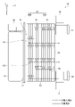
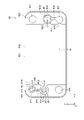
- FIG. 1 is a perspective view showing the perspective structure of the heat exchanger of the first embodiment.
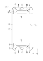
- FIG. 2 is a front view showing the front structure of the heat exchanger of the first embodiment.
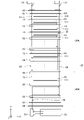
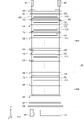
- FIG. 3 is a diagram schematically showing an exploded structure of the heat exchanger of the first embodiment.
- FIG. 4 is a diagram schematically showing an exploded structure of the heat exchanger of the first embodiment.
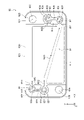
- FIG. 5 is a plan view showing the planar structure of the first outer plate of the first embodiment.
- FIG. 6 is a plan view showing the planar structure of the second outer plate of the first embodiment.
- FIG. 7 is a plan view showing the planar structure of the third outer plate of the first embodiment.
- FIG. 8 is a plan view showing the planar structure of the outer plate of the reference example.
- FIG. 1 is a perspective view showing the perspective structure of the heat exchanger of the first embodiment.
- FIG. 2 is a front view showing the front structure of the heat exchanger of the first embodiment.
- FIG. 3 is a diagram
- FIG. 9 is a plan view showing the planar structure of the first outer plate of the first modified example of the first embodiment.
- FIG. 10 is a plan view showing the planar structure of the first outer plate of the first modified example of the first embodiment.
- 11 is a plan view showing a planar structure of a first outer plate of a first modification of the first embodiment;
- FIG. 12 is an enlarged view showing the enlarged structure of the end portion of the first outer plate of the second embodiment.
- FIG. 13 is a graph showing the relationship between the width of the communication path and the number of repetitions of pressurization in the second embodiment.
- FIG. 14 is a graph showing the relationship between the rib width and the number of pressurization repetitions in the second embodiment.
- FIG. 1 An embodiment of a heat exchanger will be described below with reference to the drawings. In order to facilitate understanding of the description, the same constituent elements in each drawing are denoted by the same reference numerals as much as possible, and overlapping descriptions are omitted.
- This heat exchanger 10 is used, for example, as a condenser in the refrigeration cycle of a vehicle air conditioner.
- a refrigeration cycle is composed of a compressor, a condenser, an expansion valve, and an evaporator.
- a high-temperature and high-pressure vapor-phase refrigerant discharged from the compressor flows into the heat exchanger 10 .
- the heat exchanger 10 performs heat exchange between the high-temperature and high-pressure vapor-phase refrigerant and cooling water, thereby releasing the heat of the refrigerant to the cooling water and condensing the vapor-phase refrigerant.
- the heat exchanger 10 discharges the condensed liquid-phase refrigerant to the expansion valve.
- cooling water corresponds to the fluid.
- the heat exchanger 10 includes a core portion 20, a refrigerant inflow connector 30, a refrigerant outflow connector 31, a cooling water inflow connector 40, a cooling water outflow connector 41, a receiver connector 50, and a gas-liquid separator 51 .
- the core portion 20 is composed of a plurality of plates stacked in the direction indicated by the arrow Z in the figure. Hereinafter, the direction indicated by arrow Z will be referred to as "plate stacking direction Z".
- the core portion 20 includes a condensation portion 20A and a supercooling portion 20B.
- the condensation section 20A condenses the gas-phase refrigerant by exchanging heat between the gas-phase refrigerant discharged from the compressor and the cooling water in the core portion 20 .
- the supercooling section 20B is a section in the core section 20 that further cools the liquid-phase refrigerant by exchanging heat between the liquid-phase refrigerant flowing out of the gas-liquid separation section 51 and the cooling water.
- the gas-liquid separation section 51 is provided on one end face 21 of the core section 20 in the plate stacking direction Z.
- the gas-liquid separation section 51 is connected to the core section 20 via the receiver connector 50 .
- the gas-liquid separation section 51 separates the refrigerant flowing out of the condensation section 20A into a gas-phase refrigerant and a liquid-phase refrigerant, and flows the separated liquid-phase refrigerant to the supercooling section 20B.
- Each connector 30, 31, 40, 41 is provided on the other end surface 22 of the core portion 20 in the plate lamination direction Z.
- An inlet-side refrigerant pipe is connected to the refrigerant inflow connector 30 . Vapor-phase refrigerant discharged from the compressor flows into the condensing section 20A through the inlet-side refrigerant pipe and the refrigerant inflow connector 30 .
- An outlet-side refrigerant pipe is connected to the refrigerant outflow connector 31 .
- the liquid-phase refrigerant supercooled by the supercooling section 20B is discharged to the expansion valve through the refrigerant outflow connector 31 and the outlet-side refrigerant pipe.
- An inlet side cooling water pipe is connected to the cooling water inflow connector 40 .
- Cooling water flows into the core portion 20 through the inlet side cooling water pipe and the cooling water inflow connector 40 .
- An outlet-side cooling water pipe is connected to the cooling water outflow connector 41 .
- the cooling water that has exchanged heat with the refrigerant in the core portion 20 is discharged to the outside through the cooling water outflow connector 41 and the outlet side cooling water pipe.
- the core portion 20 includes a top plate 60, a top outer plate 61, a plurality of first outer plates 62, a plurality of first outer plates 62, and a top plate 60, which are stacked in the plate stacking direction Z, as portions constituting the condensation portion 20A. It comprises a first partitioning outer plate 63, a plurality of second outer plates 64, and an inner plate 70 arranged between the outer plates 61-64.
- the core portion 20 includes a second partitioning outer plate 65, a plurality of third outer plates 66, a bottom plate 67, and a bracket 68, which are stacked in the plate stacking direction Z, as portions constituting the supercooling portion 20B. and an inner plate 70 arranged between the outer plates 65 and 66 .
- these plates 61-66, 70 correspond to plate members.
- a gap formed between each of the outer plates 61 to 66 is partitioned into two independent spaces 80, 81 in the plate stacking direction Z by the inner plate 70.
- One space 80 constitutes a cooling water flow path through which cooling water flows.
- the other space 81 constitutes a coolant channel 81 through which coolant flows.
- the spaces 80 and 81 are hereinafter referred to as a "coolant flow path 80" and a "refrigerant flow path 81", respectively.
- Cooling water fins 110 are arranged in the cooling water flow path 80 to increase the heat transfer area for the cooling water.
- Coolant fins 111 are arranged in the coolant channel 81 to increase the heat transfer area for the coolant.
- the cooling water channel 80 corresponds to the fluid channel.
- Refrigerant tank holes 91 to 95 for circulating the refrigerant are formed in the core portion 20 .
- the left ends of the top plate 60, the top outer plate 61, and the plurality of first outer plates 62, and each of the plurality of inner plates 70 arranged between the outer plates 61 and 62 A first coolant tank hole 91 is formed in the left end so as to pass through them in the plate stacking direction Z. As shown in FIG. The upper end of the first coolant tank hole 91 communicates with the coolant inflow connector 30 .
- a second coolant tank hole 92 is formed in the right end of the plate stacking direction Z so as to pass through them.
- a third coolant tank hole 93 is formed in the left ends of the plurality of inner plates 70 so as to pass through them in the plate stacking direction Z. As shown in FIG. A lower end portion of the third refrigerant tank hole 93 communicates with the gas-liquid separator 51 via the receiver connector 50 .
- a fourth coolant tank hole 94 penetrating in the direction Z is formed.
- a lower end portion of the fourth refrigerant tank hole 94 communicates with the gas-liquid separator 51 via the receiver connector 50 .
- the top plate 60, the right ends of the plurality of outer plates 61 to 66, and the right ends of the plurality of inner plates 70 arranged between the outer plates 61 to 66 are arranged in the plate stacking direction Z.
- a penetrating fifth coolant tank hole 95 is formed.
- the core portion 20 is further formed with cooling water tank holes 101 and 102 for circulating cooling water therein.
- the right end of each of the top plate 60, the plurality of outer plates 61 to 66, and the right end of the inner plate 70 arranged between the outer plates 61 to 66 are arranged in the plate stacking direction.
- a first cooling water tank hole 101 penetrating Z is formed.
- a second cooling water tank hole 102 is formed.
- the cooling water that has flowed to the left end of each cooling water flow path 80 is collected in the second cooling water tank hole 102 and then discharged from the outlet side cooling water pipe connected to the cooling water outflow connector 41 .
- this heat exchanger 10 As shown in FIG.
- the coolant is distributed to the left end of the coolant channel 81 formed between the first outer plate 62 and the first partition outer plate 63 and flows through the coolant channel 81 from the left end to the right end.
- the vapor-phase refrigerant flowing through the refrigerant passage 81 is condensed by exchanging heat with the cooling water flowing through the cooling water passage 80 arranged adjacent to the refrigerant passage 81 .
- the coolant that has flowed to the right end of the coolant flow path 81 is collected at the top of the second coolant tank hole 92 and then flows toward the bottom of the second coolant tank hole 92 .
- the coolant flowing toward the lower portion of the second coolant tank hole 92 flows through the right end of the coolant channel 81 formed between the first partition outer plate 63 , the plurality of second outer plates 64 , and the second partition outer plate 65 . , and flows through the refrigerant channel 81 from the right end to the left end.
- the vapor-phase refrigerant flowing through the refrigerant passage 81 is further condensed by exchanging heat with the cooling water flowing through the cooling water passage 80 arranged adjacent to the refrigerant passage 81 .
- the coolant that has flowed to the left end of the coolant channel 81 is collected above the third coolant tank hole 93 .
- a two-phase refrigerant in which gas phase and liquid phase are mixed is collected in the third refrigerant tank hole 93 .
- the two-phase refrigerant collected in the third refrigerant tank hole 93 flows into the gas-liquid separation section 51 via the receiver connector 50 .
- the gas-liquid separator 51 separates the two-phase refrigerant flowing from the third refrigerant tank hole 93 through the receiver connector 50 into a gas phase refrigerant and a liquid phase refrigerant.
- the liquid-phase refrigerant separated by the gas-liquid separator 51 flows into the lower portion of the fourth refrigerant tank hole 94 via the receiver connector 50 .
- the liquid-phase refrigerant that has flowed into the lower portion of the fourth refrigerant tank hole 94 is distributed to the left end portion of the refrigerant flow path 81 formed between the second partition outer plate 65 and the plurality of third outer plates 66, It flows through the coolant channel 81 from the left end toward the right end.
- the liquid-phase refrigerant flowing through the refrigerant passage 81 is further cooled by exchanging heat with the cooling water flowing through the cooling water passage 80 arranged adjacent to the refrigerant passage 81 .
- the liquid-phase refrigerant that has flowed to the right end of the refrigerant flow path 81 is collected in the lower portion of the fifth refrigerant tank hole 95, and then flows from the upper portion of the fifth refrigerant tank hole 95 to the outlet side cooling outlet connected to the refrigerant outflow connector 31.
- a water pipe leads to an expansion valve.
- the area from the top outer plate 61 to the second partitioning outer plate 65 in the core section 20 constitutes the condensation section 20A, and the area from the second partitioning outer plate 65 to the third outer The area up to the plate 66 constitutes the supercooling section 20B.
- the first outer plate 62 is made of a plate-like member and has a bottom portion 620, an outer wall portion 621, a left inner wall portion 622, and a right inner wall portion 623. It is shaped like a cup.
- the cross-sectional shape of the bottom portion 620 orthogonal to the plate stacking direction Z is formed in a rectangular shape. 5
- the longitudinal direction of the bottom portion 620 is indicated by an arrow X
- the lateral direction of the bottom portion 620 is indicated by an arrow Y.
- the left inner wall portion 622 and the right inner wall portion 623 are provided at both ends of the bottom portion 620 in the longitudinal direction X, respectively.
- Each inner wall portion 622 , 623 is formed to protrude in the plate stacking direction Z from the bottom portion 620 .
- the bottom surface of the inner plate 70 is joined to the top surfaces of the inner wall portions 622 and 623 by brazing.
- the outer wall portion 621 is provided along the entire outer periphery of each of the bottom portion 620 and the inner wall portions 622 and 623, and is formed so as to protrude in the plate stacking direction Z from the outer periphery thereof.
- the outer peripheral surface of the inner plate 70 is joined to the inner peripheral surface of the outer wall portion 621 by brazing.
- the space surrounded by the upper surface of the bottom portion 620 of the first outer plate 62 , the inner surfaces of the inner wall portions 622 and 623 , the inner surface of the outer wall portion 621 , and the bottom surface of the inner plate 70 forms the coolant channel 81 .
- Coolant fins 111 shown in FIG. 3 are arranged in the coolant channel 81 .
- a through hole 624 is formed at one end portion of the left inner wall portion 622 in the lateral direction Y so as to pass therethrough in the plate thickness direction.
- This through hole 624 forms the second cooling water tank hole 102 .
- a concave portion 625 is formed at the other end portion of the left inner wall portion 622 in the lateral direction Y.
- the recess 625 is formed so as to communicate with the coolant channel 81 .
- a through hole 626 is formed in the recess 625 so as to penetrate the bottom surface thereof in the plate thickness direction. Therefore, the through hole 626 is arranged adjacent to the outer wall portion 621 in the lateral direction Y. As shown in FIG.
- the through hole 626 constitutes the first coolant tank hole 91 . Therefore, the first coolant tank hole 91 communicates with the coolant channel 81 through the recess 625 . In the first outer plate 62, the through hole 626 corresponds to the inflow portion.
- a recess 637 is further formed between the through hole 624 and the recess 625 in the lateral direction Y.
- the concave portion 637 is arranged on the opposite side of the outer wall portion 621 in the transverse direction Y with the through hole 626 as the inflow portion interposed therebetween.
- the recess 637 is formed so as to communicate with the coolant channel 81 .
- a through hole 627 is formed through the bottom surface of the recess 637 , and a shielding wall 628 is formed to surround the periphery of the through hole 627 .
- the shielding wall 628 is provided so that the through hole 627 and the coolant channel 81 are not communicated with each other. In the first outer plate 62, the through holes 627 do not function as coolant flow paths.
- the left inner wall portion 622 is further formed with a communicating passage 629 that communicates the recessed portion 625 and the recessed portion 637 .
- a portion of the left inner wall portion 622 formed between the communication passage 629 and the coolant flow path 81 functions as a rib 640 that partitions them.
- the ribs 640 correspond to partition walls.
- a through hole 630 is formed at one end of the right inner wall portion 623 in the lateral direction Y so as to pass through it in the plate thickness direction.
- the through holes 630 are located diagonally to the through holes 624 in the first outer plate 62 .
- This through hole 630 forms the first cooling water tank hole 101 .
- a concave portion 631 is formed at the other end portion of the right inner wall portion 623 in the lateral direction Y.
- the recess 631 is positioned diagonally from the recess 625 in the first outer plate 62 .
- the recess 631 is formed so as to communicate with the coolant channel 81 .
- a through hole 632 is formed through the bottom surface of the recess 631 . Therefore, the through hole 632 is arranged adjacent to the outer wall portion 621 in the lateral direction Y. As shown in FIG.
- the through hole 632 constitutes the second coolant tank hole 92 . Therefore, the second coolant tank hole 92 communicates with the coolant channel 81 through the recess 631 .
- the through hole 632 corresponds to the outflow portion.
- the through holes 626, which are inflow portions, and the through holes 632, which are outflow portions are arranged at both ends in the longitudinal direction X, respectively.
- a through hole 626 as an inflow portion and a through hole 632 as an outflow portion are arranged diagonally on the first outer plate 62 .
- a recess 633 is further formed between the through hole 630 and the recess 631 in the lateral direction Y.
- the concave portion 633 is arranged on the opposite side of the outer wall portion 621 in the lateral direction Y with the through hole 632 serving as the outflow portion interposed therebetween.
- the recess 633 is formed so as to communicate with the coolant channel 81 .
- a through hole 634 is formed through the bottom surface of the concave portion 633 , and a shielding wall 635 is formed so as to surround the outer circumference of the through hole 634 .
- the shielding wall 635 is provided so that the through hole 634 and the recess 633 are not communicated with each other, in other words, the through hole 634 and the coolant channel 81 are not communicated with each other.
- the through hole 634 forms the fifth coolant tank hole 95 .
- the through-holes 634 correspond to flow path portions that allow the coolant to pass through the first outer plate 62 without flowing through the coolant flow path 81 .
- the right inner wall portion 623 is further formed with a communication passage 636 that communicates the recesses 631 and 633 .
- a portion of the right inner wall portion 623 formed between the communication passage 636 and the coolant flow path 81 functions as a rib 641 that partitions them.
- the ribs 641 correspond to partition walls.
- the coolant that has flowed into the recess 625 from the first coolant tank hole 91 either directly flows into the left end of the coolant channel 81 as indicated by arrow W11, or , flows from the communication passage 629 into the left end portion of the coolant flow path 81 through the recess 637 .
- the coolant that has flowed from the left end to the right end of the coolant channel 81 flows into the second coolant tank hole 92 through the recess 631 as indicated by arrow W21, or flows through the recess 633 as indicated by arrow W22. It flows into the second coolant tank hole 92 through the communication path 636 and the recess 631 .
- the second outer plate 64 has a structure similar to that of the first outer plate 62 . Therefore, the same components of the second outer plate 64 as those of the first outer plate 62 are denoted by the same reference numerals, thereby omitting redundant explanations as much as possible.
- the second outer plate 64 differs from the first outer plate 62 in that through holes 626 are not formed. Also, since the shielding wall 628 is not formed in the second outer plate 64 , the through hole 627 communicates with the coolant flow path 81 through the recess 637 . A through hole 627 of the second outer plate 64 forms the third coolant tank hole 93 . In the second outer plate 64, the through hole 627 corresponds to the outflow portion. Also, the through hole 632 corresponds to the inflow portion. Furthermore, the through-holes 634 correspond to passage passage portions that allow the coolant to pass through the second outer plate 64 without flowing through the coolant passages 81 .
- the coolant that has flowed into the recess 631 from the second coolant tank hole 92 flows directly into the right end of the coolant channel 81 as indicated by arrow W13, or flows directly into the right end portion of the coolant channel 81 as indicated by arrow W14. , flows from the communication passage 636 into the right end portion of the coolant flow path 81 through the recess 633 .
- the coolant that has flowed from the right end to the left end of the coolant channel 81 flows into the third coolant tank hole 93 through the recess 637 as indicated by arrow W23, or flows through the recess 625 as indicated by arrow W24. It flows into the third coolant tank hole 93 through the communication path 629 and the recess 637 .
- the third outer plate 66 has a structure obtained by rotating the second outer plate 64 by 180 degrees. have a structure. Therefore, the same components of the third outer plate 66 as those of the first outer plate 62 are denoted by the same reference numerals, thereby omitting redundant explanations as much as possible.
- the third outer plate 66 differs from the first outer plate 62 in that through holes 632 are not formed. Also, since the third outer plate 66 does not have the shielding wall 635 formed therein, the through hole 634 communicates with the coolant channel 81 through the concave portion 633 .
- the through hole 626 forms the fourth coolant tank hole 94 and the through hole 627 forms the third coolant tank hole 93 .
- the third coolant tank hole 93 is not communicated with the coolant channel 81 by the shielding wall 628 .
- the through hole 626 corresponds to the inflow portion
- the through hole 634 corresponds to the outflow portion.
- the through-holes 627 correspond to flow path portions that allow the coolant to pass through the third outer plate 66 without flowing through the coolant flow path 81 .
- the coolant that has flowed into the recess 637 from the fourth coolant tank hole 94 either directly flows into the left end portion of the coolant channel 81 as indicated by arrow W15, or , flows from the communication passage 629 into the left end portion of the coolant flow path 81 through the recess 637 .
- the coolant that has flowed from the left end to the right end of the coolant channel 81 flows into the fifth coolant tank hole 95 through the recess 631 as indicated by arrow W25, or flows through the recess 633 as indicated by arrow W27. It flows into the fifth coolant tank hole 95 through the communicating path 636 and the recess 631 .
- the coolant flow path 81 may have a A coolant flow from recess 625 toward recess 631 and a coolant flow along right inner wall 623 after flowing from recess 625 along outer wall 621 in longitudinal direction X as indicated by arrow W32 are formed. Therefore, in the region A10 indicated by the chain double-dashed line in FIG. 8, a so-called dead water region, in which the flow of the refrigerant is difficult to form, is likely to be formed.
- the area where the dead water area is likely to be formed is the area A11 indicated by the chain double-dashed line in FIG. 5, and the area can be narrowed. Therefore, pressure loss of the refrigerant can be reduced. Moreover, since the flow rate of the refrigerant flowing through the refrigerant fins 111 increases due to the narrowing of the dead water area, the heat exchange performance of the heat exchanger 10 can also be improved.
- the recesses 625, 631 have an annular shape.
- the coolant that flows into the concave portion 631 tends to flow in a vortex toward the through hole 632 , which may cause vortex loss in the coolant.
- This also increases the pressure loss of the refrigerant.
- the recess 631 communicates with the recess 633 through the communication passage 636, so that the coolant is less likely to flow in a vortex inside the recess 631.
- eddy loss is less likely to occur in the refrigerant, so that the pressure loss of the refrigerant can be reduced.
- the through hole 624 of the left inner wall portion 622 and the through hole 630 of the right inner wall portion 623 are arranged to face each other in the longitudinal direction X, and the through hole 626 of the left inner wall portion 622 and the right inner wall portion 622 are arranged to face each other.
- the through holes 632 of the inner wall portion 623 may be arranged so as to face each other in the longitudinal direction X.
- the through hole 624 of the left inner wall portion 622 and the through hole 630 of the right inner wall portion 623 are arranged to face each other in the longitudinal direction X
- the through hole 626 of the left inner wall portion 622 and the right inner wall portion 626 are arranged to face each other.
- the through holes 632 of the inner wall portion 623 are arranged to face each other in the longitudinal direction X
- the through holes 627 of the left inner wall portion 622 and the through holes 634 of the right inner wall portion 623 are arranged to face each other in the longitudinal direction X.
- the left inner wall portion 622 may further have a communication passage 638 extending from the through hole 626 through the outer peripheral portion of the through hole 624 and penetrating the refrigerant flow path 81. good.
- a communication passage 639 may be further formed in the right inner wall portion 623 so as to extend from the through hole 632 through the outer peripheral portion of the through hole 630 and penetrate the refrigerant flow path 81 .
- through holes 626 and 627 are arranged at both ends of the left inner wall portion 622 in the transverse direction Y, and a through hole 624 is arranged between the through holes 626 and 627. good too.
- through holes 632 and 634 may be arranged at both ends of the right inner wall portion 623 in the transverse direction Y, and the through hole 630 may be arranged between the through holes 632 and 634 .
- the inventors experimentally determined the number of pressurization repetitions when changing the width Ha of the communication path 636 and the width Hb of the rib 641 . It should be noted that the number of repetitions of pressurization is the number of times when damage first occurs around the rib 641 when the core portion 20 is repeatedly pressurized.
- FIG. 13 is a graph showing the relationship between the width Ha of the communication path 636 and the number of repetitions of pressurization obtained by experiments by the inventors.
- FIG. 14 is a graph showing the relationship between the width Hb of the rib 641 and the number of repetitions of pressurization obtained by experiments by the inventors.
- the width Ha of the communication path 636 was 2.8 [mm]
- the number of repetitions of pressurization was the predetermined number of times Na.
- the number of pressurization repetitions was a predetermined number of times Nb. Further, it has been confirmed by experiments that the number of repetitions of pressurization can be maintained at the predetermined number of times Nb if the width Hb of the rib 641 is 5.0 [mm] or more.
- the width Hb of the communication path 636 is set to 2.8 [mm] or less. Also, the width Hb of the rib 641 is set to 5 [mm] or more. With this configuration, the pressure resistance strength of the core portion 20 can be ensured.
- the above embodiment can also be implemented in the following forms.
- the flow path of the refrigerant and the flow path of the cooling water in the heat exchanger 10 can be changed as appropriate.
- the present disclosure is not limited to the above specific examples. Appropriate design changes made by those skilled in the art to the above specific examples are also included in the scope of the present disclosure as long as they have the features of the present disclosure.
- Each element included in each specific example described above, and its arrangement, conditions, shape, etc., are not limited to those illustrated and can be changed as appropriate. As long as there is no technical contradiction, the combination of the elements included in the specific examples described above can be changed as appropriate.
Landscapes
- Engineering & Computer Science (AREA)
- Physics & Mathematics (AREA)
- Thermal Sciences (AREA)
- Mechanical Engineering (AREA)
- General Engineering & Computer Science (AREA)
- Heat-Exchange Devices With Radiators And Conduit Assemblies (AREA)
Abstract
A heat exchanger wherein a refrigerant flow path and a fluid flow path are formed by a plurality of stacked plate members (62). The plate members have formed therein: an inlet (626) provided at one end of the refrigerant flow path and which causes refrigerant to flow into the refrigerant flow path; an outlet (632) provided at the other end of the refrigerant flow path and which discharges refrigerant that has flowed through the refrigerant flow path; a recessed section (633) arranged so as to be adjacent to either the inlet or the outlet; a communication passage (636) that connects the recessed section and either the inlet or the outlet; and a partitioning wall (641) that separates the refrigerant flow path and the communication passage.
Description
本出願は、2021年4月8日に出願された日本国特許出願2021-065825号に基づくものであって、その優先権の利益を主張するものであり、その特許出願の全ての内容が、参照により本明細書に組み込まれる。
This application is based on Japanese Patent Application No. 2021-065825 filed on April 8, 2021, and claims the benefit of priority thereof. incorporated herein by reference.
本開示は、熱交換器に関する。
The present disclosure relates to heat exchangers.
従来、下記の特許文献1に記載の熱交換器がある。この熱交換器はプレート積層体と気液分離部とを有している。プレート積層体は、複数のプレート部材が積層されることにより構成されている。プレート積層体には、冷媒が流れる冷媒流路と、冷却水が流れる冷却水流路とがプレート積層方向に交互に配置されている。プレート積層方向におけるプレート積層体の一端面には冷媒の流入コネクタ及び流出コネクタが設けられている。プレート積層方向におけるプレート積層体の他端面には気液分離部が設けられている。
Conventionally, there is a heat exchanger described in Patent Document 1 below. This heat exchanger has a plate stack and a gas-liquid separator. A plate laminate is configured by stacking a plurality of plate members. In the plate stack, coolant channels through which coolant flows and cooling water channels through which cooling water flows are alternately arranged in the plate stacking direction. A coolant inflow connector and a coolant outflow connector are provided on one end surface of the plate stack in the plate stacking direction. A gas-liquid separator is provided on the other end surface of the plate stack in the plate stacking direction.
プレート積層体には凝縮部と過冷却部とが設けられている。凝縮部には、流入コネクタを介して気相冷媒が流入する。凝縮部では、気相冷媒と冷却水との間で熱交換が行われることにより、気相冷媒及び液相冷媒が混合した2相冷媒が生成される。凝縮部で生成される2相冷媒は気液分離部に流入することにより気相冷媒と液相冷媒とに分離される。凝縮部で分離された液相冷媒はプレート積層体の過冷却部に流入する。過冷却部では、液相冷媒と冷却水との間で熱交換が行われることにより液相冷媒が更に冷却される。過冷却部で過冷却された液相冷媒は流出コネクタを通じて外部に排出される。
The plate laminate is provided with a condensation section and a supercooling section. Vapor phase refrigerant flows into the condensing section through an inflow connector. In the condensing section, heat is exchanged between the gas-phase refrigerant and the cooling water to generate a two-phase refrigerant in which the gas-phase refrigerant and the liquid-phase refrigerant are mixed. The two-phase refrigerant generated in the condensation section flows into the gas-liquid separation section and is separated into a gas-phase refrigerant and a liquid-phase refrigerant. The liquid-phase refrigerant separated in the condensing section flows into the supercooling section of the plate stack. In the subcooling section, the liquid-phase refrigerant is further cooled by heat exchange between the liquid-phase refrigerant and the cooling water. The liquid-phase refrigerant supercooled in the supercooling part is discharged to the outside through the outflow connector.
プレート積層体は、上記のプレート部材として、凝縮部を構成する複数の第1プレート部材と、過冷却部を構成する複数の第2プレート部材とを有している。各第1プレート部材には、流入コネクタに流入した冷媒を第1プレート部材の内部に導くための流入部、第1プレート部材の内部を通過した冷媒を気液分離部に導くための流出部、並びに過冷却部を通過した冷媒を流出コネクタに導くための貫通孔形成部が設けられている。また、各第2プレート部材には、気液分離部から流出した冷媒を第2プレート部材の内部に導くための流入部、第2プレート部材の内部を通過した冷媒を流出コネクタに導くための流出部、並びに凝縮部を通過した冷媒を気液分離部に導くための貫通孔形成部が設けられている。
The plate stack includes, as the plate members, a plurality of first plate members forming the condensation section and a plurality of second plate members forming the supercooling section. Each first plate member has an inflow portion for guiding the refrigerant that has flowed into the inflow connector into the first plate member, an outflow portion for guiding the refrigerant that has passed through the inside of the first plate member to the gas-liquid separation portion, A through-hole forming portion is also provided for guiding the refrigerant that has passed through the supercooling portion to the outflow connector. Each second plate member has an inflow portion for guiding the refrigerant flowing out of the gas-liquid separation portion into the second plate member, and an outflow portion for guiding the refrigerant that has passed through the inside of the second plate member to the outflow connector. and a through-hole forming portion for guiding the refrigerant that has passed through the condensing portion to the gas-liquid separating portion.
特許文献1に記載されるような熱交換器では、各プレート部材において流入部から流出部に向かって最短の流路で冷媒が流れ易いため、各プレート部材の内部には、冷媒が流れ難い死水域が形成されるおそれがある。このような死水域がプレート部材の内部に形成されると、その他の領域では冷媒の流速が増加する。これは、冷媒の圧力損失を増加させる要因となるため、好ましくない。
In the heat exchanger as described in Patent Document 1, since the refrigerant easily flows in the shortest passage from the inflow portion to the outflow portion in each plate member, it is difficult for the refrigerant to flow inside each plate member. A body of water may form. When such a dead water area is formed inside the plate member, the flow velocity of the coolant increases in other areas. This is not preferable because it causes an increase in the pressure loss of the refrigerant.
本開示の目的は、冷媒の圧力損失を低減することが可能な熱交換器を提供することにある。
An object of the present disclosure is to provide a heat exchanger capable of reducing pressure loss of refrigerant.
本開示の一態様による熱交換器は、積層して配置される複数のプレート部材により冷媒流路及び流体流路が形成され、冷媒流路を流れる冷媒と、流体流路を流れる流体との間で熱交換が行われる熱交換器である。プレート部材には、冷媒流路の一端部に設けられて、冷媒流路に冷媒を流入させる流入部と、冷媒流路の他端部に設けられて、冷媒流路を流れた冷媒を流出させる流出部と、流入部及び流出部のいずれかに隣り合うように配置されて、冷媒流路に連通される凹部と、流入部及び流出部のいずれかと凹部とを連通させる連通路と、冷媒流路と連通路とを仕切る仕切り壁と、が形成されている。
A heat exchanger according to one aspect of the present disclosure includes a plurality of plate members arranged in a stack to form a refrigerant flow path and a fluid flow path, and between a refrigerant flowing in the refrigerant flow path and a fluid flowing in the fluid flow path. is a heat exchanger in which heat is exchanged in The plate member has an inflow portion provided at one end of the coolant flow channel for allowing the coolant to flow into the coolant flow channel, and an inflow portion provided at the other end of the coolant flow channel to flow out the coolant that has flowed through the coolant flow channel. an outflow portion, a recess that is arranged adjacent to one of the inflow portion and the outflow portion and communicates with the coolant flow path, a communication path that communicates the recess with either the inflow portion or the outflow portion, and a coolant flow A partition wall is formed to separate the passage and the communication passage.
この構成によれば、流入部から冷媒流路に流れる冷媒の一部、あるいは冷媒流路から流出部に流れる冷媒の一部が凹部を流れるようになる。これにより、流入部から流出部に直線的に向かう冷媒の流れとは別の冷媒の流れを形成することができるため、上述した死水域が形成され難くなる。結果として、冷媒の圧力損失を低減することができる。
According to this configuration, part of the coolant flowing from the inflow portion to the coolant channel or part of the coolant flowing from the coolant channel to the outflow portion flows through the recess. As a result, it is possible to form a flow of refrigerant that is different from the flow of refrigerant straight from the inflow portion to the outflow portion. As a result, pressure loss of the refrigerant can be reduced.
以下、熱交換器の一実施形態について図面を参照しながら説明する。説明の理解を容易にするため、各図面において同一の構成要素に対しては可能な限り同一の符号を付して、重複する説明は省略する。
<第1実施形態>
はじめに、図1に示される第1実施形態の熱交換器10について説明する。この熱交換器10は、例えば車両の空調装置の冷凍サイクルにおいて凝縮器として用いられる。冷凍サイクルは、圧縮機、凝縮器、膨張弁、及び蒸発器により構成されている。熱交換器10には、圧縮機から吐出される高温及び高圧の気相冷媒が流入する。熱交換器10は、高温及び高圧の気相冷媒と冷却水との間で熱交換を行うことにより冷媒の熱を冷却水に放出して気相冷媒を凝縮させる。熱交換器10は、凝縮された液相冷媒を膨張弁に吐出する。本実施形態では、冷却水が流体に相当する。 An embodiment of a heat exchanger will be described below with reference to the drawings. In order to facilitate understanding of the description, the same constituent elements in each drawing are denoted by the same reference numerals as much as possible, and overlapping descriptions are omitted.
<First embodiment>
First, theheat exchanger 10 of the first embodiment shown in FIG. 1 will be described. This heat exchanger 10 is used, for example, as a condenser in the refrigeration cycle of a vehicle air conditioner. A refrigeration cycle is composed of a compressor, a condenser, an expansion valve, and an evaporator. A high-temperature and high-pressure vapor-phase refrigerant discharged from the compressor flows into the heat exchanger 10 . The heat exchanger 10 performs heat exchange between the high-temperature and high-pressure vapor-phase refrigerant and cooling water, thereby releasing the heat of the refrigerant to the cooling water and condensing the vapor-phase refrigerant. The heat exchanger 10 discharges the condensed liquid-phase refrigerant to the expansion valve. In this embodiment, cooling water corresponds to the fluid.
<第1実施形態>
はじめに、図1に示される第1実施形態の熱交換器10について説明する。この熱交換器10は、例えば車両の空調装置の冷凍サイクルにおいて凝縮器として用いられる。冷凍サイクルは、圧縮機、凝縮器、膨張弁、及び蒸発器により構成されている。熱交換器10には、圧縮機から吐出される高温及び高圧の気相冷媒が流入する。熱交換器10は、高温及び高圧の気相冷媒と冷却水との間で熱交換を行うことにより冷媒の熱を冷却水に放出して気相冷媒を凝縮させる。熱交換器10は、凝縮された液相冷媒を膨張弁に吐出する。本実施形態では、冷却水が流体に相当する。 An embodiment of a heat exchanger will be described below with reference to the drawings. In order to facilitate understanding of the description, the same constituent elements in each drawing are denoted by the same reference numerals as much as possible, and overlapping descriptions are omitted.
<First embodiment>
First, the
図2に示されるように、熱交換器10は、コア部20と、冷媒流入コネクタ30と、冷媒流出コネクタ31と、冷却水流入コネクタ40と、冷却水流出コネクタ41と、レシーバコネクタ50と、気液分離部51とを備えている。
コア部20は、図中に矢印Zで示される方向に積層して配置される複数のプレートにより構成されている。以下では、矢印Zで示される方向を「プレート積層方向Z」と称する。コア部20は、凝縮部20Aと、過冷却部20Bとを備えている。凝縮部20Aは、コア部20において、圧縮機から吐出される気相冷媒と冷却水との間で熱交換を行うことにより気相冷媒を凝縮させる。過冷却部20Bは、コア部20において、気液分離部51から流出する液相冷媒と冷却水との間で熱交換を行うことにより液相冷媒を更に冷却する部分である。 As shown in FIG. 2, theheat exchanger 10 includes a core portion 20, a refrigerant inflow connector 30, a refrigerant outflow connector 31, a cooling water inflow connector 40, a cooling water outflow connector 41, a receiver connector 50, and a gas-liquid separator 51 .
Thecore portion 20 is composed of a plurality of plates stacked in the direction indicated by the arrow Z in the figure. Hereinafter, the direction indicated by arrow Z will be referred to as "plate stacking direction Z". The core portion 20 includes a condensation portion 20A and a supercooling portion 20B. The condensation section 20A condenses the gas-phase refrigerant by exchanging heat between the gas-phase refrigerant discharged from the compressor and the cooling water in the core portion 20 . The supercooling section 20B is a section in the core section 20 that further cools the liquid-phase refrigerant by exchanging heat between the liquid-phase refrigerant flowing out of the gas-liquid separation section 51 and the cooling water.
コア部20は、図中に矢印Zで示される方向に積層して配置される複数のプレートにより構成されている。以下では、矢印Zで示される方向を「プレート積層方向Z」と称する。コア部20は、凝縮部20Aと、過冷却部20Bとを備えている。凝縮部20Aは、コア部20において、圧縮機から吐出される気相冷媒と冷却水との間で熱交換を行うことにより気相冷媒を凝縮させる。過冷却部20Bは、コア部20において、気液分離部51から流出する液相冷媒と冷却水との間で熱交換を行うことにより液相冷媒を更に冷却する部分である。 As shown in FIG. 2, the
The
気液分離部51は、プレート積層方向Zにおけるコア部20の一端面21に設けられている。気液分離部51は、レシーバコネクタ50を介してコア部20に連結されている。気液分離部51は、凝縮部20Aから流出する冷媒を気相冷媒と液相冷媒とに分離するとともに、分離された液相冷媒を過冷却部20Bに流す。
The gas-liquid separation section 51 is provided on one end face 21 of the core section 20 in the plate stacking direction Z. The gas-liquid separation section 51 is connected to the core section 20 via the receiver connector 50 . The gas-liquid separation section 51 separates the refrigerant flowing out of the condensation section 20A into a gas-phase refrigerant and a liquid-phase refrigerant, and flows the separated liquid-phase refrigerant to the supercooling section 20B.
各コネクタ30、31、40、41は、プレート積層方向Zにおけるコア部20の他端面22に設けられている。冷媒流入コネクタ30には入口側冷媒配管が接続される。圧縮機から吐出される気相冷媒は入口側冷媒配管及び冷媒流入コネクタ30を通じて凝縮部20Aに流入する。冷媒流出コネクタ31には出口側冷媒配管が接続される。過冷却部20Bにより過冷却された液相冷媒は冷媒流出コネクタ31及び出口側冷媒配管を通じて膨張弁に吐出される。冷却水流入コネクタ40には入口側冷却水配管が接続される。冷却水は入口側冷却水配管及び冷却水流入コネクタ40を通じてコア部20に流入する。冷却水流出コネクタ41には出口側冷却水配管が接続される。コア部20において冷媒と熱交換を行った冷却水は冷却水流出コネクタ41及び出口側冷却水配管を通じて外部に排出される。
Each connector 30, 31, 40, 41 is provided on the other end surface 22 of the core portion 20 in the plate lamination direction Z. An inlet-side refrigerant pipe is connected to the refrigerant inflow connector 30 . Vapor-phase refrigerant discharged from the compressor flows into the condensing section 20A through the inlet-side refrigerant pipe and the refrigerant inflow connector 30 . An outlet-side refrigerant pipe is connected to the refrigerant outflow connector 31 . The liquid-phase refrigerant supercooled by the supercooling section 20B is discharged to the expansion valve through the refrigerant outflow connector 31 and the outlet-side refrigerant pipe. An inlet side cooling water pipe is connected to the cooling water inflow connector 40 . Cooling water flows into the core portion 20 through the inlet side cooling water pipe and the cooling water inflow connector 40 . An outlet-side cooling water pipe is connected to the cooling water outflow connector 41 . The cooling water that has exchanged heat with the refrigerant in the core portion 20 is discharged to the outside through the cooling water outflow connector 41 and the outlet side cooling water pipe.
次に、コア部20の構造について詳しく説明する。
図3に示されるように、コア部20は、凝縮部20Aを構成する部分として、プレート積層方向Zに積層して配置されるトッププレート60、トップアウタープレート61、複数の第1アウタープレート62、第1仕切りアウタープレート63、及び複数の第2アウタープレート64と、各アウタープレート61~64の間に配置されるインナープレート70とを備えている。また、コア部20は、過冷却部20Bを構成する部分として、プレート積層方向Zに積層して配置される第2仕切りアウタープレート65、複数の第3アウタープレート66、ボトムプレート67、及びブラケット68と、各アウタープレート65,66の間に配置されるインナープレート70とを備えている。本実施形態では、これらのプレート61~66,70がプレート部材に相当する。 Next, the structure of thecore portion 20 will be described in detail.
As shown in FIG. 3, thecore portion 20 includes a top plate 60, a top outer plate 61, a plurality of first outer plates 62, a plurality of first outer plates 62, and a top plate 60, which are stacked in the plate stacking direction Z, as portions constituting the condensation portion 20A. It comprises a first partitioning outer plate 63, a plurality of second outer plates 64, and an inner plate 70 arranged between the outer plates 61-64. Further, the core portion 20 includes a second partitioning outer plate 65, a plurality of third outer plates 66, a bottom plate 67, and a bracket 68, which are stacked in the plate stacking direction Z, as portions constituting the supercooling portion 20B. and an inner plate 70 arranged between the outer plates 65 and 66 . In this embodiment, these plates 61-66, 70 correspond to plate members.
図3に示されるように、コア部20は、凝縮部20Aを構成する部分として、プレート積層方向Zに積層して配置されるトッププレート60、トップアウタープレート61、複数の第1アウタープレート62、第1仕切りアウタープレート63、及び複数の第2アウタープレート64と、各アウタープレート61~64の間に配置されるインナープレート70とを備えている。また、コア部20は、過冷却部20Bを構成する部分として、プレート積層方向Zに積層して配置される第2仕切りアウタープレート65、複数の第3アウタープレート66、ボトムプレート67、及びブラケット68と、各アウタープレート65,66の間に配置されるインナープレート70とを備えている。本実施形態では、これらのプレート61~66,70がプレート部材に相当する。 Next, the structure of the
As shown in FIG. 3, the
各アウタープレート61~66の間に形成される隙間はインナープレート70によりプレート積層方向Zにおいて2つの独立した空間80,81に仕切られている。一方の空間80は、冷却水が流れる冷却水流路を構成している。他方の空間81は、冷媒が流れる冷媒流路81を構成している。以下では、空間80,81を「冷却水流路80」及び「冷媒流路81」とそれぞれ称する。冷却水流路80には、冷却水に対する伝熱面積を増加させるための冷却水フィン110が配置されている。冷媒流路81には、冷媒に対する伝熱面積を増加させるための冷媒フィン111が配置されている。本実施形態では冷却水流路80が流体流路に相当する。
A gap formed between each of the outer plates 61 to 66 is partitioned into two independent spaces 80, 81 in the plate stacking direction Z by the inner plate 70. One space 80 constitutes a cooling water flow path through which cooling water flows. The other space 81 constitutes a coolant channel 81 through which coolant flows. The spaces 80 and 81 are hereinafter referred to as a "coolant flow path 80" and a "refrigerant flow path 81", respectively. Cooling water fins 110 are arranged in the cooling water flow path 80 to increase the heat transfer area for the cooling water. Coolant fins 111 are arranged in the coolant channel 81 to increase the heat transfer area for the coolant. In this embodiment, the cooling water channel 80 corresponds to the fluid channel.
コア部20には、その内部に冷媒を流通させるための冷媒タンク孔91~95が形成されている。
具体的には、トッププレート60、トップアウタープレート61、及び複数の第1アウタープレート62のそれぞれの左端部、並びにそれらのアウタープレート61,62の間に配置される複数のインナープレート70のそれぞれの左端部には、それらをプレート積層方向Zに貫通するように第1冷媒タンク孔91が形成されている。第1冷媒タンク孔91の上端部は冷媒流入コネクタ30に連通されている。 Refrigerant tank holes 91 to 95 for circulating the refrigerant are formed in thecore portion 20 .
Specifically, the left ends of thetop plate 60, the top outer plate 61, and the plurality of first outer plates 62, and each of the plurality of inner plates 70 arranged between the outer plates 61 and 62 A first coolant tank hole 91 is formed in the left end so as to pass through them in the plate stacking direction Z. As shown in FIG. The upper end of the first coolant tank hole 91 communicates with the coolant inflow connector 30 .
具体的には、トッププレート60、トップアウタープレート61、及び複数の第1アウタープレート62のそれぞれの左端部、並びにそれらのアウタープレート61,62の間に配置される複数のインナープレート70のそれぞれの左端部には、それらをプレート積層方向Zに貫通するように第1冷媒タンク孔91が形成されている。第1冷媒タンク孔91の上端部は冷媒流入コネクタ30に連通されている。 Refrigerant tank holes 91 to 95 for circulating the refrigerant are formed in the
Specifically, the left ends of the
複数の第1アウタープレート62、第1仕切りアウタープレート63、及び複数の第2アウタープレート64のそれぞれの右端部、並びにそれらのアウタープレート62~64の間に配置される複数のインナープレート70のそれぞれの右端部には、それらをプレート積層方向Zに貫通するように第2冷媒タンク孔92が形成されている。
right ends of the plurality of first outer plates 62, the first partition outer plates 63, and the plurality of second outer plates 64, and each of the plurality of inner plates 70 arranged between the outer plates 62 to 64; A second coolant tank hole 92 is formed in the right end of the plate stacking direction Z so as to pass through them.
複数の第2アウタープレート64、第2仕切りアウタープレート65、複数の第3アウタープレート66、ボトムプレート67、及びブラケット68のそれぞれの左端部、並びにそれらのアウタープレート64~66の間に配置される複数のインナープレート70の左端部には、それらをプレート積層方向Zに貫通するように第3冷媒タンク孔93が形成されている。第3冷媒タンク孔93の下端部はレシーバコネクタ50を介して気液分離部51に連通されている。
Left ends of the plurality of second outer plates 64, the second partition outer plate 65, the plurality of third outer plates 66, the bottom plate 67, and the bracket 68, and arranged between the outer plates 64 to 66 A third coolant tank hole 93 is formed in the left ends of the plurality of inner plates 70 so as to pass through them in the plate stacking direction Z. As shown in FIG. A lower end portion of the third refrigerant tank hole 93 communicates with the gas-liquid separator 51 via the receiver connector 50 .
複数の第3アウタープレート66、ボトムプレート67、及びブラケット68のそれぞれの左端部、並びに複数の第3アウタープレート66の間に配置される複数のインナープレート70の左端部には、それらをプレート積層方向Zに貫通する第4冷媒タンク孔94が形成されている。第4冷媒タンク孔94の下端部はレシーバコネクタ50を介して気液分離部51に連通されている。
Left ends of the plurality of third outer plates 66, bottom plates 67, and brackets 68, and left ends of the plurality of inner plates 70 arranged between the plurality of third outer plates 66 are plate-laminated. A fourth coolant tank hole 94 penetrating in the direction Z is formed. A lower end portion of the fourth refrigerant tank hole 94 communicates with the gas-liquid separator 51 via the receiver connector 50 .
トッププレート60、及び複数のアウタープレート61~66のそれぞれの右端部、並びにそれらのアウタープレート61~66の間に配置される複数のインナープレート70の右端部には、それらをプレート積層方向Zに貫通する第5冷媒タンク孔95が形成されている。
The top plate 60, the right ends of the plurality of outer plates 61 to 66, and the right ends of the plurality of inner plates 70 arranged between the outer plates 61 to 66 are arranged in the plate stacking direction Z. A penetrating fifth coolant tank hole 95 is formed.
また、図4に示されるように、コア部20には、その内部に冷却水を流通させるための冷却水タンク孔101,102が更に形成されている。
具体的には、トッププレート60、複数のアウタープレート61~66のそれぞれの右端部、並びにそれらのアウタープレート61~66の間に配置されるインナープレート70の右端部には、それらをプレート積層方向Zに貫通する第1冷却水タンク孔101が形成されている。 Further, as shown in FIG. 4, thecore portion 20 is further formed with cooling water tank holes 101 and 102 for circulating cooling water therein.
Specifically, the right end of each of thetop plate 60, the plurality of outer plates 61 to 66, and the right end of the inner plate 70 arranged between the outer plates 61 to 66 are arranged in the plate stacking direction. A first cooling water tank hole 101 penetrating Z is formed.
具体的には、トッププレート60、複数のアウタープレート61~66のそれぞれの右端部、並びにそれらのアウタープレート61~66の間に配置されるインナープレート70の右端部には、それらをプレート積層方向Zに貫通する第1冷却水タンク孔101が形成されている。 Further, as shown in FIG. 4, the
Specifically, the right end of each of the
トッププレート60、及び複数のアウタープレート61~66のそれぞれの左端部、並びにそれらのアウタープレート61~66の間に配置されるインナープレート70の左端部には、それらをプレート積層方向Zに貫通する第2冷却水タンク孔102が形成されている。
At the left ends of the top plate 60, the plurality of outer plates 61 to 66, and the left end of the inner plate 70 arranged between the outer plates 61 to 66, there is provided a A second cooling water tank hole 102 is formed.
この熱交換器10では、図4に示されるように、冷却水流入コネクタ40に接続される入口側冷却水配管から第1冷却水タンク孔101に流入した冷却水が、各アウタープレート61~66の間に形成される複数の冷却水流路80の右端部に分配されて、各冷却水流路80を右端部から左端部に向かって流れる。各冷却水流路80の左端部まで流れた冷却水は第2冷却水タンク孔102において集められた後、冷却水流出コネクタ41に接続される出口側冷却水配管から排出される。
In this heat exchanger 10, as shown in FIG. 4, the cooling water flowing into the first cooling water tank hole 101 from the inlet side cooling water pipe connected to the cooling water inflow connector 40 flows into each of the outer plates 61-66. is distributed to the right end of a plurality of cooling water flow paths 80 formed between and flows through each cooling water flow path 80 from the right end to the left end. The cooling water that has flowed to the left end of each cooling water flow path 80 is collected in the second cooling water tank hole 102 and then discharged from the outlet side cooling water pipe connected to the cooling water outflow connector 41 .
一方、この熱交換器10では、図3に示されるように、冷媒流入コネクタ30に接続される入口側冷媒配管から第1冷媒タンク孔91に流入した気相冷媒が、トップアウタープレート61、複数の第1アウタープレート62、及び第1仕切りアウタープレート63の間に形成される冷媒流路81の左端部に分配されて、当該冷媒流路81を左端部から右端部に向かって流れる。このとき、この冷媒流路81を流れる気相冷媒は、当該冷媒流路81に隣接して配置される冷却水流路80を流れる冷却水と熱交換を行うことにより凝縮される。冷媒流路81の右端部まで流れた冷媒は第2冷媒タンク孔92の上部に集められた後、第2冷媒タンク孔92の下部に向かって流れる。
On the other hand, in this heat exchanger 10, as shown in FIG. The coolant is distributed to the left end of the coolant channel 81 formed between the first outer plate 62 and the first partition outer plate 63 and flows through the coolant channel 81 from the left end to the right end. At this time, the vapor-phase refrigerant flowing through the refrigerant passage 81 is condensed by exchanging heat with the cooling water flowing through the cooling water passage 80 arranged adjacent to the refrigerant passage 81 . The coolant that has flowed to the right end of the coolant flow path 81 is collected at the top of the second coolant tank hole 92 and then flows toward the bottom of the second coolant tank hole 92 .
第2冷媒タンク孔92の下部に向かって流れた冷媒は、第1仕切りアウタープレート63、複数の第2アウタープレート64、及び第2仕切りアウタープレート65の間に形成される冷媒流路81の右端部に分配されて、当該冷媒流路81を右端部から左端部に向かって流れる。このとき、この冷媒流路81を流れる気相冷媒は、当該冷媒流路81に隣接して配置される冷却水流路80を流れる冷却水と熱交換を行うことにより更に凝縮される。この冷媒流路81の左端部まで流れた冷媒は第3冷媒タンク孔93の上部に集められる。冷媒が凝縮されることにより、第3冷媒タンク孔93には、気相及び液相が混合した2相冷媒が集められる。第3冷媒タンク孔93に集められた2相冷媒はレシーバコネクタ50を介して気液分離部51に流入する。
The coolant flowing toward the lower portion of the second coolant tank hole 92 flows through the right end of the coolant channel 81 formed between the first partition outer plate 63 , the plurality of second outer plates 64 , and the second partition outer plate 65 . , and flows through the refrigerant channel 81 from the right end to the left end. At this time, the vapor-phase refrigerant flowing through the refrigerant passage 81 is further condensed by exchanging heat with the cooling water flowing through the cooling water passage 80 arranged adjacent to the refrigerant passage 81 . The coolant that has flowed to the left end of the coolant channel 81 is collected above the third coolant tank hole 93 . As the refrigerant is condensed, a two-phase refrigerant in which gas phase and liquid phase are mixed is collected in the third refrigerant tank hole 93 . The two-phase refrigerant collected in the third refrigerant tank hole 93 flows into the gas-liquid separation section 51 via the receiver connector 50 .
気液分離部51は、第3冷媒タンク孔93からレシーバコネクタ50を介して流入する2相冷媒を気相冷媒と液相冷媒とに分離する。気液分離部51により分離された液相冷媒はレシーバコネクタ50を介して第4冷媒タンク孔94の下部に流入する。
第4冷媒タンク孔94の下部に流入した液相冷媒は、第2仕切りアウタープレート65、及び複数の第3アウタープレート66の間に形成される冷媒流路81の左端部に分配されて、当該冷媒流路81を左端部から右端部に向かって流れる。このとき、この冷媒流路81を流れる液相冷媒は、当該冷媒流路81に隣接して配置される冷却水流路80を流れる冷却水と熱交換を行うことにより更に冷却される。この冷媒流路81を右端部まで流れた液相冷媒は第5冷媒タンク孔95の下部に集められた後、第5冷媒タンク孔95の上部から、冷媒流出コネクタ31に接続される出口側冷却水配管を通じて膨張弁に導かれる。 The gas-liquid separator 51 separates the two-phase refrigerant flowing from the third refrigerant tank hole 93 through the receiver connector 50 into a gas phase refrigerant and a liquid phase refrigerant. The liquid-phase refrigerant separated by the gas-liquid separator 51 flows into the lower portion of the fourth refrigerant tank hole 94 via the receiver connector 50 .
The liquid-phase refrigerant that has flowed into the lower portion of the fourthrefrigerant tank hole 94 is distributed to the left end portion of the refrigerant flow path 81 formed between the second partition outer plate 65 and the plurality of third outer plates 66, It flows through the coolant channel 81 from the left end toward the right end. At this time, the liquid-phase refrigerant flowing through the refrigerant passage 81 is further cooled by exchanging heat with the cooling water flowing through the cooling water passage 80 arranged adjacent to the refrigerant passage 81 . The liquid-phase refrigerant that has flowed to the right end of the refrigerant flow path 81 is collected in the lower portion of the fifth refrigerant tank hole 95, and then flows from the upper portion of the fifth refrigerant tank hole 95 to the outlet side cooling outlet connected to the refrigerant outflow connector 31. A water pipe leads to an expansion valve.
第4冷媒タンク孔94の下部に流入した液相冷媒は、第2仕切りアウタープレート65、及び複数の第3アウタープレート66の間に形成される冷媒流路81の左端部に分配されて、当該冷媒流路81を左端部から右端部に向かって流れる。このとき、この冷媒流路81を流れる液相冷媒は、当該冷媒流路81に隣接して配置される冷却水流路80を流れる冷却水と熱交換を行うことにより更に冷却される。この冷媒流路81を右端部まで流れた液相冷媒は第5冷媒タンク孔95の下部に集められた後、第5冷媒タンク孔95の上部から、冷媒流出コネクタ31に接続される出口側冷却水配管を通じて膨張弁に導かれる。 The gas-
The liquid-phase refrigerant that has flowed into the lower portion of the fourth
このように、熱交換器10では、コア部20におけるトップアウタープレート61から第2仕切りアウタープレート65までの領域により凝縮部20Aが構成され、コア部20における第2仕切りアウタープレート65から第3アウタープレート66までの領域により過冷却部20Bが構成されている。
Thus, in the heat exchanger 10 , the area from the top outer plate 61 to the second partitioning outer plate 65 in the core section 20 constitutes the condensation section 20A, and the area from the second partitioning outer plate 65 to the third outer The area up to the plate 66 constitutes the supercooling section 20B.
次に、本実施形態の第1アウタープレート62、第2アウタープレート64、及び第3アウタープレート66のそれぞれの構造について詳しく説明する。
まず、図5を参照して、第1アウタープレート62の構造について説明する。図5に示されるように、第1アウタープレート62は、板状の部材からなり、底部620と、外壁部621と、左内壁部622と、右内壁部623とを有しており、全体としてカップ状に形成されている。 Next, each structure of the 1stouter plate 62 of this embodiment, the 2nd outer plate 64, and the 3rd outer plate 66 is demonstrated in detail.
First, referring to FIG. 5, the structure of the firstouter plate 62 will be described. As shown in FIG. 5, the first outer plate 62 is made of a plate-like member and has a bottom portion 620, an outer wall portion 621, a left inner wall portion 622, and a right inner wall portion 623. It is shaped like a cup.
まず、図5を参照して、第1アウタープレート62の構造について説明する。図5に示されるように、第1アウタープレート62は、板状の部材からなり、底部620と、外壁部621と、左内壁部622と、右内壁部623とを有しており、全体としてカップ状に形成されている。 Next, each structure of the 1st
First, referring to FIG. 5, the structure of the first
具体的には、プレート積層方向Zに直交する底部620の断面形状は矩形状に形成されている。図5では、底部620の長手方向が矢印Xで示され、底部620の短手方向が矢印Yで示されている。
左内壁部622及び右内壁部623は、長手方向Xにおける底部620の両端部にそれぞれ設けられている。各内壁部622,623は、底部620よりもプレート積層方向Zに突出するように形成されている。各内壁部622,623の上面にはインナープレート70の底面がろう付けにより接合される。 Specifically, the cross-sectional shape of thebottom portion 620 orthogonal to the plate stacking direction Z is formed in a rectangular shape. 5, the longitudinal direction of the bottom portion 620 is indicated by an arrow X, and the lateral direction of the bottom portion 620 is indicated by an arrow Y. As shown in FIG.
The leftinner wall portion 622 and the right inner wall portion 623 are provided at both ends of the bottom portion 620 in the longitudinal direction X, respectively. Each inner wall portion 622 , 623 is formed to protrude in the plate stacking direction Z from the bottom portion 620 . The bottom surface of the inner plate 70 is joined to the top surfaces of the inner wall portions 622 and 623 by brazing.
左内壁部622及び右内壁部623は、長手方向Xにおける底部620の両端部にそれぞれ設けられている。各内壁部622,623は、底部620よりもプレート積層方向Zに突出するように形成されている。各内壁部622,623の上面にはインナープレート70の底面がろう付けにより接合される。 Specifically, the cross-sectional shape of the
The left
外壁部621は、底部620及び内壁部622,623のそれぞれの外周に全周に亘って設けられており、それらの外周からプレート積層方向Zに突出するように形成されている。外壁部621の内周面にはインナープレート70の外周面がろう付けにより接合される。
The outer wall portion 621 is provided along the entire outer periphery of each of the bottom portion 620 and the inner wall portions 622 and 623, and is formed so as to protrude in the plate stacking direction Z from the outer periphery thereof. The outer peripheral surface of the inner plate 70 is joined to the inner peripheral surface of the outer wall portion 621 by brazing.
コア部20では、第1アウタープレート62の底部620の上面、内壁部622,623のそれぞれの内面、外壁部621の内面、及びインナープレート70の底面により囲まれる空間が冷媒流路81を形成している。冷媒流路81には、図3に示される冷媒フィン111が配置される。
In the core portion 20 , the space surrounded by the upper surface of the bottom portion 620 of the first outer plate 62 , the inner surfaces of the inner wall portions 622 and 623 , the inner surface of the outer wall portion 621 , and the bottom surface of the inner plate 70 forms the coolant channel 81 . ing. Coolant fins 111 shown in FIG. 3 are arranged in the coolant channel 81 .
図5に示されるように、短手方向Yにおける左内壁部622の一端部には、それを板厚方向に貫通するように貫通孔624が形成されている。この貫通孔624は第2冷却水タンク孔102を形成している。
短手方向Yにおける左内壁部622の他端部には凹部625が形成されている。凹部625は冷媒流路81に連通するように形成されている。凹部625には、その底面を板厚方向に貫通するように貫通孔626が形成されている。よって、貫通孔626は、短手方向Yにおいて外壁部621に隣接して配置されている。貫通孔626は第1冷媒タンク孔91を構成している。したがって、第1冷媒タンク孔91は凹部625を通じて冷媒流路81に連通されている。第1アウタープレート62では貫通孔626が流入部に相当する。 As shown in FIG. 5, a throughhole 624 is formed at one end portion of the left inner wall portion 622 in the lateral direction Y so as to pass therethrough in the plate thickness direction. This through hole 624 forms the second cooling water tank hole 102 .
Aconcave portion 625 is formed at the other end portion of the left inner wall portion 622 in the lateral direction Y. As shown in FIG. The recess 625 is formed so as to communicate with the coolant channel 81 . A through hole 626 is formed in the recess 625 so as to penetrate the bottom surface thereof in the plate thickness direction. Therefore, the through hole 626 is arranged adjacent to the outer wall portion 621 in the lateral direction Y. As shown in FIG. The through hole 626 constitutes the first coolant tank hole 91 . Therefore, the first coolant tank hole 91 communicates with the coolant channel 81 through the recess 625 . In the first outer plate 62, the through hole 626 corresponds to the inflow portion.
短手方向Yにおける左内壁部622の他端部には凹部625が形成されている。凹部625は冷媒流路81に連通するように形成されている。凹部625には、その底面を板厚方向に貫通するように貫通孔626が形成されている。よって、貫通孔626は、短手方向Yにおいて外壁部621に隣接して配置されている。貫通孔626は第1冷媒タンク孔91を構成している。したがって、第1冷媒タンク孔91は凹部625を通じて冷媒流路81に連通されている。第1アウタープレート62では貫通孔626が流入部に相当する。 As shown in FIG. 5, a through
A
短手方向Yにおける貫通孔624及び凹部625の間には凹部637が更に形成されている。凹部637は、短手方向Yにおいて外壁部621から、流入部である貫通孔626を挟んで反対側に配置されている。凹部637は冷媒流路81に連通するように形成されている。凹部637には、その底面を貫通するように貫通孔627が形成されるとともに、貫通孔627の外周を囲うように遮蔽壁628が形成されている。遮蔽壁628は、貫通孔627と冷媒流路81とが連通しないように設けられている。なお、第1アウタープレート62では貫通孔627が冷媒の流路として機能していない。
A recess 637 is further formed between the through hole 624 and the recess 625 in the lateral direction Y. The concave portion 637 is arranged on the opposite side of the outer wall portion 621 in the transverse direction Y with the through hole 626 as the inflow portion interposed therebetween. The recess 637 is formed so as to communicate with the coolant channel 81 . A through hole 627 is formed through the bottom surface of the recess 637 , and a shielding wall 628 is formed to surround the periphery of the through hole 627 . The shielding wall 628 is provided so that the through hole 627 and the coolant channel 81 are not communicated with each other. In the first outer plate 62, the through holes 627 do not function as coolant flow paths.
左内壁部622には、凹部625及び凹部637を連通させる連通路629が更に形成されている。左内壁部622における連通路629と冷媒流路81との間に形成される部分は、それらを仕切るリブ640として機能している。第1アウタープレート62ではリブ640が仕切り壁に相当する。
The left inner wall portion 622 is further formed with a communicating passage 629 that communicates the recessed portion 625 and the recessed portion 637 . A portion of the left inner wall portion 622 formed between the communication passage 629 and the coolant flow path 81 functions as a rib 640 that partitions them. In the first outer plate 62, the ribs 640 correspond to partition walls.
短手方向Yにおける右内壁部623の一端部には、それを板厚方向に貫通するように貫通孔630が形成されている。貫通孔630は第1アウタープレート62において貫通孔624の対角に位置している。この貫通孔630は第1冷却水タンク孔101を形成している。
A through hole 630 is formed at one end of the right inner wall portion 623 in the lateral direction Y so as to pass through it in the plate thickness direction. The through holes 630 are located diagonally to the through holes 624 in the first outer plate 62 . This through hole 630 forms the first cooling water tank hole 101 .
短手方向Yにおける右内壁部623の他端部には凹部631が形成されている。凹部631は第1アウタープレート62において凹部625の対角に位置している。凹部631は冷媒流路81に連通するように形成されている。凹部631には、その底面を貫通するように貫通孔632が形成されている。よって、貫通孔632は、短手方向Yにおいて外壁部621に隣接して配置されている。貫通孔632は第2冷媒タンク孔92を構成している。したがって、第2冷媒タンク孔92は凹部631を通じて冷媒流路81に連通されている。第1アウタープレート62では貫通孔632が流出部に相当する。このように、第1アウタープレート62では、流入部である貫通孔626と、流出部である貫通孔632とが長手方向Xの両端部にそれぞれ配置されている。また、流入部である貫通孔626と、流出部である貫通孔632とが、第1アウタープレート62の対角に配置されている。
A concave portion 631 is formed at the other end portion of the right inner wall portion 623 in the lateral direction Y. The recess 631 is positioned diagonally from the recess 625 in the first outer plate 62 . The recess 631 is formed so as to communicate with the coolant channel 81 . A through hole 632 is formed through the bottom surface of the recess 631 . Therefore, the through hole 632 is arranged adjacent to the outer wall portion 621 in the lateral direction Y. As shown in FIG. The through hole 632 constitutes the second coolant tank hole 92 . Therefore, the second coolant tank hole 92 communicates with the coolant channel 81 through the recess 631 . In the first outer plate 62, the through hole 632 corresponds to the outflow portion. Thus, in the first outer plate 62, the through holes 626, which are inflow portions, and the through holes 632, which are outflow portions, are arranged at both ends in the longitudinal direction X, respectively. A through hole 626 as an inflow portion and a through hole 632 as an outflow portion are arranged diagonally on the first outer plate 62 .
短手方向Yにおける貫通孔630及び凹部631の間には凹部633が更に形成されている。凹部633は、短手方向Yにおいて外壁部621から、流出部である貫通孔632を挟んで反対側に配置されている。凹部633は冷媒流路81に連通するように形成されている。凹部633には、その底面を貫通するように貫通孔634が形成されるとともに、貫通孔634の外周を囲うように遮蔽壁635が形成されている。遮蔽壁635は、貫通孔634と凹部633とが連通しないように、換言すれば貫通孔634と冷媒流路81とが連通しないように設けられている。貫通孔634は第5冷媒タンク孔95を形成している。第1アウタープレート62では、貫通孔634が、冷媒を冷媒流路81に流さずに第1アウタープレート62を通過させる通過流路部に相当する。
A recess 633 is further formed between the through hole 630 and the recess 631 in the lateral direction Y. The concave portion 633 is arranged on the opposite side of the outer wall portion 621 in the lateral direction Y with the through hole 632 serving as the outflow portion interposed therebetween. The recess 633 is formed so as to communicate with the coolant channel 81 . A through hole 634 is formed through the bottom surface of the concave portion 633 , and a shielding wall 635 is formed so as to surround the outer circumference of the through hole 634 . The shielding wall 635 is provided so that the through hole 634 and the recess 633 are not communicated with each other, in other words, the through hole 634 and the coolant channel 81 are not communicated with each other. The through hole 634 forms the fifth coolant tank hole 95 . In the first outer plate 62 , the through-holes 634 correspond to flow path portions that allow the coolant to pass through the first outer plate 62 without flowing through the coolant flow path 81 .
右内壁部623には、凹部631及び凹部633を連通させる連通路636が更に形成されている。右内壁部623における連通路636と冷媒流路81との間に形成される部分は、それらを仕切るリブ641として機能している。第1アウタープレート62ではリブ641が仕切り壁に相当する。
The right inner wall portion 623 is further formed with a communication passage 636 that communicates the recesses 631 and 633 . A portion of the right inner wall portion 623 formed between the communication passage 636 and the coolant flow path 81 functions as a rib 641 that partitions them. In the first outer plate 62, the ribs 641 correspond to partition walls.
この第1アウタープレート62では、第1冷媒タンク孔91から凹部625に流入した冷媒が、矢印W11で示されるようにそのまま冷媒流路81の左端部に流入するか、あるいは矢印W12で示されるように連通路629から凹部637を通じて冷媒流路81の左端部に流入する。一方、冷媒流路81を左端部から右端部まで流れた冷媒は、矢印W21で示されるように凹部631を通じて第2冷媒タンク孔92に流入するか、あるいは矢印W22で示されるように凹部633から連通路636及び凹部631を通じて第2冷媒タンク孔92に流入する。
In the first outer plate 62, the coolant that has flowed into the recess 625 from the first coolant tank hole 91 either directly flows into the left end of the coolant channel 81 as indicated by arrow W11, or , flows from the communication passage 629 into the left end portion of the coolant flow path 81 through the recess 637 . On the other hand, the coolant that has flowed from the left end to the right end of the coolant channel 81 flows into the second coolant tank hole 92 through the recess 631 as indicated by arrow W21, or flows through the recess 633 as indicated by arrow W22. It flows into the second coolant tank hole 92 through the communication path 636 and the recess 631 .
次に、図6を参照して、第2アウタープレート64の構造について説明する。図6に示されるように、第2アウタープレート64は、第1アウタープレート62と類似の構造を有している。そのため、第2アウタープレート64において第1アウタープレート62と同一の構成要素に関しては同一の符号を付すことにより重複する説明を可能な限り省略する。
Next, the structure of the second outer plate 64 will be described with reference to FIG. As shown in FIG. 6, the second outer plate 64 has a structure similar to that of the first outer plate 62 . Therefore, the same components of the second outer plate 64 as those of the first outer plate 62 are denoted by the same reference numerals, thereby omitting redundant explanations as much as possible.
図6に示されるように、第2アウタープレート64は、貫通孔626が形成されていない点で第1アウタープレート62と異なる。また、第2アウタープレート64では、遮蔽壁628が形成されていないため、貫通孔627は凹部637を通じて冷媒流路81に連通されている。第2アウタープレート64の貫通孔627は第3冷媒タンク孔93を形成している。第2アウタープレート64では貫通孔627が流出部に相当する。また、貫通孔632が流入部に相当する。さらに、貫通孔634が、冷媒を冷媒流路81に流さずに第2アウタープレート64を通過させる通過流路部に相当する。
As shown in FIG. 6, the second outer plate 64 differs from the first outer plate 62 in that through holes 626 are not formed. Also, since the shielding wall 628 is not formed in the second outer plate 64 , the through hole 627 communicates with the coolant flow path 81 through the recess 637 . A through hole 627 of the second outer plate 64 forms the third coolant tank hole 93 . In the second outer plate 64, the through hole 627 corresponds to the outflow portion. Also, the through hole 632 corresponds to the inflow portion. Furthermore, the through-holes 634 correspond to passage passage portions that allow the coolant to pass through the second outer plate 64 without flowing through the coolant passages 81 .
この第2アウタープレート64では、第2冷媒タンク孔92から凹部631に流入した冷媒が、矢印W13に示されるようにそのまま冷媒流路81の右端部に流入するか、あるいは矢印W14に示されるように連通路636から凹部633を通じて冷媒流路81の右端部に流入する。一方、冷媒流路81を右端部から左端部まで流れた冷媒は、矢印W23で示されるように凹部637を通じて第3冷媒タンク孔93に流入するか、あるいは矢印W24に示されるように凹部625から連通路629及び凹部637を通じて第3冷媒タンク孔93に流入する。
In the second outer plate 64, the coolant that has flowed into the recess 631 from the second coolant tank hole 92 flows directly into the right end of the coolant channel 81 as indicated by arrow W13, or flows directly into the right end portion of the coolant channel 81 as indicated by arrow W14. , flows from the communication passage 636 into the right end portion of the coolant flow path 81 through the recess 633 . On the other hand, the coolant that has flowed from the right end to the left end of the coolant channel 81 flows into the third coolant tank hole 93 through the recess 637 as indicated by arrow W23, or flows through the recess 625 as indicated by arrow W24. It flows into the third coolant tank hole 93 through the communication path 629 and the recess 637 .
次に、図7を参照して、第3アウタープレート66の構造について説明する。図7に示されるように、第3アウタープレート66は、第2アウタープレート64を180度だけ回転させた構造を有するものであり、第2アウタープレート64と同様に第1アウタープレート62と類似の構造を有している。そのため、第3アウタープレート66において第1アウタープレート62と同一の構成要素に関しては同一の符号を付すことにより重複する説明を可能な限り省略する。
Next, the structure of the third outer plate 66 will be described with reference to FIG. As shown in FIG. 7, the third outer plate 66 has a structure obtained by rotating the second outer plate 64 by 180 degrees. have a structure. Therefore, the same components of the third outer plate 66 as those of the first outer plate 62 are denoted by the same reference numerals, thereby omitting redundant explanations as much as possible.
図7に示されるように、第3アウタープレート66では、貫通孔632が形成されていない点で第1アウタープレート62と異なる。また、第3アウタープレート66では、遮蔽壁635が形成されていないため、貫通孔634は凹部633を通じて冷媒流路81に連通されている。また、第3アウタープレート66では、貫通孔626が第4冷媒タンク孔94を形成するとともに、貫通孔627が第3冷媒タンク孔93を形成している。第3冷媒タンク孔93は遮蔽壁628により冷媒流路81に連通されていない。第3アウタープレート66では、貫通孔626が流入部に相当し、貫通孔634が流出部に相当する。また、貫通孔627が、冷媒を冷媒流路81に流さずに第3アウタープレート66を通過させる通過流路部に相当する。
As shown in FIG. 7, the third outer plate 66 differs from the first outer plate 62 in that through holes 632 are not formed. Also, since the third outer plate 66 does not have the shielding wall 635 formed therein, the through hole 634 communicates with the coolant channel 81 through the concave portion 633 . In the third outer plate 66 , the through hole 626 forms the fourth coolant tank hole 94 and the through hole 627 forms the third coolant tank hole 93 . The third coolant tank hole 93 is not communicated with the coolant channel 81 by the shielding wall 628 . In the third outer plate 66, the through hole 626 corresponds to the inflow portion, and the through hole 634 corresponds to the outflow portion. Further, the through-holes 627 correspond to flow path portions that allow the coolant to pass through the third outer plate 66 without flowing through the coolant flow path 81 .
この第3アウタープレート66では、第4冷媒タンク孔94から凹部637に流入した冷媒が、矢印W15で示されるようにそのまま冷媒流路81の左端部に流入するか、あるいは矢印W16で示されるように連通路629から凹部637を通じて冷媒流路81の左端部に流入する。一方、冷媒流路81を左端部から右端部まで流れた冷媒は、矢印W25で示されるように凹部631を通じて第5冷媒タンク孔95に流入するか、あるいは矢印W27で示されるように凹部633から連通路636及び凹部631を通じて第5冷媒タンク孔95に流入する。
In the third outer plate 66, the coolant that has flowed into the recess 637 from the fourth coolant tank hole 94 either directly flows into the left end portion of the coolant channel 81 as indicated by arrow W15, or , flows from the communication passage 629 into the left end portion of the coolant flow path 81 through the recess 637 . On the other hand, the coolant that has flowed from the left end to the right end of the coolant channel 81 flows into the fifth coolant tank hole 95 through the recess 631 as indicated by arrow W25, or flows through the recess 633 as indicated by arrow W27. It flows into the fifth coolant tank hole 95 through the communicating path 636 and the recess 631 .
以上説明した本実施形態の熱交換器10によれば、以下の(1)及び(2)に示される作用及び効果を得ることができる。なお、第1アウタープレート62、第2アウタープレート64、及び第3アウタープレート66により得られる作用及び効果は同一又は類似であるため、以下では、第1アウタープレート62の作用及び効果について代表して説明する。
According to the heat exchanger 10 of this embodiment described above, it is possible to obtain the actions and effects shown in (1) and (2) below. Since the actions and effects obtained by the first outer plate 62, the second outer plate 64, and the third outer plate 66 are the same or similar, the actions and effects of the first outer plate 62 will be representatively described below. explain.
(1)仮に図8に示されるように、第1アウタープレート62に凹部633,637及び連通路629,636が形成されていない場合、冷媒流路81には、例えば矢印W31に示されるような凹部625から凹部631に向かう冷媒の流れや、矢印W32に示されるような凹部625から外壁部621に沿って長手方向Xに流れた後に右内壁部623に沿う冷媒の流れが形成される。そのため、図8に二点鎖線で示される領域A10には、冷媒の流れが形成され難い、いわゆる死水域が形成され易い。この点、図5に示される本実施形態の第1アウタープレート62では、矢印W12で示されるように第1冷媒タンク孔91から連通路629及び凹部637を通じて冷媒流路81に流入する冷媒の流れが形成されるため、矢印W33で示されるような別の冷媒の流れを新たに形成することができる。結果的に、死水域が形成され易い領域が図5に二点鎖線で示される領域A11となり、その領域を狭くすることができる。よって、冷媒の圧力損失を低減することができる。また、死水域が狭くなることにより、冷媒フィン111を流れる冷媒の流量が増加することになるため、熱交換器10の熱交換性能を向上させることもできる。
(1) As shown in FIG. 8, if the recesses 633, 637 and the communication paths 629, 636 are not formed in the first outer plate 62, the coolant flow path 81 may have a A coolant flow from recess 625 toward recess 631 and a coolant flow along right inner wall 623 after flowing from recess 625 along outer wall 621 in longitudinal direction X as indicated by arrow W32 are formed. Therefore, in the region A10 indicated by the chain double-dashed line in FIG. 8, a so-called dead water region, in which the flow of the refrigerant is difficult to form, is likely to be formed. In this regard, in the first outer plate 62 of this embodiment shown in FIG. is formed, it is possible to newly form another refrigerant flow as indicated by an arrow W33. As a result, the area where the dead water area is likely to be formed is the area A11 indicated by the chain double-dashed line in FIG. 5, and the area can be narrowed. Therefore, pressure loss of the refrigerant can be reduced. Moreover, since the flow rate of the refrigerant flowing through the refrigerant fins 111 increases due to the narrowing of the dead water area, the heat exchange performance of the heat exchanger 10 can also be improved.
(2)図8に示されるように、第1アウタープレート62に連通路629,636が形成されていない場合、凹部625,631が環状の形状を有することとなる。この場合、凹部631の内部では、流入する冷媒が貫通孔632に向かって渦状に流れ易くなるため、冷媒に渦損失が生じるおそれがある。これも冷媒の圧力損失を増加させる。この点、図5に示されるように、第1アウタープレート62では、凹部631が連通路636を通じて凹部633に連通されているため、凹部631の内部では冷媒が渦状に流れ難くなる。これにより、冷媒に渦損失が発生し難くなるため、冷媒の圧力損失を低減することができる。
(2) As shown in FIG. 8, when the communicating passages 629, 636 are not formed in the first outer plate 62, the recesses 625, 631 have an annular shape. In this case, the coolant that flows into the concave portion 631 tends to flow in a vortex toward the through hole 632 , which may cause vortex loss in the coolant. This also increases the pressure loss of the refrigerant. In this respect, as shown in FIG. 5, in the first outer plate 62, the recess 631 communicates with the recess 633 through the communication passage 636, so that the coolant is less likely to flow in a vortex inside the recess 631. As a result, eddy loss is less likely to occur in the refrigerant, so that the pressure loss of the refrigerant can be reduced.
(第1変形例)
次に、第1実施形態の熱交換器10の第1変形例について説明する。
第1アウタープレート62の左内壁部622に形成される貫通孔624,626,627のそれぞれの位置、及び右内壁部623に形成される貫通孔630,632,634のそれぞれの位置は適宜変更可能である。 (First modification)
Next, the 1st modification of theheat exchanger 10 of 1st Embodiment is demonstrated.
The positions of the through holes 624, 626, 627 formed in the left inner wall portion 622 of the first outer plate 62 and the positions of the through holes 630, 632, 634 formed in the right inner wall portion 623 can be changed as appropriate. is.
次に、第1実施形態の熱交換器10の第1変形例について説明する。
第1アウタープレート62の左内壁部622に形成される貫通孔624,626,627のそれぞれの位置、及び右内壁部623に形成される貫通孔630,632,634のそれぞれの位置は適宜変更可能である。 (First modification)
Next, the 1st modification of the
The positions of the through
例えば図9に示されるように、左内壁部622の貫通孔624と右内壁部623の貫通孔630とが長手方向Xにおいて対向するように配置され、且つ左内壁部622の貫通孔626と右内壁部623の貫通孔632とが長手方向Xにおいて対向するように配置されていてもよい。
For example, as shown in FIG. 9, the through hole 624 of the left inner wall portion 622 and the through hole 630 of the right inner wall portion 623 are arranged to face each other in the longitudinal direction X, and the through hole 626 of the left inner wall portion 622 and the right inner wall portion 622 are arranged to face each other. The through holes 632 of the inner wall portion 623 may be arranged so as to face each other in the longitudinal direction X.
また、図10に示されるように、左内壁部622の貫通孔624と右内壁部623の貫通孔630とが長手方向Xにおいて対向するように配置され、左内壁部622の貫通孔626と右内壁部623の貫通孔632とが長手方向Xにおいて対向するように配置され、さらに左内壁部622の貫通孔627と右内壁部623の貫通孔634とが長手方向Xにおいて対向するように配置されていてもよい。なお、図10に示されるように、左内壁部622には、貫通孔626から貫通孔624の外周部分を通過して冷媒流路81に貫通するように連通路638が更に形成されていてもよい。同様に、右内壁部623には、貫通孔632から貫通孔630の外周部分を通過して冷媒流路81に貫通するように連通路639が更に形成されていてもよい。
Further, as shown in FIG. 10, the through hole 624 of the left inner wall portion 622 and the through hole 630 of the right inner wall portion 623 are arranged to face each other in the longitudinal direction X, and the through hole 626 of the left inner wall portion 622 and the right inner wall portion 626 are arranged to face each other. The through holes 632 of the inner wall portion 623 are arranged to face each other in the longitudinal direction X, and the through holes 627 of the left inner wall portion 622 and the through holes 634 of the right inner wall portion 623 are arranged to face each other in the longitudinal direction X. may be As shown in FIG. 10, the left inner wall portion 622 may further have a communication passage 638 extending from the through hole 626 through the outer peripheral portion of the through hole 624 and penetrating the refrigerant flow path 81. good. Similarly, a communication passage 639 may be further formed in the right inner wall portion 623 so as to extend from the through hole 632 through the outer peripheral portion of the through hole 630 and penetrate the refrigerant flow path 81 .
さらに、図11に示されるように、左内壁部622における短手方向Yの両端部に貫通孔626,627がそれぞれ配置され、且つ貫通孔626,627の間に貫通孔624が配置されていてもよい。同様に、右内壁部623における短手方向Yの両端部に貫通孔632,634がそれぞれ配置され、且つ貫通孔632,634の間に貫通孔630が配置されていてもよい。
Furthermore, as shown in FIG. 11, through holes 626 and 627 are arranged at both ends of the left inner wall portion 622 in the transverse direction Y, and a through hole 624 is arranged between the through holes 626 and 627. good too. Similarly, through holes 632 and 634 may be arranged at both ends of the right inner wall portion 623 in the transverse direction Y, and the through hole 630 may be arranged between the through holes 632 and 634 .
<第2実施形態>
次に、熱交換器10の第2実施形態について説明する。以下、第1実施形態の熱交換器10との相違点を中心に説明する。
図12に示されるように、第1アウタープレート62の右内壁部623に連通路636を形成すると、右内壁部623における連通路636と冷媒流路81との間にリブ641が形成されることになる。したがって、インナープレート70の底面はリブ641において第1アウタープレート62に部分的に接合されることになるため、その構造上、リブ641とインナープレート70との接合部分で強度が弱くなり易い。これを考慮して、発明者らは、連通路636の幅Ha及びリブ641の幅Hbを変化させた際の加圧の繰り返し回数を実験的に求めた。なお、加圧の繰り返し回数とは、コア部20に対して加圧を繰り返し行ったときにリブ641の周辺に最初に損傷が発生したときの回数である。 <Second embodiment>
Next, a second embodiment of theheat exchanger 10 will be described. The following description focuses on differences from the heat exchanger 10 of the first embodiment.
As shown in FIG. 12, when thecommunication passage 636 is formed in the right inner wall portion 623 of the first outer plate 62, a rib 641 is formed between the communication passage 636 and the coolant flow path 81 in the right inner wall portion 623. become. Therefore, since the bottom surface of the inner plate 70 is partially joined to the first outer plate 62 at the ribs 641, the strength of the joints between the ribs 641 and the inner plate 70 tends to be weakened structurally. Taking this into consideration, the inventors experimentally determined the number of pressurization repetitions when changing the width Ha of the communication path 636 and the width Hb of the rib 641 . It should be noted that the number of repetitions of pressurization is the number of times when damage first occurs around the rib 641 when the core portion 20 is repeatedly pressurized.
次に、熱交換器10の第2実施形態について説明する。以下、第1実施形態の熱交換器10との相違点を中心に説明する。
図12に示されるように、第1アウタープレート62の右内壁部623に連通路636を形成すると、右内壁部623における連通路636と冷媒流路81との間にリブ641が形成されることになる。したがって、インナープレート70の底面はリブ641において第1アウタープレート62に部分的に接合されることになるため、その構造上、リブ641とインナープレート70との接合部分で強度が弱くなり易い。これを考慮して、発明者らは、連通路636の幅Ha及びリブ641の幅Hbを変化させた際の加圧の繰り返し回数を実験的に求めた。なお、加圧の繰り返し回数とは、コア部20に対して加圧を繰り返し行ったときにリブ641の周辺に最初に損傷が発生したときの回数である。 <Second embodiment>
Next, a second embodiment of the
As shown in FIG. 12, when the
図13は、発明者らの実験により得られた連通路636の幅Haと加圧の繰り返し回数との関係を示すグラフである。また、図14は、発明者らの実験により得られたリブ641の幅Hbと加圧の繰り返し回数との関係を示すグラフである。
図13に示されるように、連通路636の幅Haが2.8[mm]であるとき、加圧の繰り返し回数は所定回数Naであった。また、連通路の幅Haが2.8[mm]以下に設定されていれば、加圧の繰り返し回数が所定回数Na以上となることが実験により確認できている。 FIG. 13 is a graph showing the relationship between the width Ha of thecommunication path 636 and the number of repetitions of pressurization obtained by experiments by the inventors. Also, FIG. 14 is a graph showing the relationship between the width Hb of the rib 641 and the number of repetitions of pressurization obtained by experiments by the inventors.
As shown in FIG. 13, when the width Ha of thecommunication path 636 was 2.8 [mm], the number of repetitions of pressurization was the predetermined number of times Na. Further, it has been confirmed by experiments that the number of repetitions of pressurization becomes equal to or greater than a predetermined number Na if the width Ha of the communication path is set to 2.8 [mm] or less.
図13に示されるように、連通路636の幅Haが2.8[mm]であるとき、加圧の繰り返し回数は所定回数Naであった。また、連通路の幅Haが2.8[mm]以下に設定されていれば、加圧の繰り返し回数が所定回数Na以上となることが実験により確認できている。 FIG. 13 is a graph showing the relationship between the width Ha of the
As shown in FIG. 13, when the width Ha of the
また、図14に示されるように、リブ641の幅Hbが5.0[mm]以上であるとき、加圧の繰り返し回数は所定回数Nbであった。また、リブ641の幅Hbが5.0[mm]以上であれば、加圧の繰り返し回数が所定回数Nbを維持できることが実験により確認できている。
Further, as shown in FIG. 14, when the width Hb of the rib 641 was 5.0 [mm] or more, the number of pressurization repetitions was a predetermined number of times Nb. Further, it has been confirmed by experiments that the number of repetitions of pressurization can be maintained at the predetermined number of times Nb if the width Hb of the rib 641 is 5.0 [mm] or more.
以上説明した本実施形態の熱交換器10によれば、以下の(3)及び(4)に示される作用及び効果を更に得ることができる。
(3)連通路636の幅Hbは2.8[mm]以下に設定されている。また、リブ641の幅Hbが5[mm]以上に設定されている。この構成によれば、コア部20の耐圧強度を確保することができる。 According to theheat exchanger 10 of the present embodiment described above, it is possible to further obtain the actions and effects shown in (3) and (4) below.
(3) The width Hb of thecommunication path 636 is set to 2.8 [mm] or less. Also, the width Hb of the rib 641 is set to 5 [mm] or more. With this configuration, the pressure resistance strength of the core portion 20 can be ensured.
(3)連通路636の幅Hbは2.8[mm]以下に設定されている。また、リブ641の幅Hbが5[mm]以上に設定されている。この構成によれば、コア部20の耐圧強度を確保することができる。 According to the
(3) The width Hb of the
なお、上記実施形態は、以下の形態にて実施することもできる。
・熱交換器10における冷媒の流れる流路、及び冷却水の流れる流路は適宜変更可能である。
・本開示は上記の具体例に限定されるものではない。上記の具体例に、当業者が適宜設計変更を加えたものも、本開示の特徴を備えている限り、本開示の範囲に包含される。前述した各具体例が備える各要素、及びその配置、条件、形状等は、例示したものに限定されるわけではなく適宜変更することができる。前述した各具体例が備える各要素は、技術的な矛盾が生じない限り、適宜組み合わせを変えることができる。 The above embodiment can also be implemented in the following forms.
- The flow path of the refrigerant and the flow path of the cooling water in theheat exchanger 10 can be changed as appropriate.
- The present disclosure is not limited to the above specific examples. Appropriate design changes made by those skilled in the art to the above specific examples are also included in the scope of the present disclosure as long as they have the features of the present disclosure. Each element included in each specific example described above, and its arrangement, conditions, shape, etc., are not limited to those illustrated and can be changed as appropriate. As long as there is no technical contradiction, the combination of the elements included in the specific examples described above can be changed as appropriate.
・熱交換器10における冷媒の流れる流路、及び冷却水の流れる流路は適宜変更可能である。
・本開示は上記の具体例に限定されるものではない。上記の具体例に、当業者が適宜設計変更を加えたものも、本開示の特徴を備えている限り、本開示の範囲に包含される。前述した各具体例が備える各要素、及びその配置、条件、形状等は、例示したものに限定されるわけではなく適宜変更することができる。前述した各具体例が備える各要素は、技術的な矛盾が生じない限り、適宜組み合わせを変えることができる。 The above embodiment can also be implemented in the following forms.
- The flow path of the refrigerant and the flow path of the cooling water in the
- The present disclosure is not limited to the above specific examples. Appropriate design changes made by those skilled in the art to the above specific examples are also included in the scope of the present disclosure as long as they have the features of the present disclosure. Each element included in each specific example described above, and its arrangement, conditions, shape, etc., are not limited to those illustrated and can be changed as appropriate. As long as there is no technical contradiction, the combination of the elements included in the specific examples described above can be changed as appropriate.
Claims (7)
- 積層して配置される複数のプレート部材(61~66,70)により冷媒流路及び流体流路が形成され、前記冷媒流路を流れる冷媒と、前記流体流路を流れる流体との間で熱交換が行われる熱交換器(10)であって、
前記プレート部材(62)には、
前記冷媒流路の一端部に設けられて、前記冷媒流路に冷媒を流入させる流入部(626)と、
前記冷媒流路の他端部に設けられて、前記冷媒流路を流れた冷媒を流出させる流出部(632)と、
前記流入部及び前記流出部のいずれかに隣り合うように配置されて、前記冷媒流路に連通される凹部(633,637)と、
前記流入部及び前記流出部のいずれかと前記凹部とを連通させる連通路(629,636)と、
前記冷媒流路と前記連通路とを仕切る仕切り壁(640,641)と、が形成されている
熱交換器。 A plurality of plate members (61 to 66, 70) arranged in layers form a coolant channel and a fluid channel, and heat is generated between the coolant flowing in the coolant channel and the fluid flowing in the fluid channel. A heat exchanger (10) in which exchange takes place,
The plate member (62) includes:
an inflow portion (626) provided at one end of the coolant flow channel for allowing the coolant to flow into the coolant flow channel;
an outflow portion (632) provided at the other end of the coolant flow channel for outflowing the coolant that has flowed through the coolant flow channel;
concave portions (633, 637) arranged adjacent to one of the inflow portion and the outflow portion and communicating with the coolant channel;
a communication path (629, 636) that communicates between one of the inflow portion and the outflow portion and the recess;
A heat exchanger in which a partition wall (640, 641) partitioning the refrigerant flow path and the communication path is formed. - 前記プレート部材には、
前記凹部に設けられ、冷媒を前記冷媒流路に流さずに当該プレート部材を通過させる通過流路部(634)が更に形成されている
請求項1に記載の熱交換器。 The plate member includes
2. The heat exchanger according to claim 1, further comprising a passing passage portion (634) provided in said concave portion and allowing the refrigerant to pass through said plate member without flowing into said refrigerant passage. - 前記プレート部材の積層方向に直交する前記プレート部材の断面形状は矩形状に形成されており、
前記流入部及び前記流出部は、前記プレート部材の長手方向の両端部にそれぞれ形成され、
前記流入部は、前記プレート部材の短手方向において前記プレート部材の外壁部に隣接して形成され、
前記凹部(637)は、前記プレート部材の短手方向において前記プレート部材の前記外壁部から前記流入部を挟んで反対側に配置されている
請求項1又は2に記載の熱交換器。 A cross-sectional shape of the plate member orthogonal to the stacking direction of the plate member is formed in a rectangular shape,
The inflow portion and the outflow portion are formed at both ends in the longitudinal direction of the plate member, respectively;
The inflow portion is formed adjacent to the outer wall portion of the plate member in the lateral direction of the plate member,
The heat exchanger according to claim 1 or 2, wherein the concave portion (637) is arranged on the opposite side of the outer wall portion of the plate member across the inflow portion in the transverse direction of the plate member. - 前記プレート部材の積層方向に直交する前記プレート部材の断面形状は矩形状に形成されており、
前記流入部及び前記流出部は、前記プレート部材の長手方向の両端部にそれぞれ形成され、
前記流出部は、前記プレート部材の短手方向において前記プレート部材の外壁部に隣接して形成され、
前記凹部(633)は、前記プレート部材の短手方向において前記プレート部材の前記外壁部から前記流出部を挟んで反対側に配置されている
請求項1又は2に記載の熱交換器。 A cross-sectional shape of the plate member orthogonal to the stacking direction of the plate member is formed in a rectangular shape,
The inflow portion and the outflow portion are formed at both ends in the longitudinal direction of the plate member, respectively;
The outflow portion is formed adjacent to the outer wall portion of the plate member in the lateral direction of the plate member,
The heat exchanger according to claim 1 or 2, wherein the concave portion (633) is arranged on the opposite side of the outer wall portion of the plate member across the outflow portion in the lateral direction of the plate member. - 前記流入部及び前記流出部は、前記プレート部材の対角に配置されている
請求項3又は4に記載の熱交換器。 The heat exchanger according to claim 3 or 4, wherein the inflow portion and the outflow portion are arranged diagonally on the plate member. - 前記連通路の幅は、2.8[mm]以下に設定されている
請求項1~5のいずれか一項に記載の熱交換器。 The heat exchanger according to any one of claims 1 to 5, wherein the width of the communication path is set to 2.8 [mm] or less. - 前記冷媒流路から前記連通路までの前記仕切り壁の幅は、5.0[mm]以上に設定されている
請求項1~6のいずれか一項に記載の熱交換器。 The heat exchanger according to any one of claims 1 to 6, wherein the width of the partition wall from the refrigerant flow path to the communication path is set to 5.0 [mm] or more.
Priority Applications (3)
| Application Number | Priority Date | Filing Date | Title |
|---|---|---|---|
| CN202280026364.XA CN117120794A (en) | 2021-04-08 | 2022-03-08 | Heat exchanger |
| DE112022002053.9T DE112022002053T5 (en) | 2021-04-08 | 2022-03-08 | Heat exchanger |
| US18/479,597 US20240027137A1 (en) | 2021-04-08 | 2023-10-02 | Heat exchanger |
Applications Claiming Priority (2)
| Application Number | Priority Date | Filing Date | Title |
|---|---|---|---|
| JP2021-065825 | 2021-04-08 | ||
| JP2021065825A JP2022161204A (en) | 2021-04-08 | 2021-04-08 | Heat exchanger |
Related Child Applications (1)
| Application Number | Title | Priority Date | Filing Date |
|---|---|---|---|
| US18/479,597 Continuation US20240027137A1 (en) | 2021-04-08 | 2023-10-02 | Heat exchanger |
Publications (1)
| Publication Number | Publication Date |
|---|---|
| WO2022215415A1 true WO2022215415A1 (en) | 2022-10-13 |
Family
ID=83546361
Family Applications (1)
| Application Number | Title | Priority Date | Filing Date |
|---|---|---|---|
| PCT/JP2022/009951 WO2022215415A1 (en) | 2021-04-08 | 2022-03-08 | Heat exchanger |
Country Status (5)
| Country | Link |
|---|---|
| US (1) | US20240027137A1 (en) |
| JP (1) | JP2022161204A (en) |
| CN (1) | CN117120794A (en) |
| DE (1) | DE112022002053T5 (en) |
| WO (1) | WO2022215415A1 (en) |
Citations (5)
| Publication number | Priority date | Publication date | Assignee | Title |
|---|---|---|---|---|
| JP2007514124A (en) * | 2003-12-10 | 2007-05-31 | スウェップ インターナショナル アクティエボラーグ | Plate heat exchanger |
| JP4127859B2 (en) * | 1997-02-21 | 2008-07-30 | アルファ ラヴァル コーポレイト アクチボラゲット | Plate heat exchanger for three heat exchange fluids |
| JP2012002425A (en) * | 2010-06-16 | 2012-01-05 | Mitsubishi Electric Corp | Plate type heat exchanger, and heat pump device |
| US20140352934A1 (en) * | 2013-05-28 | 2014-12-04 | Hamilton Sundstrand Corporation | Plate heat exchanger |
| JP2019219091A (en) * | 2018-06-19 | 2019-12-26 | マレリ株式会社 | Laminated heat exchanger |
Family Cites Families (2)
| Publication number | Priority date | Publication date | Assignee | Title |
|---|---|---|---|---|
| JP7400234B2 (en) | 2019-07-16 | 2023-12-19 | 株式会社デンソー | Heat exchanger |
| JP2021065825A (en) | 2019-10-21 | 2021-04-30 | 日揮触媒化成株式会社 | Carrier particle dispersion for organic reaction catalyst and organic reaction catalyst |
-
2021
- 2021-04-08 JP JP2021065825A patent/JP2022161204A/en active Pending
-
2022
- 2022-03-08 DE DE112022002053.9T patent/DE112022002053T5/en active Pending
- 2022-03-08 WO PCT/JP2022/009951 patent/WO2022215415A1/en active Application Filing
- 2022-03-08 CN CN202280026364.XA patent/CN117120794A/en active Pending
-
2023
- 2023-10-02 US US18/479,597 patent/US20240027137A1/en active Pending
Patent Citations (5)
| Publication number | Priority date | Publication date | Assignee | Title |
|---|---|---|---|---|
| JP4127859B2 (en) * | 1997-02-21 | 2008-07-30 | アルファ ラヴァル コーポレイト アクチボラゲット | Plate heat exchanger for three heat exchange fluids |
| JP2007514124A (en) * | 2003-12-10 | 2007-05-31 | スウェップ インターナショナル アクティエボラーグ | Plate heat exchanger |
| JP2012002425A (en) * | 2010-06-16 | 2012-01-05 | Mitsubishi Electric Corp | Plate type heat exchanger, and heat pump device |
| US20140352934A1 (en) * | 2013-05-28 | 2014-12-04 | Hamilton Sundstrand Corporation | Plate heat exchanger |
| JP2019219091A (en) * | 2018-06-19 | 2019-12-26 | マレリ株式会社 | Laminated heat exchanger |
Also Published As
| Publication number | Publication date |
|---|---|
| US20240027137A1 (en) | 2024-01-25 |
| CN117120794A (en) | 2023-11-24 |
| JP2022161204A (en) | 2022-10-21 |
| DE112022002053T5 (en) | 2024-04-04 |
Similar Documents
| Publication | Publication Date | Title |
|---|---|---|
| WO2015178005A1 (en) | Stacked heat exchanger | |
| JP6497262B2 (en) | Laminate heat exchanger | |
| JP7480487B2 (en) | Heat exchanger | |
| JP6722242B2 (en) | Condenser | |
| JP6341099B2 (en) | Refrigerant evaporator | |
| WO2014068842A1 (en) | Refrigerant evaporation device | |
| JP2002107004A (en) | Stacked type evaporator | |
| WO2022215415A1 (en) | Heat exchanger | |
| WO2020022058A1 (en) | Heat exchanger | |
| JP2007078292A (en) | Heat exchanger, and dual type heat exchanger | |
| KR101144262B1 (en) | Condenser | |
| WO2016136266A1 (en) | Refrigerant evaporator | |
| WO2017195588A1 (en) | Stack type heat exchanger | |
| JP6406441B2 (en) | Refrigerant evaporator | |
| JP3812021B2 (en) | Laminate heat exchanger | |
| WO2016067551A1 (en) | Stacked heat exchanger | |
| KR20190143091A (en) | Condenser | |
| KR20180085458A (en) | Water cooled condenser | |
| WO2020110638A1 (en) | Heat exchanger | |
| JP2019200039A (en) | Plate lamination type heat exchanger | |
| WO2020100687A1 (en) | Heat exchanger | |
| US20230375283A1 (en) | Heat exchanger and refrigeration cycle apparatus | |
| JP6720890B2 (en) | Stacked heat exchanger | |
| US12078433B2 (en) | Heat exchanger | |
| WO2019216183A1 (en) | Laminated plate type heat exchanger |
Legal Events
| Date | Code | Title | Description |
|---|---|---|---|
| 121 | Ep: the epo has been informed by wipo that ep was designated in this application |
Ref document number: 22784400 Country of ref document: EP Kind code of ref document: A1 |
|
| WWE | Wipo information: entry into national phase |
Ref document number: 112022002053 Country of ref document: DE |
|
| 122 | Ep: pct application non-entry in european phase |
Ref document number: 22784400 Country of ref document: EP Kind code of ref document: A1 |